EP4473994A2 - Systeme zum einbringen von implantierbaren produkten in einem atrialen septum - Google Patents
Systeme zum einbringen von implantierbaren produkten in einem atrialen septum Download PDFInfo
- Publication number
- EP4473994A2 EP4473994A2 EP24202131.9A EP24202131A EP4473994A2 EP 4473994 A2 EP4473994 A2 EP 4473994A2 EP 24202131 A EP24202131 A EP 24202131A EP 4473994 A2 EP4473994 A2 EP 4473994A2
- Authority
- EP
- European Patent Office
- Prior art keywords
- sheath
- catheter
- shunt
- distal end
- lumen
- Prior art date
- Legal status (The legal status is an assumption and is not a legal conclusion. Google has not performed a legal analysis and makes no representation as to the accuracy of the status listed.)
- Pending
Links
Images


Classifications
-
- A—HUMAN NECESSITIES
- A61—MEDICAL OR VETERINARY SCIENCE; HYGIENE
- A61M—DEVICES FOR INTRODUCING MEDIA INTO, OR ONTO, THE BODY; DEVICES FOR TRANSDUCING BODY MEDIA OR FOR TAKING MEDIA FROM THE BODY; DEVICES FOR PRODUCING OR ENDING SLEEP OR STUPOR
- A61M25/00—Catheters; Hollow probes
- A61M25/10—Balloon catheters
-
- A—HUMAN NECESSITIES
- A61—MEDICAL OR VETERINARY SCIENCE; HYGIENE
- A61B—DIAGNOSIS; SURGERY; IDENTIFICATION
- A61B17/00—Surgical instruments, devices or methods
- A61B17/0057—Implements for plugging an opening in the wall of a hollow or tubular organ, e.g. for sealing a vessel puncture or closing a cardiac septal defect
-
- A—HUMAN NECESSITIES
- A61—MEDICAL OR VETERINARY SCIENCE; HYGIENE
- A61B—DIAGNOSIS; SURGERY; IDENTIFICATION
- A61B17/00—Surgical instruments, devices or methods
- A61B17/00234—Surgical instruments, devices or methods for minimally invasive surgery
-
- A—HUMAN NECESSITIES
- A61—MEDICAL OR VETERINARY SCIENCE; HYGIENE
- A61B—DIAGNOSIS; SURGERY; IDENTIFICATION
- A61B17/00—Surgical instruments, devices or methods
- A61B17/11—Surgical instruments, devices or methods for performing anastomosis; Buttons for anastomosis
-
- A—HUMAN NECESSITIES
- A61—MEDICAL OR VETERINARY SCIENCE; HYGIENE
- A61B—DIAGNOSIS; SURGERY; IDENTIFICATION
- A61B90/00—Instruments, implements or accessories specially adapted for surgery or diagnosis and not covered by any of the groups A61B1/00 - A61B50/00, e.g. for luxation treatment or for protecting wound edges
- A61B90/36—Image-producing devices or illumination devices not otherwise provided for
- A61B90/361—Image-producing devices, e.g. surgical cameras
-
- A—HUMAN NECESSITIES
- A61—MEDICAL OR VETERINARY SCIENCE; HYGIENE
- A61F—FILTERS IMPLANTABLE INTO BLOOD VESSELS; PROSTHESES; DEVICES PROVIDING PATENCY TO, OR PREVENTING COLLAPSING OF, TUBULAR STRUCTURES OF THE BODY, e.g. STENTS; ORTHOPAEDIC, NURSING OR CONTRACEPTIVE DEVICES; FOMENTATION; TREATMENT OR PROTECTION OF EYES OR EARS; BANDAGES, DRESSINGS OR ABSORBENT PADS; FIRST-AID KITS
- A61F2/00—Filters implantable into blood vessels; Prostheses, i.e. artificial substitutes or replacements for parts of the body; Appliances for connecting them with the body; Devices providing patency to, or preventing collapsing of, tubular structures of the body, e.g. stents
- A61F2/82—Devices providing patency to, or preventing collapsing of, tubular structures of the body, e.g. stents
- A61F2/844—Devices providing patency to, or preventing collapsing of, tubular structures of the body, e.g. stents folded prior to deployment
-
- A—HUMAN NECESSITIES
- A61—MEDICAL OR VETERINARY SCIENCE; HYGIENE
- A61F—FILTERS IMPLANTABLE INTO BLOOD VESSELS; PROSTHESES; DEVICES PROVIDING PATENCY TO, OR PREVENTING COLLAPSING OF, TUBULAR STRUCTURES OF THE BODY, e.g. STENTS; ORTHOPAEDIC, NURSING OR CONTRACEPTIVE DEVICES; FOMENTATION; TREATMENT OR PROTECTION OF EYES OR EARS; BANDAGES, DRESSINGS OR ABSORBENT PADS; FIRST-AID KITS
- A61F2/00—Filters implantable into blood vessels; Prostheses, i.e. artificial substitutes or replacements for parts of the body; Appliances for connecting them with the body; Devices providing patency to, or preventing collapsing of, tubular structures of the body, e.g. stents
- A61F2/82—Devices providing patency to, or preventing collapsing of, tubular structures of the body, e.g. stents
- A61F2/86—Stents in a form characterised by the wire-like elements; Stents in the form characterised by a net-like or mesh-like structure
- A61F2/89—Stents in a form characterised by the wire-like elements; Stents in the form characterised by a net-like or mesh-like structure the wire-like elements comprising two or more adjacent rings flexibly connected by separate members
-
- A—HUMAN NECESSITIES
- A61—MEDICAL OR VETERINARY SCIENCE; HYGIENE
- A61F—FILTERS IMPLANTABLE INTO BLOOD VESSELS; PROSTHESES; DEVICES PROVIDING PATENCY TO, OR PREVENTING COLLAPSING OF, TUBULAR STRUCTURES OF THE BODY, e.g. STENTS; ORTHOPAEDIC, NURSING OR CONTRACEPTIVE DEVICES; FOMENTATION; TREATMENT OR PROTECTION OF EYES OR EARS; BANDAGES, DRESSINGS OR ABSORBENT PADS; FIRST-AID KITS
- A61F2/00—Filters implantable into blood vessels; Prostheses, i.e. artificial substitutes or replacements for parts of the body; Appliances for connecting them with the body; Devices providing patency to, or preventing collapsing of, tubular structures of the body, e.g. stents
- A61F2/95—Instruments specially adapted for placement or removal of stents or stent-grafts
- A61F2/9517—Instruments specially adapted for placement or removal of stents or stent-grafts handle assemblies therefor
-
- A—HUMAN NECESSITIES
- A61—MEDICAL OR VETERINARY SCIENCE; HYGIENE
- A61F—FILTERS IMPLANTABLE INTO BLOOD VESSELS; PROSTHESES; DEVICES PROVIDING PATENCY TO, OR PREVENTING COLLAPSING OF, TUBULAR STRUCTURES OF THE BODY, e.g. STENTS; ORTHOPAEDIC, NURSING OR CONTRACEPTIVE DEVICES; FOMENTATION; TREATMENT OR PROTECTION OF EYES OR EARS; BANDAGES, DRESSINGS OR ABSORBENT PADS; FIRST-AID KITS
- A61F2/00—Filters implantable into blood vessels; Prostheses, i.e. artificial substitutes or replacements for parts of the body; Appliances for connecting them with the body; Devices providing patency to, or preventing collapsing of, tubular structures of the body, e.g. stents
- A61F2/95—Instruments specially adapted for placement or removal of stents or stent-grafts
- A61F2/9522—Means for mounting a stent or stent-graft onto or into a placement instrument
- A61F2/9525—Means for mounting a stent or stent-graft onto or into a placement instrument using a funnel
-
- A—HUMAN NECESSITIES
- A61—MEDICAL OR VETERINARY SCIENCE; HYGIENE
- A61F—FILTERS IMPLANTABLE INTO BLOOD VESSELS; PROSTHESES; DEVICES PROVIDING PATENCY TO, OR PREVENTING COLLAPSING OF, TUBULAR STRUCTURES OF THE BODY, e.g. STENTS; ORTHOPAEDIC, NURSING OR CONTRACEPTIVE DEVICES; FOMENTATION; TREATMENT OR PROTECTION OF EYES OR EARS; BANDAGES, DRESSINGS OR ABSORBENT PADS; FIRST-AID KITS
- A61F2/00—Filters implantable into blood vessels; Prostheses, i.e. artificial substitutes or replacements for parts of the body; Appliances for connecting them with the body; Devices providing patency to, or preventing collapsing of, tubular structures of the body, e.g. stents
- A61F2/95—Instruments specially adapted for placement or removal of stents or stent-grafts
- A61F2/962—Instruments specially adapted for placement or removal of stents or stent-grafts having an outer sleeve
- A61F2/966—Instruments specially adapted for placement or removal of stents or stent-grafts having an outer sleeve with relative longitudinal movement between outer sleeve and prosthesis, e.g. using a push rod
-
- A—HUMAN NECESSITIES
- A61—MEDICAL OR VETERINARY SCIENCE; HYGIENE
- A61M—DEVICES FOR INTRODUCING MEDIA INTO, OR ONTO, THE BODY; DEVICES FOR TRANSDUCING BODY MEDIA OR FOR TAKING MEDIA FROM THE BODY; DEVICES FOR PRODUCING OR ENDING SLEEP OR STUPOR
- A61M25/00—Catheters; Hollow probes
- A61M25/0021—Catheters; Hollow probes characterised by the form of the tubing
-
- A—HUMAN NECESSITIES
- A61—MEDICAL OR VETERINARY SCIENCE; HYGIENE
- A61M—DEVICES FOR INTRODUCING MEDIA INTO, OR ONTO, THE BODY; DEVICES FOR TRANSDUCING BODY MEDIA OR FOR TAKING MEDIA FROM THE BODY; DEVICES FOR PRODUCING OR ENDING SLEEP OR STUPOR
- A61M25/00—Catheters; Hollow probes
- A61M25/0067—Catheters; Hollow probes characterised by the distal end, e.g. tips
- A61M25/0082—Catheter tip comprising a tool
-
- A—HUMAN NECESSITIES
- A61—MEDICAL OR VETERINARY SCIENCE; HYGIENE
- A61M—DEVICES FOR INTRODUCING MEDIA INTO, OR ONTO, THE BODY; DEVICES FOR TRANSDUCING BODY MEDIA OR FOR TAKING MEDIA FROM THE BODY; DEVICES FOR PRODUCING OR ENDING SLEEP OR STUPOR
- A61M25/00—Catheters; Hollow probes
- A61M25/10—Balloon catheters
- A61M25/1025—Connections between catheter tubes and inflation tubes
-
- A—HUMAN NECESSITIES
- A61—MEDICAL OR VETERINARY SCIENCE; HYGIENE
- A61B—DIAGNOSIS; SURGERY; IDENTIFICATION
- A61B17/00—Surgical instruments, devices or methods
- A61B17/00234—Surgical instruments, devices or methods for minimally invasive surgery
- A61B2017/00238—Type of minimally invasive operation
- A61B2017/00243—Type of minimally invasive operation cardiac
- A61B2017/00247—Making holes in the wall of the heart, e.g. laser Myocardial revascularization
-
- A—HUMAN NECESSITIES
- A61—MEDICAL OR VETERINARY SCIENCE; HYGIENE
- A61B—DIAGNOSIS; SURGERY; IDENTIFICATION
- A61B17/00—Surgical instruments, devices or methods
- A61B2017/00477—Coupling
-
- A—HUMAN NECESSITIES
- A61—MEDICAL OR VETERINARY SCIENCE; HYGIENE
- A61B—DIAGNOSIS; SURGERY; IDENTIFICATION
- A61B17/00—Surgical instruments, devices or methods
- A61B17/0057—Implements for plugging an opening in the wall of a hollow or tubular organ, e.g. for sealing a vessel puncture or closing a cardiac septal defect
- A61B2017/00575—Implements for plugging an opening in the wall of a hollow or tubular organ, e.g. for sealing a vessel puncture or closing a cardiac septal defect for closure at remote site, e.g. closing atrial septum defects
- A61B2017/00623—Introducing or retrieving devices therefor
-
- A—HUMAN NECESSITIES
- A61—MEDICAL OR VETERINARY SCIENCE; HYGIENE
- A61B—DIAGNOSIS; SURGERY; IDENTIFICATION
- A61B17/00—Surgical instruments, devices or methods
- A61B2017/00831—Material properties
- A61B2017/00862—Material properties elastic or resilient
-
- A—HUMAN NECESSITIES
- A61—MEDICAL OR VETERINARY SCIENCE; HYGIENE
- A61B—DIAGNOSIS; SURGERY; IDENTIFICATION
- A61B17/00—Surgical instruments, devices or methods
- A61B2017/00831—Material properties
- A61B2017/00867—Material properties shape memory effect
-
- A—HUMAN NECESSITIES
- A61—MEDICAL OR VETERINARY SCIENCE; HYGIENE
- A61B—DIAGNOSIS; SURGERY; IDENTIFICATION
- A61B17/00—Surgical instruments, devices or methods
- A61B2017/00831—Material properties
- A61B2017/00902—Material properties transparent or translucent
- A61B2017/00907—Material properties transparent or translucent for light
-
- A—HUMAN NECESSITIES
- A61—MEDICAL OR VETERINARY SCIENCE; HYGIENE
- A61B—DIAGNOSIS; SURGERY; IDENTIFICATION
- A61B17/00—Surgical instruments, devices or methods
- A61B17/11—Surgical instruments, devices or methods for performing anastomosis; Buttons for anastomosis
- A61B2017/1107—Surgical instruments, devices or methods for performing anastomosis; Buttons for anastomosis for blood vessels
-
- A—HUMAN NECESSITIES
- A61—MEDICAL OR VETERINARY SCIENCE; HYGIENE
- A61B—DIAGNOSIS; SURGERY; IDENTIFICATION
- A61B17/00—Surgical instruments, devices or methods
- A61B17/11—Surgical instruments, devices or methods for performing anastomosis; Buttons for anastomosis
- A61B2017/1139—Side-to-side connections, e.g. shunt or X-connections
-
- A—HUMAN NECESSITIES
- A61—MEDICAL OR VETERINARY SCIENCE; HYGIENE
- A61B—DIAGNOSIS; SURGERY; IDENTIFICATION
- A61B90/00—Instruments, implements or accessories specially adapted for surgery or diagnosis and not covered by any of the groups A61B1/00 - A61B50/00, e.g. for luxation treatment or for protecting wound edges
- A61B90/39—Markers, e.g. radio-opaque or breast lesions markers
- A61B2090/3966—Radiopaque markers visible in an X-ray image
-
- A—HUMAN NECESSITIES
- A61—MEDICAL OR VETERINARY SCIENCE; HYGIENE
- A61F—FILTERS IMPLANTABLE INTO BLOOD VESSELS; PROSTHESES; DEVICES PROVIDING PATENCY TO, OR PREVENTING COLLAPSING OF, TUBULAR STRUCTURES OF THE BODY, e.g. STENTS; ORTHOPAEDIC, NURSING OR CONTRACEPTIVE DEVICES; FOMENTATION; TREATMENT OR PROTECTION OF EYES OR EARS; BANDAGES, DRESSINGS OR ABSORBENT PADS; FIRST-AID KITS
- A61F2/00—Filters implantable into blood vessels; Prostheses, i.e. artificial substitutes or replacements for parts of the body; Appliances for connecting them with the body; Devices providing patency to, or preventing collapsing of, tubular structures of the body, e.g. stents
- A61F2/82—Devices providing patency to, or preventing collapsing of, tubular structures of the body, e.g. stents
- A61F2002/821—Ostial stents
-
- A—HUMAN NECESSITIES
- A61—MEDICAL OR VETERINARY SCIENCE; HYGIENE
- A61F—FILTERS IMPLANTABLE INTO BLOOD VESSELS; PROSTHESES; DEVICES PROVIDING PATENCY TO, OR PREVENTING COLLAPSING OF, TUBULAR STRUCTURES OF THE BODY, e.g. STENTS; ORTHOPAEDIC, NURSING OR CONTRACEPTIVE DEVICES; FOMENTATION; TREATMENT OR PROTECTION OF EYES OR EARS; BANDAGES, DRESSINGS OR ABSORBENT PADS; FIRST-AID KITS
- A61F2/00—Filters implantable into blood vessels; Prostheses, i.e. artificial substitutes or replacements for parts of the body; Appliances for connecting them with the body; Devices providing patency to, or preventing collapsing of, tubular structures of the body, e.g. stents
- A61F2/82—Devices providing patency to, or preventing collapsing of, tubular structures of the body, e.g. stents
- A61F2002/823—Stents, different from stent-grafts, adapted to cover an aneurysm
-
- A—HUMAN NECESSITIES
- A61—MEDICAL OR VETERINARY SCIENCE; HYGIENE
- A61F—FILTERS IMPLANTABLE INTO BLOOD VESSELS; PROSTHESES; DEVICES PROVIDING PATENCY TO, OR PREVENTING COLLAPSING OF, TUBULAR STRUCTURES OF THE BODY, e.g. STENTS; ORTHOPAEDIC, NURSING OR CONTRACEPTIVE DEVICES; FOMENTATION; TREATMENT OR PROTECTION OF EYES OR EARS; BANDAGES, DRESSINGS OR ABSORBENT PADS; FIRST-AID KITS
- A61F2/00—Filters implantable into blood vessels; Prostheses, i.e. artificial substitutes or replacements for parts of the body; Appliances for connecting them with the body; Devices providing patency to, or preventing collapsing of, tubular structures of the body, e.g. stents
- A61F2/82—Devices providing patency to, or preventing collapsing of, tubular structures of the body, e.g. stents
- A61F2002/825—Devices providing patency to, or preventing collapsing of, tubular structures of the body, e.g. stents having longitudinal struts
-
- A—HUMAN NECESSITIES
- A61—MEDICAL OR VETERINARY SCIENCE; HYGIENE
- A61F—FILTERS IMPLANTABLE INTO BLOOD VESSELS; PROSTHESES; DEVICES PROVIDING PATENCY TO, OR PREVENTING COLLAPSING OF, TUBULAR STRUCTURES OF THE BODY, e.g. STENTS; ORTHOPAEDIC, NURSING OR CONTRACEPTIVE DEVICES; FOMENTATION; TREATMENT OR PROTECTION OF EYES OR EARS; BANDAGES, DRESSINGS OR ABSORBENT PADS; FIRST-AID KITS
- A61F2/00—Filters implantable into blood vessels; Prostheses, i.e. artificial substitutes or replacements for parts of the body; Appliances for connecting them with the body; Devices providing patency to, or preventing collapsing of, tubular structures of the body, e.g. stents
- A61F2/95—Instruments specially adapted for placement or removal of stents or stent-grafts
- A61F2002/9528—Instruments specially adapted for placement or removal of stents or stent-grafts for retrieval of stents
-
- A—HUMAN NECESSITIES
- A61—MEDICAL OR VETERINARY SCIENCE; HYGIENE
- A61F—FILTERS IMPLANTABLE INTO BLOOD VESSELS; PROSTHESES; DEVICES PROVIDING PATENCY TO, OR PREVENTING COLLAPSING OF, TUBULAR STRUCTURES OF THE BODY, e.g. STENTS; ORTHOPAEDIC, NURSING OR CONTRACEPTIVE DEVICES; FOMENTATION; TREATMENT OR PROTECTION OF EYES OR EARS; BANDAGES, DRESSINGS OR ABSORBENT PADS; FIRST-AID KITS
- A61F2/00—Filters implantable into blood vessels; Prostheses, i.e. artificial substitutes or replacements for parts of the body; Appliances for connecting them with the body; Devices providing patency to, or preventing collapsing of, tubular structures of the body, e.g. stents
- A61F2/95—Instruments specially adapted for placement or removal of stents or stent-grafts
- A61F2002/9534—Instruments specially adapted for placement or removal of stents or stent-grafts for repositioning of stents
-
- A—HUMAN NECESSITIES
- A61—MEDICAL OR VETERINARY SCIENCE; HYGIENE
- A61F—FILTERS IMPLANTABLE INTO BLOOD VESSELS; PROSTHESES; DEVICES PROVIDING PATENCY TO, OR PREVENTING COLLAPSING OF, TUBULAR STRUCTURES OF THE BODY, e.g. STENTS; ORTHOPAEDIC, NURSING OR CONTRACEPTIVE DEVICES; FOMENTATION; TREATMENT OR PROTECTION OF EYES OR EARS; BANDAGES, DRESSINGS OR ABSORBENT PADS; FIRST-AID KITS
- A61F2/00—Filters implantable into blood vessels; Prostheses, i.e. artificial substitutes or replacements for parts of the body; Appliances for connecting them with the body; Devices providing patency to, or preventing collapsing of, tubular structures of the body, e.g. stents
- A61F2/95—Instruments specially adapted for placement or removal of stents or stent-grafts
- A61F2/962—Instruments specially adapted for placement or removal of stents or stent-grafts having an outer sleeve
- A61F2/966—Instruments specially adapted for placement or removal of stents or stent-grafts having an outer sleeve with relative longitudinal movement between outer sleeve and prosthesis, e.g. using a push rod
- A61F2002/9665—Instruments specially adapted for placement or removal of stents or stent-grafts having an outer sleeve with relative longitudinal movement between outer sleeve and prosthesis, e.g. using a push rod with additional retaining means
-
- A—HUMAN NECESSITIES
- A61—MEDICAL OR VETERINARY SCIENCE; HYGIENE
- A61F—FILTERS IMPLANTABLE INTO BLOOD VESSELS; PROSTHESES; DEVICES PROVIDING PATENCY TO, OR PREVENTING COLLAPSING OF, TUBULAR STRUCTURES OF THE BODY, e.g. STENTS; ORTHOPAEDIC, NURSING OR CONTRACEPTIVE DEVICES; FOMENTATION; TREATMENT OR PROTECTION OF EYES OR EARS; BANDAGES, DRESSINGS OR ABSORBENT PADS; FIRST-AID KITS
- A61F2220/00—Fixations or connections for prostheses classified in groups A61F2/00 - A61F2/26 or A61F2/82 or A61F9/00 or A61F11/00 or subgroups thereof
- A61F2220/0008—Fixation appliances for connecting prostheses to the body
-
- A—HUMAN NECESSITIES
- A61—MEDICAL OR VETERINARY SCIENCE; HYGIENE
- A61F—FILTERS IMPLANTABLE INTO BLOOD VESSELS; PROSTHESES; DEVICES PROVIDING PATENCY TO, OR PREVENTING COLLAPSING OF, TUBULAR STRUCTURES OF THE BODY, e.g. STENTS; ORTHOPAEDIC, NURSING OR CONTRACEPTIVE DEVICES; FOMENTATION; TREATMENT OR PROTECTION OF EYES OR EARS; BANDAGES, DRESSINGS OR ABSORBENT PADS; FIRST-AID KITS
- A61F2230/00—Geometry of prostheses classified in groups A61F2/00 - A61F2/26 or A61F2/82 or A61F9/00 or A61F11/00 or subgroups thereof
- A61F2230/0002—Two-dimensional shapes, e.g. cross-sections
- A61F2230/0004—Rounded shapes, e.g. with rounded corners
- A61F2230/001—Figure-8-shaped, e.g. hourglass-shaped
-
- A—HUMAN NECESSITIES
- A61—MEDICAL OR VETERINARY SCIENCE; HYGIENE
- A61F—FILTERS IMPLANTABLE INTO BLOOD VESSELS; PROSTHESES; DEVICES PROVIDING PATENCY TO, OR PREVENTING COLLAPSING OF, TUBULAR STRUCTURES OF THE BODY, e.g. STENTS; ORTHOPAEDIC, NURSING OR CONTRACEPTIVE DEVICES; FOMENTATION; TREATMENT OR PROTECTION OF EYES OR EARS; BANDAGES, DRESSINGS OR ABSORBENT PADS; FIRST-AID KITS
- A61F2230/00—Geometry of prostheses classified in groups A61F2/00 - A61F2/26 or A61F2/82 or A61F9/00 or A61F11/00 or subgroups thereof
- A61F2230/0063—Three-dimensional shapes
- A61F2230/0067—Three-dimensional shapes conical
-
- A—HUMAN NECESSITIES
- A61—MEDICAL OR VETERINARY SCIENCE; HYGIENE
- A61F—FILTERS IMPLANTABLE INTO BLOOD VESSELS; PROSTHESES; DEVICES PROVIDING PATENCY TO, OR PREVENTING COLLAPSING OF, TUBULAR STRUCTURES OF THE BODY, e.g. STENTS; ORTHOPAEDIC, NURSING OR CONTRACEPTIVE DEVICES; FOMENTATION; TREATMENT OR PROTECTION OF EYES OR EARS; BANDAGES, DRESSINGS OR ABSORBENT PADS; FIRST-AID KITS
- A61F2250/00—Special features of prostheses classified in groups A61F2/00 - A61F2/26 or A61F2/82 or A61F9/00 or A61F11/00 or subgroups thereof
- A61F2250/0014—Special features of prostheses classified in groups A61F2/00 - A61F2/26 or A61F2/82 or A61F9/00 or A61F11/00 or subgroups thereof having different values of a given property or geometrical feature, e.g. mechanical property or material property, at different locations within the same prosthesis
- A61F2250/0039—Special features of prostheses classified in groups A61F2/00 - A61F2/26 or A61F2/82 or A61F9/00 or A61F11/00 or subgroups thereof having different values of a given property or geometrical feature, e.g. mechanical property or material property, at different locations within the same prosthesis differing in diameter
-
- A—HUMAN NECESSITIES
- A61—MEDICAL OR VETERINARY SCIENCE; HYGIENE
- A61M—DEVICES FOR INTRODUCING MEDIA INTO, OR ONTO, THE BODY; DEVICES FOR TRANSDUCING BODY MEDIA OR FOR TAKING MEDIA FROM THE BODY; DEVICES FOR PRODUCING OR ENDING SLEEP OR STUPOR
- A61M25/00—Catheters; Hollow probes
Definitions
- This application generally relates to devices and methods for delivering implantable devices to the atrial septum, particularly in subjects with heart pathologies such as pulmonary arterial hypertension (PAH), congestive heart failure (CHF) or myocardial infarction (MI).
- PAH pulmonary arterial hypertension
- CHF congestive heart failure
- MI myocardial infarction
- Pulmonary arterial hypertension occurs when the pressure within the blood vessels and lungs becomes too high. PAH may be caused by obstruction in the arties in the lung such as the development of scar tissue in the blood vessels of the lungs, but in many cases, the cause is unknown. Under normal conditions, the pressure within the right side of the heart and the blood vessels of the lungs is lower than the rest of the body which maximizes oxygenation of the blood in the lungs. With PAH, the heart must work harder under greater pressure to pump blood through the arteries in the lungs, weakening the heart muscles over time. As a result, the heart may be unable to sufficiently pump blood to the lungs to be oxygenated to keep the body functioning normally.
- Heart failure is the physiological state in which cardiac output is insufficient to meet the needs of the body or to do so only at a higher filling pressure.
- HF cardiovascular disease
- one of the body's main compensatory mechanisms for reduced blood flow in HF is to increase the amount of salt and water retained by the kidneys. Retaining salt and water, instead of excreting it via urine, increases the volume of blood in the bloodstream and helps to maintain blood pressure.
- the larger volumes of blood also cause the heart muscle, particularly the ventricles, to become enlarged.
- the wall thickness decreases and the heart's contractions weaken, causing a downward spiral in cardiac function.
- Another compensatory mechanism is vasoconstriction of the arterial system, which raises the blood pressure to help maintain adequate perfusion, thus increasing the load that the heart must pump against.
- EF ejection fraction
- Table 1 lists typical ranges of right atrial pressure (RAP), right ventricular pressure (RVP), left atrial pressure (LAP), left ventricular pressure (LVP), cardiac output (CO), and stroke volume (SV) for a normal heart and for a heart suffering from HF.
- RVAP right atrial pressure
- RVP right ventricular pressure
- LAP left atrial pressure
- LVP left ventricular pressure
- CO cardiac output
- SV stroke volume
- Table 1 Parameter Normal Range HF Range RAP (mmHg) 2-6 6-20 RVSP (mmHg) 15-25 20-80 LAP (mmHg) 6-12 15-50 LVEDP (mmHg) 6-12 15-50 CO (liters/minute) 4-8 2-6 SV (milliliters/beat) 60-100 30-80
- Implantable interatrial shunt devices have been successfully used in patients with severe symptomatic heart failure. By diverting or shunting blood from the left atrium (LA) to the right atrium (RA), the pressure in the left atrium is lowered or prevented from elevating as high as it would otherwise (left atrial decompression). Such an accomplishment would be expected to prevent, relieve, or limit the symptoms, signs, and syndromes associated of pulmonary congestion. These include severe shortness of breath, pulmonary edema, hypoxia, the need for acute hospitalization, mechanical ventilation, and death.
- Percutaneous implantation of interatrial shunts generally requires transseptal catheterization immediately preceding shunt device insertion.
- the transseptal catheterization system is placed from an entrance site in the femoral vein, across the interatrial septum in the region of fossa ovalis (FO), which is the central and thinnest region of the interatrial septum.
- FO fossa ovalis
- the FO in adults is typically 15-20 mm in its major axis dimension and ⁇ 3 mm in thickness, but in certain circumstances may be up to 10 mm thick.
- LA chamber access may be achieved using a host of different techniques familiar to those skilled in the art, including but not limited to: needle puncture, stylet puncture, screw needle puncture, and radiofrequency ablation.
- the passageway between the two atria is dilated to facilitate passage of a shunt device having a desired orifice size. Dilation generally is accomplished by advancing a tapered sheath/dilator catheter system or inflation of an angioplasty type balloon across the FO. This is the same general location where a congenital secundum atrial septal defect (ASD) would be located.
- ASD congenital secundum atrial septal defect
- the present invention overcomes the drawbacks of previously-known devices by providing apparatus for delivering a device for regulating blood pressure between a patient's left atrium and right atrium.
- the delivery apparatus includes a sheath having a distal region sized and shaped for percutaneous advancement to the atrial septum, a proximal region, and a sheath lumen extending therethrough, the sheath lumen sized and shaped to receive the shunt in a contracted delivery state.
- the apparatus also includes a first, outer catheter moveably disposed within the sheath lumen, wherein the first catheter has a first catheter lumen extending therethrough, and a hub moveably disposed within the sheath lumen distal to the first catheter.
- the hub has a hub lumen extending therethrough and one or more engagers sized and shaped to releaseably engage the shunt in the contracted delivery state within the sheath lumen.
- the hub may include an engagement portion and a ring portion, wherein the engagement portion of the hub has a diameter smaller than a diameter of the ring portion, and wherein the one or more engagers are disposed circumferentially around the engagement portion of the hub.
- a first expandable end of the shunt may be positioned between the one or more engagers and the ring portion and between an outer surface of the engagement portion and an inner wall of the sheath in the contracted delivery state within the sheath lumen.
- the hub further may include a proximal portion, such that the first catheter has a cavity sized and shaped to receive at least a portion of the proximal portion to limit movement of the hub relative to the first catheter.
- the apparatus further includes a second, inner catheter moveably disposed within the first catheter lumen and the hub lumen, and wherein the first catheter and the hub are movable which the second catheter remains in place.
- the second catheter may include a stop, e.g., a lock ring, disposed at a distal end of the second catheter, such that the hub has a cavity sized and shaped to receive at least a portion of the stop to limit movement of the hub relative to the second catheter.
- the second catheter may include a guidewire lumen extending therethrough sized and shaped to receive a guidewire.
- the apparatus also includes a handle disposed at the proximal region of the sheath.
- the first catheter, the hub, and the second catheter are independently movable relative to the sheath responsive to actuation at the handle to facilitate transition of the shunt from the contracted delivery state to an expanded deployed state at the atrial septum.
- the handle includes a knob that when actuated facilitates deployment of and/or halfway retrieval of the shunt at the atrial septum by adjusting a length of the delivery apparatus relative to the sheath.
- the knob may be actuated to gradually adjust the length of the delivery apparatus relative to the sheath to assist in halfway retrieval of the shunt.
- the handle may include a first actuator, the first actuator coupled to the sheath such that actuation of the first actuator causes the sheath to move relative to the hub, the first catheter, and the second catheter.
- the handle also may include a second actuator, the second actuator coupled to the second catheter such that actuation of the second actuator causes the second catheter to move relative to the sheath, the hub, and the first catheter.
- the second actuator may be coupled to the second catheter via one or more guiderails and a pusher plate. Accordingly, the first actuator may move along the one or more guiderails within a housing of the handle.
- the apparatus also includes a locking mechanism for releasably coupling the hub and the first catheter.
- the handle further includes a third actuator operatively coupled to the locking mechanism such that actuation of the third actuator causes the locking mechanism to couple or decouple the hub and the first catheter.
- the handle further may include an actuation ring positioned between the second actuator and the third actuator, wherein the actuation ring has an indented distal edge sized and shaped to engage with a toothed proximal edge of the third actuator, and a grooved proximal edge sized and shaped to engage with an indented distal edge of the second actuator.
- actuation of the third actuator may orient the actuation ring such that actuation of the second actuator is inhibited.
- a method for delivering a shunt at an atrial septum of a patient includes selecting a sheath and a delivery apparatus including a first, outer catheter, a hub distal to and releasably coupled to the first catheter, the hub having one or more engagers disposed thereon, the one or more engagers sized and shaped to releasably engage with the shunt in a contracted delivery state within a lumen of the sheath, and a second, inner catheter extending through a center lumen of the first catheter and the hub.
- the first catheter, the hub, and the second catheter are independently moveable relative to the sheath upon actuation of a handle operatively coupled to the sheath and the delivery apparatus.
- the method further includes advancing a distal end of the sheath through the atrial septum into a first atrium, and then advancing the delivery apparatus within the lumen of the sheath, and actuating the handle to move the delivery apparatus distally relative to the sheath such that a first expandable end of the shunt extends distally out the distal end of the sheath and transitions from a contracted state within the lumen of the sheath to an expanded state in the first atrium.
- the method then includes (1) actuating the handle to move the second catheter distally relative to the sheath, the first catheter, and the hub; (2) moving the delivery apparatus and the sheath proximally until the first expandable end of the shunt rests against the atrial septum from within the first atrium; and (3) actuating the handle to decouple the hub and the first catheter.
- the method further includes moving the first catheter and the sheath proximally relative to the hub to disengage a second expandable end of the shunt with the one or more engagers of the hub and expose the second expandable end of the shunt from the sheath to transition from the contracted state within the lumen of the sheath to an expanded state in a second atrium.
- the method includes removing the sheath and the delivery apparatus from the patient such that a neck region of the shunt is positioned within the atrial septum to permit blood to flow through an opening in the neck region of the shunt and thereby through the atrial septum.
- the method further includes actuating the handle to adjust a length of the delivery apparatus relative to a length of the sheath prior to disengaging the second expandable end of the shunt with the one or more engagers of the hub to assist in halfway retrieval of the shunt.
- the handle may be actuated to gradually adjust the length of the delivery apparatus relative to the length of the sheath to facilitate retrieving the shunt in a partially deployed state.
- the second catheter includes a guidewire lumen extending therethrough sized and shaped to receive a guidewire, such that the method also includes inserting a guidewire percutaneously through the atrial septum into the first atrium.
- advancing the delivery apparatus through the sheath includes advancing the delivery apparatus over the guidewire.
- a dilator may be advanced over the guidewire through the fossa ovalis to enlarge the opening within the atrial septum, and removed prior to advancing the sheath and the delivery apparatus within the lumen of the sheath over the guidewire.
- a system for retrieving a shunt implanted in an atrial septum of a patient includes a sheath having a proximal end, a distal end, and a lumen extending therebetween.
- the system further includes one or more grappling hooks slidably movable through the lumen of the sheath.
- the one or more grappling hooks are transitionable between a contracted delivery state within the lumen of the sheath and an expanded deployed state when exposed from the distal end of the sheath.
- the one or more grappling hooks each have a hook portion that may be coupled to a proximal end of the shunt in the expanded deployed state.
- transition of the one or more grappling hooks from the expanded deployed state to the contracted delivery state causes the proximal end of the shunt to transition from an expanded deployed state to a collapsed retrieval state.
- the sheath is sized and shaped to receive the proximal end of the shunt in the collapsed retrieval state and may be moved over the shunt to transition a distal end of the shunt from an expanded deployed state to a collapsed retrieval state, to thereby retrieve the shunt from the atrial septum.
- the one or more grappling hooks are biased toward the expanded deployed state.
- the system further may include a restraint slidably movable over the one or more grappling hooks to transition the one or more grappling hooks between the contracted delivery state and the expanded deployed state.
- the one or more grappling hooks may have a non-expandable catheter portion proximal to the hook portion, such that movement of the restraint towards the non-expandable catheter portion causes the one or more grappling hooks to transition from the contracted delivery state to the expanded deployed state, and movement of the restraint towards the hook portion causes the one or more grappling hooks to transition from the expanded deployed state to the contracted delivery state.
- the one or more grappling hooks are biased toward the contracted delivery state.
- the system further may include a balloon catheter slidably movable within the lumen of the sheath.
- the balloon catheter includes a balloon transitionable from a deflated state to an inflated state adjacent the proximal end of the shunt, thereby creating a ramp in the inflated state such that movement of the one or more grappling hooks over the balloon in the inflated state causes the one or more grappling hooks to transition from the contracted delivery state to the expanded deployed state.
- a system for loading a shunt for intravascular delivery to an atrial septum of a patient may include a proximal loader having proximal end, a distal end, and a lumen extending therebetween.
- a proximal portion of the lumen may be sized and shaped to receive a proximal end of the shunt in a collapsed delivery state
- a distal portion of the lumen may be sized and shaped to transition the proximal end of the shunt from an expanded deployed state to the collapsed delivery state when the proximal end of the shunt is received through the distal portion of the lumen.
- the system further may include a distal loader having a cavity sized and shaped to receive the proximal loader therein.
- a distal loader having a cavity sized and shaped to receive the proximal loader therein.
- movement of the proximal loader distally within the cavity of the distal loader may cause the proximal end of the shunt positioned within the cavity of the distal loader to transition from the expanded deployed state to the collapsed delivery state within the proximal portion of the lumen of the proximal loader.
- the proximal portion of the lumen further may be sized and shaped to slidably receive a delivery apparatus therethrough, such that the delivery apparatus may engage with the proximal end of the shunt in the collapsed delivery state.
- an alternative method for delivering a shunt to an atrial septum of a patient may include: advancing a distal end of a sheath having a cap removably disposed thereon from a first atrium, through the atrial septum into a second atrium, the sheath having a shunt disposed therein in a collapsed delivery state, the shunt coupled to a delivery apparatus within the sheath; decoupling the cap from the distal end of the sheath; retracting the sheath relative to the cap and the shunt to partially deploy the shunt within the second atrium; moving the sheath and the shunt together proximally to align a radiopaque marker disposed on the distal end of the sheath with the atrial septum; decoupling the shunt from the delivery apparatus; retracting the sheath until the shunt is fully deployed within the atrial septum; and removing the sheath and
- the method further may include advancing the sheath distally prior to decoupling the shunt from the delivery apparatus to transition the partially deployed shunt to the collapsed delivery state within the sheath, e.g., for half-way retrieval of the shunt.
- a guidewire loading device for loading a guidewire into an atrial shunt delivery cartridge, e.g., a cartridge for loading a shunt for intravascular delivery to the atrial septum of a patient.
- the loading device may include a proximal portion having a lumen sized and shaped to receive the atrial shunt delivery cartridge therein and a distal portion having an adjustable lumen.
- the loading device may include a pair of flexible wings extending radially from the distal portion. The pair of flexible wings, when a force is applied thereon, may cause a diameter of the adjustable lumen of the distal portion to increase to a size sufficient to receive the atrial shunt delivery cartridge therein.
- the diameter of the adjustable lumen of the distal portion may be biased toward a size smaller than when the force is applied on the pair of flexible wings.
- the adjustable lumen of the distal portion will squeeze against the atrial shunt delivery cartridge, thereby holding the cartridge in position to receive the guidewire.
- a free end of the pair of flexible wings may include a flat edge extending parallel to a longitudinal axis of the distal portion.
- Embodiments of the present invention are directed to devices for delivering implantable devices to the atrial septum of the heart, and thus may be useful in treating subjects suffering from heart failure or other disorders associated with elevated left atrial pressure.
- the inventive device may be designed to deliver an hourglass or "diabolo" shaped stent, preferably formed of a shape memory metal as described in U.S. Patent No. 9,629,715 to Nitzan , assigned to the assignee of the present invention, the entire contents of which are incorporated herein by reference.
- the delivery device is configured to lodge the stent securely in the atrial septum, preferably the fossa ovalis, to function as an interatrial shunt, allowing blood flow from the left atrium to the right atrium.
- apparatus 100 is provided for delivering interatrial shunt devices, e.g., devices described in U.S. Patent No. 9,629,715 to Nitzan and U.S. Patent No. 9,713,696 to Yacoby , assigned to the assignee of the present invention, the entire contents of each of which are incorporated herein by reference.
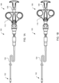
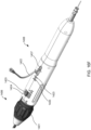
- Apparatus 100 may include distal end 102, catheter 104, and proximal end 106 having handle 108.
- Distal end 102 comprises components suitable for coupling apparatus 100 to devices of the present invention, as described in detail below.
- Catheter 104 comprises a biocompatible tube shaft of suitable size, e.g., approximately 14 Fr., and suitable length, e.g., approximately 75-100 cm and preferably 85 cm.
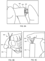
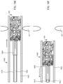
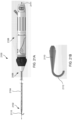
- Proximal end 106 comprises handle 108 that is configured to be manipulated, e.g., by a human hand, to transition components in distal end 102 from an engaged position shown in FIG. 1A to a disengaged position shown in FIG. 1B .
- Handle 108 may be manipulated, for example, by moving finger grips 110 proximally from a locked position shown in FIG. 1A to an unlocked position shown in FIG. 1B .
- handle 108 may be manipulated by moving finger grips 110 distally from the locked position to the unlocked position so as to transition components in distal end 102 from the disengaged position to the engaged position to load devices of the present invention.
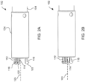
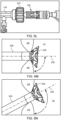
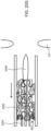
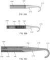
- FIGS. 2A and 2B illustrate distal end 102 in the engaged position of FIG. 1A and the disengaged position of FIG. 1B , respectively.
- apparatus 100 may include latching legs 112, 114, and 116 having hook portions 118, 120, and 122, respectively.
- Latching legs 112, 114, and 116 comprise a biocompatible material such as a biocompatible metal or polymer, and are positioned longitudinally and radially so as to firmly secure devices of the present invention for delivery.
- Hook portions 118, 120, and 122 extend outwardly from the distal end of latching legs 112, 114, and 116, respectively, and are configured to fit securely between struts and rings of the devices of the present invention.
- Catheter 104 may include cover tube 124 which may have a larger diameter than the remaining shaft of catheter 104.
- Cover tube 124 comprises a biocompatible material such as a biocompatible metal or polymer, and may be the same or different material than the remaining shaft of catheter 104.
- Components at distal end 102, such as latching legs 112, 114, and 116, may be at least partially disposed within cover tube 124.
- the proximal ends of latching legs 112, 114, and 116 may be coupled to annular member 148 and cover tube 124 by laser welding.
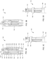
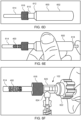
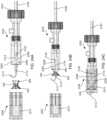
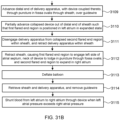
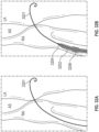
- FIGS. 3A to 3D the inner components at distal end 102 of apparatus 100 are illustrated.
- FIGS. 3A and 3B respectively illustrate distal end 102 in the engaged position of FIGS. 1A and 2A and the disengaged position of FIGS. 1B and 2B .
- catheter 104 and cover tube 124 comprise lumens 126 and 128, respectively, for housing the inner components.
- Latching legs 112 and 114 share common ramp portion 130 having inner section 132 and outer section 134 while latching leg 116 has separate ramp portion 136 having inner section 138 and outer section 140.
- Inner sections 132 and 138 are angled so as to be positioned closer to the central axis of catheter 104 and cover tube 124 relative to the positions of outer sections 134 and 140.
- Latching legs may also include jogs and protrusions.
- latching leg 116 illustratively includes protrusion 142 proximal to ramp portion 136, and jog 144 between hook portion 122 and ramp portion 136.
- Protrusion 142 is configured to contact the distal surface of annular member 148 to maintain suitable positioning of latching leg 116.
- Jog 144 is shaped to prevent release ring 146 from moving too distally.
- Release ring 146 may be moved to a second position, e.g., a disengaged position, where release ring 146 contacts outer sections 134 and 140 of ramp portions 130 and 136 such that latching legs 112, 114, and 116 move radially inward as shown in FIGS. 3B and 3D .
- release ring 146 is configured to move from the second position to the first position to load a device of the present invention and to move from the first position to the second position to release the device.
- Annular member 148 may be partially disposed in the proximal end of cover tube 124 and configured to couple cover tube 124 to catheter 104 via a suitable coupling mechanism, e.g., teeth 150, ribs. Annular member 148 includes lumen 152 sized to accept pull-cord 154 therethrough.
- Pull-cord 154 may be coupled to release ring 146 via release ring base 156.
- release ring base 156 is directly coupled to release ring 146 and pull-cord 154 such that actuation of pull-cord 154 moves release ring base 156 to move release ring 146 from the first position the second position, and vice versa.
- Spring 158 may be coupled to the proximal surface of release ring base 156 and the distal surface of annular member 148 such that release ring base 156 and annular member 148 maintain spring 158 therebetween.
- Spring 158 is configured to bias release ring 146 towards a particular position such as towards the first position as shown in FIG. 3A .
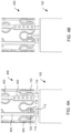
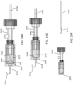
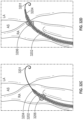
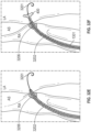
- FIGS. 3A and 3C illustrate the components at distal end 102 in an engaged position, where FIG. 3C omits cover tube 124 for clarity.
- pull-cord 154 is actuated, e.g., via handle 108
- release ring 146 is moved, e.g., via release ring base 156, from the engaged position to the disengaged position shown in FIGS. 3B and 3D , where FIG. 3D omits cover tube 124 for clarity.
- Release ring 146 slides along ramp portions 130 and 136 from inner sections 132 and 138 to outer sections 134 and 140 such that latching legs 112, 114, and 116 move from being extended radially outward to being positioned radially inward.
- spring 158 is compressed and as release ring 146 moves from the disengaged position to the engaged position, spring 158 is decompressed.
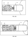
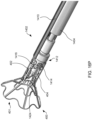
- FIG. 4A illustrates the components at distal end 102 of apparatus 100 engaged to an exemplary device of the present invention
- FIG. 4B illustrates the components disengaged from the exemplary device.
- Device 400 includes rings 402 and struts 404 and may be constructed similar to devices described in U.S. Patent No. 9,629,715 to Nitzan , U.S. Patent No. 9,713,696 to Yacoby , and U.S. Patent No. 10,076,403 to Eigler , assigned to the assignee of the present invention, the entire contents of each of which are incorporated herein by reference. As shown in FIG.
- hook portions 118, 120, 122 may extend radially to the outer surface of device 400 or beyond the outer surface of device 400.
- latching legs 112, 114, and 116 are configured to move radially inward a sufficient distance to decouple hook portions 118, 120, and 122 from device 400 in the disengaged position, thereby releasing device 400 for implantation.
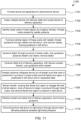
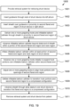
- FIG. 5 is a flowchart of exemplary method 500 of delivering device 400 illustrated in FIGS. 4A and 4B to reduce left atrial pressure in a subject, for example, a human having CHF, using apparatus 100 illustrated in FIGS. 1A-1B . Some of the steps of method 500 may be further elaborated by referring to FIGS. 6A-6Q .
- the device may be an hourglass-shaped device having a plurality of sinusoidal rings connected by longitudinally extending struts that define first and second flared end regions and a neck disposed therebetween, as well as an optional tissue valve coupled to the second flared end region.
- device 400 may be loaded into tapered loading tube 600 by first placing device 400 within wide diameter end 602 of loading tube 600 as shown in FIG. 6A . Then, using loading tool 604, device 400 is crimped down within loading tube 600.
- Loading tool 604 includes thin leg end 606 having two thin legs and wide leg end 608 having two wide legs. Device 400 may be pushed into loading tube 600 first by thin leg end 606 as illustrated in FIG. 6B and then pushed further into loading tube 600 by wide leg end 608 as illustrated in FIG. 6C .
- thin leg end 606 may have more than two thin legs, e.g., three, four, or more thin legs, and accordingly, wide leg end 608 may have more than two wide legs, e.g., three, four, or more wide legs.
- device 400 is disposed within thin diameter end 610 of loading tube 600.
- Thin diameter end 610 has a suitable internal diameter for contracting the device, e.g., approximately 14 Fr.
- Loading tube 600 includes tapered section 612 between wide diameter end 602 and thin diameter end 610. Tapered section 612 facilitates radial compression of device 400 into thin diameter end 610.
- Loading tube 600 is coupled to loading cartridge 614 via coupling section 616 having a suitable coupling mechanism, e.g., threads, ribs.
- Loading cartridge 614 may be transparent and has a suitable internal diameter, e.g., approximately 14 Fr.
- Pusher 618 has a suitable diameter, e.g., approximately 14 Fr., and may have a "star"-shaped end (not shown).
- the thin leg end of loading tool 604 is long enough to serve as pusher 618.
- Loading cartridge 614 is disconnected from loading tube 600 and connected to hemostasis valve section 620, which may be a Tuohy-Borst valve, as shown in FIG. 6F .
- Valve section 620 includes knob 622 and Y-connector 624. Distal end 102 of apparatus 100 is inserted through knob 622 of valve section 620.
- Knob 622 and Y-connector 624 are adjusted to permit movement of apparatus 100 while maintaining a seal to prevent fluid leakage, e.g., air leakage, blood leakage.
- the steps shown in FIGS. 6A-6F may be performed while device 400 is immersed in an anticoagulant such as heparinized saline.
- FIGS. 6G and 6H illustrate coupling device 400 to apparatus 100 at distal end 102.
- Distal end 102 is advanced within loading cartridge 614 toward device 400.
- the components of distal end 102 may be in the disengaged position as illustrated in FIG. 6G .
- the release ring at distal end 102 may contact an outer section of the ramp portions of the latching legs such that the latching legs are disposed radially inward.
- distal end 102 is moved longitudinally toward device 400 and rotated to align the latching legs with suitable portions of device 400, e.g., at openings between struts and rings of device 400.
- suitable position is achieved, the components of distal end 102 may move to the engaged position as illustrated in FIG. 6H .
- a trans-septal puncture device e.g., a mechanical needle such as a BROCKENBROUGH needle or a radiofrequency trans-septal puncture device, may be percutaneously introduced into the right atrium via the subject's venous vasculature, for example, via the femoral artery. Then, under fluoroscopic and/or echocardiographic visualization, the needle is pressed against the fossa ovalis, at a pressure insufficient to puncture the fossa ovalis.
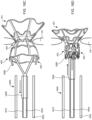
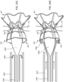
- device 400 may be positioned across the atrial septum AS, e.g., across a puncture through the fossa ovalis, at a non-perpendicular angle between center axis 628 and the outer wall of the atrial septum at the left atrial side below device 400.
- the angle ⁇ ' may be substantially greater than 90 degrees as shown in FIG. 6N .
- Such an angle may be appropriate when device 400, sheath 626, apparatus 100, and/or catheter 104 are advanced toward the atrial septum transapically or through the inferior vena cava.
- An hourglass shape may aid in non-perpendicular deployment because the flared ends of the device engage the atrial septum, even when positioned at an angle relative to the central axis of the puncture through the atrial septum.
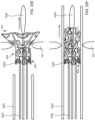
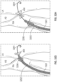
- first flared end of the device protrudes from sheath 626 and then knob 622 of Tuohy-Borst connector 620 is used to lock the delivery system in place within the sheath 626.
- Sheath 626, along with the delivery system 100 are pulled proximally causing the first flared end region of device 400 to engage the left side of the atrial septum AS as shown in FIG. 6M .
- device 400 is prevented from accidental deployment wholly within the left atrium LA, which may also assist in positioning the device when advanced at non-perpendicular angles as described in FIGS. 6N and 6O .
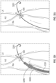
- the clinician next verifies that the device is positioned across the fossa ovalis. The clinician then reduces the pulling force of the sheath and allows the fossa ovalis to straighten. Then, while holding sheath 626 in place, knob 622 is released and the components at distal end 102 of apparatus 100 are moved from an engaged position to a disengaged position, e.g., by actuating handle 108 as shown in FIG. 6P . Then, apparatus 100 is pulled proximally with the sheath 626 a predetermined distance, e.g., approximately 5-6 cm.
- a predetermined distance e.g., approximately 5-6 cm.
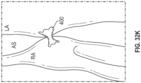
- the shunt device then may be fully deployed by pulling the sheath proximally causing the first flared end region to engage the left side of the atrial septum and the neck of the device to lodge in the puncture through the fossa ovalis, and allowing expansion of the second flared end of the device into the right atrium as shown in FIG. 6Q (step 508). Any remaining components of the delivery system then may be removed, e.g., sheath and distal end of delivery apparatus (step 509). Once positioned in the fossa ovalis, the device shunts blood from the left atrium to the right atrium when the left atrial pressure exceeds the right atrial pressure (step 510), thus facilitating treatment and/or the amelioration of symptoms associated with CHF.
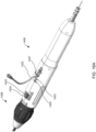
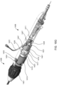
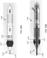
- Apparatus 700 includes distal end 702, catheter 704, proximal end 706, and knob system 703. Distal end 702 comprises components suitable for coupling apparatus 700 to devices of the present invention, as described in detail below.
- Catheter 704 comprises a biocompatible tube shaft of suitable size, e.g., approximately 14 Fr., and suitable length, e.g., approximately 75-100 cm and preferably 85 cm.
- Proximal end 706 includes handle 708 that is designed to be manipulated, e.g., by a human hand, to transition components in distal end 702 from an engaged position to a disengaged position.
- apparatus 700 includes Luer connector 705 in communication with control tube 707 extending from proximal end 706 to distal end 702 of apparatus 100.
- control tube 707 may extend through catheter 704 and through handle 708 for over-the-wire flushing, e.g., via a Tuohy Borst adapter connected to apparatus 700.
- Control tube 707 has a lumen extending therethrough sized to receive a guidewire.
- handle 708 may be manipulated, for example, by moving finger grips 710 proximally from a locked position shown to an unlocked position.
- handle 708 may be manipulated by moving finger grips 710 distally from the locked position to the unlocked position so as to transition components in distal end 702 from the disengaged position to the engaged position to load devices of the present invention.
- Handle 708 also may include securement mechanism 709 coupled to handle safety lock 711 such that finger grips 710 cannot be moved until handle safety lock 711 is released. Upon activation, handle 708 is retained in position, enabling a single user to perform the procedure.
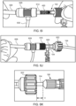
- FIGS. 8A and 8B illustrate distal end 702 in the engaged position and the disengaged position, respectively.
- apparatus 700 may include latching legs 712, 714, and 716 having hook portions 718, 720, and 722, respectively.
- Latching legs 712, 714, and 716 comprise a biocompatible material such as a biocompatible metal or polymer, and are positioned longitudinally and radially so as to firmly secure devices of the present invention for delivery.
- Hook portions 718, 720, and 722 extend outwardly from the distal end of latching legs 712, 714, and 716, respectively, and are configured to fit securely between struts and rings of the devices of the present invention.
- hook portions 718, 720, and 722 hook outwardly away from center axis 723 of catheter 704 in both the engaged and disengaged positions as shown in FIGS. 8A and 8B .
- Center axis 723 is centered relative to catheter 704 on both a longitudinal and cross-sectional basis.
- hook portions 718, 720, and 722 may engage the inner surface of the device, e.g., within a lumen of a shunt.
- hook portions 718, 720, and 722 move generally radially away from center axis 723.
- the angle between the lower surface of the hook portion and the longitudinal axis of the latching leg is preferably less than 90 degrees and greater than 75 degrees, e.g., 87 degrees, as shown in FIG. 8C to enable a more secure engagement with the shunt.
- 75 degrees could result in failure to disengage the shunt from the delivery device after deployment
- an angle greater than 90 degrees could result in failure to achieve half-way retrieval of the shunt by the delivery device.
- Such improved engagement allows the delivery device to pull the distal flange of a half-deployed shunt back into the sheath ("halfway-retrieval") in the event the shunt's distal flange is deployed in an undesired location.
- half-retrieval halfway-retrieval
- latching legs may be used without departing from the scope of the present invention. For example, one, two, four, five, six, or more latching legs may be used.
- Catheter 704 may include cover tube 724 which may have a larger diameter than the remaining shaft of catheter 704.
- Cover tube 724 comprises a biocompatible material such as a biocompatible metal or polymer, and may be the same or different material than the remaining shaft of catheter 704.
- Components at distal end 702, such as latching legs 712, 714, and 716, may be at least partially disposed within cover tube 724.
- distal end 702 includes control tube 707, e.g., a polyether ether ketone (PEEK) tube, having a lumen extending therethrough sized to receive a guidewire, as described in more detail below.
- PEEK polyether ether ketone
- Control tube 707 is moveable between an engaged position, where the distal end of control tube 707 extends past the distal end of cover tube 724 as shown in FIG. 8A , and a disengaged position, where the distal end of control tube 707 is moved proximally, but still extends past the distal end of cover tube 724 as shown in FIG. 8B .
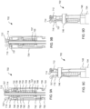
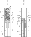
- FIGS. 9A to 9D respectively illustrate distal end 702 in the engaged position of FIG. 8A and the disengaged position of FIG. 8B , respectively.
- catheter 704 and cover tube 724 comprise lumens 726 and 728, respectively, for housing the inner components.
- Latching legs 712 and 714 share common ramp portion 730 having inner section 732 and outer section 734 while latching leg 716 has separate ramp portion 736 having inner section 738 and outer section 740.
- Inner sections 732 and 738 are angled so as to be positioned closer to central axis 723 of catheter 704 and cover tube 724 relative to the positions of outer sections 734 and 740.
- Latching legs may also include jogs and protrusions.
- latching leg 716 illustratively includes protrusion 742 proximal to ramp portion 736, and jog 744 between hook portion 722 and ramp portion 736.
- Protrusion 742 is configured to contact the distal surface of annular member 748 to maintain suitable positioning of latching leg 716.
- Jog 744 is shaped to prevent release ring 746 from moving too far distally.
- Release ring 746 is coupled to latching legs 712, 714, and 716.
- latching legs 712, 714, and 716 may be partially disposed within release ring 746 as illustrated in FIGS. 9A to 9D .
- Release ring 746 is moveable within cover tube 724.
- Release ring 746 may be located in a first position, e.g., an engaged position, where release ring 746 contacts inner sections 732 and 738 of ramp portions 730 and 736 such that latching legs 712, 714, and 716 extend radially outward as shown in FIGS. 9A and 9C .
- Release ring 746 may be moved to a second position, e.g., a disengaged position, where release ring 746 contacts outer sections 734 and 740 of ramp portions 730 and 736 such that latching legs 712, 714, and 716 move radially inward as shown in FIGS. 9B and 9D .
- release ring 746 is configured to move from the second position to the first position to load a device of the present invention and to move from the first position to the second position to release the device.
- Annular member 748 may be partially disposed in the proximal end of cover tube 724 and configured to couple cover tube 724 to catheter 704 via a suitable coupling mechanism, e.g., teeth 750, ribs. Annular member 748 includes lumen 752 sized to accept control tube 707 therethrough.
- Control tube 707 is coupled to release ring 746 and actuation of control tube 707 moves release ring 746 from the first position shown in FIG. 9A to the second position shown in FIG. 9B , and vice versa.
- control tube 707 is coupled to handle 708 such that control tube 707 is actuated by moving finger grips 710 from a locked position to an unlocked position, and vice versa.
- control tube 707 includes lumen 755 extending therethrough sized to receive a guidewire such that distal end 702 of apparatus 700 may be advanced over a guidewire to the desired device deployment location. The over-the-wire capability enables safe retrieval of a fully embolized device.
- Control tube 707 may be coupled to release ring 746 via release ring base 756.
- release ring base 756 is directly coupled to release ring 746 and control tube 707 such that actuation of control tube 707 moves release ring base 756 to move release ring 746 from the first position the second position, and vice versa.
- Spring 758 may be coupled to the proximal surface of release ring base 756 and the distal surface of annular member 748 such that release ring base 756 and annular member 748 maintain spring 758 therebetween.
- Spring 758 is configured to bias release ring 746 towards a particular position such as towards the first position as shown in FIG. 9A .
- FIGS. 9A and 9C illustrate the components at distal end 702 in an engaged position, where FIG. 9C omits cover tube 724 for clarity.
- release ring 746 is moved, e.g., via release ring base 756, from the engaged position to the disengaged position shown in FIGS. 9B and 9D , where FIG. 9D omits cover tube 724 for clarity.
- Release ring 746 slides along ramp portions 730 and 736 from inner sections 732 and 738 to outer sections 734 and 740 such that latching legs 712, 714, and 716 move from being extended radially outward to being positioned radially inward.
- spring 758 is compressed and as release ring 746 moves from the disengaged position to the engaged position, spring 758 is decompressed.
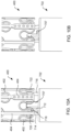
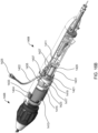
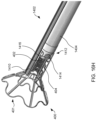
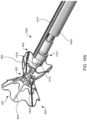
- FIG. 10A illustrates the components at distal end 702 of apparatus 700 engaged to an exemplary interatrial shunt device
- FIG. 10B illustrates the components disengaged from the exemplary device.
- Device 400 includes rings 402 and struts 404 and may be constructed similar to devices described in U.S. Patent No. 9,629,715 to Nitzan , U.S. Patent No. 9,713,696 to Yacoby , and U.S. Patent No. 10,076,403 to Eigler . As shown in FIG.
- latching legs 712, 714, and 716 are sized, shaped, angled, and spaced apart from one another so as to engage device 400 in openings between rings 402 and struts 404 when device 400 is in a contracted, delivery state.
- Hook portions 718, 720, and 722 also are sized, shaped, and angled to fit between rings 402 and struts 404 and hook portions 718, 720, 722 hook outwardly away from the center axis at the distal end of the delivery apparatus such that hook portions 718, 720, 722 are disposed in the lumen of device 400 in the engaged position of FIG. 10A and engage at the inner surface of device 400.
- hook portions 718, 720, and 722 move radially away from center axis 723 at an angle less than 90 degrees, e.g., 87 degrees, toward proximal end 706 of apparatus 700 as shown in FIG. 8C to enable halfway retrieval of a partially deployed device.
- latching legs 712, 714, and 716 are configured to move radially inward a sufficient distance to decouple hook portions 718, 720, and 722 from device 400 in the disengaged position, thereby releasing device 400 for implantation.
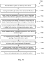
- FIG. 11 is a flowchart of exemplary method 1100 of delivering device 400 to reduce left atrial pressure in a subject, for example, a human having a heart condition, using apparatus 700 illustrated in FIGS. 7A and 7B .
- Steps 1101-1104 are similar to steps 501-504 described in FIG. 5 , except that apparatus 700 is used instead of apparatus 100, and for brevity are not discussed again here.
- a dilator having a guidewire lumen sized and shaped to receive the guidewire therethrough is advanced over the guidewire across the atrial septum through the fossa ovalis into the left atrium.
- a sheath is then advanced over the dilator across the atrial septum through the fossa ovalis into the left atrium.
- a sheath having a dilator disposed therein may be advanced together over the guidewire across the atrial septum through the fossa ovalis into the left atrium.
- distal end 702 of apparatus 700 is advanced through the sheath over the guidewire until proximal end 706 of apparatus 700 is a predetermined distance from the proximal end of the sheath such that distal end 702 of apparatus 700 is a predetermined distance from the distal end of the sheath.
- the guidewire is received from the Luer connector 705 via lumen 755 of control tube 707.
- Steps 1107-1110 are similar to steps 507-510 described in FIG. 5 , except that apparatus 700 is used instead of apparatus 100 and the guidewire may be removed through Luer connector 705 at step 1109, and for brevity are not described again herein.
- the components at distal end 702 of apparatus 700 e.g., latching legs 712, 714, and 716
- a disengaged position e.g., by actuating the handle at proximal end 706 to decouple hook portions 718, 720, and 722 from device 400 in the disengaged position, before the sheath is retracted to deploy device 400 within the atrial septum.
- knob system 703 may be used for length adjustment of apparatus 700 relative to the sheath during deployment of device 400 at the atrial septum, e.g., to assist in halfway retrieval of device 400.
- knob system 703 includes proximal knob 1202, distal knob 1204, and optional lock nut 1206.
- proximal knob 1202 may be pulled proximally to enable rotating distal knob 1204 clockwise to assist in "halfway retrieval" of device 400 as described here.
- Distal knob 1204 is rotatable to shorten the distance between the knob 1204 and the distal end 702 of apparatus 700, thus pulling distal end 702 proximally within the sheath.
- distal knob 1204 may be rotated clockwise to retract distal end 702, and thus device 400, within the sheath. As distal end 702 is retracted within the sheath, device 400 is also retracted, thus causing the first flared end region to collapse into the sheath.
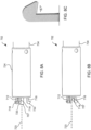
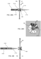
- FIG. 13A when hook portions 1308 and 1310 are in the disengaged position as described in FIGS. 2B , 3B , 3D , 8B , 9B, and 9D , hook portions 1308 and 1310 do not extend beyond the diameter of tube 1304 which prevents the risk of entanglement.
- tube 1304 may include a corresponding number of windows.
- Distal end 1301 is constructed similar to distal end 1302 described in FIG. 13A , and accordingly, distal end 102 described in FIGS. 2A to 3D and/or distal end 702 described in FIGS. 8A to 9D , except that instead of tube 1304, distal end 1301 includes cap 1303 extending distally from cover tube 1305.
- distal end 1301 includes one or more hook portions 1307 that move away from a center axis of the catheter as described above, and cap 1303 includes one or more windows 1309 sized for hook portions 1307 to protrude through in the engaged position as described above to engage device 400 in a collapsed state within the sheath.
- Cap 1303 has a rounded surface and is sized and shaped such that when hooks portions 1307 are retracted, cap 1303 prevents the shunt from being dragged inward along with hooks portions 1307, insuring that the shunt is released.
- tube 1304 and cap 1303 may be two separate components coupled together or may be formed as a single unitary component.
- hook portions 1307 is coupled to ramp portion 1311 that interacts with release ring 1313 to cause hook portions 1307 to move radially inward/outward responsive to the longitudinal position of release ring 1313 relative to ramp portion 1311.
- release ring 1313 is positioned along ramp portion 1311 such that hook portions 1307 protrudes out through windows 1309 of cap 1303.
- the inner surface of cover tube 1305 may include ridge 1317 sized and shaped to prevent release ring 1313 from moving too far distally within cover tube 1305.
- spring 1317 may cause release ring 1313 to be pushed against ridge 1317, thereby biasing hook portions 1307 in the engaged positioned, unless actuated by the user.
- release ring 1313 may be moved proximally via pull-chord 1315.
- hook portions 1317 move radially inward toward the central axis of the catheter within window 1309, to thereby disengage with the shunt device without dragging the shunt device inward and insure that the shunt device is released.
- Apparatus 1400 may include inner catheter 1411 extending from distal end 1402 through catheter 1404 and through proximal end 1406, e.g., past the proximal most part as shown.
- Inner catheter 1411 has a lumen sized to receive a guidewire therethrough.
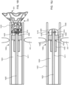
- FIG. 16A is a perspective view of proximal end 1406 of apparatus 1400 and FIG. 16B is a partial cross-sectional view illustrating internal components.
- FIGS. 16A-16T is a perspective view of proximal end 1406 of apparatus 1400 and FIG. 16B is a partial cross-sectional view illustrating internal components.
- Handle 1408 includes first actuator 1422, second actuator 1423, and third actuator 1424 for actuating the components within the distal region of sheath 1410 such that the shunt transitions between a contracted delivery state, to a partially expanded state, and then to a fully expanded deployed state.
- First, second, and third actuators 1422, 1423, and 1424 may be buttons, switches, levers, touchscreens, or the like.
- First, second, and third actuators 1422, 1423, and 1424 may be combined into a single component, two components, or may be more than three components.
- handle 1408 includes knob 1401.
- the inner components of knob 1401 includes a threaded portion that corresponds with a threaded portion coupled to sheath 1410. Accordingly, as knob 1401 is rotated about the longitudinal axis of handle 1408, rotational movement of knob 1401 is converted to translational movement of the threaded portion coupled to sheath 1410 along the longitudinal axis of handle 1408, thereby causing movement of sheath 1410 relative to catheter 1404. This permits gradual adjustment of the length of sheath 1410 relative to catheter 1404, and accordingly halfway-retrieval of device 400 when device is halfway deployed as will be described in further detail below. Knob 1401 may not be rotated until third actuator 1424 is moved from a locked position to an unlocked position.
- third actuator 1424 may be coupled to third actuator component 1413 rotatable about the longitudinal axis of handle 1408, parallel to inner catheter 1411, between a first, second, and third position.
- FIGS. 16A and 16B illustrate third actuator 1424 in the first position, such that third actuator 1424 is centered within opening 1433 of the housing of handle 1408.
- Third actuator component 1413 may include a toothed pattern along its proximal end for engaging with a corresponding indent along the distal end of actuator ring 1415, wherein actuator ring 1415 is freely rotatable about the longitudinal axis of handle 1408. As shown in FIG.
- third actuator 1424 When third actuator 1424 is moved to the second position, such that third actuator component 1413 is rotated, e.g., counter-clockwise, about the longitudinal axis of handle 1408, the space between the edge of the tooth of third actuator component 1413 and the edge of the indent of actuator ring 1415 increases such that actuator ring 1415 is free to rotate in the same direction, e.g., counter-clockwise until the edge of the indent of actuator ring 1415 engages with the edge of the tooth of third actuator component 1413.
- third actuator component 1413 is operatively coupled to a locking mechanism between inner catheter 1411 and a hub disposed within the distal region of sheath 1410 as described in further detail below.
- Actuator ring 1415 also may include a grooved pattern along its proximal end for engaging with a corresponding indent along the distal end of second actuator component 1417 coupled to second actuator 1423. Accordingly, the edge of the tooth of third actuator component 1413 may further engage with the indent of actuator ring 1415, to thereby rotate actuator ring 1415 until the groove of actuator ring 1415 engages with the indent of second actuator component 1417.
- Second actuator 1423 may be moveable between a first and second position. For example, FIGS. 16A and 16B illustrate second actuator 1423 in the first position, such that first actuator 1423 is positioned proximally relative to opening 1435 of the housing of handle 1408.
- Third actuator component 1413, actuator ring 1415, and second actuator component 1423 include a lumen sized and shaped to receive first actuator component 1419 coupled to first actuator 1422.
- the lumens of third actuator component 1413 and actuator ring 1415 are sized and shaped to permit rotation about first actuator component 1419, whereas the lumen of second actuator component 1417 may be sized and shaped such that second actuator component 1417 is only permitted to move longitudinally along first actuator component 1419.
- One or more guiderails 1413 are coupled at one end to second actuator component 1417, and coupled at an opposite end to pusher plate 1440 disposed at the proximal end of handle 1408, wherein pusher plate 1440 is fixedly coupled to a proximal portion of inner catheter 1411. Accordingly, movement of second actuator component 1417 from the first position to the second position causes pusher plate to move distally within the housing of handle 1408 via guiderails 1413, thereby causing inner catheter 1411 to move distally within the distal region of sheath 1410.
- First actuator component 1419 includes a lumen sized and shaped to receive centering element 1429, wherein centering element 1429 is fixed relative to handle 1408.
- First actuator 1422 is further coupled to proximal portion 1427 sized and shaped to move within a lumen of centering element 1429.
- Proximal portion 1427 includes a lumen sized and shaped to receive inner catheter 1411, such that proximal portion 1427 is moveable between the first and second positions along inner catheter 1411.
- First actuator 1422 may be moveably coupled to inner catheter 1411 via proximal portion 1427, and may include port 1425 for coupling to a fluid source to introduce fluid into the guidewire lumen of inner catheter 1411 for flushing.
- first actuator component 1419 is coupled to sheath 1410 for extending and retracting the distal end of sheath 1410 as described in further detail below.
- Engagement portion 1428 of hub 1412 has a diameter less than that of ring portion 1426, such that device 400 may fit between the outer surface of engagement portion 1428 and sheath 1410 when device 400 is in a collapsed, delivery state.
- Engagement portion 1428 may have a cylindrical shape and a curved distal end as shown.
- Hub 1412 is moveable relative to catheter 1404 within sheath 1410 along an inner catheter disposed within a lumen extending through hub 1412 and catheter 1404 as described in further detail below.
- Hub 1412 is releaseably coupled to the distal end of catheter 1404 via a locking mechanism operatively coupled to third actuator 1424, such that actuation of third actuator 1424 from the first position to the second position causes the locking mechanism to unlock, thereby decoupling hub 1412 from catheter 1404.
- hub 1412 includes one or more engagers, e.g., protrusions 1414 and 1416, extending radially outward from a central axis of catheter 1404, such that the one or more engagers are disposed circumferentially about the outer surface of hub 1412, e.g., at engagement portion 1428, and are configured to fit securely between struts and rings of the interatrial devices for delivery.
- each of the one or more engagers may be sized to engage device 400 in openings between rings 402 and struts 404 when device 400 is in a contracted, delivery state.
- protrusions 1414 and 1416 engage device 400 in openings between rings 402 and struts 404 such that device 400 is constrained between hub 1412 and the inner wall of sheath 1410 in a contracted, delivery state.
- two engagers are illustrated, more or fewer engagers may be used without departing from the scope of the present invention. For example, one, three, four, five, six, seven, eight, or more engagers may be used.
- FIG. 16D is a partial cross-sectional schematic of the delivery apparatus within the sheath during step 1506, wherein the delivery apparatus is coupled to device 400
- FIG. 16E illustrates the delivery apparatus of FIG. 16D with device 400 omitted for clarity.
- the distal end of sheath 1410, with the delivery apparatus disposed therein is advanced across the atrial septum AS.
- Protrusions 1414 and 1416 fit securely between struts and rings of device 400 such that device 400 is constrained between protrusions 1414 and 1416 and ring portion 1426, and between engagement portion 1428 and sheath 1410.
- FIG. 16D is a partial cross-sectional schematic of the delivery apparatus within the sheath during step 1506, wherein the delivery apparatus is coupled to device 400
- FIG. 16E illustrates the delivery apparatus of FIG. 16D with device 400 omitted for clarity.
- the distal end of sheath 1410, with the delivery apparatus disposed therein is advanced across the atrial septum AS.
- hub 1412 is adjacent to catheter 1404 such that proximal portion 1432 of hub 1412 is disposed within cavity 1436 of catheter 1404.
- Cavity 1436 is sized and shaped to receive proximal portion 1432 of hub 1412 a predetermined distance. Cavity 1436 has a larger outer diameter than the outer diameter for the lumen in catheter 1404 that receives inner catheter 1411.
- Proximal portion 1432 is coupled to ring portion 1426 via connector 1434.
- Hub 1412 may be releaseably coupled to catheter 1404 via a locking mechanism for engaging catheter 1404 to at least one of ring portion 1426 or proximal portion 1432.
- inner catheter 1411 is disposed within a central lumen extending through hub 1412 and catheter 1404.
- Inner catheter 1411 may include a stop, e.g., lock ring 1438, fixed at a distal end of inner catheter 1411, wherein lock ring 1438 is sized and shaped to be disposed within cavity 1430 of hub 1412.
- Cavity 1430 may extend through at least a portion of engagement portion 1428 of hub 1412, or completely through engagement portion 1428 of hub 1412 and at least a portion of ring portion 1426 of hub 1412.
- Lock ring 1438 ensures that hub 1412 does not extend beyond a predetermined distance distally along inner catheter 1411, and that inner catheter 1411 does not retract beyond the predetermined distance proximally relative to hub 1412.
- Inner catheter 1411 also may include guidewire lumen 1425 sized and shaped to receive a guidewire therethrough.
- delivery apparatus 1400 may be advanced over a guidewire such that the distal end of sheath 1410 having distal end 1402 coupled to device 400 disposed therein, is positioned across the fossa ovalis.
- first actuator 1422 is then moved from a first initial position to a second position within opening 1437 of the housing of handle 1408, which causes distal end 1402 including inner catheter 1411 and hub 1412 having device 400 coupled thereto, and catheter 1404 to move relative to sheath 1410.
- movement of first actuator 1422 causes first actuator component 1419 to move from the first initial position to the second position through the lumens of second actuator component 1417, actuator ring 1415, and third actuator component 1413 along guiderail 1431, and proximal portion 1427 to move from the first initial position to the second position along inner catheter 1411 within centering element 1429.
- first actuator 1424 moves from the first initial position to the second position causes first actuator component 1419 operatively coupled to sheath 1410 to move sheath 1410 relative to catheter 1404, hub 1412, and inner catheter 1411, thereby exposing first flared end region 401 of device 400 beyond the distal end of sheath 1410 such that first flared end region 401 expands to its deployed state in the left atrium as shown in FIG. 16H (step 1507).
- actuation of first actuator 1422 may cause catheter 1404, hub 1412, and inner catheter 1411 to be advanced distally while sheath 1410 remains stationary with respect to atrial septum AS.
- the delivery apparatus e.g., hub 1412 and catheter 1404 moves distally within sheath 1410 relative to sheath 1410, such that first flared end region 401 extends beyond the distal end of sheath 1410 and transitions from a collapsed, delivery state to an expanded, deployed state within the left atrium, while the second flared end of device 400 remains in a collapsed, delivery state within the distal end of sheath 1410.
- second actuator 1423 may then be moved from the first initial position to the second position which causes second actuator component 1417 to move distally along first actuator component 1419 within the housing of handle 1408.
- second actuator component 1417 moves distally along first actuator component 1419, the distal edge of second actuator component 1417 interacts with the groove of actuator ring 1415, thereby causing actuator ring 1415 to rotate until the indent of actuator ring 1415 engages with the edge of the tooth of third actuator component 1413.
- second actuator component 1417 moves from the first initial position to the second position via guiderails 1431 and pusher plate 1440 as illustrated in FIG. 16M .
- the delivery apparatus e.g., sheath 1410, inner catheter 1411, catheter 1404, and hub 1412 coupled to device 400, may be pulled proximally until first flared end region 401 engages the atrial septum from within the left atrium (step 1508).
- FIG. 16N is a cross-sectional schematic of the delivery apparatus within the sheath during step 1508, wherein inner catheter 1411 has been moved distally relative to sheath 1410, hub 1412, and catheter 1404 such that lock ring 1438 is no longer disposed within cavity 1430 of engagement portion 1428 of hub 1412, and the delivery apparatus is pulled proximally until first flared end region 401 engages the left side of atrial septum AS.
- FIG. 16O illustrates the delivery apparatus of FIG. 16N with device 400 omitted for clarity. Specifically, FIG. 16O illustrates sheath 1410, hub 1412, inner catheter 1411, and catheter 1404 pulled proximally with respect to atrial septum AS.
- the clinician next verifies that the device is positioned across the fossa ovalis.
- the clinician then reduces the pulling force of sheath 1410, catheter 1404, and hub 1412, and allows the fossa ovalis to straighten.
- the physician may reduce and/or stop the pulling force of the delivery apparatus upon force feedback provided by the atrial septum against the delivery apparatus, which indicates that device 400 is properly positioned within the opening of the atrial septum. This may prevent accidentally deploying the entire device in the left atrium and may assist in positioning the device when advanced at non-perpendicular angles.
- third actuator 1424 may then be moved from the first initial position to the second position, which causes third actuator component 1413 to rotate about first actuator component 1419.
- the engagement between the tooth of third actuator component 1413 and the indent of actuator ring 1415 allows rotation of third actuator component 1413 to rotate actuator ring 1415 in the same direction, e.g., counter-clockwise, until the groove of actuator ring 1415 engages with the indent of second actuator component 1417. This causes the locking mechanism to decouple hub 1412 and catheter 1404 to permit full deployment of device 400.
- sheath 1410 may be advanced over device 400 while catheter 1404 is stationary, thereby collapsing first flared end region 401 within sheath 1410.
- knob 1401 of handle 1408 may be rotated to cause sheath 1410 to move translationally relative to catheter 1404 and device 400, to thereby collapse device 400 within sheath 1410.
- sheath 1410 may be moved over collapsed device 400 until device 400 is completely collapsed within sheath 1410.
- Distal end 1402, with device 400 disposed therein, may then be retrieved.
- distal end 1402 may be repositioned relative to the fossa ovalis of the atrial septum prior to partially advancing first flared end region 401 out of sheath 1410 within the left atrium.
- the delivery apparatus may be pulled proximally by the physician such that the atrial septum maintains device 400 in position against the left side of the atrial septum until second flared end region 403 of device 400 is no longer constrained between hub 1412 and sheath 1410 as shown in FIG. 16P .
- hub 1412 remains stationary with respect to the atrial septum as the one or more engagers of hub 1412 are engaged with the struts of second flared end region 403 of device 400 within sheath 1410.
- FIG. 16Q is a cross-sectional schematic of the delivery apparatus within the sheath during step 1509, wherein the delivery apparatus is pulled proximally such that second flared end region 403 of device 400 is no longer constrained between hub 1412 and sheath 1410.
- FIG. 16R illustrates the delivery apparatus of FIG. 16Q with device 400 omitted for clarity. As shown in FIG.
- sheath 1410 is no longer disposed over protrusions 1414 and 1416 such that second flared end region 403 is no longer constrained in the collapsed, delivery state, thereby causing first flared end region 401 to engage the left side of the atrial septum and neck region 405 of the device to lodge in the puncture through the fossa ovalis, and allowing expansion of second flared end region 403 of the device into the right atrium as shown in FIG. 16S .
- the inventive devices also may be used with patients having disorders other than heart failure.
- the device may be implanted in a subject suffering from myocardial infarction, for example in the period immediately following myocardial infarction (e.g., within a few days of the event, or within two weeks of the event, or even within six months of the event).
- the heart remodels to compensate for reduced myocardial function.
- such remodeling may cause the function of the left ventricle to significantly deteriorate, which may lead to development of heart failure.
- Implanting an inventive device during the period immediately following myocardial infarction may inhibit such deterioration in the left ventricle by reducing LAP and LVEDP during the remodeling period. The device optionally then may be removed as described in further detail below.
- Exemplary method 1700 of retrieving device 400 from a subject for example, from a puncture through the fossa ovalis, will now be described with reference to FIG. 17 .
- the steps of method 1700 may be further elaborated by referring to FIGS. 18A-18F .
- a guidewire is inserted through the neck of the implanted shunt device through the fossa ovalis of the atrial septum into the left atrium.
- the guidewire may be inserted using techniques readily known in the art.
- the sheath is inserted over the guidewire and positioned in proximity to the flared end region of the shunt device disposed in right atrium. The guidewire may then be removed.
- the retrieval catheter and the restraint member are delivered through the sheath in proximity to the flared end region of the shunt device disposed in right atrium.
- FIG. 18A is a partial cross-sectional schematic of retrieval system 1800 during step 1704. As illustrated in FIG.
- sheath 1802 having retrieval catheter 1804 and restraint member 1808 disposed therein is positioned in proximity to second flared end region 403 of device 400 within the right atrium. Restraint member 1808 is positioned over a portion of retrieval catheter 1804 such that hook portions 1806 are maintained in a compressed configuration within sheath 1802. Although only two hook portions 1806 are illustrated in FIG. 18A , as will be understood by a person ordinarily skilled in the art, retrieval catheter 1804 may include less or more than two hook portions, e.g., one, three, four, five, or six hook portions. Restraint member 1808 may be moved proximally and distally over retrieval catheter 1804 within sheath 1802 via control tube 1810. Alternatively, a control wire having sufficient stiffness may be used to move restraint member 1808 within sheath 1802.
- retrieval catheter 1804 along with restraint member 1808 are advanced distally and exposed beyond the distal end of sheath 1802 within the right atrium such that hook portions 1806 are within at least a portion of second flared end region 403 of device 400, as illustrated in FIG. 18B .
- restraint member 1808 is retracted proximally along retrieval catheter 1804 within sheath 1802 via control tube 1810. Accordingly, hook portions 1806 expand radially outward from the central axis of retrieval catheter 1804 as they are no longer restrained by restraint member 1808, as illustrated in FIG. 18C .
- retrieval catheter 1804 may be adjusted to align hook portions 1806 with the openings between the struts and rings of second flared end region 403 of device 400.
- step 1708 while hook portions 1806 are maintained in placed and engaged with second flared end region 403 of device 400, restraint member 1808 is advanced distally toward hook portions 1806 via control tube 1810, thereby causing hook portions 1806, and accordingly second flared end region 403, to transition to a compressed configuration, as illustrated in FIG. 18D .
- step 1709 sheath 1802 is advanced distally over retrieval catheter 1804 and device 400, through the atrial septum AS and into the left atrium, thereby causing first flared end region 401 of device 400 to transition to a compressed configuration within sheath 1802, as illustrated in FIG. 18E .
- system 1800 is pulled proximally to remove retrieval system 1800 and device 400 from the patient, as illustrated in FIG. 18F .
- exemplary method 1900 of retrieving device 400 from a subject for example, from a puncture through the fossa ovalis, will now be described with reference to FIG. 19 .
- the steps of method 1900 may be further elaborated by referring to FIGS. 20A-20G .
- FIG. 19 is a flow chart of steps in an exemplary method of retrieving an hourglass-shaped device implanted in a puncture through the fossa ovalis in accordance with the present invention.
- a retrieval system for retrieving an implanted shunt device e.g., hourglass-shaped device 400 of FIG. 4 .
- the retrieval system includes grappling hook having one or more hook portions at the distal region thereof which preferably are formed of a shape memory metal and are biased radially inward toward a central axis of the retrieval system, an inflatable balloon catheter, and a sheath having a lumen sized and shaped to receive the grappling hook and the inflatable balloon catheter.
- the one or more curved hooked portions of the grappling hook are sized and shaped to align with the openings between the struts and rings of the shunt device in an expanded state. Accordingly, the number of hook portions may correspond with the number of openings between the struts and rings of the shunt device.
- the inflatable balloon catheter may be delivered within a separate balloon channel moveable within the sheath.
- a guidewire is inserted through the neck of the implanted shunt device through the fossa ovalis of the atrial septum into the left atrium.
- the guidewire may be inserted using techniques readily known in the art.
- the sheath is inserted over the guidewire and positioned in proximity to the flared end region of the shunt device disposed in right atrium.
- the grappling hook and the inflatable balloon catheter are delivered through the sheath over the guidewire in proximity to the flared end region of the shunt device disposed in right atrium.
- FIG. 20A is a partial cross-sectional schematic of retrieval system 2000 during step 1904. As illustrated in FIG.
- sheath 2002 having grappling hook 2004 and inflatable balloon catheter 2008 in a deflated state disposed therein is positioned in proximity to second flared end region 403 of device 400 within the right atrium.
- grappling hook 2004 may include less or more than two hook portions 2006, e.g., one, three, four, five, or six hook portions.
- Hook portions 2006 of grappling hook 2004 may be joined together at a proximal region of grappling hook 2004, e.g., via a ring having a lumen sized and shaped to receive inflatable balloon catheter 2008 such that grappling hook 2004 may move proximally or distally over inflatable balloon catheter 2008 within sheath 2002.
- inflatable balloon catheter 2008 is advanced distally, e.g., over the guidewire (not shown), and exposed beyond the distal end of sheath 2002 within the right atrium in a deflated condition such that inflatable balloon catheter 2008 is positioned within at least a portion of second flared end region 403 of device 400, as illustrated in FIG. 20B .
- inflatable balloon catheter 2008 is inflated to an inflated state within at least a portion of second flared end region 403 and neck region 405 of device 400, as illustrated in FIG. 20C .
- inflatable balloon catheter 2008 may be coupled to a source of fluid at its proximal end outside the patient's body for inflation of inflatable balloon catheter 2008, and may expand to have a diameter equal to the diameter of neck region 405 of device 400. Inflation of inflatable balloon catheter 2008 aligns retrieval system 2000 with device 400.
- grappling hook 2004 is advanced distally and exposed beyond the distal end of sheath 2002 within the right atrium. As illustrated in FIG. 20D , hook portions 2006 of grappling hook 2004 bend radially outwardly in an expanded state as they move across the surface of inflatable balloon catheter 2008 in the inflated state. At step 1908, grappling hook 2004 may be adjusted to align hook portions 2006 with the openings between the struts and rings of second flared end region 403 of device 400.
- inflatable balloon catheter 2008 is deflated and advanced distally into the left atrium.
- inflatable balloon catheter 2008 may be deflated and removed from the patient's body or deflated and retracted into a balloon channel within sheath 2002. Deflation of inflatable balloon catheter 2008 causes hook portions 2006 of grappling hook 2004, and accordingly second flared end region 403, to transition to a compressed configuration, as illustrated in FIG. 20E .
- sheath 2002 is advanced distally over grappling hook 2004, device 400, and inflatable balloon catheter 2008, through the atrial septum AS and into the left atrium, thereby causing first flared end region 401 of device 400 to transition to a compressed configuration within sheath 2002, as illustrated in FIG. 20F .
- system 2000 is pulled proximally to remove retrieval system 2000 and device 400 from the patient, as illustrated in FIG. 18G.
- Apparatus 2100 includes distal end 2102, catheter 2104, and proximal end 2106 having handle 2108 for actuating distal end 2102.
- Distal end 2102 is removeably coupled to distal tip 2110 having flexible pigtail-shaped portion 2112 extending therefrom as illustrated in FIG. 21B .
- Apparatus 2100 may include an engagement apparatus disposed within catheter 2104 extending from proximal end 2106 to distal end 2102 for delivery and/or retrieval of the interatrial shunt device.
- the components of apparatus 2100 may include a guidewire lumen sized to receive a guidewire therethrough as described in further detail below.
- Loading tool 2200 includes proximal loader 2202 and distal loader 2204.
- Proximal loader 2202 and distal loader 2204 may be constructed from, e.g., injection molding, and made of a transparent plastic material such that loading of device 400 therein may be visible by the user.
- Proximal loader 2202 has lumen 2208 extending from proximal end 2201 to distal end 2203 of proximal loader 2202, wherein lumen 2208 is sized and shaped to receive device 400 in a collapsed delivery state as well as distal tip 2110 and catheter 2104 of apparatus 2100.
- lumen 2208 has conical shaped cavity 2206 at its distal open end which corresponds to the shape of one of the flared end regions of device 400, e.g., the flared end region configured to be disposed within the left atrium when device 400 is implanted.
- cavity 2206 is sized such that device 400 must be inserted into proximal loader 2202 in a specific orientation as will be described in further detail below, thereby ensuring proper loading of device 400 into apparatus 2100.
- distal loader 2204 has cavity 2210 sized and shaped to receive distal end 2203 of proximal loader 2202.
- FIG. 24A illustrates proximal loader 2202, distal loader 2204, the distal components of apparatus 2100, and device 400.
- apparatus 2100 is positioned within proximal loader 2202 such that the distal portion of catheter 2104 and engagement apparatus 2120 are disposed within lumen 2208, and distal tip 2110 extends beyond distal end 2203 of proximal loader 2202 (step 2301). As shown in FIG.
- distal tip 2110 is moveably coupled to catheter 2104 via pull-cord 2114.
- Engagement apparatus 2120 may be constructed similar to delivery apparatus 100 of FIG. 1A and delivery apparatus 700 of FIG. 7A .
- engagement apparatus 2120 includes latching legs having hook portions which may be controllably transitioned between a disengaged and engaged position for engaging with device 400 in a collapsed delivery state.
- Engagement apparatus 2120 is moveably disposed within the lumen of catheter 2104 and may be coupled to the distal end of an inner catheter disposed within catheter 2104.
- FIG. 24B illustrates device 400 coupled to distal tip 2110 of apparatus 2100 while apparatus 2100 is disposed within lumen 2208 of proximal loader 2202 (step 2302).
- device 400 is inserted over pigtail-shaped portion 2112 to be disposed over distal tip 2110, such that the outlet end of second flared end region 403 of device 400 is adjacent to cavity 2206 of proximal loader 2202.
- Cavity 2206 has a size and shape that corresponds to first flared end region 401 in an expanded state, and which may receive the outlet end of second flared end region 403 of device 400 in the expanded state. This ensures that device 400 is properly loaded into apparatus 2100 as the inlet end of first flared end region 401 could not be inserted into cavity 2206 of proximal loader 2202.
- FIG. 24C illustrates proximal loader 2202 having apparatus 2100 coupled to device 400 therein, advanced within cavity 2210 of distal loader 2204 (step 2303). Specifically, proximal loader 2202 is advanced within cavity 2210 of distal loader 2204 until first flared end region 401 of device 400 contacts the inner wall of cavity 2210. As proximal loader 2202, and accordingly apparatus 2201, are further advanced into cavity 2210 of distal loader 2204 (step 2304), second flared end region 403 transitions from an expanded stated to a collapsed delivery state within lumen 2208 of proximal loader 2202 as illustrated in FIG. 24D .
- proximal loader 2202 causes second flared end region 403 to crimp into the collapsed state as force is applied to second flared end region 403 by proximal loader 2202.
- pigtail-shaped portion 2212 and at least a portion of distal tip 2110 extend beyond an opening of distal loader 2204. Steps 2303 and 2304 may be completed in a single motion.
- the latching legs and hook portions of engagement apparatus 2120 may be actuated to be in a disengaged position, e.g., contracted inward, before proximal loader 2202 is completely advanced within distal loader 2204 so that the engagement hooks of engagement apparatus 2120 may be appropriately aligned with the struts of second flared end region 403 of device 400, and so that second flared end region 403 can smoothly enter lumen 2208 of proximal loader 2202.
- the latching legs and hook portions of engagement apparatus 2120 may be actuated to be in a engaged position to engage with second flared end region 403 of device 400 within lumen 2208 of proximal loader 2202 (step 2305).
- FIG. 24E illustrates catheter 2104 advanced further through lumen 2208 of proximal loader 2202 over engagement apparatus 2120, device 400, and pull-cord 2114 until the distal end of catheter 2104 engages with distal tip 2110 (step 2306).
- first flared end region 401 further advancement of catheter 2104 against the outer surface of first flared end region 401 cause first flared end region 401 to crimp into a collapsed state within the lumen of catheter 2104.
- the distal end of catheter 2104 may then be coupled to distal tip 2110 (step 2307).
- apparatus 2100 having device 400 in a collapsed delivery state therein and engaged with engagement apparatus 2120 within catheter 2104 of apparatus 2100 is removed from proximal loader 2202 and distal loader 2204 (step 2308).
- FIG. 25A illustrates catheter 2104 coupled to distal tip 2110 of apparatus 2100.
- apparatus 2100 may include radiopaque marker 2122 disposed at the distal end of catheter 2104 for assisting in accurate deployment of device 400 within the interatrial septum.
- radiopaque marker 2122 may be visualized by the physician during the delivery procedure to ensure that it is aligned with the atrial septum for proper delivery.
- FIG. 25B illustrates the components within catheter 2104 with device 400 loaded therein. As illustrated in FIG.
- collapsed device 400 is positioned within catheter 2104 such that one end is engaged with engagement apparatus 2120, and the other end is aligned with radiopaque marker 2122 so that the neck region of device 400 is a predetermined distance from radiopaque marker 2122.
- knowing where the neck region of device 400 is within catheter 2104 by knowing its distance from radiopaque marker 2122 will assist in proper and accurate deployment of device 400 within the fossa ovalis.
- FIG. 25C is a cross-sectional view of the distal end of apparatus 2100.
- apparatus 2100 may include guidewire lumen 2116 extending therethrough, e.g., from an opening at the end of pigtail-shaped portion 2116 through distal tip 2110 and pull-cord 2114 to the proximal end of apparatus 2100.
- Guidewire lumen 2116 is sized and shaped to receive a guidewire so that apparatus 2100 may be advanced over the guidewire across the atrial septum for implantation of device 400.
- engagement apparatus 2120 includes hook portions 2118 which may be constructed similar to the hook portions of delivery apparatus 100 of FIG. 1A and delivery apparatus 700 of FIG. 7A , for engaging and disengaging device 400 with engagement apparatus 2120.
- FIGS. 26A and 26B illustrates handle 2108 coupled to distal end 2106 of apparatus 2100.
- handle 2108 includes safety trigger 2126 and knob 2124.
- knob 2124 includes a threaded portion that corresponds with threaded portion of catheter component 2127 coupled to catheter 2104. Accordingly, as knob 2124 is rotated about the longitudinal axis of handle 2108, rotational movement of knob 2124 is converted to translational movement of catheter component 2127 along the longitudinal axis of handle 2108, thereby causing movement of catheter 2104 relative to engagement apparatus 2120.
- Knob 2124 may not be rotated until safety trigger 2126 is moved from a locked position to an unlocked position.
- Exemplary method 2700 of delivering device 400 to reduce left atrial pressure in a subject, for example, a human having a heart pathology, using apparatus 2100 illustrated in FIG. 21A will now be described with reference to FIG. 27 . Some of the steps of method 2700 may be further elaborated by referring to FIGS. 28A-28I .
- an interatrial shunt e.g., device 400, and apparatus 2100 of FIG. 21A for delivering device 400 are provided.
- device 400 is collapsed radially to a contracted delivery state and coupled to apparatus 2100, e.g., using method 2300 of FIG. 23 .
- Steps 2703 and 2704 are similar to steps 503 and 504 described in FIG. 5 , and thus for brevity these steps are not discussed again here.
- FIG. 28A illustrates guidewire 2801 disposed across the atrial septum in left atrium LA (step 2704).
- Pigtail-shaped portion 2112 of distal tip 2110 of delivery apparatus 2100 with device 400 collapsed therein and coupled to engagement apparatus 2120 of apparatus 2100 is then advanced over guidewire 2801 through the puncture in the fossa ovalis and into left atrium LA (step 2705) as illustrated in FIG. 28B .
- catheter 2104 is retracted proximally relative to distal tip 2110 and engagement apparatus 2120 coupled to collapsed device 400 such that device 400 is partially advanced out of catheter 2104 (step 2706).
- Such advancement causes device 400 to partially protrude out of catheter 2401 and into left atrium LA, which causes the first flared end region to expand to its deployed expanded state in the left atrium LA, as shown in FIG. 28C .
- apparatus 2100 may be repositioned such that radiopaque marker 2801 is aligned with the fossa ovalis (step 2707) as illustrated in FIGS. 28D and 28E .
- FIG. 28E when apparatus 2100 is in the proper position, the neck region of device 400 will be aligned with the fossa ovalis for accurate deployment of device 400 within the atrial septum.
- device 400 will be loaded to a specific position within catheter 2104 of apparatus 2100 relative to radiopaque marker 2122 during method 2300 described above.
- catheter 2104 may be advanced over device 400 while distal tip 2110 is stationary, thereby collapsing the first flared end region within catheter 2104 (step 2708) as illustrated in FIG. 28F .
- knob 2124 of handle 2108 may be rotated to cause catheter 2104 to move translationally relative to engagement apparatus 2120 and distal tip 2110 of apparatus 2100, to thereby collapse device 400 within catheter 2104.
- catheter 2104 may be moved over collapsed device 400 until catheter 2104 engages with distal tip 2110 as shown in FIG. 28F .
- Apparatus 2100, with device 400 disposed therein, may then be retrieved, e.g., over guidewire 2801 (step 2709).
- apparatus 2100 may be repositioned relative to the fossa ovalis of the atrial septum prior to returning to step 2706 and partially advancing the first flared end region out of catheter 2104 within left atrium LA.
- engagement apparatus 2120 may be disengaged from device 400, e.g., hook portions 2118 may be moved from an engaged positioned radially inward to a disengaged position. Then, catheter 2104 may be retracted proximally relative to distal tip 2110, causing the second flared end region of device 400 to be exposed within right atrium RA beyond the distal end of catheter 2104 such that the second flared end region transitions from the collapsed delivery state to an expanded state within right atrium RA (step 2710) as illustrated in FIG. 28G .
- knob 2124 of handle 2108 may be rotated in the opposite direction to cause catheter 2104 to move translationally relative to engagement apparatus 2120 and distal tip 2110 of apparatus 2100, to thereby expose the second flared end region of device 400 within right atrium RA. Accordingly, the flared end region of device 400 will be disposed within left atrium LA, the neck region of device 400 will be lodged within the puncture through the fossa ovalis, and the second flared end region of device 400 will be disposed within right atrium RA. In addition, pull-cord 2114 will be positioned within a central lumen of device 400.
- distal tip 2110 is sized and shaped to fit through the central lumen of device 400 in the full expanded state.
- apparatus 2100 may be retrieved (step 2711) by pulling distal 2100 proximally, e.g., until catheter 2104 engages with distal tip 2110 as shown in FIG. 28I .
- Guidewire 2801 may then be removed. Blood may then be shunted from left atrium LA to right atrium RA through device 400, e.g., when left atrial pressure exceeds right atrial pressure.
- Guidewire loading tool 2900 is designed for use with loading cartridge 614 of FIGS. 6D-6I .
- guidewire loading tool 2900 has proximal portion 2903 and distal portion 2901, and two flexible wings, e.g., first flexible wing 2902 and second flexible wing 2904, coupled to and extending radially away from distal portion 2901.
- First flexible wing 2902 and second flexible wing 2904 each have lateral end portions having an edge that runs parallel to the longitudinal axis of proximal portion 2903 and distal portion 2901, which permit guidewire loading tool 2900 to be placed on a flat horizontal surface while a guidewire is loaded therein as described in further detail below.
- guidewire loading tool 2900 has central lumen 2905 extending through proximal portion 2903 and distal portion 2901, sized and shaped to receive loading cartridge 614 therein, e.g., when device 400 is collapsed in a delivery state within loading cartridge 614 as described above with reference to FIG. 6F .
- first and second flexible wings 2902 and 2904 are designed such that when a force is applied against first and second flexible wings 2902 and 2904 toward each other, the diameter of central lumen 2905 is increased to permit insertion and removal of loading cartridge 614 therein. Accordingly, first and second flexible wings 2902 and 2904 are biased toward an open position whereby central lumen 2905 has a smaller diameter than when first and second flexible wings 2902 and 2904 are pressed toward each other.
- FIGS. 30A-30E an exemplary method of using guidewire loading tool 2900 to load a guidewire is provided.
- guidewire loading tool 2900 is inserted over loading cartridge 614 having device 400 collapsed therein.
- first and second flexible wings 2902 and 2904 are pressed toward each other to increase the diameter of central lumen 2905, and loading cartridge 614 is positioned within central lumen 2905.
- First and second flexible wings may then be released such that loading cartridge 614 is securely disposed within central lumen 2905 of guidewire loading tool 2900 as illustrated in FIG. 30B .
- a guidewire is inserted through a lumen of device 400 collapsed within loading cartridge 614 disposed within central lumen 2905 of guidewire loading tool 2900.
- the guidewire may be fed therethrough and extend beyond a proximal end of loading cartridge 614.
- first and second flexible wings 2902 and 2904 may be pressed toward each other to enlarge central lumen 2905. Accordingly, guidewire loading tool 2900 may be removed from loading cartridge 614 as shown in FIG. 30E .
- Exemplary method 3100 of delivering device 400 to reduce left atrial pressure in a subject, for example, a human having a heart pathology will now be described with reference to FIG. 27 .
- Some of the steps of method 3100 may be further elaborated by referring to FIGS. 32A-32K .
- Steps 3101-3104 may be identical to steps 2701-2704 of FIG. 27 , and therefore will not be discussed for brevity.
- guidewire 3201 will be positioned across atrial septum AS such that the distal end of guidewire 3201 is positioned in left atrium LA as shown in FIG. 32A .
- sheath 3202 having cap 3204 disposed thereon is advanced over guidewire 3201 to a position within right atrium RA adjacent atrial septum AS, as shown in FIG. 32B .
- Sheath 3202 includes balloon 3206 disposed thereon, proximal to the distal end of sheath 3202 by a predetermined distance as described in further detail below. Accordingly, balloon 3206 may be coupled to a source of fluid external to the patient via an inflation lumen disposed either within or along the exterior of sheath 3202.
- Cap 3204 may form a seal with the distal end of sheath 3202 such that fluid cannot leak into or out of the lumen of sheath 3202 during delivery of sheath 3202 to the target location.
- balloon 3206 may be inflated via the external fluid source and the inflation lumen until balloon 3206 reaches a desired inflated size, as shown in FIG. 32C .
- balloon 3206 may be inflate with any biocompatible fluid, e.g., saline, water, or air.
- the distal end of sheath 3202, along with cap 3204, are advanced through the puncture in the fossa ovalis of atrial septum AS until inflated balloon 3206 engages the right side of atrial septum AS from within right atrium RA, as shown in FIG. 32D .
- balloon 3206 of the present invention is inflated in the right atrium of the patient, proximal to the atrial septum to prevent sheath 3202 from advancing more than a predetermined distance into the left atrium, allowing for safe deployment of device 400.
- cap 3204 may be decoupled from the distal end of sheath 3202, and retracted through the lumen of sheath 3202 and removed over guidewire 3201, as shown in FIG. 32E .
- the distal end of the delivery apparatus having device 400 coupled thereto in a collapsed configured within sheath 3202 may be advanced through the lumen of sheath 3202 over guidewire 3201 such that device 400 is position within left atrium LA within sheath 3202.
- FIGS. 32F-32I illustrate delivery apparatus 1301 of FIGS. 13B-13D as used to delivery device 400; however, as will be understood by a person having ordinary skill in the art, any of the delivery apparatuses discussed herein may be used to delivery device 400 in accordance with the exemplary steps of method 3100.
- delivery device 1301 is advanced through the lumen of sheath 3202 until device 400 is partially advanced out of the distal end of sheath 3202 such that the first flared end region of device 400 is exposed beyond the distal end of sheath 3202 and transitions from a collapsed delivery state to an expanded deployed state within left atrium LA, as shown in FIG. 32F .
- the physician may continuously or periodically apply a slight forward force on sheath 3202 to ensure that force feedback is being observed by the physician due to atrial septum AS and balloon 3206 to ensure that the distal end of sheath 3202 is appropriately positioned during deployment of device 400.
- delivery apparatus 1301 may be disengaged from the second flared end region of device 400 while the second flared end region is in a collapsed delivery state within sheath 3202 as discussed above.
- the release ring of delivery apparatus 1301 may be retracted, thereby causing the hook portions to move radially inward to disengage with device 400 within sheath 3202.
- delivery apparatus 1301 may be retracted and/or completely removed from sheath 3202, as shown in FIG. 32G .
- sheath 3202 is retracted along with device 400 partially disposed therein until the first flared end region of device 400 engages with the left side of atrial septum AS within left atrium LA, the neck of device 400 is lodged within the puncture of the fossa ovalis.
- the force of atrial septum AS against the first flared end region of device 400 causes device 400 to be fully exposed from the distal end of sheath 3202 such that the second flared end region transitions from the collapsed delivery state within sheath 3202 to the expanded deployed state within right atrium RA, as shown in FIG. 32H .
- balloon 3206 is deflated via the inflation lumen, as shown in FIG. 32I .
- sheath 3202 and delivery apparatus 1301 may be retrieved as shown in FIG. 32J , followed by removal of guidewire 3201 as shown in FIG. 32K .
- blood may be shunted from left atrium LA to right atrium RA through device 400 implanted at atrial septum AS, e.g., when left atrial pressure exceeds right atrial pressure.
- device 400 may be implanted in an orientation so as to shunt blood from the right atrium to the left atrium, thus decreasing right atrial pressure; such a feature may be useful for treating a high right atrial pressure that occurs in pulmonary hypertension.
- device 400 may be implanted across the ventricular septum, in an orientation suitable to shunt blood from the left ventricle to the right ventricle, or in an orientation suitable to shunt blood from the right ventricle to the left ventricle.
- the invention is further defined by the following items.
Landscapes
- Health & Medical Sciences (AREA)
- Engineering & Computer Science (AREA)
- Biomedical Technology (AREA)
- Life Sciences & Earth Sciences (AREA)
- Heart & Thoracic Surgery (AREA)
- Veterinary Medicine (AREA)
- Animal Behavior & Ethology (AREA)
- General Health & Medical Sciences (AREA)
- Public Health (AREA)
- Cardiology (AREA)
- Oral & Maxillofacial Surgery (AREA)
- Vascular Medicine (AREA)
- Transplantation (AREA)
- Surgery (AREA)
- Nuclear Medicine, Radiotherapy & Molecular Imaging (AREA)
- Molecular Biology (AREA)
- Medical Informatics (AREA)
- Pulmonology (AREA)
- Hematology (AREA)
- Anesthesiology (AREA)
- Biophysics (AREA)
- Child & Adolescent Psychology (AREA)
- Pathology (AREA)
- Surgical Instruments (AREA)
- Prostheses (AREA)
Applications Claiming Priority (3)
| Application Number | Priority Date | Filing Date | Title |
|---|---|---|---|
| US16/374,698 US11612385B2 (en) | 2019-04-03 | 2019-04-03 | Systems and methods for delivering implantable devices across an atrial septum |
| EP20719727.8A EP3946545B1 (de) | 2019-04-03 | 2020-04-02 | Systeme zum einbringen von implantierbaren produkten in einem atrialen septum |
| PCT/IB2020/053118 WO2020202046A1 (en) | 2019-04-03 | 2020-04-02 | Systems for delivering implantable devices across an atrial septum |
Related Parent Applications (2)
| Application Number | Title | Priority Date | Filing Date |
|---|---|---|---|
| EP20719727.8A Division EP3946545B1 (de) | 2019-04-03 | 2020-04-02 | Systeme zum einbringen von implantierbaren produkten in einem atrialen septum |
| EP20719727.8A Division-Into EP3946545B1 (de) | 2019-04-03 | 2020-04-02 | Systeme zum einbringen von implantierbaren produkten in einem atrialen septum |
Publications (2)
| Publication Number | Publication Date |
|---|---|
| EP4473994A2 true EP4473994A2 (de) | 2024-12-11 |
| EP4473994A3 EP4473994A3 (de) | 2025-02-26 |
Family
ID=70293007
Family Applications (2)
| Application Number | Title | Priority Date | Filing Date |
|---|---|---|---|
| EP20719727.8A Active EP3946545B1 (de) | 2019-04-03 | 2020-04-02 | Systeme zum einbringen von implantierbaren produkten in einem atrialen septum |
| EP24202131.9A Pending EP4473994A3 (de) | 2019-04-03 | 2020-04-02 | Systeme zum einbringen von implantierbaren produkten in einem atrialen septum |
Family Applications Before (1)
| Application Number | Title | Priority Date | Filing Date |
|---|---|---|---|
| EP20719727.8A Active EP3946545B1 (de) | 2019-04-03 | 2020-04-02 | Systeme zum einbringen von implantierbaren produkten in einem atrialen septum |
Country Status (5)
| Country | Link |
|---|---|
| US (1) | US11612385B2 (de) |
| EP (2) | EP3946545B1 (de) |
| CN (2) | CN113825539B (de) |
| ES (1) | ES2998752T3 (de) |
| WO (1) | WO2020202046A1 (de) |
Families Citing this family (44)
| Publication number | Priority date | Publication date | Assignee | Title |
|---|---|---|---|---|
| WO2005074367A2 (en) | 2004-02-03 | 2005-08-18 | Atria Medical Inc. | Device and method for controlling in-vivo pressure |
| WO2007083288A2 (en) | 2006-01-23 | 2007-07-26 | Atria Medical Inc. | Heart anchor device |
| US12186176B2 (en) | 2009-05-04 | 2025-01-07 | V-Wave Ltd. | Shunt for redistributing atrial blood volume |
| EP2427143B1 (de) | 2009-05-04 | 2017-08-02 | V-Wave Ltd. | Vorrichtung zur druckregelung in einer herzkammer |
| US12453626B2 (en) | 2009-05-04 | 2025-10-28 | V-Wave Ltd. | Shunt for redistributing atrial blood volume |
| US11135054B2 (en) | 2011-07-28 | 2021-10-05 | V-Wave Ltd. | Interatrial shunts having biodegradable material, and methods of making and using same |
| WO2014188279A2 (en) | 2013-05-21 | 2014-11-27 | V-Wave Ltd. | Apparatus and methods for delivering devices for reducing left atrial pressure |
| WO2016178171A1 (en) | 2015-05-07 | 2016-11-10 | The Medical Research Infrastructure And Health Services Fund Of The Tel-Aviv Medical Center | Temporary interatrial shunts |
| US10835394B2 (en) | 2016-05-31 | 2020-11-17 | V-Wave, Ltd. | Systems and methods for making encapsulated hourglass shaped stents |
| US20170340460A1 (en) | 2016-05-31 | 2017-11-30 | V-Wave Ltd. | Systems and methods for making encapsulated hourglass shaped stents |
| US11291807B2 (en) | 2017-03-03 | 2022-04-05 | V-Wave Ltd. | Asymmetric shunt for redistributing atrial blood volume |
| US10898698B1 (en) | 2020-05-04 | 2021-01-26 | V-Wave Ltd. | Devices with dimensions that can be reduced and increased in vivo, and methods of making and using the same |
| WO2019142152A1 (en) | 2018-01-20 | 2019-07-25 | V-Wave Ltd. | Devices and methods for providing passage between heart chambers |
| US11458287B2 (en) | 2018-01-20 | 2022-10-04 | V-Wave Ltd. | Devices with dimensions that can be reduced and increased in vivo, and methods of making and using the same |
| WO2020142613A1 (en) | 2019-01-04 | 2020-07-09 | Shifamed Holdings, Llc | Internal recharging systems and methods of use |
| US11612385B2 (en) | 2019-04-03 | 2023-03-28 | V-Wave Ltd. | Systems and methods for delivering implantable devices across an atrial septum |
| US12226602B2 (en) | 2019-04-03 | 2025-02-18 | V-Wave Ltd. | Systems for delivering implantable devices across an atrial septum |
| CN114096205B (zh) | 2019-05-20 | 2024-05-24 | V-波有限责任公司 | 用于产生房间分流管的系统和方法 |
| WO2021034537A1 (en) | 2019-08-22 | 2021-02-25 | Edwards Lifesciences Corporation | Puncture needles |
| US12151071B2 (en) | 2019-09-09 | 2024-11-26 | Shifamed Holdings, Llc | Adjustable shunts and associated systems and methods |
| WO2021096766A1 (en) | 2019-11-14 | 2021-05-20 | Edwards Lifesciences Corporation | Transcatheter medical implant delivery |
| WO2021113670A1 (en) | 2019-12-05 | 2021-06-10 | Shifamed Holdings, Llc | Implantable shunt systems and methods |
| WO2021217059A1 (en) | 2020-04-23 | 2021-10-28 | Shifamed Holdings, Llc | Power management for interatrial shunts and associated systems and methods |
| EP4138649B1 (de) | 2020-04-23 | 2025-09-24 | Shifamed Holdings, LLC | Intrakardiale sensoren mit schaltbaren konfigurationen und zugehörige systeme und verfahren |
| EP4138978A4 (de) | 2020-04-23 | 2024-05-01 | Shifamed Holdings, LLC | Systeme und verfahren zur radiographischen überwachung von shunts |
| US11801369B2 (en) | 2020-08-25 | 2023-10-31 | Shifamed Holdings, Llc | Adjustable interatrial shunts and associated systems and methods |
| CN112120832B (zh) * | 2020-10-15 | 2024-12-03 | 江苏朴芃医疗科技有限公司 | 一种植入物输送装置 |
| WO2022103973A1 (en) | 2020-11-12 | 2022-05-19 | Shifamed Holdings, Llc | Adjustable implantable devices and associated methods |
| US11234702B1 (en) | 2020-11-13 | 2022-02-01 | V-Wave Ltd. | Interatrial shunt having physiologic sensor |
| WO2022142239A1 (zh) * | 2020-12-30 | 2022-07-07 | 上海领闻医疗科技有限公司 | 一种植入物输送系统 |
| CN113081192B (zh) * | 2021-02-09 | 2022-10-28 | 中国人民解放军海军军医大学第一附属医院 | 可延伸管状医疗器械 |
| WO2022172179A1 (en) | 2021-02-12 | 2022-08-18 | V-Wave Ltd. | Shunt for redistributing atrial blood volume |
| WO2022192280A1 (en) | 2021-03-09 | 2022-09-15 | Shifamed Holdings, Llc | Shape memory actuators for adjustable shunting systems, and associated systems and methods |
| CA3225731A1 (en) * | 2021-07-12 | 2023-01-19 | Jason L. Quill | Systems and methods for predictable commissural alignment of a replacement heart valve |
| JP2024540293A (ja) * | 2021-11-04 | 2024-10-31 | ブイ-ウェーブ リミテッド | 心房中隔を横断して血圧を調整するためのデバイスを送達するためのシステム |
| WO2023107926A1 (en) * | 2021-12-08 | 2023-06-15 | Silk Road Medical, Inc. | Delivery systems for endoluminal prostheses and methods of use |
| CN114176721B (zh) * | 2021-12-21 | 2024-07-02 | 上海申淇医疗科技有限公司 | 一种房间隔造口装置 |
| CN114831674B (zh) * | 2022-03-29 | 2025-11-11 | 晨兴(南通)医疗器械有限公司 | 一种心房分流器的输送装置 |
| WO2023199267A1 (en) | 2022-04-14 | 2023-10-19 | V-Wave Ltd. | Interatrial shunt with expanded neck region |
| WO2023223332A1 (en) * | 2022-05-18 | 2023-11-23 | Sahajanand Medical Technologies Limited | Implant detachment mechanism |
| CN115177360B (zh) * | 2022-08-03 | 2024-07-16 | 南昌元合泽众科技有限公司 | 一种多功能内镜微创手术刀 |
| WO2024263981A1 (en) * | 2023-06-21 | 2024-12-26 | Shifamed Holdings, Llc | Systems and methods for delivering implantable medical devices using interventional approaches |
| US12296122B2 (en) | 2023-10-18 | 2025-05-13 | V-Wave Ltd. | Hybrid devices with dimensions that can be adjusted in vivo and methods of manufacturing thereof |
| CN117547315B (zh) * | 2023-10-19 | 2024-05-24 | 启晨(上海)医疗器械有限公司 | 心房分流器植入系统 |
Citations (4)
| Publication number | Priority date | Publication date | Assignee | Title |
|---|---|---|---|---|
| US5312341A (en) | 1992-08-14 | 1994-05-17 | Wayne State University | Retaining apparatus and procedure for transseptal catheterization |
| US9629715B2 (en) | 2011-07-28 | 2017-04-25 | V-Wave Ltd. | Devices for reducing left atrial pressure having biodegradable constriction, and methods of making and using same |
| US9713696B2 (en) | 2013-05-21 | 2017-07-25 | V-Wave Ltd. | Apparatus and methods for delivering devices for reducing left atrial pressure |
| US10076403B1 (en) | 2009-05-04 | 2018-09-18 | V-Wave Ltd. | Shunt for redistributing atrial blood volume |
Family Cites Families (416)
| Publication number | Priority date | Publication date | Assignee | Title |
|---|---|---|---|---|
| US3874388A (en) | 1973-02-12 | 1975-04-01 | Ochsner Med Found Alton | Shunt defect closure system |
| US3852334A (en) | 1973-12-17 | 1974-12-03 | American Cyanamid Co | Substituted carbazic acid esters |
| US3952334A (en) | 1974-11-29 | 1976-04-27 | General Atomic Company | Biocompatible carbon prosthetic devices |
| FR2550583B1 (fr) | 1983-08-08 | 1986-03-28 | Delecroix Michel | Dispositif de regulation d'une pompe |
| US4665906A (en) | 1983-10-14 | 1987-05-19 | Raychem Corporation | Medical devices incorporating sim alloy elements |
| US5190546A (en) | 1983-10-14 | 1993-03-02 | Raychem Corporation | Medical devices incorporating SIM alloy elements |
| US4484955A (en) | 1983-12-12 | 1984-11-27 | Hochstein Peter A | Shape memory material and method of treating same |
| US4617932A (en) | 1984-04-25 | 1986-10-21 | Elliot Kornberg | Device and method for performing an intraluminal abdominal aortic aneurysm repair |
| US4705507A (en) | 1984-05-02 | 1987-11-10 | Boyles Paul W | Arterial catheter means |
| US4601309A (en) | 1985-04-23 | 1986-07-22 | The United States Of America As Represented By The United States Department Of Energy | Valve and dash-pot assembly |
| JPS63238872A (ja) | 1987-03-25 | 1988-10-04 | テルモ株式会社 | 管状器官内腔の内径確保用器具 |
| US4836204A (en) | 1987-07-06 | 1989-06-06 | Landymore Roderick W | Method for effecting closure of a perforation in the septum of the heart |
| JPS6446477A (en) | 1987-08-13 | 1989-02-20 | Terumo Corp | Catheter |
| US4979955A (en) | 1988-06-06 | 1990-12-25 | Smith Robert M | Power assisted prosthetic heart valve |
| US4988339A (en) | 1988-12-30 | 1991-01-29 | Vadher Dinesh L | Retractable needle/syringe devices for blood collection, catheterization, and medicinal injection procedures |
| US4995857A (en) | 1989-04-07 | 1991-02-26 | Arnold John R | Left ventricular assist device and method for temporary and permanent procedures |
| US5186431A (en) | 1989-09-22 | 1993-02-16 | Yehuda Tamari | Pressure sensitive valves for extracorporeal circuits |
| US5035706A (en) | 1989-10-17 | 1991-07-30 | Cook Incorporated | Percutaneous stent and method for retrieval thereof |
| US5267940A (en) | 1989-11-29 | 1993-12-07 | The Administrators Of The Tulane Educational Fund | Cardiovascular flow enhancer and method of operation |
| US5221261A (en) | 1990-04-12 | 1993-06-22 | Schneider (Usa) Inc. | Radially expandable fixation member |
| US5035702A (en) | 1990-06-18 | 1991-07-30 | Taheri Syde A | Method and apparatus for providing an anastomosis |
| US5234447A (en) | 1990-08-28 | 1993-08-10 | Robert L. Kaster | Side-to-end vascular anastomotic staple apparatus |
| US5197978B1 (en) | 1991-04-26 | 1996-05-28 | Advanced Coronary Tech | Removable heat-recoverable tissue supporting device |
| CA2119786C (en) | 1991-05-16 | 2003-12-16 | Radu Deac | Cardiac valve |
| US5584803A (en) | 1991-07-16 | 1996-12-17 | Heartport, Inc. | System for cardiac procedures |
| DE69324239T2 (de) | 1992-01-21 | 1999-11-04 | The Regents Of The University Of Minnesota, Minneapolis | Verschlusseinrichtung eines septumschadens |
| US5578008A (en) | 1992-04-22 | 1996-11-26 | Japan Crescent, Inc. | Heated balloon catheter |
| WO1993022986A1 (en) | 1992-05-08 | 1993-11-25 | Schneider (Usa) Inc. | Esophageal stent and delivery tool |
| US5332402A (en) | 1992-05-12 | 1994-07-26 | Teitelbaum George P | Percutaneously-inserted cardiac valve |
| US5290227A (en) | 1992-08-06 | 1994-03-01 | Pasque Michael K | Method of implanting blood pump in ascending aorta or main pulmonary artery |
| US5429144A (en) | 1992-10-30 | 1995-07-04 | Wilk; Peter J. | Coronary artery by-pass method |
| US5409019A (en) | 1992-10-30 | 1995-04-25 | Wilk; Peter J. | Coronary artery by-pass method |
| US5326374A (en) | 1992-12-01 | 1994-07-05 | Michael N. Ilbawi | Body-implantable device for controlling the size of a fluid passageway |
| US5713950A (en) | 1993-11-01 | 1998-02-03 | Cox; James L. | Method of replacing heart valves using flexible tubes |
| US5531759A (en) | 1994-04-29 | 1996-07-02 | Kensey Nash Corporation | System for closing a percutaneous puncture formed by a trocar to prevent tissue at the puncture from herniating |
| US5597377A (en) | 1994-05-06 | 1997-01-28 | Trustees Of Boston University | Coronary sinus reperfusion catheter |
| ES2126896T3 (es) | 1994-05-19 | 1999-04-01 | Scimed Life Systems Inc | Dispositivos mejorados de soporte de tejidos biologicos. |
| JPH10506021A (ja) | 1994-06-27 | 1998-06-16 | エンドーム・インコーポレーテッド | 半径方向に膨張可能なポリテトラフルオロエチレンおよびそれで成形した膨張可能な血管内ステント |
| US5725552A (en) | 1994-07-08 | 1998-03-10 | Aga Medical Corporation | Percutaneous catheter directed intravascular occlusion devices |
| US5846261A (en) | 1994-07-08 | 1998-12-08 | Aga Medical Corp. | Percutaneous catheter directed occlusion devices |
| US5545210A (en) | 1994-09-22 | 1996-08-13 | Advanced Coronary Technology, Inc. | Method of implanting a permanent shape memory alloy stent |
| US5989244A (en) | 1994-11-15 | 1999-11-23 | Gregory; Kenton W. | Method of use of a sheet of elastin or elastin-based material |
| NL9500147A (nl) | 1995-01-26 | 1996-09-02 | Industrial Res Bv | Werkwijze voor het uit foliemateriaal vervaardigen van een hulsvormige stent, en stent verkregen onder toepassing van deze werkwijze. |
| US5634936A (en) | 1995-02-06 | 1997-06-03 | Scimed Life Systems, Inc. | Device for closing a septal defect |
| US5904697A (en) | 1995-02-24 | 1999-05-18 | Heartport, Inc. | Devices and methods for performing a vascular anastomosis |
| US6579314B1 (en) | 1995-03-10 | 2003-06-17 | C.R. Bard, Inc. | Covered stent with encapsulated ends |
| US6264684B1 (en) | 1995-03-10 | 2001-07-24 | Impra, Inc., A Subsidiary Of C.R. Bard, Inc. | Helically supported graft |
| US6039755A (en) | 1997-02-05 | 2000-03-21 | Impra, Inc., A Division Of C.R. Bard, Inc. | Radially expandable tubular polytetrafluoroethylene grafts and method of making same |
| US6124523A (en) | 1995-03-10 | 2000-09-26 | Impra, Inc. | Encapsulated stent |
| US6451047B2 (en) | 1995-03-10 | 2002-09-17 | Impra, Inc. | Encapsulated intraluminal stent-graft and methods of making same |
| JPH11507249A (ja) | 1995-03-29 | 1999-06-29 | シーヴィー ダイナミックス.インク.,ドゥーイング ビジネス アズ メディカル インコーポレイテッド | 二葉式心臓弁 |
| DE69626105T2 (de) | 1995-03-30 | 2003-10-23 | Heartport, Inc. | Endovaskulärerkatheter zum ableiten aus dem herz |
| US5556386A (en) | 1995-04-03 | 1996-09-17 | Research Medical, Inc. | Medical pressure relief valve |
| US6027518A (en) | 1995-05-30 | 2000-02-22 | Gaber; Benny | Seizing instrument |
| US5662711A (en) | 1995-06-07 | 1997-09-02 | Douglas; William | Flow adjustable artery shunt |
| US6117144A (en) | 1995-08-24 | 2000-09-12 | Sutura, Inc. | Suturing device and method for sealing an opening in a blood vessel or other biological structure |
| DE69533289T2 (de) | 1995-08-24 | 2005-08-18 | Bard Peripheral Vascular, Inc., Tempe | Anordnungsverfahren von einem umhüllten, endoluminalen stent |
| US6562052B2 (en) | 1995-08-24 | 2003-05-13 | Sutura, Inc. | Suturing device and method |
| US5702412A (en) | 1995-10-03 | 1997-12-30 | Cedars-Sinai Medical Center | Method and devices for performing vascular anastomosis |
| US5779716A (en) | 1995-10-06 | 1998-07-14 | Metamorphic Surgical Devices, Inc. | Device for removing solid objects from body canals, cavities and organs |
| ATE440559T1 (de) | 1995-10-13 | 2009-09-15 | Medtronic Vascular Inc | Vorrichtung für interstitiellen transvaskulären eingriff |
| CA2244079A1 (en) | 1996-02-02 | 1997-08-07 | Transvascular, Inc. | Methods and apparatus for connecting openings formed in adjacent blood vessels or other anatomical structures |
| US6039759A (en) | 1996-02-20 | 2000-03-21 | Baxter International Inc. | Mechanical prosthetic valve with coupled leaflets |
| US5810836A (en) | 1996-03-04 | 1998-09-22 | Myocardial Stents, Inc. | Device and method for trans myocardial revascularization (TMR) |
| US5853422A (en) | 1996-03-22 | 1998-12-29 | Scimed Life Systems, Inc. | Apparatus and method for closing a septal defect |
| US5655548A (en) | 1996-09-16 | 1997-08-12 | Circulation, Inc. | Method for treatment of ischemic heart disease by providing transvenous myocardial perfusion |
| US6447539B1 (en) | 1996-09-16 | 2002-09-10 | Transvascular, Inc. | Method and apparatus for treating ischemic heart disease by providing transvenous myocardial perfusion |
| US6086610A (en) | 1996-10-22 | 2000-07-11 | Nitinol Devices & Components | Composite self expanding stent device having a restraining element |
| US6165188A (en) | 1996-12-02 | 2000-12-26 | Angiotrax, Inc. | Apparatus for percutaneously performing myocardial revascularization having controlled cutting depth and methods of use |
| CA2272097C (en) | 1996-12-10 | 2007-02-20 | Purdue Research Foundation | Artificial vascular valves |
| CN1626048B (zh) | 1997-01-24 | 2012-09-12 | 帕拉贡知识产权有限责任公司 | 具有双稳态弹簧结构的可膨胀的装置 |
| US6111520A (en) | 1997-04-18 | 2000-08-29 | Georgia Tech Research Corp. | System and method for the wireless sensing of physical properties |
| US5795307A (en) | 1997-04-29 | 1998-08-18 | Krueger; John A. | Shunt tap apparatus and method |
| US5957949A (en) | 1997-05-01 | 1999-09-28 | World Medical Manufacturing Corp. | Percutaneous placement valve stent |
| EP0923792B1 (de) | 1997-05-16 | 2007-02-07 | Koninklijke Philips Electronics N.V. | Silizium-germanium-halbleiteranordnung und verfahren zur herstellung |
| JP3645399B2 (ja) | 1997-06-09 | 2005-05-11 | 住友金属工業株式会社 | 血管内ステント |
| NL1007349C2 (nl) * | 1997-10-24 | 1999-04-27 | Suyker Wilhelmus Joseph Leonardus | Systeem voor het mechanisch vervaardigen van anastomoses tussen holle structuren; alsmede inrichting en applicator voor gebruik daarbij. |
| US6120534A (en) | 1997-10-29 | 2000-09-19 | Ruiz; Carlos E. | Endoluminal prosthesis having adjustable constriction |
| US5910144A (en) | 1998-01-09 | 1999-06-08 | Endovascular Technologies, Inc. | Prosthesis gripping system and method |
| US6589198B1 (en) | 1998-01-29 | 2003-07-08 | David Soltanpour | Implantable micro-pump assembly |
| WO1999038454A2 (en) | 1998-01-30 | 1999-08-05 | St. Jude Medical Cardiovascular Group, Inc. | Medical graft connector or plug structures, and methods of making and installing same |
| US6638303B1 (en) | 1998-03-13 | 2003-10-28 | Carbomedics, Inc. | Heart valve prosthesis |
| US7208010B2 (en) | 2000-10-16 | 2007-04-24 | Conor Medsystems, Inc. | Expandable medical device for delivery of beneficial agent |
| US6278379B1 (en) | 1998-04-02 | 2001-08-21 | Georgia Tech Research Corporation | System, method, and sensors for sensing physical properties |
| WO1999060941A1 (en) | 1998-05-26 | 1999-12-02 | Circulation, Inc. | Apparatus for providing coronary retroperfusion and methods of use |
| US5941850A (en) | 1998-06-29 | 1999-08-24 | Shah; Binod | Safety cannula |
| GB9816173D0 (en) | 1998-07-25 | 1998-09-23 | Huntleigh Technology Plc | Pneumatic systems |
| US7169160B1 (en) | 1998-07-28 | 2007-01-30 | Medtronic, Inc. | Device for anchoring tubular element |
| US6260552B1 (en) | 1998-07-29 | 2001-07-17 | Myocor, Inc. | Transventricular implant tools and devices |
| US6406488B1 (en) | 1998-08-27 | 2002-06-18 | Heartstent Corporation | Healing transmyocardial implant |
| US7118600B2 (en) | 1998-08-31 | 2006-10-10 | Wilson-Cook Medical, Inc. | Prosthesis having a sleeve valve |
| EP1112043B1 (de) | 1998-09-10 | 2006-04-05 | Percardia, Inc. | Tmr vorrichtung |
| US6641610B2 (en) | 1998-09-10 | 2003-11-04 | Percardia, Inc. | Valve designs for left ventricular conduits |
| US6254564B1 (en) | 1998-09-10 | 2001-07-03 | Percardia, Inc. | Left ventricular conduit with blood vessel graft |
| EP1726271B1 (de) | 1998-09-30 | 2012-07-25 | Bard Peripheral Vascular, Inc. | Stenttransplantat-Beschichtungen mit ausgewähltem Klebeeigenschaften, Mandrin und Verfahren zur Herstellung dieses Stenttransplantats |
| US6547814B2 (en) | 1998-09-30 | 2003-04-15 | Impra, Inc. | Selective adherence of stent-graft coverings |
| US6217541B1 (en) | 1999-01-19 | 2001-04-17 | Kriton Medical, Inc. | Blood pump using cross-flow principles |
| US6398803B1 (en) | 1999-02-02 | 2002-06-04 | Impra, Inc., A Subsidiary Of C.R. Bard, Inc. | Partial encapsulation of stents |
| WO2000050100A1 (en) | 1999-02-26 | 2000-08-31 | Advanced Cardiovascular Systems, Inc. | Composite super elastic/shape memory alloy and malleable alloy stent |
| US6210318B1 (en) | 1999-03-09 | 2001-04-03 | Abiomed, Inc. | Stented balloon pump system and method for using same |
| US6695859B1 (en) | 1999-04-05 | 2004-02-24 | Coalescent Surgical, Inc. | Apparatus and methods for anastomosis |
| US6287335B1 (en) | 1999-04-26 | 2001-09-11 | William J. Drasler | Intravascular folded tubular endoprosthesis |
| US6712836B1 (en) | 1999-05-13 | 2004-03-30 | St. Jude Medical Atg, Inc. | Apparatus and methods for closing septal defects and occluding blood flow |
| US6790229B1 (en) | 1999-05-25 | 2004-09-14 | Eric Berreklouw | Fixing device, in particular for fixing to vascular wall tissue |
| US6344022B1 (en) | 1999-07-19 | 2002-02-05 | Robert Jarvik | Right ventricular bypass devices and methods of their use during heart surgery |
| US7892246B2 (en) | 1999-07-28 | 2011-02-22 | Bioconnect Systems, Inc. | Devices and methods for interconnecting conduits and closing openings in tissue |
| US6890350B1 (en) | 1999-07-28 | 2005-05-10 | Scimed Life Systems, Inc. | Combination self-expandable, balloon-expandable endoluminal device |
| US6485507B1 (en) | 1999-07-28 | 2002-11-26 | Scimed Life Systems | Multi-property nitinol by heat treatment |
| US6302892B1 (en) | 1999-08-04 | 2001-10-16 | Percardia, Inc. | Blood flow conduit delivery system and method of use |
| US6692494B1 (en) | 1999-08-05 | 2004-02-17 | Broncus Technologies, Inc. | Methods and devices for creating collateral channels in the lungs |
| US9694121B2 (en) | 1999-08-09 | 2017-07-04 | Cardiokinetix, Inc. | Systems and methods for improving cardiac function |
| WO2001017435A1 (en) | 1999-09-07 | 2001-03-15 | Microvena Corporation | Retrievable septal defect closure device |
| US20070043435A1 (en) | 1999-11-17 | 2007-02-22 | Jacques Seguin | Non-cylindrical prosthetic valve system for transluminal delivery |
| US8579966B2 (en) | 1999-11-17 | 2013-11-12 | Medtronic Corevalve Llc | Prosthetic valve for transluminal delivery |
| US8016877B2 (en) | 1999-11-17 | 2011-09-13 | Medtronic Corevalve Llc | Prosthetic valve for transluminal delivery |
| US6277078B1 (en) | 1999-11-19 | 2001-08-21 | Remon Medical Technologies, Ltd. | System and method for monitoring a parameter associated with the performance of a heart |
| US6458153B1 (en) | 1999-12-31 | 2002-10-01 | Abps Venture One, Ltd. | Endoluminal cardiac and venous valve prostheses and methods of manufacture and delivery thereof |
| US6970742B2 (en) | 2000-01-11 | 2005-11-29 | Savacor, Inc. | Method for detecting, diagnosing, and treating cardiovascular disease |
| US8298150B2 (en) | 2000-01-11 | 2012-10-30 | Cedars-Sinai Medical Center | Hemodynamic waveform-based diagnosis and treatment |
| US6328699B1 (en) | 2000-01-11 | 2001-12-11 | Cedars-Sinai Medical Center | Permanently implantable system and method for detecting, diagnosing and treating congestive heart failure |
| KR20020082217A (ko) | 2000-01-27 | 2002-10-30 | 쓰리에프 쎄러퓨틱스, 인코포레이티드 | 인공심장판막 |
| US6475136B1 (en) | 2000-02-14 | 2002-11-05 | Obtech Medical Ag | Hydraulic heartburn and reflux treatment |
| US6406422B1 (en) | 2000-03-02 | 2002-06-18 | Levram Medical Devices, Ltd. | Ventricular-assist method and apparatus |
| US6468303B1 (en) | 2000-03-27 | 2002-10-22 | Aga Medical Corporation | Retrievable self expanding shunt |
| US6478776B1 (en) | 2000-04-05 | 2002-11-12 | Biocardia, Inc. | Implant delivery catheter system and methods for its use |
| US7056294B2 (en) | 2000-04-13 | 2006-06-06 | Ev3 Sunnyvale, Inc | Method and apparatus for accessing the left atrial appendage |
| US8252044B1 (en) | 2000-11-17 | 2012-08-28 | Advanced Bio Prosthestic Surfaces, Ltd. | Device for in vivo delivery of bioactive agents and method of manufacture thereof |
| US6527698B1 (en) | 2000-05-30 | 2003-03-04 | Abiomed, Inc. | Active left-right flow control in a two chamber cardiac prosthesis |
| US6358277B1 (en) | 2000-06-21 | 2002-03-19 | The International Heart Institute Of Montana Foundation | Atrio-ventricular valvular device |
| US6572652B2 (en) | 2000-08-29 | 2003-06-03 | Venpro Corporation | Method and devices for decreasing elevated pulmonary venous pressure |
| WO2002026281A1 (en) | 2000-09-29 | 2002-04-04 | Cordis Corporation | Coated medical devices |
| US6764507B2 (en) | 2000-10-16 | 2004-07-20 | Conor Medsystems, Inc. | Expandable medical device with improved spatial distribution |
| CA2436781C (en) | 2000-11-22 | 2010-11-02 | Impra, Inc. A Subsidiary Of C.R. Bard, Inc. | High density microwall expanded polytetrafluoroethylene tubular structure |
| EP1341487B1 (de) | 2000-12-15 | 2005-11-23 | Angiomed GmbH & Co. Medizintechnik KG | Stent mit herzklappe |
| US6544208B2 (en) | 2000-12-29 | 2003-04-08 | C. Ross Ethier | Implantable shunt device |
| US6802846B2 (en) | 2001-02-12 | 2004-10-12 | Ams Research Corporation | Foreign body retrieval device and method |
| US6562066B1 (en) | 2001-03-02 | 2003-05-13 | Eric C. Martin | Stent for arterialization of the coronary sinus and retrograde perfusion of the myocardium |
| US6632169B2 (en) | 2001-03-13 | 2003-10-14 | Ltk Enterprises, L.L.C. | Optimized pulsatile-flow ventricular-assist device and total artificial heart |
| WO2005074367A2 (en) | 2004-02-03 | 2005-08-18 | Atria Medical Inc. | Device and method for controlling in-vivo pressure |
| US8091556B2 (en) | 2001-04-20 | 2012-01-10 | V-Wave Ltd. | Methods and apparatus for reducing localized circulatory system pressure |
| GB2378760A (en) | 2001-04-20 | 2003-02-19 | Marconi Medical Systems Uk Ltd | Surgical Probe |
| AU2002256376B2 (en) | 2001-04-26 | 2006-08-10 | Vascular Innovation, Inc. | Endoluminal device and method for fabricating same |
| US20030130713A1 (en) | 2001-05-21 | 2003-07-10 | Stewart Mark T. | Trans-septal catheter with retention mechanism |
| US20020183628A1 (en) | 2001-06-05 | 2002-12-05 | Sanford Reich | Pressure sensing endograft |
| US6685664B2 (en) | 2001-06-08 | 2004-02-03 | Chf Solutions, Inc. | Method and apparatus for ultrafiltration utilizing a long peripheral access venous cannula for blood withdrawal |
| FR2827153A1 (fr) | 2001-07-12 | 2003-01-17 | Younes Boudjemline | Dispositif pour fermer les defauts septaux |
| US7288105B2 (en) | 2001-08-01 | 2007-10-30 | Ev3 Endovascular, Inc. | Tissue opening occluder |
| US20030036698A1 (en) | 2001-08-16 | 2003-02-20 | Robert Kohler | Interventional diagnostic catheter and a method for using a catheter to access artificial cardiac shunts |
| US7842083B2 (en) | 2001-08-20 | 2010-11-30 | Innovational Holdings, Llc. | Expandable medical device with improved spatial distribution |
| US6629988B2 (en) | 2001-08-28 | 2003-10-07 | Ethicon, Inc. | Composite staple for completing an anastomosis |
| US20080015633A1 (en) * | 2001-09-06 | 2008-01-17 | Ryan Abbott | Systems and Methods for Treating Septal Defects |
| US20070129755A1 (en) | 2005-12-05 | 2007-06-07 | Ovalis, Inc. | Clip-based systems and methods for treating septal defects |
| US20030176914A1 (en) | 2003-01-21 | 2003-09-18 | Rabkin Dmitry J. | Multi-segment modular stent and methods for manufacturing stents |
| US6978176B2 (en) | 2001-12-08 | 2005-12-20 | Lattouf Omar M | Treatment for patient with congestive heart failure |
| US7318833B2 (en) | 2001-12-19 | 2008-01-15 | Nmt Medical, Inc. | PFO closure device with flexible thrombogenic joint and improved dislodgement resistance |
| ES2340575T3 (es) | 2001-12-20 | 2010-06-07 | Trivascular2, Inc. | Procedimiento y aparato de fabricacion de una seccion de un injerto endovascular. |
| US20030139819A1 (en) | 2002-01-18 | 2003-07-24 | Beer Nicholas De | Method and apparatus for closing septal defects |
| US7699059B2 (en) | 2002-01-22 | 2010-04-20 | Cardiomems, Inc. | Implantable wireless sensor |
| US7311690B2 (en) | 2002-02-25 | 2007-12-25 | Novashunt Ag | Implantable fluid management system for the removal of excess fluid |
| US6638257B2 (en) | 2002-03-01 | 2003-10-28 | Aga Medical Corporation | Intravascular flow restrictor |
| US7270675B2 (en) | 2002-05-10 | 2007-09-18 | Cordis Corporation | Method of forming a tubular membrane on a structural frame |
| US7195594B2 (en) | 2002-05-14 | 2007-03-27 | Pacesetter, Inc. | Method for minimally invasive calibration of implanted pressure transducers |
| US7621879B2 (en) | 2002-05-14 | 2009-11-24 | Pacesetter, Inc. | System for calibrating implanted sensors |
| CA2488337A1 (en) | 2002-06-05 | 2003-12-18 | Nmt Medical, Inc. | Patent foramen ovale (pfo) closure device with radial and circumferential support |
| US7390310B2 (en) | 2002-07-10 | 2008-06-24 | Codman & Shurtleff, Inc. | Shunt valve locking mechanism |
| TW547058U (en) | 2002-07-23 | 2003-08-11 | Nien Made Entpr Co Ltd | Sectional curtain |
| US7025777B2 (en) | 2002-07-31 | 2006-04-11 | Unison Therapeutics, Inc. | Flexible and conformable stent and method of forming same |
| US7147604B1 (en) | 2002-08-07 | 2006-12-12 | Cardiomems, Inc. | High Q factor sensor |
| US8303511B2 (en) | 2002-09-26 | 2012-11-06 | Pacesetter, Inc. | Implantable pressure transducer system optimized for reduced thrombosis effect |
| JP2006500991A (ja) | 2002-09-26 | 2006-01-12 | サバコア インコーポレイテッド | 心臓血管固定装置及びそれを配置する方法 |
| US7615010B1 (en) | 2002-10-03 | 2009-11-10 | Integrated Sensing Systems, Inc. | System for monitoring the physiologic parameters of patients with congestive heart failure |
| US7169172B2 (en) | 2002-11-01 | 2007-01-30 | Counter Clockwise, Inc. | Method and apparatus for caged stent delivery |
| US7608067B2 (en) | 2002-11-06 | 2009-10-27 | Aram Bonni | Patient-adjustable incontinence device (AID) |
| US7404824B1 (en) | 2002-11-15 | 2008-07-29 | Advanced Cardiovascular Systems, Inc. | Valve aptation assist device |
| US6923829B2 (en) | 2002-11-25 | 2005-08-02 | Advanced Bio Prosthetic Surfaces, Ltd. | Implantable expandable medical devices having regions of differential mechanical properties and methods of making same |
| US20040162514A1 (en) | 2003-02-14 | 2004-08-19 | Scout Medical Technologies | System and method for controlling differential pressure in a cardio-vascular system |
| ATE452601T1 (de) | 2003-03-12 | 2010-01-15 | Cook Inc | Herzklappenprothese, welche rückfluss zulässt |
| WO2004082528A2 (en) | 2003-03-17 | 2004-09-30 | Cook Incorporated | Vascular valve with removable support component |
| US7967769B2 (en) | 2003-04-08 | 2011-06-28 | Rox Medical Inc. | Implantable arterio-venous shunt devices and methods for their use |
| US20040267306A1 (en) | 2003-04-11 | 2004-12-30 | Velocimed, L.L.C. | Closure devices, related delivery methods, and related methods of use |
| US8372112B2 (en) | 2003-04-11 | 2013-02-12 | St. Jude Medical, Cardiology Division, Inc. | Closure devices, related delivery methods, and related methods of use |
| US7175656B2 (en) | 2003-04-18 | 2007-02-13 | Alexander Khairkhahan | Percutaneous transcatheter heart valve replacement |
| US20050003327A1 (en) | 2003-05-12 | 2005-01-06 | Nicolas Elian | Drilling system and method for dental implants |
| US20030216803A1 (en) | 2003-05-28 | 2003-11-20 | Ledergerber Walter J. | Textured and drug eluting stent-grafts |
| US7041127B2 (en) | 2003-05-28 | 2006-05-09 | Ledergerber Walter J | Textured and drug eluting coronary artery stent |
| US7317951B2 (en) | 2003-07-25 | 2008-01-08 | Integrated Sensing Systems, Inc. | Anchor for medical implant placement and method of manufacture |
| US20080264102A1 (en) * | 2004-02-23 | 2008-10-30 | Bolton Medical, Inc. | Sheath Capture Device for Stent Graft Delivery System and Method for Operating Same |
| US7245117B1 (en) | 2004-11-01 | 2007-07-17 | Cardiomems, Inc. | Communicating with implanted wireless sensor |
| JP2007527272A (ja) | 2003-10-10 | 2007-09-27 | コヒーレックス メディカル インコーポレイテッド | 卵円孔開存(pfo)閉鎖装置、送出装置、並びに関連する方法およびシステム |
| IL158960A0 (en) | 2003-11-19 | 2004-05-12 | Neovasc Medical Ltd | Vascular implant |
| US20050165344A1 (en) | 2003-11-26 | 2005-07-28 | Dobak John D.Iii | Method and apparatus for treating heart failure |
| US7261732B2 (en) | 2003-12-22 | 2007-08-28 | Henri Justino | Stent mounted valve |
| US20070156225A1 (en) * | 2003-12-23 | 2007-07-05 | Xtent, Inc. | Automated control mechanisms and methods for custom length stent apparatus |
| US7780725B2 (en) | 2004-06-16 | 2010-08-24 | Sadra Medical, Inc. | Everting heart valve |
| US8603160B2 (en) | 2003-12-23 | 2013-12-10 | Sadra Medical, Inc. | Method of using a retrievable heart valve anchor with a sheath |
| US7311730B2 (en) | 2004-02-13 | 2007-12-25 | Shlomo Gabbay | Support apparatus and heart valve prosthesis for sutureless implantation |
| US20050267524A1 (en) | 2004-04-09 | 2005-12-01 | Nmt Medical, Inc. | Split ends closure device |
| US20060025857A1 (en) | 2004-04-23 | 2006-02-02 | Bjarne Bergheim | Implantable prosthetic valve |
| US7842069B2 (en) | 2004-05-07 | 2010-11-30 | Nmt Medical, Inc. | Inflatable occluder |
| US7704268B2 (en) | 2004-05-07 | 2010-04-27 | Nmt Medical, Inc. | Closure device with hinges |
| EP1604697A1 (de) | 2004-06-09 | 2005-12-14 | J.A.C.C. GmbH | Implantierbare Vorrichtung |
| EP1791496B1 (de) | 2004-08-31 | 2019-07-31 | C.R. Bard, Inc. | Selbstschliessendes ptfe-implantat mit knickbeständigkeit |
| CA2581677C (en) | 2004-09-24 | 2014-07-29 | Nmt Medical, Inc. | Occluder device double securement system for delivery/recovery of such occluder device |
| WO2006037086A1 (en) | 2004-09-28 | 2006-04-06 | William A. Cook Australia Pty. Ltd. | Device for treating aortic dissection |
| US7794473B2 (en) | 2004-11-12 | 2010-09-14 | C.R. Bard, Inc. | Filter delivery system |
| US7905901B2 (en) | 2004-11-29 | 2011-03-15 | Cardia, Inc. | Self-centering occlusion device |
| US20060122522A1 (en) | 2004-12-03 | 2006-06-08 | Abhi Chavan | Devices and methods for positioning and anchoring implantable sensor devices |
| WO2006086304A1 (en) | 2005-02-08 | 2006-08-17 | Wilson-Cook Medical Inc. | Self contracting stent |
| US20060174712A1 (en) | 2005-02-10 | 2006-08-10 | Cardiomems, Inc. | Hermetic chamber with electrical feedthroughs |
| CA2599965C (en) | 2005-03-04 | 2014-05-06 | Cardiomems, Inc. | Communicating with an implanted wireless sensor |
| US8025625B2 (en) | 2005-04-12 | 2011-09-27 | Cardiomems, Inc. | Sensor with electromagnetically coupled hermetic pressure reference |
| SE531468C2 (sv) | 2005-04-21 | 2009-04-14 | Edwards Lifesciences Ag | En anordning för styrning av blodflöde |
| US8025668B2 (en) | 2005-04-28 | 2011-09-27 | C. R. Bard, Inc. | Medical device removal system |
| US7376006B2 (en) | 2005-05-13 | 2008-05-20 | International Business Machines Corporation | Enhanced programming performance in a nonvolatile memory device having a bipolar programmable storage element |
| US8012198B2 (en) | 2005-06-10 | 2011-09-06 | Boston Scientific Scimed, Inc. | Venous valve, system, and method |
| US8066758B2 (en) | 2005-06-17 | 2011-11-29 | C. R. Bard, Inc. | Vascular graft with kink resistance after clamping |
| US20070021739A1 (en) | 2005-07-24 | 2007-01-25 | Lascor Gmbh | Inter-atrial Transseptal Laser Puncture (TLP) Procedure |
| US8167932B2 (en) | 2005-10-18 | 2012-05-01 | Edwards Lifesciences Corporation | Heart valve delivery system with valve catheter |
| DE102005056532A1 (de) | 2005-11-28 | 2007-05-31 | Mnemoscience Gmbh | Entfernung von tubulären Gewebestützen |
| US20070213813A1 (en) | 2005-12-22 | 2007-09-13 | Symetis Sa | Stent-valves for valve replacement and associated methods and systems for surgery |
| US8834912B2 (en) | 2005-12-30 | 2014-09-16 | Boston Scientific Scimed, Inc. | Medical devices having multiple charged layers |
| EP1979023B1 (de) | 2006-01-17 | 2015-07-22 | Transcend Medical, Inc. | Glaukombehandlungsvorrichtung |
| WO2007083288A2 (en) | 2006-01-23 | 2007-07-26 | Atria Medical Inc. | Heart anchor device |
| US20110022057A1 (en) | 2006-02-03 | 2011-01-27 | Pacesetter, Inc. | Apparatus and methods for transferring an implanted elongate body to a remote site |
| US7402899B1 (en) | 2006-02-03 | 2008-07-22 | Pacesetter, Inc. | Hermetically sealable silicon system and method of making same |
| US8235916B2 (en) | 2006-02-03 | 2012-08-07 | Pacesetter, Inc. | System and method for manipulating insertion pathways for accessing target sites |
| CN101415379B (zh) | 2006-02-14 | 2012-06-20 | 萨德拉医学公司 | 用于输送医疗植入物的系统 |
| CA2643720A1 (en) | 2006-02-28 | 2007-09-07 | Debra A. Bebb | Flexible stretch stent-graft |
| EP1849440A1 (de) | 2006-04-28 | 2007-10-31 | Younes Boudjemline | Vaskuläre Stents mit verschiedenen Durchmessern |
| BRPI0714186A2 (pt) * | 2006-07-10 | 2012-12-25 | Mcneil Ppc Inc | mÉtodo para tratar a incontinÊncia urinÁria |
| ATE543267T1 (de) | 2006-09-08 | 2012-02-15 | Cardiomems Inc | System zur erfassung und verwaltung physiologischer daten zur verwendung in einem implantierten funksensor |
| US8348996B2 (en) | 2006-09-19 | 2013-01-08 | Medtronic Ventor Technologies Ltd. | Valve prosthesis implantation techniques |
| AU2007307715B2 (en) | 2006-10-10 | 2012-08-30 | Celonova Biosciences, Inc. | Bioprosthetic heart valve with polyphosphazene |
| US20080269774A1 (en) | 2006-10-26 | 2008-10-30 | Chestnut Medical Technologies, Inc. | Intracorporeal Grasping Device |
| US9232997B2 (en) | 2006-11-07 | 2016-01-12 | Corvia Medical, Inc. | Devices and methods for retrievable intra-atrial implants |
| JP2010508093A (ja) | 2006-11-07 | 2010-03-18 | セラマジャー,デイヴィッド,スティーヴン | 心不全を治療するための装置及び方法 |
| US10413284B2 (en) | 2006-11-07 | 2019-09-17 | Corvia Medical, Inc. | Atrial pressure regulation with control, sensing, monitoring and therapy delivery |
| US20110295183A1 (en) | 2006-11-07 | 2011-12-01 | Dc Devices, Inc. | Control devices for deploying a prosthesis |
| US20110257723A1 (en) | 2006-11-07 | 2011-10-20 | Dc Devices, Inc. | Devices and methods for coronary sinus pressure relief |
| US8460372B2 (en) | 2006-11-07 | 2013-06-11 | Dc Devices, Inc. | Prosthesis for reducing intra-cardiac pressure having an embolic filter |
| US7552853B2 (en) | 2007-01-24 | 2009-06-30 | Medtronic Vascular, Inc. | Low-profile vascular closure systems and methods of using same |
| WO2008103280A2 (en) | 2007-02-16 | 2008-08-28 | Medtronic, Inc. | Delivery systems and methods of implantation for replacement prosthetic heart valves |
| US8900214B2 (en) * | 2007-03-30 | 2014-12-02 | Onset Medical Corporation | Expandable trans-septal sheath |
| US9023094B2 (en) | 2007-06-25 | 2015-05-05 | Microvention, Inc. | Self-expanding prosthesis |
| US8147545B2 (en) | 2007-06-26 | 2012-04-03 | Galit Avior | Eustachian tube device |
| ES2375426T3 (es) | 2007-06-26 | 2012-02-29 | St. Jude Medical, Inc. | Aparato para la implantación de v�?lvulas protésicas de corazón replegables / expansibles. |
| US8142363B1 (en) | 2007-07-11 | 2012-03-27 | Pacesetter, Inc. | Cardiac rhythm management lead with omni-directional pressure sensing |
| US9566178B2 (en) | 2010-06-24 | 2017-02-14 | Edwards Lifesciences Cardiaq Llc | Actively controllable stent, stent graft, heart valve and method of controlling same |
| US8192351B2 (en) | 2007-08-13 | 2012-06-05 | Paracor Medical, Inc. | Medical device delivery system having integrated introducer |
| US8747458B2 (en) | 2007-08-20 | 2014-06-10 | Medtronic Ventor Technologies Ltd. | Stent loading tool and method for use thereof |
| US8734483B2 (en) | 2007-08-27 | 2014-05-27 | Cook Medical Technologies Llc | Spider PFO closure device |
| CA2702672C (en) | 2007-10-15 | 2016-03-15 | Edwards Lifesciences Corporation | Transcatheter heart valve with micro-anchors |
| EP2679198B1 (de) | 2007-10-25 | 2021-03-24 | Symetis SA | Stents mit Klappen und Systeme für zur deren Einführung |
| US7806921B2 (en) | 2007-11-08 | 2010-10-05 | Cook Incorporated | Monocusp valve design |
| US8157852B2 (en) | 2008-01-24 | 2012-04-17 | Medtronic, Inc. | Delivery systems and methods of implantation for prosthetic heart valves |
| US9393115B2 (en) | 2008-01-24 | 2016-07-19 | Medtronic, Inc. | Delivery systems and methods of implantation for prosthetic heart valves |
| US20130165967A1 (en) | 2008-03-07 | 2013-06-27 | W.L. Gore & Associates, Inc. | Heart occlusion devices |
| US9138213B2 (en) | 2008-03-07 | 2015-09-22 | W.L. Gore & Associates, Inc. | Heart occlusion devices |
| US20090276040A1 (en) | 2008-05-01 | 2009-11-05 | Edwards Lifesciences Corporation | Device and method for replacing mitral valve |
| US8323335B2 (en) | 2008-06-20 | 2012-12-04 | Edwards Lifesciences Corporation | Retaining mechanisms for prosthetic valves and methods for using |
| US20100022940A1 (en) | 2008-07-25 | 2010-01-28 | Medtronic Vascular, Inc. | Percutaneously Introduceable Shunt Devices and Methods |
| US8652202B2 (en) | 2008-08-22 | 2014-02-18 | Edwards Lifesciences Corporation | Prosthetic heart valve and delivery apparatus |
| JP2012501806A (ja) | 2008-09-12 | 2012-01-26 | ボストン サイエンティフィック サイムド,インコーポレイテッド | ステントの層単位製造 |
| JP4649506B2 (ja) | 2008-09-16 | 2011-03-09 | 有限会社日本エレクテル | 高周波加温バルーンカテーテル |
| EP2617388B2 (de) | 2008-10-10 | 2019-11-06 | Boston Scientific Scimed, Inc. | Medizinische Vorrichtungen und Abgabesysteme zur Abgabe von medizinischen Vorrichtungen |
| US8986361B2 (en) | 2008-10-17 | 2015-03-24 | Medtronic Corevalve, Inc. | Delivery system for deployment of medical devices |
| US9089311B2 (en) | 2009-01-09 | 2015-07-28 | Abbott Vascular Inc. | Vessel closure devices and methods |
| US8021420B2 (en) | 2009-03-12 | 2011-09-20 | Medtronic Vascular, Inc. | Prosthetic valve delivery system |
| US20100249491A1 (en) * | 2009-03-27 | 2010-09-30 | Circulite, Inc. | Two-piece transseptal cannula, delivery system, and method of delivery |
| CN101919750A (zh) | 2009-03-30 | 2010-12-22 | 卡迪万蒂奇医药公司 | 无缝合肺动脉瓣膜或二尖瓣膜的移植方法 |
| US8257251B2 (en) | 2009-04-08 | 2012-09-04 | Ethicon Endo-Surgery, Inc. | Methods and devices for providing access into a body cavity |
| CA2961053C (en) | 2009-04-15 | 2019-04-30 | Edwards Lifesciences Cardiaq Llc | Vascular implant and delivery system |
| WO2010129089A2 (en) | 2009-04-28 | 2010-11-11 | Dc Devices, Inc. | Devices, systems and methods to treat heart failure |
| US9034034B2 (en) | 2010-12-22 | 2015-05-19 | V-Wave Ltd. | Devices for reducing left atrial pressure, and methods of making and using same |
| EP2427143B1 (de) | 2009-05-04 | 2017-08-02 | V-Wave Ltd. | Vorrichtung zur druckregelung in einer herzkammer |
| US8468667B2 (en) | 2009-05-15 | 2013-06-25 | Jenavalve Technology, Inc. | Device for compressing a stent |
| JP5535313B2 (ja) | 2009-05-29 | 2014-07-02 | エックスルミナ, インコーポレイテッド | 隣接する組織層にわたってステントを展開するための装置および方法 |
| US20120083832A1 (en) * | 2009-06-03 | 2012-04-05 | Symetis Sa | Closure device and methods and systems for using same |
| US9649115B2 (en) * | 2009-06-17 | 2017-05-16 | Coherex Medical, Inc. | Medical device for modification of left atrial appendage and related systems and methods |
| US8956389B2 (en) * | 2009-06-22 | 2015-02-17 | W. L. Gore & Associates, Inc. | Sealing device and delivery system |
| US8439970B2 (en) * | 2009-07-14 | 2013-05-14 | Edwards Lifesciences Corporation | Transapical delivery system for heart valves |
| US9186853B2 (en) | 2009-08-07 | 2015-11-17 | Smarter Alloys Inc. | Methods and systems for processing materials, including shape memory materials |
| US20110054515A1 (en) | 2009-08-25 | 2011-03-03 | John Bridgeman | Device and method for occluding the left atrial appendage |
| US9757107B2 (en) | 2009-09-04 | 2017-09-12 | Corvia Medical, Inc. | Methods and devices for intra-atrial shunts having adjustable sizes |
| US9642993B2 (en) | 2011-12-22 | 2017-05-09 | Corvia Medical, Inc. | Methods and devices for intra-atrial shunts having selectable flow rates |
| US9398902B2 (en) | 2009-09-22 | 2016-07-26 | Cook Medical Technologies Llc | Vessel closure device |
| US8114149B2 (en) | 2009-10-20 | 2012-02-14 | Svelte Medical Systems, Inc. | Hybrid stent with helical connectors |
| US9011520B2 (en) | 2009-10-29 | 2015-04-21 | Valtech Cardio, Ltd. | Tissue anchor for annuloplasty device |
| CN105167886B (zh) | 2009-11-02 | 2017-11-07 | 西美蒂斯股份公司 | 主动脉生物假体及用于其递送的系统 |
| US9757263B2 (en) | 2009-11-18 | 2017-09-12 | Cook Medical Technologies Llc | Stent graft and introducer assembly |
| US8715300B2 (en) | 2009-12-05 | 2014-05-06 | Integrated Sensing Systems, Inc. | Delivery system, method, and anchor for medical implant placement |
| US20110152923A1 (en) | 2009-12-18 | 2011-06-23 | Ethicon Endo-Surgery, Inc. | Incision closure device |
| WO2011094521A2 (en) | 2010-01-29 | 2011-08-04 | Dc Devices, Inc. | Devices and methods for reducing venous pressure |
| EP4129238A1 (de) | 2010-03-05 | 2023-02-08 | Edwards Lifesciences Corporation | Haltemechanismen für klappenprothesen |
| US8926692B2 (en) * | 2010-04-09 | 2015-01-06 | Medtronic, Inc. | Transcatheter prosthetic heart valve delivery device with partial deployment and release features and methods |
| US8512401B2 (en) | 2010-04-12 | 2013-08-20 | Medtronic, Inc. | Transcatheter prosthetic heart valve delivery system with funnel recapturing feature and method |
| US8524132B2 (en) | 2010-04-14 | 2013-09-03 | Abbott Cardiovascular Systems Inc. | Method of fabricating an intraluminal scaffold with an enlarged portion |
| CN102858275A (zh) * | 2010-04-23 | 2013-01-02 | 美敦力公司 | 用于假体心脏瓣膜的植入的输送系统以及方法 |
| CN102905647B (zh) | 2010-04-27 | 2015-07-29 | 美敦力公司 | 具有被动触发器释放件的经导管假体心脏瓣膜输送装置 |
| US8419767B2 (en) | 2010-05-04 | 2013-04-16 | Mustafa H. Al-Qbandi | Steerable atrial septal occluder implantation device with flexible neck |
| US8579964B2 (en) * | 2010-05-05 | 2013-11-12 | Neovasc Inc. | Transcatheter mitral valve prosthesis |
| ES2403009T3 (es) | 2010-05-23 | 2013-05-13 | Occlutech Holding Ag | Dispositivo médico trenzado y método para su fabricación |
| US9510973B2 (en) | 2010-06-23 | 2016-12-06 | Ivantis, Inc. | Ocular implants deployed in schlemm's canal of the eye |
| EP4548880A3 (de) | 2010-07-23 | 2025-07-09 | Edwards Lifesciences Corporation | Haltemechanismen für klappenprothesen |
| US8597225B2 (en) | 2010-07-26 | 2013-12-03 | The Cleveland Clinic Foundation | Method for increasing blood flow in or about a cardiac or other vascular or prosthetic structure to prevent thrombosis |
| US20120046528A1 (en) | 2010-08-17 | 2012-02-23 | Pacesetter, Inc. | System and method for detecting and treating cardiovascular disease |
| US20120190991A1 (en) | 2011-01-24 | 2012-07-26 | Pacesetter, Inc. | System and Method for Detecting a Clinically-Significant Pulmonary Fluid Accumulation Using an Implantable Medical Device |
| AU2012214279A1 (en) | 2011-02-10 | 2013-08-22 | Corvia Medical, Inc. | Apparatus and methods to create and maintain an intra-atrial pressure relief opening |
| WO2012128613A1 (en) * | 2011-03-23 | 2012-09-27 | Daidalos Solutions B.V. | Medical instrument, ring prosthesis, stent and stented valve. |
| US9308087B2 (en) | 2011-04-28 | 2016-04-12 | Neovasc Tiara Inc. | Sequentially deployed transcatheter mitral valve prosthesis |
| US9522064B2 (en) | 2011-05-16 | 2016-12-20 | Hlt, Inc. | Inversion delivery device and method for a prosthesis |
| PL2529701T3 (pl) * | 2011-06-01 | 2014-04-30 | Nvt Ag | Układ do instalowania protezy zastawki serca |
| WO2012175483A1 (en) | 2011-06-20 | 2012-12-27 | Jacques Seguin | Prosthetic leaflet assembly for repairing a defective cardiac valve and methods of using the same |
| US11135054B2 (en) | 2011-07-28 | 2021-10-05 | V-Wave Ltd. | Interatrial shunts having biodegradable material, and methods of making and using same |
| WO2013037805A1 (en) | 2011-09-12 | 2013-03-21 | Highlife Sas | Treatment catheter system |
| CN102462565B (zh) | 2011-10-25 | 2014-03-26 | 张石江 | 可回收可调节血管内缩窄介入支架 |
| US8845684B2 (en) | 2011-11-30 | 2014-09-30 | Abbott Cardiovascular Systems, Inc. | Tissue closure device with resilient arms |
| EP2785282A4 (de) | 2011-12-01 | 2016-01-13 | Univ Pennsylvania | Perkutane herzklappenersatzvorrichtungen |
| WO2013084235A2 (en) | 2011-12-04 | 2013-06-13 | Endospan Ltd. | Branched stent-graft system |
| US8894701B2 (en) | 2011-12-23 | 2014-11-25 | Cook Medical Technologies Llc | Hybrid balloon-expandable/self-expanding prosthesis for deployment in a body vessel and method of making |
| JP2013153810A (ja) | 2012-01-27 | 2013-08-15 | Terumo Corp | 瘤治療デバイス及び瘤治療方法 |
| US9005155B2 (en) | 2012-02-03 | 2015-04-14 | Dc Devices, Inc. | Devices and methods for treating heart failure |
| WO2013119630A1 (en) | 2012-02-06 | 2013-08-15 | Cook Medical Technologies Llc | Artificial device deployment apparatus |
| US8882798B2 (en) | 2012-02-13 | 2014-11-11 | Apollo Endosurgery, Inc. | Endoscopic tools for the removal of balloon-like intragastric devices |
| US9067050B2 (en) | 2012-03-30 | 2015-06-30 | Medtronic Vascular, Inc. | Arteriovenous shunt having a flow control mechanism |
| US10588611B2 (en) | 2012-04-19 | 2020-03-17 | Corvia Medical Inc. | Implant retention attachment and method of use |
| NZ701992A (en) | 2012-05-14 | 2016-03-31 | Bard Inc C R | Uniformly expandable stent |
| CN107115162B (zh) | 2012-05-20 | 2021-01-22 | 戴尔马修墨医学研究内结构和服务有限公司 | 人造二尖瓣 |
| US9649480B2 (en) | 2012-07-06 | 2017-05-16 | Corvia Medical, Inc. | Devices and methods of treating or ameliorating diastolic heart failure through pulmonary valve intervention |
| KR102137131B1 (ko) | 2012-07-30 | 2020-07-24 | 데이진 가부시키가이샤 | 비수 전해질 전지용 세퍼레이터 및 비수 전해질 전지 |
| US9649212B2 (en) | 2012-08-30 | 2017-05-16 | Biotronik Ag | Release device for releasing a medical implant from a catheter and catheter comprising a release device |
| US9023099B2 (en) | 2012-10-31 | 2015-05-05 | Medtronic Vascular Galway Limited | Prosthetic mitral valve and delivery method |
| EP2922592B1 (de) | 2012-11-21 | 2022-09-21 | Edwards Lifesciences Corporation | Haltemechanismen für herzklappenprothesen |
| US9907641B2 (en) | 2014-01-10 | 2018-03-06 | W. L. Gore & Associates, Inc. | Implantable intraluminal device |
| US10098551B2 (en) | 2013-01-31 | 2018-10-16 | Pacesetter, Inc. | Wireless MEMS left atrial pressure sensor |
| US10413401B2 (en) | 2013-02-01 | 2019-09-17 | Medtronic CV Luxembourg S.a.r.l. | Anti-paravalvular leakage component for a transcatheter valve prosthesis |
| US9844435B2 (en) | 2013-03-01 | 2017-12-19 | St. Jude Medical, Cardiology Division, Inc. | Transapical mitral valve replacement |
| US10583002B2 (en) * | 2013-03-11 | 2020-03-10 | Neovasc Tiara Inc. | Prosthetic valve with anti-pivoting mechanism |
| US9867697B2 (en) | 2013-03-12 | 2018-01-16 | St. Jude Medical, Cardiology Division, Inc. | Self-actuating sealing portions for a paravalvular leak protection |
| US9775636B2 (en) | 2013-03-12 | 2017-10-03 | Corvia Medical, Inc. | Devices, systems, and methods for treating heart failure |
| US9220429B2 (en) | 2013-03-15 | 2015-12-29 | Pacesetter, Inc. | Systems and methods to determine HR, RR and classify cardiac rhythms based on atrial IEGM and atrial pressure signals |
| US20140277054A1 (en) | 2013-03-15 | 2014-09-18 | Dc Devices, Inc. | Devices, systems, and methods for percutaneous trans-septal puncture |
| JP6386535B2 (ja) | 2013-04-18 | 2018-09-05 | ヴェクトリアス メディカル テクノロジーズ リミテッド | 遠隔電源供給される検知用インプラント |
| US9867700B2 (en) * | 2013-05-20 | 2018-01-16 | Edwards Lifesciences Corporation | Prosthetic heart valve delivery apparatus |
| WO2014197498A1 (en) | 2013-06-04 | 2014-12-11 | Boston Scientific Scimed, Inc. | Tissue spreader for accessing papilla, and related methods of use |
| US11911258B2 (en) | 2013-06-26 | 2024-02-27 | W. L. Gore & Associates, Inc. | Space filling devices |
| US10195028B2 (en) | 2013-09-10 | 2019-02-05 | Edwards Lifesciences Corporation | Magnetic retaining mechanisms for prosthetic valves |
| US9566153B2 (en) | 2013-09-12 | 2017-02-14 | St. Jude Medical, Cardiology Division, Inc. | Alignment of an implantable medical device |
| EP3057541B1 (de) | 2013-10-15 | 2018-01-10 | Boston Scientific Scimed, Inc. | Verfahren und systeme zur ladung und freisetzung eines stents |
| US20150112383A1 (en) | 2013-10-21 | 2015-04-23 | Cook Medical Technologies Llc | Closure device |
| US20150119796A1 (en) | 2013-10-26 | 2015-04-30 | Dc Devices, Inc. | Anti-Lockup Thread Attachment Mechanism and Method of Use Thereof |
| US9775591B2 (en) | 2013-11-21 | 2017-10-03 | Edwards Lifesciences Corporation | Sealing devices and related delivery apparatuses |
| US9622863B2 (en) | 2013-11-22 | 2017-04-18 | Edwards Lifesciences Corporation | Aortic insufficiency repair device and method |
| US10098734B2 (en) | 2013-12-05 | 2018-10-16 | Edwards Lifesciences Corporation | Prosthetic heart valve and delivery apparatus |
| US10182863B2 (en) | 2014-01-23 | 2019-01-22 | St. Jude Medical, Cardiology Division, Inc. | Medical devices including high strength bond joints and methods of making same |
| US10675450B2 (en) | 2014-03-12 | 2020-06-09 | Corvia Medical, Inc. | Devices and methods for treating heart failure |
| US10149758B2 (en) | 2014-04-01 | 2018-12-11 | Medtronic, Inc. | System and method of stepped deployment of prosthetic heart valve |
| WO2015157116A1 (en) | 2014-04-08 | 2015-10-15 | Boston Scientific Scimed, Inc. | Endoscopic closure device |
| US11712230B2 (en) | 2014-05-02 | 2023-08-01 | W. L. Gore & Associates, Inc. | Occluder and anastomosis devices |
| EP3154450B1 (de) | 2014-06-13 | 2025-09-17 | Intershunt Technologies, Inc. | Katheter zur erzeugung einer interatrialen apertur |
| EP3169376A4 (de) | 2014-07-14 | 2018-07-04 | Smarter Alloys Inc. | Materialien und systeme mit mehrfachformgedächtnis, verfahren und anwendungen dafür |
| EP3171786B1 (de) | 2014-07-23 | 2020-05-13 | Corvia Medical, Inc. | Vorrichtungen zur behandlung von herzinsuffizienz |
| US20160045311A1 (en) * | 2014-08-15 | 2016-02-18 | Direct Flow Medical, Inc. | Prosthetic implant delivery device |
| EP3185808B1 (de) | 2014-08-27 | 2022-02-23 | DistalMotion SA | Chirurgisches system für mikrochirurgische verfahren |
| EP3193791B1 (de) | 2014-09-09 | 2018-08-22 | Occlutech Holding AG | Durchflussregelungsvorrichtung im herzen |
| US10111741B2 (en) | 2014-10-29 | 2018-10-30 | W. L. Gore & Associates, Inc. | Intralumenal stent graft fixation |
| US10932786B2 (en) | 2014-11-04 | 2021-03-02 | Corvia Medical, Inc. | Devices and methods for treating patent ductus arteriosus |
| EP3226810A4 (de) | 2014-12-04 | 2018-08-15 | Edwards Lifesciences Corporation | Perkutane klammer zur reparatur einer herzklappe |
| US10449043B2 (en) | 2015-01-16 | 2019-10-22 | Boston Scientific Scimed, Inc. | Displacement based lock and release mechanism |
| US9861477B2 (en) | 2015-01-26 | 2018-01-09 | Boston Scientific Scimed Inc. | Prosthetic heart valve square leaflet-leaflet stitch |
| US10201417B2 (en) | 2015-02-03 | 2019-02-12 | Boston Scientific Scimed Inc. | Prosthetic heart valve having tubular seal |
| US9788942B2 (en) | 2015-02-03 | 2017-10-17 | Boston Scientific Scimed Inc. | Prosthetic heart valve having tubular seal |
| US10080652B2 (en) | 2015-03-13 | 2018-09-25 | Boston Scientific Scimed, Inc. | Prosthetic heart valve having an improved tubular seal |
| US20170224444A1 (en) | 2015-04-06 | 2017-08-10 | Smarter Alloys Inc. | Systems and methods for orthodontic archwires for malocclusions |
| US10426609B2 (en) | 2015-04-09 | 2019-10-01 | Boston Scientific Scimed, Inc. | Fiber reinforced prosthetic heart valve having undulating fibers |
| EP3283010B1 (de) * | 2015-04-16 | 2020-06-17 | Tendyne Holdings, Inc. | Vorrichtung zur freisetzung und neupositionierung von transkatheter-klappenprothesen |
| WO2016178171A1 (en) | 2015-05-07 | 2016-11-10 | The Medical Research Infrastructure And Health Services Fund Of The Tel-Aviv Medical Center | Temporary interatrial shunts |
| US10350066B2 (en) * | 2015-08-28 | 2019-07-16 | Edwards Lifesciences Cardiaq Llc | Steerable delivery system for replacement mitral valve and methods of use |
| US9789294B2 (en) | 2015-10-07 | 2017-10-17 | Edwards Lifesciences Corporation | Expandable cardiac shunt |
| US10350067B2 (en) * | 2015-10-26 | 2019-07-16 | Edwards Lifesciences Corporation | Implant delivery capsule |
| US10463477B2 (en) | 2015-11-09 | 2019-11-05 | Corvia Medical, Inc. | Retrievable devices for treating heart failure |
| US10265169B2 (en) * | 2015-11-23 | 2019-04-23 | Edwards Lifesciences Corporation | Apparatus for controlled heart valve delivery |
| US10159568B2 (en) * | 2015-12-14 | 2018-12-25 | Medtronic, Inc. | Delivery system having retractable wires as a coupling mechanism and a deployment mechanism for a self-expanding prosthesis |
| WO2017118920A1 (en) | 2016-01-04 | 2017-07-13 | Cardiopass Ltd. | Cutting device with expandable anvil |
| US10265059B2 (en) | 2016-02-04 | 2019-04-23 | Edwards Lifesciences Corporation | Trans-septal closure and port device |
| US10531866B2 (en) | 2016-02-16 | 2020-01-14 | Cardiovalve Ltd. | Techniques for providing a replacement valve and transseptal communication |
| US10207807B2 (en) | 2016-04-13 | 2019-02-19 | The Boeing Company | Condensate removal system of an aircraft cooling system |
| US10835394B2 (en) | 2016-05-31 | 2020-11-17 | V-Wave, Ltd. | Systems and methods for making encapsulated hourglass shaped stents |
| WO2018035375A1 (en) * | 2016-08-19 | 2018-02-22 | Edwards Lifesciences Corporation | Steerable delivery system for replacement mitral valve and methods of use |
| US10874512B2 (en) * | 2016-10-05 | 2020-12-29 | Cephea Valve Technologies, Inc. | System and methods for delivering and deploying an artificial heart valve within the mitral annulus |
| US10492907B2 (en) * | 2016-11-07 | 2019-12-03 | Medtronic Vascular, Inc. | Valve delivery system |
| US10531941B2 (en) | 2016-11-09 | 2020-01-14 | Boston Scientific Scimed, Inc. | Stent including anti-migration capabilities |
| WO2018132549A1 (en) | 2017-01-11 | 2018-07-19 | Sharma Virender K | Cardiac shunt device and delivery system |
| US11135410B2 (en) | 2017-02-26 | 2021-10-05 | Corvia Medical, Inc. | Devices and methods for treating heart failure |
| JP7033145B2 (ja) | 2017-03-03 | 2022-03-09 | ブイ-ウェーブ リミテッド | 心房血液体積を再分配するためのシャント |
| US11291807B2 (en) | 2017-03-03 | 2022-04-05 | V-Wave Ltd. | Asymmetric shunt for redistributing atrial blood volume |
| US10195406B2 (en) | 2017-06-02 | 2019-02-05 | HemoDynamx Technologies, Ltd. | Flow modification in body lumens |
| CN209059540U (zh) | 2017-07-18 | 2019-07-05 | 杭州诺生医疗科技有限公司 | 心房间的压力调节装置 |
| IL274110B2 (en) | 2017-10-31 | 2024-10-01 | Hangzhou Noya Medtech Co Ltd | Devices, systems and methods for interatrial shunts |
| JP2021505335A (ja) | 2017-11-30 | 2021-02-18 | アレヴィアント メディカル, インク.Alleviant Medical, Inc. | 心房間吻合のための経カテーテル装置 |
| US10898698B1 (en) | 2020-05-04 | 2021-01-26 | V-Wave Ltd. | Devices with dimensions that can be reduced and increased in vivo, and methods of making and using the same |
| WO2019142152A1 (en) | 2018-01-20 | 2019-07-25 | V-Wave Ltd. | Devices and methods for providing passage between heart chambers |
| WO2019179447A1 (zh) | 2018-03-19 | 2019-09-26 | 杭州诺生医疗科技有限公司 | 经导管介入的房间隔造口装置 |
| WO2019218072A1 (en) | 2018-05-16 | 2019-11-21 | Smarter Alloys Inc. | Shape memory alloy valve and method for fabrication thereof |
| CN113164720B (zh) | 2018-09-19 | 2023-07-04 | Nxt生物医疗有限责任公司 | 在生物结构的脉管和腔室之间建立连接和分流的方法 |
| EP4570171A3 (de) | 2018-12-21 | 2025-08-06 | W. L. Gore & Associates, Inc. | Medizinisches behandlungssystem mit messdaten von mehreren sensoren |
| US20220176088A1 (en) | 2019-04-02 | 2022-06-09 | Shifamed Holdings, Llc | Systems and methods for monitoring health conditions |
| US11612385B2 (en) | 2019-04-03 | 2023-03-28 | V-Wave Ltd. | Systems and methods for delivering implantable devices across an atrial septum |
| CN114096205B (zh) | 2019-05-20 | 2024-05-24 | V-波有限责任公司 | 用于产生房间分流管的系统和方法 |
| US20220347446A1 (en) | 2019-06-18 | 2022-11-03 | Shifamed Holdings, Llc | Adjustable interatrial shunts and associated systems and methods |
| US12151071B2 (en) | 2019-09-09 | 2024-11-26 | Shifamed Holdings, Llc | Adjustable shunts and associated systems and methods |
| WO2021113670A1 (en) | 2019-12-05 | 2021-06-10 | Shifamed Holdings, Llc | Implantable shunt systems and methods |
| US20230165672A1 (en) | 2020-04-16 | 2023-06-01 | Shifamed Holdings, Llc | Adjustable interatrial devices, and associated systems and methods |
| US11801369B2 (en) | 2020-08-25 | 2023-10-31 | Shifamed Holdings, Llc | Adjustable interatrial shunts and associated systems and methods |
| US20230372683A1 (en) | 2020-10-07 | 2023-11-23 | Shifamed Holdings, Llc | Adjustable shunts with resonant circuits and associated systems and methods |
| US11234702B1 (en) | 2020-11-13 | 2022-02-01 | V-Wave Ltd. | Interatrial shunt having physiologic sensor |
-
2019
- 2019-04-03 US US16/374,698 patent/US11612385B2/en active Active
-
2020
- 2020-04-02 WO PCT/IB2020/053118 patent/WO2020202046A1/en not_active Ceased
- 2020-04-02 EP EP20719727.8A patent/EP3946545B1/de active Active
- 2020-04-02 EP EP24202131.9A patent/EP4473994A3/de active Pending
- 2020-04-02 CN CN202080036781.3A patent/CN113825539B/zh active Active
- 2020-04-02 CN CN202410905011.8A patent/CN118750740A/zh active Pending
- 2020-04-02 ES ES20719727T patent/ES2998752T3/es active Active
Patent Citations (4)
| Publication number | Priority date | Publication date | Assignee | Title |
|---|---|---|---|---|
| US5312341A (en) | 1992-08-14 | 1994-05-17 | Wayne State University | Retaining apparatus and procedure for transseptal catheterization |
| US10076403B1 (en) | 2009-05-04 | 2018-09-18 | V-Wave Ltd. | Shunt for redistributing atrial blood volume |
| US9629715B2 (en) | 2011-07-28 | 2017-04-25 | V-Wave Ltd. | Devices for reducing left atrial pressure having biodegradable constriction, and methods of making and using same |
| US9713696B2 (en) | 2013-05-21 | 2017-07-25 | V-Wave Ltd. | Apparatus and methods for delivering devices for reducing left atrial pressure |
Also Published As
| Publication number | Publication date |
|---|---|
| EP3946545C0 (de) | 2024-11-20 |
| WO2020202046A1 (en) | 2020-10-08 |
| US20200315599A1 (en) | 2020-10-08 |
| EP3946545A1 (de) | 2022-02-09 |
| EP4473994A3 (de) | 2025-02-26 |
| ES2998752T3 (en) | 2025-02-21 |
| EP3946545B1 (de) | 2024-11-20 |
| US11612385B2 (en) | 2023-03-28 |
| CN118750740A (zh) | 2024-10-11 |
| CN113825539A (zh) | 2021-12-21 |
| CN113825539B (zh) | 2024-07-23 |
Similar Documents
| Publication | Publication Date | Title |
|---|---|---|
| EP3946545B1 (de) | Systeme zum einbringen von implantierbaren produkten in einem atrialen septum | |
| US12226602B2 (en) | Systems for delivering implantable devices across an atrial septum | |
| US20240277983A1 (en) | Systems for delivering devices for regulating blood pressure across an atrial septum | |
| US12349912B2 (en) | Devices and methods for providing passage between heart chambers | |
| US11865282B2 (en) | Systems and methods for creating an interatrial shunt | |
| US10729831B2 (en) | Inflow cannula tunneling tool allowing quick exchange with dilating plug | |
| US20220039833A1 (en) | Anchor for transcatheter access into the coronary sinus | |
| US20220387009A1 (en) | Systems and methods for temporary shunting between heart chambers | |
| CN107106206B (zh) | 自密封套管 | |
| JP2025060706A (ja) | 持続灌流用シース | |
| US20250195853A1 (en) | Systems for delivering implantable devices across an atrial septum | |
| US9717830B2 (en) | Inflow cannula and blood flow assist system | |
| EP3300484B1 (de) | Zulaufkanülentunnelwerkzeug für schnellen austausch mit dilatationsstecker | |
| CN119451716A (zh) | 可膨胀ecmo套管系统 |
Legal Events
| Date | Code | Title | Description |
|---|---|---|---|
| PUAI | Public reference made under article 153(3) epc to a published international application that has entered the european phase |
Free format text: ORIGINAL CODE: 0009012 |
|
| STAA | Information on the status of an ep patent application or granted ep patent |
Free format text: STATUS: THE APPLICATION HAS BEEN PUBLISHED |
|
| AC | Divisional application: reference to earlier application |
Ref document number: 3946545 Country of ref document: EP Kind code of ref document: P |
|
| AK | Designated contracting states |
Kind code of ref document: A2 Designated state(s): AL AT BE BG CH CY CZ DE DK EE ES FI FR GB GR HR HU IE IS IT LI LT LU LV MC MK MT NL NO PL PT RO RS SE SI SK SM TR |
|
| REG | Reference to a national code |
Ref country code: DE Ref legal event code: R079 Free format text: PREVIOUS MAIN CLASS: A61M0025000000 Ipc: A61M0025100000 |
|
| PUAL | Search report despatched |
Free format text: ORIGINAL CODE: 0009013 |
|
| AK | Designated contracting states |
Kind code of ref document: A3 Designated state(s): AL AT BE BG CH CY CZ DE DK EE ES FI FR GB GR HR HU IE IS IT LI LT LU LV MC MK MT NL NO PL PT RO RS SE SI SK SM TR |
|
| RIC1 | Information provided on ipc code assigned before grant |
Ipc: A61M 25/00 20060101ALN20250121BHEP Ipc: A61B 90/00 20160101ALN20250121BHEP Ipc: A61B 17/00 20060101ALN20250121BHEP Ipc: A61B 17/11 20060101ALI20250121BHEP Ipc: A61F 2/966 20130101ALI20250121BHEP Ipc: A61F 2/962 20130101ALI20250121BHEP Ipc: A61F 2/95 20130101ALI20250121BHEP Ipc: A61F 2/89 20130101ALI20250121BHEP Ipc: A61F 2/844 20130101ALI20250121BHEP Ipc: A61F 2/82 20130101ALI20250121BHEP Ipc: A61M 25/10 20130101AFI20250121BHEP |
|
| STAA | Information on the status of an ep patent application or granted ep patent |
Free format text: STATUS: REQUEST FOR EXAMINATION WAS MADE |
|
| 17P | Request for examination filed |
Effective date: 20250722 |