EP4358397A2 - Verfahren zur optimierung von wellenformen für elektromotoren - Google Patents
Verfahren zur optimierung von wellenformen für elektromotoren Download PDFInfo
- Publication number
- EP4358397A2 EP4358397A2 EP24161846.1A EP24161846A EP4358397A2 EP 4358397 A2 EP4358397 A2 EP 4358397A2 EP 24161846 A EP24161846 A EP 24161846A EP 4358397 A2 EP4358397 A2 EP 4358397A2
- Authority
- EP
- European Patent Office
- Prior art keywords
- pulse
- electric motor
- torque
- pulse train
- generating
- Prior art date
- Legal status (The legal status is an assumption and is not a legal conclusion. Google has not performed a legal analysis and makes no representation as to the accuracy of the status listed.)
- Pending
Links
Images







Classifications
-
- H—ELECTRICITY
- H02—GENERATION; CONVERSION OR DISTRIBUTION OF ELECTRIC POWER
- H02P—CONTROL OR REGULATION OF ELECTRIC MOTORS, ELECTRIC GENERATORS OR DYNAMO-ELECTRIC CONVERTERS; CONTROLLING TRANSFORMERS, REACTORS OR CHOKE COILS
- H02P6/00—Arrangements for controlling synchronous motors or other dynamo-electric motors using electronic commutation dependent on the rotor position; Electronic commutators therefor
- H02P6/10—Arrangements for controlling torque ripple, e.g. providing reduced torque ripple
-
- B—PERFORMING OPERATIONS; TRANSPORTING
- B60—VEHICLES IN GENERAL
- B60L—PROPULSION OF ELECTRICALLY-PROPELLED VEHICLES; SUPPLYING ELECTRIC POWER FOR AUXILIARY EQUIPMENT OF ELECTRICALLY-PROPELLED VEHICLES; ELECTRODYNAMIC BRAKE SYSTEMS FOR VEHICLES IN GENERAL; MAGNETIC SUSPENSION OR LEVITATION FOR VEHICLES; MONITORING OPERATING VARIABLES OF ELECTRICALLY-PROPELLED VEHICLES; ELECTRIC SAFETY DEVICES FOR ELECTRICALLY-PROPELLED VEHICLES
- B60L15/00—Methods, circuits, or devices for controlling the traction-motor speed of electrically-propelled vehicles
- B60L15/02—Methods, circuits, or devices for controlling the traction-motor speed of electrically-propelled vehicles characterised by the form of the current used in the control circuit
- B60L15/08—Methods, circuits, or devices for controlling the traction-motor speed of electrically-propelled vehicles characterised by the form of the current used in the control circuit using pulses
-
- B—PERFORMING OPERATIONS; TRANSPORTING
- B60—VEHICLES IN GENERAL
- B60L—PROPULSION OF ELECTRICALLY-PROPELLED VEHICLES; SUPPLYING ELECTRIC POWER FOR AUXILIARY EQUIPMENT OF ELECTRICALLY-PROPELLED VEHICLES; ELECTRODYNAMIC BRAKE SYSTEMS FOR VEHICLES IN GENERAL; MAGNETIC SUSPENSION OR LEVITATION FOR VEHICLES; MONITORING OPERATING VARIABLES OF ELECTRICALLY-PROPELLED VEHICLES; ELECTRIC SAFETY DEVICES FOR ELECTRICALLY-PROPELLED VEHICLES
- B60L15/00—Methods, circuits, or devices for controlling the traction-motor speed of electrically-propelled vehicles
- B60L15/20—Methods, circuits, or devices for controlling the traction-motor speed of electrically-propelled vehicles for control of the vehicle or its driving motor to achieve a desired performance, e.g. speed, torque, programmed variation of speed
-
- B—PERFORMING OPERATIONS; TRANSPORTING
- B60—VEHICLES IN GENERAL
- B60L—PROPULSION OF ELECTRICALLY-PROPELLED VEHICLES; SUPPLYING ELECTRIC POWER FOR AUXILIARY EQUIPMENT OF ELECTRICALLY-PROPELLED VEHICLES; ELECTRODYNAMIC BRAKE SYSTEMS FOR VEHICLES IN GENERAL; MAGNETIC SUSPENSION OR LEVITATION FOR VEHICLES; MONITORING OPERATING VARIABLES OF ELECTRICALLY-PROPELLED VEHICLES; ELECTRIC SAFETY DEVICES FOR ELECTRICALLY-PROPELLED VEHICLES
- B60L50/00—Electric propulsion with power supplied within the vehicle
- B60L50/50—Electric propulsion with power supplied within the vehicle using propulsion power supplied by batteries or fuel cells
- B60L50/60—Electric propulsion with power supplied within the vehicle using propulsion power supplied by batteries or fuel cells using power supplied by batteries
-
- H—ELECTRICITY
- H02—GENERATION; CONVERSION OR DISTRIBUTION OF ELECTRIC POWER
- H02P—CONTROL OR REGULATION OF ELECTRIC MOTORS, ELECTRIC GENERATORS OR DYNAMO-ELECTRIC CONVERTERS; CONTROLLING TRANSFORMERS, REACTORS OR CHOKE COILS
- H02P21/00—Arrangements or methods for the control of electric machines by vector control, e.g. by control of field orientation
- H02P21/0003—Control strategies in general, e.g. linear type, e.g. P, PI, PID, using robust control
- H02P21/0021—Control strategies in general, e.g. linear type, e.g. P, PI, PID, using robust control using different modes of control depending on a parameter, e.g. the speed
-
- H—ELECTRICITY
- H02—GENERATION; CONVERSION OR DISTRIBUTION OF ELECTRIC POWER
- H02P—CONTROL OR REGULATION OF ELECTRIC MOTORS, ELECTRIC GENERATORS OR DYNAMO-ELECTRIC CONVERTERS; CONTROLLING TRANSFORMERS, REACTORS OR CHOKE COILS
- H02P21/00—Arrangements or methods for the control of electric machines by vector control, e.g. by control of field orientation
- H02P21/0003—Control strategies in general, e.g. linear type, e.g. P, PI, PID, using robust control
- H02P21/0025—Control strategies in general, e.g. linear type, e.g. P, PI, PID, using robust control implementing a off line learning phase to determine and store useful data for on-line control
-
- H—ELECTRICITY
- H02—GENERATION; CONVERSION OR DISTRIBUTION OF ELECTRIC POWER
- H02P—CONTROL OR REGULATION OF ELECTRIC MOTORS, ELECTRIC GENERATORS OR DYNAMO-ELECTRIC CONVERTERS; CONTROLLING TRANSFORMERS, REACTORS OR CHOKE COILS
- H02P21/00—Arrangements or methods for the control of electric machines by vector control, e.g. by control of field orientation
- H02P21/02—Arrangements or methods for the control of electric machines by vector control, e.g. by control of field orientation specially adapted for optimising the efficiency at low load
-
- H—ELECTRICITY
- H02—GENERATION; CONVERSION OR DISTRIBUTION OF ELECTRIC POWER
- H02P—CONTROL OR REGULATION OF ELECTRIC MOTORS, ELECTRIC GENERATORS OR DYNAMO-ELECTRIC CONVERTERS; CONTROLLING TRANSFORMERS, REACTORS OR CHOKE COILS
- H02P23/00—Arrangements or methods for the control of AC motors characterised by a control method other than vector control
- H02P23/0004—Control strategies in general, e.g. linear type, e.g. P, PI, PID, using robust control
- H02P23/0027—Control strategies in general, e.g. linear type, e.g. P, PI, PID, using robust control using different modes of control depending on a parameter, e.g. the speed
-
- H—ELECTRICITY
- H02—GENERATION; CONVERSION OR DISTRIBUTION OF ELECTRIC POWER
- H02P—CONTROL OR REGULATION OF ELECTRIC MOTORS, ELECTRIC GENERATORS OR DYNAMO-ELECTRIC CONVERTERS; CONTROLLING TRANSFORMERS, REACTORS OR CHOKE COILS
- H02P23/00—Arrangements or methods for the control of AC motors characterised by a control method other than vector control
- H02P23/0004—Control strategies in general, e.g. linear type, e.g. P, PI, PID, using robust control
- H02P23/0031—Control strategies in general, e.g. linear type, e.g. P, PI, PID, using robust control implementing a off line learning phase to determine and store useful data for on-line control
-
- H—ELECTRICITY
- H02—GENERATION; CONVERSION OR DISTRIBUTION OF ELECTRIC POWER
- H02P—CONTROL OR REGULATION OF ELECTRIC MOTORS, ELECTRIC GENERATORS OR DYNAMO-ELECTRIC CONVERTERS; CONTROLLING TRANSFORMERS, REACTORS OR CHOKE COILS
- H02P23/00—Arrangements or methods for the control of AC motors characterised by a control method other than vector control
- H02P23/02—Arrangements or methods for the control of AC motors characterised by a control method other than vector control specially adapted for optimising the efficiency at low load
-
- H—ELECTRICITY
- H02—GENERATION; CONVERSION OR DISTRIBUTION OF ELECTRIC POWER
- H02P—CONTROL OR REGULATION OF ELECTRIC MOTORS, ELECTRIC GENERATORS OR DYNAMO-ELECTRIC CONVERTERS; CONTROLLING TRANSFORMERS, REACTORS OR CHOKE COILS
- H02P27/00—Arrangements or methods for the control of AC motors characterised by the kind of supply voltage
- H02P27/04—Arrangements or methods for the control of AC motors characterised by the kind of supply voltage using variable-frequency supply voltage, e.g. inverter or converter supply voltage
- H02P27/06—Arrangements or methods for the control of AC motors characterised by the kind of supply voltage using variable-frequency supply voltage, e.g. inverter or converter supply voltage using DC to AC converters or inverters
- H02P27/08—Arrangements or methods for the control of AC motors characterised by the kind of supply voltage using variable-frequency supply voltage, e.g. inverter or converter supply voltage using DC to AC converters or inverters with pulse width modulation
- H02P27/085—Arrangements or methods for the control of AC motors characterised by the kind of supply voltage using variable-frequency supply voltage, e.g. inverter or converter supply voltage using DC to AC converters or inverters with pulse width modulation wherein the PWM mode is adapted on the running conditions of the motor, e.g. the switching frequency
-
- B—PERFORMING OPERATIONS; TRANSPORTING
- B60—VEHICLES IN GENERAL
- B60L—PROPULSION OF ELECTRICALLY-PROPELLED VEHICLES; SUPPLYING ELECTRIC POWER FOR AUXILIARY EQUIPMENT OF ELECTRICALLY-PROPELLED VEHICLES; ELECTRODYNAMIC BRAKE SYSTEMS FOR VEHICLES IN GENERAL; MAGNETIC SUSPENSION OR LEVITATION FOR VEHICLES; MONITORING OPERATING VARIABLES OF ELECTRICALLY-PROPELLED VEHICLES; ELECTRIC SAFETY DEVICES FOR ELECTRICALLY-PROPELLED VEHICLES
- B60L2270/00—Problem solutions or means not otherwise provided for
- B60L2270/10—Emission reduction
- B60L2270/14—Emission reduction of noise
- B60L2270/142—Emission reduction of noise acoustic
-
- B—PERFORMING OPERATIONS; TRANSPORTING
- B60—VEHICLES IN GENERAL
- B60L—PROPULSION OF ELECTRICALLY-PROPELLED VEHICLES; SUPPLYING ELECTRIC POWER FOR AUXILIARY EQUIPMENT OF ELECTRICALLY-PROPELLED VEHICLES; ELECTRODYNAMIC BRAKE SYSTEMS FOR VEHICLES IN GENERAL; MAGNETIC SUSPENSION OR LEVITATION FOR VEHICLES; MONITORING OPERATING VARIABLES OF ELECTRICALLY-PROPELLED VEHICLES; ELECTRIC SAFETY DEVICES FOR ELECTRICALLY-PROPELLED VEHICLES
- B60L2270/00—Problem solutions or means not otherwise provided for
- B60L2270/10—Emission reduction
- B60L2270/14—Emission reduction of noise
- B60L2270/145—Structure borne vibrations
-
- B—PERFORMING OPERATIONS; TRANSPORTING
- B60—VEHICLES IN GENERAL
- B60Y—INDEXING SCHEME RELATING TO ASPECTS CROSS-CUTTING VEHICLE TECHNOLOGY
- B60Y2200/00—Type of vehicle
- B60Y2200/90—Vehicles comprising electric prime movers
- B60Y2200/91—Electric vehicles
-
- B—PERFORMING OPERATIONS; TRANSPORTING
- B60—VEHICLES IN GENERAL
- B60Y—INDEXING SCHEME RELATING TO ASPECTS CROSS-CUTTING VEHICLE TECHNOLOGY
- B60Y2306/00—Other features of vehicle sub-units
- B60Y2306/09—Reducing noise
-
- H—ELECTRICITY
- H02—GENERATION; CONVERSION OR DISTRIBUTION OF ELECTRIC POWER
- H02P—CONTROL OR REGULATION OF ELECTRIC MOTORS, ELECTRIC GENERATORS OR DYNAMO-ELECTRIC CONVERTERS; CONTROLLING TRANSFORMERS, REACTORS OR CHOKE COILS
- H02P2101/00—Special adaptation of control arrangements for generators
- H02P2101/45—Special adaptation of control arrangements for generators for motor vehicles, e.g. car alternators
-
- H—ELECTRICITY
- H02—GENERATION; CONVERSION OR DISTRIBUTION OF ELECTRIC POWER
- H02P—CONTROL OR REGULATION OF ELECTRIC MOTORS, ELECTRIC GENERATORS OR DYNAMO-ELECTRIC CONVERTERS; CONTROLLING TRANSFORMERS, REACTORS OR CHOKE COILS
- H02P2205/00—Indexing scheme relating to controlling arrangements characterised by the control loops
- H02P2205/05—Torque loop, i.e. comparison of the motor torque with a torque reference
Definitions
- the present disclosure relates to methods of optimizing waveforms for electric motors, and more specifically, to optimizing waveforms to improve noise, vibration, and harness characteristics of pulsed electric motors.
- Improving the efficiency of battery-electric vehicle powertrains may improve the viability of electric vehicles.
- the peak efficiencies of electric motors equipped with rare earth magnets exceed 90%, practical drive cycles and powertrain architectures frequently operate outside of this peak efficiency speed/load region. For example, at 10% of the maximum torque of an electric vehicle, efficiency may be in a range of 70-85%.
- many electric motors use magnets with large content of Neodymium or Samarium, both of which are expensive and have limited sources of supply.
- Electric motors are known to be efficient at providing continuous torque to driven equipment.
- the torque delivery of electric motors is typically continuous without the pulsations associated with an internal combustion engine.
- electric motors have an optimal efficiency point in mid-low to mid-high range of torque relative to a maximum torque of the electric motor.
- the maximum efficiency of an electric motor may be in a range of 30% to 80% of the maximum torque of the electric motor.
- the efficiency of the electric motor is typically low. It has been found that reducing a duty cycle of the electric motor by pulsing the electric motor at the optimal efficiency point can provide a target torque in a low range of the electric motor at a higher efficiency than providing a continuous torque from the electric motor.
- the pulsing of the electric motor at the optimal efficiency point includes delivering pulses at a modulation frequency.
- the pulsing of the electric motor at a modulation frequency can induce vibrations in equipment driven by the electric motor.
- the pulsing of the electric motor can create vibrations in the structure of the vehicle. These vibrations can be amplified when the modulation frequency is near a natural frequency resonance of the vehicle structure.
- This disclosure relates generally to methods of optimizing pulses of a pulse train for an electric motor to reduce or cancel vibrations resulting from pulsing of the electric motor.
- a method of controlling an electric motor includes receiving a duty cycle for an electric motor, generating a pulse train at least partially based on the received duty cycle, and pulsing the electric motor with the generated pulse train.
- the received duty cycle is selected for delivering a target torque from the electric motor.
- the generated pulse train is optimized to improve at least one of noise, vibration, or harshness of the electric motor.
- generating the pulse train includes a pulse train having a range of 2 to 20 pulses.
- Generating the pulse train may include generating a pulse train having a first pulse, a second pulse, and a third pulse.
- the first time may be defined from a stop time of the first pulse to a start time of the second pulse.
- the second time may be defined from a stop time of the second pulse to a start time of the third pulse.
- the first time may be different from the second time.
- Generating the pulse train may include generating a pulse train in which the first time is greater than the second time.
- generating the pulse train includes generating a pulse train that includes a first pulse and a second pulse.
- the first pulse may have a first torque and the second pulse may have a second torque that is different from the first torque.
- Generating the pulse train may include generating a pulse train that includes a third pulse that has a third torque that is different from the first torque and the second torque.
- Generating the pulse train may include generating a pulse train in which a torque of each pulse of the pulse train is within 10% of an average torque of the pulses of the pulse train.
- generating the pulse train is based at least partially on operating conditions of the driven equipment. Generating the pulse train may include generating a pulse train in which each pulse of the pulse train has a pulse torque greater than the target torque. Pulsing the electric motor with the generated pulse train may propel a vehicle.
- a non-transitory computer readable-medium having instructions stored thereon that, when executed by a controller, cause the controller to generate a pulse train based at least partially on a received duty cycle, and pulse an electric motor with the generated pulse train.
- the generated pulse train is optimized to improve at least one of noise, vibration, or harshness of the electric motor to deliver a target torque.
- the controller generates the pulse train to include a range of 2 to 20 pulses.
- the controller may generate the pulse train to include a first pulse, a second pulse, and a third pulse.
- a first time may be defined from a stop time of the first pulse to a start time of the second pulse and a second time may be defined from a stop time of the second pulse to a start time of the third pulse.
- the first time may be different from the second time.
- the controller may generate the pulse train such that the first time is greater than the second time.
- the controller generates the pulse train to include a first pulse and a second pulse.
- the first pulse may have a first torque and the second pulse having a second torque different from the first torque.
- the controller may generate the pulse train at least partially on operating conditions of the driven equipment.
- a controller to operate an electric motor to rotate a driven component includes a processor and memory including a program to cause the processor to generate a pulse train based at least partially on a received duty cycle and pulse an electric motor with the generated pulse train.
- the generated pulse train being optimized to improve at least one of noise, vibration, or harshness of the electric motor to deliver a target torque.
- the processor generates the pulse train to include a range of 2 to 20 pulses.
- the memory may include a plurality of optimized pulse trains corresponding as a function of a received duty cycle.
- a drive system in another embodiment, includes a structure having at least one resonant frequency, a driven component, an electric motor fixed to the structure for rotating the driven component, and a controller as described and detailed herein.
- a method of controlling an electric motor includes receiving a requested torque for the electric motor to propel a vehicle and pulsing the electric motor at a pulsed torque greater than the requested torque to deliver the requested torque.
- receiving the requested torque for the electric motor includes receiving or calculating a duty cycle for the electric motor to deliver the requested torque by pulsing the electric motor at an optimum efficiency point.
- the method may further include generating a pulse train at least partially based on the received duty cycle. Pulsing the electric motor at the pulsed torque includes pulsing the electric motor with the generated pulse train.
- the generated pulse train may be optimized to improve at least one of noise, vibration, or harshness of the electric motor.
- generating the pulse train includes generating a pulse train having a range of 2 to 20 pulses.
- Generating the pulse train may include generating a pulse train comprising a first pulse, a second pulse, and a third pulse. The first time defined from a stop time of the first pulse to a start time of the second pulse, a second time defined from a stop time of the second pulse to a start time of the third pulse. The first time may be different from the second time.
- Generating the pulse train may include generating a pulse train in which the first time is greater than the second time.
- generating the pulse train includes generating a pulse train comprising a first pulse and a second pulse.
- the first pulse has a first torque and a second pulse.
- the first pulse has a first torque and the second pulse having a second torque different from the first torque.
- Generating the pulse train may include generating a pulse train that includes a third pulse having a third torque different from the first torque and the second torque.
- Generating the pulse train may include generating a pulse train in which a torque of each pulse of the pulse train is within 10% of an average torque of the pulse train.
- generating the pulse train includes generating a pulse train based at least partially on operating conditions of the driven equipment. Generating the pulse train may include generating a pulse train in which each pulse of the pulse train has a pulse torque greater than the requested torque.
- a controller to operate an electric motor to rotate a driven component includes a processor and a memory including a program to cause the processor to receive a requested torque for the electromotor to propel a vehicle and pulse the electric motor at a pulsed torque greater than the requested torque to deliver the requested torque such that the electric motor is pulsed at the pulsed torque to rotate the driven component such that the driven component propels a vehicle.
- the program further causes the processor to generate a pulse train based at least partially on the received duty cycle and pulse the electric motor with the generated pulse train.
- the generated pulse train may be optimized to improve at least one of noise, vibration, or harshness of the electric motor to deliver a target torque.
- a drive system in another embodiment, includes a structure having at least one resonant frequency, a driven component, an electric motor fixed to the structure for rotating the driven component and a controller to operate an electric motor to rotate a driven component includes a processor and a memory including a program to cause the processor to receive a requested torque for the electromotor to propel a vehicle and pulse the electric motor at a pulsed torque greater than the requested torque to deliver the requested torque such that the electric motor is pulsed at the pulsed torque to rotate the driven component such that the driven component propels a vehicle.
- the electric motor may be pulsed to reduce a duty cycle of the electric motor to provide a target torque or demand torque as an average torque delivered over time by pulsing the electric motor at an optimal efficiency point or torque at a modulation frequency.
- This pulsing of the electric motor may have a Pulse Width Modulation (PWM) waveform for torque delivery.
- PWM Pulse Width Modulation
- the duty cycle is selected to provide a low target torque to the driven equipment while pulsing the electric motor at the optimal efficiency point.
- the modulation frequency may be selected to satisfy noise, vibration, and harshness (NVH) requirements and/or to reduce or minimize transition losses between an off-state and an on-state of the electric motor.
- NSH noise, vibration, and harshness
- the modulation frequency is selected based on a torsional vibration of the driven equipment
- an electric motor may be pulsed at an efficient torque of 200 Nm with a 20% duty cycle to provide a target average torque of 40 Nm to driven equipment.
- the 200 Nm pulses may be delivered at a modulation frequency of 30 Hertz (Hz).
- pulsing the electric motor to lower a duty cycle to deliver the target torque has been shown to be 9% more efficient than the electric motor providing torque demanded through continuous torque delivery.
- the type of electric motor may affect efficiency gains from pulsing of the electric motor. Pulsing an electric motor may reduce inverter losses, copper losses, and/or core losses. Inverter losses may be reduced by turning the inverter off during low torque periods of a waveform. Copper losses may be reduced depending on the type of electric motor. For example, reductions in copper losses may be found in electric motor types that need significant levels of current before torque is produced. For example, synchronous reluctance motors may have reductions in copper loss and surface permanent magnet motors may have an increase in copper losses. Core losses may be reduced by periodically turning of magnetic flux in electric motors that rely less on permeant magnets.
- Dynamic Motor Drive or DMD ® is a method of pulsing an electric motor intermittently to operate the electric motor only at the highest possible electromagnetic efficiency.
- a controller of the electric motor may intermittently operate the electric motor in the high efficiency zone. For example, when the electric motor has an optimum efficiency point at 34% of maximum torque and the requested torque is 19% of the maximum torque, the controller for the electric motor may operate the electric motor at 34% of maximum torque for 19/34 or 56% of the time, or a 56% duty cycle, to deliver the 19% of maximum torque more efficiently than through continuous torque delivery.
- this intermittent or pulsing of the electric motor by a controller of the electric motor is shown as requested torque changes over time.
- an efficiency of the electric motor varies from a highly efficient zone, e.g., from about 0.45 seconds to about 0.95 seconds, to a low efficiency zone, e.g., from about 1.5 seconds to about 1.75 seconds.
- a highly efficient zone e.g., from about 0.45 seconds to about 0.95 seconds
- a low efficiency zone e.g., from about 1.5 seconds to about 1.75 seconds.
- the electric motor is controlled to intermittently operate at an optimum efficiency point at a varied duty cycle when the requested torque is at or below the optimum efficiency point, e.g., up until about 2.25 seconds, and operates in a continuous mode, e.g., from about 2.3 seconds, when the requested torque is above the optimum efficiency point.
- FIG. 3 is an example schematic control assembly 50 for an electric motor 20 provided in accordance with an embodiment of the present disclosure.
- the control assembly 50 includes a controller 60, a torque and speed estimator 70, a torque control inverter 80, and a sensor 90.
- the controller 60 receives the average torque demand or requested torque and determines whether to operate the electric motor 20 in a continuous mode or a pulsed mode.
- the controller 60 may determine a duty cycle of the electric motor, a frequency of pulses, or a waveform of the pulses of the electric motor 20.
- FIG. 4 shows an example torque request and torque command for the controller 60.
- the torque request 62 is constant and below the optimum efficiency point 93 of the electric motor 20.
- the controller 60 delivers a torque command 64 to the electric motor 20.
- the torque command 64 is a square wave oscillating between the optimum efficiency point 93 to operate the electric motor at optimum efficiency and a zero torque.
- Possible waveforms may be preprogrammed and stored in the controller 60 with the controller 60 selecting from a preprogrammed waveform based on a requested torque and/or a speed of the electric motor 20.
- electric motors typically provide a substantially continuous torque.
- electric motors may be directly mounted to structure and are directly coupled to driven equipment. This is different from internal combustion motors that are typically mounted to structure by one or more vibration isolating mounts to reduce the transfer of vibrations from the motor to the structure.
- internal combustion motors may include vibration isolating elements, e.g., a flywheel, such that the pulsations in torque delivery from the internal combustion motor are isolated from being transferred to the driven equipment.
- pulsing an electric motor at a modulation frequency may result in undesirable vibrations being transmitted to structure and/or driven equipment.
- the torsional vibrations as a result of pulsing the electric motor may result in undesirable vibrations in structure and/or driven equipment.
- electric motors may be mounted with compliant mounts that isolate some vibration from the electric motor.
- FIG. 7 shows an example model of a frequency response of the vehicle 10 over a range of frequencies including a natural resonant frequency 32. As shown, the structure of the vehicle 10 has a natural resonance or frequency response peak 32 at approximately 16 Hz.
- pulsing the electric motor 20 at an optimal efficiency point at a modulation frequency to reduce the duty cycle of the electric motor 20 allows for the delivery of a target torque below the optimal efficiency point at a higher efficiency than continuously providing the target torque from the electric motor 20.
- the low target torque may be in a range of 0 percent to 60 percent of the optimal efficiency point of the electric motor 20.
- the electric motor 20 may be pulsed to provide between 0 percent and 100 percent of the optimal efficiency point of the electric motor 20.
- the target torque delivered by the electric motor 20 can be controlled by increasing or decreasing the duty cycle of an excitation torque at which the electric motor 20 is pulsed or excited.
- the excitation torque may be selected to be an optimal efficiency point for the electric motor 20 and may be in a range of 30 percent to 80 percent, e.g., 60 percent, of the maximum torque or rated torque of the electric motor 20.
- the torque delivered by the electric motor 20 can be controlled by adjusting the duty cycle of the electric motor 20. For example, increasing the duty cycle will increase the torque delivered and decreasing the duty cycle will decrease to lower the torque delivered. With respect to efficiency of the electric motor 20, a lower modulation frequency or number of pulses may be more efficient than a higher modulation frequency or number of pulses. For example, the improved efficiency of the electric motor 20 may be attributed to transition losses of the electric motor 20 as the electric motor 20 is pulsed between an off-state and an on-state.
- the pulsing of the electric motor may have a Pulse Width Modulation (PWM) waveform of torque delivery.
- PWM Pulse Width Modulation
- the peaks of the PWM waveform represent a pulse torque is being delivered.
- the baseline PWM 10 has a constant modulation frequency and a constant pulse torque.
- the baseline PWM 10 has a duty cycle which is the percentage of time which the pulse torque is being delivered.
- the torque delivered by a baseline PWM 10 is the average of the torque delivered over time and may be approximated by the product of the pulse torque and the duty cycle.
- the baseline PWM 10 may have a transition ramp between the off-state and the on-state and the on-state and the off-state. This transition ramp may be a function of an inverter of the electric motor 20. As shown, the baseline PWM 10 has an ideal transition such that the transition ramp is shown as vertical.
- an input PWM torque spectrum and a torsional vibration spectrum have significant peaks at the modulation frequency and at multiples thereof.
- the PWM torque spectrum shows an initial peak response around the modulation frequency of 32 Hz but also shows secondary peaks in the spectrum at two and three times the modulation frequency, e.g., 64 Hz and 96 Hz, with a decreasing amplitude as the frequency increases.
- the first peak at 32 Hz is above 50 Nm
- the second peak at 64 Hz is about 40 Nm
- the third peak at 96 Hz is just above 20 Nm.
- the torsional vibration spectrum has strong peaks at the modulation frequency of 32 Hz and decreasing peaks at 64 Hz and 96 Hz.
- the first torsional peak at 32 Hz is over 3 rpm
- the second torsional peak at 64 Hz is below 0.5 rpm
- the third torsional peak at 96 Hz is minimal.
- the baseline PWM 10 may induce vibrations within equipment driven by the electric motor 20. These vibrations may create unsatisfactory or uncomfortable NVH, for instance as experienced by an occupant, within driven equipment such as a vehicle.
- the unsatisfactory or uncomfortable NVH may be emphasized when the input peaks are at or near a sensitive frequency of the driven equipment.
- a vehicle may have sensitives to particular frequencies. These sensitivities can be expressed as a frequency response function (FRF).
- FRF frequency response function
- the FRF may consider an occupant's perception of NVH when indicating sensitive frequencies.
- the FRF may be of a structure of the driven equipment such that natural resonances may have high amplitudes in the FRF.
- FIG. 2 may represent a FRF for driven equipment.
- the strong peaks of the input torque spectrum and the torsional vibration spectrum may cause premature wear or failure of components of the vehicle 10.
- undesirable vibrations in components of the drive train may result in premature wear and/or failure of these components.
- FIG. 10 is an example of human sensitivity to vibration.
- the shaded areas of the chart show that humans are sensitive to vibrations in a range of 0.3 Hz to 30Hz and are sensitive to sound or audio in a range of 7 kHz to 9 kHz. As such, modulation frequencies in these ranges may create unsatisfactory or uncomfortable NVH for a human occupant of a vehicle.
- FIGS. 11 and 12 are examples of a seat track FRF and a steering wheel FRF for an example vehicle, respectively.
- the lower vibrational sensitive of humans e.g., 0.3 Hz to 30 Hz, is shaded to indicate that this range is undesirable for a modulation frequency.
- the indicated ranges at which transmission of vibration is low may be a modulation frequency suitable to minimize NVH to a driver and/or human occupant. As shown, a large range between 25 Hz and 40 Hz and between 48 Hz and 52 Hz and between 120 Hz and 185 Hz all appear to be suitable for this example vehicle.
- FRF plots may be specific for a particular model or type of vehicle such that suitable ranges for modulation frequencies may be vehicle model or type specific.
- other FRF's may be considered to optimize an NVH for a particular vehicle.
- the FRF of particular components of the vehicle may be determined, e.g., drivetrain components or driven equipment.
- modified PWM 110 a modified or optimized PWM waveform is disclosed in accordance with an embodiment of the present disclosure and is referred to generally as modified PWM 110.
- the modified PWM 110 is superimposed over a baseline PWM 10. While the modified PWM 110 and baseline PWM 10 are shown with an ideal or instant transition between an off-state and an on-state, it is contemplated that there may be a transition ramp between the off-state and on-state. As shown, the duty cycle of the modified PWM 110 and the baseline PWM 10 are the same such that the average torque delivered by the modified PWM 110 and the baseline PWM 10 are the same.
- the modified PWM 110 is generated by creating a pulse train that includes a number of pulses that are optimized to provide the target torque while maximizing a NVH rating for driven equipment and/or structure associated with the electric motor.
- the NVH rating may be analyzed by comparing a PWM input spectrum and/or a torsional vibration spectrum of the pulse train to a FRF of the driven equipment. For example, comparing the spectrums of FIGS. 8 and 9 with the FRFs of FIGS. 6 and 10-12 .
- the optimized pulse train modifies a timing of each pulse of the pulse train to minimize a response spectrum of driven equipment and/or structure associated with the electric motor.
- a pulse train 120 of the modified PWM includes 8 pulses 121-128.
- the number of pulses in a pulse train may be in a range of 2 to 20 pulses, e.g., 8 pulses. In some embodiments, the number of pulses in the pulse train may be greater than 20 pulses.
- the pulse train 120 has the same number of pulses as the constant pulses of the baseline PWM 10 over the entire length of the pulse train 120. However, the pulses 121-128 of the pulse train 120 are timed such that a response spectrum of driven equipment and/or structure associated with the electric motor is reduced. This is shown by the PWM 10 and the PWM 110 having 8 pulses spanning approximately 0.25 seconds before the PWM 10 and the PWM 110 repeat.
- the pulses 121-128 of the pulse train 120 have varying intervals between the pulses 121-128 are not equally spaced from one another.
- the length or duration of the pulse 121-128 may vary relative to one another.
- pulses 124 and 125 have a duration or length less than some of the other pulses 121, 122, 123, 126, 127, 128.
- the duration or length of each pulse 121-128 is the same.
- the torque of each pulse 121-128 is constant. In some embodiments, the torque of each pulse 121-128 may vary from one another.
- each pulse 121-128 may vary, the efficiency of each pulse may be substantially equal to one another.
- the torque of some of the pulses 121-128 may be within 10% of a mean average of the torque of all of the pulses 121-128.
- the pulse train 120 may be an optimal pulse train for a given duty cycle of the electric motor 20, e.g., a 20% duty cycle.
- the duty cycle may change to deliver the different target torque.
- a new optimized pulse train may be generated for the new duty cycle.
- This change in duty cycle is the result of the pulse torque being substantially constant at an optimal efficiency point of the electric motor 20 such that the duty cycle is varied to vary the torque delivered.
- a new pulse train 120 is generated to deliver the new duty cycle and thus, the new target torque which is also optimized for the NVH characteristics of the driven equipment.
- a given duty cycle may have a unique pulse train for a variety of conditions including, but not limited to, weather, weight of passengers and/or cargo, incline, road conditions, acoustic settings (radio volume), temperature, motor speed (RPM), vehicle speed, velocity, or acceleration.
- a unique pulse train for a 20% duty cycle when a single occupant is sensed in the vehicle and a different unique pulse train for a 20% duty cycle when two occupants, three occupants, four occupants, or no occupants are sensed in the vehicle.
- the NVH rating of the electric motor may be worse and be masked by the road condition to provide a more efficient operation than with an increased NVH rating.
- the optimization for each duty cycle or condition may minimize a cost function that includes a NVH rating for a range of relevant frequencies, any efficiency loss between the modified PWM 110 and a baseline PWM 10, and capabilities of the electric motor and associated components to deliver the modified PWM 110.
- the NVH rating may be an aggregate of occupant perception level in view of a frequency response function (FRF) for the relevant frequencies, e.g., an RMS average.
- FRF frequency response function
- the FRF may involve an estimate of the frequency-dependent gain of occupant perception of NVH with respect to pulses of the electric motor 20.
- the FRF may include frequency ranges of high sensitivity. For example, frequencies that may include driveline torsional resonances, body structural resonances, or where human occupants are sensitive to noise and/or vibration.
- the FRF may also identify frequency ranges of low sensitivity, e.g., frequencies that are inherently of low sensitivity or are tuned to be of low sensitivity.
- the optimization for a given duty cycle may be modeled with an optimized pulse train being stored in a table for each duty cycle.
- the table may include an optimized pulse train for a variety of conditions for each duty cycle.
- An optimized pulse train stored in the table includes properties of each pulse in the pulse train.
- the properties of each pulse may include a start time, a stop time, a pulse length, or a torque.
- the excitation energy may be shifted towards repeated sub-sequences or phrases of pulses having lengths of half, one-third, or one fourth that of the pulse train.
- Such repeated sub-sequences of pulses may result in entire groups of subharmonic frequencies to have zero amplitude.
- pulse train 120 includes a first phase including pulses 121-124 and a second phase including pulses 125-128 with each of the first phase and the second phase being half the length of the pulse train 120 as shown in FIG. 7 .
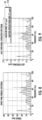
- the torque spectrum and the torsional vibration spectrum of the modified PWM 110 are illustrated over the spectrums of the baseline PWM 10.
- the spectrums of the modified PWM 110 have a plurality of peaks with similar amplitudes.
- the peaks are shifted away from 16 Hz which is a sensitive frequency of the vehicle, as shown in FIG. 6 .
- a number of the peaks have an amplitude around 10 Hz such that these peaks may act as white noise such that the peaks may be imperceptible to an occupant of the vehicle.
- the peaks of the torsional vibration spectrum of the modified PWM 110 may act as white noise such that the peaks may be imperceptible to an occupant of the vehicle.
- the method of canceling vibration can be executed in a controller of the electric motor 20 without the need for vibration mitigation hardware, e.g., vibration isolating engine mounts or a fly wheel.
- the method includes generating an optimized pulse train of pulses for a given duty cycle such that vibration induced by pulsing the electric motor is reduced or completely canceled.
- the pulse trains may be optimized to shift excitation energy of the motor away from frequencies of the FRF of the driven equipment that are sensitive to frequencies of the FRF of the driven equipment that are less sensitive. This shifting of excitation energy may be done in such a way that the overall torsional vibration response of the driven equipment is minimized compared to steady phase pulsation while operating within the limitations of the inverter and maintaining the efficiency gains of from pulsing the electric motor 20.
- the controller of the electric motor 20 can provide signals or provide current to the electric motor 20.
- the method 200 of canceling vibrations may be active whenever the controller pulses the electric motor or may only be active when pulsing the electric motor 20 in a stead PWM fashion would result in unacceptable NVH of the driven equipment.
- the optimized or modified pulse trains for each duty cycle and/or operating condition may be generated and stored in a table or be generated in real time.
- a baseline PWM frequency may be chosen to provide options across a broad duty cycle range. For example, a baseline PWM frequency of 40 Hz may be chosen as a starting point.
- the pulse train may be modeled for several duty cycles from 10% to 90% in increments of 5%, 10%, or 20% and for a variety of motor speeds.
- Each modeled pulse train may have a start time, a stop time, and a pulse torque for each pulse that is optimized to minimize the cost function.
- These modeled pulse trains may be stored in a table such that when a duty cycle is requested from the controller of the electric motor 20, the controller can look up a modeled pulse train for the duty cycle.
- the controller can identify a modeled pulse train based on the requested duty cycle. In some embodiments, the controller can identify a pulse train based on the request torque and another operating condition such as motor speed. When the requested duty cycle has a modeled pulse train, the controller instructs the electric motor 20 to be excited as modeled. When the requested duty cycle is between two modeled pulse trains, the controller may interpolate between the pulse train for a duty cycle above the requested duty cycle and the pulse train for a duty cycle below the requested duty cycle. In some embodiments, the controller may interpolate between pulse trains by identifying the duty cycle closest to the requested duty cycle for which there is a modeled pulse train and increase or decrease a length of each pulse in the modeled pulse train to provide the requested duty cycle.
- adjacent duty cycles may have modeled pulse trains that are dissimilar to one another such that when a new duty cycle is requested, the controller may identify an end point of the previous pulse train or create a breakpoint in the pulse train to switch to a new pulse train for the newly requested duty cycle. If the previous pulse train and the new pulse train are significantly different from one another, e.g., have dissimilar boundaries, the controller may generate a bridge pulse train to switch between the previous pulse train and the new pulse train. The controller may perform a cost function analysis to determine if a bridge pulse train is required or if the previous pulse train can be modified, e.g., pulse lengths modified, to provide the new duty cycle with a lower cost than switching to the new pulse train. However, if the controller determines that an interpolated cost function penalty of staying with the previous pulse train exceeds the interpolated cost function penalty of switching to the new pulse train by a predetermined hysteresis cost value, the controller switches to the new pulse train.
- a method of canceling vibrations from pulsing an electric motor is detailed in accordance with embodiments of the present disclosure and is referred to generally as method 200.
- the method 200 is executed on a controller that provides signals to an electric motor to deliver a target torque to a drive component.
- the method 200 is described in accordance with the model of an electric motor 20 and vehicle 10 of FIG. 5 .
- the drive component may be a driveshaft or axle of a vehicle or may be a driveshaft to rotate a piece of equipment.
- the method 200 may include a controller of the electric motor 20 receiving an input signal requesting a target torque from the electric motor 20 (Step 210).
- the controller analyzes the requested target torque to determine if the target torque is within a continuous operation range of the electric motor 20 (Step 220).
- the continuous operation range may be a range of torques that are at or above the optimal efficiency point of the electric motor 20.
- the continuous operation range may include a range of torques that are below the optimal efficiency point of the electric motor 20. For example, when the optimal efficiency point of the electric motor 20 is 60% of the maximum torque of the electric motor 20, the continuous operation range may be from 40% to 100% of the maximum torque of the electric motor 20.
- the continuous operation range may cover a range of torques at which continuous operation of the electric motor 20 has a greater efficiency than providing a requested torque by pulsing the electric motor 20 to reduce a duty cycle thereof.
- the controller When the requested target torque is within continuous operation range, the controller operates the electric motor 20 to deliver the target torque as a continuous torque (Step 230).
- the controller selects an optimal efficiency torque or point to pulse the electric motor 20 and calculates a duty cycle for the electric motor 20 to deliver the target torque (Step 240).
- the duty cycle is adjusted to set the torque delivered from the electric motor 20 to the target torque while pulsing the electric motor 20. For example, to increase a torque delivered from the electric motor 20, the duty cycle is increased and to decrease a torque delivered from the electric motor 20, the duty cycle is decreased.
- the controller With the duty cycle selected, the controller generates a pulse train of pulses to deliver the target torque in view of the duty cycle and operating conditions (Step 250).
- the generated pulse train is optimized to deliver the target torque while reducing responses within the driven equipment.
- the generated pulse train may include a number of pulses and/or a start time, a stop time, a pulse length, or a torque or amplitude of each pulse in the pulse train.
- the operating conditions may include, but not be limited to, weather, weight of passengers and/or cargo, incline, road conditions, acoustic settings (radio volume), temperature, motor speed (RPM), vehicle speed, velocity, or acceleration.
- generating the pulse train is solely determinate on the calculated duty cycle.
- generating the pulse train may include the controller determining a number of pulses of the pulse train and/or a start time, a stop time, a pulse length, or a torque or amplitude of each pulse in the pulse train in real-time.
- generating the pulse train may include optimizing the generated pulse train based on real-time sensor data of the driven equipment including, but not limited to, vibration sensors, accelerometers, and acoustic sensors.
- the controller pulses the electric motor with the generated pulse train (Step 260).
- the controller may pulse the electric motor 20 with the generated pulse train until a new target torque is received by the controller.
- the controller detailed above may be a standalone controller or may be part of another controller.
- the controller includes a processor and a memory.
- the controller may also include an input to receive input such as a desired torque.
- the controller includes a motor output that is in signal communication with an electric motor to operate the electric motor to provide a target torque.
- the methods detailed above may be stored in the memory of the controller as a non-transitory computer-readable medium that when executed on the processor of the controller cause the controller to execute the methods detailed above including method 200.
Landscapes
- Engineering & Computer Science (AREA)
- Power Engineering (AREA)
- Transportation (AREA)
- Mechanical Engineering (AREA)
- Life Sciences & Earth Sciences (AREA)
- Sustainable Development (AREA)
- Sustainable Energy (AREA)
- Databases & Information Systems (AREA)
- Electric Propulsion And Braking For Vehicles (AREA)
- Control Of Multiple Motors (AREA)
- Control Of Ac Motors In General (AREA)
Applications Claiming Priority (4)
| Application Number | Priority Date | Filing Date | Title |
|---|---|---|---|
| US202163161405P | 2021-03-15 | 2021-03-15 | |
| US202163219441P | 2021-07-08 | 2021-07-08 | |
| PCT/US2022/020444 WO2022197742A1 (en) | 2021-03-15 | 2022-03-15 | Methods of optimizing waveforms for electric motors |
| EP22772091.9A EP4308405A4 (de) | 2021-03-15 | 2022-03-15 | Verfahren zur optimierung von wellenformen für elektromotoren |
Related Parent Applications (2)
| Application Number | Title | Priority Date | Filing Date |
|---|---|---|---|
| EP22772091.9A Division-Into EP4308405A4 (de) | 2021-03-15 | 2022-03-15 | Verfahren zur optimierung von wellenformen für elektromotoren |
| EP22772091.9A Division EP4308405A4 (de) | 2021-03-15 | 2022-03-15 | Verfahren zur optimierung von wellenformen für elektromotoren |
Publications (2)
| Publication Number | Publication Date |
|---|---|
| EP4358397A2 true EP4358397A2 (de) | 2024-04-24 |
| EP4358397A3 EP4358397A3 (de) | 2024-07-10 |
Family
ID=83195219
Family Applications (2)
| Application Number | Title | Priority Date | Filing Date |
|---|---|---|---|
| EP22772091.9A Pending EP4308405A4 (de) | 2021-03-15 | 2022-03-15 | Verfahren zur optimierung von wellenformen für elektromotoren |
| EP24161846.1A Pending EP4358397A3 (de) | 2021-03-15 | 2022-03-15 | Verfahren zur optimierung von wellenformen für elektromotoren |
Family Applications Before (1)
| Application Number | Title | Priority Date | Filing Date |
|---|---|---|---|
| EP22772091.9A Pending EP4308405A4 (de) | 2021-03-15 | 2022-03-15 | Verfahren zur optimierung von wellenformen für elektromotoren |
Country Status (5)
| Country | Link |
|---|---|
| US (1) | US11637513B2 (de) |
| EP (2) | EP4308405A4 (de) |
| JP (1) | JP2024510092A (de) |
| KR (1) | KR20230156335A (de) |
| WO (1) | WO2022197742A1 (de) |
Families Citing this family (15)
| Publication number | Priority date | Publication date | Assignee | Title |
|---|---|---|---|---|
| US12311772B2 (en) | 2018-03-19 | 2025-05-27 | Tula eTechnology, Inc. | Pulse modulated control with field weakening for improved machine efficiency |
| KR102783720B1 (ko) | 2018-03-19 | 2025-03-18 | 툴라 이테크놀로지 아이엔씨. | 펄스 전기 기계 제어 |
| US12609646B2 (en) | 2018-03-19 | 2026-04-21 | Tula eTechnology, Inc. | Boosted converter for pulsed electric machine control |
| JP7644640B2 (ja) * | 2021-03-25 | 2025-03-12 | 株式会社Subaru | 車両制御装置 |
| KR20240025508A (ko) | 2021-06-28 | 2024-02-27 | 툴라 이테크놀로지 아이엔씨. | 전기 기계의 선택적 위상 제어 |
| US11345241B1 (en) | 2021-08-12 | 2022-05-31 | Tula eTechnology, Inc. | Method of optimizing system efficiency for battery powered electric motors |
| EP4497197A4 (de) | 2022-03-22 | 2026-02-18 | Tula Technology Inc | Verzögerungsreduktion für synchronmaschinen mit gepulstem wickelfeld |
| US11888424B1 (en) | 2022-07-18 | 2024-01-30 | Tula eTechnology, Inc. | Methods for improving rate of rise of torque in electric machines with stator current biasing |
| US20240092406A1 (en) * | 2022-09-16 | 2024-03-21 | Matthew Younkins | Method to Manage Autonomous Vehicle Energy |
| US20240239328A1 (en) * | 2023-01-18 | 2024-07-18 | Ford Global Technologies, Llc | Electric machine speed dependent variable frequency pulsed torque control for electric machine |
| US12427870B2 (en) | 2023-02-02 | 2025-09-30 | Ford Global Technologies, Llc | Methods and system for improving electric machine efficiency |
| US12409738B2 (en) * | 2023-02-06 | 2025-09-09 | Ford Global Technologies, Llc | Pulsed torque command with adjustable magnitude for electric machine torque control |
| IT202300004131A1 (it) * | 2023-03-07 | 2024-09-07 | Ferrari Spa | Gruppo assale elettrico per un autoveicolo con un dispositivo di cancellazione di rumore |
| CN118944527A (zh) * | 2023-05-04 | 2024-11-12 | 博格华纳公司 | 变频脉冲电机控制系统 |
| US12370907B2 (en) | 2023-10-17 | 2025-07-29 | Tula eTechnology, Inc. | On-pulse transition times for pulsed controlled electric machines using boost voltages |
Family Cites Families (140)
| Publication number | Priority date | Publication date | Assignee | Title |
|---|---|---|---|---|
| US4441043A (en) | 1980-11-24 | 1984-04-03 | Decesare Dominic | Compound interaction/induction electric rotating machine |
| JPS6189144A (ja) | 1984-10-08 | 1986-05-07 | Nissan Motor Co Ltd | 自動車用故障診断装置 |
| JPH07106073B2 (ja) | 1989-04-19 | 1995-11-13 | 株式会社日立製作所 | モータの減速装置およびこれに用いられるモータ駆動回路あるいはミシンの制御装置 |
| US5099410A (en) | 1990-11-13 | 1992-03-24 | Wisconsin Alumni Research Foundation | Single phase ac power conversion apparatus |
| JP3290481B2 (ja) | 1992-12-03 | 2002-06-10 | 東芝キヤリア株式会社 | 冷凍サイクル制御装置 |
| US5325028A (en) | 1993-03-26 | 1994-06-28 | Storage Technology Corporation | System and method for magnetic tape leader block extraction |
| US6424799B1 (en) | 1993-07-06 | 2002-07-23 | Black & Decker Inc. | Electrical power tool having a motor control circuit for providing control over the torque output of the power tool |
| JP3333793B2 (ja) | 1994-09-22 | 2002-10-15 | サンデン株式会社 | ブラシレスモータ装置 |
| JPH0984208A (ja) | 1995-09-14 | 1997-03-28 | Denso Corp | 電気自動車用制御装置 |
| JP3716534B2 (ja) | 1997-02-27 | 2005-11-16 | 日産自動車株式会社 | モータ制御装置及び電動車両 |
| US6605912B1 (en) | 1998-06-25 | 2003-08-12 | Delphi Technologies, Inc. | Method for controlling a permanent magnet motor |
| FI110040B (fi) | 1998-10-07 | 2002-11-15 | Abb Industry Oy | Vaihtosuuntaajajärjestely |
| JP2001010518A (ja) | 1999-06-25 | 2001-01-16 | Honda Motor Co Ltd | 車両用操舵制御装置 |
| US6493204B1 (en) | 1999-07-09 | 2002-12-10 | Kelsey-Hayes Company | Modulated voltage for a solenoid valve |
| US7453174B1 (en) | 1999-08-10 | 2008-11-18 | American Superconductor Corporation | Superconducting electric motor |
| US6291960B1 (en) | 2000-03-22 | 2001-09-18 | Ford Global Technologies, Inc. | Pulse width modulated motor control system and method for reducing noise vibration and harshness |
| JP2001317353A (ja) | 2000-05-11 | 2001-11-16 | Nissan Motor Co Ltd | 車両用モータファンの制御方法及び装置 |
| DE10048826B4 (de) | 2000-09-29 | 2012-03-01 | Robert Bosch Gmbh | Verfahren und Vorrichtung zur Erfassung alterungsbedingter Veränderungen von technischen Systemen wie Elektromotoren |
| US6528967B2 (en) | 2000-10-17 | 2003-03-04 | Vscf, Inc. | Permanent magnet brushless electric motor system and method of using same |
| JP2005506830A (ja) | 2001-10-25 | 2005-03-03 | コーニンクレッカ フィリップス エレクトロニクス エヌ ヴィ | センサレス直流モータの転流 |
| US6906485B2 (en) | 2001-11-05 | 2005-06-14 | Seagate Technology Llc | Spindle motor control using a current profile to taper current transitions |
| JP3672866B2 (ja) | 2001-12-04 | 2005-07-20 | 松下電器産業株式会社 | モータ駆動装置およびモータ駆動方法 |
| JP3651595B2 (ja) | 2001-12-13 | 2005-05-25 | 株式会社東芝 | 洗濯機のインバータ装置及び洗濯乾燥機のインバータ装置 |
| US7034422B2 (en) | 2002-05-24 | 2006-04-25 | Virginia Tech Intellectual Properties, Inc. | Radial-axial electromagnetic flux electric motor, coaxial electromagnetic flux electric motor, and rotor for same |
| US6829556B2 (en) | 2003-02-13 | 2004-12-07 | General Electric Company | Method and system for detecting incipient failures in a traction system |
| US6954044B2 (en) | 2003-12-11 | 2005-10-11 | Honeywell International Inc. | Electric motor with speed control |
| US7259664B1 (en) | 2004-06-16 | 2007-08-21 | Chahee Peter Cho | Sensorless fuel level and oil change indicators |
| US7558655B2 (en) | 2004-09-10 | 2009-07-07 | Ford Global Technologies, Llc | Prognostic method and system for hybrid and electric vehicle components |
| DE102004055128A1 (de) | 2004-11-16 | 2006-06-01 | Volkswagen Ag | Verfahren zur Steuerung eines Betriebs eines Hybridkraftfahrzeugs sowie Hybridfahrzeug |
| JP4254738B2 (ja) | 2005-03-31 | 2009-04-15 | 株式会社デンソー | 車両用発電機の発電制御装置 |
| US7190143B2 (en) | 2005-05-27 | 2007-03-13 | Rockwell Automation Technologies, Inc. | Pulse width modulation (PWM) rectifier with variable switching frequency |
| DE112005003604T5 (de) | 2005-06-10 | 2008-04-30 | Toyota Jidosha Kabushiki Kaisha, Toyota | Rotierende elektrische Maschine |
| US7411801B2 (en) | 2005-12-14 | 2008-08-12 | Gm Global Technology Operations, Inc. | Method and apparatus for controlling voltage linearity of voltage source inverters |
| JP4736875B2 (ja) | 2006-03-14 | 2011-07-27 | 株式会社デンソー | ファンモータ駆動装置及びファンモータ駆動方法 |
| CN100355196C (zh) | 2006-03-29 | 2007-12-12 | 北京航空航天大学 | 小电枢电感高速永磁无刷直流电动机无位置传感器控制系统 |
| JP4802849B2 (ja) | 2006-05-09 | 2011-10-26 | トヨタ自動車株式会社 | モータ駆動装置 |
| US7854683B2 (en) | 2006-06-08 | 2010-12-21 | Chrysler Group Llc | Torque converter clutch control |
| JP2008079686A (ja) | 2006-09-26 | 2008-04-10 | Hitachi Appliances Inc | 洗濯機および洗濯乾燥機 |
| JP5167631B2 (ja) | 2006-11-30 | 2013-03-21 | 株式会社デンソー | モータの制御方法及びそれを利用するモータ制御装置 |
| US20110089774A1 (en) | 2007-01-30 | 2011-04-21 | Kramer Dennis A | Transverse flux motor with integral cooling |
| US7479723B2 (en) | 2007-01-30 | 2009-01-20 | Gm Global Technology Operations, Inc. | Permanent magnet machine rotor |
| JP2008285075A (ja) | 2007-05-18 | 2008-11-27 | Toyota Motor Corp | 車両および車両の故障診断方法 |
| US8903577B2 (en) * | 2009-10-30 | 2014-12-02 | Lsi Industries, Inc. | Traction system for electrically powered vehicles |
| US20090045691A1 (en) | 2007-08-17 | 2009-02-19 | Kura Laboratory Corporation | Field controllable rotating electric machine system with magnetic excitation part |
| JP4452735B2 (ja) | 2007-09-05 | 2010-04-21 | 本田技研工業株式会社 | 昇圧コンバータの制御装置および制御方法 |
| US7616466B2 (en) | 2007-09-12 | 2009-11-10 | Gm Global Technology Operations, Inc. | Three phase inverter with improved loss distribution |
| CN101803176B (zh) | 2007-09-18 | 2013-03-13 | 株式会社东芝 | 可变磁通驱动系统 |
| US8084972B2 (en) | 2007-11-16 | 2011-12-27 | Honeywell International Inc. | Dual lane control of a permanent magnet brushless motor using non-trapezoidal commutation control |
| US7888905B2 (en) | 2008-01-11 | 2011-02-15 | GM Global Technology Operations LLC | Method and system for controlling a power inverter in electric drives |
| US7791521B2 (en) | 2008-04-01 | 2010-09-07 | Silicon Laboratories, Inc. | System and method of changing a PWM power spectrum |
| US8131447B2 (en) | 2008-07-11 | 2012-03-06 | Tula Technology, Inc. | Internal combustion engine control for improved fuel efficiency |
| US7577511B1 (en) | 2008-07-11 | 2009-08-18 | Tula Technology, Inc. | Internal combustion engine control for improved fuel efficiency |
| US8616181B2 (en) | 2008-07-11 | 2013-12-31 | Tula Technology, Inc. | Internal combustion engine control for improved fuel efficiency |
| US8701628B2 (en) | 2008-07-11 | 2014-04-22 | Tula Technology, Inc. | Internal combustion engine control for improved fuel efficiency |
| KR20100021146A (ko) | 2008-08-14 | 2010-02-24 | 박계정 | 모터의 최대효율추적제어 시스템 및 그 방법 |
| US8453770B2 (en) | 2009-01-29 | 2013-06-04 | Tesla Motors, Inc. | Dual motor drive and control system for an electric vehicle |
| US7808415B1 (en) | 2009-03-25 | 2010-10-05 | Acco Semiconductor, Inc. | Sigma-delta modulator including truncation and applications thereof |
| JP5304894B2 (ja) | 2009-05-29 | 2013-10-02 | トヨタ自動車株式会社 | 交流電動機の制御装置および制御方法 |
| JP5183594B2 (ja) | 2009-07-31 | 2013-04-17 | 日立オートモティブシステムズ株式会社 | モータの制御装置及びそれを備えたモータシステム |
| US20110130916A1 (en) | 2009-12-01 | 2011-06-02 | Ise Corporation | Location Based Vehicle Data Logging and Diagnostic System and Method |
| GB2472297B (en) | 2010-07-19 | 2014-04-23 | Protean Electric Ltd | Electric motor |
| US8536818B2 (en) | 2010-11-04 | 2013-09-17 | GM Global Technology Operations LLC | Control of a traction power inverter module in a vehicle having an electric traction motor |
| US8446117B2 (en) | 2011-01-03 | 2013-05-21 | GM Global Technology Operations LLC | Methods, systems and apparatus for adjusting duty cycle of pulse width modulated (PWM) waveforms |
| US8624531B2 (en) | 2011-02-24 | 2014-01-07 | Deere & Company | Method and system for evaluating electrical connections between a motor controller and motor |
| WO2012120682A1 (ja) | 2011-03-10 | 2012-09-13 | パイオニア株式会社 | 効率マップ生成装置、効率マップ生成方法、およびプログラム |
| CN103477546B (zh) | 2011-04-19 | 2016-04-20 | 丰田自动车株式会社 | 升压变换器的控制装置 |
| US9050894B2 (en) | 2011-07-06 | 2015-06-09 | General Electric Company | System and method for predicting mechanical failure of a motor |
| JP5633652B2 (ja) | 2011-08-03 | 2014-12-03 | トヨタ自動車株式会社 | 電動機駆動システム |
| CN102381265A (zh) | 2011-10-14 | 2012-03-21 | 奇瑞汽车股份有限公司 | 一种汽车智能故障诊断预警及报警方法 |
| EP2605398A4 (de) | 2011-10-17 | 2014-04-30 | Panasonic Corp | Motorantriebssystem und steuerungsverfahren dafür |
| WO2013069473A1 (ja) | 2011-11-07 | 2013-05-16 | 株式会社ジェイテクト | 電動パワーステアリング装置 |
| US20130134912A1 (en) | 2011-11-30 | 2013-05-30 | Caterpillar, Inc. | Switched Reluctance Machine Natural Transition between Current Regulation and Single Pulse Operation |
| JP5941669B2 (ja) | 2011-12-20 | 2016-06-29 | 東芝三菱電機産業システム株式会社 | インパルス電圧発生装置 |
| JP5681817B2 (ja) | 2011-12-26 | 2015-03-11 | 川崎重工業株式会社 | 電動式乗り物の診断方法及びシステム |
| US8768563B2 (en) | 2012-01-24 | 2014-07-01 | Eaton Corporation | Electric vehicle supply equipment testing apparatus |
| US8907604B2 (en) * | 2012-02-07 | 2014-12-09 | Ford Global Technologies, Llc | PWM frequency pattern optimization for NVH |
| GB2499657B (en) | 2012-02-27 | 2018-07-11 | Ford Global Tech Llc | Vehicle speed control apparatus and method |
| US9729016B1 (en) | 2012-03-20 | 2017-08-08 | Linear Labs, Inc. | Multi-tunnel electric motor/generator |
| JP2013207914A (ja) | 2012-03-28 | 2013-10-07 | Toyota Motor Corp | 電圧変換装置の制御装置 |
| FR2989479B1 (fr) | 2012-04-13 | 2014-03-28 | Renault Sa | Systeme et procede de commande d'une machine electrique equipant un vehicule electrique |
| US9046559B2 (en) | 2012-05-09 | 2015-06-02 | Curtis Instruments, Inc. | Isolation monitor |
| GB201218674D0 (en) | 2012-10-17 | 2012-11-28 | Trw Ltd | Control strategy for a motor of an electric assisted steering system |
| US9322480B2 (en) | 2012-11-12 | 2016-04-26 | Ford Global Technologies, Llc | Turbocharger arrangement and set of feedbacks for electric actuator control |
| US9610397B2 (en) | 2012-11-20 | 2017-04-04 | Medimop Medical Projects Ltd. | System and method to distribute power to both an inertial device and a voltage sensitive device from a single current limited power source |
| KR102027123B1 (ko) | 2013-02-07 | 2019-11-04 | 존슨 컨트롤스 테크놀러지 컴퍼니 | 가변속 드라이브를 위한 하이브리드 펄스 폭 변조방법 |
| CN104052343B (zh) | 2013-03-14 | 2016-12-28 | 中山大洋电机股份有限公司 | 一种用来替换psc电机的ecm电机力矩自动校正的方法 |
| GB201308249D0 (en) | 2013-05-08 | 2013-06-12 | Trw Ltd | Method of controlling a motor of an electric power assisted steering system |
| US9240740B2 (en) | 2013-05-30 | 2016-01-19 | The Boeing Company | Active voltage controller for an electric motor |
| JP5842875B2 (ja) | 2013-07-19 | 2016-01-13 | トヨタ自動車株式会社 | 車両および車両の制御方法 |
| DE112013007529T5 (de) | 2013-10-23 | 2016-07-14 | Mitsubishi Electric Corporation | Motorsteuervorrichtung und Motorsteuerverfahren |
| DE102013223704A1 (de) | 2013-11-20 | 2015-05-21 | Bayerische Motoren Werke Aktiengesellschaft | Fahrzeug mit einem Ethernet-Bussystem und Verfahren zum Betreiben eines solchen Bussystems |
| US10017892B2 (en) | 2014-02-21 | 2018-07-10 | Samsung Electronics Co., Ltd. | Washing apparatus and controlling method thereof |
| US10261670B2 (en) | 2014-03-14 | 2019-04-16 | Atronix Acquisition Corp. | Zooming user interface for a material handling control system |
| US9495814B2 (en) | 2014-06-19 | 2016-11-15 | Atieva, Inc. | Vehicle fault early warning system |
| US9758044B2 (en) | 2014-10-02 | 2017-09-12 | Ford Global Technologies, Llc | Bus leakage resistance estimation for electrical isolation testing and diagnostics |
| US9948173B1 (en) | 2014-11-18 | 2018-04-17 | The Board Of Trustees Of The University Of Alabama | Systems and methods for short-time fourier transform spectrogram based and sinusoidality based control |
| JP6524546B2 (ja) * | 2015-01-12 | 2019-06-05 | トゥラ テクノロジー インコーポレイテッドTula Technology,Inc. | スキップファイアエンジン制御システムにおける騒音、振動およびハーシュネスの低減 |
| US10344692B2 (en) * | 2015-01-12 | 2019-07-09 | Tula Technology, Inc. | Adaptive torque mitigation by micro-hybrid system |
| US10060368B2 (en) | 2015-01-12 | 2018-08-28 | Tula Technology, Inc. | Engine torque smoothing |
| KR101736819B1 (ko) | 2015-02-11 | 2017-05-17 | 엘지전자 주식회사 | 모터 구동 장치 |
| CN104716754A (zh) | 2015-02-16 | 2015-06-17 | 武汉华大新型电机科技股份有限公司 | 提升电机转矩密度方法及径向、轴向磁通并联永磁电机 |
| CN204589885U (zh) | 2015-04-14 | 2015-08-26 | 江苏大学 | 一种纯电动道路清扫车车载监控系统 |
| US9698722B2 (en) | 2015-06-19 | 2017-07-04 | Deere & Company | Method and inverter with thermal management for controlling an electric machine |
| JP6390535B2 (ja) | 2015-06-26 | 2018-09-19 | 株式会社デンソー | 電力変換制御装置 |
| KR102383147B1 (ko) | 2015-08-17 | 2022-04-06 | 대우조선해양 주식회사 | 상향조정 조립식 잭킹 시스템 |
| KR101724903B1 (ko) | 2015-09-16 | 2017-04-07 | 현대자동차주식회사 | 친환경 차량의 모터 시스템 제어 방법 |
| US20170087990A1 (en) | 2015-09-29 | 2017-03-30 | General Electric Company | System and method for predicting mechanical failure |
| CN105196877B (zh) | 2015-09-30 | 2017-09-08 | 上海交通大学 | 电动汽车高压电系统健康状态诊断预警电路及方法 |
| KR101704279B1 (ko) | 2015-11-05 | 2017-02-07 | 현대자동차주식회사 | Dct의 클러치 고장진단방법 |
| CN205229379U (zh) | 2015-11-09 | 2016-05-11 | 上海凌翼动力科技有限公司 | 自适应的电动汽车高压电安全故障诊断预警定位监测系统 |
| JP6205588B1 (ja) | 2015-12-22 | 2017-10-04 | パナソニックIpマネジメント株式会社 | モータ制御装置のカスタマイズ方法、およびモータ制御装置 |
| CN105610288B (zh) | 2016-01-26 | 2018-02-27 | 江苏大学 | 一种永磁转矩和磁阻转矩分离型电机及最优效率控制方法 |
| US9630614B1 (en) | 2016-01-28 | 2017-04-25 | Miq Llc | Modular power plants for machines |
| JP6653011B2 (ja) | 2016-02-25 | 2020-02-26 | 株式会社日立製作所 | アキシャルギャップ型回転電機 |
| JP6458762B2 (ja) | 2016-04-28 | 2019-01-30 | トヨタ自動車株式会社 | 自動車 |
| US20170331402A1 (en) | 2016-05-10 | 2017-11-16 | General Electric Company | System and method for vehicle diagnostics |
| JP6699348B2 (ja) | 2016-05-20 | 2020-05-27 | 株式会社デンソー | 電力変換装置の制御装置 |
| KR101916060B1 (ko) | 2016-08-11 | 2018-11-07 | 현대자동차 주식회사 | 인버터 고장 예지 장치 및 방법 |
| JP6193456B1 (ja) | 2016-08-25 | 2017-09-06 | 株式会社ソシオリカ | 同期電動機 |
| US20180276913A1 (en) | 2016-09-30 | 2018-09-27 | Faraday&Future Inc. | Remote vehicle network monitoring and failure prediction system |
| US10500965B2 (en) | 2016-12-01 | 2019-12-10 | Ford Global Technologies, Llc | Dithering a pulse width modulated base frequency to reduce EV noise |
| CN107067780A (zh) | 2016-12-06 | 2017-08-18 | 天津泓耘财科技发展有限公司 | 一种汽车远程监控预警系统 |
| CN106932208B (zh) | 2017-03-29 | 2020-03-06 | 北京新能源汽车股份有限公司 | 电动汽车驱动系统的输出扭矩监测方法、装置及电动汽车 |
| US10696164B2 (en) | 2017-05-18 | 2020-06-30 | Ford Global Technologies, Llc | Optimizing regenerative braking efficiency in a hybrid vehicle |
| CN207129052U (zh) | 2017-09-01 | 2018-03-23 | 路子霖 | 一种智能电动车 |
| US10381968B2 (en) | 2017-12-05 | 2019-08-13 | Otis Elevator Company | Converter pulse width modulation strategies for three phase regenerative drives |
| CN108216026A (zh) | 2017-12-29 | 2018-06-29 | 杨运华 | 一种电动汽车安全预警系统及预警方法 |
| JP7047461B2 (ja) * | 2018-02-28 | 2022-04-05 | 株式会社デンソー | 制御装置 |
| US10944352B2 (en) | 2018-03-19 | 2021-03-09 | Tula eTechnology, Inc. | Boosted converter for pulsed electric machine control |
| KR102783720B1 (ko) * | 2018-03-19 | 2025-03-18 | 툴라 이테크놀로지 아이엔씨. | 펄스 전기 기계 제어 |
| US11133767B2 (en) | 2018-03-19 | 2021-09-28 | Tula eTechnology, Inc. | Pulsed electric machine control using tables |
| CN108445386A (zh) | 2018-05-24 | 2018-08-24 | 顺科新能源技术股份有限公司 | 一种电动汽车功率继电器故障检测系统及其方法 |
| US10476421B1 (en) | 2018-08-28 | 2019-11-12 | Caterpillar Inc. | Optimized switched reluctance phase current control in a continuous conduction mode |
| US10550776B1 (en) | 2018-11-13 | 2020-02-04 | Ford Global Technologies, Llc | Systems and methods for reducing vehicle valve degradation |
| JP7135929B2 (ja) | 2019-02-20 | 2022-09-13 | トヨタ自動車株式会社 | 制動力制御装置 |
| JP7153168B2 (ja) * | 2019-03-05 | 2022-10-14 | 株式会社デンソー | 電動機の制御装置 |
| JP6679200B1 (ja) * | 2019-03-25 | 2020-04-15 | マレリ株式会社 | モータ駆動車両の制御装置、モータ駆動車両の制御方法およびモータ駆動車両の制御プログラム |
| GB2583343B (en) | 2019-04-23 | 2023-11-29 | Trw Ltd | An electric motor apparatus |
| GB2583947B (en) | 2019-05-15 | 2023-11-29 | Trw Ltd | An electric motor apparatus |
| US20210351733A1 (en) | 2020-05-05 | 2021-11-11 | Tula eTechnology, Inc. | Pulsed electric machine control |
-
2022
- 2022-03-15 US US17/695,663 patent/US11637513B2/en active Active
- 2022-03-15 KR KR1020237030317A patent/KR20230156335A/ko active Pending
- 2022-03-15 EP EP22772091.9A patent/EP4308405A4/de active Pending
- 2022-03-15 WO PCT/US2022/020444 patent/WO2022197742A1/en not_active Ceased
- 2022-03-15 EP EP24161846.1A patent/EP4358397A3/de active Pending
- 2022-03-15 JP JP2023550025A patent/JP2024510092A/ja active Pending
Also Published As
| Publication number | Publication date |
|---|---|
| EP4308405A4 (de) | 2024-07-10 |
| EP4358397A3 (de) | 2024-07-10 |
| JP2024510092A (ja) | 2024-03-06 |
| US20220294368A1 (en) | 2022-09-15 |
| WO2022197742A1 (en) | 2022-09-22 |
| KR20230156335A (ko) | 2023-11-14 |
| EP4308405A1 (de) | 2024-01-24 |
| US11637513B2 (en) | 2023-04-25 |
Similar Documents
| Publication | Publication Date | Title |
|---|---|---|
| US11637513B2 (en) | Methods of optimizing waveforms for electric motors | |
| US20230011334A1 (en) | Methods of reducing vibrations for electric motors | |
| US20230268852A1 (en) | Methods of optimizing waveforms for electric motors | |
| US20250260351A1 (en) | Pulsed electric machine control | |
| US8474801B2 (en) | Solenoid driving device and active vibration isolating support device equipped with the same | |
| CN103140698B (zh) | 主动减振装置、车辆、主动减振装置的控制方法 | |
| KR20260003351A (ko) | 노칭 필터가 구비된 펄싱된 전기 머신 제어 | |
| US20230253911A1 (en) | Pulsed electric machine control | |
| US12424962B2 (en) | Pulsed electric machine control with soft start and end | |
| US20240022199A1 (en) | Pulsed electric machine control with soft start and end | |
| JP5494509B2 (ja) | 車載用電気システム | |
| CN102917936A (zh) | 用于减小驱动马达的输出轴上的振动的方法和装置 | |
| CN116890652A (zh) | 电动车辆的控制装置 | |
| JP5994231B2 (ja) | 駆動装置の制御装置 | |
| JP2018019528A (ja) | スイッチトリラクタンスモータの制御装置 | |
| GB2576480A (en) | Control system and method | |
| KR102869285B1 (ko) | 차량의 디퍼렌셜 기어 진동 제어 장치 및 방법 | |
| JP2641166B2 (ja) | エンジンのトルク制御装置 | |
| US20250373187A1 (en) | Pulsed electric machine control with soft start and end | |
| JPH0970200A (ja) | 内燃機関の補助動力制御装置 | |
| EP4559086A1 (de) | Gepulste elektrische maschinensteuerung mit sanftem start und ende | |
| JP2009103010A (ja) | 車両用制御装置 | |
| JP2025093162A (ja) | 制振制御装置 | |
| JP2001342864A (ja) | エンジンのトルク変動抑制装置 | |
| JP2009102996A (ja) | スロットルバルブの制御装置、制御方法、その方法を実現させるプログラムおよびそのプログラムを記録した記録媒体 |
Legal Events
| Date | Code | Title | Description |
|---|---|---|---|
| PUAI | Public reference made under article 153(3) epc to a published international application that has entered the european phase |
Free format text: ORIGINAL CODE: 0009012 |
|
| STAA | Information on the status of an ep patent application or granted ep patent |
Free format text: STATUS: REQUEST FOR EXAMINATION WAS MADE |
|
| 17P | Request for examination filed |
Effective date: 20240306 |
|
| AC | Divisional application: reference to earlier application |
Ref document number: 4308405 Country of ref document: EP Kind code of ref document: P |
|
| AK | Designated contracting states |
Kind code of ref document: A2 Designated state(s): AL AT BE BG CH CY CZ DE DK EE ES FI FR GB GR HR HU IE IS IT LI LT LU LV MC MK MT NL NO PL PT RO RS SE SI SK SM TR |
|
| REG | Reference to a national code |
Ref country code: DE Ref legal event code: R079 Free format text: PREVIOUS MAIN CLASS: H02P0029500000 Ipc: H02P0023020000 |
|
| PUAL | Search report despatched |
Free format text: ORIGINAL CODE: 0009013 |
|
| AK | Designated contracting states |
Kind code of ref document: A3 Designated state(s): AL AT BE BG CH CY CZ DE DK EE ES FI FR GB GR HR HU IE IS IT LI LT LU LV MC MK MT NL NO PL PT RO RS SE SI SK SM TR |
|
| RIC1 | Information provided on ipc code assigned before grant |
Ipc: H02P 6/10 20060101ALI20240605BHEP Ipc: B60L 50/60 20190101ALI20240605BHEP Ipc: B60L 15/20 20060101ALI20240605BHEP Ipc: B60L 15/08 20060101ALI20240605BHEP Ipc: H02P 23/14 20060101ALI20240605BHEP Ipc: H02P 23/00 20160101ALI20240605BHEP Ipc: H02P 21/18 20160101ALI20240605BHEP Ipc: H02P 6/08 20160101ALI20240605BHEP Ipc: H02P 21/14 20160101ALI20240605BHEP Ipc: H02P 21/00 20160101ALI20240605BHEP Ipc: H02P 27/08 20060101ALI20240605BHEP Ipc: H02P 21/02 20060101ALI20240605BHEP Ipc: H02P 23/02 20060101AFI20240605BHEP |
|
| STAA | Information on the status of an ep patent application or granted ep patent |
Free format text: STATUS: EXAMINATION IS IN PROGRESS |
|
| 17Q | First examination report despatched |
Effective date: 20251114 |