EP4288708B1 - Verfahren zur bestimmung einer leckage in einem wasserheizsystem und wasserheizsystem - Google Patents
Verfahren zur bestimmung einer leckage in einem wasserheizsystem und wasserheizsystem Download PDFInfo
- Publication number
- EP4288708B1 EP4288708B1 EP22707843.3A EP22707843A EP4288708B1 EP 4288708 B1 EP4288708 B1 EP 4288708B1 EP 22707843 A EP22707843 A EP 22707843A EP 4288708 B1 EP4288708 B1 EP 4288708B1
- Authority
- EP
- European Patent Office
- Prior art keywords
- water
- pressure
- sensor data
- heating system
- heating circuit
- Prior art date
- Legal status (The legal status is an assumption and is not a legal conclusion. Google has not performed a legal analysis and makes no representation as to the accuracy of the status listed.)
- Active
Links
Images
Classifications
-
- F—MECHANICAL ENGINEERING; LIGHTING; HEATING; WEAPONS; BLASTING
- F28—HEAT EXCHANGE IN GENERAL
- F28D—HEAT-EXCHANGE APPARATUS, NOT PROVIDED FOR IN ANOTHER SUBCLASS, IN WHICH THE HEAT-EXCHANGE MEDIA DO NOT COME INTO DIRECT CONTACT
- F28D20/00—Heat storage plants or apparatus in general; Regenerative heat-exchange apparatus not covered by groups F28D17/00 or F28D19/00
- F28D20/0034—Heat storage plants or apparatus in general; Regenerative heat-exchange apparatus not covered by groups F28D17/00 or F28D19/00 using liquid heat storage material
-
- F—MECHANICAL ENGINEERING; LIGHTING; HEATING; WEAPONS; BLASTING
- F24—HEATING; RANGES; VENTILATING
- F24D—DOMESTIC- OR SPACE-HEATING SYSTEMS, e.g. CENTRAL HEATING SYSTEMS; DOMESTIC HOT-WATER SUPPLY SYSTEMS; ELEMENTS OR COMPONENTS THEREFOR
- F24D19/00—Details
- F24D19/10—Arrangement or mounting of control or safety devices
- F24D19/1006—Arrangement or mounting of control or safety devices for water heating systems
- F24D19/1051—Arrangement or mounting of control or safety devices for water heating systems for domestic hot water
-
- E—FIXED CONSTRUCTIONS
- E03—WATER SUPPLY; SEWERAGE
- E03B—INSTALLATIONS OR METHODS FOR OBTAINING, COLLECTING, OR DISTRIBUTING WATER
- E03B7/00—Water main or service pipe systems
- E03B7/003—Arrangement for testing of watertightness of water supply conduits
-
- E—FIXED CONSTRUCTIONS
- E03—WATER SUPPLY; SEWERAGE
- E03B—INSTALLATIONS OR METHODS FOR OBTAINING, COLLECTING, OR DISTRIBUTING WATER
- E03B7/00—Water main or service pipe systems
- E03B7/07—Arrangement of devices, e.g. filters, flow controls, measuring devices, siphons or valves, in the pipe systems
- E03B7/071—Arrangement of safety devices in domestic pipe systems, e.g. devices for automatic shut-off
-
- F—MECHANICAL ENGINEERING; LIGHTING; HEATING; WEAPONS; BLASTING
- F24—HEATING; RANGES; VENTILATING
- F24D—DOMESTIC- OR SPACE-HEATING SYSTEMS, e.g. CENTRAL HEATING SYSTEMS; DOMESTIC HOT-WATER SUPPLY SYSTEMS; ELEMENTS OR COMPONENTS THEREFOR
- F24D11/00—Central heating systems using heat accumulated in storage masses
- F24D11/002—Central heating systems using heat accumulated in storage masses water heating system
- F24D11/003—Central heating systems using heat accumulated in storage masses water heating system combined with solar energy
-
- F—MECHANICAL ENGINEERING; LIGHTING; HEATING; WEAPONS; BLASTING
- F24—HEATING; RANGES; VENTILATING
- F24D—DOMESTIC- OR SPACE-HEATING SYSTEMS, e.g. CENTRAL HEATING SYSTEMS; DOMESTIC HOT-WATER SUPPLY SYSTEMS; ELEMENTS OR COMPONENTS THEREFOR
- F24D11/00—Central heating systems using heat accumulated in storage masses
- F24D11/002—Central heating systems using heat accumulated in storage masses water heating system
- F24D11/004—Central heating systems using heat accumulated in storage masses water heating system with conventional supplementary heat source
-
- F—MECHANICAL ENGINEERING; LIGHTING; HEATING; WEAPONS; BLASTING
- F24—HEATING; RANGES; VENTILATING
- F24D—DOMESTIC- OR SPACE-HEATING SYSTEMS, e.g. CENTRAL HEATING SYSTEMS; DOMESTIC HOT-WATER SUPPLY SYSTEMS; ELEMENTS OR COMPONENTS THEREFOR
- F24D11/00—Central heating systems using heat accumulated in storage masses
- F24D11/02—Central heating systems using heat accumulated in storage masses using heat pumps
- F24D11/0214—Central heating systems using heat accumulated in storage masses using heat pumps water heating system
- F24D11/0228—Central heating systems using heat accumulated in storage masses using heat pumps water heating system combined with conventional heater
-
- F—MECHANICAL ENGINEERING; LIGHTING; HEATING; WEAPONS; BLASTING
- F24—HEATING; RANGES; VENTILATING
- F24D—DOMESTIC- OR SPACE-HEATING SYSTEMS, e.g. CENTRAL HEATING SYSTEMS; DOMESTIC HOT-WATER SUPPLY SYSTEMS; ELEMENTS OR COMPONENTS THEREFOR
- F24D17/00—Domestic hot-water supply systems
- F24D17/0015—Domestic hot-water supply systems using solar energy
-
- F—MECHANICAL ENGINEERING; LIGHTING; HEATING; WEAPONS; BLASTING
- F24—HEATING; RANGES; VENTILATING
- F24D—DOMESTIC- OR SPACE-HEATING SYSTEMS, e.g. CENTRAL HEATING SYSTEMS; DOMESTIC HOT-WATER SUPPLY SYSTEMS; ELEMENTS OR COMPONENTS THEREFOR
- F24D17/00—Domestic hot-water supply systems
- F24D17/0026—Domestic hot-water supply systems with conventional heating means
-
- F—MECHANICAL ENGINEERING; LIGHTING; HEATING; WEAPONS; BLASTING
- F24—HEATING; RANGES; VENTILATING
- F24D—DOMESTIC- OR SPACE-HEATING SYSTEMS, e.g. CENTRAL HEATING SYSTEMS; DOMESTIC HOT-WATER SUPPLY SYSTEMS; ELEMENTS OR COMPONENTS THEREFOR
- F24D17/00—Domestic hot-water supply systems
- F24D17/02—Domestic hot-water supply systems using heat pumps
-
- F—MECHANICAL ENGINEERING; LIGHTING; HEATING; WEAPONS; BLASTING
- F24—HEATING; RANGES; VENTILATING
- F24D—DOMESTIC- OR SPACE-HEATING SYSTEMS, e.g. CENTRAL HEATING SYSTEMS; DOMESTIC HOT-WATER SUPPLY SYSTEMS; ELEMENTS OR COMPONENTS THEREFOR
- F24D19/00—Details
- F24D19/10—Arrangement or mounting of control or safety devices
- F24D19/1006—Arrangement or mounting of control or safety devices for water heating systems
- F24D19/1051—Arrangement or mounting of control or safety devices for water heating systems for domestic hot water
- F24D19/1054—Arrangement or mounting of control or safety devices for water heating systems for domestic hot water the system uses a heat pump
-
- F—MECHANICAL ENGINEERING; LIGHTING; HEATING; WEAPONS; BLASTING
- F24—HEATING; RANGES; VENTILATING
- F24D—DOMESTIC- OR SPACE-HEATING SYSTEMS, e.g. CENTRAL HEATING SYSTEMS; DOMESTIC HOT-WATER SUPPLY SYSTEMS; ELEMENTS OR COMPONENTS THEREFOR
- F24D19/00—Details
- F24D19/10—Arrangement or mounting of control or safety devices
- F24D19/1006—Arrangement or mounting of control or safety devices for water heating systems
- F24D19/1051—Arrangement or mounting of control or safety devices for water heating systems for domestic hot water
- F24D19/1057—Arrangement or mounting of control or safety devices for water heating systems for domestic hot water the system uses solar energy
-
- F—MECHANICAL ENGINEERING; LIGHTING; HEATING; WEAPONS; BLASTING
- F24—HEATING; RANGES; VENTILATING
- F24D—DOMESTIC- OR SPACE-HEATING SYSTEMS, e.g. CENTRAL HEATING SYSTEMS; DOMESTIC HOT-WATER SUPPLY SYSTEMS; ELEMENTS OR COMPONENTS THEREFOR
- F24D19/00—Details
- F24D19/10—Arrangement or mounting of control or safety devices
- F24D19/1006—Arrangement or mounting of control or safety devices for water heating systems
- F24D19/1066—Arrangement or mounting of control or safety devices for water heating systems for the combination of central heating and domestic hot water
- F24D19/1072—Arrangement or mounting of control or safety devices for water heating systems for the combination of central heating and domestic hot water the system uses a heat pump
-
- F—MECHANICAL ENGINEERING; LIGHTING; HEATING; WEAPONS; BLASTING
- F24—HEATING; RANGES; VENTILATING
- F24D—DOMESTIC- OR SPACE-HEATING SYSTEMS, e.g. CENTRAL HEATING SYSTEMS; DOMESTIC HOT-WATER SUPPLY SYSTEMS; ELEMENTS OR COMPONENTS THEREFOR
- F24D19/00—Details
- F24D19/10—Arrangement or mounting of control or safety devices
- F24D19/1006—Arrangement or mounting of control or safety devices for water heating systems
- F24D19/1066—Arrangement or mounting of control or safety devices for water heating systems for the combination of central heating and domestic hot water
- F24D19/1075—Arrangement or mounting of control or safety devices for water heating systems for the combination of central heating and domestic hot water the system uses solar energy
-
- F—MECHANICAL ENGINEERING; LIGHTING; HEATING; WEAPONS; BLASTING
- F24—HEATING; RANGES; VENTILATING
- F24H—FLUID HEATERS, e.g. WATER OR AIR HEATERS, HAVING HEAT-GENERATING MEANS, e.g. HEAT PUMPS, IN GENERAL
- F24H15/00—Control of fluid heaters
- F24H15/10—Control of fluid heaters characterised by the purpose of the control
- F24H15/12—Preventing or detecting fluid leakage
-
- F—MECHANICAL ENGINEERING; LIGHTING; HEATING; WEAPONS; BLASTING
- F24—HEATING; RANGES; VENTILATING
- F24H—FLUID HEATERS, e.g. WATER OR AIR HEATERS, HAVING HEAT-GENERATING MEANS, e.g. HEAT PUMPS, IN GENERAL
- F24H15/00—Control of fluid heaters
- F24H15/10—Control of fluid heaters characterised by the purpose of the control
- F24H15/156—Reducing the quantity of energy consumed; Increasing efficiency
-
- F—MECHANICAL ENGINEERING; LIGHTING; HEATING; WEAPONS; BLASTING
- F24—HEATING; RANGES; VENTILATING
- F24H—FLUID HEATERS, e.g. WATER OR AIR HEATERS, HAVING HEAT-GENERATING MEANS, e.g. HEAT PUMPS, IN GENERAL
- F24H15/00—Control of fluid heaters
- F24H15/10—Control of fluid heaters characterised by the purpose of the control
- F24H15/174—Supplying heated water with desired temperature or desired range of temperature
-
- F—MECHANICAL ENGINEERING; LIGHTING; HEATING; WEAPONS; BLASTING
- F24—HEATING; RANGES; VENTILATING
- F24H—FLUID HEATERS, e.g. WATER OR AIR HEATERS, HAVING HEAT-GENERATING MEANS, e.g. HEAT PUMPS, IN GENERAL
- F24H15/00—Control of fluid heaters
- F24H15/20—Control of fluid heaters characterised by control inputs
- F24H15/212—Temperature of the water
- F24H15/223—Temperature of the water in the water storage tank
- F24H15/225—Temperature of the water in the water storage tank at different heights of the tank
-
- F—MECHANICAL ENGINEERING; LIGHTING; HEATING; WEAPONS; BLASTING
- F24—HEATING; RANGES; VENTILATING
- F24H—FLUID HEATERS, e.g. WATER OR AIR HEATERS, HAVING HEAT-GENERATING MEANS, e.g. HEAT PUMPS, IN GENERAL
- F24H15/00—Control of fluid heaters
- F24H15/20—Control of fluid heaters characterised by control inputs
- F24H15/238—Flow rate
-
- F—MECHANICAL ENGINEERING; LIGHTING; HEATING; WEAPONS; BLASTING
- F24—HEATING; RANGES; VENTILATING
- F24H—FLUID HEATERS, e.g. WATER OR AIR HEATERS, HAVING HEAT-GENERATING MEANS, e.g. HEAT PUMPS, IN GENERAL
- F24H15/00—Control of fluid heaters
- F24H15/20—Control of fluid heaters characterised by control inputs
- F24H15/262—Weather information or forecast
-
- F—MECHANICAL ENGINEERING; LIGHTING; HEATING; WEAPONS; BLASTING
- F24—HEATING; RANGES; VENTILATING
- F24H—FLUID HEATERS, e.g. WATER OR AIR HEATERS, HAVING HEAT-GENERATING MEANS, e.g. HEAT PUMPS, IN GENERAL
- F24H15/00—Control of fluid heaters
- F24H15/20—Control of fluid heaters characterised by control inputs
- F24H15/265—Occupancy
-
- F—MECHANICAL ENGINEERING; LIGHTING; HEATING; WEAPONS; BLASTING
- F24—HEATING; RANGES; VENTILATING
- F24H—FLUID HEATERS, e.g. WATER OR AIR HEATERS, HAVING HEAT-GENERATING MEANS, e.g. HEAT PUMPS, IN GENERAL
- F24H15/00—Control of fluid heaters
- F24H15/30—Control of fluid heaters characterised by control outputs; characterised by the components to be controlled
- F24H15/305—Control of valves
- F24H15/31—Control of valves of valves having only one inlet port and one outlet port, e.g. flow rate regulating valves
-
- F—MECHANICAL ENGINEERING; LIGHTING; HEATING; WEAPONS; BLASTING
- F24—HEATING; RANGES; VENTILATING
- F24H—FLUID HEATERS, e.g. WATER OR AIR HEATERS, HAVING HEAT-GENERATING MEANS, e.g. HEAT PUMPS, IN GENERAL
- F24H15/00—Control of fluid heaters
- F24H15/30—Control of fluid heaters characterised by control outputs; characterised by the components to be controlled
- F24H15/355—Control of heat-generating means in heaters
- F24H15/37—Control of heat-generating means in heaters of electric heaters
-
- F—MECHANICAL ENGINEERING; LIGHTING; HEATING; WEAPONS; BLASTING
- F24—HEATING; RANGES; VENTILATING
- F24H—FLUID HEATERS, e.g. WATER OR AIR HEATERS, HAVING HEAT-GENERATING MEANS, e.g. HEAT PUMPS, IN GENERAL
- F24H4/00—Fluid heaters characterised by the use of heat pumps
- F24H4/02—Water heaters
- F24H4/04—Storage heaters
-
- F—MECHANICAL ENGINEERING; LIGHTING; HEATING; WEAPONS; BLASTING
- F24—HEATING; RANGES; VENTILATING
- F24H—FLUID HEATERS, e.g. WATER OR AIR HEATERS, HAVING HEAT-GENERATING MEANS, e.g. HEAT PUMPS, IN GENERAL
- F24H7/00—Storage heaters, i.e. heaters in which the energy is stored as heat in masses for subsequent release
- F24H7/02—Storage heaters, i.e. heaters in which the energy is stored as heat in masses for subsequent release the released heat being conveyed to a transfer fluid
- F24H7/04—Storage heaters, i.e. heaters in which the energy is stored as heat in masses for subsequent release the released heat being conveyed to a transfer fluid with forced circulation of the transfer fluid
- F24H7/0408—Storage heaters, i.e. heaters in which the energy is stored as heat in masses for subsequent release the released heat being conveyed to a transfer fluid with forced circulation of the transfer fluid using electrical energy supply
- F24H7/0433—Storage heaters, i.e. heaters in which the energy is stored as heat in masses for subsequent release the released heat being conveyed to a transfer fluid with forced circulation of the transfer fluid using electrical energy supply the transfer medium being water
- F24H7/0441—Storage heaters, i.e. heaters in which the energy is stored as heat in masses for subsequent release the released heat being conveyed to a transfer fluid with forced circulation of the transfer fluid using electrical energy supply the transfer medium being water with supplementary heating means
-
- F—MECHANICAL ENGINEERING; LIGHTING; HEATING; WEAPONS; BLASTING
- F28—HEAT EXCHANGE IN GENERAL
- F28D—HEAT-EXCHANGE APPARATUS, NOT PROVIDED FOR IN ANOTHER SUBCLASS, IN WHICH THE HEAT-EXCHANGE MEDIA DO NOT COME INTO DIRECT CONTACT
- F28D20/00—Heat storage plants or apparatus in general; Regenerative heat-exchange apparatus not covered by groups F28D17/00 or F28D19/00
- F28D20/02—Heat storage plants or apparatus in general; Regenerative heat-exchange apparatus not covered by groups F28D17/00 or F28D19/00 using latent heat
- F28D20/021—Heat storage plants or apparatus in general; Regenerative heat-exchange apparatus not covered by groups F28D17/00 or F28D19/00 using latent heat the latent heat storage material and the heat-exchanging means being enclosed in one container
-
- G—PHYSICS
- G05—CONTROLLING; REGULATING
- G05D—SYSTEMS FOR CONTROLLING OR REGULATING NON-ELECTRIC VARIABLES
- G05D7/00—Control of flow
- G05D7/06—Control of flow characterised by the use of electric means
- G05D7/0617—Control of flow characterised by the use of electric means specially adapted for fluid materials
- G05D7/0629—Control of flow characterised by the use of electric means specially adapted for fluid materials characterised by the type of regulator means
- G05D7/0676—Control of flow characterised by the use of electric means specially adapted for fluid materials characterised by the type of regulator means by action on flow sources
- G05D7/0682—Control of flow characterised by the use of electric means specially adapted for fluid materials characterised by the type of regulator means by action on flow sources using a plurality of flow sources
-
- F—MECHANICAL ENGINEERING; LIGHTING; HEATING; WEAPONS; BLASTING
- F24—HEATING; RANGES; VENTILATING
- F24D—DOMESTIC- OR SPACE-HEATING SYSTEMS, e.g. CENTRAL HEATING SYSTEMS; DOMESTIC HOT-WATER SUPPLY SYSTEMS; ELEMENTS OR COMPONENTS THEREFOR
- F24D2200/00—Heat sources or energy sources
- F24D2200/08—Electric heater
-
- F—MECHANICAL ENGINEERING; LIGHTING; HEATING; WEAPONS; BLASTING
- F24—HEATING; RANGES; VENTILATING
- F24D—DOMESTIC- OR SPACE-HEATING SYSTEMS, e.g. CENTRAL HEATING SYSTEMS; DOMESTIC HOT-WATER SUPPLY SYSTEMS; ELEMENTS OR COMPONENTS THEREFOR
- F24D2200/00—Heat sources or energy sources
- F24D2200/12—Heat pump
-
- F—MECHANICAL ENGINEERING; LIGHTING; HEATING; WEAPONS; BLASTING
- F24—HEATING; RANGES; VENTILATING
- F24D—DOMESTIC- OR SPACE-HEATING SYSTEMS, e.g. CENTRAL HEATING SYSTEMS; DOMESTIC HOT-WATER SUPPLY SYSTEMS; ELEMENTS OR COMPONENTS THEREFOR
- F24D2200/00—Heat sources or energy sources
- F24D2200/14—Solar energy
-
- F—MECHANICAL ENGINEERING; LIGHTING; HEATING; WEAPONS; BLASTING
- F24—HEATING; RANGES; VENTILATING
- F24D—DOMESTIC- OR SPACE-HEATING SYSTEMS, e.g. CENTRAL HEATING SYSTEMS; DOMESTIC HOT-WATER SUPPLY SYSTEMS; ELEMENTS OR COMPONENTS THEREFOR
- F24D2220/00—Components of central heating installations excluding heat sources
- F24D2220/02—Fluid distribution means
- F24D2220/0271—Valves
-
- F—MECHANICAL ENGINEERING; LIGHTING; HEATING; WEAPONS; BLASTING
- F24—HEATING; RANGES; VENTILATING
- F24D—DOMESTIC- OR SPACE-HEATING SYSTEMS, e.g. CENTRAL HEATING SYSTEMS; DOMESTIC HOT-WATER SUPPLY SYSTEMS; ELEMENTS OR COMPONENTS THEREFOR
- F24D2220/00—Components of central heating installations excluding heat sources
- F24D2220/04—Sensors
- F24D2220/042—Temperature sensors
-
- F—MECHANICAL ENGINEERING; LIGHTING; HEATING; WEAPONS; BLASTING
- F24—HEATING; RANGES; VENTILATING
- F24D—DOMESTIC- OR SPACE-HEATING SYSTEMS, e.g. CENTRAL HEATING SYSTEMS; DOMESTIC HOT-WATER SUPPLY SYSTEMS; ELEMENTS OR COMPONENTS THEREFOR
- F24D2220/00—Components of central heating installations excluding heat sources
- F24D2220/04—Sensors
- F24D2220/044—Flow sensors
-
- F—MECHANICAL ENGINEERING; LIGHTING; HEATING; WEAPONS; BLASTING
- F24—HEATING; RANGES; VENTILATING
- F24D—DOMESTIC- OR SPACE-HEATING SYSTEMS, e.g. CENTRAL HEATING SYSTEMS; DOMESTIC HOT-WATER SUPPLY SYSTEMS; ELEMENTS OR COMPONENTS THEREFOR
- F24D2220/00—Components of central heating installations excluding heat sources
- F24D2220/10—Heat storage materials, e.g. phase change materials or static water enclosed in a space
-
- F—MECHANICAL ENGINEERING; LIGHTING; HEATING; WEAPONS; BLASTING
- F28—HEAT EXCHANGE IN GENERAL
- F28D—HEAT-EXCHANGE APPARATUS, NOT PROVIDED FOR IN ANOTHER SUBCLASS, IN WHICH THE HEAT-EXCHANGE MEDIA DO NOT COME INTO DIRECT CONTACT
- F28D20/00—Heat storage plants or apparatus in general; Regenerative heat-exchange apparatus not covered by groups F28D17/00 or F28D19/00
- F28D2020/0065—Details, e.g. particular heat storage tanks, auxiliary members within tanks
- F28D2020/0078—Heat exchanger arrangements
-
- F—MECHANICAL ENGINEERING; LIGHTING; HEATING; WEAPONS; BLASTING
- F28—HEAT EXCHANGE IN GENERAL
- F28D—HEAT-EXCHANGE APPARATUS, NOT PROVIDED FOR IN ANOTHER SUBCLASS, IN WHICH THE HEAT-EXCHANGE MEDIA DO NOT COME INTO DIRECT CONTACT
- F28D20/00—Heat storage plants or apparatus in general; Regenerative heat-exchange apparatus not covered by groups F28D17/00 or F28D19/00
- F28D2020/0065—Details, e.g. particular heat storage tanks, auxiliary members within tanks
- F28D2020/0082—Multiple tanks arrangements, e.g. adjacent tanks, tank in tank
-
- F—MECHANICAL ENGINEERING; LIGHTING; HEATING; WEAPONS; BLASTING
- F28—HEAT EXCHANGE IN GENERAL
- F28D—HEAT-EXCHANGE APPARATUS, NOT PROVIDED FOR IN ANOTHER SUBCLASS, IN WHICH THE HEAT-EXCHANGE MEDIA DO NOT COME INTO DIRECT CONTACT
- F28D21/00—Heat-exchange apparatus not covered by any of the groups F28D1/00 - F28D20/00
- F28D2021/0019—Other heat exchangers for particular applications; Heat exchange systems not otherwise provided for
- F28D2021/0068—Other heat exchangers for particular applications; Heat exchange systems not otherwise provided for for refrigerant cycles
-
- F—MECHANICAL ENGINEERING; LIGHTING; HEATING; WEAPONS; BLASTING
- F28—HEAT EXCHANGE IN GENERAL
- F28F—DETAILS OF HEAT-EXCHANGE AND HEAT-TRANSFER APPARATUS, OF GENERAL APPLICATION
- F28F2265/00—Safety or protection arrangements; Arrangements for preventing malfunction
- F28F2265/26—Safety or protection arrangements; Arrangements for preventing malfunction for allowing differential expansion between elements
-
- Y—GENERAL TAGGING OF NEW TECHNOLOGICAL DEVELOPMENTS; GENERAL TAGGING OF CROSS-SECTIONAL TECHNOLOGIES SPANNING OVER SEVERAL SECTIONS OF THE IPC; TECHNICAL SUBJECTS COVERED BY FORMER USPC CROSS-REFERENCE ART COLLECTIONS [XRACs] AND DIGESTS
- Y02—TECHNOLOGIES OR APPLICATIONS FOR MITIGATION OR ADAPTATION AGAINST CLIMATE CHANGE
- Y02B—CLIMATE CHANGE MITIGATION TECHNOLOGIES RELATED TO BUILDINGS, e.g. HOUSING, HOUSE APPLIANCES OR RELATED END-USER APPLICATIONS
- Y02B10/00—Integration of renewable energy sources in buildings
- Y02B10/20—Solar thermal
-
- Y—GENERAL TAGGING OF NEW TECHNOLOGICAL DEVELOPMENTS; GENERAL TAGGING OF CROSS-SECTIONAL TECHNOLOGIES SPANNING OVER SEVERAL SECTIONS OF THE IPC; TECHNICAL SUBJECTS COVERED BY FORMER USPC CROSS-REFERENCE ART COLLECTIONS [XRACs] AND DIGESTS
- Y02—TECHNOLOGIES OR APPLICATIONS FOR MITIGATION OR ADAPTATION AGAINST CLIMATE CHANGE
- Y02E—REDUCTION OF GREENHOUSE GAS [GHG] EMISSIONS, RELATED TO ENERGY GENERATION, TRANSMISSION OR DISTRIBUTION
- Y02E60/00—Enabling technologies; Technologies with a potential or indirect contribution to GHG emissions mitigation
- Y02E60/14—Thermal energy storage
Definitions
- the present disclosure relates generally to water heating systems in both domestic and industrial applications.
- the present invention relates to methods and systems for determining a leak in a water heating system to prevent a backflow from a sealed heating circuit.
- a sealed central heating system which comprises a water heater that supplies heated water to a plurality of radiating heaters fluidly connected by a plurality of pipes in a closed heating circuit.
- a sealed central heating system generally comprises, amongst other things, a pump for urging water around the heating circuit, a pressure gauge for measuring the water pressure within the heating circuit, and a filling circuit between the cold water main and a return pipe (through which water is returned from the radiating heaters to the water heater) for filling the heating circuit with cold mains water so as to increase the pressure within the heating circuit.
- a sealed central heating system should operate at a predetermined range of operating pressure, and when the water pressure within the heating circuit falls below the predetermined range of operating pressure, the filling circuit is used so as to repressurise the heating circuit to the desired operating pressure. Since the central heating circuit is pressurised, to protect incoming mains water from being contaminated by a backflow from the central heating system, the filling circuit is commonly provided with an isolation valve downstream for stopping water from the heating circuit from entering the filling circuit as well as a flow control valve upstream for releasing mains water into the filling circuit.
- the pressure in the heating circuit can fall, for example air being trapped in the closed heating circuit, a leak in one or more valves in the radiating heaters, a fault in one or more pipes in the heating circuit, or a fault or leak in the water heating system that heats the water of the heating circuit. If the fault or leak is in the water heating system and the heating circuit is repressurised without the fault or leak being remedied, the drop in pressure in the water heating system as a result of the fault or leak may lead to water from the heating circuit back-feeding into the water heating system, potentially causing a contamination of the mains water supply directed to other water outlets such as taps and shower.
- a skilled engineer would first inspect for leaks on valves and pipes around the heating circuit, and if a leak cannot be found, a test on the water heating system is performed by pressuring the system to the predetermined operating pressure then engaging the isolation valve to the heating circuit to determine whether the water heating system maintains the operating pressure. During testing of the water heating system, the water heating system is prevented from operation. If the water heating system fail to maintain the operating pressure for a sufficient length of time (e.g. a day), then the fault is deemed to lie within the water heating system.
- a sufficient length of time e.g. a day
- Such manual inspections and tests are time consuming and prone to error.
- a leak in a valve or pipe of the heating circuit may be missed during manual inspections, and the engineer is required to balance between disrupting the normal operation of the water heating system and allowing a long enough time to determine whether the water heating system is able to maintain the operating pressure, so the engineer may be required to attend the water heating system over a long period of time or a fault in the water heating system may be missed.
- EP 3 654 009 discloses an arrangement for detecting and locating a leak in a water pipe system, with a water treatment, with a pump, with a supply line and a discharge line, with at least one on the supply line and the circulation line connected to the discharge line, with at least one inlet valve, at least one outlet valve and at least one pressure sensor in at least one circulation line and / or the supply line and the discharge line, the inlet valve and the outlet valve electrically controllable, with control means for controlling the input valves and the output valves, with detection means for recording the time course the measured values (P) of the at least one pressure sensor, with evaluation means for evaluating the time course of the pressure change (dP/dt) and for comparing the amount of the pressure change (dP/dt) with one Limit value and with output means for outputting a display signal indicating if the amount of pressure change (dP/dt) exceeds the limit value.
- US 2018/245801 discloses a hydronic heating system that monitors pressure in the system, where certain pressures or variations of pressures may indicate one or more conditions in the system which may be good or adverse.
- DE 10 2017 100416 discloses a method for detecting a leak due to loss of a medium in an at least temporarily closable line network. A flow (V) or pressure (P) of the medium in the line network is measured. It is recognized that there is no leak if there are standstill phases (S) in which no flow (V) or pressure change ( ⁇ P) was measured.
- DE 39 05 054 discloses an apparatus for monitoring a fluid conduit system for leaks.
- the time is measured for the pressure in the conduit system to drop to a predetermined first value.
- a shunt valve is opened and the time is measured for the pressure to rise to a second predetermined value.
- the leakage flow is calculated from the two measured times and the two pressures together with known constants for the control system.
- An aspect of the present technology provides a computer-implemented method of determining a leak in a water heating system, the water heating system comprising a control module configured to control operation of the water heating system, at least one water heating module configured to heat water to be circulated around a sealed heating circuit, a first valve configured to control water flow returning from the heating circuit to the water heating system and a second valve configured to control water flow from the water heating system to the heating circuit, the method being performed by the control module and comprising: receiving first sensor data from a first pressure sensor disposed upstream of the first valve; receiving second sensor data from a second pressure sensor disposed downstream of the first valve; upon determining that the first sensor data and/or the second sensor data indicates a water pressure below a reference water pressure, closing the first valve and the second valve to isolate the heating circuit and the first pressure sensor from the water heating system and the second pressure sensor; monitoring the first sensor data indicating a water pressure in the heating circuit and the second sensor data indicating
- the invention it is possible to determine whether there is a leak or a fault in the water heating system when the water pressure in the heating circuit falls below the reference water pressure (or a minimum water pressure). In doing so, it is possible to give an early warning when a leak occurs to prevent more serious issues caused by a delay in detection. Moreover, if there is a leak or fault in the water heating system and the heating circuit is repressurised without the leak or fault being repaired, it can lead to a backflow from the heating circuit into the mains water feeding loop, contaminating water supply with bacteria harmful to health. Thanks to the invention, it is possible to prevent backflow by determining whether there is a leak in the water heating system before the heating circuit is repressurised.
- a further aspect of the present technology provides a computer-readable medium comprising machine-readable code which, when executed by a processor, causes the processor to perform the methods described above.
- a yet further aspect of the present technology provides a water heating system comprising: at least one water heating module configured to heat water to be circulated around a sealed heating circuit; a first valve configured to control water flow returning from the heating circuit to the water heating system; a second valve configured to control water flow from the water heating system to the heating circuit; a first pressure sensor configured to measure a water pressure in the heating circuit disposed upstream of the first valve; a second pressure sensor configured to measure a water pressure in the heating circuit disposed downstream of the first valve; and a control module configured to control operation of the water heating system, the control module comprising: at least one processor; and a non-transitory computer-readable medium having stored thereon software instructions that, when executed by the at least one processor, cause the control module to: receive first sensor data from the first pressure sensor; receive second sensor data from the second pressure sensor; upon determining that the first sensor data and/or the second sensor data indicates a water pressure below a reference water pressure, closing the first valve and the second valve to isolate the heating circuit and the first pressure sensor from the
- the present disclosure provides various approaches for determining a leak in a water heating system.
- a centralized water provision/heating system provides cold and heated water to a plurality of water outlets, including taps, showers, etc. and heated water to be circulated around a sealed heating circuit to provide central heating in a building in a domestic or industrial/commercial setting.
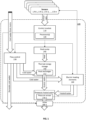
- An exemplary water provision system according to an embodiment is shown in Fig. 1 .
- the water heating system 100 comprises a control module 110.
- the control module 110 is communicatively coupled to, and configured to control, various elements of the water heating system, including a flow control 130 for example in the form of one or more valves arranged to control the flow of water into, out of and around the system, a (ground source or air source) heat pump 140 configured to extract heat from the surroundings and deposit the extracted heat in a thermal energy storage 150 to be used to heat water, and one or more electric heating elements 160 configured to directly heat cold water to a desired temperature by controlling (by the control module 110) the amount of energy supplied to the electric heating elements 160. Heated water, whether heated by the thermal energy storage 150 or heated by the electric heating elements 160, is then directed to one or more water outlets as and when needed.
- a flow control 130 for example in the form of one or more valves arranged to control the flow of water into, out of and around the system
- a (ground source or air source) heat pump 140 configured to extract heat from the surroundings and deposit the extracted heat in a thermal energy storage 150 to
- the heat pump 140 extracts heat from the surroundings into a thermal energy storage medium within the thermal energy storage 150.
- the thermal energy storage medium may optionally also be heated by other sources such as the electric heating elements 160 if desired.
- the heat pump 140 continues to deposit extracted heat to the thermal energy storage medium until it reaches a desired operation temperature, then cold water e.g. from the mains can be heated by the thermal energy storage medium in a heat exchanger 152 to the desired temperature.
- the heated water may then be output for distribution around a water distribution network that comprises e.g. various hot/cold water taps, shower(s), etc.
- the control module 110 comprises one or more processors 120 configured to execute instructions for controlling operations of the water heating system.
- the control module 110 is configured to receive sensor data from a plurality of sensors 170-1, 170-2, 170-3, ..., 170-n.
- the plurality of sensors 170-1, 170-2, 170-3, ..., 170-n may for example include one or more air temperature sensors disposed indoor and/or outdoor, one or more water temperature sensors, one or more water pressure sensors, one or more timers, and may include other sensors not directly linked to the water provision system 100 such as one or more motion sensors, a GPS signal receiver, calendar, weather forecasting app on e.g. a smartphone carried by an occupant and in communication with the control module via a communication channel.
- the one or more processors 120 of the control module 110 is configured, in the present embodiment, to use the received input to perform a variety of control functions, for example controlling the flow of water through the flow control 130 to the thermal energy storage 150 or to the electric heating elements 160 to be heated.
- a pressure sensor 170-1 is disposed at a position in the water heating system 100 to measure the water pressure of heated water output by the water heating system 100, and sensor data indicating the measured water pressure is received by the control module 110 which processes the sensor data and controls operation of the water heating system based on the results.
- a flow control e.g. valve 180-1 is disposed at a position in the water heating system 100 to control the flow of heated water output by the water heating system 100 to the water distribution network.
- the control module 110 is configured to control the operation of the valve 180-1 based on the received sensor data from the pressure sensor 170-1.
- Embodiments of the present technology make use of a heat pump and a thermal energy storage (or heat reservoir) as a source of heat for heating cold water. While a heat pump is generally more energy efficient for heating water compared to an electrical resistance heater, a heat pump requires time to start up as it performs various checks and cycles before reaching a normal operation state, and time to transfer sufficient amount of thermal energy into a thermal energy storage medium before reaching the desired operation temperature. On the other hand, an electrical resistance heater is generally able to provide heat more immediately. Thus, a heat pump can take longer to heat the same amount of water to the same temperature compared to an electrical resistance heater.
- the heat pump 140 may for example use a phase change material (PCM), which changes from a solid to a liquid upon heating, as a thermal energy storage medium. Additional time may therefore be required to for the heat pump to first transferred a sufficient amount of heat to turn the PCM from solid to liquid, if it has been allowed to solidify, before it can further raise the temperature of the liquified thermal storage medium.
- PCM phase change material
- This approach of heating water is slower, it consumes less energy to heat water compared to electric heating elements, so overall, energy is conserved and the cost for providing heated water is reduced.
- a phase change material may be used as a thermal storage medium for the heat pump.
- phase change materials are paraffin waxes which have a solid-liquid phase change at temperatures of interest for domestic hot water supplies and for use in combination with heat pumps.
- paraffin waxes that melt at temperatures in the range 40 to 60 degrees Celsius (°C), and within this range waxes can be found that melt at different temperatures to suit specific applications.
- Typical latent heat capacity is between about 180kJ/kg and 230kJ/kg and a specific heat capacity of perhaps 2.27Jg -1 K -1 in the liquid phase, and 2.1Jg -1 K -1 in the solid phase. It can be seen that very considerable amounts of energy can be stored taking using the latent heat of fusion.
- More energy can also be stored by heating the phase change liquid above its melting point.
- the heat pump may be operated to "charge” the thermal energy storage to a higher-than-normal temperature to "overheat" the thermal energy storage.
- a suitable choice of wax may be one with a melting point at around 48°C, such as n-tricosane C 23 , or paraffin C 20 -C 33 , which requires the heat pump to operate at a temperature of around 51°C, and is capable of heating water to a satisfactory temperature of around 45°C for general domestic hot water, sufficient for e.g. kitchen taps, shower/bathroom taps. Cold water may be added to a flow to reduce water temperature if desired. Consideration is given to the temperature performance of the heat pump. Generally, the maximum difference between the input and output temperature of the fluid heated by the heat pump is preferably kept in the range of 5°C to 7°C, although it can be as high as 10°C.
- salt hydrates are also suitable for latent heat energy storage systems such as the present ones.
- Salt hydrates in this context are mixtures of inorganic salts and water, with the phase change involving the loss of all or much of their water. At the phase transition, the hydrate crystals are divided into anhydrous (or less aqueous) salt and water.
- Advantages of salt hydrates are that they have much higher thermal conductivities than paraffin waxes (between 2 to 5 times higher), and a much smaller volume change with phase transition.
- a suitable salt hydrate for the current application is Na 2 S 2 O 3 ⁇ 5H 2 O, which has a melting point around 48°C to 49°C, and latent heat of 200-220 kJ/kg.
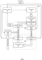
- Fig. 2 shows a central heating branch of the water heating system 100 of Fig. 1 .
- the heating branch is a sealed or closed loop comprising elements of a central heating system 190 which, for example, includes one or more radiating heating elements/modules disposed in multiple locations around the building.
- Water circulating around the heating circuit is heated by heat exchanger 252 in the thermal energy storage 150, which is arranged to store thermal energy (heat) extracted from the surroundings by the heat pump 140 (optionally also received from the electric heating elements 160). Heated water is output from the water heating system 100 via a valve 280-2 (second valve) which controls the flow of the output heated water.
- the heated water circulates the heating circuit and dissipated by the central heating system 290 via one or more radiating heating elements. Cooled water returns from the central heating system 290 around the heating circuit to the water heating system via a valve 280-1 (first valve) which controls the flow of the returned water.
- the pressure of the heating circuit is measured by a first pressure sensor 270-1 and a second pressure sensor 270-2, and sensor data from the first and second pressure sensors 270-1, 270-2 is received by the control module 110, which monitors the water pressure of the heating circuit.
- the first pressure sensor 270-1 is positioned upstream of the first valve 280-1 and downstream of the second valve 280-2, while the second pressure sensor 270-2 is positioned downstream of the first valve 280-1.
- the first and second pressure sensors 270-1, 270-2 and the first and second valves 280-1, 280-2 are positioned such that, when the first and second valves are in a closed position, the heating circuit (or central heating 290) is fluidly isolated from the water heating system, and the first pressure sensor 270-1 is in a position to measure the isolated water pressure in the heating circuit while the second pressure sensor 270-2 is in a position to measure the isolated water pressure in the water heating system.
- the water pressure within the heating circuit is preferably maintained at a level that is within an optimal operating range. If the pressure in the heating circuit falls below the operating range, the heating circuit may first be fluidly isolated by closing the first valve 280-1, and then mains water is released into the return flow by operating a third valve 230 to an open position so as to increase the water pressure in the heating circuit to a level within the optimal range.
- the heating circuit losing pressure.
- a leak somewhere in the heating circuit such as a valve of one of the radiating heating modules, a damaged pipe or joint, or a leak or fault somewhere in the water heating system.
- topping up the heating circuit with mains water to remove the air pocket would resolve the issue.
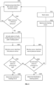
- the water heating system 100 enables such a determination to be made through the use of the first and second pressure sensors 270-1, 270-2 and the first and second valves 280-1, 280-2, as illustrated in Fig. 3 by way of an example.
- the method begins at S301 when the control module receives sensor data from the first pressure sensor 270-1 (first sensor data) and sensor data from the second pressure sensor 270-2 (second sensor data), indicating a water pressure in the heating circuit.
- the predetermined reference water pressure may be any suitable water pressure that represents a lower threshold or minimum water pressure at which the heating circuit branch of the water heating system can operate.
- an optimal operating water pressure e.g. 1.5 bar
- the reference water pressure may be set at the optimal operating water pressure.
- a normal operating pressure range may instead be adopted to account for a normal expected deviation from the optimal operating water pressure, and the reference water pressure may be set at the lower end of the operating pressure range or at the minimum of the operating pressure range.
- the control module at 5304 continues to receive first sensor data from the first pressure sensor 270-1 to monitor the water pressure in the heating circuit (first water pressure) to determine, at S305, whether the first water pressure continues to fall. If the first water pressure continues to fall, this can be used as an indication that the isolated heating circuit is losing water despite water within the heating circuit is not being circulated. Thus, upon determining at S305 that the first water pressure continues to fall (YES branch), the control module determines at 5306 that there is a leak (or fault) in the heating circuit.
- the control module further receives second sensor data from the second pressure sensor 270-2 to monitor the water pressure in the water heating system (second water pressure) at S307, and at S308, determines whether the second water pressure continues to fall. This can be performed simultaneously with, alternately, before, or after S304. If the second water pressure continues to fall, this can be used as an indication that there may be a leak or a fault in the water heating system. Thus, upon determining at S308 that the second water pressure continues to fall (YES branch), the control module determines at S309 that there is a fault or a leak in the water heating system.
- the control module may simultaneously or in turn determine whether the first water pressure or the second water pressure continues to fall (S305, S308), and only when both the first water pressure and the second water pressure are determined to remain substantially constant for a sufficient length of time after operating the first and second valves 280-1, 280-2 to the closed position (NO branch), the control module repressurises the heating circuit at S310 by releasing the second valve 280-2, to allow water to flow from the water heating system to the heating circuit, while maintaining the first valve 280-1 in the closed position to prevent water from returning from the heating circuit to the water heating system, and operating the third valve 230 to introduce mains water into the return route to increase the water pressure in the heating circuit until it reaches a desired pressure, e.g.
- the control module at 5311 closes the third valve 230 to stop the flow of mains water and releases the first valve 280-1 to allow normal operation of the heating circuit to resume.
- the invention it is possible to determine whether there is a leak in the water heating system and/or the heating circuit when the water pressure in the heating circuit falls below the reference water pressure (or a minimum water pressure). Only when it is determined that there is no leak in either the water heating system or the heating circuit would the heating circuit be repressurised. In doing so, it is possible to give an early warning when a leak occurs to prevent a more serious leak caused by late detection and/or pressurising a faulty circuit. Moreover, if there is a leak or fault in the water heating system and the heating circuit is repressurised without the leak or fault being repaired, it can lead to a backflow from the heating circuit into the mains water feeding loop, contaminating water supply with bacteria harmful to health. Through the present invention, it is possible to prevent backflow by only repressurising the heating circuit after it is determined that there is no leak in the water heating system.
- the control module may compare first (second) sensor data received at a first time step, T1, with first (second) sensor data received subsequently at a second time step, T2, after a predetermined time interval from T1, and determine whether the first (second) sensor data received at T2 indicates a lower water pressure than the first (second) sensor data received at T1.
- T1 and T2 may be any suitable and desirable time steps, for example T1 may be the time at which the first (second) water pressure is detected to fall below the reference water pressure, and T2 may be a time after a predetermined interval from T1, e.g. after 10 minutes, 30 minutes, 1 hour, 1 day, etc.
- the control module may generate a warning signal to notify a human operator of the water leakage.
- the warning signal may comprise different form and colour light signal, an audio signal such as a discrete or continuous alarm, a verbal, text or multimedia warning, or a combination thereof.
- the control module may provide on a display an option for a human operator to switch off the water heating system.
- the display may be an integrated display on the control module or an external display (e.g. a smartphone, a tablet, a computer, etc.) in communication, wirelessly or with a wired connection, with the control module.
- the control module may be configured to automatically switch off the water heating system.
- control module may be configured to automatically switch off the water heating system if it is determined that the water leakage is severe, and/or if a human operator has not responded to a recommendation to switch off within a predetermined time, wherein the predetermined time may be dependent on the severity or extent of the leakage.
- the present techniques may take the form of a computer program product embodied in a computer readable medium having computer readable program code embodied thereon.
- the computer readable medium may be a computer readable signal medium or a computer readable storage medium.
- a computer readable medium may be, for example, but is not limited to, an electronic, magnetic, optical, electromagnetic, infrared, or semiconductor system, apparatus, or device, or any suitable combination of the foregoing.
- Computer program code for carrying out operations of the present techniques may be written in any combination of one or more programming languages, including object-oriented programming languages and conventional procedural programming languages.
- program code for carrying out operations of the present techniques may comprise source, object or executable code in a conventional programming language (interpreted or compiled) such as C, or assembly code, code for setting up or controlling an ASIC (Application Specific Integrated Circuit) or FPGA (Field Programmable Gate Array), or code for a hardware description language such as VerilogTM or VHDL (Very high-speed integrated circuit Hardware Description Language).
- a conventional programming language interpreted or compiled
- ASIC Application Specific Integrated Circuit
- FPGA Field Programmable Gate Array
- VerilogTM or VHDL Very high-speed integrated circuit Hardware Description Language
- the program code may execute entirely on the user's computer, partly on the user's computer and partly on a remote computer or entirely on the remote computer or server.
- the remote computer may be connected to the user's computer through any type of network.
- Code components may be embodied as procedures, methods or the like, and may comprise sub-components which may take the form of instructions or sequences of instructions at any of the levels of abstraction, from the direct machine instructions of a native instruction set to high-level compiled or interpreted language constructs.
- a logical method may suitably be embodied in a logic apparatus comprising logic elements to perform the steps of the method, and that such logic elements may comprise components such as logic gates in, for example a programmable logic array or application-specific integrated circuit.
- Such a logic arrangement may further be embodied in enabling elements for temporarily or permanently establishing logic structures in such an array or circuit using, for example, a virtual hardware descriptor language, which may be stored and transmitted using fixed or transmittable carrier media.
- processor any functional block labeled as a "processor”
- functions of the various elements shown in the figures may be provided through the use of dedicated hardware as well as hardware capable of executing software in association with appropriate software.
- the functions may be provided by a single dedicated processor, by a single shared processor, or by a plurality of individual processors, some of which may be shared.
Landscapes
- Engineering & Computer Science (AREA)
- Physics & Mathematics (AREA)
- Thermal Sciences (AREA)
- General Engineering & Computer Science (AREA)
- Mechanical Engineering (AREA)
- Combustion & Propulsion (AREA)
- Chemical & Material Sciences (AREA)
- Life Sciences & Earth Sciences (AREA)
- Sustainable Energy (AREA)
- Sustainable Development (AREA)
- Fluid Mechanics (AREA)
- Environmental Sciences (AREA)
- Atmospheric Sciences (AREA)
- Biodiversity & Conservation Biology (AREA)
- Ecology (AREA)
- Environmental & Geological Engineering (AREA)
- Hydrology & Water Resources (AREA)
- Health & Medical Sciences (AREA)
- Public Health (AREA)
- Water Supply & Treatment (AREA)
- Automation & Control Theory (AREA)
- General Physics & Mathematics (AREA)
- Heat-Pump Type And Storage Water Heaters (AREA)
- Steam Or Hot-Water Central Heating Systems (AREA)
- Heat-Exchange Devices With Radiators And Conduit Assemblies (AREA)
- Domestic Hot-Water Supply Systems And Details Of Heating Systems (AREA)
- Measuring Temperature Or Quantity Of Heat (AREA)
- Investigating Or Analyzing Materials Using Thermal Means (AREA)
- Instantaneous Water Boilers, Portable Hot-Water Supply Apparatuses, And Control Of Portable Hot-Water Supply Apparatuses (AREA)
- Examining Or Testing Airtightness (AREA)
- Percussion Or Vibration Massage (AREA)
- Domestic Plumbing Installations (AREA)
- Sorption Type Refrigeration Machines (AREA)
- Flow Control (AREA)
- Apparatus For Disinfection Or Sterilisation (AREA)
- Other Liquid Machine Or Engine Such As Wave Power Use (AREA)
- Apparatus For Radiation Diagnosis (AREA)
Claims (15)
- Computerimplementiertes Verfahren zur Bestimmung eines Lecks in einem Wasserheizsystem (100), wobei das Wasserheizsystem (100) ein Steuermodul (110) umfasst, das so konfiguriert ist, dass es den Betrieb des Wasserheizsystems (100) steuert, mindestens ein Wasserheizmodul (140, 150), das so konfiguriert ist, dass es Wasser erhitzt, das um einen abgedichteten Heizkreislauf (290) zirkuliert, ein erstes Ventil (280-1), das so konfiguriert ist, dass es den vom Heizkreislauf (290) zum Wasserheizsystem (100) zurückfließenden Wasserstrom steuert, und ein zweites Ventil (280-2), das so konfiguriert ist, dass es den vom Wasserheizsystem (100) zum Heizkreislauf (290) fließenden Wasserstrom steuert, wobei das Verfahren durch das Steuermodul (110) durchgeführt wird und Folgendes umfasst:den Empfang erster Sensordaten von einem ersten Drucksensor (270-1), der stromaufwärts des ersten Ventils (280-1) angeordnet ist;den Empfang zweiter Sensordaten von einem zweiten Drucksensor (270-2), der stromabwärts des ersten Ventils (280-1) angeordnet ist;wenn festgestellt wird, dass die ersten Sensordaten und/oder die zweiten Sensordaten einen Wasserdruck unterhalb eines Referenzwasserdrucks anzeigen, das Schließen des ersten Ventils (280-1) und des zweiten Ventils (280-2), um den Heizkreislauf (290) und den ersten Drucksensor (270-1) von dem Wasserheizsystem (100) und dem zweiten Drucksensor (270-2) zu isolieren;das Überwachen der ersten Sensordaten, die einen Wasserdruck im Heizkreislauf (290) anzeigen, und der zweiten Sensordaten, die einen Wasserdruck im Wasserheizsystem (100) anzeigen; undwenn festgestellt wird, dass die zweiten Sensordaten einen Abfall des Wasserdrucks anzeigen, die Feststellung eines Lecks im Wasserheizsystem (100),dadurch gekennzeichnet, dass das Wasserheizsystem (100) ein drittes Ventil (230) umfasst, das so konfiguriert ist, dass es einen Fluss von Leitungswasser in den Heizkreislauf (290) steuert, und dass das Verfahren ferner umfasst, dass wenn festgestellt wird, dass der durch die ersten Sensordaten angezeigte Wasserdruck und der durch die zweiten Sensordaten angezeigte Wasserdruck im Wesentlichen konstant bleiben, das erste Ventil (280-1) und das dritte Ventil (230) freigegeben werden, um Leitungswasser in den Heizkreislauf (290) zu lassen, um den Wasserdruck auf mindestens den Referenzwasserdruck zu erhöhen.
- Verfahren nach Anspruch 1, das ferner, wenn festgestellt wird, dass die ersten Sensordaten einen Abfall des Wasserdrucks anzeigen, die Feststellung eines Lecks im Heizkreislauf umfasst.
- Verfahren nach Anspruch 1, das ferner, wenn der Wasserdruck im Heizkreislauf mindestens den Referenzwasserdruck erreicht, das Schließen des dritten Ventils, um das Leitungswasser vom Heizkreislauf zu trennen, und das Freigeben des anderen Ventils, des ersten oder des zweiten Ventils umfasst.
- Verfahren nach einem vorhergehenden Anspruch, das ferner die Erzeugung einer Warnung bei Feststellung eines Lecks im Heizkreislauf und/oder im Wasserheizsystem umfasst.
- Verfahren nach einem vorhergehenden Anspruch, wobei die Überwachung der ersten Sensordaten und der zweiten Sensordaten einen oder mehrere der folgenden Schritte umfasst:Vergleichen der ersten Sensordaten, die in einem ersten Zeitschritt T1 empfangen wurden, mit den ersten Sensordaten, die in einem zweiten Zeitschritt T2 nach einem vorbestimmten Zeitintervall empfangen wurden, und Bestimmen, ob die ersten Sensordaten, die in dem zweiten Zeitschritt T2 empfangen wurden, einen niedrigeren Wasserdruck anzeigen als die ersten Sensordaten, die in dem ersten Zeitschritt T1 empfangen wurden; undVergleichen der zweiten Sensordaten, die in einem dritten Zeitschritt T3 empfangen wurden, mit den zweiten Sensordaten, die in einem vierten Zeitschritt T4 nach einem vorbestimmten Zeitintervall empfangen wurden, und Bestimmen, ob die zweiten Sensordaten, die in dem vierten Zeitschritt T4 empfangen wurden, einen niedrigeren Wasserdruck anzeigen als die zweiten Sensordaten, die in dem dritten Zeitschritt T3 empfangen wurden.
- Verfahren nach Anspruch 5, das ferner das Erzeugen einer Warnung umfasst, wenn eine Differenz zwischen einem Wasserdruck, der durch die im ersten Zeitschritt T1 empfangenen ersten Sensordaten angezeigt wird, und einem Wasserdruck, der durch die im zweiten Zeitschritt T2 empfangenen ersten Sensordaten angezeigt wird, eine Druckabfallschwelle überschreitet, und/oder wenn eine Differenz zwischen einem Wasserdruck, der durch die im dritten Zeitschritt T3 empfangenen zweiten Sensordaten angezeigt wird, und einem Wasserdruck, der durch die im vierten Zeitschritt T4 empfangenen zweiten Sensordaten angezeigt wird, eine Druckabfallschwelle überschreitet.
- Verfahren nach Anspruch 4 oder 6, wobei die Warnung ein Lichtsignal, ein Tonsignal, eine verbale, textliche oder multimediale Mitteilung oder eine Kombination davon umfasst.
- Verfahren nach einem vorhergehenden Anspruch, wobei der Referenzwasserdruck einer oder mehreren der folgenden Größen entspricht:einer Abweichung von einem Betriebswasserdruck für den Heizkreislauf; undeinem Mindestbetriebsdruck für den Heizkreislauf.
- Verfahren nach einem vorhergehenden Anspruch, das ferner das Einstellen des Referenzwasserdrucks auf der Grundlage der Betriebsbedingungen des Wasserheizsystems umfasst, wobei die Betriebsbedingungen die Raumlufttemperatur, die Außenlufttemperatur, den atmosphärischen Druck oder eine Kombination davon umfassen.
- Computerlesbares Medium mit maschinenlesbarem Code, der, wenn er von einem Prozessor ausgeführt wird, den Prozessor veranlasst, das Verfahren nach einem vorhergehenden Anspruch durchzuführen.
- Wasserheizsystem (100), das Folgendes umfasst:mindestens ein Wasserheizmodul (140, 150), das so konfiguriert ist, dass es Wasser erwärmt, das in einem abgedichteten Heizkreislauf (290) zirkuliert;ein erstes Ventil (280-1), das so konfiguriert ist, dass es den vom Heizkreislauf (290) zum Wasserheizsystem (100) zurückfließenden Wasserstrom steuert;ein zweites Ventil (280-2), das so konfiguriert ist, dass es den Wasserstrom vom Wasserheizsystem (100) zum Heizkreislauf (290) steuert;einen ersten Drucksensor (270-1), der so konfiguriert ist, dass er einen Wasserdruck im Heizkreislauf (290) misst, der stromaufwärts des ersten Ventils (280-1) angeordnet ist;einen zweiten Drucksensor (270-2), der so konfiguriert ist, dass er einen Wasserdruck im Heizkreislauf (290) misst, der stromabwärts des ersten Ventils (280-1) angeordnet ist; undein Steuermodul (110), das so konfiguriert ist, dass es den Betrieb des Wasserheizsystems (100) steuert, wobei das Steuermodul (110) Folgendes umfasst:mindestens einen Prozessor; undein nichttransitorisches computerlesbares Medium, auf dem Softwarebefehle gespeichert sind, die, wenn sie von dem mindestens einen Prozessor ausgeführt werden, das Steuermodul (110) veranlassen:erste Sensordaten von dem ersten Drucksensor (270-1) zu empfangen;zweite Sensordaten von dem zweiten Drucksensor (270-2) zu empfangen;wenn festgestellt wird, dass die ersten Sensordaten und/oder die zweiten Sensordaten einen Wasserdruck unterhalb eines Referenzwasserdrucks anzeigen, das Schließen des ersten Ventils (280-1) und des zweiten Ventils (280-2), um den Heizkreislauf (290) und den ersten Drucksensor (270-1) von dem Wasserheizsystem (100) und dem zweiten Drucksensor (270-2) zu isolieren;das Überwachen der ersten Sensordaten, die einen Wasserdruck im Heizkreislauf (290) anzeigen, und der zweiten Sensordaten, die einen Wasserdruck im Wasserheizsystem (100) anzeigen; undwenn festgestellt wird, dass die zweiten Sensordaten einen Abfall des Wasserdrucks anzeigen, die Feststellung eines Lecks im Wasserheizsystem (100),dadurch gekennzeichnet, dass das Wasserheizsystem ein drittes Ventil (230) umfasst, das so konfiguriert ist, dass es einen Fluss von Leitungswasser in den Heizkreislauf (290) steuert, wobei die Softwarebefehle ferner das Steuermodul (110) dazu veranlassen, wenn festgestellt wird, dass der durch die ersten Sensordaten angezeigte Wasserdruck und der durch die zweiten Sensordaten angezeigte Wasserdruck im Wesentlichen konstant bleiben, das erste Ventil (280-1) und das dritte Ventil (230) freizugeben, um Leitungswasser in den Heizkreislauf (290) eintreten zu lassen, um den Wasserdruck auf mindestens den Referenzwasserdruck zu erhöhen.
- Wasserheizsystem nach Anspruch 11, wobei die Softwarebefehle ferner das Steuermodul dazu veranlassen, wenn festgestellt, dass die ersten Sensordaten einen Abfall des Wasserdrucks anzeigen, ein Leck im Heizkreislauf festzustellen.
- Wasserheizsystem nach Anspruch 11 oder Anspruch 12, wobei die Softwarebefehle ferner das Steuermodul dazu veranlassen, wenn der Wasserdruck im Heizkreislauf mindestens den Referenzwasserdruck erreicht, das dritte Ventil zu schließen, um das Leitungswasser vom Heizkreislauf zu trennen, und das andere Ventil, das erste oder das zweite Ventil freizugeben.
- Wasserheizsystem nach einem der Ansprüche 11 bis 13, wobei ein oder mehrere Wasserheizmodule eine Wärmepumpe (140) und einen thermischen Energiespeicher (150) umfassen, wobei die Wärmepumpe (140) dazu konfiguriert ist, Wärme aus der Umgebung auf den thermischen Energiespeicher (150) zu übertragen, und wobei der thermische Energiespeicher mindestens einen Wärmetauscher (154) zum Übertragen der gespeicherten thermischen Energie auf Wasser umfasst, das im abgedichteten Heizkreislauf zirkulieren soll.
- Wasserheizsystem nach einem der Ansprüche 11 bis 14, das ferner den Heizkreislauf umfasst, wobei der Heizkreislauf ein oder mehrere Strahlungsheizmodule umfasst, die zum Heizen eines Innenbereichs konfiguriert sind.
Applications Claiming Priority (9)
| Application Number | Priority Date | Filing Date | Title |
|---|---|---|---|
| GBGB2101678.7A GB202101678D0 (en) | 2021-02-07 | 2021-02-07 | Methods and systems and apparatus to support reduced energy and water usage |
| GB2109600.3A GB2603824B (en) | 2021-02-07 | 2021-07-02 | Methods and systems and apparatus to support reduced energy and water usage |
| GB2109599.7A GB2603553B (en) | 2021-02-07 | 2021-07-02 | Energy storage arrangement and installations |
| GB2109596.3A GB2603550B (en) | 2021-02-07 | 2021-07-02 | Energy storage arrangement and installations |
| GB2109593.0A GB2603976B (en) | 2021-02-07 | 2021-07-02 | Methods of configuring and controlling hot water supply installations |
| GB2109598.9A GB2603552B (en) | 2021-02-07 | 2021-07-02 | Energy storage arrangements and installations |
| GB2109597.1A GB2603551B (en) | 2021-02-07 | 2021-07-02 | Energy storage arrangements and installations including such energy storage arrangements |
| GB2109594.8A GB2604668B (en) | 2021-02-07 | 2021-07-02 | Methods and systems and apparatus to support reduced energy and water usage |
| PCT/IB2022/051083 WO2022168051A1 (en) | 2021-02-07 | 2022-02-07 | Method of determining a leak in a water heating system and water heating system |
Publications (3)
| Publication Number | Publication Date |
|---|---|
| EP4288708A1 EP4288708A1 (de) | 2023-12-13 |
| EP4288708C0 EP4288708C0 (de) | 2024-12-25 |
| EP4288708B1 true EP4288708B1 (de) | 2024-12-25 |
Family
ID=74879193
Family Applications (9)
| Application Number | Title | Priority Date | Filing Date |
|---|---|---|---|
| EP22709799.5A Pending EP4288721A1 (de) | 2021-02-07 | 2022-02-07 | Heisswasserversorgung |
| EP22709016.4A Active EP4288731B1 (de) | 2021-02-07 | 2022-02-07 | Anlage, verfahren zur steuerung einer wärmepumpe in einer anlage, prozessor und speicher, sowie computerlesbares speicher medium |
| EP22709022.2A Pending EP4288710A1 (de) | 2021-02-07 | 2022-02-07 | Verfahren zur konfiguration und steuerung von warmwasserversorgungsanlagen |
| EP22709020.6A Pending EP4288734A1 (de) | 2021-02-07 | 2022-02-07 | Energiespeicheranordnung und -anlagen |
| EP22709017.2A Active EP4288732B1 (de) | 2021-02-07 | 2022-02-07 | Energiespeicheranordnung und verfahren zur steuerung einer wärmepumpe |
| EP22707843.3A Active EP4288708B1 (de) | 2021-02-07 | 2022-02-07 | Verfahren zur bestimmung einer leckage in einem wasserheizsystem und wasserheizsystem |
| EP22709021.4A Active EP4288709B1 (de) | 2021-02-07 | 2022-02-07 | Verfahren und systeme und gerät zur unterstützung der reduzierung des energie- und wassersverbrauchs |
| EP22709018.0A Pending EP4288733A1 (de) | 2021-02-07 | 2022-02-07 | Energiespeicheranordnungen und anlagen mit solchen energiespeicheranordnungen |
| EP22709019.8A Active EP4288724B1 (de) | 2021-02-07 | 2022-02-07 | Energiespeicheranordnungen und -anlagen |
Family Applications Before (5)
| Application Number | Title | Priority Date | Filing Date |
|---|---|---|---|
| EP22709799.5A Pending EP4288721A1 (de) | 2021-02-07 | 2022-02-07 | Heisswasserversorgung |
| EP22709016.4A Active EP4288731B1 (de) | 2021-02-07 | 2022-02-07 | Anlage, verfahren zur steuerung einer wärmepumpe in einer anlage, prozessor und speicher, sowie computerlesbares speicher medium |
| EP22709022.2A Pending EP4288710A1 (de) | 2021-02-07 | 2022-02-07 | Verfahren zur konfiguration und steuerung von warmwasserversorgungsanlagen |
| EP22709020.6A Pending EP4288734A1 (de) | 2021-02-07 | 2022-02-07 | Energiespeicheranordnung und -anlagen |
| EP22709017.2A Active EP4288732B1 (de) | 2021-02-07 | 2022-02-07 | Energiespeicheranordnung und verfahren zur steuerung einer wärmepumpe |
Family Applications After (3)
| Application Number | Title | Priority Date | Filing Date |
|---|---|---|---|
| EP22709021.4A Active EP4288709B1 (de) | 2021-02-07 | 2022-02-07 | Verfahren und systeme und gerät zur unterstützung der reduzierung des energie- und wassersverbrauchs |
| EP22709018.0A Pending EP4288733A1 (de) | 2021-02-07 | 2022-02-07 | Energiespeicheranordnungen und anlagen mit solchen energiespeicheranordnungen |
| EP22709019.8A Active EP4288724B1 (de) | 2021-02-07 | 2022-02-07 | Energiespeicheranordnungen und -anlagen |
Country Status (8)
| Country | Link |
|---|---|
| US (5) | US12305930B2 (de) |
| EP (9) | EP4288721A1 (de) |
| JP (2) | JP2024508653A (de) |
| KR (1) | KR102691155B1 (de) |
| CN (2) | CN117063038B (de) |
| AU (2) | AU2022216917A1 (de) |
| ES (5) | ES3040349T3 (de) |
| GB (37) | GB202101678D0 (de) |
Families Citing this family (20)
| Publication number | Priority date | Publication date | Assignee | Title |
|---|---|---|---|---|
| ES3016633T3 (en) | 2021-02-07 | 2025-05-09 | Octopus Energy Heating Ltd | Methods and systems for modulating energy usage |
| GB2612741B (en) * | 2021-02-07 | 2023-11-01 | Octopus Energy Heating Ltd | Methods and systems and apparatus to support reduced energy and water usage |
| JP2024508646A (ja) | 2021-02-07 | 2024-02-28 | オクトパス エナジー ヒーティング リミテッド | ユーティリティ消費を管理するための方法及びシステム |
| JP7544987B2 (ja) | 2021-02-07 | 2024-09-03 | オクトパス エナジー ヒーティング リミテッド | ヒートポンプのデフロストサイクルを実施するための方法およびシステム |
| EP4288704B1 (de) | 2021-02-07 | 2025-01-29 | Octopus Energy Heating Limited | Methoden, systeme und geräte zur unterstützung eines reduzierten energie- und wasserverbrauchs |
| GB202101678D0 (en) | 2021-02-07 | 2021-03-24 | Octopus Energy Ltd | Methods and systems and apparatus to support reduced energy and water usage |
| GB2613709B (en) | 2021-02-07 | 2024-02-28 | Octopus Energy Heating Ltd | Methods and systems and apparatus to support reduced energy and water usage |
| DE102021118417A1 (de) * | 2021-07-16 | 2023-01-19 | Envola GmbH | Energiespeicheraußengerät |
| GB2615544B (en) * | 2022-02-10 | 2024-06-12 | Baker Hughes Energy Technology UK Ltd | Subsea heat bank with PCM heat storing member |
| CN115234973B (zh) * | 2022-07-04 | 2023-09-15 | 国网辽宁省电力有限公司电力科学研究院 | 一种热网动态供热策略确定方法 |
| CN115095998B (zh) * | 2022-07-05 | 2023-11-07 | 珠海格力电器股份有限公司 | 换热系统及其出热水控制方法、热水系统 |
| PT118472B (pt) * | 2023-01-17 | 2024-10-30 | Bosch Termotecnologia Sa | Método para operar um dispositivo de aquecimento de fluidos, dispositivo de aquecimento de fluidos e esquentardor de água instantâneo |
| WO2024165732A1 (en) * | 2023-02-10 | 2024-08-15 | Tepeo Ltd | Determining the state of charge of a thermal storage device |
| CN116577081A (zh) * | 2023-04-28 | 2023-08-11 | 广州市鑫湖能源科技有限公司 | 蓄冷槽测试方法、装置、系统及存储介质 |
| CN116379607B (zh) * | 2023-06-05 | 2023-08-18 | 达州玖源新材料有限公司 | 一种原料加工生产用供热设备及驱控系统 |
| ES2955464A1 (es) * | 2023-09-13 | 2023-12-01 | Gtd Sist De Informacion Sau | Metodo para la planificacion y optimizacion de almacenes termicos en instalaciones industriales de produccion de agua fria y/o caliente |
| WO2025199526A1 (en) * | 2024-03-22 | 2025-09-25 | OhmIQ, Inc. | Heating assembly for quick heating of occupied spaces |
| WO2025202855A1 (en) * | 2024-03-25 | 2025-10-02 | A2A S.P.A. | Heat exchange substation of a district heating system |
| CN119309325B (zh) * | 2024-10-18 | 2025-10-17 | 珠海格力电器股份有限公司 | 双水箱热水系统及其控制方法 |
| CN119171328B (zh) * | 2024-11-01 | 2025-03-11 | 山西乐控电气设备有限公司 | 一种气体绝缘开关柜 |
Family Cites Families (172)
| Publication number | Priority date | Publication date | Assignee | Title |
|---|---|---|---|---|
| FR2281544A1 (fr) * | 1974-08-07 | 1976-03-05 | Zaegel Held Sa | Perfectionnements aux chauffe-eau electriques a accumulation |
| AT356846B (de) * | 1978-07-20 | 1980-05-27 | Holztrattner Heinrich | Geschlossener behaelter zur speicherung und/oder erzeugung von waerme oder kaelte mit eingebauten kammern und rohren |
| FR2431662A1 (fr) * | 1978-07-21 | 1980-02-15 | Bracht Armand | Accumulateur de chaleur |
| CH648412A5 (en) * | 1980-06-09 | 1985-03-15 | Sulzer Ag | Method for measuring and controlling the state of charge of a latent heat store, and device for carrying out the method |
| JPS5795534A (en) * | 1980-12-04 | 1982-06-14 | Matsushita Electric Ind Co Ltd | Heat accumulating apparatus |
| JPS5812992A (ja) * | 1981-07-17 | 1983-01-25 | Hitachi Ltd | 蓄熱装置 |
| FR2519415A1 (fr) * | 1981-12-31 | 1983-07-08 | Electricite De France | Dispositif de commande d'un chauffe-eau a accumulation avec une pompe a chaleur en source principale et une resistance auxiliaire |
| JPS59208300A (ja) * | 1983-05-12 | 1984-11-26 | Mitsubishi Electric Corp | 給水設備の監視装置 |
| JPS61105048A (ja) * | 1984-10-29 | 1986-05-23 | Matsushita Electric Ind Co Ltd | 給湯装置 |
| US4609036A (en) * | 1985-08-07 | 1986-09-02 | The Dow Chemical Company | Bulk heat or cold storage device for thermal energy storage compounds |
| US4718403A (en) * | 1985-10-11 | 1988-01-12 | Exemplar, Inc. | Control for water heater system |
| JP2504437B2 (ja) * | 1987-01-30 | 1996-06-05 | 株式会社東芝 | 空調機 |
| FR2616774B1 (fr) | 1987-06-19 | 1989-10-20 | Air Liquide | Procede de fabrication d'objets en verre comportant une etape de refroidissement |
| JPH0682035B2 (ja) * | 1988-04-02 | 1994-10-19 | 大阪瓦斯株式会社 | 低温液化ガスの蓄熱装置 |
| GB8826885D0 (en) * | 1988-11-17 | 1988-12-21 | Imi Range Ltd | Hot water generating & supply apparatus |
| JPH02197761A (ja) * | 1989-01-25 | 1990-08-06 | Fujitsu General Ltd | ヒートポンプ給湯機 |
| JPH03126109A (ja) * | 1989-10-12 | 1991-05-29 | Yuhshin Co Ltd | 多機能電子水栓 |
| EP0446862A3 (en) | 1990-03-12 | 1994-06-29 | Toto Ltd | Shower apparatus |
| JP2830518B2 (ja) * | 1991-07-18 | 1998-12-02 | 東陶機器株式会社 | 給湯装置 |
| ES2114378B1 (es) * | 1994-05-06 | 1999-01-01 | Univ Catalunya Politecnica | Sistema de suministro automatico de liquido a temperatura regulable, con calentador instantaneo. |
| JPH09178200A (ja) * | 1995-12-21 | 1997-07-11 | Osaka Gas Co Ltd | 温水暖房システムの漏水検出方法及び温水暖房システム |
| JPH1144495A (ja) * | 1997-07-23 | 1999-02-16 | Mitsubishi Chem Eng Corp | 蓄熱装置 |
| JP3895012B2 (ja) * | 1997-07-31 | 2007-03-22 | 株式会社ガスター | 水漏れ検査装置及び検査方法 |
| JP3666266B2 (ja) * | 1998-09-10 | 2005-06-29 | 松下電器産業株式会社 | 給湯システム |
| AT407323B (de) * | 1999-02-16 | 2001-02-26 | Vaillant Gmbh | Elektrodurchlauferhitzer |
| JP2001041570A (ja) * | 1999-08-03 | 2001-02-16 | Matsushita Electric Ind Co Ltd | 給湯機 |
| DE29921889U1 (de) * | 1999-12-13 | 2000-06-21 | GPV management Gesellschaft für Personal, Verwaltung und Betreuung mbH, 04849 Bad Düben | Wärmepumpenheizzentrale |
| JP2001330313A (ja) * | 2000-05-19 | 2001-11-30 | Matsushita Electric Ind Co Ltd | 複合給湯機 |
| DE10151253C1 (de) * | 2001-10-17 | 2002-11-14 | Stiebel Eltron Gmbh & Co Kg | Verfahren zum Betreiben einer Warmwasserversorgungsanlage und Warmwasserversorgungsanlage |
| JP2004101031A (ja) * | 2002-09-06 | 2004-04-02 | Daikin Ind Ltd | 給湯システム |
| JP4016870B2 (ja) * | 2003-04-01 | 2007-12-05 | 松下電器産業株式会社 | ヒートポンプ給湯装置 |
| JP4156437B2 (ja) * | 2003-05-09 | 2008-09-24 | リンナイ株式会社 | 潜熱材の交換時期を報知する蓄熱装置 |
| DE10325929A1 (de) * | 2003-06-07 | 2005-01-05 | Rittal Gmbh & Co. Kg | Kühlanlage für einen oder mehrere Schaltschränke |
| WO2005057086A1 (en) * | 2003-12-12 | 2005-06-23 | Rinnai Corporation | Hot water supply system |
| CN100347488C (zh) | 2004-03-12 | 2007-11-07 | 华南理工大学 | 相变蓄热热泵热水器 |
| US7477950B2 (en) * | 2004-09-28 | 2009-01-13 | Dymocom, Inc. | Method and system for controlling a network of water appliances |
| EP1684035A3 (de) * | 2005-01-24 | 2008-07-16 | Franz Haslinger | Vorrichtungen zur Eisspeicherung und Direktkühlung |
| WO2007059618A1 (en) * | 2005-11-22 | 2007-05-31 | Robert Simoneau | Continuous flow demand controlled microwave water heater |
| AU2007219699C1 (en) * | 2006-02-28 | 2022-09-01 | Rheem Australia Pty Limited | A controllable water heater |
| JP2007278841A (ja) | 2006-04-06 | 2007-10-25 | Nippon Telegr & Teleph Corp <Ntt> | 蓄熱量検出システム |
| AT504285B1 (de) * | 2006-08-16 | 2008-07-15 | Vaillant Austria Gmbh | Verfahren zum betreiben eines durchlauferhitzers mit mehreren zapfstellen |
| US20090173336A1 (en) * | 2006-10-19 | 2009-07-09 | Elcal Research, L.L.C. | Active thermal energy storage system and tank for use therein |
| JP2008121923A (ja) * | 2006-11-09 | 2008-05-29 | Denso Corp | ヒートポンプ式給湯機 |
| JP4787284B2 (ja) * | 2007-03-27 | 2011-10-05 | ダイキン工業株式会社 | ヒートポンプ式給湯装置 |
| JP4767207B2 (ja) * | 2007-03-29 | 2011-09-07 | 三菱電機株式会社 | 給湯装置 |
| JP4999538B2 (ja) * | 2007-05-14 | 2012-08-15 | 株式会社神戸製鋼所 | 蓄熱装置 |
| CN201191144Y (zh) * | 2007-12-03 | 2009-02-04 | 陈定兴 | 相变蓄能换热器 |
| JP2009229007A (ja) * | 2008-03-24 | 2009-10-08 | Panasonic Electric Works Co Ltd | 給湯装置 |
| DE102008017698B3 (de) * | 2008-04-08 | 2010-01-14 | Robert Bosch Gmbh | Wasserwärmungssystem |
| US7724521B2 (en) * | 2008-06-11 | 2010-05-25 | Adc Telecommunications, Inc. | Systems and methods for Venturi fan-assisted cooling |
| CN201265954Y (zh) * | 2008-08-08 | 2009-07-01 | 肖成钢 | 相变蓄热快热型泵热水装置 |
| KR20100030141A (ko) * | 2008-09-09 | 2010-03-18 | 주식회사 네오시스 엔지니어링 | 빙축열 냉방장치용 캡슐 |
| DE102008043030A1 (de) * | 2008-10-22 | 2010-04-29 | BSH Bosch und Siemens Hausgeräte GmbH | Warmwasserspeicher und Verfahren zum Betreiben eines Warmwasserspeichers |
| US8422870B2 (en) * | 2009-02-13 | 2013-04-16 | General Electric Company | Residential heat pump water heater |
| AT508056A1 (de) * | 2009-04-06 | 2010-10-15 | Arnold Hefter | Solaranlage |
| US9442499B2 (en) * | 2009-05-04 | 2016-09-13 | R. W. Beckett Corporation | Controller for temperature regulation system |
| US8457908B2 (en) * | 2009-06-11 | 2013-06-04 | University Of Washington | Sensing events affecting liquid flow in a liquid distribution system |
| CN201443648U (zh) * | 2009-06-17 | 2010-04-28 | 韩盈盈 | 一种节水水龙头 |
| CN201488281U (zh) * | 2009-09-10 | 2010-05-26 | 宁波博浪热能设备有限公司 | 储能式热泵热水器 |
| JP5405964B2 (ja) * | 2009-09-28 | 2014-02-05 | パナソニック株式会社 | ヒートポンプ給湯システム |
| JP2011089692A (ja) * | 2009-10-22 | 2011-05-06 | Panasonic Corp | 給湯機 |
| CN101702492A (zh) * | 2009-11-11 | 2010-05-05 | 大全电气有限公司 | 开关柜风水冷却系统 |
| AU2010100099A4 (en) * | 2010-01-29 | 2010-03-11 | David Michael Brunoli | Temperature activated shower controller |
| GB201005320D0 (en) * | 2010-03-30 | 2010-05-12 | Telepure Ltd | Improvements in controllers, particularly controllers for use in heating, ventilation and air conditioning systems |
| US10168105B2 (en) * | 2010-05-04 | 2019-01-01 | Basf Se | Device and method for storing heat |
| KR20110133073A (ko) * | 2010-06-04 | 2011-12-12 | 최병국 | 히트파이프보일러 및 난방제어 시스템과 순환펌프제어 컨트롤러 |
| JP2012002469A (ja) * | 2010-06-21 | 2012-01-05 | Sanden Corp | 蓄熱装置 |
| JP5435290B2 (ja) * | 2010-06-24 | 2014-03-05 | 株式会社Lixil | 自動水栓装置 |
| US20120060771A1 (en) * | 2010-10-06 | 2012-03-15 | General Electric Company | Hot water heater scheduler |
| US8972073B2 (en) * | 2010-11-10 | 2015-03-03 | Panasonic Corporation | Operation planning method, operation planning device, heat pump hot water supply system operation method, and heat pump hot water supply and heating system operation method |
| KR101168328B1 (ko) | 2010-12-21 | 2012-07-24 | 주식회사 이티나스코 | 열전달효율을 높인 잠열 축열 용기 |
| KR101211816B1 (ko) * | 2010-12-24 | 2012-12-12 | 주식회사 경동나비엔 | 가정용 열병합 발전시스템 |
| GB2488331A (en) * | 2011-02-23 | 2012-08-29 | Star Refrigeration | Heat pump system with a thermal store comprising a phase change material |
| WO2012148551A2 (en) * | 2011-02-24 | 2012-11-01 | Bluelagoon Energy Technologies Ltd. | Methods and apparatus for latent heat (phase change) thermal storage and associated heat transfer and exchange |
| US20120060829A1 (en) * | 2011-03-14 | 2012-03-15 | General Electric Company | Energy management system with solar water heater |
| WO2012153609A1 (ja) * | 2011-05-11 | 2012-11-15 | 株式会社Lixil | 湯水使用管理システム |
| US20120298204A1 (en) * | 2011-05-26 | 2012-11-29 | Erez Roni | Energy saving system and method for heating water |
| JP5714421B2 (ja) * | 2011-06-22 | 2015-05-07 | アイシン精機株式会社 | 瞬間加熱式温水手洗い装置 |
| JP5958912B2 (ja) * | 2011-08-24 | 2016-08-02 | パナソニックIpマネジメント株式会社 | 暖房システムの制御方法及び暖房システム |
| CN102305467A (zh) * | 2011-09-16 | 2012-01-04 | 广东纽恩泰新能源科技发展有限公司 | 蓄热热泵热水器装置 |
| EP2573474B1 (de) * | 2011-09-22 | 2019-05-15 | Panasonic Intellectual Property Management Co., Ltd. | Wärmeverwaltungsalgorithmus für optimierten BHKW-Betrieb |
| JP5549888B2 (ja) * | 2011-11-08 | 2014-07-16 | オリオン機械株式会社 | 温度調整装置 |
| US8611088B2 (en) * | 2011-11-16 | 2013-12-17 | Cooper Technologies Company | Mechanical heat pump for an electrical housing |
| JP5748002B2 (ja) | 2011-12-06 | 2015-07-15 | 三菱電機株式会社 | ヒートポンプ式暖房給湯システム |
| KR20150020171A (ko) * | 2012-05-17 | 2015-02-25 | 찬, 훈 맨 레나 | 정보 제어 시스템 |
| WO2013176169A1 (ja) * | 2012-05-23 | 2013-11-28 | シャープ株式会社 | 保管容器 |
| WO2013175971A1 (ja) * | 2012-05-23 | 2013-11-28 | シャープ株式会社 | 蓄熱部材並びにそれを用いた蓄熱容器及び建材 |
| GB2509354A (en) * | 2012-10-05 | 2014-07-02 | Lobils Ltd | Apparatus to heat domestic hot water and water for a space heating system |
| EP2727646A1 (de) | 2012-11-05 | 2014-05-07 | Flamco B.v. | Kapsel mit Phasenwechselmaterial, Anordnung, Wärmepuffer und Verfahren |
| US9784472B2 (en) * | 2012-11-14 | 2017-10-10 | International Business Machines Corporation | Managing hot water delivery |
| WO2014128929A1 (ja) * | 2013-02-22 | 2014-08-28 | 三菱電機株式会社 | エネルギー管理システム、システムコントローラ、保温制御方法及びプログラム |
| JP6052675B2 (ja) * | 2013-04-25 | 2016-12-27 | パナソニックIpマネジメント株式会社 | ヒートポンプシステム制御装置、ヒートポンプシステム、および、ヒートポンプシステム制御方法 |
| GB2527875A (en) * | 2013-04-30 | 2016-01-06 | Ark Global Technology Ltd | Intelligent electronic water flow regulation system |
| GB2514179A (en) * | 2013-05-17 | 2014-11-19 | Baxi Heating Uk Ltd | Energy store |
| JP6087211B2 (ja) * | 2013-05-27 | 2017-03-01 | リンナイ株式会社 | 暖房システム |
| GB201310821D0 (en) * | 2013-06-18 | 2013-07-31 | Sunamp Ltd | Energy storage system |
| EP3058045B1 (de) | 2013-10-15 | 2019-09-25 | Enrad Ltd. | Elastomer- und/oder verbundstoff für wärmeenergiespeicherung |
| CN203758014U (zh) * | 2013-12-31 | 2014-08-06 | 广东纽恩泰新能源科技发展有限公司 | 热泵热水器 |
| JP6244553B2 (ja) | 2014-03-18 | 2017-12-13 | パナソニックIpマネジメント株式会社 | 蓄熱装置及びそれを備えた温水生成装置 |
| JP6458541B2 (ja) * | 2014-03-25 | 2019-01-30 | 株式会社ノーリツ | 加熱循環回路用熱分配ユニット |
| FR3024214A3 (fr) * | 2014-07-23 | 2016-01-29 | Muller & Cie Soc | Appareil de stockage thermoelectrique saisonnier |
| KR101621168B1 (ko) * | 2014-10-23 | 2016-05-13 | 린나이코리아 주식회사 | 온수공급시스템 |
| JP6115831B2 (ja) * | 2014-11-04 | 2017-04-19 | 三菱電機株式会社 | コントローラ、スケジュール作成方法、及びプログラム |
| US9885498B2 (en) * | 2014-11-13 | 2018-02-06 | Miclau-S.R.L. Inc. | Electrical water heater with a dual resistive heating element and a control method for energy management |
| DE102014225693A1 (de) * | 2014-12-12 | 2016-06-16 | Vaillant Gmbh | Heizsystem mit Warmwasserbereitstellung |
| MX384645B (es) * | 2014-12-17 | 2025-03-14 | Rheem Mfg Co | Calentador de agua eléctrico sin tanque. |
| DE102015203342A1 (de) * | 2015-02-25 | 2016-08-25 | Robert Bosch Gmbh | Steuergerät, Durchlauferhitzer und Verfahren zur Steuerung eines Durchlauferhitzers |
| JP6425803B2 (ja) * | 2015-04-28 | 2018-11-21 | 三菱電機株式会社 | 熱搬送装置監視装置および方法 |
| US20160326732A1 (en) * | 2015-05-05 | 2016-11-10 | James Doyle McCormick | Showerhead Attachment for Controlling the Flow and Temperature of Water |
| WO2016189416A1 (en) * | 2015-05-27 | 2016-12-01 | Stellenbosch University | System and method for determining a customised heating schedule for a water heater |
| CN204902240U (zh) * | 2015-07-31 | 2015-12-23 | 江苏启能新能源材料有限公司 | 一种相变储热式电热水器 |
| CN205037567U (zh) * | 2015-09-30 | 2016-02-17 | 江苏双志新能源有限公司 | 一种自产热互助除霜空气源热泵热水器 |
| JP6539572B2 (ja) * | 2015-11-26 | 2019-07-03 | リンナイ株式会社 | 給湯システム |
| EP3173703A1 (de) * | 2015-11-27 | 2017-05-31 | Sharp Kabushiki Kaisha | Vorwärmung eines wärmespeichers |
| EP3396270A4 (de) * | 2015-12-25 | 2018-12-12 | Mitsubishi Electric Corporation | Steuerungsvorrichtung, steuerungsverfahren für wasserheizer und programm |
| US20170260492A1 (en) * | 2016-03-08 | 2017-09-14 | Tokitae Llc | Temperature stabilized culture incubator |
| US10526771B1 (en) * | 2016-06-17 | 2020-01-07 | Hs Labs, Inc. | Water flow monitoring and leak detection/mitigation system and method |
| FR3053107B1 (fr) | 2016-06-27 | 2018-07-27 | Commissariat A L'energie Atomique Et Aux Energies Alternatives | Systeme de stockage thermique par mcp et comprenant un dispositif de mesure d'un parametre representatif du taux de charge |
| US11002493B2 (en) * | 2016-08-24 | 2021-05-11 | Ford Global Technologies, Llc | Systems and methods for thermal battery control |
| US10983536B2 (en) * | 2016-11-22 | 2021-04-20 | Wint Wi Ltd | User/appliance water signature |
| EP3343203B1 (de) * | 2016-12-28 | 2019-11-13 | Vito NV | Optische verfahren für phasenwechselmaterialien |
| WO2018127550A2 (en) * | 2017-01-06 | 2018-07-12 | Waturu Holding Aps | Use of a sensor signal from a tap |
| JP6449353B2 (ja) * | 2017-01-20 | 2019-01-09 | パーパス株式会社 | 給湯装置、給湯制御方法および給湯システム |
| US10401039B2 (en) * | 2017-02-28 | 2019-09-03 | Ademco Inc. | Evaluation of heating liquid pressure drops in a hydronic heating system |
| IT201700025295U1 (it) * | 2017-03-07 | 2018-09-07 | Fugas S P A | Gruppo satellite idraulico perfezionato |
| CN206609160U (zh) * | 2017-03-07 | 2017-11-03 | 扬州惠通化工科技股份有限公司 | 一种供热稳定的热媒炉系统 |
| JP6879081B2 (ja) * | 2017-06-29 | 2021-06-02 | 株式会社デンソーウェーブ | 漏水検出装置 |
| TWI826384B (zh) * | 2017-07-19 | 2023-12-21 | 美商江森自控科技公司 | 電子器件冷卻系統與採暖、通風、空調以及製冷系統 |
| JP6944832B2 (ja) * | 2017-08-02 | 2021-10-06 | ダイキン工業株式会社 | 給湯システム |
| KR102008943B1 (ko) * | 2017-10-27 | 2019-08-08 | 문병철 | 배전반용 온도제어장치 |
| DE102017220414A1 (de) * | 2017-11-16 | 2019-05-16 | Robert Bosch Gmbh | Verfahren zum Betreiben eines eine Wärmepumpe aufweisenden Wärmespeichersystems |
| CN108050707A (zh) * | 2017-12-12 | 2018-05-18 | 成都前锋电子有限责任公司 | 一种带有清凉浴模式的燃气热水器控制方法及控制装置 |
| KR102431562B1 (ko) * | 2017-12-21 | 2022-08-11 | 주식회사 경동나비엔 | 온수공급장치 및 그 제어방법 |
| JP7013854B2 (ja) * | 2017-12-26 | 2022-02-01 | 株式会社ノーリツ | 貯湯給湯装置 |
| CN109990471A (zh) * | 2018-01-02 | 2019-07-09 | 芜湖美的厨卫电器制造有限公司 | 相变热水器及其控制方法 |
| IT201800002647A1 (it) * | 2018-02-13 | 2019-08-13 | Univ Degli Studi Di Milano Bicocca | Dispositivo e metodo di simulazione di iniezioni di miscele cementizie e/o chimiche in terreni |
| DE102018001313B4 (de) * | 2018-02-20 | 2023-07-20 | Stiebel Eltron Gmbh & Co. Kg | Wasserbereitstellungsvorrichtung zur Bereitstellung von Wasser einstellbarer Temperatur, System zur Wasserbereitstellung sowie Verfahren zum Betreiben einer Wasserbereitstellungsvorrichtung |
| GB201803841D0 (en) * | 2018-03-09 | 2018-04-25 | Sunamp Ltd | Heat pumps |
| IT201800005057A1 (it) | 2018-05-03 | 2019-11-03 | Dispositivo termostatico ed impianto di distribuzione e/o erogazione di acqua sanitaria comprendente tale dispositivo termostatico | |
| EP3809084B1 (de) * | 2018-06-18 | 2024-05-08 | Mitsubishi Electric Corporation | Wärmespeicher, wärmespeichersystem und wärmespeicherverfahren |
| DE102018121053A1 (de) * | 2018-08-29 | 2020-03-05 | Stiebel Eltron Gmbh & Co. Kg | Warmwassersystem, insbesondere Trinkwassererwärmungs- und Trinkwasserleitungsanlagen |
| CN109083232A (zh) * | 2018-09-27 | 2018-12-25 | 贵州大学 | 一种家用智能节水装置 |
| CN109340867B (zh) * | 2018-10-12 | 2021-07-09 | 中国建筑西北设计研究院有限公司 | 一种基于相变蓄热装置的谷电储能系统 |
| DE102018128855A1 (de) * | 2018-11-16 | 2020-05-20 | Viega Technology Gmbh & Co. Kg | Anordnung und Verfahren zum Detektieren von Leckagen in einem Wasserleitungssystem |
| CN111197864A (zh) * | 2018-11-19 | 2020-05-26 | 合肥美的暖通设备有限公司 | 低温型蓄热式的热水器及其蓄热控制方法和用水控制方法 |
| US10852008B2 (en) * | 2018-12-20 | 2020-12-01 | Aerco International, Inc. | Water heater with mix tank fluid time delay for causal feedforward control of hot water temperature |
| GB2580659B (en) * | 2019-01-21 | 2021-11-10 | Canetis Metering Ltd | Heated fluid control system |
| US11421914B2 (en) * | 2019-03-18 | 2022-08-23 | Ut-Battelle, Llc | Thermal storage system with coupled tanks |
| WO2020202487A1 (ja) * | 2019-04-03 | 2020-10-08 | 三菱電機株式会社 | 蓄熱装置 |
| DE102019204957B4 (de) * | 2019-04-08 | 2024-02-01 | Audi Ag | System zum Austauschen elektrischer Energie |
| CN110131889B (zh) * | 2019-05-20 | 2021-11-16 | 合肥美的暖通设备有限公司 | 热泵热水器、控制方法以及计算机可读存储介质 |
| CN111981684B (zh) * | 2019-05-22 | 2022-02-22 | 合肥美的暖通设备有限公司 | 热水器、热水器的控制方法及存储介质 |
| AU2020291441B2 (en) * | 2019-06-14 | 2024-05-09 | Alarm.Com Incorporated | Smart water valve |
| CN210463188U (zh) * | 2019-07-08 | 2020-05-05 | 毛琦 | 一种利用谷电储能的太阳能供暖系统 |
| CN211316300U (zh) * | 2019-11-11 | 2020-08-21 | 大冶海通热工技术有限公司 | 一种利用空气源热泵的固体蓄热供暖装置 |
| US11906174B2 (en) * | 2019-11-26 | 2024-02-20 | Rheem Manufacturing Company | Load based hot water temperature control |
| CN110925943B (zh) * | 2019-11-26 | 2021-02-12 | 珠海格力电器股份有限公司 | 空气源热泵机组的控制方法、装置、设备及存储介质 |
| CN110925856B (zh) * | 2019-11-27 | 2021-02-09 | 珠海格力电器股份有限公司 | 空气源热泵机组控制方法、装置和可读存储介质 |
| CN111076596A (zh) * | 2019-12-30 | 2020-04-28 | 江苏奥斯康新能源有限公司 | 储热型能源箱 |
| FR3106010B1 (fr) * | 2020-01-02 | 2022-07-15 | Delta Dore | Procede et dispositif de determination de profils de consommation d’eau chaude pour des besoins d’hygiene corporelle |
| CN211739265U (zh) * | 2020-01-14 | 2020-10-23 | 东莞理工学院 | 太阳能联合空气源热泵和储能装置的供热系统 |
| CN111237844A (zh) * | 2020-01-19 | 2020-06-05 | 东南大学 | 蓄能与热泵复合的大温差蓄冷蓄热系统 |
| CN111189348A (zh) * | 2020-01-20 | 2020-05-22 | 中国科学院过程工程研究所 | 一种相变储能箱及其使用方法 |
| US11788769B2 (en) * | 2020-04-14 | 2023-10-17 | Rheem Manufacturing Company | On-demand heat pump water heater |
| CN111380258A (zh) * | 2020-04-20 | 2020-07-07 | 佛山市恺庭科技有限公司 | 一种相变储热的空气源热泵供热系统及其逻辑控制方法 |
| CN111649847A (zh) * | 2020-05-28 | 2020-09-11 | 广东万和新电气股份有限公司 | 一种用于淋浴时的报警控制方法及报警系统 |
| CN111750528A (zh) * | 2020-07-08 | 2020-10-09 | 西北工业大学 | 一种无箱式热泵热水装置 |
| CN111811142A (zh) * | 2020-07-28 | 2020-10-23 | 上海海关机电产品检测技术中心 | 一种空气源热泵供热系统 |
| CN112068615B (zh) * | 2020-09-18 | 2021-11-23 | 深圳市丰用实业集团有限公司 | 基于温度及红外传感分析的厨卫智能舒适型洗面盆 |
| US11920871B2 (en) * | 2020-11-25 | 2024-03-05 | Rolls-Royce North American Technologies Inc. | Methods and systems for measuring state of charge of a phase change material thermal battery |
| WO2022168052A1 (en) | 2021-02-07 | 2022-08-11 | Octopus Energy Group Limited | Hot water supply |
| GB202101678D0 (en) | 2021-02-07 | 2021-03-24 | Octopus Energy Ltd | Methods and systems and apparatus to support reduced energy and water usage |
-
2021
- 2021-02-07 GB GBGB2101678.7A patent/GB202101678D0/en not_active Ceased
- 2021-07-02 GB GB2109599.7A patent/GB2603553B/en active Active
- 2021-07-02 GB GB2304349.0A patent/GB2614478B/en active Active
- 2021-07-02 GB GB2109593.0A patent/GB2603976B/en active Active
- 2021-07-02 GB GB2109598.9A patent/GB2603552B/en active Active
- 2021-07-02 GB GB2109600.3A patent/GB2603824B/en active Active
- 2021-07-02 GB GB2215387.8A patent/GB2610942B/en active Active
- 2021-07-02 GB GB2300970.7A patent/GB2612228B/en active Active
- 2021-07-02 GB GB2109594.8A patent/GB2604668B/en active Active
- 2021-07-02 GB GB2109596.3A patent/GB2603550B/en active Active
- 2021-07-02 GB GB2109597.1A patent/GB2603551B/en active Active
- 2021-08-01 GB GB2111079.6A patent/GB2605469B/en active Active
- 2021-08-02 GB GB2111081.2A patent/GB2605660B/en active Active
- 2021-08-02 GB GB2111074.7A patent/GB2604949B/en active Active
- 2021-08-02 GB GB2111078.8A patent/GB2604952B/en active Active
- 2021-08-02 GB GB2111077.0A patent/GB2609902B/en active Active
- 2021-08-02 GB GB2111072.1A patent/GB2604947B/en active Active
- 2021-08-02 GB GB2111082.0A patent/GB2604953B/en active Active
- 2021-08-02 GB GB2111085.3A patent/GB2604669B/en active Active
- 2021-08-02 GB GB2111076.2A patent/GB2604951B/en active Active
- 2021-08-02 GB GB2111070.5A patent/GB2604945B/en active Active
- 2021-08-02 GB GB2111073.9A patent/GB2604948B/en active Active
- 2021-08-02 GB GB2111088.7A patent/GB2609051B/en active Active
- 2021-08-02 GB GB2111075.4A patent/GB2604950B/en active Active
- 2021-08-02 GB GB2111089.5A patent/GB2606037B/en active Active
- 2021-08-02 GB GB2111071.3A patent/GB2604946B/en active Active
- 2021-08-02 GB GB2111080.4A patent/GB2608463B/en active Active
- 2021-08-02 GB GB2111084.6A patent/GB2604955B/en active Active
- 2021-08-02 GB GB2111086.1A patent/GB2604956B/en active Active
- 2021-08-02 GB GB2111069.7A patent/GB2604944B/en active Active
- 2021-08-02 GB GB2111083.8A patent/GB2604954B/en active Active
- 2021-08-02 GB GB2111087.9A patent/GB2605213B/en active Active
-
2022
- 2022-02-07 GB GB2201561.4A patent/GB2603649B/en active Active
- 2022-02-07 EP EP22709799.5A patent/EP4288721A1/de active Pending
- 2022-02-07 EP EP22709016.4A patent/EP4288731B1/de active Active
- 2022-02-07 EP EP22709022.2A patent/EP4288710A1/de active Pending
- 2022-02-07 JP JP2023547349A patent/JP2024508653A/ja active Pending
- 2022-02-07 EP EP22709020.6A patent/EP4288734A1/de active Pending
- 2022-02-07 CN CN202280013799.0A patent/CN117063038B/zh active Active
- 2022-02-07 ES ES22709021T patent/ES3040349T3/es active Active
- 2022-02-07 EP EP22709017.2A patent/EP4288732B1/de active Active
- 2022-02-07 EP EP22707843.3A patent/EP4288708B1/de active Active
- 2022-02-07 JP JP2023547559A patent/JP7564376B2/ja active Active
- 2022-02-07 EP EP22709021.4A patent/EP4288709B1/de active Active
- 2022-02-07 US US18/275,911 patent/US12305930B2/en active Active
- 2022-02-07 AU AU2022216917A patent/AU2022216917A1/en active Pending
- 2022-02-07 ES ES22709017T patent/ES3015721T3/es active Active
- 2022-02-07 ES ES22709019T patent/ES3015759T3/es active Active
- 2022-02-07 US US18/275,917 patent/US12123656B2/en active Active
- 2022-02-07 US US18/264,389 patent/US12276463B2/en active Active
- 2022-02-07 GB GB2201563.0A patent/GB2605004B/en active Active
- 2022-02-07 GB GB2201562.2A patent/GB2603650B/en active Active
- 2022-02-07 EP EP22709018.0A patent/EP4288733A1/de active Pending
- 2022-02-07 KR KR1020237028198A patent/KR102691155B1/ko active Active
- 2022-02-07 ES ES22707843T patent/ES3006998T3/es active Active
- 2022-02-07 CN CN202280023448.8A patent/CN117083499B/zh active Active
- 2022-02-07 AU AU2022216911A patent/AU2022216911B2/en active Active
- 2022-02-07 GB GB2201565.5A patent/GB2603651B/en active Active
- 2022-02-07 US US18/276,006 patent/US20240093882A1/en active Pending
- 2022-02-07 ES ES22709016T patent/ES3015719T3/es active Active
- 2022-02-07 EP EP22709019.8A patent/EP4288724B1/de active Active
- 2022-02-07 GB GB2310761.8A patent/GB2617964B/en active Active
-
2023
- 2023-08-03 US US18/229,969 patent/US12352504B2/en active Active
Also Published As
Similar Documents
| Publication | Publication Date | Title |
|---|---|---|
| EP4288708B1 (de) | Verfahren zur bestimmung einer leckage in einem wasserheizsystem und wasserheizsystem | |
| WO2022168051A1 (en) | Method of determining a leak in a water heating system and water heating system | |
| US11493401B2 (en) | Arrangement and method for detecting leaks in a water pipe system | |
| US4232530A (en) | Heat pump system compressor start fault detector | |
| AU2010214030A1 (en) | Residential heat pump water heater | |
| KR101552495B1 (ko) | 동파 방지 시스템 및 스마트기기를 이용한 동파 방지 시스템의 알람 및 유지보수 장치와 방법 | |
| EP2542872A1 (de) | Verfahren und vorrichtung zur erkennung von leckagen | |
| US10443859B2 (en) | Water heating assembly for providing hot water in a reduced time to a point of use, and related kit, use and method | |
| JP5705332B2 (ja) | 瞬間湯沸器 | |
| US20240280272A1 (en) | Device and methodology for early detection of fluid loss and notification and system shutdown for a closed loop fluid heat transfer system | |
| GB2580289A (en) | Pressure monitoring system for hot water tanks and method of operating same | |
| CN110036158A (zh) | 饮用水节水器 | |
| EP4278135B1 (de) | Verfahren zur prädiktiven wartung von primärkreislaufkomponenten eines kessels | |
| US20160069574A1 (en) | Heat pump water heater appliance and a method for operating a heat pump water heater appliance | |
| KR102216717B1 (ko) | 전기 보일러의 순환이상 제어장치 및 그 제어방법 | |
| KR101555959B1 (ko) | 태양열 집열장치 | |
| JP3584464B2 (ja) | 即時出湯装置及びその運転制御方法 | |
| JP6121864B2 (ja) | 給湯機 | |
| CN103543027B (zh) | 一种节温器工作温度的自动检测系统 | |
| BR112017000588B1 (pt) | Dispositivo para o preenchimento de sistemas de ar condicionado de veículo com agente de refrigeração r744 | |
| JP7393635B2 (ja) | 給湯装置 | |
| JP3465534B2 (ja) | 補助給湯器付給湯装置の補助給湯器側給湯停止判定方法および補助給湯器付給湯装置 | |
| JPH0198932A (ja) | 漏水検出機能付冷暖房用カロリーメータ | |
| JPH07333131A (ja) | プロセス内流体粘度測定方法および装置 | |
| JP6696158B2 (ja) | 温水装置 |
Legal Events
| Date | Code | Title | Description |
|---|---|---|---|
| STAA | Information on the status of an ep patent application or granted ep patent |
Free format text: STATUS: UNKNOWN |
|
| STAA | Information on the status of an ep patent application or granted ep patent |
Free format text: STATUS: THE INTERNATIONAL PUBLICATION HAS BEEN MADE |
|
| PUAI | Public reference made under article 153(3) epc to a published international application that has entered the european phase |
Free format text: ORIGINAL CODE: 0009012 |
|
| STAA | Information on the status of an ep patent application or granted ep patent |
Free format text: STATUS: REQUEST FOR EXAMINATION WAS MADE |
|
| 17P | Request for examination filed |
Effective date: 20230906 |
|
| AK | Designated contracting states |
Kind code of ref document: A1 Designated state(s): AL AT BE BG CH CY CZ DE DK EE ES FI FR GB GR HR HU IE IS IT LI LT LU LV MC MK MT NL NO PL PT RO RS SE SI SK SM TR |
|
| DAV | Request for validation of the european patent (deleted) | ||
| DAX | Request for extension of the european patent (deleted) | ||
| REG | Reference to a national code |
Ref country code: DE Free format text: PREVIOUS MAIN CLASS: F24D0019100000 Ipc: F24D0017020000 Ref country code: DE Ref legal event code: R079 Ref document number: 602022009113 Country of ref document: DE Free format text: PREVIOUS MAIN CLASS: F24D0019100000 Ipc: F24D0017020000 |
|
| GRAP | Despatch of communication of intention to grant a patent |
Free format text: ORIGINAL CODE: EPIDOSNIGR1 |
|
| STAA | Information on the status of an ep patent application or granted ep patent |
Free format text: STATUS: GRANT OF PATENT IS INTENDED |
|
| RIC1 | Information provided on ipc code assigned before grant |
Ipc: F24H 15/31 20220101ALI20240918BHEP Ipc: F24H 15/242 20220101ALI20240918BHEP Ipc: F24H 15/12 20220101ALI20240918BHEP Ipc: F24D 19/10 20060101ALI20240918BHEP Ipc: F24D 17/02 20060101AFI20240918BHEP |
|
| INTG | Intention to grant announced |
Effective date: 20240926 |
|
| GRAS | Grant fee paid |
Free format text: ORIGINAL CODE: EPIDOSNIGR3 |
|
| GRAA | (expected) grant |
Free format text: ORIGINAL CODE: 0009210 |
|
| STAA | Information on the status of an ep patent application or granted ep patent |
Free format text: STATUS: THE PATENT HAS BEEN GRANTED |
|
| AK | Designated contracting states |
Kind code of ref document: B1 Designated state(s): AL AT BE BG CH CY CZ DE DK EE ES FI FR GB GR HR HU IE IS IT LI LT LU LV MC MK MT NL NO PL PT RO RS SE SI SK SM TR |
|
| REG | Reference to a national code |
Ref country code: GB Ref legal event code: FG4D |
|
| REG | Reference to a national code |
Ref country code: CH Ref legal event code: EP |
|
| REG | Reference to a national code |
Ref country code: DE Ref legal event code: R096 Ref document number: 602022009113 Country of ref document: DE |
|
| REG | Reference to a national code |
Ref country code: IE Ref legal event code: FG4D |
|
| U01 | Request for unitary effect filed |
Effective date: 20250115 |
|
| U07 | Unitary effect registered |
Designated state(s): AT BE BG DE DK EE FI FR IT LT LU LV MT NL PT RO SE SI Effective date: 20250122 |
|
| REG | Reference to a national code |
Ref country code: ES Ref legal event code: FG2A Ref document number: 3006998 Country of ref document: ES Kind code of ref document: T3 Effective date: 20250319 |
|
| U20 | Renewal fee for the european patent with unitary effect paid |
Year of fee payment: 4 Effective date: 20250207 |
|
| PG25 | Lapsed in a contracting state [announced via postgrant information from national office to epo] |
Ref country code: HR Free format text: LAPSE BECAUSE OF FAILURE TO SUBMIT A TRANSLATION OF THE DESCRIPTION OR TO PAY THE FEE WITHIN THE PRESCRIBED TIME-LIMIT Effective date: 20241225 |
|
| PGFP | Annual fee paid to national office [announced via postgrant information from national office to epo] |
Ref country code: IE Payment date: 20250226 Year of fee payment: 4 |
|
| PG25 | Lapsed in a contracting state [announced via postgrant information from national office to epo] |
Ref country code: NO Free format text: LAPSE BECAUSE OF FAILURE TO SUBMIT A TRANSLATION OF THE DESCRIPTION OR TO PAY THE FEE WITHIN THE PRESCRIBED TIME-LIMIT Effective date: 20250325 |
|
| PG25 | Lapsed in a contracting state [announced via postgrant information from national office to epo] |
Ref country code: GR Free format text: LAPSE BECAUSE OF FAILURE TO SUBMIT A TRANSLATION OF THE DESCRIPTION OR TO PAY THE FEE WITHIN THE PRESCRIBED TIME-LIMIT Effective date: 20250326 |
|
| PG25 | Lapsed in a contracting state [announced via postgrant information from national office to epo] |
Ref country code: RS Free format text: LAPSE BECAUSE OF FAILURE TO SUBMIT A TRANSLATION OF THE DESCRIPTION OR TO PAY THE FEE WITHIN THE PRESCRIBED TIME-LIMIT Effective date: 20250325 |
|
| PG25 | Lapsed in a contracting state [announced via postgrant information from national office to epo] |
Ref country code: SM Free format text: LAPSE BECAUSE OF FAILURE TO SUBMIT A TRANSLATION OF THE DESCRIPTION OR TO PAY THE FEE WITHIN THE PRESCRIBED TIME-LIMIT Effective date: 20241225 |
|
| PG25 | Lapsed in a contracting state [announced via postgrant information from national office to epo] |
Ref country code: PL Free format text: LAPSE BECAUSE OF FAILURE TO SUBMIT A TRANSLATION OF THE DESCRIPTION OR TO PAY THE FEE WITHIN THE PRESCRIBED TIME-LIMIT Effective date: 20241225 |
|
| PGFP | Annual fee paid to national office [announced via postgrant information from national office to epo] |
Ref country code: ES Payment date: 20250424 Year of fee payment: 4 |
|
| PG25 | Lapsed in a contracting state [announced via postgrant information from national office to epo] |
Ref country code: IS Free format text: LAPSE BECAUSE OF FAILURE TO SUBMIT A TRANSLATION OF THE DESCRIPTION OR TO PAY THE FEE WITHIN THE PRESCRIBED TIME-LIMIT Effective date: 20250425 |
|
| PG25 | Lapsed in a contracting state [announced via postgrant information from national office to epo] |
Ref country code: SK Free format text: LAPSE BECAUSE OF FAILURE TO SUBMIT A TRANSLATION OF THE DESCRIPTION OR TO PAY THE FEE WITHIN THE PRESCRIBED TIME-LIMIT Effective date: 20241225 |
|
| PG25 | Lapsed in a contracting state [announced via postgrant information from national office to epo] |
Ref country code: CZ Free format text: LAPSE BECAUSE OF FAILURE TO SUBMIT A TRANSLATION OF THE DESCRIPTION OR TO PAY THE FEE WITHIN THE PRESCRIBED TIME-LIMIT Effective date: 20241225 |
|
| PG25 | Lapsed in a contracting state [announced via postgrant information from national office to epo] |
Ref country code: MC Free format text: LAPSE BECAUSE OF FAILURE TO SUBMIT A TRANSLATION OF THE DESCRIPTION OR TO PAY THE FEE WITHIN THE PRESCRIBED TIME-LIMIT Effective date: 20241225 |
|
| REG | Reference to a national code |
Ref country code: CH Ref legal event code: PL |
|
| PG25 | Lapsed in a contracting state [announced via postgrant information from national office to epo] |
Ref country code: CH Free format text: LAPSE BECAUSE OF NON-PAYMENT OF DUE FEES Effective date: 20250228 |
|
| PLBE | No opposition filed within time limit |
Free format text: ORIGINAL CODE: 0009261 |
|
| STAA | Information on the status of an ep patent application or granted ep patent |
Free format text: STATUS: NO OPPOSITION FILED WITHIN TIME LIMIT |
|
| 26N | No opposition filed |
Effective date: 20250926 |