EP4151874B1 - Rillenkugellager mit käfig - Google Patents
Rillenkugellager mit käfig Download PDFInfo
- Publication number
- EP4151874B1 EP4151874B1 EP21944421.3A EP21944421A EP4151874B1 EP 4151874 B1 EP4151874 B1 EP 4151874B1 EP 21944421 A EP21944421 A EP 21944421A EP 4151874 B1 EP4151874 B1 EP 4151874B1
- Authority
- EP
- European Patent Office
- Prior art keywords
- cage body
- cage
- groove
- insertion groove
- piece
- Prior art date
- Legal status (The legal status is an assumption and is not a legal conclusion. Google has not performed a legal analysis and makes no representation as to the accuracy of the status listed.)
- Active
Links
Images


Classifications
-
- F—MECHANICAL ENGINEERING; LIGHTING; HEATING; WEAPONS; BLASTING
- F16—ENGINEERING ELEMENTS AND UNITS; GENERAL MEASURES FOR PRODUCING AND MAINTAINING EFFECTIVE FUNCTIONING OF MACHINES OR INSTALLATIONS; THERMAL INSULATION IN GENERAL
- F16C—SHAFTS; FLEXIBLE SHAFTS; ELEMENTS OR CRANKSHAFT MECHANISMS; ROTARY BODIES OTHER THAN GEARING ELEMENTS; BEARINGS
- F16C33/00—Parts of bearings; Special methods for making bearings or parts thereof
- F16C33/30—Parts of ball or roller bearings
- F16C33/38—Ball cages
- F16C33/3837—Massive or moulded cages having cage pockets surrounding the balls, e.g. machined window cages
- F16C33/3862—Massive or moulded cages having cage pockets surrounding the balls, e.g. machined window cages comprising two annular parts joined together
-
- F—MECHANICAL ENGINEERING; LIGHTING; HEATING; WEAPONS; BLASTING
- F16—ENGINEERING ELEMENTS AND UNITS; GENERAL MEASURES FOR PRODUCING AND MAINTAINING EFFECTIVE FUNCTIONING OF MACHINES OR INSTALLATIONS; THERMAL INSULATION IN GENERAL
- F16C—SHAFTS; FLEXIBLE SHAFTS; ELEMENTS OR CRANKSHAFT MECHANISMS; ROTARY BODIES OTHER THAN GEARING ELEMENTS; BEARINGS
- F16C19/00—Bearings with rolling contact, for exclusively rotary movement
- F16C19/02—Bearings with rolling contact, for exclusively rotary movement with bearing balls essentially of the same size in one or more circular rows
- F16C19/04—Bearings with rolling contact, for exclusively rotary movement with bearing balls essentially of the same size in one or more circular rows for radial load mainly
- F16C19/06—Bearings with rolling contact, for exclusively rotary movement with bearing balls essentially of the same size in one or more circular rows for radial load mainly with a single row or balls
-
- F—MECHANICAL ENGINEERING; LIGHTING; HEATING; WEAPONS; BLASTING
- F16—ENGINEERING ELEMENTS AND UNITS; GENERAL MEASURES FOR PRODUCING AND MAINTAINING EFFECTIVE FUNCTIONING OF MACHINES OR INSTALLATIONS; THERMAL INSULATION IN GENERAL
- F16C—SHAFTS; FLEXIBLE SHAFTS; ELEMENTS OR CRANKSHAFT MECHANISMS; ROTARY BODIES OTHER THAN GEARING ELEMENTS; BEARINGS
- F16C19/00—Bearings with rolling contact, for exclusively rotary movement
- F16C19/02—Bearings with rolling contact, for exclusively rotary movement with bearing balls essentially of the same size in one or more circular rows
- F16C19/14—Bearings with rolling contact, for exclusively rotary movement with bearing balls essentially of the same size in one or more circular rows for both radial and axial load
- F16C19/16—Bearings with rolling contact, for exclusively rotary movement with bearing balls essentially of the same size in one or more circular rows for both radial and axial load with a single row of balls
-
- F—MECHANICAL ENGINEERING; LIGHTING; HEATING; WEAPONS; BLASTING
- F16—ENGINEERING ELEMENTS AND UNITS; GENERAL MEASURES FOR PRODUCING AND MAINTAINING EFFECTIVE FUNCTIONING OF MACHINES OR INSTALLATIONS; THERMAL INSULATION IN GENERAL
- F16C—SHAFTS; FLEXIBLE SHAFTS; ELEMENTS OR CRANKSHAFT MECHANISMS; ROTARY BODIES OTHER THAN GEARING ELEMENTS; BEARINGS
- F16C33/00—Parts of bearings; Special methods for making bearings or parts thereof
- F16C33/30—Parts of ball or roller bearings
- F16C33/38—Ball cages
- F16C33/3837—Massive or moulded cages having cage pockets surrounding the balls, e.g. machined window cages
- F16C33/3862—Massive or moulded cages having cage pockets surrounding the balls, e.g. machined window cages comprising two annular parts joined together
- F16C33/3875—Massive or moulded cages having cage pockets surrounding the balls, e.g. machined window cages comprising two annular parts joined together made from plastic, e.g. two injection moulded parts joined by a snap fit
-
- F—MECHANICAL ENGINEERING; LIGHTING; HEATING; WEAPONS; BLASTING
- F16—ENGINEERING ELEMENTS AND UNITS; GENERAL MEASURES FOR PRODUCING AND MAINTAINING EFFECTIVE FUNCTIONING OF MACHINES OR INSTALLATIONS; THERMAL INSULATION IN GENERAL
- F16C—SHAFTS; FLEXIBLE SHAFTS; ELEMENTS OR CRANKSHAFT MECHANISMS; ROTARY BODIES OTHER THAN GEARING ELEMENTS; BEARINGS
- F16C33/00—Parts of bearings; Special methods for making bearings or parts thereof
- F16C33/30—Parts of ball or roller bearings
- F16C33/38—Ball cages
- F16C33/44—Selection of substances
-
- F—MECHANICAL ENGINEERING; LIGHTING; HEATING; WEAPONS; BLASTING
- F16—ENGINEERING ELEMENTS AND UNITS; GENERAL MEASURES FOR PRODUCING AND MAINTAINING EFFECTIVE FUNCTIONING OF MACHINES OR INSTALLATIONS; THERMAL INSULATION IN GENERAL
- F16C—SHAFTS; FLEXIBLE SHAFTS; ELEMENTS OR CRANKSHAFT MECHANISMS; ROTARY BODIES OTHER THAN GEARING ELEMENTS; BEARINGS
- F16C33/00—Parts of bearings; Special methods for making bearings or parts thereof
- F16C33/30—Parts of ball or roller bearings
- F16C33/58—Raceways; Race rings
- F16C33/583—Details of specific parts of races
-
- F—MECHANICAL ENGINEERING; LIGHTING; HEATING; WEAPONS; BLASTING
- F16—ENGINEERING ELEMENTS AND UNITS; GENERAL MEASURES FOR PRODUCING AND MAINTAINING EFFECTIVE FUNCTIONING OF MACHINES OR INSTALLATIONS; THERMAL INSULATION IN GENERAL
- F16C—SHAFTS; FLEXIBLE SHAFTS; ELEMENTS OR CRANKSHAFT MECHANISMS; ROTARY BODIES OTHER THAN GEARING ELEMENTS; BEARINGS
- F16C33/00—Parts of bearings; Special methods for making bearings or parts thereof
- F16C33/30—Parts of ball or roller bearings
- F16C33/66—Special parts or details in view of lubrication
- F16C33/6637—Special parts or details in view of lubrication with liquid lubricant
- F16C33/664—Retaining the liquid in or near the bearing
- F16C33/6648—Retaining the liquid in or near the bearing in a porous or resinous body, e.g. a cage impregnated with the liquid
-
- F—MECHANICAL ENGINEERING; LIGHTING; HEATING; WEAPONS; BLASTING
- F16—ENGINEERING ELEMENTS AND UNITS; GENERAL MEASURES FOR PRODUCING AND MAINTAINING EFFECTIVE FUNCTIONING OF MACHINES OR INSTALLATIONS; THERMAL INSULATION IN GENERAL
- F16C—SHAFTS; FLEXIBLE SHAFTS; ELEMENTS OR CRANKSHAFT MECHANISMS; ROTARY BODIES OTHER THAN GEARING ELEMENTS; BEARINGS
- F16C33/00—Parts of bearings; Special methods for making bearings or parts thereof
- F16C33/30—Parts of ball or roller bearings
- F16C33/66—Special parts or details in view of lubrication
- F16C33/6637—Special parts or details in view of lubrication with liquid lubricant
- F16C33/664—Retaining the liquid in or near the bearing
- F16C33/6651—Retaining the liquid in or near the bearing in recesses or cavities provided in retainers, races or rolling elements
-
- F—MECHANICAL ENGINEERING; LIGHTING; HEATING; WEAPONS; BLASTING
- F16—ENGINEERING ELEMENTS AND UNITS; GENERAL MEASURES FOR PRODUCING AND MAINTAINING EFFECTIVE FUNCTIONING OF MACHINES OR INSTALLATIONS; THERMAL INSULATION IN GENERAL
- F16C—SHAFTS; FLEXIBLE SHAFTS; ELEMENTS OR CRANKSHAFT MECHANISMS; ROTARY BODIES OTHER THAN GEARING ELEMENTS; BEARINGS
- F16C33/00—Parts of bearings; Special methods for making bearings or parts thereof
- F16C33/72—Sealings
- F16C33/76—Sealings of ball or roller bearings
- F16C33/78—Sealings of ball or roller bearings with a diaphragm, disc, or ring, with or without resilient members
- F16C33/7803—Sealings of ball or roller bearings with a diaphragm, disc, or ring, with or without resilient members suited for particular types of rolling bearings
- F16C33/7806—Sealings of ball or roller bearings with a diaphragm, disc, or ring, with or without resilient members suited for particular types of rolling bearings for spherical roller bearings
-
- F—MECHANICAL ENGINEERING; LIGHTING; HEATING; WEAPONS; BLASTING
- F16—ENGINEERING ELEMENTS AND UNITS; GENERAL MEASURES FOR PRODUCING AND MAINTAINING EFFECTIVE FUNCTIONING OF MACHINES OR INSTALLATIONS; THERMAL INSULATION IN GENERAL
- F16C—SHAFTS; FLEXIBLE SHAFTS; ELEMENTS OR CRANKSHAFT MECHANISMS; ROTARY BODIES OTHER THAN GEARING ELEMENTS; BEARINGS
- F16C33/00—Parts of bearings; Special methods for making bearings or parts thereof
- F16C33/72—Sealings
- F16C33/76—Sealings of ball or roller bearings
- F16C33/78—Sealings of ball or roller bearings with a diaphragm, disc, or ring, with or without resilient members
- F16C33/7816—Details of the sealing or parts thereof, e.g. geometry, material
- F16C33/783—Details of the sealing or parts thereof, e.g. geometry, material of the mounting region
-
- F—MECHANICAL ENGINEERING; LIGHTING; HEATING; WEAPONS; BLASTING
- F16—ENGINEERING ELEMENTS AND UNITS; GENERAL MEASURES FOR PRODUCING AND MAINTAINING EFFECTIVE FUNCTIONING OF MACHINES OR INSTALLATIONS; THERMAL INSULATION IN GENERAL
- F16C—SHAFTS; FLEXIBLE SHAFTS; ELEMENTS OR CRANKSHAFT MECHANISMS; ROTARY BODIES OTHER THAN GEARING ELEMENTS; BEARINGS
- F16C37/00—Cooling of bearings
- F16C37/007—Cooling of bearings of rolling bearings
-
- F—MECHANICAL ENGINEERING; LIGHTING; HEATING; WEAPONS; BLASTING
- F16—ENGINEERING ELEMENTS AND UNITS; GENERAL MEASURES FOR PRODUCING AND MAINTAINING EFFECTIVE FUNCTIONING OF MACHINES OR INSTALLATIONS; THERMAL INSULATION IN GENERAL
- F16C—SHAFTS; FLEXIBLE SHAFTS; ELEMENTS OR CRANKSHAFT MECHANISMS; ROTARY BODIES OTHER THAN GEARING ELEMENTS; BEARINGS
- F16C2208/00—Plastics; Synthetic resins, e.g. rubbers
- F16C2208/02—Plastics; Synthetic resins, e.g. rubbers comprising fillers, fibres
- F16C2208/04—Glass fibres
-
- F—MECHANICAL ENGINEERING; LIGHTING; HEATING; WEAPONS; BLASTING
- F16—ENGINEERING ELEMENTS AND UNITS; GENERAL MEASURES FOR PRODUCING AND MAINTAINING EFFECTIVE FUNCTIONING OF MACHINES OR INSTALLATIONS; THERMAL INSULATION IN GENERAL
- F16C—SHAFTS; FLEXIBLE SHAFTS; ELEMENTS OR CRANKSHAFT MECHANISMS; ROTARY BODIES OTHER THAN GEARING ELEMENTS; BEARINGS
- F16C2208/00—Plastics; Synthetic resins, e.g. rubbers
- F16C2208/20—Thermoplastic resins
- F16C2208/36—Polyarylene ether ketones [PAEK], e.g. PEK, PEEK
-
- F—MECHANICAL ENGINEERING; LIGHTING; HEATING; WEAPONS; BLASTING
- F16—ENGINEERING ELEMENTS AND UNITS; GENERAL MEASURES FOR PRODUCING AND MAINTAINING EFFECTIVE FUNCTIONING OF MACHINES OR INSTALLATIONS; THERMAL INSULATION IN GENERAL
- F16C—SHAFTS; FLEXIBLE SHAFTS; ELEMENTS OR CRANKSHAFT MECHANISMS; ROTARY BODIES OTHER THAN GEARING ELEMENTS; BEARINGS
- F16C2208/00—Plastics; Synthetic resins, e.g. rubbers
- F16C2208/20—Thermoplastic resins
- F16C2208/60—Polyamides [PA]
- F16C2208/62—Polyamides [PA] high performance polyamides, e.g. PA12, PA46
-
- F—MECHANICAL ENGINEERING; LIGHTING; HEATING; WEAPONS; BLASTING
- F16—ENGINEERING ELEMENTS AND UNITS; GENERAL MEASURES FOR PRODUCING AND MAINTAINING EFFECTIVE FUNCTIONING OF MACHINES OR INSTALLATIONS; THERMAL INSULATION IN GENERAL
- F16C—SHAFTS; FLEXIBLE SHAFTS; ELEMENTS OR CRANKSHAFT MECHANISMS; ROTARY BODIES OTHER THAN GEARING ELEMENTS; BEARINGS
- F16C2220/00—Shaping
- F16C2220/02—Shaping by casting
- F16C2220/04—Shaping by casting by injection-moulding
-
- F—MECHANICAL ENGINEERING; LIGHTING; HEATING; WEAPONS; BLASTING
- F16—ENGINEERING ELEMENTS AND UNITS; GENERAL MEASURES FOR PRODUCING AND MAINTAINING EFFECTIVE FUNCTIONING OF MACHINES OR INSTALLATIONS; THERMAL INSULATION IN GENERAL
- F16C—SHAFTS; FLEXIBLE SHAFTS; ELEMENTS OR CRANKSHAFT MECHANISMS; ROTARY BODIES OTHER THAN GEARING ELEMENTS; BEARINGS
- F16C2226/00—Joining parts; Fastening; Assembling or mounting parts
- F16C2226/50—Positive connections
- F16C2226/70—Positive connections with complementary interlocking parts
- F16C2226/74—Positive connections with complementary interlocking parts with snap-fit, e.g. by clips
-
- F—MECHANICAL ENGINEERING; LIGHTING; HEATING; WEAPONS; BLASTING
- F16—ENGINEERING ELEMENTS AND UNITS; GENERAL MEASURES FOR PRODUCING AND MAINTAINING EFFECTIVE FUNCTIONING OF MACHINES OR INSTALLATIONS; THERMAL INSULATION IN GENERAL
- F16C—SHAFTS; FLEXIBLE SHAFTS; ELEMENTS OR CRANKSHAFT MECHANISMS; ROTARY BODIES OTHER THAN GEARING ELEMENTS; BEARINGS
- F16C2226/00—Joining parts; Fastening; Assembling or mounting parts
- F16C2226/50—Positive connections
- F16C2226/70—Positive connections with complementary interlocking parts
- F16C2226/76—Positive connections with complementary interlocking parts with tongue and groove or key and slot
-
- F—MECHANICAL ENGINEERING; LIGHTING; HEATING; WEAPONS; BLASTING
- F16—ENGINEERING ELEMENTS AND UNITS; GENERAL MEASURES FOR PRODUCING AND MAINTAINING EFFECTIVE FUNCTIONING OF MACHINES OR INSTALLATIONS; THERMAL INSULATION IN GENERAL
- F16C—SHAFTS; FLEXIBLE SHAFTS; ELEMENTS OR CRANKSHAFT MECHANISMS; ROTARY BODIES OTHER THAN GEARING ELEMENTS; BEARINGS
- F16C2380/00—Electrical apparatus
- F16C2380/26—Dynamo-electric machines or combinations therewith, e.g. electro-motors and generators
-
- Y—GENERAL TAGGING OF NEW TECHNOLOGICAL DEVELOPMENTS; GENERAL TAGGING OF CROSS-SECTIONAL TECHNOLOGIES SPANNING OVER SEVERAL SECTIONS OF THE IPC; TECHNICAL SUBJECTS COVERED BY FORMER USPC CROSS-REFERENCE ART COLLECTIONS [XRACs] AND DIGESTS
- Y02—TECHNOLOGIES OR APPLICATIONS FOR MITIGATION OR ADAPTATION AGAINST CLIMATE CHANGE
- Y02T—CLIMATE CHANGE MITIGATION TECHNOLOGIES RELATED TO TRANSPORTATION
- Y02T10/00—Road transport of goods or passengers
- Y02T10/80—Technologies aiming to reduce greenhouse gasses emissions common to all road transportation technologies
- Y02T10/86—Optimisation of rolling resistance, e.g. weight reduction
Definitions
- the present disclosure relates to the technical field of bearings and, in particular, to a deep groove ball bearing with a cage.
- drive motors have become key components of new energy vehicles and have the advantages of increased instantaneous power; strong overload capacity; wide speed range; the capability of being frequently started, stopped, accelerated, and decelerated; high torque in low-speed climbing; and low torque in high-speed driving over common motors. It is precisely because of these characteristics of the driving motors that the performance requirement of bearings in the driving motors is higher than that of the general bearing. Bearings in the drive motors are required to have high-speed performance, rapid speed change, low torque, low noise, low-temperature rise, long service life, and the like. To enable the rapid acceleration of the new energy vehicles, a deep groove ball bearing having a high rotational speed is typically provided in the drive motors.
- a cage is provided in the deep groove ball bearing, and the cage is assembled between an inner raceway and an outer raceway.
- the cage includes an annular main body and ball pockets uniformly distributed along the circumference of the annular main body.
- the ball pockets each have a concave spherical surface, which is similar to that of a rolling element of a ball bearing and has a slightly larger radius of curvature.
- An opening is separately formed in the inner diameter surface and the outer diameter surface of the main body of the cage.
- JP 2020 133663 A discloses a split deep groove ball bearing cage with an improved snap fit connection and integrated lubrication arrangement.
- the present disclosure provides a deep groove ball bearing with a cage, which provides a simple structure, easy installation into the overall structure, higher stability, a better use effect of the overall structure, and higher production efficiency.
- the present disclosure provides a deep groove ball bearing with a cage, including an outer ring, an inner ring, the cage, and steel balls.
- the cage is provided between the outer ring and the inner ring. Pockets are formed in the cage, and the steel balls are placed in the pockets.
- the cage is split into an upper cage body and a lower cage body. Pocket grooves are formed alternately in each of the upper cage body and the lower cage body. Pocket grooves in the upper cage body and the lower cage body are combined correspondingly to form the pockets.
- a connecting portion is provided between adjacent pocket grooves in the upper cage body.
- a positioning portion is provided between adjacent pocket grooves in the lower cage body.
- An insertion piece and an insertion groove are provided between the connecting portion and the positioning portion, and the insertion piece and the insertion groove are configured to be fixed with each other to form a fixed connection between the upper cage body and the lower cage body.
- the insertion groove is formed in the positioning portion of the lower cage body, a bump is provided in the insertion groove, the insertion piece is provided on the connecting portion of the upper cage body, a clamping member is provided on an end portion of the insertion piece, and the clamping member is clamped between the bump and a bottom of the insertion groove;
- the bump is arranged adjacent to an inserting port of the insertion groove, and a contact surface of the bump and the clamping member is an arc surface;
- a positioning piece is respectively provided at two sides of the insertion piece, the positioning piece is elastic, and an accommodating groove is formed in a position of the insertion groove corresponding to the positioning piece; the insertion groove communicates with the pocket groove through the accommodating groove, and an oil storage cotton is provided in the accommodating groove.
- the cage can be split into the upper cage body and the lower cage body.
- the steel balls can be installed and placed conveniently through the upper cage body and the lower cage body, and the two cage bodies are connected by a connection piece, which achieves a convenient and efficient connection and a simple structure.
- the cage bodies are made of an injection molding material, which is usually glass fiber reinforced polyamide 66 (PA66), glass fiber reinforced PA46, and glass fiber reinforced polyetheretherketone (PEEK), thereby ensuring the strength of the cage, yielding a lightweight cage body, maintaining a stability of the bearing, and achieving the better use effect.
- PA66 glass fiber reinforced polyamide 66
- PA46 glass fiber reinforced PA46
- PEEK glass fiber reinforced polyetheretherketone
- the insertion groove is formed in the positioning portion of the lower cage body, the bump is provided in the insertion groove, the insertion piece is provided on the connecting portion of the upper cage body, the clamping member is provided on the end portion of the insertion piece, and the clamping member is clamped between the bump and the bottom of the insertion groove.
- the arrangement has the following beneficial effects:
- the insertion piece and the insertion groove are cooperatively inserted, and the clamping member on the insertion piece abuts against the bump, which prevents the upper cage body and the lower cage body from loosening, and achieves the simple structure, and the convenient and efficient connection.
- the bump is arranged adjacent to the inserting port of the insertion groove, and the contact surface of the bump and the clamping member is the arc surface.
- the arrangement has the following beneficial effects:
- the clamping member is clamped more smoothly, which makes installation and production smoother and improves production efficiency.
- the positioning piece is respectively provided at the two sides of the insertion piece, the positioning piece is elastic, and the accommodating groove is formed in the position of the insertion groove corresponding to the positioning piece.
- the arrangement has the following beneficial effects:
- the two cage bodies are connected more firmly and are not loosened easily.
- the positioning piece can provide a counterforce to prevent the separation, thereby improving the stability of the overall structure.
- the insertion groove communicates with the pocket groove through the accommodating groove, and the oil storage cotton is provided in the accommodating groove.
- the arrangement has the following beneficial effects:
- the insertion groove communicates with the pocket groove, and the oil storage cotton is provided in the accommodating groove.
- the positioning piece at each of two sides of the insertion piece is clamped into the accommodating groove and abuts against the oil storage cotton. Consequently, the oil storage cotton abuts against the steel ball, and a lubricant in the oil storage cotton can be coated on the steel ball, thereby lubricating and cooling the steel ball to effectively prolong the service life of the overall structure.
- a first connecting step is provided on the inner wall of the outer ring
- a second connecting step is provided on the outer wall of the inner ring
- a dust cover is clamped between the first connecting step and the second connecting step.
- the arrangement has the following beneficial effects:
- the steel balls are shielded to achieve a better use effect of the overall structure.
- the structure is simple for implementation.
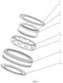
- a deep groove ball bearing with a cage includes outer ring 2, inner ring 1, a cage, and steel balls.
- the cage is provided between the outer ring 2 and the inner ring 1. Pockets are formed in the cage. The steel balls are placed in the pockets.
- the cage is split into upper cage body 4 and lower cage body 3. Pocket grooves 41 are formed alternately in each of the upper cage body 4 and the lower cage body 3. Pocket grooves 41 in the upper cage body 4 and the lower cage body 3 are combined correspondingly to form the pockets.
- Connecting portion 42 is provided between adjacent pocket grooves 41 in the upper cage body 4.
- Positioning portion 31 is provided between adjacent pocket grooves 41 in the lower cage body 3.
- Insertion piece 43 and insertion groove 32 are provided between the connecting portion 42 and the positioning portion 31.
- the insertion piece 43 and the insertion groove 32 are configured to be fixed with each other to form a fixed connection between the upper cage body 4 and the lower cage body 3.
- the insertion groove 32 is formed in the positioning portion 31 of the lower cage body 3.
- Bump 33 is provided in the insertion groove 32.
- the insertion piece 43 is provided on the connecting portion 42 of the upper cage body 4.
- Clamping member 44 is provided on an end portion of the insertion piece 43.
- the clamping member 44 is clamped between the bump 33 and the bottom of the insertion groove 32.
- the bump 33 is arranged adjacent to an inserting port of the insertion groove 32.
- a contact surface of the bump 33 and the clamping member 44 is an arc surface.
- Positioning piece 45 is respectively provided at two sides of the insertion piece 43.
- the positioning piece 45 is elastic.
- Accommodating groove 34 is formed in a position of the insertion groove 32 corresponding to the positioning piece 45.
- the insertion groove 32 communicates with the pocket groove 41 through the accommodating groove 34.
- An oil storage cotton is provided in the accommodating groove 34.
- a first connecting step is provided on the inner wall of the outer ring 2.
- Second connecting step 11 is provided on the outer wall of the inner ring 1. Dust cover 5 is clamped between the first connecting step and the second connecting step 11.
- a deep groove ball bearing with a cage includes outer ring 2, inner ring 1, a cage, and steel balls.
- the cage is provided between the outer ring 2 and the inner ring 1. Pockets are formed in the cage. The steel balls are placed in the pockets.
- the cage is split into upper cage body 4 and lower cage body 3. Pocket grooves 41 are formed alternately in each of the upper cage body 4 and the lower cage body 3. Pocket grooves 41 in the upper cage body 4 and the lower cage body 3 are combined correspondingly to form the pockets.
- Connecting portion 42 is provided between adjacent pocket grooves 41 in the upper cage body 4.
- Positioning portion 31 is provided between adjacent pocket grooves 41 in the lower cage body 3.
- Insertion piece 43 and insertion groove 32 are provided between the connecting portion 42 and the positioning portion 31.
- the insertion piece 43 and the insertion groove 32 are configured to be fixed with each other to form a fixed connection between the upper cage body 4 and the lower cage body 3.
- the insertion groove 32 is formed in the positioning portion 31 of the lower cage body 3.
- the insertion piece 43 is provided on the connecting portion 42 of the upper cage body 4.
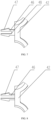
- the insertion piece 43 is provided as two connecting arms 46.
- the connecting arm 46 includes one end connected to the connecting portion 42 and the other end provided with hook 47.
- the connecting arm 46 passes through the insertion groove 32, and the hook 47 is hooked on the outer wall of the positioning portion 31.
- the hook 47 is provided in a wedge shape.
- a contact surface of the hook 47 and the insertion groove 32 is an inclined surface.
- Connecting bridge 48 is provided between the two connecting arms 46.
- the connecting portion 42 on the upper cage body 4 is lower than the bottom of the pocket groove 41.
- the length of the hook 47 is less than the distance between the connecting portion 42 and the bottom of the pocket groove 41.
- a first connecting step is provided on the inner wall of the outer ring 2.
- Second connecting step 11 is provided on the outer wall of the inner ring 1. Dust cover 5 is clamped between the first connecting step and the second connecting step 11. (Not constituting a part of the invention)
- a deep groove ball bearing with a cage includes outer ring 2, inner ring 1, a cage, and steel balls.
- the cage is provided between the outer ring 2 and the inner ring 1. Pockets are formed in the cage. The steel balls are placed in the pockets.
- the cage is split into upper cage body 4 and lower cage body 3. Pocket grooves 41 are formed alternately in each of the upper cage body 4 and the lower cage body 3. Pocket grooves 41 in the upper cage body 4 and the lower cage body 3 are combined correspondingly to form the pockets.
- Connecting portion 42 is provided between adjacent pocket grooves 41 in the upper cage body 4.
- Positioning portion 31 is provided between adjacent pocket grooves 41 in the lower cage body 3.
- Insertion piece 43 and insertion groove 32 are provided between the connecting portion 42 and the positioning portion 31.
- the insertion piece 43 and the insertion groove 32 are configured to be fixed with each other to form a fixed connection between the upper cage body 4 and the lower cage body 3.
- the insertion groove 32 is formed in the positioning portion 31 of the lower cage body 3.
- the insertion piece 43 is provided on the connecting portion 42 of the upper cage body 4.
- the insertion piece 43 is provided as two connecting arms 46.
- the connecting arm 46 includes one end connected to the connecting portion 42 and the other end provided with hook 47.
- the connecting arm 46 passes through the insertion groove 32, and the hook 47 is hooked on the outer wall of the positioning portion 31.
- the hook 47 is provided in a wedge shape.
- a contact surface of the hook 47 and the insertion groove 32 is an inclined surface.
- Connecting bridge 48 is provided between the two connecting arms 46.
- the connecting portion 42 on the upper cage body 4 is lower than the bottom of the pocket groove 41.
- the length of hook 47 is less than the distance between the connecting portion 42 and the bottom of the pocket groove 41.
- a deep groove ball bearing with a cage includes outer ring 2, inner ring 1, a cage, and steel balls.
- the cage is provided between the outer ring 2 and the inner ring 1. Pockets are formed in the cage. The steel balls are placed in the pockets.
- the cage is split into upper cage body 4 and lower cage body 3. Pocket grooves 41 are formed alternately in each of the upper cage body 4 and the lower cage body 3. Pocket grooves 41 in the upper cage body 4 and the lower cage body 3 are combined correspondingly to form the pockets.
- Connecting portion 42 is provided between adjacent pocket grooves 41 in the upper cage body 4.
- Positioning portion 31 is provided between adjacent pocket grooves 41 in the lower cage body 3.
- Insertion piece 43 and insertion groove 32 are provided between the connecting portion 42 and the positioning portion 31.
- the insertion piece 43 and the insertion groove 32 are configured to be fixed with each other to form a fixed connection between the upper cage body 4 and the lower cage body 3.
- the insertion groove 32 is formed in the positioning portion 31 of the lower cage body 3.
- the insertion piece 43 is provided on the connecting portion 42 of the upper cage body 4.
- the insertion piece 43 is provided as two connecting arms 46.
- the connecting arm 46 includes one end connected to the connecting portion 42 and the other end provided with hook 47.
- the connecting arm 46 passes through the insertion groove 32, and the hook 47 is hooked on the outer wall of the positioning portion 31.
- the hook 47 is provided in a wedge shape.
- a contact surface of the hook 47 and the insertion groove 32 is an inclined surface.
- the connecting portion 42 on the upper cage body 4 is lower than the bottom of the pocket groove 41.
- the length of the hook 47 is less than the distance between the connecting portion 42 and the bottom of the pocket groove 41.
- a first connecting step is provided on the inner wall of the outer ring 2.
- Second connecting step 11 is provided on the outer wall of the inner ring 1. Dust cover 5 is clamped between the first connecting step and the second connecting step 11. (There is no connecting bridge 48 in a dog structure) (Not constituting a part of the invention)
Landscapes
- Engineering & Computer Science (AREA)
- General Engineering & Computer Science (AREA)
- Mechanical Engineering (AREA)
- Rolling Contact Bearings (AREA)
Claims (2)
- Rillenkugellager mit einem Käfig, das einen Außenring (2) und einen Innenring (1), den Käfig und Stahlkugeln umfasst, wobei der Käfig zwischen dem Außenring (2) und dem Innenring (1) bereitgestellt ist, Taschen in dem Käfig gebildet sind, die Stahlkugeln in den Taschen platziert sind, der Käfig in einen oberen Käfigkörper (4) und einen unteren Käfigkörper (3) geteilt ist, Taschenrillen (41) abwechselnd in jedem des oberen Käfigkörpers (4) und des unteren Käfigkörpers (3) gebildet sind, Taschenrillen (41) in dem oberen Käfigkörper (4) und dem unteren Käfigkörper (3) entsprechend kombiniert sind, um die Taschen zu bilden, ein Verbindungsabschnitt (42) zwischen angrenzenden Taschenrillen (41) in dem oberen Käfigkörper (4) bereitgestellt ist, ein Positionierungsabschnitt (31) zwischen angrenzenden Taschenrillen (41) in dem unteren Käfigkörper (3) bereitgestellt ist, ein Einsetzstück (43) und eine Einsetzrille (32) zwischen dem Verbindungsabschnitt (42) und dem Positionierungsabschnitt (31) bereitgestellt sind, und das Einsetzstück (43) und die Einsetzrille (32) dazu konfiguriert sind, aneinander befestigt zu werden, um eine befestigte Verbindung zwischen dem oberen Käfigkörper (4) und dem unteren Käfigkörper (3) zu bilden; die Einsetzrille (32) in dem Positionierungsabschnitt (31) des unteren Käfigkörpers (3) gebildet ist, ein Höcker (33) in der Einsetzrille (32) bereitgestellt ist, das Einsetzstück (43) auf dem Verbindungsabschnitt (42) des oberen Käfigkörpers (4) bereitgestellt ist, ein Klemmelement (44) auf einem Endabschnitt des Einsetzstücks (43) bereitgestellt ist, und das Klemmelement (44) zwischen dem Höcker (33) und einem Grund der Einsetzrille (32) geklemmt ist; der Höcker (33) an einer Einsetzöffnung der Einsetzrille (32) angrenzend eingerichtet ist, und eine Kontaktoberfläche des Höckers (33) und des Klemmelements (44) eine Bogenoberfläche ist; ein Positionierungsstück (45) jeweils an zwei Seiten des Einsetzstücks (43) bereitgestellt ist, das Positionierungsstück (45) elastisch ist, und eine Aufnahmerille (34) in einer Position der Einsetzrille (32) gebildet ist, die dem Positionierungsstück (45) entspricht; die Einsetzrille (32) mit der Taschenrille (41) durch die Aufnahmerille (34) in Verbindung steht, und eine Ölspeicherwatte in der Aufnahmerille (34) bereitgestellt ist.
- Rillenkugellager mit Käfig nach Anspruch 1, wobei eine erste Verbindungsstufe auf einer Innenwand des Außenrings (2) bereitgestellt ist, eine zweite Verbindungsstufe (11) an einer Außenwand des Innenrings (1) bereitgestellt ist, und ein Staubabdeckung zwischen die erste Verbindungsstufe und die zweite Verbindungsstufe (11) geklemmt ist.
Applications Claiming Priority (2)
| Application Number | Priority Date | Filing Date | Title |
|---|---|---|---|
| CN202110736974.6A CN113464556B (zh) | 2021-06-30 | 2021-06-30 | 具有保持架的深沟球轴承 |
| PCT/CN2021/118719 WO2023272954A1 (zh) | 2021-06-30 | 2021-09-16 | 具有保持架的深沟球轴承 |
Publications (4)
| Publication Number | Publication Date |
|---|---|
| EP4151874A1 EP4151874A1 (de) | 2023-03-22 |
| EP4151874A4 EP4151874A4 (de) | 2023-11-29 |
| EP4151874B1 true EP4151874B1 (de) | 2024-07-24 |
| EP4151874C0 EP4151874C0 (de) | 2024-07-24 |
Family
ID=77876487
Family Applications (1)
| Application Number | Title | Priority Date | Filing Date |
|---|---|---|---|
| EP21944421.3A Active EP4151874B1 (de) | 2021-06-30 | 2021-09-16 | Rillenkugellager mit käfig |
Country Status (5)
| Country | Link |
|---|---|
| US (1) | US11867231B2 (de) |
| EP (1) | EP4151874B1 (de) |
| JP (1) | JP7429312B2 (de) |
| CN (1) | CN113464556B (de) |
| WO (1) | WO2023272954A1 (de) |
Families Citing this family (3)
| Publication number | Priority date | Publication date | Assignee | Title |
|---|---|---|---|---|
| CN113464555B (zh) * | 2021-06-30 | 2022-03-25 | 人本股份有限公司 | 具有分体式保持架的深沟球轴承 |
| CN114688167A (zh) * | 2022-04-21 | 2022-07-01 | 人本股份有限公司 | 深沟球轴承保持架 |
| CN117515039A (zh) * | 2023-11-22 | 2024-02-06 | 江苏天功精密机械制造有限公司 | 一种新能源汽车用超高速咬合式深沟球轴承保持架 |
Family Cites Families (37)
| Publication number | Priority date | Publication date | Assignee | Title |
|---|---|---|---|---|
| FR466684A (fr) | 1913-01-16 | 1914-05-20 | Cie Anonyme Francaise Pour La Fabrication Des Roulements A Billes Dwf | Cage à billes en deux pièces enveloppant les billes jusqu'au niveau des gorges de roulement |
| JP4143783B2 (ja) * | 1999-04-16 | 2008-09-03 | 株式会社ジェイテクト | 転がり軸受一体型一方向クラッチ |
| JP2003139142A (ja) * | 2001-11-05 | 2003-05-14 | Nsk Ltd | ころ軸受 |
| JP4254702B2 (ja) * | 2004-12-03 | 2009-04-15 | トヨタ自動車株式会社 | ベアリング、ベアリング機構、およびプランジヤポンプ |
| JP2006258174A (ja) * | 2005-03-16 | 2006-09-28 | Ntn Corp | 合成樹脂製保持器 |
| JP2006292097A (ja) * | 2005-04-12 | 2006-10-26 | Jtekt Corp | 転がり軸受用保持器 |
| JP2006300261A (ja) * | 2005-04-22 | 2006-11-02 | Ntn Corp | 玉軸受 |
| JP2007040383A (ja) * | 2005-08-02 | 2007-02-15 | Nsk Ltd | 玉軸受用保持器及び玉軸受 |
| JP2009281399A (ja) * | 2008-05-19 | 2009-12-03 | Nsk Ltd | 深溝玉軸受用保持器及び深溝玉軸受 |
| JP2011256914A (ja) * | 2010-06-08 | 2011-12-22 | Nsk Ltd | 深溝玉軸受 |
| WO2012157411A1 (ja) * | 2011-05-13 | 2012-11-22 | Ntn株式会社 | 玉軸受用保持器および玉軸受 |
| JP6234137B2 (ja) | 2013-09-26 | 2017-11-22 | Ntn株式会社 | 深みぞ玉軸受 |
| JP2015132288A (ja) | 2014-01-10 | 2015-07-23 | Ntn株式会社 | 玉軸受 |
| JP6287503B2 (ja) * | 2014-04-03 | 2018-03-07 | 日本精工株式会社 | 転がり軸受用保持器 |
| CN203926406U (zh) * | 2014-06-27 | 2014-11-05 | 浙江克外希精工机械有限公司 | 深沟球轴承用波浪形保持架单元及保持架 |
| JP6742068B2 (ja) * | 2014-11-04 | 2020-08-19 | Ntn株式会社 | 合成樹脂製保持器および玉軸受 |
| JP6488726B2 (ja) | 2015-01-28 | 2019-03-27 | 株式会社ジェイテクト | 転がり軸受、及び、樹脂製保持器の製造方法 |
| CN204692379U (zh) * | 2015-04-09 | 2015-10-07 | 无锡华洋滚动轴承有限公司 | 双楔密封扣合式逆向止动轴承 |
| CN204553567U (zh) * | 2015-04-10 | 2015-08-12 | 杭州人本电机轴承有限公司 | 高速深沟球轴承保持架 |
| CN204677601U (zh) | 2015-06-15 | 2015-09-30 | 宁波万丰轴承有限公司 | 一种微型重载球轴承 |
| JP6805529B2 (ja) * | 2016-04-11 | 2020-12-23 | 株式会社ジェイテクト | 転がり軸受 |
| US9945421B2 (en) * | 2016-07-06 | 2018-04-17 | Regal Beloit America, Inc. | Bearing retainer, bearing and associated method |
| US10151348B2 (en) | 2016-07-06 | 2018-12-11 | Regal Beloit America, Inc. | Bearing retainer, bearing and associated method |
| CN206290575U (zh) * | 2016-12-06 | 2017-06-30 | 新昌县普利轴承有限公司 | 一种使用寿命长的轴承 |
| CN206439302U (zh) | 2017-02-04 | 2017-08-25 | 人本集团有限公司 | 一种高承载深沟球轴承及其保持架 |
| CN206668759U (zh) * | 2017-04-12 | 2017-11-24 | 台州宝马轴承制造有限公司 | 一种深沟球轴承保持架 |
| CN108716510B (zh) * | 2018-06-20 | 2020-07-24 | 台州福派信息科技有限公司 | 一种球轴承 |
| CN209309127U (zh) * | 2018-11-27 | 2019-08-27 | 人本集团有限公司 | 具有保持架的双列无外圈圆柱滚子轴承 |
| CN109707730B (zh) * | 2018-12-25 | 2020-02-28 | 人本集团有限公司 | 开式双列四点角接触球轴承 |
| CN209469714U (zh) * | 2018-12-25 | 2019-10-08 | 人本集团有限公司 | 一种深沟球轴承保持架 |
| CN209781472U (zh) * | 2019-01-23 | 2019-12-13 | 人本集团有限公司 | 用于大型轴承的保持架 |
| JP2020133663A (ja) * | 2019-02-13 | 2020-08-31 | Ntn株式会社 | 保持器及び転がり軸受 |
| CN210799793U (zh) * | 2019-10-11 | 2020-06-19 | 杭州杭海实业有限公司 | 一种带应力应变分布优化结构的球笼保持架 |
| US11105370B1 (en) | 2020-02-26 | 2021-08-31 | Schaeffler Technologies AG & Co. KG | Two-piece bearing cage for high-speed bearings |
| CN111503157B (zh) * | 2020-03-27 | 2021-08-24 | 人本股份有限公司 | 滚动轴承 |
| CN112112899A (zh) | 2020-08-28 | 2020-12-22 | 浙江天马轴承集团有限公司 | 一种轴承保持架及具有其的轴承 |
| CN213684982U (zh) | 2020-10-20 | 2021-07-13 | 人本股份有限公司 | 深沟球轴承保持架 |
-
2021
- 2021-06-30 CN CN202110736974.6A patent/CN113464556B/zh active Active
- 2021-09-16 WO PCT/CN2021/118719 patent/WO2023272954A1/zh not_active Ceased
- 2021-09-16 US US18/008,678 patent/US11867231B2/en active Active
- 2021-09-16 EP EP21944421.3A patent/EP4151874B1/de active Active
- 2021-09-16 JP JP2022579045A patent/JP7429312B2/ja active Active
Also Published As
| Publication number | Publication date |
|---|---|
| CN113464556A (zh) | 2021-10-01 |
| EP4151874A1 (de) | 2023-03-22 |
| WO2023272954A1 (zh) | 2023-01-05 |
| US11867231B2 (en) | 2024-01-09 |
| JP7429312B2 (ja) | 2024-02-07 |
| CN113464556B (zh) | 2022-08-19 |
| EP4151874A4 (de) | 2023-11-29 |
| JP2023530191A (ja) | 2023-07-13 |
| EP4151874C0 (de) | 2024-07-24 |
| US20230193954A1 (en) | 2023-06-22 |
Similar Documents
| Publication | Publication Date | Title |
|---|---|---|
| EP4151874B1 (de) | Rillenkugellager mit käfig | |
| JP5436204B2 (ja) | ボール軸受のための保持器及びころがり軸受組立体 | |
| CN201106634Y (zh) | 一种环下润滑式超高速角接触球轴承 | |
| JP2003042160A (ja) | アンギュラ玉軸受及び主軸装置 | |
| US12078209B2 (en) | Deep groove ball bearing | |
| CN216009265U (zh) | 用于深沟球轴承的保持架 | |
| CN216407479U (zh) | 一种轴承及其轴承保持架 | |
| CN210034164U (zh) | 一种滚珠轴承 | |
| CN219529568U (zh) | 一种ct机用钢丝滚道轴承 | |
| CN215567340U (zh) | 用于深沟球轴承的分体式保持架 | |
| CN212455225U (zh) | 一种驱动电机球轴承轻量化尼龙保持架 | |
| CN207673710U (zh) | 深沟球轴承 | |
| CN217421884U (zh) | 一种球轴承锁式保持架 | |
| CN216407480U (zh) | 一种超高速变频抗振电机用轴承 | |
| CN215110099U (zh) | 深沟球轴承保持架 | |
| CN214945792U (zh) | 散热加强型角接触球轴承 | |
| CN114645903A (zh) | 一种高转速高强度注塑保持架 | |
| JP2012112535A (ja) | 玉軸受 | |
| CN210397451U (zh) | 球轴承及保持架 | |
| CN216045038U (zh) | 一种新型轴承结构 | |
| CN221097214U (zh) | 一种拉式离合器分离轴承旋转组件 | |
| CN112460142A (zh) | 一种振动机械用调心滚子轴承 | |
| CN205117995U (zh) | 深沟球轴承 | |
| CN223164890U (zh) | 一种分体式高速深沟球保持架及轴承 | |
| CN219082085U (zh) | 一种高速塑料滚珠轴承保持器 |
Legal Events
| Date | Code | Title | Description |
|---|---|---|---|
| STAA | Information on the status of an ep patent application or granted ep patent |
Free format text: STATUS: UNKNOWN |
|
| STAA | Information on the status of an ep patent application or granted ep patent |
Free format text: STATUS: THE INTERNATIONAL PUBLICATION HAS BEEN MADE |
|
| PUAI | Public reference made under article 153(3) epc to a published international application that has entered the european phase |
Free format text: ORIGINAL CODE: 0009012 |
|
| STAA | Information on the status of an ep patent application or granted ep patent |
Free format text: STATUS: REQUEST FOR EXAMINATION WAS MADE |
|
| 17P | Request for examination filed |
Effective date: 20221213 |
|
| AK | Designated contracting states |
Kind code of ref document: A1 Designated state(s): AL AT BE BG CH CY CZ DE DK EE ES FI FR GB GR HR HU IE IS IT LI LT LU LV MC MK MT NL NO PL PT RO RS SE SI SK SM TR |
|
| A4 | Supplementary search report drawn up and despatched |
Effective date: 20231030 |
|
| RIC1 | Information provided on ipc code assigned before grant |
Ipc: F16C 19/06 20060101ALI20231024BHEP Ipc: F16C 19/16 20060101ALI20231024BHEP Ipc: F16C 37/00 20060101ALI20231024BHEP Ipc: F16C 33/78 20060101ALI20231024BHEP Ipc: F16C 33/66 20060101ALI20231024BHEP Ipc: F16C 33/58 20060101ALI20231024BHEP Ipc: F16C 33/44 20060101ALI20231024BHEP Ipc: F16C 33/38 20060101AFI20231024BHEP |
|
| GRAP | Despatch of communication of intention to grant a patent |
Free format text: ORIGINAL CODE: EPIDOSNIGR1 |
|
| STAA | Information on the status of an ep patent application or granted ep patent |
Free format text: STATUS: GRANT OF PATENT IS INTENDED |
|
| INTG | Intention to grant announced |
Effective date: 20240322 |
|
| GRAS | Grant fee paid |
Free format text: ORIGINAL CODE: EPIDOSNIGR3 |
|
| GRAA | (expected) grant |
Free format text: ORIGINAL CODE: 0009210 |
|
| STAA | Information on the status of an ep patent application or granted ep patent |
Free format text: STATUS: THE PATENT HAS BEEN GRANTED |
|
| RIN1 | Information on inventor provided before grant (corrected) |
Inventor name: LIU, LIZHAO Inventor name: XU, JIALIANG Inventor name: BAI, XUEFENG |
|
| AK | Designated contracting states |
Kind code of ref document: B1 Designated state(s): AL AT BE BG CH CY CZ DE DK EE ES FI FR GB GR HR HU IE IS IT LI LT LU LV MC MK MT NL NO PL PT RO RS SE SI SK SM TR |
|
| DAV | Request for validation of the european patent (deleted) | ||
| DAX | Request for extension of the european patent (deleted) | ||
| REG | Reference to a national code |
Ref country code: GB Ref legal event code: FG4D |
|
| REG | Reference to a national code |
Ref country code: CH Ref legal event code: EP |
|
| REG | Reference to a national code |
Ref country code: IE Ref legal event code: FG4D Ref country code: DE Ref legal event code: R096 Ref document number: 602021016293 Country of ref document: DE |
|
| U01 | Request for unitary effect filed |
Effective date: 20240801 |
|
| U07 | Unitary effect registered |
Designated state(s): AT BE BG DE DK EE FI FR IT LT LU LV MT NL PT SE SI Effective date: 20240820 |
|
| U20 | Renewal fee for the european patent with unitary effect paid |
Year of fee payment: 4 Effective date: 20240827 |
|
| PG25 | Lapsed in a contracting state [announced via postgrant information from national office to epo] |
Ref country code: NO Free format text: LAPSE BECAUSE OF FAILURE TO SUBMIT A TRANSLATION OF THE DESCRIPTION OR TO PAY THE FEE WITHIN THE PRESCRIBED TIME-LIMIT Effective date: 20241024 |
|
| PG25 | Lapsed in a contracting state [announced via postgrant information from national office to epo] |
Ref country code: PL Free format text: LAPSE BECAUSE OF FAILURE TO SUBMIT A TRANSLATION OF THE DESCRIPTION OR TO PAY THE FEE WITHIN THE PRESCRIBED TIME-LIMIT Effective date: 20240724 |
|
| PG25 | Lapsed in a contracting state [announced via postgrant information from national office to epo] |
Ref country code: IS Free format text: LAPSE BECAUSE OF FAILURE TO SUBMIT A TRANSLATION OF THE DESCRIPTION OR TO PAY THE FEE WITHIN THE PRESCRIBED TIME-LIMIT Effective date: 20241124 |
|
| PG25 | Lapsed in a contracting state [announced via postgrant information from national office to epo] |
Ref country code: HR Free format text: LAPSE BECAUSE OF FAILURE TO SUBMIT A TRANSLATION OF THE DESCRIPTION OR TO PAY THE FEE WITHIN THE PRESCRIBED TIME-LIMIT Effective date: 20240724 |
|
| PG25 | Lapsed in a contracting state [announced via postgrant information from national office to epo] |
Ref country code: RS Free format text: LAPSE BECAUSE OF FAILURE TO SUBMIT A TRANSLATION OF THE DESCRIPTION OR TO PAY THE FEE WITHIN THE PRESCRIBED TIME-LIMIT Effective date: 20241024 Ref country code: ES Free format text: LAPSE BECAUSE OF FAILURE TO SUBMIT A TRANSLATION OF THE DESCRIPTION OR TO PAY THE FEE WITHIN THE PRESCRIBED TIME-LIMIT Effective date: 20240724 |
|
| PG25 | Lapsed in a contracting state [announced via postgrant information from national office to epo] |
Ref country code: RS Free format text: LAPSE BECAUSE OF FAILURE TO SUBMIT A TRANSLATION OF THE DESCRIPTION OR TO PAY THE FEE WITHIN THE PRESCRIBED TIME-LIMIT Effective date: 20241024 Ref country code: PL Free format text: LAPSE BECAUSE OF FAILURE TO SUBMIT A TRANSLATION OF THE DESCRIPTION OR TO PAY THE FEE WITHIN THE PRESCRIBED TIME-LIMIT Effective date: 20240724 Ref country code: NO Free format text: LAPSE BECAUSE OF FAILURE TO SUBMIT A TRANSLATION OF THE DESCRIPTION OR TO PAY THE FEE WITHIN THE PRESCRIBED TIME-LIMIT Effective date: 20241024 Ref country code: IS Free format text: LAPSE BECAUSE OF FAILURE TO SUBMIT A TRANSLATION OF THE DESCRIPTION OR TO PAY THE FEE WITHIN THE PRESCRIBED TIME-LIMIT Effective date: 20241124 Ref country code: HR Free format text: LAPSE BECAUSE OF FAILURE TO SUBMIT A TRANSLATION OF THE DESCRIPTION OR TO PAY THE FEE WITHIN THE PRESCRIBED TIME-LIMIT Effective date: 20240724 Ref country code: ES Free format text: LAPSE BECAUSE OF FAILURE TO SUBMIT A TRANSLATION OF THE DESCRIPTION OR TO PAY THE FEE WITHIN THE PRESCRIBED TIME-LIMIT Effective date: 20240724 |
|
| PG25 | Lapsed in a contracting state [announced via postgrant information from national office to epo] |
Ref country code: RO Free format text: LAPSE BECAUSE OF FAILURE TO SUBMIT A TRANSLATION OF THE DESCRIPTION OR TO PAY THE FEE WITHIN THE PRESCRIBED TIME-LIMIT Effective date: 20240724 Ref country code: SM Free format text: LAPSE BECAUSE OF FAILURE TO SUBMIT A TRANSLATION OF THE DESCRIPTION OR TO PAY THE FEE WITHIN THE PRESCRIBED TIME-LIMIT Effective date: 20240724 |
|
| PG25 | Lapsed in a contracting state [announced via postgrant information from national office to epo] |
Ref country code: MC Free format text: LAPSE BECAUSE OF FAILURE TO SUBMIT A TRANSLATION OF THE DESCRIPTION OR TO PAY THE FEE WITHIN THE PRESCRIBED TIME-LIMIT Effective date: 20240724 |
|
| PG25 | Lapsed in a contracting state [announced via postgrant information from national office to epo] |
Ref country code: CZ Free format text: LAPSE BECAUSE OF FAILURE TO SUBMIT A TRANSLATION OF THE DESCRIPTION OR TO PAY THE FEE WITHIN THE PRESCRIBED TIME-LIMIT Effective date: 20240724 |
|
| PG25 | Lapsed in a contracting state [announced via postgrant information from national office to epo] |
Ref country code: SK Free format text: LAPSE BECAUSE OF FAILURE TO SUBMIT A TRANSLATION OF THE DESCRIPTION OR TO PAY THE FEE WITHIN THE PRESCRIBED TIME-LIMIT Effective date: 20240724 |
|
| REG | Reference to a national code |
Ref country code: CH Ref legal event code: PL |
|
| PLBE | No opposition filed within time limit |
Free format text: ORIGINAL CODE: 0009261 |
|
| STAA | Information on the status of an ep patent application or granted ep patent |
Free format text: STATUS: NO OPPOSITION FILED WITHIN TIME LIMIT |
|
| 26N | No opposition filed |
Effective date: 20250425 |
|
| PG25 | Lapsed in a contracting state [announced via postgrant information from national office to epo] |
Ref country code: CH Free format text: LAPSE BECAUSE OF NON-PAYMENT OF DUE FEES Effective date: 20240930 |
|
| PG25 | Lapsed in a contracting state [announced via postgrant information from national office to epo] |
Ref country code: IE Free format text: LAPSE BECAUSE OF NON-PAYMENT OF DUE FEES Effective date: 20240916 |
|
| U20 | Renewal fee for the european patent with unitary effect paid |
Year of fee payment: 5 Effective date: 20250908 |
|
| PG25 | Lapsed in a contracting state [announced via postgrant information from national office to epo] |
Ref country code: CY Free format text: LAPSE BECAUSE OF FAILURE TO SUBMIT A TRANSLATION OF THE DESCRIPTION OR TO PAY THE FEE WITHIN THE PRESCRIBED TIME-LIMIT; INVALID AB INITIO Effective date: 20210916 |