EP4083286B1 - Stricknadel - Google Patents
Stricknadel Download PDFInfo
- Publication number
- EP4083286B1 EP4083286B1 EP20913491.5A EP20913491A EP4083286B1 EP 4083286 B1 EP4083286 B1 EP 4083286B1 EP 20913491 A EP20913491 A EP 20913491A EP 4083286 B1 EP4083286 B1 EP 4083286B1
- Authority
- EP
- European Patent Office
- Prior art keywords
- knitting needle
- hook
- needle
- protrusion
- recess
- Prior art date
- Legal status (The legal status is an assumption and is not a legal conclusion. Google has not performed a legal analysis and makes no representation as to the accuracy of the status listed.)
- Active
Links
Images


Classifications
-
- D—TEXTILES; PAPER
- D04—BRAIDING; LACE-MAKING; KNITTING; TRIMMINGS; NON-WOVEN FABRICS
- D04B—KNITTING
- D04B35/00—Details of, or auxiliary devices incorporated in, knitting machines, not otherwise provided for
- D04B35/02—Knitting tools or instruments not provided for in group D04B15/00 or D04B27/00
- D04B35/04—Latch needles
-
- D—TEXTILES; PAPER
- D04—BRAIDING; LACE-MAKING; KNITTING; TRIMMINGS; NON-WOVEN FABRICS
- D04B—KNITTING
- D04B7/00—Flat-bed knitting machines with independently-movable needles
- D04B7/04—Flat-bed knitting machines with independently-movable needles with two sets of needles
Definitions
- the present disclosure relates to knitting needles, and in particular, to a knitting needle for a flatbed knitting machine.
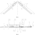
- the flatbed knitting machine includes symmetrical front and back needle beds, which are provided with corresponding needle grooves and knitting needles in the needle grooves.
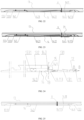
- the knitting needle is generally provided with a hook A 1, a latch A2, and a shaft A3.
- the latch A2 is provided at a back side of the hook A1 and is rotatable to close the hook A1.
- the shaft A3 includes a stem A31 and a shank A32, which are sequentially arranged in a back portion of the hook.
- the shank A32 extends upward in a width direction from a back side of the stem and thus is wider than the stem.
- a recessed first transfer portion A4 is formed at a joint of a front side of the shank and the back side of the stem.
- the knitting needle moves up and down along the needle groove, such that a loop on the knitting needle moves relative to the knitting needle.
- the loop drives the latch to rotate, thereby closing or opening the latch.
- the two knitting needles in the corresponding needle grooves of the front and back needle beds are required to cooperate with each other to realize the loop transfer.
- the knitting needle on the back needle bed needs to be inserted into the loop on the aforementioned knitting needle of the front needle bed.
- a flat spring A5 with a protrusion A51 is provided at one side of the shaft of the knitting needle.
- the flat spring of the prior knitting needle is accommodated in a recess in one side of the shaft, and the flat spring is basically wholly bent in the length direction of the knitting needle to form a trapezoidal protrusion A51, as shown in FIG. 44 .
- the protrusion A51 has an inner cavity forming a hook insertion slot A511, a back portion of the protrusion A51 connected to a bottom surface of the recess to form a connecting end A512, and a lower end of the front side of the protrusion A51 touching the shaft.
- the flat spring straddles the stem A31 and the shank A32 and has a wide section and a narrow section, and a portion corresponding to the shank A32 is wider than a portion corresponding to the stem A31.
- a recessed second transfer portion A52 is formed at a joint of the wide section and the narrow section, and a position of the second transfer portion A52 corresponds to a position of the first transfer portion A4.
- the loop on the knitting needle slides from a front inclined surface A51b of the protrusion to a position, corresponding to the first and second transfer portions, on a top end surface A51a of the protrusion A51, thereby being stretched.
- the protrusion must be higher than a corresponding side surface of the shaft.
- the knitting needle corresponding to the aforementioned knitting needle is inserted into the hook insertion slot A511 from below the hook insertion slot and is inserted into the loop that is hung on the aforementioned knitting needle.
- the knitting needle of the back needle bed moves relative to the length direction of the knitting needle of the front needle bed. Therefore, the hook insertion slot must be long enough to provide a movement space of an appropriate length.
- the front inclined surface is required to be gradual or have a small inclination.
- the back inclined surface A51c is also required to have a small inclination.
- the protrusion will be excessively long, resulting in poor rigidity. The protrusion will be easily deformed when the loop is drawn obliquely or transversely, which will hinder the insertion of the knitting needle, thereby reducing the reliability of insertion.
- the protrusion is required to have an enough height.
- the loop will be hung on the protrusion, thereby causing the loop to be overstretched, making it unsuitable for high-density knitting.
- the latch of the knitting needle to receive the loop may not be opened by the lower end of the hook insertion slot or the lower end of the shaft of the knitting needle that cooperates with it to transfer the loop. Instead, it is usually opened by the loop to be transferred.
- the latch of the knitting needle is opened by the loop, the front end of the latch is often poked into the knitting thread composed of multiple strands of yarn, resulting in a single yarn" problem to cause a flaw in the fabric.
- US2111476A discloses a stitch transfer mechanism for knitting machines. Particularly, it particularly discloses an improved dial needle for use upon rib knitting machines capable of transferring stitch loops from cylinder needles to dial needles, and vice versa.
- the primary object is the provision of an improved knitting machine needle, which may be either of the dial or cylinder type, having an improved stitch loop expanding eye and associated stitch loop extending shoulder there-on capable of expanding and extending a stitch loop so that it may be transferred to a complementary needle of another set of needles, without the use of transfer bits or other relatively movable parts.
- EP1627943A1 discloses a transfer needle with an element mounted for sliding movement in the longitudinal direction relative thereto.
- an objective of the present invention is to provide a knitting needle.
- the present invention as defined in claim 1, adopts the following technical solution.
- the knitting needle is provided for a needle groove of a front or back needle bed of a flatbed knitting machine, and is cooperative with another knitting needle in a corresponding needle groove of a back or front needle bed, where the knitting needle includes:
- the flat spring is further provided with a deformation surface located between a back side of the protrusion and a front side of the fixed connecting end.
- the deformation surface and the protrusion are not exposed outside the recess, or the deformation surface and the protrusion have a portion exposed outside the recess, where the portion exposed outside the recess is elastically pressed into the recess by the needle groove or is suitable to be located in a depression at a corresponding side of the needle groove.
- the deformation surface is configured to be elastically deformed to drive the protrusion to expand outward, such that a loop hung on the first transfer portion and the second transfer portion is stretched.
- the flat spring of the knitting needle is provided with the deformation surface.
- the knitting needle inserted between the flat spring and the shaft causes the deformation surface to be elastically deformed to rotate outward, to drive the protrusion to expand outward, such that the loop hung on the first transfer portion and the second transfer portion is stretched.
- This design achieves the purpose of loop stretching.
- it can reduce the length of the protrusion, increase the rigidity of the protrusion, and improve the stability of the hook insertion slot formed by the inner cavity of the protrusion.
- the deformation surface and the protrusion can sink into the recess at one side of the shaft in a natural state or when pressed by the needle groove.
- the whole flat spring is arranged in the needle groove without any portion exposed outside the recess, thereby reducing the overall width of the knitting needle, such that more knitting needles can be provided on a needle plate in a transverse direction to adapt to the high-density knitting of the flatbed knitting machine and to facilitate placement of the knitting needles in the needle grooves.
- Both or either of the deformation surface and the protrusion may have a portion exposed outside the recess, and the portion exposed outside the recess is located in the depression provided at the corresponding side of the needle groove, so as to meet different knitting needs.
- the present disclosure further adopts the following technical solution.
- the deformation surface is a bending surface that is bent outward. At least one outer end portion higher than the lower ends of the protrusion and located at the front side of the connecting end, and an inclined portion between the front side of the outer end portion and the back side of the protrusion, are formed by bending. Thus, there is a space between the deformation surface and the bottom surface of the recess, which facilitates the elastic deformation of the deformation surface.
- the deformation surface is a flat surface, and the flat surface may touch the bottom surface of the recess, or the deformation surface may be at a certain angle with the bottom surface of the recess.
- a slot depth formed between a top end surface and a bottom end surface of the hook insertion slot is smaller than a thickness of the hook.
- a lower end of the hook insertion slot is provided with a needle groove guide portion for easy insertion of the hook, and/or a front end of the hook is provided with a hook guide portion for easy insertion into the hook insertion slot.
- the bottom of the flat spring protrudes downward at a position corresponding to a front side of the second transfer portion to form a latch opening portion for opening the latch of the knitting needle entering the hook insertion slot.
- This design avoids the "single yarn" problem that may occur when the latch is opened by the loop moving relative to the knitting needle during loop transfer.
- the needle groove guide portion is an inclined surface, where the inclined surface is provided on the bottom surface of the recess, located at the lower end of the hook insertion slot, and inclined backward, such that a lower end opening of the hook insertion slot is shaped as a bell mouth for easy insertion of the hook.
- This design facilitates the hook to be smoothly guided into the hook insertion slot.
- the front end of the hook of the knitting needle is shaped as an arc or a trapezoid that is gradually widened from narrow to wide, with a narrowest front portion narrower than the slot depth.
- This design enables the front end of the hook to be inserted into the hook insertion slot easily and smoothly.
- the deformation surface and the protrusion correspond to positions of a front portion of the shank and a back portion of the stem, respectively.
- the front portion of the deformation surface protrudes upward from the back side of the protrusion in a width direction, such that the second transfer portion is located at a joint of the deformation surface and the protrusion.
- This design minimizes the length of the protrusion and increases the rigidity of the protrusion.
- the deformation surface is longer than the protrusion.
- the deformation of the deformation surface is deformation of outward rotation, so the amount of elastic deformation is increased by increasing the length of the deformation surface, thereby improving the loop stretching effect.
- embodiments 1 to 6 correspond to technical solutions submitted for the first priority (January 21, 2020) of the present application, which are the same as those submitted in the first application (January 14, 2020), where the deformation surface and the protrusion of the flat spring sink into the recess in one side of the shaft and are not exposed outside (or not protruded out) of the recess (or a corresponding side surface of the shaft).
- Embodiments 7 to 11 correspond to the technical solutions submitted for the second priority (August 10, 2020) and added relative to the first application, where the deformation surface and the protrusion of the flat spring may be exposed outside the recess, but the exposed portion can be pressed into the recess by the needle groove.
- Embodiment 12 corresponds to the technical solution submitted by the present application for the third priority and added relative to the technical solutions submitted for the first priority and the second priority, where the deformation surface and the protrusion of the flat spring may be exposed outside the recess, and the exposed portion can be accommodated in the depression provided at the corresponding side of the needle groove.
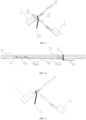
- knitting needles are arranged in corresponding needle grooves of a front needle bed 91 and a back needle bed 92 of a flatbed knitting machine. If any needle groove 911 of the front needle bed 91 is provided with a knitting needle 1, then a knitting needle 2 is provided in a needle groove 921 of the back needle bed 92 corresponding to the needle groove 911.
- the knitting needle 1 and the knitting needle 2 have exactly the same structure, and the knitting needle 1 and the knitting needle 2 are required to cooperate with each other to perform loop transfer.
- the following embodiments take the knitting needle 1 as an example to illustrate the structure of the knitting needle of the present disclosure.
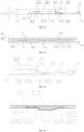
- the knitting needle 1 includes a hook 11, a latch 12, and a shaft 13 including a stem 131 and a shank 132. These elements are all found in the prior knitting needles.
- the shank 132 is wider than the stem 131, and a recessed first transfer portion 15 is formed at a joint of the shank 132 and the stem 131.
- a recess 133 is provided in a side of the shaft of the knitting needle 1. The recess 133 straddles the corresponding side surfaces of the stem 131 and the shank 132.
- a flat spring 14 sinks into the recess 133.
- the flat spring 14 has a wide portion and a narrow portion, and a recessed second transfer portion 143 is formed at a joint of the wide portion and the narrow portion.
- the position of the second transfer portion 143 corresponds to the position of the first transfer portion 15.
- a deformation surface and a protrusion correspond to positions of a front portion of the shank and a back portion of the stem, respectively.
- the front portion of the deformation surface protrudes upward in a width direction from a back side of the protrusion, such that the second transfer portion is located at a joint of the deformation surface and the protrusion.
- a loop X is hung at the position corresponding to the first transfer portion and the second transfer portion, such that the loops hung on the stem are adapted to the original loop density without being excessively large.
- This design is particularly suitable for high-density knitting.
- the bottom of the flat spring is not raised and is in a flat state, higher than the bottom of the shaft.
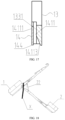
- a back portion of the flat spring is connected to a bottom surface 1331 of the recess 133 by welding to form a connecting end 145.
- a front portion of the flat spring is bent outward in a length direction of the shaft to form a protrusion 141.
- a lower end of a front side of the protrusion touches the bottom surface 1331 of the recess, and an inner cavity of the protrusion 141 forms a hook insertion slot 1411.
- a deformation surface 142 is further provided between a back side of the protrusion and a front side of the connecting end.
- the elastic deformation of the deformation surface drives the protrusion to expand outward so as to achieve the purpose of stretching the loop.
- the deformation surface in this embodiment is designed as follows.
- the deformation surface 142 is formed by a triangular bending to form an outer end portion 1421 and an inclined portion 1422 of a bending point (if necessary, it may also be formed by multiple triangular bending to form multiple bending points).
- the outer end portion 1421 is higher than the lower ends of the protrusion 141 and located at the front side of the connecting end 145.
- the inclined portion 1422 is located between a front side of the outer end portion 1421 and the back side of the protrusion and is inclined from the outside to the inside, such that there is a space between the deformation surface 142 and the bottom surface 1331 of the recess.
- a top end surface 14111 of the protrusion 141, and an outermost end of the deformation surface 142, i.e. the outer end portion 1421, are not protruded (not exposed) out of an outermost side surface of the shaft, that is, they are not higher than a most protruding surface of the corresponding side of the shaft.
- a slot depth h is formed between an inner side of the top end surface 14111 and a bottom end surface (i.e., the bottom surface 1331 of the recess) of the hook insertion slot 1411, and the slot depth h is smaller than a thickness of the hook.
- a lower end of the hook insertion slot 1411 is provided with a needle groove guide portion which facilitates the insertion of the hook.
- the guide portion is an inclined surface 14113 provided at the lower end of the hook insertion slot.
- the inclined surface 14113 is inclined backward from the bottom surface 1331 of the recess, such that a lower end opening of the hook insertion slot is shaped as a bell mouth.
- a front end of the hook of the knitting needle is shaped as an arc that is gradually widened from narrow to wide. As shown in FIG. 5 , it is obvious that a narrowest portion of the front end is smaller than the slot depth to form a hook guide portion, which facilitates the front end of the hook to be inserted into the hook insertion slot.
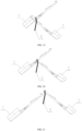
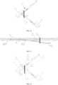
- a corresponding knitting needle e.g. the knitting needle 2 that cooperates with a knitting needle (e.g. the knitting needle 1) currently holding a loop is inserted into the hook insertion slot of the knitting needle 1, such that the deformation surface is elastically deformed to rotate relative to the bottom surface of the recess, to drive the protrusion to expand outward to achieve the purpose of stretching the loop on the knitting needle 1.
- the knitting needle 1 holding the loop to be transferred moves upward along the needle groove, and the loop X on the knitting needle 1 moves relatively to the positions of the first transfer portion 15 and the second transfer portion.
- the knitting needle 2 is inserted into the hook insertion slot 1411 via the needle groove guide portion from the lower portion of the protrusion 141 of the knitting needle 1.
- the hook portion of the knitting needle 2 causes the deformation surface of the knitting needle 1 to be deformed to rotate outward, and drives the protrusion of the knitting needle 1 to expand outward, such that the loop X is stretched.
- the latch 22 of the knitting needle 2 is possible to touch the lower end of the hook insertion slot 1411 to be opened, or not touch the lower end of the hook insertion slot 1411 to not be opened. If the latch is opened, please refer to Embodiment 3. If the latch is not opened, when the hook of the knitting needle 2 enters the loop X through the hook insertion slot 1411, the loop X touches the closed latch 22 of the knitting needle 2, as shown in FIG. 8 . As the knitting needle 2 moves upward relative to the knitting needle 1 along the needle groove, the loop X opens the latch 22, as shown in FIG. 9 . The knitting needle 2 moves to a position between the deformation surface and the bottom surface of the recess, as shown in FIG. 10 .
- the two knitting needles continue to move in cooperation, and the loop X completely enters the hook 21 of the knitting needle 2, as shown in FIG. 11 .
- the hook 21 carries the loop X to move out of the flat spring from the lower end of the front side of the protrusion 141, as shown in FIG. 12 .
- the loop X closes the latch 12 of the knitting needle 1, such that the loop X is completely moved out of the knitting needle 1 and completely transferred to the knitting needle 2, as shown in FIG. 13 .
- the knitting needle of this embodiment has basically the same structure as that of Embodiment 1, with the exception that the lower end of the hook insertion slot 1411 formed by the inner cavity of the protrusion 141 of the flat spring 14 is not provided with a needle groove guide portion.
- the inclined surface 14113 inclined backward from the bottom surface 1331 of the recess is not provided on the bottom end surface (i.e. the bottom surface 1331 of the recess) of the hook insertion slot 1411, as shown in FIG. 14 .
- the smooth insertion of the corresponding knitting needle e.g.
- the front end of the hook of the knitting needle is shaped as a trapezoid that is gradually widened from narrow to wide, with a narrowest portion smaller than the slot depth, and the front end is tapered, as shown in FIG. 15 , which is convenient for hook insertion.
- the knitting needle 1 of this embodiment has the same hook 11, latch 12 and shaft 13 as those of Embodiment 1.
- the flat spring 14 sinks into the recess 133 in one side of the shaft, and the recess 133 straddles the corresponding side surfaces of the stem 131 and the shank 132.
- the flat spring 14 is provided with a protrusion 141 and a deformation surface 142 at a back side of the protrusion.
- the structure of the deformation surface 142 is the same as that of Embodiment 1, that is, the deformation surface 142 has an outer end portion 1421 and an inclined portion 1422, as shown in FIG. 3 in Embodiment 1.
- the top end surface of the protrusion 141 and the most protruding portion (i.e. the outer end portion 1421) of the deformation surface 142 are not protruded out of the outermost surface of the corresponding side of the shaft.
- the lower end of the front side of the protrusion touches the bottom surface 1331 of the recess, and the inner cavity of the protrusion 141 forms the hook insertion slot, and the slot depth is smaller than the thickness of the hook ( FIG. 4 ).
- the bottom of the flat spring 14 is not in a flat state, but protrudes downward at a position corresponding to the front side of the second transfer portion to form a latch opening portion 144.
- the latch opening portion 144 is not lower than the bottom of the shaft 13, and is configured to open the latch of the knitting needle entering the hook insertion slot.
- This design solves the problem that the latch of the knitting needle to be inserted into the loop cannot be reliably opened when the knitting needle is inserted into the hook insertion slot of the knitting needle carrying the loop, thereby effectively preventing the "single yarn” problem.
- the lower end of the hook insertion slot 1411 formed by the inner cavity of the protrusion 141 is provided with a needle groove guide portion formed by the inclined surface 14113 inclined backward from the bottom surface 1331 of the recess, such that the lower end opening of the hook insertion slot 1411 is shaped as a bell mouth for easy insertion of the hook, as shown in FIG. 17 .
- the front end of the hook is also shaped as an arc, as shown in FIG. 5 , such that the hook can be easily inserted into the hook insertion slot.
- other structures of the knitting needle such as the first transfer portion, the second transfer portion, and the connection mode between the flat spring and the shaft, are the same as those in Embodiment 1, and thus will not be repeated here.
- the latch 22 touches the latch opening portion 144 protruding downward and is thus opened, as shown in FIG. 18 .
- the deformation surface of the flat spring of the knitting needle 1 is deformed to rotate outward, thereby driving the protrusion to expand outward, such that the loop X is stretched, as shown in FIG. 7 .
- the knitting needle 1 and the knitting needle 2 move with each other according to a set program.
- the hook 21 of the knitting needle 2 with the latch 22 open enters the loop X hung on the first transfer portion and the second transfer portion.
- the knitting needle 2 is completely inserted into the loop X, as shown in FIG. 19 .
- the hook 21 of the knitting needle 2 carries the loop X to move out of the flat spring from the lower end of the front side of the protrusion 141, as shown in FIG. 20 .
- the loop X moves relative to the stem and closes the latch 12 of the knitting needle 1.
- the loop X moves out of the knitting needle 1 and falls completely on the knitting needle 2, as shown in FIG. 21 .
- the knitting needle of this embodiment has basically the same structure as that of Embodiment 3, and differs from Embodiment 3 only in the bending structure of the flat spring 14.
- the flat spring 14 of the knitting needle is bent in a trapezoidal shape to form an outer end portion 1421 with a bending surface, and the outer end portion 1421 is higher than the lower ends of the protrusion and is located at the front side of the connecting end, as shown in FIG. 22 .
- the knitting needle 2 is inserted into the hook insertion slot 1411 of the knitting needle 1 carrying the loop X.
- the deformation surface 142 of the knitting needle 1 is deformed to rotate outward to drive the protrusion 141 to expand outward, such that the loop X is stretched, as shown in FIG. 23 .
- the following transfer process is shown in FIGS.
- the latch opening portion 144 opens the latch, the hook 21 enters the loop X and is completely inserted into the loop X, then the loop X is removed by the knitting needle 2 and falls completely on the knitting needle 2.
- the knitting needle of this embodiment has the same hook 11, latch 12 and shaft 13 as those of Embodiment 1.
- the flat spring 14 sinks into the recess 133 in one side of the shaft.
- the flat spring 14 is provided with the protrusion 141, the deformation surface 142 at the back side of the protrusion, and the latch opening portion 144 protruding downward at a position corresponding to the front side of the second transfer portion.
- the latch opening portion 144 is flush with the bottom of the shaft 13, and is configured to open the latch of the knitting needle entering the hook insertion slot.
- the top end surface of the protrusion 141 does not protrude out of the outermost surface of the corresponding side of the shaft.
- the inner cavity of the protrusion 141 forms the hook insertion slot 1411, and the slot depth h is smaller than the thickness of the hook ( FIG. 4 ).
- the lower end of the hook insertion slot 1411 is provided with the inclined surface 14113 inclined backward from the bottom surface 1331 of the recess to form the needle groove guide portion, and the lower end opening of the hook insertion slot 1411 is shaped as a bell mouth for easy insertion of the hook.
- the difference between the flat spring 14 in this embodiment and Embodiment 3 is that the deformation surface is not bent.
- the deformation surface is a flat surface extending backward from the back side of the protrusion and touches the bottom surface 1331 of the recess 133.
- the front portion of the deformation surface protrudes upward in the width direction from the back side of the protrusion, such that the second transfer portion is located at the joint of the deformation surface and the protrusion.
- the knitting needle 2 inserted into the inner side of the protrusion moves at the hook insertion slot and between the deformation surface and the bottom surface of the recess. As the knitting needle 2 is inserted into the hook insertion slot, the deformation surface is deformed to rotate.
- the knitting needle 2 enters the position between the deformation surface and the bottom surface of the recess 133 from the hook insertion slot to increase the deformation amount.
- This structure is applicable for knitting that requires a large amount of loop stretching.
- other structures of the knitting needle such as the first transfer portion and the connection mode between the flat spring and the shaft, are the same as those in Embodiment 3, and thus will not be repeated here.
- the hook of the knitting needle 2 with the latch open enters a position between the deformation surface and the bottom surface of the recess 133 from the hook insertion slot, and then enters the loop X hung on the first transfer portion and the second transfer portion, as shown in FIG. 26 .
- the deformation surface is deformed to rotate outward again, which increases the magnitude of the rotational deformation, as shown in FIG. 27 , such that the loop X is stretched again.
- the hook 21 of the knitting needle 2 is completely inserted into the loop X, as shown in FIG. 28 .
- the hook 21 carries the loop X to move out of the flat spring from the lower end of the front side of the protrusion 141, as shown in FIG. 29 .
- the loop X closes the latch 12 of the knitting needle 1 and thus moves completely out of the knitting needle 1, as shown in FIG. 30 .
- the slot depth h formed between the top end surface 14111 and the bottom end surface (i.e. the bottom surface 1331 of the recess) of the hook insertion slot 1411 is not less than the thickness ⁇ of the hook.
- the other structures of this embodiment are the same as those of Embodiment 5.
- the flat spring 14 may not be elastically deformed to rotate outward, as shown in FIG. 31 .
- the deformation surface 142 is elastically deformed to rotate outward to drive the protrusion 141 to expand outward, such that the loop X on the first transfer portion and the second transfer portion is stretched, as shown in FIG. 32 .
- the deformation surface 142 is a bending surface formed by triangular bending outward.
- the bent end can be approximated as a bending point (the bent end protrudes from the side surface of the corresponding side of the shaft to form the outer end portion 1421).
- the deformation surface 142 and the protrusion 141 both have a portion exposed outside the recess 133 in a natural state without external force, or one of the deformation surface 142 and the protrusion 141 has a portion exposed outside the recess 133 (not shown in the figure).
- the portion exposed outside the recess 133 is restrained by the needle groove 911 (which corresponds to a wall 9111), the portion exposed outside the recess 133 is elastically pressed into the recess 133, as shown in FIG. 34 .
- the loop transfer process of the knitting needle is shown in FIGS. 6, 8 , 9, 11 , 12, and 13 .
- the knitting needle of this embodiment has the same basic structure as that of Embodiment 7, with the exception that in this embodiment, the bottom of the flat spring 14 is not in a flat state, but protrudes downward at a position corresponding to the front side of the second transfer portion to form the latch opening portion 144, as shown in FIG. 16 .
- the latch opening portion 144 is not lower than the bottom of the shaft 13, and is configured to open the latch of the knitting needle entering the hook insertion slot.
- the knitting needle 2 is inserted into the needle groove guide portion from below the hook insertion slot 1411 of the knitting needle 1.
- the knitting needle 1 moves upward, in other words, the knitting needle 2 moves downward relative to the knitting needle 1.
- the latch 22 touches the latch opening portion 144 protruding downward and is thus opened, as shown in FIG. 18 .
- FIGS. 18 to 21 please refer to FIGS. 18 to 21 .
- the structure of the knitting needle of this embodiment is based on Embodiment 8, and differs from Embodiment 8 only in the bending structure of the flat spring 14.
- the protrusion 141 of the flat spring 14 of the knitting needle is an arc-shaped protrusion.
- the deformation surface between the front side of the connecting end of the flat spring and the bottom surface of the recess and the back side of the protrusion 141 is a bending surface formed by bending outward in an arc shape. Due to the large radius of curvature of the arc, the bent end is approximately flat.
- Both or either of the deformation surface 142 and the protrusion 141 may be exposed outside the recess 133 in a natural state without external force, but the exposed portion can be elastically pressed in the recess, as shown in FIG. 36 .
- the loop transfer process is shown in FIGS. 18 to 21 .
- the structure of the knitting needle of this embodiment is based on Embodiment 8, and differs from Embodiment 8 only in the bending structure of the deformation surface of the flat spring 14.
- the deformation surface 142 is a flat surface.
- the deformation surface 142 extends forward from the connecting end 145 to the back side of the protrusion 141 and touches the bottom surface 1331 of the recess 133.
- the protrusion 141 connected to the front portion of the deformation surface 142 is exposed outside the recess 133, as shown in FIG. 37 , but the exposed portion can be elastically pressed into the recess, as shown in FIG. 38 .
- FIGS. 18 to 21 For the loop transfer process, please refer to FIGS. 18 to 21 .
- the knitting needle of this embodiment is basically the same as that of Embodiment 10, with the exception that the flat deformation surface 142 does not touch the bottom surface of the recess, and is slightly inclined outward relative to the bottom surface of the recess.
- the protrusion is exposed outside the recess 133, as shown in FIG. 39 , but as the same as in the aforementioned embodiment, the exposed portion can also be pressed into the recess 133 through elastic deformation, as shown in FIG. 40 .
- the loop transfer process please refer to FIGS. 18 to 21 .
- FIG. 41 The front view of the knitting needle of this embodiment is shown in FIG. 41 . Similar to the structure of the knitting needle of Embodiment 3 shown in FIG. 16 , in this embodiment, the bottom of the flat spring 14 is provided with a latch opening portion 144 protruding downward at a position corresponding to the front side of the second transfer portion 143.
- the deformation surface 142 of the flat spring 14 is a bending surface that is bent outward to form an outer end portion 1421, as shown in FIG. 42 . In a natural state, the bending surface and the protrusion 141 both have a portion exposed outside the recess 133 of the shaft.
- the outer end portion 1421 of the deformation surface 142 and the top end surface 14111 of the protrusion are both exposed outside the recess.
- the needle groove 911 configured to accommodate the knitting needle is provided with a depression 9113 in its side surface.
- the portion of the deformation surface 142 and the protrusion 141 of the flat spring that is exposed outside the recess 133 is located in the depression 9113 in the side surface of the needle groove.
- the knitting needle is adapted to the knitting of a corresponding gauge.
- FIGS. 18 to 21 please refer to FIGS. 18 to 21 .
- the portion of the flat spring exposed outside the recess is not limited to exposed portions of both the deformation surface and the protrusion, and may also be an exposed portion of either the deformation surface or the protrusion. However, any exposed portion is located in the depression 9113 in the side surface of the needle groove.
- the position of the second transfer portion 143 of the flat spring 14 corresponds to the position of the first transfer portion 15 of the knitting needle.
- the deformation surface 142 and the protrusion 141 correspond to positions at the front portion of the shank and the back portion of the stem, respectively.
- the front portion of the deformation surface protrudes upward in the width direction from the back side of the protrusion, such that the second transfer portion is located at the joint of the deformation surface and the protrusion.
- the flat spring is provided with the deformation surface, and the elastic deformation of the deformation surface drives the protrusion to expand outward for loop stretching. Therefore, the knitting needle has desired density adaptability.
- the elastic deformation of the deformation surface can make the flat spring pressed in the recess on the shaft, such that the overall width of the knitting needle is narrowed to adapt to high-density knitting.
- the elastic deformation of the deformation surface can also make the flat spring released out of the shaft to suit different knitting needs.
Landscapes
- Engineering & Computer Science (AREA)
- Textile Engineering (AREA)
- Knitting Machines (AREA)
- Materials For Medical Uses (AREA)
Claims (9)
- Eine Stricknadel (1), die für eine Nadelrinne (911) eines vorderen oder hinteren Nadelbetts (91) einer Flachstrickmaschine vorgesehen ist und mit einer anderen Stricknadel (2) in einer entsprechenden Nadelrinne (921) eines hinteren oder vorderen Nadelbetts (92) zusammenwirkt, wobei die Stricknadel (1) umfasst:einen Haken (11);eine Zunge (12), die an einer Rückseite des Hakens (11) vorgesehen ist und drehbar ist, um den Haken (11) zu schließen;einen Schaft (13), der einen Schenkel (131) und einen Hals (132) umfasst, die in einem hinteren Abschnitt des Hakens (11) aufeinanderfolgend angeordnet sind, wobei der Hals (132) breiter ist als der Schenkel (131);ein eingesenkter erster Übertragungsabschnitt (15), der an einer Verbindung des Schenkels (131) und des Halses (132) gebildet ist;eine Aussparung (133), die in einer Seite des Schafts (13) vorgesehen ist;eine Flachfeder (14), die auf einer Bodenfläche (1331) der Aussparung (133) angeordnet ist und einen vorderen Abschnitt, der in Längsrichtung des Schafts (13) nach außen gebogen ist, um einen Vorsprung (141) auszubilden, und einen hinteren Abschnitt auszubilden, der durch Schweißen fest mit der Bodenfläche (1331) der Aussparung (133) verbunden ist, um ein befestigtes Endstück (145) auszubilden; undeinen Hakeneinführschlitz (1411), der durch einen inneren Hohlraum zwischen dem Vorsprung (141) und der Bodenfläche (1331) der Aussparung (133) ausgebildet wird;dadurch gekennzeichnet, dass:die Flachfeder (14) mit einem vertieften zweiten Übertragungsabschnitt (143) versehen ist;die Flachfeder (14) ist ferner mit einer Verformungsfläche (142) versehen, die sich zwischen einer Rückseite des Vorsprungs (141) und einer Vorderseite des befestigten Endstücks (145) befindet; die Verformungsfläche (142) und der Vorsprung (141) liegen außerhalb der Aussparung (133) nicht frei, oder die Verformungsfläche (142) und der Vorsprung (141) weisen einen außerhalb der Aussparung (133) freiliegenden Abschnitt auf, wobei der außerhalb der Aussparung (133) freiliegende Abschnitt durch die Nadelrinne (911) elastisch in die Aussparung (133) gedrückt wird oder sich in einer Vertiefung an einer entsprechenden Seite der Nadelrinne (911) befindet; undwährend des Maschenübergangs, wenn ein Haken (21) einer anderen Stricknadel (2) in der entsprechenden Nadelrinne (921) durch den Hakeneinführschlitz (1411) in eine Position zwischen der Flachfeder (14) und dem Schaft (13) eingeführt wird und sich in eine Position zwischen der Verformungsfläche (142) und der Bodenfläche (1331) der Aussparung (133) bewegt, wobei die Verformungsfläche (142) so konfiguriert ist, dass sie elastisch verformt wird, um den Vorsprung (141) zum Ausdehnen nach außen anzutreiben, so dass eine Schlaufe, die an dem eingesenkten ersten Übertragungsabschnitt (15) und an dem eingesenkten zweiten Übertragungsabschnitt (143) hängt, gedehnt wird.
- Stricknadel (1) nach Anspruch 1, dadurch gekennzeichnet, dass die Verformungsfläche (142) eine Biegefläche ist, wobei die Biegefläche nach außen gebogen ist.
- Stricknadel (1) nach Anspruch 1, dadurch gekennzeichnet, dass die Verformungsfläche (142) eine flache Oberfläche ist.
- Stricknadel (1) nach einem der Ansprüche 2 bis 3, dadurch gekennzeichnet, dass eine Schlitztiefe (h), die zwischen einer oberen Endfläche (14111) und einer unteren Endfläche des Hakeneinführschlitzes (1411) ausgebildet ist, kleiner ist als eine Dicke des Hakens (11 ; und ein unteres Ende des Hakeneinführschlitzes (1411) mit einem Nadelrinnen-Führungsabschnitt für das einfache Einführen des Hakens (11) versehen ist und/oder ein vorderes Ende des Hakens (11) mit einem Hakenführungsabschnitt für das einfache Einführen in den Hakeneinführschlitz (1411) versehen ist.
- Stricknadel (1) nach Anspruch 4, dadurch gekennzeichnet, dass ein unteres Ende der Flachfeder (14) an einer Position, die einer Vorderseite des eingesenkt angeordneten zweiten Übertragungsabschnitts (143) entspricht, nach unten hervorsteht, um einen Zungenöffnungsabschnitt (144), der das Öffnen der Zunge der in den Hakeneinführschlitz (1411) eintretenden Stricknadel ermöglicht.
- Stricknadel (1) nach Anspruch 5, dadurch gekennzeichnet, dass der Nadelrinnen-Führungsabschnitt eine geneigte Oberfläche (14113) ist, wobei die geneigte Oberfläche (14113) auf der Bodenfläche (1331) der Aussparung (133) vorgesehen ist, die sich am unteren Ende des Hakeneinführschlitzes (1411) befindet, und nach hinten geneigt ist, so dass eine Öffnung am unteren Ende des Hakeneinführschlitzes (1411) als glockenförmige Öffnung ausgebildet ist, um das Einführen des Hakens (11) zu erleichtern.
- Stricknadel (1) nach Anspruch 5, dadurch gekennzeichnet, dass das vordere Ende der Stricknadel (1) in Dickenrichtung als Bogen oder Trapez geformt ist, das sich allmählich von schmal nach breit verbreitert, wobei der schmalste vordere Abschnitt schmaler als die Schlitztiefe (h) ist.
- Stricknadel (1) nach Anspruch 7, dadurch gekennzeichnet, dass die Verformungsfläche (142) und der Vorsprung (141) den Positionen eines vorderen Abschnitts des Halses (132) bzw. eines hinteren Abschnitts des Schenkels (131) entsprechen; und eine Vorderseite der Verformungsfläche (142) von der Rückseite des Vorsprungs (141) in einer Breitenrichtung nach oben hervorsteht, so dass sich der eingesenkte zweite Übertragungsabschnitt (143) an der Verbindungsstelle der Verformungsfläche (142) und des Vorsprungs (141) befindet.
- Stricknadel (1) nach Anspruch 8, dadurch gekennzeichnet, dass die Verformungsfläche (142) länger ist als der Vorsprung (141).
Applications Claiming Priority (5)
| Application Number | Priority Date | Filing Date | Title |
|---|---|---|---|
| CN202010035779 | 2020-01-14 | ||
| CN202010068906.2A CN111286863A (zh) | 2020-01-14 | 2020-01-21 | 一种织针 |
| CN202010794757.8A CN111793885A (zh) | 2020-01-14 | 2020-08-10 | 一种织针 |
| CN202011314294.7A CN112342674B (zh) | 2020-01-14 | 2020-11-20 | 一种织针 |
| PCT/CN2020/141550 WO2021143532A1 (zh) | 2020-01-14 | 2020-12-30 | 一种织针 |
Publications (4)
| Publication Number | Publication Date |
|---|---|
| EP4083286A1 EP4083286A1 (de) | 2022-11-02 |
| EP4083286A4 EP4083286A4 (de) | 2023-06-07 |
| EP4083286B1 true EP4083286B1 (de) | 2025-02-12 |
| EP4083286C0 EP4083286C0 (de) | 2025-02-12 |
Family
ID=71024284
Family Applications (1)
| Application Number | Title | Priority Date | Filing Date |
|---|---|---|---|
| EP20913491.5A Active EP4083286B1 (de) | 2020-01-14 | 2020-12-30 | Stricknadel |
Country Status (9)
| Country | Link |
|---|---|
| US (1) | US20230046300A1 (de) |
| EP (1) | EP4083286B1 (de) |
| JP (1) | JP7423018B2 (de) |
| KR (1) | KR102659773B1 (de) |
| CN (3) | CN111286863A (de) |
| ES (1) | ES3030327T3 (de) |
| HU (1) | HUE071304T2 (de) |
| PL (1) | PL4083286T3 (de) |
| WO (1) | WO2021143532A1 (de) |
Families Citing this family (2)
| Publication number | Priority date | Publication date | Assignee | Title |
|---|---|---|---|---|
| CN111286863A (zh) * | 2020-01-14 | 2020-06-16 | 冯加林 | 一种织针 |
| CN113699678B (zh) * | 2021-07-12 | 2023-04-28 | 汕头市连兴实业有限公司 | 一种前后针织物旋转编织方法 |
Citations (15)
| Publication number | Priority date | Publication date | Assignee | Title |
|---|---|---|---|---|
| US2111476A (en) | 1936-03-12 | 1938-03-15 | Nolde & Horst Company | Stitch transfer mechanism for knitting machines |
| DE660568C (de) | 1936-04-18 | 1938-05-28 | Reutlinger Strickmaschinenfabr | Flachstrickmaschine zum UEbertragen von Maschen von den Nadeln des einen Nadelbettes auf die des anderen durch die Nadeln selbst |
| DE1585391A1 (de) | 1966-11-25 | 1971-03-04 | Stoll & Co H | Zungennadel fuer Strick-,insbesondere V-Bett-Flachstrickmaschinen zum UEbertragen von Maschen von den Nadeln des einen auf die des anderen Nadelbettes |
| ES223603U (es) | 1976-10-05 | 1976-12-16 | Abril Cullell | Nueva aguja para tricotosa rectilinea. |
| US4178781A (en) | 1978-03-06 | 1979-12-18 | The Torrington Company | Knitting needle |
| DE2847972A1 (de) | 1978-08-28 | 1980-03-13 | Mas Matias Mestre | Maschenuebertragungsnadel fuer wirkmaschinen |
| DE3145708A1 (de) | 1981-01-27 | 1982-08-19 | Matias Soldeu Mestre Mas | Maschenuebertragungsnadel fuer wirk- und strickmaschinen |
| JPS57167796U (de) | 1981-04-15 | 1982-10-22 | ||
| DE3541565A1 (de) | 1984-12-18 | 1986-06-19 | Edouard Dubied & Cie. S.A., Couvet, Neuchâtel | Zungennadel fuer maschenuebertragung |
| EP0764734A1 (de) | 1995-09-25 | 1997-03-26 | Tsai Hsing Lin | Nadelvorrichtung für Strickmaschine |
| EP1464746A1 (de) | 2003-04-03 | 2004-10-06 | H. Stoll GmbH & Co. | Nadel für Strickmaschinen und Verfahren zum Teilen einer Masche |
| EP1627943A1 (de) | 2004-08-17 | 2006-02-22 | H. Stoll GmbH & Co. KG | Halterung eines in Längsrichtung verschiebbaren Teils an einer Umhängenadel für eine Strickmaschine |
| CN201660745U (zh) | 2010-04-16 | 2010-12-01 | 谈兆奎 | 电控自动横机的针板系统 |
| EP3015209A1 (de) | 2014-10-27 | 2016-05-04 | Hugo Kern und Liebers GmbH & Co. KG Platinen- und Federnfabrik | Nadeln oder Platinen für Textilmaschinen sowie Verfahren zur Herstellung einer Nadel oder einer Platine für Textilmaschinen |
| CN107354575A (zh) | 2017-08-09 | 2017-11-17 | 南通市光阳针业有限公司 | 一种新型移圈织针 |
Family Cites Families (21)
| Publication number | Priority date | Publication date | Assignee | Title |
|---|---|---|---|---|
| GB478969A (en) * | 1936-07-27 | 1938-01-27 | M B C Vendors Ltd | Improvements in or relating to the manufacture of knitted fabric and articles and loop transferring instruments employed therein |
| DE2043566A1 (de) * | 1969-09-03 | 1971-04-08 | Kohorn, Alfred Oswald, New York, NY (VStA) | Nadel fur mit hoher Geschwindigkeit arbeitende Rundstrickmaschinen |
| DE3927054C2 (de) * | 1989-08-16 | 1997-02-20 | Stoll & Co H | Nadel für Strickmaschinen |
| JPH0578962A (ja) * | 1991-09-17 | 1993-03-30 | Shima Seiki Mfg Ltd | 編機用コンパウンドニードル |
| DE19905668C2 (de) * | 1999-02-11 | 2001-01-25 | Groz Beckert Kg | Umhängenadel zur Maschenübertragung |
| DE10227533C1 (de) * | 2002-06-20 | 2003-12-11 | Groz Beckert Kg | Nadel mit Umhängefeder |
| DE502004006053D1 (de) * | 2004-08-17 | 2008-03-13 | Stoll H Gmbh & Co Kg | Umhängenadel für eine Strickmaschine |
| CN100500968C (zh) * | 2004-11-26 | 2009-06-17 | H.斯托尔两合公司 | 在针织机的移圈针上的部件的固定装置 |
| US7614255B2 (en) * | 2005-04-06 | 2009-11-10 | Groz-Beckert Kg | Cutting needle |
| EP1757721B2 (de) * | 2005-08-26 | 2015-12-30 | H. Stoll GmbH & Co. KG | Verfahren zum Umhängen von Maschen |
| CN2841704Y (zh) * | 2005-09-26 | 2006-11-29 | 陈国标 | 移圈针 |
| JP5364379B2 (ja) * | 2005-11-18 | 2013-12-11 | サントニ エッセ.ピ.ア. | 靴下編機等のためのその針自身から隣接する針へステッチを移す針 |
| DE502006006452D1 (de) * | 2006-08-11 | 2010-04-29 | Groz Beckert Kg | Zungennadel für maschenbildende Textilmaschine |
| JP5032822B2 (ja) * | 2006-10-06 | 2012-09-26 | 株式会社島精機製作所 | べら針 |
| ITMI20080121A1 (it) * | 2008-01-28 | 2009-07-29 | Santoni & C Spa | Ago per operare il trasferimento di punti di maglia dallo stesso ago ad aghi adiacenti per macchine per maglieria, calzetteria o simili. |
| ITMI20080123A1 (it) * | 2008-01-28 | 2009-07-29 | Santoni & C Spa | Ago per operare il trasferimento di punti di maglia dallo stesso ago ad aghi adiacenti per macchine per maglieria, calzetteria o simili. |
| IT1403218B1 (it) * | 2011-01-05 | 2013-10-17 | Santoni & C Spa | Macchina circolare monocilindro per calze da uomo, del tipo con aghi sul platorello |
| CN207295091U (zh) * | 2017-08-09 | 2018-05-01 | 南通市光阳针业有限公司 | 一种新型移圈织针 |
| CN208414780U (zh) * | 2018-04-17 | 2019-01-22 | 陈一鸣 | 针织机防压瘪移圈簧片舌针 |
| CN109750413B (zh) * | 2019-02-28 | 2023-09-29 | 宁波慈星股份有限公司 | 一种用于横机的复合针 |
| CN111286863A (zh) * | 2020-01-14 | 2020-06-16 | 冯加林 | 一种织针 |
-
2020
- 2020-01-21 CN CN202010068906.2A patent/CN111286863A/zh active Pending
- 2020-08-10 CN CN202010794757.8A patent/CN111793885A/zh active Pending
- 2020-11-20 CN CN202011314294.7A patent/CN112342674B/zh active Active
- 2020-12-30 ES ES20913491T patent/ES3030327T3/es active Active
- 2020-12-30 KR KR1020227027729A patent/KR102659773B1/ko active Active
- 2020-12-30 EP EP20913491.5A patent/EP4083286B1/de active Active
- 2020-12-30 HU HUE20913491A patent/HUE071304T2/hu unknown
- 2020-12-30 US US17/792,730 patent/US20230046300A1/en active Pending
- 2020-12-30 JP JP2022540967A patent/JP7423018B2/ja active Active
- 2020-12-30 PL PL20913491.5T patent/PL4083286T3/pl unknown
- 2020-12-30 WO PCT/CN2020/141550 patent/WO2021143532A1/zh not_active Ceased
Patent Citations (17)
| Publication number | Priority date | Publication date | Assignee | Title |
|---|---|---|---|---|
| US2111476A (en) | 1936-03-12 | 1938-03-15 | Nolde & Horst Company | Stitch transfer mechanism for knitting machines |
| DE660568C (de) | 1936-04-18 | 1938-05-28 | Reutlinger Strickmaschinenfabr | Flachstrickmaschine zum UEbertragen von Maschen von den Nadeln des einen Nadelbettes auf die des anderen durch die Nadeln selbst |
| DE1585391A1 (de) | 1966-11-25 | 1971-03-04 | Stoll & Co H | Zungennadel fuer Strick-,insbesondere V-Bett-Flachstrickmaschinen zum UEbertragen von Maschen von den Nadeln des einen auf die des anderen Nadelbettes |
| ES223603U (es) | 1976-10-05 | 1976-12-16 | Abril Cullell | Nueva aguja para tricotosa rectilinea. |
| US4178781A (en) | 1978-03-06 | 1979-12-18 | The Torrington Company | Knitting needle |
| DE2847972A1 (de) | 1978-08-28 | 1980-03-13 | Mas Matias Mestre | Maschenuebertragungsnadel fuer wirkmaschinen |
| DE2847972C2 (de) | 1978-08-28 | 1981-12-24 | Matias Soldeu Mestre Mas | Flachstrickmaschine mit Umhängenadeln zur Maschenübertragung |
| DE3145708C2 (de) | 1981-01-27 | 1985-02-07 | Matias Soldeu Mestre Mas | Umhängenadel für Flachstrickmaschinen |
| DE3145708A1 (de) | 1981-01-27 | 1982-08-19 | Matias Soldeu Mestre Mas | Maschenuebertragungsnadel fuer wirk- und strickmaschinen |
| JPS57167796U (de) | 1981-04-15 | 1982-10-22 | ||
| DE3541565A1 (de) | 1984-12-18 | 1986-06-19 | Edouard Dubied & Cie. S.A., Couvet, Neuchâtel | Zungennadel fuer maschenuebertragung |
| EP0764734A1 (de) | 1995-09-25 | 1997-03-26 | Tsai Hsing Lin | Nadelvorrichtung für Strickmaschine |
| EP1464746A1 (de) | 2003-04-03 | 2004-10-06 | H. Stoll GmbH & Co. | Nadel für Strickmaschinen und Verfahren zum Teilen einer Masche |
| EP1627943A1 (de) | 2004-08-17 | 2006-02-22 | H. Stoll GmbH & Co. KG | Halterung eines in Längsrichtung verschiebbaren Teils an einer Umhängenadel für eine Strickmaschine |
| CN201660745U (zh) | 2010-04-16 | 2010-12-01 | 谈兆奎 | 电控自动横机的针板系统 |
| EP3015209A1 (de) | 2014-10-27 | 2016-05-04 | Hugo Kern und Liebers GmbH & Co. KG Platinen- und Federnfabrik | Nadeln oder Platinen für Textilmaschinen sowie Verfahren zur Herstellung einer Nadel oder einer Platine für Textilmaschinen |
| CN107354575A (zh) | 2017-08-09 | 2017-11-17 | 南通市光阳针业有限公司 | 一种新型移圈织针 |
Non-Patent Citations (11)
| Title |
|---|
| ANONYMOUS: "AuftragschweiÃen", WIKIPEDIA, 6 January 2016 (2016-01-06), XP093337678, Retrieved from the Internet <URL:https://de.wikipedia.org/w/index.php?title=Auftragschwei%C3%9Fen&oldid=149877455> |
| ANONYMOUS: "Feder (Technik)", WIKIPEDIA, 4 June 2019 (2019-06-04), XP093337673, Retrieved from the Internet <URL:https://de.wikipedia.org/w/index.php?title=Feder_(Technik)&oldid=189251683> |
| ANONYMOUS: "flach", DUDEN (ACCESSED VIA THE WAYBACK MACHINE), 2 April 2019 (2019-04-02), XP093337679, Retrieved from the Internet <URL:https://web.archive.org/web/20190402143519/https://www.duden.de/rechtschreibung/flach> |
| ANONYMOUS: "SchweiÃen", WIKIPEDIA, 14 June 2019 (2019-06-14), XP093337676, Retrieved from the Internet <URL:https://de.wikipedia.org/w/index.php?title=Schwei%C3%9Fen&oldid=189526635> |
| ANONYMOUS: "Trapez (Geometrie)", WIKIPEDIA, 17 January 2019 (2019-01-17), XP093337681, Retrieved from the Internet <URL:https://de.wikipedia.org/w/index.php?title=Trapez_(Geometrie)&oldid=184804546> |
| D11: "Textbook for Textile Colleges "KNITTING"", 31 January 1980, TEXTILE INDUSTRY PRESS |
| D11A - ENGLISCHE ÜBERSETZUNG "TEXTBOOK FOR TEXTILE COLLEGES" D11 |
| D20 - RUSSELL C. HIBBELER: "Technische Mechanik 2 - Festigkeitslehre, 5. Auflage", 31 December 2006, PEARSON STUDIUM , ISBN: 978-3-8273-7134-8, article "7 Biegung - Verformung; Neigungswinkel und Durchbiegung von Balken", pages: 433-455; 989-991 |
| D21 - DVD-ROM ,,Nadeltechnik & Maschenbildung" |
| D29 - Eidesstattliche Versicherung von Eric Jurgens |
| D6 - W. BEITZ, K.-H.KÜTTNER: "Dubbel Taschenbuch für den Maschinenbau, 15. Auflage", 31 December 1983, SPRINGER-VERLAG, ISBN: 3-540-12418-7, article "G Konstruktionselemente / Machine parts", pages: 345, 356 |
Also Published As
| Publication number | Publication date |
|---|---|
| CN111793885A (zh) | 2020-10-20 |
| CN112342674B (zh) | 2021-07-06 |
| HUE071304T2 (hu) | 2025-08-28 |
| EP4083286A1 (de) | 2022-11-02 |
| JP2023509073A (ja) | 2023-03-06 |
| CN112342674A (zh) | 2021-02-09 |
| CN111286863A (zh) | 2020-06-16 |
| ES3030327T3 (en) | 2025-06-27 |
| PL4083286T3 (pl) | 2025-06-09 |
| KR102659773B1 (ko) | 2024-04-22 |
| US20230046300A1 (en) | 2023-02-16 |
| EP4083286A4 (de) | 2023-06-07 |
| WO2021143532A1 (zh) | 2021-07-22 |
| KR20220121887A (ko) | 2022-09-01 |
| JP7423018B2 (ja) | 2024-01-29 |
| EP4083286C0 (de) | 2025-02-12 |
Similar Documents
| Publication | Publication Date | Title |
|---|---|---|
| EP4083286B1 (de) | Stricknadel | |
| TWI437143B (zh) | 具有舌針且不具有沉降片之針織機 | |
| KR20040034343A (ko) | 래치장치 | |
| EP3702506A1 (de) | Schiebernadel für eine flachstrickmaschine | |
| EP3702505A1 (de) | Schiebernadel in flachstrickmaschine | |
| CN108642694A (zh) | 横机织针面板结构及包含它的横机 | |
| CN103696163B (zh) | 弯针勾线机构及带用该弯针勾线机构的缝纫机 | |
| CN223458499U (zh) | 一种稳定性高密针型制造织针 | |
| CN111304821A (zh) | 导袜针组 | |
| CN109554817A (zh) | 一种起底板传动机构 | |
| JPH10266049A (ja) | 編目を形成する繊維機械のための舌針 | |
| CN101161043A (zh) | 插秧机栽植臂的推秧装置 | |
| CN223585497U (zh) | 一种带有缓冲器的顺畅型滑轨 | |
| EP3779009A1 (de) | Verbundnadel einer flachstrickmaschine | |
| CN223329493U (zh) | 一种织针 | |
| WO2024253165A1 (ja) | トランスファージャックを備える横編機およびトランスファージャック | |
| CN119083022A (zh) | 一种可用于高密针型制造的织针 | |
| CN223103201U (zh) | 一种改进型织针 | |
| CN222878248U (zh) | 一种织针及弹簧片结构 | |
| CN215404846U (zh) | 一种防断裂织针 | |
| CN219342486U (zh) | 纬编针织机的喂纱机构 | |
| CN215103836U (zh) | 一种横编织机的织针 | |
| CN201810072U (zh) | 一种左右开门型冰箱的门锁 | |
| CN220788989U (zh) | 一种新型编织横机织针的翻针簧片及织针 | |
| JPS6059338B2 (ja) | 丸編機用のスライダ−針 |
Legal Events
| Date | Code | Title | Description |
|---|---|---|---|
| STAA | Information on the status of an ep patent application or granted ep patent |
Free format text: STATUS: THE INTERNATIONAL PUBLICATION HAS BEEN MADE |
|
| PUAI | Public reference made under article 153(3) epc to a published international application that has entered the european phase |
Free format text: ORIGINAL CODE: 0009012 |
|
| STAA | Information on the status of an ep patent application or granted ep patent |
Free format text: STATUS: REQUEST FOR EXAMINATION WAS MADE |
|
| 17P | Request for examination filed |
Effective date: 20220725 |
|
| AK | Designated contracting states |
Kind code of ref document: A1 Designated state(s): AL AT BE BG CH CY CZ DE DK EE ES FI FR GB GR HR HU IE IS IT LI LT LU LV MC MK MT NL NO PL PT RO RS SE SI SK SM TR |
|
| DAV | Request for validation of the european patent (deleted) | ||
| DAX | Request for extension of the european patent (deleted) | ||
| REG | Reference to a national code |
Ref country code: DE Ref legal event code: R079 Free format text: PREVIOUS MAIN CLASS: D04B0007040000 Ipc: D04B0035040000 Ref country code: DE Ref legal event code: R079 Ref document number: 602020046143 Country of ref document: DE Free format text: PREVIOUS MAIN CLASS: D04B0007040000 Ipc: D04B0035040000 |
|
| A4 | Supplementary search report drawn up and despatched |
Effective date: 20230508 |
|
| RIC1 | Information provided on ipc code assigned before grant |
Ipc: D04B 35/04 20060101AFI20230428BHEP |
|
| STAA | Information on the status of an ep patent application or granted ep patent |
Free format text: STATUS: EXAMINATION IS IN PROGRESS |
|
| 17Q | First examination report despatched |
Effective date: 20240123 |
|
| GRAP | Despatch of communication of intention to grant a patent |
Free format text: ORIGINAL CODE: EPIDOSNIGR1 |
|
| STAA | Information on the status of an ep patent application or granted ep patent |
Free format text: STATUS: GRANT OF PATENT IS INTENDED |
|
| INTG | Intention to grant announced |
Effective date: 20241104 |
|
| GRAS | Grant fee paid |
Free format text: ORIGINAL CODE: EPIDOSNIGR3 |
|
| GRAA | (expected) grant |
Free format text: ORIGINAL CODE: 0009210 |
|
| STAA | Information on the status of an ep patent application or granted ep patent |
Free format text: STATUS: THE PATENT HAS BEEN GRANTED |
|
| AK | Designated contracting states |
Kind code of ref document: B1 Designated state(s): AL AT BE BG CH CY CZ DE DK EE ES FI FR GB GR HR HU IE IS IT LI LT LU LV MC MK MT NL NO PL PT RO RS SE SI SK SM TR |
|
| REG | Reference to a national code |
Ref country code: GB Ref legal event code: FG4D |
|
| REG | Reference to a national code |
Ref country code: CH Ref legal event code: EP |
|
| REG | Reference to a national code |
Ref country code: DE Ref legal event code: R096 Ref document number: 602020046143 Country of ref document: DE |
|
| REG | Reference to a national code |
Ref country code: IE Ref legal event code: FG4D |
|
| U01 | Request for unitary effect filed |
Effective date: 20250306 |
|
| U07 | Unitary effect registered |
Designated state(s): AT BE BG DE DK EE FI FR IT LT LU LV MT NL PT RO SE SI Effective date: 20250314 |
|
| REG | Reference to a national code |
Ref country code: ES Ref legal event code: FG2A Ref document number: 3030327 Country of ref document: ES Kind code of ref document: T3 Effective date: 20250627 |
|
| PG25 | Lapsed in a contracting state [announced via postgrant information from national office to epo] |
Ref country code: RS Free format text: LAPSE BECAUSE OF FAILURE TO SUBMIT A TRANSLATION OF THE DESCRIPTION OR TO PAY THE FEE WITHIN THE PRESCRIBED TIME-LIMIT Effective date: 20250512 |
|
| PG25 | Lapsed in a contracting state [announced via postgrant information from national office to epo] |
Ref country code: NO Free format text: LAPSE BECAUSE OF FAILURE TO SUBMIT A TRANSLATION OF THE DESCRIPTION OR TO PAY THE FEE WITHIN THE PRESCRIBED TIME-LIMIT Effective date: 20250512 Ref country code: IS Free format text: LAPSE BECAUSE OF FAILURE TO SUBMIT A TRANSLATION OF THE DESCRIPTION OR TO PAY THE FEE WITHIN THE PRESCRIBED TIME-LIMIT Effective date: 20250612 |
|
| PG25 | Lapsed in a contracting state [announced via postgrant information from national office to epo] |
Ref country code: HR Free format text: LAPSE BECAUSE OF FAILURE TO SUBMIT A TRANSLATION OF THE DESCRIPTION OR TO PAY THE FEE WITHIN THE PRESCRIBED TIME-LIMIT Effective date: 20250212 |
|
| REG | Reference to a national code |
Ref country code: GR Ref legal event code: EP Ref document number: 20250400960 Country of ref document: GR Effective date: 20250613 |
|
| REG | Reference to a national code |
Ref country code: HU Ref legal event code: AG4A Ref document number: E071304 Country of ref document: HU |
|
| PG25 | Lapsed in a contracting state [announced via postgrant information from national office to epo] |
Ref country code: SM Free format text: LAPSE BECAUSE OF FAILURE TO SUBMIT A TRANSLATION OF THE DESCRIPTION OR TO PAY THE FEE WITHIN THE PRESCRIBED TIME-LIMIT Effective date: 20250212 |
|
| PG25 | Lapsed in a contracting state [announced via postgrant information from national office to epo] |
Ref country code: SK Free format text: LAPSE BECAUSE OF FAILURE TO SUBMIT A TRANSLATION OF THE DESCRIPTION OR TO PAY THE FEE WITHIN THE PRESCRIBED TIME-LIMIT Effective date: 20250212 |
|
| PLBI | Opposition filed |
Free format text: ORIGINAL CODE: 0009260 |
|
| PLAX | Notice of opposition and request to file observation + time limit sent |
Free format text: ORIGINAL CODE: EPIDOSNOBS2 |