EP4018014B1 - Natriumverdampfer und anwendungsverfahren eines natriumverdampfers - Google Patents
Natriumverdampfer und anwendungsverfahren eines natriumverdampfers Download PDFInfo
- Publication number
- EP4018014B1 EP4018014B1 EP20753621.0A EP20753621A EP4018014B1 EP 4018014 B1 EP4018014 B1 EP 4018014B1 EP 20753621 A EP20753621 A EP 20753621A EP 4018014 B1 EP4018014 B1 EP 4018014B1
- Authority
- EP
- European Patent Office
- Prior art keywords
- vaporizer
- inner chamber
- crucible
- chamber
- flow
- Prior art date
- Legal status (The legal status is an assumption and is not a legal conclusion. Google has not performed a legal analysis and makes no representation as to the accuracy of the status listed.)
- Active
Links
Images


Classifications
-
- G—PHYSICS
- G21—NUCLEAR PHYSICS; NUCLEAR ENGINEERING
- G21C—NUCLEAR REACTORS
- G21C17/00—Monitoring; Testing ; Maintaining
- G21C17/02—Devices or arrangements for monitoring coolant or moderator
- G21C17/028—Devices or arrangements for monitoring coolant or moderator for monitoring gaseous coolants
-
- B—PERFORMING OPERATIONS; TRANSPORTING
- B01—PHYSICAL OR CHEMICAL PROCESSES OR APPARATUS IN GENERAL
- B01B—BOILING; BOILING APPARATUS ; EVAPORATION; EVAPORATION APPARATUS
- B01B1/00—Boiling; Boiling apparatus for physical or chemical purposes ; Evaporation in general
- B01B1/005—Evaporation for physical or chemical purposes; Evaporation apparatus therefor, e.g. evaporation of liquids for gas phase reactions
-
- B—PERFORMING OPERATIONS; TRANSPORTING
- B01—PHYSICAL OR CHEMICAL PROCESSES OR APPARATUS IN GENERAL
- B01D—SEPARATION
- B01D1/00—Evaporating
- B01D1/0082—Regulation; Control
-
- B—PERFORMING OPERATIONS; TRANSPORTING
- B01—PHYSICAL OR CHEMICAL PROCESSES OR APPARATUS IN GENERAL
- B01D—SEPARATION
- B01D1/00—Evaporating
- B01D1/14—Evaporating with heated gases or vapours or liquids in contact with the liquid
-
- B—PERFORMING OPERATIONS; TRANSPORTING
- B01—PHYSICAL OR CHEMICAL PROCESSES OR APPARATUS IN GENERAL
- B01J—CHEMICAL OR PHYSICAL PROCESSES, e.g. CATALYSIS OR COLLOID CHEMISTRY; THEIR RELEVANT APPARATUS
- B01J8/00—Chemical or physical processes in general, conducted in the presence of fluids and solid particles; Apparatus for such processes
- B01J8/02—Chemical or physical processes in general, conducted in the presence of fluids and solid particles; Apparatus for such processes with stationary particles, e.g. in fixed beds
- B01J8/0285—Heating or cooling the reactor
-
- B—PERFORMING OPERATIONS; TRANSPORTING
- B05—SPRAYING OR ATOMISING IN GENERAL; APPLYING FLUENT MATERIALS TO SURFACES, IN GENERAL
- B05C—APPARATUS FOR APPLYING FLUENT MATERIALS TO SURFACES, IN GENERAL
- B05C11/00—Component parts, details or accessories not specifically provided for in groups B05C1/00 - B05C9/00
- B05C11/11—Vats or other containers for liquids or other fluent materials
-
- C—CHEMISTRY; METALLURGY
- C23—COATING METALLIC MATERIAL; COATING MATERIAL WITH METALLIC MATERIAL; CHEMICAL SURFACE TREATMENT; DIFFUSION TREATMENT OF METALLIC MATERIAL; COATING BY VACUUM EVAPORATION, BY SPUTTERING, BY ION IMPLANTATION OR BY CHEMICAL VAPOUR DEPOSITION, IN GENERAL; INHIBITING CORROSION OF METALLIC MATERIAL OR INCRUSTATION IN GENERAL
- C23C—COATING METALLIC MATERIAL; COATING MATERIAL WITH METALLIC MATERIAL; SURFACE TREATMENT OF METALLIC MATERIAL BY DIFFUSION INTO THE SURFACE, BY CHEMICAL CONVERSION OR SUBSTITUTION; COATING BY VACUUM EVAPORATION, BY SPUTTERING, BY ION IMPLANTATION OR BY CHEMICAL VAPOUR DEPOSITION, IN GENERAL
- C23C14/00—Coating by vacuum evaporation, by sputtering or by ion implantation of the coating forming material
- C23C14/06—Coating by vacuum evaporation, by sputtering or by ion implantation of the coating forming material characterised by the coating material
- C23C14/14—Metallic material, boron or silicon
-
- C—CHEMISTRY; METALLURGY
- C23—COATING METALLIC MATERIAL; COATING MATERIAL WITH METALLIC MATERIAL; CHEMICAL SURFACE TREATMENT; DIFFUSION TREATMENT OF METALLIC MATERIAL; COATING BY VACUUM EVAPORATION, BY SPUTTERING, BY ION IMPLANTATION OR BY CHEMICAL VAPOUR DEPOSITION, IN GENERAL; INHIBITING CORROSION OF METALLIC MATERIAL OR INCRUSTATION IN GENERAL
- C23C—COATING METALLIC MATERIAL; COATING MATERIAL WITH METALLIC MATERIAL; SURFACE TREATMENT OF METALLIC MATERIAL BY DIFFUSION INTO THE SURFACE, BY CHEMICAL CONVERSION OR SUBSTITUTION; COATING BY VACUUM EVAPORATION, BY SPUTTERING, BY ION IMPLANTATION OR BY CHEMICAL VAPOUR DEPOSITION, IN GENERAL
- C23C14/00—Coating by vacuum evaporation, by sputtering or by ion implantation of the coating forming material
- C23C14/22—Coating by vacuum evaporation, by sputtering or by ion implantation of the coating forming material characterised by the process of coating
- C23C14/24—Vacuum evaporation
- C23C14/243—Crucibles for source material
-
- F—MECHANICAL ENGINEERING; LIGHTING; HEATING; WEAPONS; BLASTING
- F27—FURNACES; KILNS; OVENS; RETORTS
- F27B—FURNACES, KILNS, OVENS OR RETORTS IN GENERAL; OPEN SINTERING OR LIKE APPARATUS
- F27B14/00—Crucible or pot furnaces
- F27B14/08—Details specially adapted for crucible or pot furnaces
- F27B14/10—Crucibles
-
- G—PHYSICS
- G21—NUCLEAR PHYSICS; NUCLEAR ENGINEERING
- G21C—NUCLEAR REACTORS
- G21C17/00—Monitoring; Testing ; Maintaining
- G21C17/02—Devices or arrangements for monitoring coolant or moderator
- G21C17/022—Devices or arrangements for monitoring coolant or moderator for monitoring liquid coolants or moderators
-
- G—PHYSICS
- G21—NUCLEAR PHYSICS; NUCLEAR ENGINEERING
- G21C—NUCLEAR REACTORS
- G21C3/00—Reactor fuel elements and their assemblies; Selection of substances for use as reactor fuel elements
- G21C3/42—Selection of substances for use as reactor fuel
- G21C3/44—Fluid or fluent reactor fuel
- G21C3/52—Liquid metal compositions
-
- B—PERFORMING OPERATIONS; TRANSPORTING
- B01—PHYSICAL OR CHEMICAL PROCESSES OR APPARATUS IN GENERAL
- B01D—SEPARATION
- B01D1/00—Evaporating
- B01D1/06—Evaporators with vertical tubes
-
- G—PHYSICS
- G01—MEASURING; TESTING
- G01N—INVESTIGATING OR ANALYSING MATERIALS BY DETERMINING THEIR CHEMICAL OR PHYSICAL PROPERTIES
- G01N27/00—Investigating or analysing materials by the use of electric, electrochemical, or magnetic means
- G01N27/62—Investigating or analysing materials by the use of electric, electrochemical, or magnetic means by investigating the ionisation of gases, e.g. aerosols; by investigating electric discharges, e.g. emission of cathode
- G01N27/626—Investigating or analysing materials by the use of electric, electrochemical, or magnetic means by investigating the ionisation of gases, e.g. aerosols; by investigating electric discharges, e.g. emission of cathode using heat to ionise a gas
-
- Y—GENERAL TAGGING OF NEW TECHNOLOGICAL DEVELOPMENTS; GENERAL TAGGING OF CROSS-SECTIONAL TECHNOLOGIES SPANNING OVER SEVERAL SECTIONS OF THE IPC; TECHNICAL SUBJECTS COVERED BY FORMER USPC CROSS-REFERENCE ART COLLECTIONS [XRACs] AND DIGESTS
- Y02—TECHNOLOGIES OR APPLICATIONS FOR MITIGATION OR ADAPTATION AGAINST CLIMATE CHANGE
- Y02E—REDUCTION OF GREENHOUSE GAS [GHG] EMISSIONS, RELATED TO ENERGY GENERATION, TRANSMISSION OR DISTRIBUTION
- Y02E30/00—Energy generation of nuclear origin
- Y02E30/30—Nuclear fission reactors
-
- Y—GENERAL TAGGING OF NEW TECHNOLOGICAL DEVELOPMENTS; GENERAL TAGGING OF CROSS-SECTIONAL TECHNOLOGIES SPANNING OVER SEVERAL SECTIONS OF THE IPC; TECHNICAL SUBJECTS COVERED BY FORMER USPC CROSS-REFERENCE ART COLLECTIONS [XRACs] AND DIGESTS
- Y10—TECHNICAL SUBJECTS COVERED BY FORMER USPC
- Y10S—TECHNICAL SUBJECTS COVERED BY FORMER USPC CROSS-REFERENCE ART COLLECTIONS [XRACs] AND DIGESTS
- Y10S261/00—Gas and liquid contact apparatus
- Y10S261/65—Vaporizers
Definitions
- Sodium-cooled nuclear reactors may use sodium ionization detectors to diagnose system performance in removing alkali metal vapors and/or detecting leaks in safety systems.
- the sodium ionization detectors produce an electrical signal proportional to a concentration of sodium vapor in an inert gas. As such, quantitative measurement of sodium vapor concentrations requires calibration of sodium ionization detectors so that the relation between the signal and the concentration is known.
- heated inert gas is passed through a sodium containing vaporizer.
- the sodium is heated, and the resulting vapor is carried in the inert gas through a detector which produces ion current between a filament and a collector.
- the vapor is trapped downstream of the detector and its contents are elementally analyzed to determine a total amount of sodium trapped over the calibration run.
- the vaporizer must produce a steady vapor output so that the time averaged vapor concentration in the inert gas is known with low variance, and the corresponding average detector signal can be measured.
- the vaporizer temperature is incremented to produce more or less signal (e.g., ion current), and a new run is performed.
- the vapor source produce a stable vapor output over the calibration run and over a range of sodium vapor concentration levels. This is because a particular concentration in the gas, which corresponds to a mass of sodium collected and averaged over the duration of the calibration run, will be correlated to a single average signal value at the sodium ionization detector. It can be difficult, however, to generate a stable vapor flow for both high and low sodium vapor concentration levels.
- Sodium can form an oxide film/layer over its molten surface that inhibits vaporization of the sodium into the inert gas. While increasing the temperature of the sodium slowly dissolves the sodium oxide (e.g., over many hours), during the dissolving process an unstable vapor output is generated.
- US 4 719 355 A discloses an ion source of a type used on ion implanters which includes a crucible having a hollow interior and a hole for providing fluid communication between the interior of and exterior to the crucible.
- US 2009/277390A1 discloses an arrangement for installing a source into a gas deposition reactor.
- US 5 820 681 A discloses a unibody, monolithic, one-piece negative draft crucible for a MBE diffusion cell.
- Vaporizers and vaporization methods are described herein for holding a charge of molten material at sufficiently high temperatures to rapidly dissolve oxides and produce a stable vaporization output.
- This vapor output can be mixed with a flow of heated inert gas for use in calibration of ionization detectors.
- the molten material is held in a movable crucible within a guide tube that allows for a surface area of the molten material exposed to the inert gas to be adjustable and vary the concentration of the vapor within the inert gas.
- a stable vaporization output is generated for a wide range of vapor concentrations (e.g., both higher and lower concentration levels).
- the vaporizer includes a crucible that holds a charge of molten material.
- the crucible is slidably disposed at least partially within an inner chamber/guide tube and is configured to selectively extend and retract therefrom.
- An outer chamber surrounds both the crucible and the inner chamber, and receives a flow of heated inert gas.
- the inert gas passes over the exposed surface area of molten material and mixes with the vapor.
- the mixture of inert gas and vaporized material can be used for calibration of ionization detectors (e.g., sodium ionization detectors in sodium fast reactor plants), physical vapor deposition processes, or any other process/method as required or desired.
- the inner chamber shields the molten material from the inert gas flowing within the outer chamber.
- the surface area of the molten material within the outer chamber can be selectively adjusted so as to control the vapor output into the inert gas, and thus, the concentration thereof.
- the vaporizer can heat the molten material to temperatures that are suitable for producing a stable vaporization output over a range of concentrations between a high (e.g., greater amounts of molten material surface area) and a low (e.g., smaller amounts of molten material surface area) vapor concentration level.
- FIG. 1 is a schematic view of an exemplary vaporizer system 100.
- the vaporizer system 100 includes a vaporizer 102 that is configured to hold a charge of molten material for vaporization and allow heated inert gas to pass over the charge to mix with the vapor.
- a gas supplier 104 is coupled in flow communication to the vaporizer 102.
- the gas supplier 104 generates a heated flow 106 of inert gas, such as, but not limited to, argon or nitrogen, for collecting at least a portion of the vapor generated within the vaporizer 102.
- the mixture 108 is carried downstream from the vaporizer 102 into a calibration system 110.
- the calibration system 110 includes a detector 112 that is configured to produce an ion current between an anode and a cathode and record the current signal. Additionally, the calibration system 110 includes a gas scrubber/trap 114 that is configured to collect and analyze the vapor within the mixture 108. The calibration system 110 can then generate a calibration curve based on the measured data points and over a plurality of calibration runs (e.g., a steady flow with differing vapor concentration levels in the mixture 108).
- the vaporizer 102 includes a gas manifold 116 that couples to the gas supplier 104 and receives the heated flow of inert gas 106.
- the gas manifold 116 is coupled to an outer chamber 118 that receives the heated inert gas and also holds the charge of molten material therein.
- a clamshell heater 120 at least partially encloses the outer chamber 118 and enables the molten material to be heated as required or desired.
- the heater 120 is illustrated as transparent in FIG. 1 so as to be able to view the components within.
- Downstream of the outer chamber 118 is a sintered metal filter 122 that is configured to remove entrained droplets or aerosols in the vapor mixture 108 before entering the calibration system 110.
- the filter 122 can be disposed at least partially within the heater 120.
- a gas thermocouple 124 is coupled to the gas manifold 116 so as to measure the temperature of the flow of heated inert gas 106.
- the thermocouple 124 can be coupled in communication with the calibration system 110 so as to provide temperature data of the heated gas for the calibration process.
- a molten material thermocouple 126 is coupled to the charge of molten material so as to measure the temperature of the molten material.
- the thermocouple 126 can be coupled in communication with the calibration system 110 so as to provide temperature data of the molten material for the calibration process.
- the thermocouples 124, 126 are used so that the temperature of the gas can be substantially matched to the temperature of the molten material and aerosol formation is reduced or prevented.
- the heater 120 is a clamshell heater that surrounds the outer chamber 118 and the filter 122 but does not surround the gas manifold 116. This configuration allows the heater 120 to heat the molten material to the required or desired temperature and keep the filter 122 at a similar temperature to reduce or prevent generation of aerosols that are detrimental to the calibration of the detector, and to produce a steady vapor output.
- the heater 120 can include any other heater that enables the vaporizer 102 to function as described herein.
- the heater 120 may extend so as to partially surround other components, such as, the gas manifold 116. This configuration can allow the heater 120 to maintain uniform molten material and other vaporizer component temperatures to reduce or prevent generation of aerosols and reduce the need for the filter 122.
- the heater 120 may comprise a plurality of heaters so that the vaporizer 102 can have one or more heating zones.
- the heater 120 can have a first heater (e.g., the clamshell heater) that surrounds the outer chamber 118 and a second heater (not shown) that is configured to heat the gas manifold 116.
- the second heater can heat the molten material that is disposed within the gas manifold 116 to a temperature that is about equal to that of the first heater 120.
- the second heater can heat the molten material to a temperature that is above, or lower than, that of the first heater 120.
- the molten material that is disposed therein will be prevented from cooling. This allows for the mechanical adjustment of the vaporizer 102 to adjust vapor output. In other examples, by heating the molten material in different heating zones, vapor output can be adjusted thermally, in addition to, or alternatively from, the mechanical adjustment.
- the vaporizer 102 also includes a movement mechanism 128 that is configured to control the position of the charge of molten material within the outer chamber 118.
- the movement mechanism 128 is coupled to an actuator 129 that is configured to generate linear movement M.
- the actuator 129 can include any type of system or device that generates linear movement as described herein. For example, an electronic motor, a solenoid, manual movement, etc.
- the movement mechanism 128 enables for the surface area of the molten material to be selectively controlled and induce a steady flow of the mixture 108 with differing vapor concentration levels as described herein.
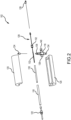
- FIG. 2 is an exploded perspective view of the vaporizer 102 of the vaporizer system 100 (shown in FIG. 1 ).
- the vaporizer 102 includes the gas manifold 116, the outer chamber 118, the heater 120, the filter 122, the thermocouples 124, 126, and the movement mechanism 128.
- the vaporizer 102 includes an inner chamber 130 that is disposed at least partially within the outer chamber 118 and spaced apart therefrom.
- both the outer chamber 118 and the inner chamber 130 are substantially tube-shaped components, and thus, the outer tube 118 has a diameter that is greater than a diameter of the inner tube 130 and both tubes are substantially concentric with one another.
- An elongate boat 132 is disposed at least partially within the inner chamber 130 and is configured to hold the charge of molten material and allow the heated inert gas to pass above the surface of the molten material.
- the boat 132 is an open container, and in some examples, can be a crucible as required or desired.
- the heater 120 at least partially surrounds the boat 132 so as to induce vaporization of the molten material.
- the boat 132 is coupled to the movement mechanism 128 so that the boat 132 can extend and retract relative to the inner chamber 130 while still being housed within the outer chamber 118.
- the inner chamber 130 acts as a guide tube and cover for the boat 132 in the vaporizer 102.
- the gas manifold 116 can be a four-way connector such as a union cross fitting.
- One opening can include a reducer fitting 134 so that the manifold 116 can be coupled in flow communication with the gas supplier 104 (shown in FIG. 1 ).
- the opposite opening can also include a reducer fitting 136 that is configured to support the gas thermocouple 124 and enable the thermocouple 124 to measure the temperature of the heated inert gas that flows though the manifold 116.
- One end of the outer chamber 118 can be coupled to another opening 138 so that the flow of heated gas can be channeled into the outer chamber 118.
- the opposite opening can include a fitting 140 that is used to support the inner chamber 130 that extends through the manifold 116.
- the fitting 140 can be a bore-through fitting that allows the inner chamber 130 to slide through.
- the movement mechanism 128 includes a reducing union fitting 152 that connects to a nut on the back end of the inner chamber 130 and swages to the movement mechanism 128.
- the fitting 152 can be used to allow the boat 132 to be completely removed from within the inner chamber 130. It should be appreciated that other orientations and layouts of the components of the manifold 116 can be used as required or desired.
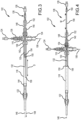
- FIG. 3 is a cross-sectional view of the vaporizer 102 in an extended position. Certain components are described above, and thus, are not necessarily described further. Additionally, the heater 120 (shown in FIGS. 1 and 2 ) is not illustrated for clarity.
- the outer chamber 118 has an inlet 142 and an opposite outlet 144 with a longitudinal axis 146 defined therebetween.
- the inlet 142 is coupled to the opening 138 of the gas manifold 116 so that the heated inert gas can flow therethrough.
- the inner chamber 130 has a first end 148 and an opposite second end 150, and extends along the longitudinal axis 146.
- the first end 148 of the inner chamber 130 is supported at one or more locations proximate the fitting 140 that is opposite of the opening 138 of the gas manifold 116 and which receives the outer chamber 118.
- the inner chamber 130 cantilevers through the gas manifold 116 via the fitting 140 and extends partially into the outer chamber 118 to generate the cantilevered second end 150.
- the reducer fitting 152 is positioned adjacent to the fitting 140 and at the first end 148 of the inner chamber 130.
- the second end 150 of the inner chamber 130 is disposed within the outer chamber 118 and closer to the inlet 142.
- the reducer fitting 152 forms a seal to the interior of the vaporizer 100 and allows the movement mechanism 128 to extend within the inner chamber 130 and couple to the elongated boat 132.
- the reducer fitting 152 includes a Teflon ferrule that allows the movement mechanism 128 to slide relative thereto.
- the fitting 140 also forms a seal around the inner chamber 130 at the gas manifold 116 so that the inner chamber 130 can extend out therefrom.
- the elongate boat 132 is slidably disposed within the inner chamber 130 and proximate the second end 150.
- the boat 132 has a proximal end 154 that couples to the movement mechanism 128 and an opposite distal end 156 that is configured to extend and retract relative to the second end 150 of the inner chamber 130 and along the longitudinal axis 146.
- the boat 132 is in its fully extended position. In the extended position, the boat 132 is still disposed completely within the outer chamber 118 and the distal end 156 extends a distance D from the second end 150 of the inner chamber 130. While a fully extended position of the distal end 156 is illustrated in FIG. 3 , it should be appreciated that the distal end 156 can extend to any position that is less than the fully extended position via the movement mechanism 128 as required or desired.
- the flow of heated inert gas 106 is channeled into the outer chamber 118 from the gas manifold 116 and towards the outlet 144. More specifically, the inert gas 106 is channeled into the annular space between the inner chamber 130 and the outer chamber 118 at the inlet 142 of the outer chamber 118. The inert gas 106 can then travel through this annular space until the second end 150 of the inner chamber 130, when the gas can pass over the boat 132 and the molten material disposed therein. The flow of inert gas mixes with the vapor emitted from the molten material to generate the mixture 108 that is expelled from the outlet 144 of the outer chamber 118 and used for calibration measurements.
- the distance D that the boat 132 extends from the inner chamber 130 defines the surface area of the molten material that produces vapor which mixes with the inert gas as it passes over.
- the surface area of the molten material is easily adjustable within the vaporizer 102 so that the vapor concentration within the emitted mixture 108 is easily controllable.
- this movement of the boat 132 allows for the heater to maintain a temperature of the molten material that produces stable vaporization (e.g., reducing oxide layers from forming on the material), while still enabling the vapor concentration in the mixture 108 to be controllable as required or desired.
- FIG. 4 is a cross-sectional view of the vaporizer 102 in a retracted position. Certain components are described above, and thus, are not necessarily described further. Additionally, the heater 120 (shown in FIGS. 1 and 2 ) is not illustrated for clarity. In the fully retracted position, the flow of heated inert gas 106 can still be channeled through the vaporizer 102 as described above, however, the boat 132 is retracted so that the distal end 156 is positioned adjacent to the second end 150 of the inner chamber 130 and the molten material is fully disposed within the inner chamber 130. This position of the boat 132 shields the molten material from the heated inert gas 106 so that the inert gas no longer directly passes over the molten material and the vapor is reduced or prevented from mixing with the gas.
- FIG. 3 a fully extended ( FIG. 3 ) and a fully retracted ( FIG. 4 ) position of the boat 132 is illustrated and described.
- the boat 132 can be positioned in any intermediate position as required or desired.
- the intermediate positions allow for the surface area of the molten material directly in contact with the flow of heated inert gas 106 to be adjusted and control of the vapor output that mixes with the inert gas because the gas does not directly pass over the molten material that is retracted within the inner chamber 130.
- the movement mechanism 128 can be used to position the boat 132 relative to the inner chamber 130.
- the movement mechanism 128 can include a linkage 158 that extends through the first end 148 of the inner chamber 130 via the reducer fitting 152.
- One end of the linkage 158 couples to the proximal end 154 of the boat 132 so as to drive movement of the boat 132 to a desired or required distance D (shown in FIG. 3 ).
- the other end of the linkage 158 is coupled to a coupler 160 so that linkage 158 can be attached to the actuator 129 (shown in FIG. 1 ) that drives linear movement M along the longitudinal axis 146.
- the position of the movement mechanism 128 determines the position of the boat 132.
- the coupler 160 also allows for attachment of the molten material thermocouple 126.
- the linkage 158 is an elongated tube concentric with both the chambers 118, 130 so that the junction of the thermocouple 126 can extend to the boat 132.
- FIG. 5 is a perspective view of the elongate boat 132 of the vaporizer 102 (shown in FIGS. 1-4 ).
- the inner chamber 130 is illustrated as transparent in FIG. 5 to show the boat 132 partially disposed therein.
- the boat 132 is in a partially extended (or partially retracted) position, where the distal end 156 of the boat 132 is at a distance D from the second end 150 of the inner chamber 130.
- a portion of the molten material disposed within the boat 132 is shielded within the inner chamber 130.
- the boat 132 is substantially semicircular in cross-sectional shape so that it can hold the molten material within the vaporizer and form a surface area that is exposed to the heated inert gas.
- the second end 150 of the inner chamber 130 is partially enclosed with an endcap 162 so as to further shield the molten material that is within the inner chamber 130 from the flow of heated inert gas. While the structure of the inner chamber 130 and the boat 132 restricts vapor from within the inner chamber 130 from mixing with the inert gas outside of the inner chamber 130, the endcap 162 does not fully seal the second end 150 of the inner chamber 130 and at least a portion of the inert gas and/or the vapor can pass through the second end 150.
- the endcap 162 can be a semicircle shape, and as such, the endcap 162 can also be used to prevent the boat 132 from rotating about the longitudinal axis (e.g., the sidewalls of the boat 132 engaging with the endcap 162) during operation. Additionally, the junction of the thermocouple 126 extends through the proximate end 154 of the boat 132 so as to be able to measure the molten material contained within. The thermocouple 126 is disposed at the bottom of the boat 132 and during operation can covered by the molten material. As such, a sheathed thermocouple 126 can be used so that the thermocouple wires and junction are protected from the liquid metal.
- the inner chamber 130 has at least one aperture 164 defined therein.
- the aperture 164 is defined between the ends of the inner chamber 130.
- the aperture 164 is located on the inner chamber 130 so that the aperture 164 is positioned proximate the fitting 140 on the gas manifold 116 (shown in FIG. 2 ) when the vaporizer is assembled. This position enables for a portion of the heated inert gas to flow through the inner chamber 130 and expelled from the second end 150.
- the gas flow through the inner chamber 130 is less than the gas flow through the outer chamber, and is used to reduce or prevent the vapor from the molten material condensing at the first end 148 of the inner chamber 130 (shown in FIG. 3 ).
- the first end of the inner chamber 130 may not be disposed within the heater 120 (shown in FIG. 1 ).
- the boat 132 when the boat 132 is in its fully retracted position (shown in FIG. 4 ), at least a portion of the boat 132 may cover the aperture 164 so as to reduce the flow of heated inert gas through the inner chamber 130.
- the temperature of the molten material may decrease when the boat 132 is in a retracted position. This temperature change of the molten material may increase aerosol formation, however, the calibration curve can still be determined and any aerosols that are produced can be removed at the filter.
- the heater may be configured to maintain the temperature of molten material at any position of the boat 132 (e.g., when the heater also surrounds at least a portion of the gas manifold) such that the vapor output is controlled at a constant temperature and aerosol formation is reduced or prevented.
- the position of the boat 132 relative to the inner chamber 130 defines the surface area of the molten material exposed to the flow of heated inert gas, and thus, the vapor output of the vaporizer.
- reducing the surface area of the molten material lowers the vapor output of the vaporizer, while increasing the surface area of the molten material raises the vapor output of the vaporizer.
- the boat 132 can remain stationary while the inner chamber 130 can move relative to the boat 132 and adjust the surface area of the molten material exposed to the flow of heated inert gas.
- the vaporizer described herein can be used to vaporize any type molten material as required or desired.
- the molten material may be an alkali metal, such as sodium.
- other alkali metals such as cesium, or a mixture of sodium and cesium that can be placed into the vaporizer.
- potassium or rubidium may be vaporized.
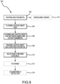
- FIG. 6 is a flowchart illustrating an exemplary method 200 for vaporizing a molten metal.
- the method 200 begins with a charge of molten metal held within a crucible being heated to generate a vapor output (operation 202).
- the crucible being disposed at least partially within an inner chamber.
- heated inert gas is flowed into an inlet of an outer chamber (operation 204).
- the inlet chamber being at least partially disposed within the outer chamber.
- the flow of heated inert gas is then channeled between the inner chamber and the outer chamber (operation 206). Downstream of the inner chamber, the flow of heated inert gas is passed over a surface area of the molten metal contained within the crucible (operation 208).
- the crucible can be selectively moved relative to the inner chamber (operation 210) so as to adjust the surface area of the molten metal exposed to the flow of heated inert gas and change the vapor output of the molten metal.
- the method 200 may further include filtering the mixture of vapor output and heated inert gas (operation 212) to remove entrained droplets or aerosols.
- the heating operation (operation 202) may further include heading the molten metal such that oxides within the molten metal are dissolved (operation 214).
- the molten metal and the inert gas can be heated to approximately an equal temperature so as to reduce aerosol formation.
- the molten metal in the method 200 may be sodium.
- the method 200 can further include calibrating a sodium ionization detector via the vapor output (operation 216).
- the crucible prior to vaporizing the molten metal, the crucible may be actively wetted. Otherwise the molten metal may have a tendency to bead up and stay off of non-wetted sections such that the molten metal does not spread evenly within the crucible.
- a strip of metal e.g., sodium
- the molten metal can then be mechanically agitated so that the crucible is wetted at all locations.
- the heat generated for this initial wetting may be from the clamshell heater.
- a separate localized heater may be used for the initial wetting, and then the crucible is placed into the vaporizer.
Landscapes
- Chemical & Material Sciences (AREA)
- Engineering & Computer Science (AREA)
- Chemical Kinetics & Catalysis (AREA)
- Physics & Mathematics (AREA)
- General Engineering & Computer Science (AREA)
- High Energy & Nuclear Physics (AREA)
- Plasma & Fusion (AREA)
- Mechanical Engineering (AREA)
- Organic Chemistry (AREA)
- Metallurgy (AREA)
- Materials Engineering (AREA)
- Life Sciences & Earth Sciences (AREA)
- General Physics & Mathematics (AREA)
- General Health & Medical Sciences (AREA)
- Biochemistry (AREA)
- Analytical Chemistry (AREA)
- Immunology (AREA)
- Pathology (AREA)
- Health & Medical Sciences (AREA)
- Electrochemistry (AREA)
- Feeding, Discharge, Calcimining, Fusing, And Gas-Generation Devices (AREA)
- Other Investigation Or Analysis Of Materials By Electrical Means (AREA)
- Sampling And Sample Adjustment (AREA)
- Monitoring And Testing Of Nuclear Reactors (AREA)
Claims (15)
- Verdampfer (102), umfassend:eine äußere Kammer (118) mit einem Einlass (142) und einem Auslass (144), wobei zwischen dem Einlass und dem Auslass eine Längsachse (146) definiert ist;eine innere Kammer (130), die wenigstens teilweise innerhalb der äußeren Kammer angeordnet ist, wobei die innere Kammer ein Ende (148) aufweist, das nahe dem Einlass der äußeren Kammer angeordnet ist;ein längliches Schiffchen (132), das wenigstens teilweise innerhalb der inneren Kammer angeordnet ist, wobei das längliche Schiffchen ein distales Ende (156) aufweist, das dazu ausgestaltet ist, bezogen auf das Ende der inneren Kammer und entlang der Längsachse zwischen wenigstens einer ausgefahrenen Position und einer vollständig eingefahrenen Position aus- und einzufahren, wobei das längliche Schiffchen dazu ausgestaltet ist, in der vollständig eingefahrenen Position zu erlauben, dass eine Teilmenge von erhitztem Gas in die innere Kammer gelangt, und wobei verhindert wird, dass das längliche Schiffchen sich um die Längsachse dreht; undeine Heizeinrichtung (120), die das längliche Schiffchen wenigstens teilweise umgibt.
- Verdampfer nach Anspruch 1, wobei:die äußere Kammer ein äußeres Rohr ist, das dazu ausgestaltet ist, einen Strom des erhitzten Gases zu empfangen; die innere Kammer ein inneres Rohr ist, das von dem äußeren Rohr beabstandet ist, sodass der Strom von erhitztem Gas durch einen ringförmigen Raum zwischen beiden hindurch kanalisiert wird;das längliche Schiffchen ein Tiegel ist, der dazu ausgestaltet ist, ein geschmolzenes Metall zu enthalten, sodass eine Oberfläche des geschmolzenen Metalls, die dem Strom von erhitztem Gas ausgesetzt ist, basierend auf der Position des Tiegels bezogen auf das innere Rohr anpassbar ist; unddie Heizeinrichtung dazu ausgestaltet ist, das geschmolzene Material zu verdampfen, wobei der Dampf sich mit dem Strom von erhitztem Gas vermischt.
- Verdampfer nach Anspruch 2, wobei, wenn der Tiegel in das innere Rohr eingefahren ist, das geschmolzene Metall dem Strom von erhitztem Gas nicht direkt ausgesetzt ist.
- Verdampfer nach einem der Ansprüche 2-3, wobei die Heizeinrichtung eine zweischalige Heizeinrichtung umfasst, die das äußere Rohr wenigstens teilweise umschließt.
- Verdampfer nach einem der Ansprüche 2-4, der ferner - dem äußeren Rohr nachgeschaltet - einen gesinterten Metallfilter (122) umfasst, der dazu ausgestaltet ist, mitgerissene Tröpfchen oder Aerosole in dem Gemisch aus Dampf und erhitztem Gas zu entfernen.
- Verdampfer nach einem der Ansprüche 2-5, der ferner einen Bewegungsmechanismus (128) umfasst, der dazu ausgestaltet ist, die Position des Tiegels bezogen auf das innere Rohr zu steuern.
- Verdampfer nach Anspruch 6, wobei der Bewegungsmechanismus ein Thermoelement (126) umfasst, das dazu ausgestaltet ist, die Temperatur des geschmolzenen Metalls zu messen.
- Verdampfer nach einem der Ansprüche 2-7, der ferner ein Thermoelement (124) umfasst, das dem äußeren Rohr vorgeschaltet angeordnet und dazu ausgestaltet ist, die Temperatur des Stroms von erhitztem Gas zu messen.
- Verdampfer nach Anspruch 1, wobei die äußere Kammer ein äußeres Rohr umfasst und die innere Kammer ein inneres Rohr umfasst und wobei das innere Rohr mit dem äußeren Rohr konzentrisch ist.
- Verdampfer nach einem der Ansprüche 1 oder 9, der ferner einen Filter (122) umfasst, der mit dem Auslass der äußeren Kammer gekoppelt ist, und wobei der Filter wenigstens teilweise innerhalb der Heizeinrichtung angeordnet ist.
- Verdampfer nach einem der Ansprüche 1 oder 9-10, der ferner einen Bewegungsmechanismus (128) umfasst, der mit einem proximalen Ende des länglichen Schiffchens gekoppelt ist.
- Verdampfer nach Anspruch 11, wobei der Bewegungsmechanismus sich wenigstens teilweise durch ein zweites Ende der inneren Kammer hindurch erstreckt.
- Verdampfer nach einem der Ansprüche 1 oder 9-12, wobei das Ende des inneren Kanals wenigstens teilweise umschlossen ist.
- Verdampfer nach einem der Ansprüche 1 oder 9-13, der ferner einen Gasverteiler (116) umfasst, der mit dem Einlass der äußeren Kammer gekoppelt ist.
- Verfahren (200) zum Verdampfen von geschmolzenem Metall, umfassend:Erhitzen (202) einer Charge von geschmolzenem Metall, die in einem Tiegel (132) enthalten ist, um eine Dampf-Abgabe zu bewirken, wobei der Tiegel wenigstens teilweise innerhalb einer inneren Kammer (130) angeordnet ist;Leiten (204) von erhitztem Inertgas in einen Einlass (142) einer äußeren Kammer (118), wobei die innere Kammer wenigstens teilweise innerhalb der äußeren Kammer angeordnet ist;Kanalisieren (206) des Stroms von erhitztem Inertgas zwischen der inneren Kammer und der äußeren Kammer;Passierenlassen (208) des Stroms von erhitztem Inertgas über eine Oberfläche des geschmolzenen Metalls, wobei beim Passieren des erhitzten Inertgases über die Oberfläche wenigstens eine Teilmenge des abgegebenen Dampfes sich damit vermischt; undselektives Bewegen (210) des Tiegels bezogen auf die innere Kammer, um die Oberfläche des geschmolzenen Metalls, die dem Strom von erhitztem Inertgas ausgesetzt ist, anzupassen und die Dampf-Abgabe des geschmolzenen Materials zu ändern, wobei der Tiegel ein distales Ende (156) aufweist, das dazu ausgestaltet ist, bezogen auf das Ende der inneren Kammer und entlang der Längsachse zwischen wenigstens einer ausgefahrenen Position und einer vollständig eingefahrenen Position aus- und einzufahren, wobei der Tiegel dazu ausgestaltet ist, in der vollständig eingefahrenen Position zu erlauben, dass eine Teilmenge von erhitztem Gas in die innere Kammer gelangt, und wobei verhindert wird, dass der Tiegel sich um die Längsachse dreht.
Applications Claiming Priority (2)
| Application Number | Priority Date | Filing Date | Title |
|---|---|---|---|
| US201962891244P | 2019-08-23 | 2019-08-23 | |
| PCT/US2020/042905 WO2021040911A1 (en) | 2019-08-23 | 2020-07-21 | Sodium vaporizer and method for use of sodium vaporizer |
Publications (2)
| Publication Number | Publication Date |
|---|---|
| EP4018014A1 EP4018014A1 (de) | 2022-06-29 |
| EP4018014B1 true EP4018014B1 (de) | 2024-12-18 |
Family
ID=71995158
Family Applications (1)
| Application Number | Title | Priority Date | Filing Date |
|---|---|---|---|
| EP20753621.0A Active EP4018014B1 (de) | 2019-08-23 | 2020-07-21 | Natriumverdampfer und anwendungsverfahren eines natriumverdampfers |
Country Status (6)
| Country | Link |
|---|---|
| US (2) | US11626213B2 (de) |
| EP (1) | EP4018014B1 (de) |
| JP (1) | JP7559048B2 (de) |
| KR (1) | KR102910316B1 (de) |
| CA (1) | CA3143290A1 (de) |
| WO (1) | WO2021040911A1 (de) |
Families Citing this family (4)
| Publication number | Priority date | Publication date | Assignee | Title |
|---|---|---|---|---|
| EP4018014B1 (de) * | 2019-08-23 | 2024-12-18 | TerraPower, LLC | Natriumverdampfer und anwendungsverfahren eines natriumverdampfers |
| US12431253B2 (en) | 2023-06-21 | 2025-09-30 | Abilene Christian University | Fission product extraction system and methods of use thereof |
| WO2025034739A2 (en) | 2023-08-07 | 2025-02-13 | Abilene Christian University | A method calibrating power monitors for molten salt reactors at low power |
| CN119468701B (zh) * | 2025-01-15 | 2025-04-04 | 山西金祥冶金炉料有限公司 | 一种金属冶炼用合金添加装置及添加方法 |
Family Cites Families (77)
| Publication number | Priority date | Publication date | Assignee | Title |
|---|---|---|---|---|
| GB1141083A (en) | 1965-06-28 | 1969-01-22 | North American Aviation Inc | Method of converting thermal energy directly to electrical energy |
| JPS5015204B1 (de) | 1970-05-29 | 1975-06-03 | ||
| NL172604C (nl) | 1970-07-23 | 1983-09-16 | Interatom | Inrichting voor het continu afscheiden van metaaldampen of metaalaerosolen in vloeibare vorm uit gassen, in het bijzonder van natriumdamp of -druppeltjes uit het schutgas van een natriumgekoelde kernenergie-installatie. |
| US3993453A (en) | 1973-05-09 | 1976-11-23 | General Electric Company | Getter for nuclear fuel elements |
| US4117396A (en) | 1974-01-21 | 1978-09-26 | Westinghouse Electric Corp. | Sensor for thermally ionizable particles and/or vapors |
| JPS51107212A (de) | 1975-03-19 | 1976-09-22 | Tokyo Shibaura Electric Co | |
| US4119488A (en) | 1975-04-10 | 1978-10-10 | S.A.E.S. Getters S.P.A. | Nuclear reactor fuel element employing Zr2 Ni as a getter metal |
| JPS5814494B2 (ja) | 1975-05-30 | 1983-03-19 | 三菱重工業株式会社 | エキタイチユウノイブツホシユウソウチ |
| US4047101A (en) | 1976-01-08 | 1977-09-06 | Westinghouse Electric Corporation | Filament for alkali metal ionization detector |
| US4095171A (en) | 1976-04-07 | 1978-06-13 | Westinghouse Electric Corp. | Alkali metal ionization detector |
| US4047040A (en) | 1976-05-06 | 1977-09-06 | General Electric Company | Gridded ionization chamber |
| US4131511A (en) | 1977-02-04 | 1978-12-26 | Combustion Engineering, Inc. | Nuclear fuel element |
| US4121458A (en) | 1977-02-24 | 1978-10-24 | Westinghouse Electric Corp. | Reliable dynamoelectric machine condition monitor |
| NL7802116A (nl) * | 1977-03-14 | 1978-09-18 | Getters Spa | Alkalimetaaldampgenerator. |
| SU693868A1 (ru) | 1977-08-01 | 1984-08-07 | Институт Физики Ан Латвсср | Способ непрерывной очистки жидкометаллического расплава в контуре циркул ции |
| DE2746159A1 (de) | 1977-10-14 | 1979-04-19 | Interatom | Kernenergieanlage mit einrichtung zur kuehlmittelreinigung |
| US4257847A (en) | 1978-10-06 | 1981-03-24 | The United States Of America As Represented By The United States Department Of Energy | Nuclear breeder reactor fuel element with axial tandem stacking and getter |
| FR2438840A1 (fr) | 1978-10-11 | 1980-05-09 | Hitachi Ltd | Detecteur d'ionisation du sodium |
| US4325029A (en) | 1979-09-10 | 1982-04-13 | Westinghouse Electric Corp. | Alkali ionization detector |
| CA1202787A (en) | 1982-01-19 | 1986-04-08 | John Z. Grens | Apparatus and method for reprocessing and separating spent nuclear fuels |
| US4853177A (en) | 1983-05-06 | 1989-08-01 | The Babcock & Wilcox Company | Void plug for annular fuel pellets |
| US4587083A (en) | 1983-08-10 | 1986-05-06 | The United States Of America As Represented By The United States Department Of Energy | Method for removing cesium from a nuclear reactor coolant |
| FR2550681B1 (fr) | 1983-08-12 | 1985-12-06 | Centre Nat Rech Scient | Source d'ions a au moins deux chambres d'ionisation, en particulier pour la formation de faisceaux d'ions chimiquement reactifs |
| JPS6043447A (ja) | 1983-08-17 | 1985-03-08 | Hitachi Ltd | 液体金属精製装置 |
| US4578242A (en) * | 1984-07-03 | 1986-03-25 | General Motors Corporation | Metallothermic reduction of rare earth oxides |
| JPS6124640U (ja) * | 1984-07-19 | 1986-02-14 | 住友金属工業株式会社 | 高温ダストのサンプリング装置 |
| JPS61228382A (ja) | 1985-04-03 | 1986-10-11 | 日本核燃料開発株式会社 | 核燃料要素 |
| US4710343A (en) | 1985-11-27 | 1987-12-01 | The United States Of America As Represented By The United States Department Of Energy | Nuclear breeder reactor fuel element with silicon carbide getter |
| US4719355A (en) | 1986-04-10 | 1988-01-12 | Texas Instruments Incorporated | Ion source for an ion implanter |
| JPS62182434U (de) * | 1986-05-09 | 1987-11-19 | ||
| US4806489A (en) * | 1987-03-06 | 1989-02-21 | Varian Associates | Matrix modifier and method for modifying a matrix to improve analysis of metal constituents during graphite furnace atomic absorption spectroscopy |
| JPH0823598B2 (ja) | 1987-11-09 | 1996-03-06 | 株式会社日立製作所 | 放射性物質除去装置 |
| US4845364A (en) | 1988-02-29 | 1989-07-04 | Battelle Memorial Institute | Coaxial reentrant ion source for surface mass spectroscopy |
| US5030411A (en) | 1988-11-14 | 1991-07-09 | Westinghouse Electric Corp. | Removal of impurities from coolant of a nuclear reactor |
| DE3908265A1 (de) * | 1989-03-14 | 1990-09-20 | Leybold Ag | Chargiervorrichtung fuer schmelzanlagen |
| JP2863939B2 (ja) | 1990-01-08 | 1999-03-03 | 株式会社日立製作所 | トリチウムの透過低減装置 |
| JPH0469592A (ja) | 1990-07-09 | 1992-03-04 | Chugoku Electric Power Co Inc:The | 核燃料要素 |
| JPH04122897A (ja) | 1990-09-14 | 1992-04-23 | Hitachi Ltd | 不純物除去装置 |
| JP2995582B2 (ja) | 1990-11-29 | 1999-12-27 | セイコーインスツルメンツ株式会社 | 液体金属イオン源 |
| JPH04286996A (ja) | 1991-03-15 | 1992-10-12 | Hitachi Ltd | 不純物除去装置 |
| EP0508715A1 (de) | 1991-04-09 | 1992-10-14 | General Electric Company | Getter enthaltendes Kernbrennelement |
| US5820681A (en) | 1995-05-03 | 1998-10-13 | Chorus Corporation | Unibody crucible and effusion cell employing such a crucible |
| JP3031858B2 (ja) | 1996-03-13 | 2000-04-10 | 核燃料サイクル開発機構 | Na中の不純物分析装置及びこれを用いたNa中の不純物分析方法 |
| US6030458A (en) * | 1997-02-14 | 2000-02-29 | Chorus Corporation | Phosphorus effusion source |
| US6117208A (en) * | 1998-04-23 | 2000-09-12 | Sharma; Ram A. | Molten salt process for producing titanium or zirconium powder |
| US6069362A (en) | 1998-05-14 | 2000-05-30 | The University Of Akron | Multi-density and multi-atomic number detector media for applications |
| US6602919B1 (en) | 1999-09-17 | 2003-08-05 | Ut-Battelle Llc | Method for preparing hydrous zirconium oxide gels and spherules |
| US6840085B1 (en) | 2001-09-18 | 2005-01-11 | Robert J. Kolaja | Photoionization detector with multiple ionization cells |
| KR20030059708A (ko) | 2002-01-04 | 2003-07-10 | 필터레이 화이버 옵틱스 인코퍼레이티드 | 세슘 공급 장치 및 방법 |
| KR20030085198A (ko) | 2002-04-29 | 2003-11-05 | 필터레이 화이버 옵틱스 인코퍼레이티드 | 세슘 공급장치 및 방법 |
| US8123862B2 (en) * | 2003-08-15 | 2012-02-28 | Semiconductor Energy Laboratory Co., Ltd. | Deposition apparatus and manufacturing apparatus |
| JP2006047232A (ja) | 2004-08-09 | 2006-02-16 | Horiba Ltd | 気体中の微量物質の定量分析方法、その定量分析装置、そのサンプリング方法およびそのサンプリング装置 |
| ITMI20041736A1 (it) * | 2004-09-10 | 2004-12-10 | Getters Spa | Miscele per l'evaporazione del litio e dispensatori di litio |
| ITMI20042279A1 (it) * | 2004-11-24 | 2005-02-24 | Getters Spa | Sistema dispensatore di metalli alcalini in grado di dispensare quantita' elevate di metalli |
| FI118803B (fi) * | 2005-04-22 | 2008-03-31 | Beneq Oy | Lähde, järjestely lähteen asentamiseksi sekä menetelmä lähteen asentamiseksi ja poistamiseksi |
| KR101071605B1 (ko) * | 2006-05-19 | 2011-10-10 | 가부시키가이샤 알박 | 유기 증착 재료용 증착 장치, 유기 박막의 제조 방법 |
| CN101168128A (zh) | 2006-10-25 | 2008-04-30 | 刘芬 | 复合金属氧化物催化剂及其制备方法和用途 |
| RU2328783C1 (ru) | 2006-12-18 | 2008-07-10 | Федеральное государственное унитарное предприятие Научно-исследовательский институт Научно-производственное объединение "Луч" | Микротвэл ядерного реактора |
| JP5376764B2 (ja) | 2007-03-19 | 2013-12-25 | フタムラ化学株式会社 | 吸油性連通多孔質構造体 |
| JP4936492B2 (ja) | 2008-03-25 | 2012-05-23 | 国立大学法人大阪大学 | 放電イオン化電流検出器 |
| KR101288610B1 (ko) | 2008-07-24 | 2013-07-22 | 주식회사 만도 | 차량용 게이트웨이 전자제어장치 및 그의 주행정보기록방법 |
| KR101658809B1 (ko) | 2009-10-30 | 2016-09-22 | 뱁콕 앤드 윌콕스 캐나다 엘티디. | 방사성 파편 포집장치 |
| US8502158B1 (en) | 2010-04-07 | 2013-08-06 | Polimaster IP Solutions LLC | Distributed system for radiation detection utilizing multiple clustered detectors |
| JP2012032250A (ja) | 2010-07-30 | 2012-02-16 | Hitachi-Ge Nuclear Energy Ltd | 高速増殖炉カバーガス系のナトリウム凝縮型除去装置 |
| US20130010915A1 (en) | 2011-07-08 | 2013-01-10 | Battelle Energy Alliance, Llc | Reactor fuel elements and related methods |
| FR2992976B1 (fr) * | 2012-07-04 | 2014-07-18 | Riber | Dispositif d'evaporation pour appareil de depot sous vide et appareil de depot sous vide comprenant un tel dispositif d'evaporation |
| JP6041433B2 (ja) | 2012-10-30 | 2016-12-07 | 有冨 正憲 | 汚染物質処理装置 |
| US9178103B2 (en) | 2013-08-09 | 2015-11-03 | Tsmc Solar Ltd. | Apparatus and method for forming chalcogenide semiconductor absorber materials with sodium impurities |
| JP6101669B2 (ja) | 2013-12-16 | 2017-03-22 | 株式会社日本自動車部品総合研究所 | ガスセンサ |
| US9302226B2 (en) | 2014-05-05 | 2016-04-05 | Ge-Hitachi Nuclear Energy Americas Llc | Salt filtration system and method of removing a radioactive material from a gas using the same |
| US9341596B1 (en) | 2014-12-22 | 2016-05-17 | International Business Machines Corporation | Annular gas ionization delta E-E detector |
| US10184168B2 (en) * | 2015-01-20 | 2019-01-22 | Kennametal Inc. | IMC evaporator boat-thermal insulation cartridge assembly |
| RU2726648C1 (ru) | 2016-03-08 | 2020-07-15 | ТерраПауэр, ЭлЭлСи | Геттер продуктов деления |
| US9921184B2 (en) | 2016-05-20 | 2018-03-20 | Terrapower, Llc | Sodium-cesium ionization detector |
| CN109074883A (zh) | 2016-05-20 | 2018-12-21 | 泰拉能源公司 | 钠-铯蒸气阱系统和方法 |
| CN207038182U (zh) | 2017-03-29 | 2018-02-23 | 泰拉能源有限责任公司 | 铯收集器 |
| EP4018014B1 (de) * | 2019-08-23 | 2024-12-18 | TerraPower, LLC | Natriumverdampfer und anwendungsverfahren eines natriumverdampfers |
-
2020
- 2020-07-21 EP EP20753621.0A patent/EP4018014B1/de active Active
- 2020-07-21 CA CA3143290A patent/CA3143290A1/en active Pending
- 2020-07-21 KR KR1020227004045A patent/KR102910316B1/ko active Active
- 2020-07-21 JP JP2022506811A patent/JP7559048B2/ja active Active
- 2020-07-21 US US16/934,901 patent/US11626213B2/en active Active
- 2020-07-21 WO PCT/US2020/042905 patent/WO2021040911A1/en not_active Ceased
-
2023
- 2023-03-21 US US18/124,159 patent/US12073951B2/en active Active
Also Published As
| Publication number | Publication date |
|---|---|
| US20210057117A1 (en) | 2021-02-25 |
| EP4018014A1 (de) | 2022-06-29 |
| JP7559048B2 (ja) | 2024-10-01 |
| US12073951B2 (en) | 2024-08-27 |
| US20230223161A1 (en) | 2023-07-13 |
| JP2022544755A (ja) | 2022-10-21 |
| KR20220051165A (ko) | 2022-04-26 |
| US11626213B2 (en) | 2023-04-11 |
| KR102910316B1 (ko) | 2026-01-08 |
| WO2021040911A1 (en) | 2021-03-04 |
| CA3143290A1 (en) | 2021-03-04 |
Similar Documents
| Publication | Publication Date | Title |
|---|---|---|
| US12073951B2 (en) | Sodium vaporizer and methods | |
| Arrowsmith et al. | Spectroscopy of the transition state. II. F+ Na2→ FNaNa‡*→ NaF+ Na | |
| DE19816348C1 (de) | Pyrolysereaktor zur Pyrolyse organischer und anorganischer Proben, Elementaranalysator enthaltend diesen Pyrolysereaktor und Verfahren zur massenspektrometrischen on-line Bestimmung der Sauerstoffisotopenzusammensetzung organischer und anorganischer Proben | |
| EP3500839B1 (de) | Anwendungsprofilreaktor für operando-messungen | |
| Buttersack et al. | Deeply cooled and temperature controlled microjets: Liquid ammonia solutions released into vacuum for analysis by photoelectron spectroscopy | |
| Ure et al. | Nomenclature, symbols, units and their usage in spectrochemical analysis-XII. Terms related to electrothermal atomization (IUPAC Recommendations 1992) | |
| CN101313207B (zh) | 用于光谱分析的方法和装置 | |
| DE4443407C2 (de) | Vorrichtung zur qualitativen und/oder quantitativen chemischen Analyse einer Substanz, insbesondere zur Analyse einer Metallschmelze | |
| US20240094133A1 (en) | Method and apparatus for quantitative chemical analysis of liquid metals and alloys | |
| US5367374A (en) | Platform for a transversely-heated electrothermal atomizer furnace for atom absorption spectroscopy | |
| EP0447747A2 (de) | Verfahren und Vorrichtung zum Einspritzen von Komponenten in Plasma zur "ICP-OES"-Analyse | |
| Alp et al. | In situ trapping of antimony hydride on iridium-coated tungsten coil and interference studies | |
| de Oliveira et al. | Selenium preconcentration in a gold “amalgamator” after hydride generation for atomic spectrometry | |
| EP2748598A1 (de) | Vorrichtung, verfahren und ausrüstung zur übertragung von analyten | |
| KR101462022B1 (ko) | 마이크로파를 이용한 시료연소분석장치 | |
| Kratzer et al. | Spectral interferences of oxygen and water molecules in hydride generation atomic absorption spectrometry with quartz atomizers: Comparison of preconcentration and on-line atomization modes for As and Se determination | |
| Imai et al. | Investigations of pyrolysed ascorbic acid in an electrothermal graphite furnace by inductively coupled argon plasma mass spectrometry and Raman spectrometry | |
| RU2839679C1 (ru) | Способ и устройство для количественного химического анализа жидких металлов и сплавов | |
| JP3040495B2 (ja) | 高周波誘導結合プラズママススペクトル分析を用いる検体の元素分析のための改良法およびこの改良法を実施するための装置 | |
| JPH0342420B2 (de) | ||
| Dutouquet et al. | LIBS for characterizing nanomaterials | |
| JPH03150449A (ja) | 原子分光計による揮発性サンプル分析装置 | |
| Nagy et al. | Thermospectrometry: A new method to follow the thermal processes with spectrometric methods | |
| WO2025074450A1 (en) | Improved method for enabling accurate measurements of high vapor pressure elements in molten metal using laser-induced breakdown spectroscopy | |
| BRPI0802679A2 (pt) | tubo para atomização, dispositivo compreendendo tubo para atomização e método para determinação de átomos |
Legal Events
| Date | Code | Title | Description |
|---|---|---|---|
| STAA | Information on the status of an ep patent application or granted ep patent |
Free format text: STATUS: UNKNOWN |
|
| STAA | Information on the status of an ep patent application or granted ep patent |
Free format text: STATUS: THE INTERNATIONAL PUBLICATION HAS BEEN MADE |
|
| PUAI | Public reference made under article 153(3) epc to a published international application that has entered the european phase |
Free format text: ORIGINAL CODE: 0009012 |
|
| STAA | Information on the status of an ep patent application or granted ep patent |
Free format text: STATUS: REQUEST FOR EXAMINATION WAS MADE |
|
| 17P | Request for examination filed |
Effective date: 20220228 |
|
| AK | Designated contracting states |
Kind code of ref document: A1 Designated state(s): AL AT BE BG CH CY CZ DE DK EE ES FI FR GB GR HR HU IE IS IT LI LT LU LV MC MK MT NL NO PL PT RO RS SE SI SK SM TR |
|
| DAV | Request for validation of the european patent (deleted) | ||
| DAX | Request for extension of the european patent (deleted) | ||
| P01 | Opt-out of the competence of the unified patent court (upc) registered |
Effective date: 20230515 |
|
| GRAP | Despatch of communication of intention to grant a patent |
Free format text: ORIGINAL CODE: EPIDOSNIGR1 |
|
| STAA | Information on the status of an ep patent application or granted ep patent |
Free format text: STATUS: GRANT OF PATENT IS INTENDED |
|
| INTG | Intention to grant announced |
Effective date: 20240726 |
|
| GRAS | Grant fee paid |
Free format text: ORIGINAL CODE: EPIDOSNIGR3 |
|
| GRAA | (expected) grant |
Free format text: ORIGINAL CODE: 0009210 |
|
| STAA | Information on the status of an ep patent application or granted ep patent |
Free format text: STATUS: THE PATENT HAS BEEN GRANTED |
|
| AK | Designated contracting states |
Kind code of ref document: B1 Designated state(s): AL AT BE BG CH CY CZ DE DK EE ES FI FR GB GR HR HU IE IS IT LI LT LU LV MC MK MT NL NO PL PT RO RS SE SI SK SM TR |
|
| REG | Reference to a national code |
Ref country code: CH Ref legal event code: EP |
|
| REG | Reference to a national code |
Ref country code: DE Ref legal event code: R096 Ref document number: 602020043371 Country of ref document: DE |
|
| REG | Reference to a national code |
Ref country code: IE Ref legal event code: FG4D |
|
| REG | Reference to a national code |
Ref country code: LT Ref legal event code: MG9D |
|
| PG25 | Lapsed in a contracting state [announced via postgrant information from national office to epo] |
Ref country code: HR Free format text: LAPSE BECAUSE OF FAILURE TO SUBMIT A TRANSLATION OF THE DESCRIPTION OR TO PAY THE FEE WITHIN THE PRESCRIBED TIME-LIMIT Effective date: 20241218 |
|
| PG25 | Lapsed in a contracting state [announced via postgrant information from national office to epo] |
Ref country code: FI Free format text: LAPSE BECAUSE OF FAILURE TO SUBMIT A TRANSLATION OF THE DESCRIPTION OR TO PAY THE FEE WITHIN THE PRESCRIBED TIME-LIMIT Effective date: 20241218 |
|
| PG25 | Lapsed in a contracting state [announced via postgrant information from national office to epo] |
Ref country code: BG Free format text: LAPSE BECAUSE OF FAILURE TO SUBMIT A TRANSLATION OF THE DESCRIPTION OR TO PAY THE FEE WITHIN THE PRESCRIBED TIME-LIMIT Effective date: 20241218 |
|
| PG25 | Lapsed in a contracting state [announced via postgrant information from national office to epo] |
Ref country code: NO Free format text: LAPSE BECAUSE OF FAILURE TO SUBMIT A TRANSLATION OF THE DESCRIPTION OR TO PAY THE FEE WITHIN THE PRESCRIBED TIME-LIMIT Effective date: 20250318 |
|
| REG | Reference to a national code |
Ref country code: NL Ref legal event code: MP Effective date: 20241218 |
|
| PG25 | Lapsed in a contracting state [announced via postgrant information from national office to epo] |
Ref country code: LV Free format text: LAPSE BECAUSE OF FAILURE TO SUBMIT A TRANSLATION OF THE DESCRIPTION OR TO PAY THE FEE WITHIN THE PRESCRIBED TIME-LIMIT Effective date: 20241218 Ref country code: GR Free format text: LAPSE BECAUSE OF FAILURE TO SUBMIT A TRANSLATION OF THE DESCRIPTION OR TO PAY THE FEE WITHIN THE PRESCRIBED TIME-LIMIT Effective date: 20250319 |
|
| PG25 | Lapsed in a contracting state [announced via postgrant information from national office to epo] |
Ref country code: RS Free format text: LAPSE BECAUSE OF FAILURE TO SUBMIT A TRANSLATION OF THE DESCRIPTION OR TO PAY THE FEE WITHIN THE PRESCRIBED TIME-LIMIT Effective date: 20250318 |
|
| PG25 | Lapsed in a contracting state [announced via postgrant information from national office to epo] |
Ref country code: NL Free format text: LAPSE BECAUSE OF FAILURE TO SUBMIT A TRANSLATION OF THE DESCRIPTION OR TO PAY THE FEE WITHIN THE PRESCRIBED TIME-LIMIT Effective date: 20241218 |
|
| REG | Reference to a national code |
Ref country code: AT Ref legal event code: MK05 Ref document number: 1752301 Country of ref document: AT Kind code of ref document: T Effective date: 20241218 |
|
| PG25 | Lapsed in a contracting state [announced via postgrant information from national office to epo] |
Ref country code: SM Free format text: LAPSE BECAUSE OF FAILURE TO SUBMIT A TRANSLATION OF THE DESCRIPTION OR TO PAY THE FEE WITHIN THE PRESCRIBED TIME-LIMIT Effective date: 20241218 |
|
| PG25 | Lapsed in a contracting state [announced via postgrant information from national office to epo] |
Ref country code: PL Free format text: LAPSE BECAUSE OF FAILURE TO SUBMIT A TRANSLATION OF THE DESCRIPTION OR TO PAY THE FEE WITHIN THE PRESCRIBED TIME-LIMIT Effective date: 20241218 |
|
| PG25 | Lapsed in a contracting state [announced via postgrant information from national office to epo] |
Ref country code: ES Free format text: LAPSE BECAUSE OF FAILURE TO SUBMIT A TRANSLATION OF THE DESCRIPTION OR TO PAY THE FEE WITHIN THE PRESCRIBED TIME-LIMIT Effective date: 20241218 |
|
| PGFP | Annual fee paid to national office [announced via postgrant information from national office to epo] |
Ref country code: GB Payment date: 20250619 Year of fee payment: 6 |
|
| PG25 | Lapsed in a contracting state [announced via postgrant information from national office to epo] |
Ref country code: IS Free format text: LAPSE BECAUSE OF FAILURE TO SUBMIT A TRANSLATION OF THE DESCRIPTION OR TO PAY THE FEE WITHIN THE PRESCRIBED TIME-LIMIT Effective date: 20250418 |
|
| PG25 | Lapsed in a contracting state [announced via postgrant information from national office to epo] |
Ref country code: PT Free format text: LAPSE BECAUSE OF FAILURE TO SUBMIT A TRANSLATION OF THE DESCRIPTION OR TO PAY THE FEE WITHIN THE PRESCRIBED TIME-LIMIT Effective date: 20250421 |
|
| PG25 | Lapsed in a contracting state [announced via postgrant information from national office to epo] |
Ref country code: EE Free format text: LAPSE BECAUSE OF FAILURE TO SUBMIT A TRANSLATION OF THE DESCRIPTION OR TO PAY THE FEE WITHIN THE PRESCRIBED TIME-LIMIT Effective date: 20241218 |
|
| PGFP | Annual fee paid to national office [announced via postgrant information from national office to epo] |
Ref country code: FR Payment date: 20250620 Year of fee payment: 6 |
|
| PG25 | Lapsed in a contracting state [announced via postgrant information from national office to epo] |
Ref country code: AT Free format text: LAPSE BECAUSE OF FAILURE TO SUBMIT A TRANSLATION OF THE DESCRIPTION OR TO PAY THE FEE WITHIN THE PRESCRIBED TIME-LIMIT Effective date: 20241218 Ref country code: RO Free format text: LAPSE BECAUSE OF FAILURE TO SUBMIT A TRANSLATION OF THE DESCRIPTION OR TO PAY THE FEE WITHIN THE PRESCRIBED TIME-LIMIT Effective date: 20241218 |
|
| PG25 | Lapsed in a contracting state [announced via postgrant information from national office to epo] |
Ref country code: SK Free format text: LAPSE BECAUSE OF FAILURE TO SUBMIT A TRANSLATION OF THE DESCRIPTION OR TO PAY THE FEE WITHIN THE PRESCRIBED TIME-LIMIT Effective date: 20241218 |
|
| PG25 | Lapsed in a contracting state [announced via postgrant information from national office to epo] |
Ref country code: CZ Free format text: LAPSE BECAUSE OF FAILURE TO SUBMIT A TRANSLATION OF THE DESCRIPTION OR TO PAY THE FEE WITHIN THE PRESCRIBED TIME-LIMIT Effective date: 20241218 |
|
| PG25 | Lapsed in a contracting state [announced via postgrant information from national office to epo] |
Ref country code: IT Free format text: LAPSE BECAUSE OF FAILURE TO SUBMIT A TRANSLATION OF THE DESCRIPTION OR TO PAY THE FEE WITHIN THE PRESCRIBED TIME-LIMIT Effective date: 20241218 |
|
| PG25 | Lapsed in a contracting state [announced via postgrant information from national office to epo] |
Ref country code: SE Free format text: LAPSE BECAUSE OF FAILURE TO SUBMIT A TRANSLATION OF THE DESCRIPTION OR TO PAY THE FEE WITHIN THE PRESCRIBED TIME-LIMIT Effective date: 20241218 |
|
| REG | Reference to a national code |
Ref country code: DE Ref legal event code: R097 Ref document number: 602020043371 Country of ref document: DE |
|
| PG25 | Lapsed in a contracting state [announced via postgrant information from national office to epo] |
Ref country code: DK Free format text: LAPSE BECAUSE OF FAILURE TO SUBMIT A TRANSLATION OF THE DESCRIPTION OR TO PAY THE FEE WITHIN THE PRESCRIBED TIME-LIMIT Effective date: 20241218 |
|
| PGFP | Annual fee paid to national office [announced via postgrant information from national office to epo] |
Ref country code: DE Payment date: 20250620 Year of fee payment: 6 |
|
| PLBE | No opposition filed within time limit |
Free format text: ORIGINAL CODE: 0009261 |
|
| STAA | Information on the status of an ep patent application or granted ep patent |
Free format text: STATUS: NO OPPOSITION FILED WITHIN TIME LIMIT |
|
| 26N | No opposition filed |
Effective date: 20250919 |