EP3929664B1 - Prozesskartusche und vorrichtung zur formung elektrofotografischer bilder - Google Patents
Prozesskartusche und vorrichtung zur formung elektrofotografischer bilder Download PDFInfo
- Publication number
- EP3929664B1 EP3929664B1 EP21186006.9A EP21186006A EP3929664B1 EP 3929664 B1 EP3929664 B1 EP 3929664B1 EP 21186006 A EP21186006 A EP 21186006A EP 3929664 B1 EP3929664 B1 EP 3929664B1
- Authority
- EP
- European Patent Office
- Prior art keywords
- drum
- coupling
- process cartridge
- gear
- gear portion
- Prior art date
- Legal status (The legal status is an assumption and is not a legal conclusion. Google has not performed a legal analysis and makes no representation as to the accuracy of the status listed.)
- Active
Links
- 238000000034 method Methods 0.000 title claims description 90
- 230000008569 process Effects 0.000 title claims description 90
- 230000008878 coupling Effects 0.000 claims description 508
- 238000010168 coupling process Methods 0.000 claims description 505
- 238000005859 coupling reaction Methods 0.000 claims description 505
- 230000001105 regulatory effect Effects 0.000 claims description 152
- 230000033001 locomotion Effects 0.000 claims description 24
- 230000002093 peripheral effect Effects 0.000 claims description 23
- 238000011144 upstream manufacturing Methods 0.000 claims description 15
- 238000011161 development Methods 0.000 claims description 11
- 230000005540 biological transmission Effects 0.000 description 270
- 238000004140 cleaning Methods 0.000 description 44
- 239000000463 material Substances 0.000 description 16
- 238000012546 transfer Methods 0.000 description 11
- 238000013459 approach Methods 0.000 description 9
- 230000002829 reductive effect Effects 0.000 description 9
- 230000000052 comparative effect Effects 0.000 description 8
- 230000018109 developmental process Effects 0.000 description 7
- 230000007246 mechanism Effects 0.000 description 6
- 238000003825 pressing Methods 0.000 description 6
- 230000009471 action Effects 0.000 description 4
- 230000033228 biological regulation Effects 0.000 description 4
- 239000000470 constituent Substances 0.000 description 4
- 230000005484 gravity Effects 0.000 description 4
- 230000004048 modification Effects 0.000 description 4
- 238000012986 modification Methods 0.000 description 4
- 238000003756 stirring Methods 0.000 description 4
- 239000002699 waste material Substances 0.000 description 4
- 238000012423 maintenance Methods 0.000 description 3
- 230000015572 biosynthetic process Effects 0.000 description 2
- 238000006243 chemical reaction Methods 0.000 description 2
- 239000003795 chemical substances by application Substances 0.000 description 2
- 230000006835 compression Effects 0.000 description 2
- 238000007906 compression Methods 0.000 description 2
- 230000007423 decrease Effects 0.000 description 2
- 230000000694 effects Effects 0.000 description 2
- 238000010438 heat treatment Methods 0.000 description 2
- 230000002452 interceptive effect Effects 0.000 description 2
- 101100042630 Caenorhabditis elegans sin-3 gene Proteins 0.000 description 1
- 238000005452 bending Methods 0.000 description 1
- 230000008901 benefit Effects 0.000 description 1
- 238000007664 blowing Methods 0.000 description 1
- 230000003247 decreasing effect Effects 0.000 description 1
- 230000001419 dependent effect Effects 0.000 description 1
- 238000010586 diagram Methods 0.000 description 1
- 239000013013 elastic material Substances 0.000 description 1
- 230000000670 limiting effect Effects 0.000 description 1
- 239000002985 plastic film Substances 0.000 description 1
- 230000002265 prevention Effects 0.000 description 1
- -1 recording sheet Substances 0.000 description 1
- 230000002441 reversible effect Effects 0.000 description 1
Images


Classifications
-
- G—PHYSICS
- G03—PHOTOGRAPHY; CINEMATOGRAPHY; ANALOGOUS TECHNIQUES USING WAVES OTHER THAN OPTICAL WAVES; ELECTROGRAPHY; HOLOGRAPHY
- G03G—ELECTROGRAPHY; ELECTROPHOTOGRAPHY; MAGNETOGRAPHY
- G03G21/00—Arrangements not provided for by groups G03G13/00 - G03G19/00, e.g. cleaning, elimination of residual charge
- G03G21/16—Mechanical means for facilitating the maintenance of the apparatus, e.g. modular arrangements
- G03G21/18—Mechanical means for facilitating the maintenance of the apparatus, e.g. modular arrangements using a processing cartridge, whereby the process cartridge comprises at least two image processing means in a single unit
- G03G21/1839—Means for handling the process cartridge in the apparatus body
- G03G21/1857—Means for handling the process cartridge in the apparatus body for transmitting mechanical drive power to the process cartridge, drive mechanisms, gears, couplings, braking mechanisms
- G03G21/186—Axial couplings
-
- G—PHYSICS
- G03—PHOTOGRAPHY; CINEMATOGRAPHY; ANALOGOUS TECHNIQUES USING WAVES OTHER THAN OPTICAL WAVES; ELECTROGRAPHY; HOLOGRAPHY
- G03G—ELECTROGRAPHY; ELECTROPHOTOGRAPHY; MAGNETOGRAPHY
- G03G15/00—Apparatus for electrographic processes using a charge pattern
- G03G15/75—Details relating to xerographic drum, band or plate, e.g. replacing, testing
- G03G15/757—Drive mechanisms for photosensitive medium, e.g. gears
-
- G—PHYSICS
- G03—PHOTOGRAPHY; CINEMATOGRAPHY; ANALOGOUS TECHNIQUES USING WAVES OTHER THAN OPTICAL WAVES; ELECTROGRAPHY; HOLOGRAPHY
- G03G—ELECTROGRAPHY; ELECTROPHOTOGRAPHY; MAGNETOGRAPHY
- G03G21/00—Arrangements not provided for by groups G03G13/00 - G03G19/00, e.g. cleaning, elimination of residual charge
- G03G21/16—Mechanical means for facilitating the maintenance of the apparatus, e.g. modular arrangements
- G03G21/1642—Mechanical means for facilitating the maintenance of the apparatus, e.g. modular arrangements for connecting the different parts of the apparatus
- G03G21/1647—Mechanical connection means
-
- G—PHYSICS
- G03—PHOTOGRAPHY; CINEMATOGRAPHY; ANALOGOUS TECHNIQUES USING WAVES OTHER THAN OPTICAL WAVES; ELECTROGRAPHY; HOLOGRAPHY
- G03G—ELECTROGRAPHY; ELECTROPHOTOGRAPHY; MAGNETOGRAPHY
- G03G21/00—Arrangements not provided for by groups G03G13/00 - G03G19/00, e.g. cleaning, elimination of residual charge
- G03G21/16—Mechanical means for facilitating the maintenance of the apparatus, e.g. modular arrangements
- G03G21/18—Mechanical means for facilitating the maintenance of the apparatus, e.g. modular arrangements using a processing cartridge, whereby the process cartridge comprises at least two image processing means in a single unit
- G03G21/1839—Means for handling the process cartridge in the apparatus body
- G03G21/1842—Means for handling the process cartridge in the apparatus body for guiding and mounting the process cartridge, positioning, alignment, locks
- G03G21/1853—Means for handling the process cartridge in the apparatus body for guiding and mounting the process cartridge, positioning, alignment, locks the process cartridge being mounted perpendicular to the axis of the photosensitive member
-
- G—PHYSICS
- G03—PHOTOGRAPHY; CINEMATOGRAPHY; ANALOGOUS TECHNIQUES USING WAVES OTHER THAN OPTICAL WAVES; ELECTROGRAPHY; HOLOGRAPHY
- G03G—ELECTROGRAPHY; ELECTROPHOTOGRAPHY; MAGNETOGRAPHY
- G03G21/00—Arrangements not provided for by groups G03G13/00 - G03G19/00, e.g. cleaning, elimination of residual charge
- G03G21/16—Mechanical means for facilitating the maintenance of the apparatus, e.g. modular arrangements
- G03G21/18—Mechanical means for facilitating the maintenance of the apparatus, e.g. modular arrangements using a processing cartridge, whereby the process cartridge comprises at least two image processing means in a single unit
- G03G21/1839—Means for handling the process cartridge in the apparatus body
- G03G21/1857—Means for handling the process cartridge in the apparatus body for transmitting mechanical drive power to the process cartridge, drive mechanisms, gears, couplings, braking mechanisms
- G03G21/1864—Means for handling the process cartridge in the apparatus body for transmitting mechanical drive power to the process cartridge, drive mechanisms, gears, couplings, braking mechanisms associated with a positioning function
-
- G—PHYSICS
- G03—PHOTOGRAPHY; CINEMATOGRAPHY; ANALOGOUS TECHNIQUES USING WAVES OTHER THAN OPTICAL WAVES; ELECTROGRAPHY; HOLOGRAPHY
- G03G—ELECTROGRAPHY; ELECTROPHOTOGRAPHY; MAGNETOGRAPHY
- G03G2221/00—Processes not provided for by group G03G2215/00, e.g. cleaning or residual charge elimination
- G03G2221/16—Mechanical means for facilitating the maintenance of the apparatus, e.g. modular arrangements and complete machine concepts
- G03G2221/1651—Mechanical means for facilitating the maintenance of the apparatus, e.g. modular arrangements and complete machine concepts for connecting the different parts
- G03G2221/1657—Mechanical means for facilitating the maintenance of the apparatus, e.g. modular arrangements and complete machine concepts for connecting the different parts transmitting mechanical drive power
-
- G—PHYSICS
- G03—PHOTOGRAPHY; CINEMATOGRAPHY; ANALOGOUS TECHNIQUES USING WAVES OTHER THAN OPTICAL WAVES; ELECTROGRAPHY; HOLOGRAPHY
- G03G—ELECTROGRAPHY; ELECTROPHOTOGRAPHY; MAGNETOGRAPHY
- G03G2221/00—Processes not provided for by group G03G2215/00, e.g. cleaning or residual charge elimination
- G03G2221/16—Mechanical means for facilitating the maintenance of the apparatus, e.g. modular arrangements and complete machine concepts
- G03G2221/18—Cartridge systems
- G03G2221/183—Process cartridge
Definitions
- the present invention relates to a process cartridge and an electrophotographic image forming apparatus using the same.
- the process cartridge is a cartridge which is integrally formed with a photosensitive member and a process means actable on the photosensitive member so as to be dismountably mounted to a main assembly of the electrophotographic image forming apparatus.
- a photosensitive member and at least one of a developing means, a charging means and a cleaning means as the process means are integrally formed into a cartridge.
- the electrophotographic image forming apparatus forms an image on a recording material using an electrophotographic image forming process.
- Examples of the electrophotographic image forming apparatus include an electrophotographic copying machine, an electrophotographic printer (LED printer, laser beam printer, etc.), a facsimile machine, a word processor, and the like.
- an electrophotographic image forming apparatus (hereinafter also simply referred to as "image forming apparatus"), a drum type electrophotographic photosensitive member as an image bearing member, that is, a photosensitive drum (electrophotographic photosensitive drum) is uniformly charged. Subsequently, the charged photosensitive drum is selectively exposed to form an electrostatic latent image (electrostatic image) on the photosensitive drum. Next, the electrostatic latent image formed on the photosensitive drum is developed as a toner image with toner as developer.
- image forming apparatus a drum type electrophotographic photosensitive member as an image bearing member, that is, a photosensitive drum (electrophotographic photosensitive drum) is uniformly charged. Subsequently, the charged photosensitive drum is selectively exposed to form an electrostatic latent image (electrostatic image) on the photosensitive drum. Next, the electrostatic latent image formed on the photosensitive drum is developed as a toner image with toner as developer.
- the toner image formed on the photosensitive drum is transferred onto a recording material such as recording sheet, plastic sheet, and so on, and heat and pressure are applied to the toner image transferred onto the recording material to fix the toner image on the recording material, so that image recording is carried out.
- a recording material such as recording sheet, plastic sheet, and so on
- heat and pressure are applied to the toner image transferred onto the recording material to fix the toner image on the recording material, so that image recording is carried out.
- Such an image forming apparatus generally requires toner replenishment and maintenance of various process means.
- process cartridges dismountably mountable to the image forming apparatus main assembly have been put into cartridges by integrating photosensitive drums, charging means, developing means, cleaning means and the like in the frame.
- this process cartridge system With this process cartridge system, a part of the maintenance operation of the apparatus can be carried out by the user him/herself without relying on a service person in charge of after-sales service. Therefore, it is possible to improve the usability of the apparatus remarkably, and it is possible to provide an image forming apparatus excellent in usability. For this reason, this process cartridge system is widely used with image forming apparatus.
- a well-known image forming apparatus of the type described above includes a drive transmission member having a coupling at the free end thereof for transmitting drive to the process cartridge from the main assembly of the image forming apparatus, which is spring biased toward the process cartridge.
- the drive transmission member of this image forming apparatus When an opening and closing door of the image forming apparatus main assembly is closed, the drive transmission member of this image forming apparatus is pressed by the spring and moves toward the process cartridge. By doing so, the drive transmission member engages (couples) with the coupling of the process cartridge and the drive transmission to the process cartridge is enabled. Also, when the opening/closing door of the image forming apparatus main assembly is opened, the drive transmission member moves in a direction away from the process cartridge against the spring by a cam. By this, the drive transmitting member disestablishes the engagement (coupling) with the coupling of the process cartridge, so that the process cartridge can be dismounted from the main assembly of the image forming apparatus.
- WO 2016/084986 A1 discloses a cartridge having a coupling lever that, in unison with the attachment or detachment of a development cartridge, abuts and retracts from a coupling member and a coupling spring that causes the coupling lever to impart an impelling force to the coupling member.
- US 2011/026971 A1 discloses a driving device to be used in an image forming apparatus including an input gear; a partly non-toothed gear having a toothed portion engageable with the input gear and having a non-toothed portion; a holding member capable of placing the partly non-toothed gear in a holding state in which the non-toothed portion opposes the input gear and the partly non-toothed gear is not engaged with the input gear and capable of placing the partly non-toothed gear in a released state in which the holding state is released; a cylindrical member rotatable by receiving a rotational force; and an entering portion which is rotatable together with the partly non-toothed gear and which is capable of entering an inside of the cylindrical member and capable of receiving the rotational force from the cylindrical member by a frictional force between the entering portion and the cylindrical member.
- the object of the present invention is to further develop the aforementioned prior art.
- a rotational axis direction of an electrophotographic photosensitive drum is defined as the longitudinal direction.
- the side at which the electrophotographic photosensitive drum receives the driving force from the main assembly of the image forming apparatus is a driving side and the opposite side thereof is a non-driving side.
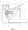
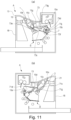
- FIG. 2 is a cross-sectional view of the main assembly of the electrophotographic image forming apparatus (the electrophotographic image forming apparatus main assembly, the image forming apparatus main assembly) An and the process cartridge (hereinafter referred to as cartridge B) of the electrophotographic image forming apparatus according to an embodiment of the present invention.
- Figure 3 is a cross-sectional view of cartridge B.
- the apparatus main assembly A is a part of the electrophotographic image forming apparatus excluding the cartridge B.
- An electrophotographic image forming apparatus (image forming apparatus) shown in Figure 2 is a laser beam printer using an electrophotographic process in which the cartridge B is dismountably mounted to the apparatus main assembly A.
- An exposure device 3 laser scanner unit
- for forming a latent image on the electrophotographic photosensitive drum 62 as the image bearing member of the cartridge B at the time when the cartridge B is mounted in the apparatus main assembly An is provided.
- a sheet tray 4 containing recording materials (hereinafter referred to as a sheet material PA) to be subjected to image formation.
- the electrophotographic photosensitive drum 62 is a photosensitive member (electrophotographic photosensitive member) used for forming an electrophotographic image.
- a pickup roller 5a, a pair of feeding rollers 5b, a pair of feeding rollers 5c, a transfer guide 6, a transfer roller 7, a feeding guide 8, a fixing device 9, a pair of discharge rollers 10, a discharge tray 11, and so on are sequentially arranged.
- the fixing device 9 comprises a heating roller 9a and a pressure roller 9b.
- the electrophotographic photosensitive drum (hereinafter referred to as photosensitive drum 62 or simply drum 62) is rotationally driven in the direction of an arrow R at a predetermined circumferential speed (process speed).
- the charging roller (charging member) 66 to which the bias voltage is applied contacts with the outer peripheral surface of the drum 62 to uniformly charge the outer peripheral surface of the drum 62.
- the exposure device 3 outputs a laser beam L in accordance with image information.
- the laser beam L passes through the laser opening 71h provided in the cleaning frame 71 of the cartridge B and scans and is incident on the outer peripheral surface of the drum 62.
- an electrostatic latent image corresponding to the image information is formed on the outer peripheral surface of the drum 62.
- the toner T in the toner chamber 29 is stirred and fed by the rotation of the feeding member (stirring member) 43 to a toner supply chamber 28.
- the toner T is carried on the surface of the developing roller 32 by the magnetic force of the magnet roller 34 (stationary magnet).
- the developing roller 32 is a developer carrying member which carries a developer (toner T) on the surface thereof in order to develop a latent image formed on the drum 62.
- the layer thickness on the peripheral surface of the developing roller 32 as the developer carrying member is regulated.
- the toner T is supplied to the drum 62 in accordance with the electrostatic latent image to develop the latent image.
- the drum 62 is an image bearing member for carrying the latent image and the image (toner image, developer image) formed with toner on the surface thereof.
- the sheet material PA stored in the lower portion of the apparatus main assembly An is fed out of the sheet tray 4 in timed relation with the output of the laser beam L, by the pickup roller 5a, the feeding roller pair 5b, and the feeding roller pair 5c. Then, the sheet material PA is fed to the transfer position between the drum 62 and the transfer roller 7 along the transfer guide 6. At this transfer position, the toner image is sequentially transferred from the drum 62 to the sheet material PA.
- the sheet material PA to which the toner image is transferred is separated from the drum 62 and fed to the fixing device 9 along a conveyance guide 8. And, the sheet material PA passes through the nip portion between a heating roller 9a and a pressure roller 9b which constitute the fixing device 9. Pressure and heat fixing process are performed in this nip portion, so that the toner image is fixed on the sheet material PA.
- the sheet material PA subjected to the fixing process of the toner image is fed to the discharge roller pair 10 and discharged to the discharge tray 11.
- the cleaning unit 60 is a unit including the photosensitive drum 62.
- the charging roller 66, the developing roller 32, the transfer roller 7, and the cleaning blade 77 act as a process means acting on the drum 62.
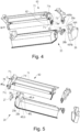
- FIG. 3 is a sectional view of the cartridge B
- Figure 4 and Figure 5 are perspective views illustrating the structure of the cartridge B.
- the screws for joining the parts are omitted.
- the cartridge B includes a cleaning unit (photosensitive member holding unit, drum holding unit, image bearing member holding unit, first unit) 60 and a developing unit (developer carrying member holding unit, second unit) 20.
- the process cartridge is a cartridge in which at least one of the electrophotographic photosensitive member and the process means acting thereon are integrally formed into a cartridge, and the process cartridge is mountable to and dismountable from the main assembly (apparatus main assembly) of the electrophotographic image forming apparatus.
- process means include charging means, developing means and cleaning means.
- the cleaning unit 60 includes the drum 62, the charging roller 66, the cleaning member 77, and a cleaning frame 71 for supporting them.
- the drive side drum flange 63 provided on the drive side is rotatably supported by the hole 73a of a drum bearing 73.
- the drum bearing 73 plus the cleaning frame 71 can be called a cleaning frame.
- the hole portion (not shown) of the non-driving side drum flange is rotatably supported by the drum shaft 78 press-fitted in the hole portion 71c provided in the cleaning frame 71 and is constituted to be supported.
- Each drum flange is a supported portion rotatably supported by the bearing portion.
- the charging roller 66 and the cleaning member 77 are disposed in contact with the outer peripheral surface of the drum 62.
- the cleaning member 77 includes a rubber blade 77a which is a bladeshaped elastic member formed of rubber as an elastic material, and a support member 77b which supports the rubber blade.
- the rubber blade 77a is counterdirectionally in contact with the drum 62 with respect to the rotational direction of the drum 62. In other words, the rubber blade 77a is in contact with the drum 62 so that the tip portion thereof faces the upstream side in the rotational direction of the drum 62.
- the waste toner removed from the surface of the drum 62 by the cleaning member 77 is stored in the waste toner chamber 71b formed by the cleaning frame 71 and the cleaning member 77.
- a scooping sheet 65 for preventing the waste toner from leaking from the cleaning frame 71 is provided at the edge of the cleaning frame 71 so as to be in contact with the drum 62.
- the charging roller 66 is rotatably mounted in the cleaning unit 60 by way of charging roller bearings (not shown) at the opposite end portions in the longitudinal direction of the cleaning frame 71.
- the longitudinal direction of the cleaning frame 71 (the longitudinal direction of the cartridge B) is substantially parallel to the direction (the axial direction) in which the rotational axis of the drum 62 extends. Therefore, in the case of simply referring to the longitudinal direction or merely the axial direction without particular notice, the axial direction of the drum 62 is intended.
- the charging roller 66 is pressed against the drum 62 by the charging roller bearing 67 being pressed toward the drum 62 by the biasing member 68.
- the charging roller 66 is rotationally driven by the drum 62.
- the developing unit 20 includes a developing roller 32, a developing container 23 which supports the developing roller 32, a developing blade 42, and the like.
- the developing roller 32 is rotatably mounted in the developing container 23 by bearing members 27 ( Figure 5 ) and 37 ( Figure 4 ) provided at the opposite ends.
- a magnet roller 34 is provided inside the developing roller 32.
- a developing blade 42 for regulating the toner layer on the developing roller 32 is provided in the developing unit 20, a developing blade 42 for regulating the toner layer on the developing roller 32 is provided.
- a gap maintaining member 38 is mounted to the developing roller 32 at the opposite end portions of the developing roller 32, and the gap maintaining member 38 and the drum 62 are in contact with each other, so that the developing roller 32 is held with a small gap from the drum 62.
- a blowing prevention sheet 33 for preventing toner from leaking from the developing unit 20 is provided at the edge of the bottom member 22 so as to be in contact with the developing roller 32.
- a feeding member 43 is provided in the toner chamber 29 formed by the developing container 23 and the bottom member 22. The feeding member 43 stirs the toner accommodated in the toner chamber 29 and conveys the toner to the toner supply chamber 28.
- the cartridge B is formed by combining the cleaning unit 60 and the developing unit 20.
- the center of the developing first support boss 26a of the developing container 23 with respect to the first hanging hole 71i on the driving side of the cleaning frame 71, and the center of the developing second supporting boss 23b with respect to the second suspending hole 71j on the non-driving side are aligned with each other. More particularly, by moving the developing unit 20 in the direction of the arrow G, the first developing supporting boss 26a and the second developing supporting boss 23b are fitted in the first hanging hole 71i and the second hanging hole 71j.
- the development unit 20 is movably connected to the cleaning unit 60. More specifically, the developing unit 20 is rotatably (rotatably) connected to the cleaning unit 60.
- the cartridge B is constructed by assembling the drum bearing 73 to the cleaning unit 60.
- the first end portion 46 La of the driving side biasing member 46 L is fixed to the surface 23c of the developing container 23, and the second end portion 46 Lb abuts against the surface 71k which is a part of the cleaning unit.
- the first end 46 Ra of the non-driving side biasing member 46 R is fixed to the surface 23k of the developing container 23 and the second end 46Rb is in contact with the surface 71l which is a part of the cleaning unit.
- the driving side urging member 46L ( Figure 5 ) and the non-driving side urging member 46R ( Figure 4 ) comprises compression springs, respectively.
- the urging force of these springs urges the developing unit 20 against the cleaning unit 60 to urge the developing roller 32 reliably toward the drum 62 by the driving side urging member 46L and the non-driving side urging member 46R.
- the developing roller 32 is held at a predetermined distance from the drum 62 by the gap maintaining members 38 mounted to opposite end portions of the developing roller 32.
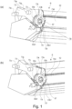
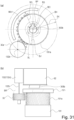
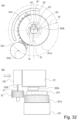
- Parts (a) and part (b) of Figure 1 are perspective views of cartridges for explaining the shape around the drive transmission part.
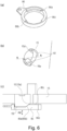
- Part (a) of Figure 6 is a perspective view of a cylindrical cam
- part (b) of Figure 6 is a perspective view of the driving side plate as viewed from the outside of the apparatus main assembly A
- part (c) of Figure 6 is a sectional view in which a cylindrical cam is mounted to the driving side plate (The direction indicated by the arrow in part (b) of Figure 6 ).
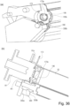
- Part (a) of Figure 7 is a cross-sectional view of the image forming apparatus link portion for explaining the link structure
- part (b) of Figure 7 is a cross-sectional view of the image forming apparatus drive unit for explaining the movement of the drive transmission member.
- Part (a) of Figure 8 is a cross-sectional view of the driving side guide portion of the image forming apparatus for explaining the mounting of the cartridge
- Part (b) of Figure 8 is a cross-sectional view of the non-driving side guide portion of the image forming apparatus for explaining the mounting of the cartridge
- Figure 9 is an illustration of the image forming apparatus driving train portion for explaining the positional relationship of the drive train before closing the opening/closing door
- Part (a) of Figure 10 is an illustration just before engagement of the image forming apparatus positioning portion for explaining the positioning of the process cartridge B in the longitudinal direction.
- Part (b) of Figure 10 is an illustration after engagement of the image forming apparatus positioning portion for explaining the positioning of the process cartridge B in the longitudinal direction.
- Part (a) of Figure 11 is a drive-side cross-sectional view of the image forming apparatus for explaining the positioning of the cartridge.
- Part (b) of Figure 11 is a non-driving side sectional view of the image forming apparatus for explaining the positioning of the cartridge.
- Part (a) of Figure 12 is a cross-sectional view of the image forming apparatus link portion for explaining the link structure
- Part (b) of Figure 12 is a cross-sectional view of the image forming apparatus drive portion for explaining the movement of the drive transmission member.
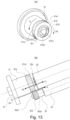
- Part (a) of Figure 13 is a perspective view of the drive transmission member for explaining the shape of the drive transmission member.
- Part (b) of Figure 13 is an illustration of the drive transmitting portion of the main assembly A for explaining the drive transmitting portion.
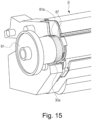
- Figure 15 is a perspective view of a drive unit of the image forming apparatus for explaining the engagement space of the drive transmitting portion.
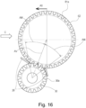
- Figure 16 is a cross-sectional view of the drive transmission member for explaining the engagement space of the drive transmission member.
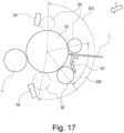
- Figure 17 is a sectional view around the drum 62 of the apparatus main assembly A for explaining the arrangement of the developing roller gear.
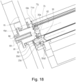
- Figure 18 is a cross-sectional view of the drive transmission member for explaining the engagement of the drive transmission member.
- the opening/closing door 13 is rotatably mounted on the driving side plate 15 and the non-driving side plate 16.
- the cylindrical cam 86 is rotatable on the drive side plate 15 and movable in the longitudinal direction AM, and it has two inclined surface portions 86a, 86b, and furthermore, it has one end portion 86c continuous with the slope on the non-driving side in the longitudinal direction.
- the driving side plate 15 has two inclined surface portions 15d and 15e opposed to the two inclined surface portions 86a and 86b and an end surface 15f opposed to the one end portion 86c of the cylindrical cam 86.
- the cylindrical cam link 85 is provided with bosses 85a, 85b at the opposite ends.
- the bosses 85a, 85b are rotatably mounted to the mounting hole 13a provided in the opening/closing door 13 and the mounting hole 86e provided in the cylindrical cam 86, respectively.
- the rotating cam link 85 moves in interrelation with the opening/closing door 13.
- the cylindrical cam 86 is rotated by the movement of the rotating cam link 85, and the inclined surfaces 86a, 86b first contact the inclined surface portions 15d, 15e provided on the driving side plate 15.
- the drive transmission member 81 is fitted to the drive transmission member bearing 83 at one end (fixed end 81c) on the drive side in the axial direction, and is supported so as to be rotatable and movable in the axial direction. Also, in the drive transmission member 81, the central portion 81d in the longitudinal direction has a clearance M relative to the drive side plate 15. Also, the drive transmission member 81 has an abutment surface 81e, and the cylindrical cam 86 has the other end portion 86d opposite to the abutment surface 81e.
- the drive transmission member spring 84 is a compression spring, wherein one end portion 84a is in contact with a spring seat 83a provided on the drive transmission member bearing 83, and the other end portion 84b is in contact with a spring seat 81f provided on the drive transmission member 81.
- the drive transmission member 81 is urged toward the non-drive side in the axial direction (left side in part (b) of Figure 7 ).
- the abutment surface 81e of the drive transmission member 81 and the other end portion 86d of the cylindrical cam 86 are in contact with each other.
- the drive transmission member 81 When the cylindrical cam 86 moves in the longitudinal direction toward the driving side (the right side in part (b) of Figure 7 ), the drive transmission member 81 is pushed by the cylindrical cam 86 and moves toward the drive side as described above. This causes the drive transmission member 81 to be in the retracted position. In other words, the drive transmission member 81 retracts from the movement path of the cartridge B, thereby securing the space for mounting the cartridge B in the image forming apparatus main assembly A.
- the driving side plate 15 has an upper guide rail 15 g and a guide rail 15h as a guide means
- the non-driving side plate 16 has a guide rail 16d and a guide rail 16e.
- the drum bearing 73 provided on the driving side of the cartridge B has a guided portion 73 g and a rotation stopped portion 73c.
- the guided portion 73 g and the rotation stopping portion 73c are disposed on the upstream side of the axis of the coupling projection 63b (see part (a) of Figure 1 , details will be described later) (Arrow AO side in Figure 16 ).
- the direction in which the cartridge B is mounted is substantially perpendicular to the axis of the drum 62.
- upstream and downstream are defined in the movement direction of the cartridge B just before the mounting to the apparatus main assembly A is completed.
- the cleaning frame 71 is provided with positioned portion (a portion to be positioned) 71d and a rotation stopped portion 71g on the non-driving side in the longitudinal direction.
- the guided portion 73g and the rotated stop portion 73c of the driven side of the cartridge B is guided by the guide rail 15g and the guide rail 15h of the main assembly A.
- the positioned portion 71d and the rotation stopped portion 71g are guided by the guide rail 16d and the guide rail 16e of the apparatus main assembly A.
- a developing roller gear (developing gear) 30 is provided at the end portion of the developing roller 32 ( Figure 9 and part (b) of Figure 13 ). That is, the developing roller gear 30 is mounted on the shaft portion (shaft) of the developing roller 32.
- the developing roller 32 and the developing roller gear 30 are coaxial with each other and rotate about the axis Ax2 shown in Figure 9 .
- the developing roller 32 is disposed such that the axis Ax2 thereof is substantially parallel to the axis Ax1 of the drum 62. Therefore, the axial direction of the developing roller 32 (developing roller gear 30) is substantially the same as the axial direction of the drum 62.
- the developing roller gear 30 is a drive input gear (a cartridge side gear, a driving input member) to which a driving force is inputted from the outside of the cartridge B (that is, the apparatus main assembly A).
- the developing roller 32 is rotated by the driving force received by the developing roller gear 30.
- an open space 87 is provided on the side of the driving side of the cartridge B on the drum 62 side of the developing roller gear 30, so that the developing roller gear 30 and the coupling projection 63b is exposed to the outside.
- the coupling projection 63b is formed on the drive side drum flange 63 mounted on the end of the drum ( Figure 9 ).
- Coupling projection 63b is a coupling portion (drum side coupling portion, cartridge side coupling portion, photosensitive member side coupling portion, input coupling portion, drive input portion) ( Figure 9 ), To which A driving force is inputted from the outside of the cartridge B (that is, the apparatus main assembly A).
- the coupling projection 63b is disposed coaxially with the drum 62. In other words, the coupling projection 63b rotates about the axis Ax1.
- the driving side drum flange 63 including the coupling projection 63b may be referred to as a coupling member (a drum side coupling member, a cartridge side coupling member, a photosensitive member side coupling member, a drive input coupling member, a input coupling member) is there.
- the side on which the coupling projection 63b is provided is the drive side, and the opposite side corresponds to the non-drive side.
- the developing roller gear 30 has a gear portion (input gear portion, cartridge side gear portion, developing side gear portion) 30a and an end surface 30a1 on the driving side of the gear portion (Parts (a), part (b) thereof, and Figure 9 in Figure 1 ).
- Teeth (gear teeth) formed on the outer periphery of the gear portion 30a are helical teeth inclined with respect to the axis of the developing roller gear 30.
- the developing roller gear 30 is a helical tooth gear (part (a) in Figure 1 ).
- helical tooth also includes a shape in which a plurality of projections 232a are arranged along a line inclined with respect to the axis of the gear to substantially form the helical tooth portion 232b ( Figure 14 ).
- the gear 232 has a large number of projections 232b on its circumferential surface.
- the set of five projections 232b can be regarded as forming a row inclined with respect to the axis of the gear.
- Each of the rows of these five projections 232b corresponds to the tooth of the aforementioned gear portion 30a.
- the drive transmission member (drive output member, main assembly side drive member) 81 has a gear portion (main assembly side gear portion, output gear portion) 81a for driving the developing roller gear 30.
- the gear portion 81a has an end surface 81a1 at the end on the non-driving side (parts (a), part (b) thereof of Figure 13 ).
- the teeth (gear teeth) formed on the gear portion 81a are also helical teeth inclined with respect to the axis of the drive transmission member 81.
- the helical gear portion is also provided on the drive transmission member 81.
- the drive transmission member 81 is provided with a coupling recess 81b.
- the coupling recess 81b is a coupling portion (main assembly side coupling portion, output coupling portion) provided on the device main assembly side.
- the coupling recess 81b is formed by forming a recess capable of coupling with a coupling projection 63b provided on the drum side, in a projection (cylindrical portion) provided at the free end portion of the drive transmission member 81.
- the space (space) 87 ( Figure 1 ) constituted so that the gear portion 30a and the coupling projection 63b are exposed allows the gear portion 81a of the drive transmission member 81 to be placed when the cartridge B is mounted in the apparatus main assembly A. Therefore, the space 87 is larger than the gear portion 81a of the drive transmission member 81 ( Figure 15 ).
- an imaginary circle having the same radius as that of the gear portion 81a is drawn about the axis of the drum 62 (the axis of the coupling projection 63b).
- the inside of the imaginary circle is a space where no constituent element of the cartridge B exists.
- the space defined by this imaginary circle is included in the space 87 mentioned above. That is, the space 87 is larger than the space defined by the imaginary circle.
- the drive transmission member 81 does not interfere with the cartridge B when the cartridge B is mounted to the apparatus main assembly A. As shown in Figure 15 , the space 87 permits the mounting of the cartridge B to the apparatus main assembly A by placing the drive transmission member 81 therein.
- the gear teeth formed in the gear portion 30a are disposed in a position close to the peripheral surface of the drum 62.
- a distance AV (the distance along the direction perpendicular to the axis) from the axis of the drum 62 to the free end portion of the gear tooth of the gear portion 30a (tooth tip) is 90 % Or more and 110 % or less of the radius of the drum 62.
- the radius of the drum 62 is 12 mm, and the distance from the axis of the drum 62 to the free end portion of the gear tooth of the gear portion 30a (tooth tip) is 11.165 mm or more and 12.74 or less. In other words, the distance from the axis of the drum 62 to the free end portion of the gear tooth of the gear portion 30a (tooth tip) is within the range of 93 % to 107 % of the radius of the drum.
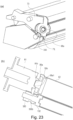
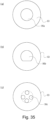
- the end surface 30a1 of the gear portion 30a of the developing roller gear 30 is disposed so as to be positioned at the position closer to the driving side (outside of the cartridge B) than the leading end portion 63b1 of the coupling projection 63b of the driving side drum flange 63 ( Figure 9 , Figure 33 ).
- the gear teeth of the gear portion 30a have exposed portions exposed from the cartridge B ( Figure 1 ).
- the range of 64 ° or more of the gear portion 30a is exposed.
- both sides of the developing roller gear 30 with respect to this reference line are exposed at least in a range of 32 degrees or more.
- the angle AW indicates the angle from the reference line to the position where the gear portion 30a starts to be covered by the driving side developing side member 26 with the center (axis) of the developing roller gear 30 as the origin, and AW ⁇ 32 ° is satisfied.
- the total exposure angle of the gear portion 30a can be expressed as 2AW, and as described above, the relationship of 2AW ⁇ 64 ° is satisfied.
- the gear portion 30a of the developing roller gear 30 is exposed from the driving side developing side member 26 so as to satisfy the above relationship, the gear portion 81a meshes with the gear portion 30a without interfering with the driving side developing side member 26, and therefore drive transmission is possible. And, at least a part of the exposed portion of this gear portion 30a is disposed on more outside (drive side) of the cartridge B than the leading end 63b1 of the coupling projection 63b and faces the axis of the drum ( Figure 1 , Figure 9 , Figure 33 ).
- Figure 33 shows a state in which the outer end portion 30a1 of the gear portion 30a is disposed on the arrow D1 side of the free end portion 63b1 of the coupling projection 63b.
- the arrow D1 extends toward the outside in the axial direction.
- the gear portion 30a of the developing roller gear 30 and the gear portion 81a of the drive transmission member 81 can be brought into meshing engagement with each other in the process of mounting the above-described cartridge B to the apparatus main assembly A.
- the center (axis) of the gear portion 30a is disposed on the upstream side (the side of the arrow AO in Figure 16 ) of the center (axis) of the drum 62.
- the line connecting between the center of the drum 62 and the center of the charging roller 66 is defined as a reference line (starting line) providing the angle reference (0 °).
- the center (axis) of the developing roller gear 30 is in the angle range of 64 ° to 190 ° from the reference line to the downstream side of the rotational direction of the drum 62 (clockwise direction in Figure 17 ).
- the half line extending from the center of the drum 62 to the center of the charging roller 66 from the center of the drum 62 is taken as the starting line, and the rotational direction of the drum is taken as a positive direction of the angle.
- the angle on the polar coordinate formed about the center of the developing roller satisfies the following relationship. 64 ° ⁇ angle on the polar coordinates having the center of developing roller ⁇ 190 ° .
- the unit (developing unit 20) provided with the developing roller gear 30 can move relative to the unit (cleaning unit 60) provided with the drum 62 and the coupling projection 63b. That is, the developing unit 20 is rotatable relative to the cleaning unit 60 about the development first support boss 26a and the second development support boss 23b ( Figures 4, 5 ) as the rotation center (rotation axis). Therefore, the distance between the centers of the developing roller gear 30 and the drum 62 (the distance between the axes) is variable, and the developing roller gear 30 can move within a certain range relative to the axis of the drum 62 (the axis of the coupling projection 63b).
- the drum bearing 73 is provided with a portion 73h to be engaged (engaged portion) as a part to be positioned (axial aligned portion) in the longitudinal direction (axial direction).
- the driving side plate 15 of the apparatus main assembly A has an engaging portion 15j which can engage with the engaged portion 73h.
- the engaged portion 73h of the cartridge B is engaged with the engaging portion 15j of the apparatus main assembly A in the above-described mounting process, whereby the position, in the longitudinal direction (axial direction) of the cartridge B is determined, (Part (b) of Figure 10 ).
- the engaged portion 73h is in the form of a slit (groove) (part (b) of Figure 1 ). This slit communicates with the space 87. That is, the slit (the fitted portion 73h) forms a space opened (open) to the space 87.
- Figure 33 is an illustration (schematic diagram) showing the arrangement of the engaged portion 73h with respect to the gear portion 30a or the coupling projection 63b.
- the slit (engaged with portion 73h) is a space formed between two portions (the outer portion 73h1 and the inner portion 73h2 of the engaged portion 73h) arranged along the axial direction the.
- the inner end portion (the inner portion 73h2) of the engaged portion 73h is disposed inside (on the arrow D2 side) the outer end portion 30a1 of the gear portion 30a.
- the outer end portion (outer portion 73h1) of the fitted portion 73h is disposed on the side (arrow D1 side) outer than the free end portion 63b of the coupling projection 63b.
- the driving side plate 15 has an upper positioning portion 15a, a lower positioning portion 15b, and a rotation stopper portion 15c.
- the non-driving side plate 16 has a positioning portion 16a and a rotation stopping portion 16c.
- the drum bearing 73 includes an upper portion to be positioned (positioned portion) (a first portion to be positioned (positioned portion), a first projection, a first projecting portion) 73d and a lower portion to be positioned (positioned portion) (a second portion to be positioned (positioned portion), a second projection, a second overhanging portion) 73f.
- the cartridge pressing members 1 and 2 are rotatably mounted to the opposite axial ends of the opening/closing door 13.
- the cartridge pressing springs 19, 21 are mounted to the opposite ends in the longitudinal direction of the front plate provided in the image forming apparatus A, respectively.
- the drum bearing 73 is provided with a portion 73e to be pressed (pressed portion) as the urging force receiving portion, and the cleaning frame 71 has a portion 71o to be pressed (pressed portion) on the non-driving side ( Figure 3 ).
- the upper positioned member 73d, the lower positioned member 73f, and the rotation stopping member 73c of the cartridge B are contacted to the upper positioning portion 15a, the lower positioning portion 15b, the rotation stopping portion 15c, respectively.
- cartridge B and drum 62 are positioned relative to each other on the driving side.
- the to-be-positioned portion 71d of the cartridge B and the rotation-stopped portion 71 g come into contact with the positioning portion 16a and the rotation stopper portion 16c of the apparatus main assembly A, respectively.
- this cartridge B and drum 62 are positioned with each other on the non-driving side.
- the upper positioned member 73d and the lower positioned member 73f are placed in the neighborhood of the drum. Also, the upper positioned member 73d and the lower positioned member 73f are aligned along the rotational direction of the drum 62.
- the drum bearing 73 it is necessary to secure a space (arcuate recess) 73l for disposing the transfer roller 7 ( Figure 11 ) between the upper positioned portion 73d and the lower positioned portion 73f. Therefore, the upper positioned portion 73d and the lower positioned portion 73f are arranged apart from each other.
- the upper positioned portion 73d and the lower positioned portion 73f are projections projecting inward in the axial direction from the drum bearing 73. As described above, it is necessary to secure a space 87 around the coupling projection 63b. Therefore, the upper positioning portion 73d and the lower positioning portion 73f do not project outward in the axial direction, but instead they project inward to secure the space 87.
- the upper positioned portion 73d and the lower positioned portion 73f are projections arranged so as to partially cover the photosensitive drum 62.
- the positioned portions 73d, 73f are overhanging portions that project inwardly in axial direction of the photosensitive drum 62.
- the upper positioned portion 73d and the photosensitive drum 62 are projected on the axis of the drum 62, at least some of the projected areas of the upper positioned portion 73d and the photosensitive drum 62 overlap each other.
- the lower positioned portion 73f is the same as the upper positioned portion 73d.
- the upper positioned portion 73d and the lower positioned portion 73f are disposed so as to partially cover the driving side drum flange 63 provided at the end of the photosensitive drum 62.
- the upper positioned portion 73d and the driving side drum flange 63 are projected on the axis of the drum 62, at least parts of the projected areas of the upper positioned 73d and the driving side drum flange 63 overlap each other.
- the lower positioned portion 73f is the same as the upper positioned portion 73d.
- the pressed portions 73e and 71o are projecting portions of the frame of the cleaning unit arranged on one end side (drive side) and the other end side (non-drive side) of the cartridge B with respect to the longitudinal direction, respectively. Especially the pressed portion 73e is provided on the drum bearing 73. The pressed portions 73e and 71o project in a direction crossing the axial direction of the drum 62 and separating from the drum 62.
- the drive side drum flange 63 has a coupling projection 63b on the drive side, and the coupling projection 63b has a free end portion 63b1 at the free end thereof.
- the drive transmission member 81 has a coupling recess 81b and a free end portion 81b1 of the coupling recess 81b on the non-driving side.
- the drive transmitting member 81 at the retracted position moves to the non-drive side (the side approaching the cartridge B) in the longitudinal direction by the drive transmission member spring 84. Since the gear teeth of the gear portion 81a and the gear portion 30a are inclined with respect to the moving direction of the drive transmission member 81, the gear teeth of the gear portion 81a abuts to the gear teeth of the gear portion 30a by the movement of the drive transmission member 81. At this point of time, the movement of the drive transmission member 81 to the non-drive side is stopped.
- the drum bearing 73 has a recess bottom surface 73i.
- the drive transmitting member 81 has a bottom portion 81b2 as a positioning portion on the bottom of the coupling recess 81b.
- the coupling recess 81b of the drive transmission member 81 is a hole having a substantially triangular cross section. As viewed from the non-driving side (the cartridge side, the opening side of the coupling recess 81b), the coupling recess 81b is twisted in the counterclockwise direction N as it goes to the driving side (the back side of the coupling recess 81b).
- the gear portion 81a of the drive transmission member 81 is a helical gear including gear teeth twisted in the counterclockwise direction N as approaching to the drive side as viewed from the non-drive side (cartridge side).
- the coupling recess 81b and the gear portion 81a are inclined toward the rear end (fixed end 81c) of the drive transmission member 81 in a direction opposite to the rotational direction CW of the drive transmission member 81 (twisting).
- the gear portion 81a and the coupling recess 81b are arranged on the axis of the drive transmission member 81 such that the axis of the gear portion 81a and the axis of the coupling recess 81b overlap each other.
- the gear portion 81a and the coupling recess 81b are arranged coaxially (concentrically).
- the coupling projection 63b of the driving side drum flange 63 has a substantially triangular cross-section and has a projection shape (protrusion, projection).
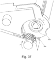
- the coupling projection 63b is twisted in the counterclockwise direction O from the drive side (the tip side of the coupling projection 63b) toward the non-drive side (the bottom side of the coupling projection 63b) ( Figure 37 ).
- the coupling projection 63b is inclined (twisted) in the counterclockwise direction (the direction of rotation of the drum) as it is distant from the outside toward the inside of the cartridge in the axial direction.
- the portion (ridge line) forming the corner (the apex of the triangle) of the triangular prism is a driving force receiving portion which actually receives the driving force from the coupling recess 81b.
- the driving force receiving portion is inclined in the rotational direction of the drum as goes inward from the outside of the cartridge in the axial direction.
- the inner surface (inner peripheral surface) of the coupling recess 81b serves as a driving force applying portion for applying the driving force to the coupling projection 63b.
- the shape of the cross-section of the coupling projection 63b and the coupling recess 81b is not a strict triangle (polygon) because of the corners being beveled or rounded, but it is called a substantial triangle (polygon).
- the coupling projection 63b has a shape of substantially twisted triangular prism (polygonal prism).
- the shape of the coupling projection 63b is not limited to such a shape.
- the shape of the coupling projection 63b may be changed if it can be coupled with the coupling recess 81b, that is, if it can be engaged therewith and driven thereby.
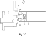
- three bosses 163a may be arranged at the apexes of the triangle shape, in which each boss 163a is twisted with respect to the axial direction of the drum 62 ( Figure 19 ).
- the gear portion 30a of the developing roller gear 30 is a helical gear and has a shape twisted (inclined) in the clockwise direction P from the drive side toward the non-drive side ( Figure 37 ).
- the gear tooth (helical tooth) of the gear portion 30a is inclined in the clockwise direction P (the direction of rotation of the developing roller or the developing roller gear) in the axial direction of the gear portion 30a from the outside toward the inside of the cartridge (twisted). That is, the gear portion 30a is inclined (twisted) in the direction opposite to the rotational direction of the drum 62 as goes from the outside toward the inside in the axial direction.
- the drive transmission member 81 is rotated by the motor (not shown) in the clockwise direction CW (reverse direction of arrow N in Figure 13 ) as viewed from the non-drive side (cartridge side). Then, thrust force (force generated in the axial direction) is generated by meshing engagement between the helical teeth of the gear portion 81a of the drive transmission member 81 and the gear portion 30a of the developing roller gear 30.
- the force FA in the axial direction (longitudinal direction) is applied to the drive transmission member 81, and the drive transmission member 81 tends to move toward the non-drive side (closer to the cartridge) in the longitudinal direction. In other words, the drive transmission member 81 approaches and contacts to the coupling projection 63b.
- the gear portion 81a of the drive transmission member 81 has a tooth helicity so as to move by 5 to 8.7 mm per tooth in the axial direction ( Figure 13 ). This corresponds to the helix angle of the gear portion 81a being 15 ° to 30 °. Further, the helix angle of the developing roller gear 30 (the gear portion 30a) is also 15 ° to 30 °. In this embodiment, 20 ° is selected as the helix angle between the gear portion 81a and the gear portion 30a.
- the drive transmission member 81 attracted by the coupling projection 63b is positioned in the longitudinal direction (axial direction) by the free end portion 81b1 of the drive transmission member 81 contacting the recess bottom surface 73i of the drum bearing 73.
- a reaction force FB of the force FC acts on the drum 62, and due to this reaction force (against force) FB, the drum 62 moves in the longitudinal direction toward the drive side (approaching the drive transmission member 81, the outside of the cartridge B).
- the drum 62 and the coupling projection 63b are attracted toward the side of the drive transmission member 81.
- the free end portion 63b1 of coupling projection 63b of the drum 62 abuts against bottom 81b2 of coupling recess 81b.
- the drum 62 is also positioned in the axial direction (longitudinal direction).
- the coupling projection 63b and the coupling recess 81b are attracted toward each other, whereby the positions of the drum 62 and the drive transmission member 81 in the axial direction are determined.
- the drive transmission member 81 is in the driving position. In other words, the drive transmission member 81 is in a position for transmitting the driving force to the coupling projection 63b and the gear portion 30b, respectively.
- the position of the center at the free end portion of the drive transmission member 81 is determined relative to the drive side drum flange 63 by the triangular alignment action of the coupling recess 81b.
- the drive transmission member 81 is aligned with the drum flange 63, and the drive transmission member 81 and the photosensitive member are coaxial. By this, the drive is transmitted from the drive transmission member 81 to the developing roller gear 30 and the driving side drum flange 63 with high accuracy.
- the coupling recess 81b and the coupling projection 63b engaging with the coupling recess 81b can also be regarded as an aligning portion. That is, the engagement between the coupling recess 81b and the coupling projection 63b causes the drive transmission member 81 and the drum to be coaxial with each other.
- the coupling recess81b is referred to as the main assembly side aligning portion (the aligning portion on the image forming apparatus side), and the coupling projecting 63b is referred to as the cartridge side aligning portion.
- the engagement of the coupling is assisted by the force FA and force FC acting on the drive transmission member 81 toward the non-drive side.
- the positional accuracy in the longitudinal direction between the gear portion 30a of the developing roller gear 30 and the gear portion 81a of the drive transmission member 81 is improved, and therefore, the width of the gear portion 30a of the developing roller gear 30 can be reduced. It is possible to downsize the cartridge B and the apparatus main assembly A for mounting the cartridge B.
- the gear portion 81a of the drive transmission member 81 and the gear portion 30a of the developing roller gear 30 have helical teeth.
- the helix teeth provide higher contact ratios of the gears than the spur teeth.
- the direction in which the helical teeth of the gear portion 30a and the gear portion 81a are inclined is selected so that the force (force FA and force FB) that the gear portion 30a and the gear portion 81a attract to each other is produced.
- the coupling recess 81b provided in the drive transmission member 81 and the coupling provided in the end portion of the photosensitive drum 62A force that brings the coupling projection 63b closer to each other is generated.
- the drive transmitting member 81 moves toward the cartridge B side, and the coupling recess 81b approaches the coupling projection 63b.
- the direction in which the coupling projection 63b (driving force receiving portion) is inclined with respect to the axis of the drum and the direction in which the helical teeth of the gear portion 30a of the developing roller gear 30 is inclined with respect to the axis of the gear portion 30a are opposite to each other ( Figure 38 ).
- the drive transmission member 81 is urged toward the coupling projection 63b by the elastic member (drive transmission member spring 84) (part (a) of Figure 7 ).
- the force of the drive transmission member spring 84 can be reduced, correspondingly to the force FA and the force FC (part (b) of Figure 13 ).
- the frictional force between the drive transmission member spring 84 and the drive transmission member 81 which is produced when the drive transmission member 81 rotates, is also reduced, and therefore, the torque required to rotate the drive transmission member 81 is reduced.
- the load applied to the motor for rotating the drive transmission member 81 can also be reduced.
- sliding noise produced between the drive transmission member 81 and the drive transmission member spring 84 can also be reduced.
- the drive transmission member 81 is biased by the elastic member (spring 84), but the elastic member is not necessarily required.
- the elastic member can be eliminated.
- the force of attracting the coupling projection 63b and the coupling recess 81b to each other is produced by the engagement between the gear portion 81a and the gear portion 30a.
- the coupling projection 63b of the drive side drum flange 63 couples with the coupling recess 81b of the drive transmission member 81 in the state that the drive transmission member 81 is rotating.
- the coupling projection 63b is inclined (twisted) in the rotational direction of the photosensitive drum toward the inside from the outside of the cartridge with respect to the axial direction of the drum 62.
- the coupling projection 63b is inclined (twisted) along the rotational direction of the drive transmission member 81, and therefore, the coupling projection 63b is easy to be coupled with the coupling recess 81b.
- the helical gear is used as the developing roller gear 30 that engages with the drive transmission member 81.
- another gear may be used as long as drive transmission is possible.
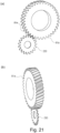
- a thin spur tooth gear 230 that can enter the tooth gap 81e of the drive transmission member 81 is usable.
- the thickness of the flat teeth is set to 1 mm or less.
- the gear portion 81a of the drive transmission member 81 has helical teeth, and therefore, the force for directing the drive transmission member 81 toward the non-driving side is produced by the meshing engagement between the gear portion 81a and the spur gear 230 ( Figure 21 ).
- the coupling projection 63b drum 62
- the developing roller gear 30 the developing roller 32
- the layout of the main assembly A and cartridge B may be modified to make the directions of rotation of the coupling projection 63b (drum 62) and the developing roller gear 30 opposite to those in this embodiment.
- the coupling projection 63b and the developing roller gear 30 rotate in opposite directions. One of them rotates clockwise and the other rotates counterclockwise.
- the direction of the rotation of the developing roller gear 30 is clockwise.
- the developing roller gear 30 is used as the driving input gear engaging with the driving transmission member 81, but another gear may be used as the driving input gear.
- Figure 22 shows the drive input gear 88 that meshes with the drive transmission member 81, the developing roller gear 80 provided on the developing roller, the idler gears 101 and 102, and the feeding gear (stirring gear, developer feeding gear) 103.
- the driving force is transmitted from the drive input gear 88 to the developing roller gear 80 by way of one idler gear 101.
- the idler gear 101 and the developing roller gear 80 are a drive transmission mechanism (a cartridge side drive transmission mechanism, a development side drive transmission mechanism) for transmitting a driving force from the drive input gear 88 to the developing roller 32.
- the idler gear 102 is a gear for transmitting the driving force from the drive input gear 88 to the stirring gear 103.
- the feeding gear 103 is mounted to the feeding member 43 ( Figure 3 ), and the feeding member 43 is rotated by the driving force received by the feeding gear 103.
- the cartridge B in order to provided the rotational direction of the developing roller 32 in the direction of the arrow P ( Figure 1 ) and to transmit the driving to the developing roller 32, the cartridge B is provided with an odd number of gears.
- the number of gears for transmitting the drive to the developing roller 32 is three, that is, the developing roller gear 80, the idler gear 101, and the driving input gear 88.
- the number of gears for transmitting the drive to the developing roller 32 is one, that is, only the developing roller gear 30.
- the cartridge B is provided with a drive transmission mechanism (a cartridge side drive transmission mechanism, a development side drive transmission mechanism) for rotating the developing roller 32 in the same rotational direction as the drive input gear 88.
- a drive transmission mechanism a cartridge side drive transmission mechanism, a development side drive transmission mechanism
- the rotational direction of the developing roller 32 also rotates clockwise.
- the rotational directions of the drive input gear 88 and the developing roller 32 are clockwise when the cartridge B is viewed from the driving side.
- the drive input gear (30, 88) is driven from the drive transmission member 81 independently from the coupling projection 63b.
- the cartridge B has two input portions (drive input portions) for receiving driving force from the outside of cartridge B (that is, apparatus main assembly A), one for the cleaning unit, and one for the developing unit.
- the stability of rotation of the photosensitive drum is enhanced. This is because there is no need to transmit the driving force (rotational force) between the photosensitive drum and another member (developing roller, for example), and therefore, when rotation unevenness occurs at this different member (developing roller, for example), its rotation unevenness is less likely to affect the rotation of the photosensitive drum.
- the force in the direction of the arrow FA (part (b) in Figure 13 ) is applied to the drive transmission member 81 to assist the coupling of the coupling recess 81b and the coupling projection 63b.
- a load (torque) needs to be generated when the drive input gear 88 rotates.
- the drive input gear 88 may not be constituted so as to receive the driving force for rotating the developing roller 32.
- the driving force received by the drive input gear 88 may be transmitted only to the feeding member 43 ( Figure 3 ) without being transmitted to the developing roller 32.
- a gear or the like for transmitting the driving force from the drum 62 to the developing roller 32 is required for the cartridge B.
- part (a) of Figure 18 is a cross-sectional view of the image forming apparatus drive portion as viewed from the direction opposite to the mounting direction of the cartridge B in order to explain the distance of the drive transmitting portion.
- Part (b) of Figure 24 is a cross-sectional view of the image forming apparatus drive portion as viewed from the drive side for explaining a distance of the drive transmitting portion.
- Part (a) of Figure 25 is a cross-sectional view of the image forming apparatus drive portion as viewed from the drive side for explaining a gap of the coupling portion.
- Part (b) of Figure 25 is a cross-sectional view of the image forming apparatus drive portion as viewed from the drive side for explaining the gap of the coupling portion.
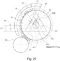
- Figure 27 is a sectional view of the image forming apparatus for explaining the range of a regulating portion (stopper) as viewed from the drive side.
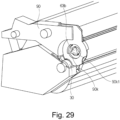
- the drum bearing 73 is provided with an inclination regulating portion (movement regulating portion, position regulating portion, stopper) 73j for regulating the movement of the drive transmission member 81 to restrict (suppress) the inclination of the drive transmission member 81
- the drive transmission member 81 has a cylindrical portion 81i (part (a) of Figure 24 ) on the non-driving side (the side close to the cartridge B).
- the cylindrical portion 81i is a cylindrical portion (projection) in which the coupling recess 81b is formed.
- the drive transmission member 81 is inclined. That is, as described above, only the fixed end 81c (see the part (a) of Figure 24 : the end far from the cartridge B) of the drive transmission member 81 which is the end portion on the drive side is supported, and therefore, the drive transmission member 81 is inclined with the drive side end portion 81c (fixed end) as a fulcrum. Then, the end (free end, tip) of the drive transmission member 81 on the side where the coupling recess 81b is provided moves.
- the restricting portion 73j is provided in the cartridge B, so that the inclination of the drive transmitting member 81 is restricted (regulated) within a certain range. That is, when the drive transmission member 81 is inclined, the restriction portion 73j supports the drive transmission member 81, thereby suppressing the inclination thereof from increasing.
- the regulating portion 73j of the drum bearing 73 has an arcuate curved surface portion provided so as to face the axis of the drum 62 (the axis of the coupling projection 63b).
- the restricting portion 73j can also be regarded as a projecting portion projecting so as to cover the drum axis.
- the structure is such that between the regulating portion 73i and the drum axis, there is provided a space in which the constituent elements of the process cartridge B are not disposed, and the drive transmission member 81 is disposed in this space.
- the regulating portion 73i faces the space 87 shown in Figure 1 , and the regulating portion 73i forms an edge (outer edge) of the space 87.
- the restricting portion 73j is disposed at a position where to suppress the movement (inclination) of the drive transmission member 81 by the meshing force FD can be suppressed.
- the direction in which the meshing force FD is produced is determined by a transverse pressure angle ⁇ of the gear portion 81a (that is, the transverse pressure angle ⁇ of the developing roller gear 30).
- the direction in which the meshing force FD is generated is inclined relative to the direction (half line) LN extending from the center 62a of the photosensitive drum (that is, the center of the drive transmission member 81) toward the center 30b of the developing roller gear 30 by (90 + ⁇ ) degrees toward the upstream AK in the rotational direction of the photosensitive drum 62.
- the standard angle ⁇ is 21.2 °.
- the transverse pressure angles ⁇ of the gear portion 81a and the gear portion 30a of this embodiment are also 21.2 °. In this case, the inclination of the meshing force FD relative to the arrow LN is 111.2 °.
- another value can be used as the transverse pressure angles of the gear portion 81a and the gear portion 30a can be employed, and the direction of the meshing force FD is also different in that case.
- the transverse pressure angle ⁇ also varies depending on the twist angle of the helical gear, and the transverse pressure angle ⁇ is preferably 20.6 degrees or more and 22.8 degrees or less.
- the restricting portion 73j is disposed so as to cross the half line FDa.
- the half line FDa is a line provided by inclining (rotating) the half line LN by 90 + ⁇ degree toward the upstream side with respect to the rotational direction of the drum 62 with the center of the drum 62 as the origin (axis, fulcrum).
- the half line FDa is inclined by 111.2 degrees relative to the half straight line LN.
- the regulating portion 73j is disposed on this line FDa, and the regulating portion 73j is preferably disposed adjacent to the half line FDa. More specifically, it is desirable that at least a part of the regulating portion 73j is disposed somewhere in the range of plus or minus 15 ° with respect to the half line FDa.
- the half line FDa is a line obtained by rotating the half straight line LN toward the upstream side in the rotational direction of the drum 62 by (90 + ⁇ ) degrees.
- the regulating portion 73j is preferably in the range of (75 + ⁇ ) degrees to (105 + ⁇ ) degrees on the upstream side in the drum rotational direction with respect to the half straight line LN with the center of the drum 62 as the origin.
- the preferable value of the transverse pressure angle ⁇ is 20.6 degrees or more and 22.8 degrees or less
- the preferable range in which the restricting portion 73j is disposed is 95.6 degrees or more and 127.8 degrees or less with respect to the half line LN.
- the transverse pressure angle ⁇ is 21.2 degrees
- the preferable range of the regulating portion 73j is 96.2 degrees or more and 126.2 degrees or less.
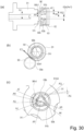
- a plurality of regulating portions 73j may be provided so that they are disposed separately on respective sides of the half line FDa with half line FDa interposed therebetween ( Figure 26 ).
- the restricting portion 73j can be regarded as being disposed across the line FDa.
- the regulating portion 73j is disposed on the upstream side AO ( Figure 16 ) of the center (axis) of the coupling projection 63b in the cartridge mounting direction C (part (a) of Figure 11 ). This is to prevent the restriction portion 73j from hindering the mounting of the cartridge B.
- a range (region) in which the regulating portion 73j is disposed in the drum bearing 73 can also be described as follows.
- the restricting portion 73j is disposed in a region AL opposite to the side where the drum 62 is exposed (the side where the drum 62 faces the transfer roller 7) with respect to the line LA passing through the drum center 62a and the gear center 30b.
- a cover or a shutter for covering the drum 62 may be provided in the cartridge B, and the drum 62 may not be exposed.
- the side where the drum 62 is exposed means the side where the drum 62 is exposed when the cover, the shutter, and so on are removed.
- the range (region AL) in which the regulating portion 73j is arranged can also be described as follows, using the circumferential direction (rotational direction) of the photosensitive drum 62.
- a half line (original line) LN extending from the center 62a of the drum 62 toward the center 30b of the gear portion 30a of the developing roller gear 30 is drawn.
- the region AL is a range (region) that is larger than 0 ° and does not exceed 180 ° toward the upstream side (arrow AK side) in the drum rotation direction with respect to the half line LN.
- the range AL is in the upstream side (arrow AK side), with respect to the drum rotation direction O, of the center point MA between the drum center 62a and the developing roller gear center 3 b and is does not exceed a straight line (extension line) LA passing through the center 6 a of the drum 62 and the center 30b of the gear portion 30a of the developing roller gear 30
- the regulating portion 73j is in a position overlapping the gear portion 81a of the drive transmission member 81 in the longitudinal direction. That is, the regulating portion 73j also overlaps the developing roller gear 30 in the longitudinal direction.
- the developing roller gear 30 and the regulating portion 73j are projected on the axis line Ax2 of the developing roller gear 30, at least parts of their projected regions overlap each other. That is, the regulating portion 73j is close to the gear portion 81a (the gear portion 30a) where the meshing force is produced. Therefore, when the meshing force received by the drive transmission member 81 is supported by the restricting portion 73j, bending of the drive transmission member 81 is suppressed.
- At least a part of the restricting portion 73j is on the outer side (arrow D1 side in Figure 34 ) of the coupling projection 63b.
- the distances shown below are those (distances in the radial direction of the drum 62) measured along a direction perpendicular to the axial direction of the drum 62.
- S be the distance from the axis (center 62a) of the drum 62 to the regulating portion 73j.
- U be the radius of the tooth tip of the gear portion 81a of the drive transmission member 81.
- AC be the distance from the center 81j of the drive transmission member 81 to the radially outermost portion of the coupling recess.
- AD be the distance from the center 63d of the driving side drum flange 63 to the radially outermost portion of the coupling projection 63b.
- AA be the distance between the regulating portion 73j and the tooth tip of the gear portion 81a of the drive transmission member 81.
- AB be an amount of deviation between the center of the coupling projection 63b and the center of the coupling recess 81b when the drive transmission member 81 is inclined by the amount of the gap relative to the regulating portion 73j (when the drive transmission member 81 is inclined and the gear portion 81a is in contact with the regulating portion 73j) (part (b) of Figure 25 ).
- the distance is measured along the axial direction of the drive transmission member 81 from the fixed end 81c which is the fulcrum of the inclination of the drive transmission member 81.
- X be the distance in the axial direction from one end portion 81c of the drive transmission member 81 to the gear portion 81a.
- W be the distance in the axial direction from one end portion 81c of the drive transmission member 81 to the coupling recess 81b.
- V be the gap between the coupling projection 63b of the drive side drum flange 63 and the coupling recess 81a of the drive transmission member 81 in a state that there is no misalignment.
- the gap V is the smallest value among the inter-surface distances of the two coupling portions (the distance measured along the direction perpendicular to the axis of the drum 62 and the radial distance).
- the clearance V between the couplings may satisfy the following.
- V AC ⁇ AD > AB
- the coupling projection 63b and the coupling recess portion 81b can tolerate the misalignment amount AB and are engaged.
- the shortest gap V between the coupling portions also is different. That is, if the phases of the coupling portions are not aligned, the shortest clearance V between the coupling projection 63b and the coupling recess portion 81b is smaller than (AC - AD).
- the gap V may be smaller than the misalignment amount AB, depending on the cases.
- the coupling projection 63b and the coupling recess portion 81b are engaged. This is because the coupling recess 81b contacts the coupling projection 63b while rotating. It can be engaged (coupled) with the coupling projection 63b at the timing when the coupling recess 81b is rotated to such an angle as to satisfy "V > AB".
- the clearance V is maximized when the phases of the coupling portions are aligned.
- the operation when the coupling engages will be described. Before the coupling recess 81b of the drive transmission member 81 and the coupling projection 63b of the drive side drum flange 63 are engaged with each other, the meshing force FD is applied to the drive transmission member 81.
- the meshing force FD is the force produced by the engagement between the gear portion 81a of the drive transmission member 81 and the gear portion 30a of the developing roller gear 30 as described above.
- the drive transmission member 81 is inclined with the drive transmission member bearing 83 as a fulcrum, in the direction FD in which the meshing force is applied, by the amount of the gap AA between the regulating portion 73j of the drum bearing 73 and the gear portion 81a.
- the misalignment AB of the coupling recess 81b and the coupling projection 63b provided by this inclination is smaller than the gap V between the coupling recess 81b and the coupling projection 63b in a predetermined phase.
- each part of the drive transmission member 81 applicable to the drum 62 having a radius of 12 mm are as follows.
- the distance AC from the center of the coupling recess 81b to the apex of the substantially equilateral triangular shape of the coupling recess 81b is 6.5 mm and the radius AE of the inscribed circle of substantially equilateral triangle shape of the coupling recess 81b is 4.65 mm.
- the substantially equilateral triangle shape of the coupling recess 81b is not a strictly equilateral triangle but its apex (corner) is beveled into an arc shape.
- the radius AF of the lightening portion 81b3 of the coupling recess portion is 4.8 mm
- the radius U of the tip circle of the gear portion 81a of the coupling recess portion is 12.715 mm
- the distance X from the one end portion 81c to the non-driving side end surface 81a1 is 30.25 mm
- the distance W from the one end portion 81c to the free end portion 81b 1 of the coupling recess is 33.25 mm.
- the shortest distance V between the coupling recess 81b and the coupling projection 63b satisfies the following relationship. 0 ⁇ V ⁇ 1.7
- the lower limit of V occurs when the size of the triangular shape of the coupling recess 81b is equal to the size of the triangular shape of the coupling projection 63b, and the lower limit value of V is "0".
- the dimensions are shown when the coupling projection 63b is made as large as possible within a range capable of engaging with the coupling recess 81b.
- the clearance V between the coupling projection 63b and the coupling recess 81b is minimum, and therefore, the allowable inclination of the drive transmission member 81 is small. Therefore, in order to reduce the inclination of the drive transmission member 81, it is necessary to make the regulating portion 73j closer to the regular position of the gear portion 81a.
- the dimensions are shown when the coupling projection 63b is made as small as possible within the range capable of engaging with the coupling recess 81b.
- the gap V between the coupling projection 63b and the coupling recess portion 81b is maximized, and therefore, even if the drive transmission member 81 is relatively greatly inclined, the coupling projection 63b and the coupling recess 81b can engage with each other. That is, the regulating portion 73j can relatively tolerate the inclination of the drive transmission member 81, and therefore, the regulating portion 73j can be relatively greatly spaced apart from the regular position of the gear portion 81a.
- the size of the coupling projection 63b is closest to the maximum and the radial direction amount of engagement between the coupling projection 63b and the coupling recess 81b (the region where both are engaged) is maximized.
- V gap between couplings
- S the distance from the center of the drum 62 to the regulating portion 73j
- the distance AD from the center of the coupling projection 63b of the driving side drum flange 63 to the apex thereof is 6.498 mm.
- the coupling projection 63b has a dimension slightly smaller than the distance 6.5 mm from the center of the coupling recess 81b to the apex of the triangle, the amount of radial direction amount of engagement between the coupling portions is substantially maximum.
- the radius AG of the inscribed circle inscribed in a triangle constituting the coupling projection 63b of the driving side drum flange 63 is 4.648 mm.
- the substantially triangular shape possessed by the coupling projection 63b is not a strictly equilateral triangle but an apex (corner) is beveled into an arc shape.
- the distance S from the center 62a of the drum 62 to the regulating portion 73j of the drum bearing is 12.716 mm which is slightly larger than the radius U of the addendum circle of the gear portion 81a.
- the misalignment amount AB between the coupling portions when the drive transmission member 81 is inclined by the gap AA relatively to the regulating portion 73j is amplified by the difference between the positions of the regulating portion 73j and the coupling portion in the longitudinal direction.
- the shortest gap V between the coupling projection 63b and the coupling recess 81b when the phases of the coupling portions are aligned is 0.002 mm ("6.5 - 6.498" or "4.65 - 4.648", whichever is smaller).
- the gap V between the couplings is larger than the misalignment AB between the coupling portions, so that the engagement is possible.
- the radial distance from the center of the drum 62 to the outermost portion of the coupling portion is preferably larger than 4.8 mm, and the radial distance from the center of the drum 62 to the regulating portion 73j is preferably larger than 12.715 mm.
- the size of the coupling projection 63b is made as small as possible and the radial amount of engagement between the coupling projection 61b and the coupling recess 81b (the region where both are engaged) is made as small as possible.
- V gap between couplings
- S distance from the center of the drum 62 to the regulating portion 73j
- the distance AD between the center of the coupling projection 63b of the drive side drum flange 63 and the apex is 4.801 mm. This is a value slightly larger than the radius of 4.8 mm of the lightening 81b3 of the coupling recess 81b and is a diameter at which the amount of radial direction engagement between the couplings is almost minimum. If the distance AD of the coupling projection 63b is shorter than the radius of the lightening portion 81b3, the tip of the projection 63b does not engage with the coupling recess 81b with the result that the drive transmission is disabled.
- the radius AG of the triangle inscribed circle of the coupling projection 63b is 2.951 mm.
- the distance S between the center 62a of the drum 62 and the regulating portion 73j of the drum bearing is 14.259 mm.
- the gap V between the coupling projection 63b and the coupling recess 81b when the phases of the coupling portions is in alignment with each other is 1.699 mm ("6.5 - 4.801" or "4.65 - 2.951, whichever is the smaller). Therefore, even if the drive transmission member 81 is inclined by the engagement force FD, the gap V between the couplings is larger than the misalignment AB between the coupling portions, so that the coupling projection 63b and the coupling recess 81b can be engaged.
- the radial distance from the center of the drum 62 to the outermost portion of the coupling projection 63b is larger than 4.8 mm, and the radial distance from the center of the drum 62 to the restricting portion 73j is smaller than 14.262 mm.
- the radial distance S from the center 62a of the drum 62 to the regulating portion 73j of the drum bearing is preferably larger than 12.715 mm and smaller than 14.262 mm.
- the coupling projection 363b having a more general shape is used without limiting the shape of the coupling projection to a substantially regular triangle is taken as an example, and a preferable arrangement regarding the restricting portion 73j will be described as general.
- the shape of the coupling recess is assumed to be a virtually strict equilateral triangle for the sake of convenience of explanation.
- FIG. 28 an example of a coupling projection including a general shape is shown in parts (a) and part (b) of Figure 28 .
- the coupling projection 363b shown in parts (a) and part (b) of Figure 28 has a substantially cylindrical shape and further has a projection 363b1 provided on the outer periphery of the column.
- the coupling projection 363b receives the driving force by the projection 363b1.
- the minimum equilateral triangle BD circumscribing the coupling projection 363b is considered, and this regular triangle BD as a virtual coupling projection.
- the center of gravity of the equilateral triangle BD is made to coincide with the center of the coupling projection 363b (the center of the drum 62), and the size of the equilateral triangle BD is minimized.
- the arrangement of the restricting portion 73j corresponding to this virtual coupling projection (equilateral triangle DB) will be considered.
- a circle inscribed in the imaginary coupling projection is a circle BE, and the radius thereof is BA.
- the coupling recess When the coupling recess has an equilateral triangular shape, the coupling recess needs to be larger than the equilateral triangle BD in order for the coupling recess to engage the imaginary coupling projection (equilateral triangle BD). That is, the size of the equilateral triangle BD can also be deemed as being the lower limit of the size that the coupling recess can have.
- the maximum shape that the coupling recess can have will be considered.
- the circle BU circumscribing the imaginary coupling projection (equilateral triangle BD) is considered, and the radius thereof is AZ.
- an equilateral triangle BQ having this circle BU as the inscribed circle is drawn.
- the equilateral triangle BQ is the maximum (upper limit) of the equilateral triangle shape that can be selected as the coupling recess. If the coupling recess becomes larger than the equilateral triangle BQ, the coupling recess cannot contact with the imaginary coupling projection BD, and therefore, the drive transmission is impossible.
- This equilateral triangle BQ is taken as the maximum coupling recess.
- AY be the shortest distance between the equilateral triangles when these two equilateral triangles BD and BQ are in the same phase.
- Distance AY corresponds to the difference between the radius (AZ) of the inscribed circle BU inscribed in the equilateral triangle BQ and the radius (BA) of the inscribed circle BE inscribed in the equilateral triangle BD.
- the distance between the imaginary coupling projection and the coupling recess is the above-mentioned distance AY as the upper limit. If the misalignment distance of the coupling recess with respect to the virtual coupling projection is smaller than AY, the coupling recess can be engaged with the imaginary coupling projection.
- the misalignment distance between the couplings is equal to or larger than the gap BC between the tooth tip of the gear portion 81a of the drive transmission member and the regulating portion 73j. Therefore, in order for the coupling recess to engage with the imaginary coupling projection BD, the gap BC between the gear portion 81a of the drive transmission member and the restricting portion 73j needs to be at least smaller than the distance AY. This is shown in the formula, BC ⁇ AY
- the gap BC is the difference between the distance BB from the drum center to the regulating portion 73j and the radius of the addendum circle of the gear portion 81a.
- the tooth tip of the gear portion 81a of the drive transmission member can extend to the tooth bottom of the gear portion 30a of the developing roller gear 30. That is, the tooth tip of the gear portion 81a can be extended to such an extent that it does not reach the tooth bottom. If the shortest distance from the drum center to the bottom of the developing roller gear 30 is AX, the upper limit of the radius of the addendum circle 81a of the gear portion 81a is also AX.
- the gap BC between the tooth tip of the gear portion 81a and the regulating portion 73j is always larger than "BB-AX", that is,
- BC > BB-AX The distance BB from the center of the drum to the restricting portion 73j using the relational expression of "BC > BB-AX" and the aforementioned "BC ⁇ AY" satisfies the following conditions: BB ⁇ AX ⁇ AY BB ⁇ AY + AX
- the regulating portion is positioned closest to the center of the drum.
- the radius of the addendum circle of the gear portion 81a is required to be larger than the distance BF (the distance measured in the direction perpendicular to the axis of the drum) from the center of the drum 62 to the tooth tip of the gear portion 30a of the developing roller.
- the regulating portion 73j and the tooth tips of the drive transmission member 81a do not contact with each other during image formation.
- the distance BB (the distance measured in the direction perpendicular to the axis of the drum) from the center of the drum 62 to the regulating portion 73j is required to be larger than the distance BF (the distance measured in a direction perpendicular to the axis of the second axis) from the center of the drum 62 to the tooth tip of the gear portion 30a of the developing roller. It is necessary to satisfy the following from the above two conditions. BB > BF
- the regulating portion 73j is disposed in a range that satisfies the following relation with respect to the center of the drum (the axis of the drum, the axis of the input coupling). BF ⁇ BB ⁇ AX + BA
- BB the distance measured from the center of the photosensitive member (the axis of the photosensitive member, the axis of the coupling projection) to the regulating portion 73j measured along the direction perpendicular to the axis of the photosensitive member:
- BA the radius of the inscribed circle inscribed in the equilateral triangle at the time when drawing the minimum equilateral triangle circumscribing the coupling projection while aligning the center of gravity of the equilateral triangle with the axial line of the drum (axial line of the coupling projection):
- the regulating portion 73j is formed by a continuous surface. More specifically, the regulating portion 73j is a curved surface (circular arc surface) which is opened toward the axis line of the drum 62 and is curved in an arc shape. In other words, it is a bay shape (bay portion) opened toward the axis of the drum 62.
- the regulating portion 89j may be formed by a plurality of portions (plural surfaces 89j) intermittent in the rotational direction of the drum 62.
- the regulating portion can be regarded as forming a bay shape (bay portion) which opens to the axis of the drum 62.
- the regulating portion is one continuous portion or a plurality of intermittent portions, but, the restricting portion shown in Figure 1 and the restricting portion shown in Figure 26 are both deemed as having an arc shape (a bay shape, a curved surface portion, a curved portion) that opens to the axis of the drum 62.
- the restricting portion shown in Figure 1 and the restricting portion shown in Figure 26 are both deemed as having an arc shape (a bay shape, a curved surface portion, a curved portion) that opens to the axis of the drum 62.
- the triangle-shaped alignment action of the coupling projection 63b and the coupling recess portion 81b is utilized as a means for aligning the center of the drive transmission member 81 with the center of the drum 62. That is, the coupling projection 63b and the coupling recess 81b are in contact at three points, so that the axis of the coupling projection 63b and the axis of the coupling recess 81b are aligned with each other.
- the drive transmission member 81 and the photosensitive drum coaxial, the accuracy of the center-to-center distance (distance between the axes) between the gear portion 81a and the gear portion 30a can be easily maintained, and the drive is stably transmitted to the developing roller gear 30.
- one of the drive transmission member 81 and the drive side drum flange 63 may be provided with a cylindrical boss (projection), and the other may be provided with a hole to be fitted with the boss. Even with such a structure, the axis of the drive transmission member 81 and the axis of the drum 62 can be overlapped.
- Figure 38 shows such a modified example.
- the drive transmission member 181 shown in Figure 38 has a projection (boss) 181c at the center of the coupling recess 181b.
- the projection 181c is provided so as to overlap with the axis of the drive transmission member 181 and is a projection projecting along its axis.
- the coupling projection shown in Figure 38 has a recess (recess) for engaging with the projection 181c at the center thereof.
- the recess is provided so as to overlap with the rotation axis of the drum 62 and is a recess recessed along this axis.
- the driving side drum flange 63 has a flange portion 63c.
- the cleaning frame 71 is provided with a drum regulating rib 71m (a drum regulating portion, a drum longitudinal position regulating portion, a drum axial direction position regulating portion).
- the drum regulating rib 71m is provided on the non-driving side of the flange portion 63c of the driving side drum flange 63 with respect to the longitudinal direction, and faces the flange portion 63c with a gap therebetween.
- the developing roller gear 30 has an end surface 30a2 on the non-driving side of the gear portion 30a.
- the developing container 23 is provided with a developing roller gear restricting rib 23d (a gear regulating portion, a gear longitudinal position regulating portion, a gear axial line position regulating portion).
- the developing roller gear restricting rib 23d is disposed on the non-driving side in the axial direction with respect to the non-driving side end surface 30a2 of the gear portion 30a, and faces the non-driving side end surface 30a2 a gap therebetween.
- the developing roller gear restricting rib 23d disposed on the driving side of the cartridge B restricts the developing roller gear 30 from moving toward the non-driving side in the longitudinal direction.
- the positional accuracy in the axial direction of the gear portion 30a of the developing roller gear 30 before the gear portion 30a of the developing roller gear 30 meshes with the gear portion 81a of the drive transmission member 81 is improved. Therefore, the gear width of the gear portion 30a of the developing roller gear 30 can be reduced.
- the cartridge B and the apparatus main assembly An in which the cartridge B is mounted can be downsized.
- the gear portion 81a In order to break the engagement between the gear portion 81a and the gear portion 30a, the gear portion 81a must move in a direction away from the gear portion 30a by the amount equal to or more than the engagement amount AH between the gear portions. Therefore, the regulating portion 73j of the drum bearing 73 is provided so as not to hinder the movement of the drive transmission member 81 when the gear portion 81a separates from the gear portion 30a.
- the direction in which the gear portion 81a of the drive transmission member 81 moves away from the gear portion 30a of the developing roller gear 30 is indicated by the arrow AI along the direction in which the line connecting the center 81j of the drive transmission member 81 and the center 30b of the developing roller gear 30 extends.
- the restricting portion 73j is not provided in the arrow AI direction. That is, it is preferable that the regulating portion 73j is not disposed so as to crosses the straight line LA, and the drive transmission member 81 does not contact the restricting portion 73j when the gear portion 81a disengages from the gear portion 30a.
- the drive transmission member 81 does not contact the recess peripheral surface 73k of the drum bearing 73.
- the drive transmission member 81 is retracted to such a position that it does not contact the recess circumferential surface 73k of the drum bearing 73.
- the drive transmission member 81 is in the position retracted to such an extent that the coupling with the coupling projection 63b is broken. Therefore, in the longitudinal direction of the drive transmission member 81, the free end of the drive transmission member 81 is at substantially the same position as the free end of the recessed circumferential surface 73k or on the left side of the free end of the recessed circumferential surface 73k.
- the amount of movement of the drive transmission member 81 when retracting is short and the free end of the drive transmission member 81 at the retracted position is provided on the right side of the free end of the recessed circumferential surface 73k.
- the contact between the drive transmission member 81 and the recess circumferential surface 73k can be avoided if the following conditions are satisfied.
- Z be the distance in the radial direction from the center 62a of the drum 62 to the recess peripheral surface 73k of the drum bearing 73.
- Y be the radial distance from the center 81j of the drive transmission member 81 to the outer peripheral surface of the cylindrical portion 81i of the drive transmission member 81.
- AJ be the radial distance at the gap between the recess peripheral surface 73k and the cylindrical portion 81i.
- a recess portion is provided around the drum 62.
- the drive transmission member 81 can move within the range in which the inner peripheral surface (recess peripheral surface 73k) of the recess portion does not contact the gear portion 81a.
- the radial position of the recess peripheral surface 73k of the drum bearing 73 may be such that the distance Z from the center 62a of the drum 62 is satisfies the following: Z > AH + Y
- the drive transmission member 81 can incline in the away direction AD by an amount beyond the engagement amount AH between the gear portion 81a of the drive transmission member 81 and the gear portion 30a of the developing roller gear 30. And, disengagement between the gear portion 81a of the drive transmission member 81 and the gear portion 30a of the developing roller gear 30 is effected, so that the cartridge B can be taken out smoothly from the main assembly An of the apparatus.
- the drive transmission member 81 moves toward the coupling portion on the cartridge side due to the thrust force caused by the engagement of the helical gears with each other.
- the drive transmission member 81 is moved (inclined) by the force produced by the meshing of the gears, but the movement amount (amount of inclination) is regulated by the restricting portion provided on the cartridge side.
- the engagement (coupling) between the drive transmission member 81 and the coupling portion on the cartridge side is secured to assure reliable drive transmission.
- the drive transmission member 81 is provided with a gap that allows the drive transmission member 81 to move in the radial direction beyond the engagement height of the gear, the disengagement between the gears when removing the cartridge B from the main assembly of the apparatus is smoothly carried out. That is, the cartridge can be easily taken out.
- the coupling projection 63b is fixed to the drum 62, but a movable coupling projection may be provided.
- the coupling 263b shown in Figure 20 is movable in the axial direction with respect to the drum 62, and is urged by a spring 94 toward the driving side in a state that it receives no external force.
- the end 263a of the coupling 263b comes into contact with the drive transmission member 81.
- the coupling projection 263b can retract to the non-drive side (the side away from the drive transmission member 81) while contracting the spring 94 by the force received from the drive transmission member 81.
- the end portion 263a of the coupling projection 263b is an inclined portion (inclined surface, chamfered surface). With such a structure, when the end portion 263a contacts to the drive transmission member 81 at the time of mounting and dismounting the cartridge, the end portion 263a is tends to receive a force in the direction of retracting the coupling projection portion 263b.
- the present invention is not limited to such a structure.
- the contact portion on the drive transmission member 81 side contacting the coupling projection 263b may be an inclined portion.
- FIG. 23 A not-claimed comparative example is shown in Figure 23 .
- the drum 62 is driven by the engagement between the drive transmission member 81 and the coupling projection 63b.
- the driving of the drum 62 may be performed by the gears 330b, 95b according to the comparative example.
- the developing roller gear 330 includes not only a gear portion (input gear portion) 330a for receiving drive from the gear portion 81a of the drive transmission member 81 but also a gear portion (output gear portion) 330b for outputting a driving force toward the drum 62.
- the drum flange 95 fixed to the end portion of the drum 62 has a gear portion 95b (input gear portion) for receiving the driving force from the gear portion 330b instead of including the coupling projection.
- the drum flange 95 has a cylindrical portion 95a.
- the cylindrical portion 95a provided at the end portion of the drum 62 functions as a positioning portion for positioning the drive transmission member 81 by engaging with the coupling recess portion 81b provided at the tip of the drive transmission member 81.
- Both the coupling recess 81b and the cylindrical portion 95a act as an aligning portion for aligning the axes of the drive transmission member recess 81 and the drum 62 with each other.
- the coupling recess 81b and the cylindrical portion 95a are engaged with each other, the axes of the drum 62 and the drive transmission member 81 are substantially overlapped, and the both are coaxially arranged.
- the coupling recess 81b may be referred to as a main assembly side aligning portion (aligning recessed portion)
- the cylindrical portion 95a may be referred to as a cartridge side aligning portion (aligning projection).
- the outer peripheral surface of the cylindrical portion 95a corresponds to the aligning portion on the cartridge side.
- the lightening portion 81b3 of the coupling projection 81b corresponds to the main assembly side alignment portion.
- the circular lightening portion 81b3 engages with the outer peripheral surface of the cylindrical portion 95a, thereby aligning the drum 62 and the drive transmission member 81 with each other.
- the coupling recess portion 81b functions as a output coupling for transmitting the driving force to the coupling projection 63b.
- the coupling projection 63b is substantially triangular, by the coupling recess 81b being coupled to the coupling projection 63b, the drive transmission member 81 is centered. Therefore, the coupling recess 81b functions also as a centering(aligning) portion.
- the coupling recess 81b does not serve as a coupling portion (output coupling), but serves only as a centering recess (main assembly side alignment portion).
- the coupling recess portion 81b serves as both the output coupling and the main assembly aligning portion (the aligning recess portion), and the function of the coupling recess portion 81b provided by the structure of the drum 62 is both or either one of the function of the coupling recess portion and the centering portion.
- the outer periphery of the aligning portion on the cartridge side shown in Figure 23 is the cylindrical portion 95a forming a complete circle.
- Figure 35 show examples of the shape of the aligning portion as a schematic view.
- Part (a) of Figure 35 shows a state in which the cylindrical portion 95a shown in Figure 23 is provided on the drum flange 63.
- the shape of the aligning portion 95b constitutes only a part of a circle. If the circular arc portion of the aligning portion 95b is sufficiently larger than the circular arc shape of the lightening portion 81b3, the aligning portion 95b has a centering action.
- the distance (radius) from the center of the drum to the outermost portions of the aligning portions 95a, 95b corresponds to the radius of the lightening portion 81b3.
- the radius of the lightening portion 81b3 is 4.8 mm, and therefore, the distance (radius) from the center of the drum to the outermost portions of the aligning portions 95a, 95b, 95c is 4.8 mm or less, and the closer to 4.8 mm, the better the alignment effect is.
- the coupling recess 81b which is the main assembly side aligning portion has a substantial triangular shape in order to transmit the drive when engaged with the coupling projection 63b, and an arcuate lightening portion 81b3 is provided on a part of a side of a triangular shape.
- the main assembly side alignment portion can take another shape.
- the main assembly side aligning portion may be a substantially circular recess portion. In the case of such a main assembly side alignment section, the alignment portion 95c as shown in part (c) of Figure 35 can be used as the alignment portion on the cartridge side.
- the centering portion shown in part (c) of Figure 35 has a structure in which a plurality of projections 95c are arranged in a circular shape. That is, the circumscribed circle (circle shown by a dotted line) of the projection 95c is a circle coaxial with the drum. In addition, this circumscribed circle has a size corresponding to the recess portion of the main assembly side aligning portion. That is, the radius of the circumcircle is not more than 4.8 mm.
- any of the structures shown in part (a), part (b), and part (c) of Figure 35 can be regarded as an aligning portion that is substantially coaxial with the drum. That is, each of the aligning portions 95a, 95b, 95c is disposed so as to be centered on the axis line of the drum.
- the outer peripheral surfaces of the aligning portions 95a, 95b, 95c that is, the portions facing the opposite side of the drum axis line (in other words, the portions facing the outside in the radial direction of the drum) functions as alignment portions.
- the outer circumferential surface functioning as the aligning portion is extended so as to surround the axis of the drum.
- Each of the aligning portions 95a, 95b, 95c is exposed toward the outside of the cartridge in the axial direction.
- the structure of the cartridge as shown in Figure 23 also has the regulating portion 73j as described above.
- the positional relationship (dimensional relationship) between the developing roller gear 30 and the regulating portion 73j relative to the aligning portion may be considered similarly to the relationship (dimensional relationship) between the developing roller gear 30 and the regulating portion 73j relative to the cartridge projection 63b.
- BB the distance measured from the center of the photosensitive member (the axis of the photosensitive member, the axis of the coupling projection) to the regulating portion 73j along the direction perpendicular to the axis of the photosensitive member.
- BF the minimum distance measured from the rotation center (axis) of the photosensitive member to the tooth tip of the input gear portion (gear portion 30a) along the direction perpendicular to the axis of the photosensitive member.
- the upper limit of distance BB will be considered. It is preferable that the misalignment amount generated between the coupling recess 81b and the aligning portion 95a when the movement transmitting member 81 is inclined until the gear portion 81a comes into contact with the restricting portion 73j satisfies the following relationship. That is, it is preferable that an inclined portion 95a1 (part (a) of Figure 23 ) is provided at the tip of the aligning portion 95a, but as the width of the inclined portion 95a is measured along the radial direction of the drum, the width of the inclined portion 95a is larger than the misalignment amount.
- the inclined portion 95a1 of the aligning portion 95a comes into contact with the edge of the coupling recess 81b to assist the engagement between the coupling recess 81b and the aligning portion 95a.
- the difference between the distance BB and the radius U of the tip circle of the gear portion 81a is "BB-U", and the misalignment amount becomes larger than "BB-U".
- the width BX of the inclined portion 95a needs to be larger than "BB-U".
- the radius U of the addendum circle of the gear portion 81a is shorter than the distance AX from the center of the drum to the root of the developing roller gear. Therefore, the width BX of the inclined portion 95a is larger than "BB-AX”. BX > BB ⁇ AX
- BB the distance measured from the center of the photosensitive member (the axis of the photosensitive member, the axis of the coupling projection) to the regulating portion 73j along the direction perpendicular to the axis of the photosensitive member.
- AX the distance measured from the axis of the photosensitive member to the root of the developing roller gear along the direction perpendicular to the axis of the photosensitive member.
- the cylindrical portion 95a is provided on the drum 62.
- the alignment portion such as the cylindrical portion 95a may be provided on the frame of the cleaning unit 60 (that is, the drum bearing 73). That is, it is also conceivable that the drum bearing 73 covers the end portion of the drum 62, and the drum bearing 73 is provided with the aligning portion.
- a circular arc projection 173a for contacting the periphery of the cylindrical portion 81i is provided on the drum bearing 173.
- Part (a) of Figure 36 is a perspective view of the cartridge
- part (b) of Figure 36 is a sectional view illustrating a state in which the aligning portions of the cartridge and the main assembly driving member are engaged with each other.
- the projection 173a is engaged with the cylindrical portion 81i to provide an aligning portion for aligning the drive transmission member 81. More particularly, the inner circumferential surface of the projection 173a facing the axis side of the drum (in other words facing the radially inner side of the drum) is the aligning portion.
- This aligning portion is provided in the drum bearing 173, not in the drum flange 195. Therefore, the drum flange 195 has a gear portion 195a for receiving the driving force from the developing roller gear, but does not have the aligning portion.
- the center of the aligning portion is disposed so as to overlap the axis line of the drum. That is, the projection 173a is disposed so as to be substantially coaxial with the drum. In other words, the inner circumferential surface of the projection 173a facing the axis line side of the drum is disposed so as to surround the axis of the drum.
- a taper (inclined portion) is provided on the edge of the tip of the projection 173a, so that the cylindrical portion 81i can be easily introduced into the internal space of the projection 173a when the tip of the projection 173a hits the cylindrical portion 81i.
- the distance (radius) from the axis of the drum to the aligning portion (projection 173a) corresponds to the radius of the cylindrical portion 81i. If the radius of the cylindrical portion 81i is 7.05 mm, the radius of the projection 173a is preferably 7.05 mm or more.
- the projection 173a also functions as a restricting portion (stopper) for suppressing inclination and movement of the drive transmission member 81 by contacting the cylindrical portion 81i. That is, the projection 173a can also serve as the restricting portion 73j ( Figure 24 ).
- the structure in which the regulating portion is constituted to contact the cylindrical portion 81i will be described later in Embodiment 2.
- an inclined portion (taper, chamfer) is provided at the tip of the projection 173a, and when the drive transmission member 81 is inclined, the tip of the cylindrical portion 81i comes into contact with the inclined portion, so that the engagement between the cylindrical portion 81i and the projection 173a is assisted. That is, the inner circumferential surface of the projection 173a has a diameter increasing toward the tip of the projection 173 a.
- Figure 29 is a perspective view of a cartridge for explaining the regulating portion of the drive transmission member.
- Part (a) of Figure 30 is a cross-sectional view of the driving portion of the image forming apparatus as viewed from the opposite direction of the cartridge mounting direction to explain the regulation of the drive transmitting portion.
- Part (b) of Figure 30 is a cross-sectional view of the drive portion of the image forming apparatus as viewed from the drive side to explain the regulation of the drive transmitting portion.
- Part (c) of Figure 30 is a cross-sectional view of the driving portion of the image forming apparatus as viewed from the drive side for explaining the regulation of the drive transmitting portion.
- Part (a) of Figure 31 is a cross-sectional view of the driving portion of the image forming apparatus as viewed from the drive side to explain the regulation of the drive transmitting portion.
- Part (b) of Figure 31 is a cross-sectional view of the driving portion of the image forming apparatus as viewed from the upstream side of the process cartridge mounting direction to explain the drive transmitting portion.
- the drum bearing 90 is provided with a recess portion around the projection portion of the coupling portion.
- a restricting portion 90k1 for restricting the movement of the drive transmission member 91 is provided as a small diameter portion (a portion where the inner diameter of the recess portion is made smaller than the other portions) within the recess peripheral surface 90k (the inner peripheral surface of the recess portion).
- the regulating portion 90k1 is an arcuate curved surface portion facing the axial line side of the drum.
- the regulating portion 90k1 is a regulating portion (stopper) for suppressing the movement and inclination of the drive transmission member 91, and is a portion corresponding to the regulating portion 73j ( Figure 1 , Figure 24 , and so on) in Embodiment 1.
- the regulating portion 90k1 in this embodiment particularly the portions different from the restricting portion 73j in Embodiment 1 will be described in detail.
- the portion which regulates the inclination of the drive transmission member 91 by the restricting portion 90k1 is a cylindrical portion (cylindrical portion) 91i provided at a free end portion of the non-drive side in the axial direction of the drive transmission member 91.
- the cylindrical portion 91i corresponds to a cylindrical projection in which a coupling recess is formed.
- the regulating portion 90k1 overlaps the cylindrical portion 91i of the drive transmission member 91 in the axial direction.
- the regulating portion 90k1 in the axial direction is located outside (on the arrow D1 side) the outer circumferential surface 63b2 of the input coupling portion (the coupling projection 63b).
- the outer circumferential surface 63b2 is a portion (driving receiving portion) which receives the driving force from the coupling recess.
- at least a part of the restricting portion 90k1 is disposed outside of the leading end 63b1 of the coupling projection 63b.
- At least a part of the regulating portion 90k1 is disposed so as to overlap with the input coupling portion (the coupling projection 63b) in the axial direction. That is, when the coupling projection 63b and the regulating portion 90k1 are projected on the axis Ax 1 of the drum, at least a part of the projected regions thereof mutually overlap each other. In other words, at least a part of the regulating portion 90k1 is disposed so as to face the input coupling portion (the coupling projection 63b) provided at the end portion of the drum.
- the regulating portion 90k1 can also be regarded as a projecting portion that projects so as to cover the axis of the drum.
- AU corresponds to V and AS corresponds to S.
- AT corresponds to AA
- AP corresponds to U.
- the gear portion 81a of the drive transmission member 81 is regulated by the restricting portion 73j.
- the cylindrical portion 91i forming the outer peripheral surface of the coupling recess 91b is regulated by the regulating portion 90k1.
- the inclination of the drive transmission member 91 can be accurately regulated, in this embodiment.
- the gap between the coupling recess 91 and the coupling projection 63b is small, they can be engaged with each other. Because the dimensions (sizes) of the coupling recess 91 and coupling projection 63b are close to each other, the accuracy of drive transmission is enhanced.
- the dimensions of the respective parts of the drive transmission member 91 applicable to the drum 62 having a radius of 12 mm in this embodiment are the same as those of the drive transmission member 81 in Embodiment 1, and are as follows:
- the distance AJ from the center of the coupling recess 91b to the apex of the substantially equilateral triangle of the recess 91b is 6.5 mm
- the radius AK of the inscribed circle of the approximately triangular shape of the coupling recess 91b is 4.65 mm.
- the substantially equilateral triangle shape of the coupling recess 91b is not a pure equilateral triangle but the apex corner is beveled into an arc shape.
- the radius AN of the lightening portion 91b3 of the coupling recess 91b is 4.8 mm
- the radius AP of the cylindrical portion 91i of the drive transmission member 91 is 7.05 mm.
- the shortest distance AU between the coupling recess 91b and the coupling projection 63b satisfies the following relationship. 0 ⁇ AU ⁇ 1.7
- AU is the lower limit when the size of the triangular shape of the coupling recess 91b is equal to the size of the triangular shape of the coupling projection 63b.
- AU is the upper limit when the distance from the center of the coupling projection 63b to the apex is 4.8 mm which is the radius AC of the lightening portion of the coupling recess 91b.
- the dimensions are shown when the coupling projection 63b is enlarged to the maximum within a range that can be engaged with the coupling recess 91b. n this case, the clearance AU between the coupling projection 63b and the coupling recess 91b approaches to the lower limit, and therefore, the allowable inclination of the drive transmission member 81 becomes small. herefore, in order to reduce the inclination of the drive transmitting member 91, it is necessary to make the regulating portion 90k1 closest to the regular position of the cylindrical portion 91i.
- the dimensions are shown when the coupling projection 63b is made smallest in the range that can be engaged with the coupling recess 91b.
- the gap AU between the coupling projection 63b and the coupling recess 91b approaches to the upper limit, and therefore, the coupling projection 63b and the coupling recess 91b can engage with each other even if the drive transmission member 81 is relatively largely inclined. That is, the regulating portion 73j can relatively significantly tolerate the inclination of the drive transmission member 91, and therefore, the restricting portion 93j can be relatively largely separated from the regular position of the cylindrical portion 91i.
- the coupling projection 63b is maximized to maximize the radial amount of coupling between the coupling portions.
- the distance AQ from the center of the coupling projection 63b of the drive side drum flange 63 to the apex is slightly smaller than the distance AJ (6.5 mm) from the center of the coupling recess to the apex of the triangle, which is 6.498 mm.
- the radius AR of the triangle inscribed circle of the coupling convexity 63b of the drive side drum flange 63 is 4.648 mm.
- the radius AP of the cylindrical portion 91i of the drive transmission member 91 is 7.05 mm, and therefore, the distance AS from the center of the drum 62 to the regulating portion 90k1 of the drum bearing is 7.051 mm which is slightly larger than the radius AP.
- the gap AU between the coupling projection 63b and the coupling recess 91b when the phase of the coupling portion is in alignment is 0.002 mm ("6.5 - 6.498" or "4.65 - 4.648", whichever is smaller). Therefore, even if the drive transmission member 91 is inclined due to the meshing force, the gap AU between the couplings is larger than the misalignment AT between the coupling portions, and therefore, the coupling projection 63b and the coupling recess 91b can be coupled with each other.
- the distance in the radial direction from the center of the drum 62 to the regulating portion 90k1 is made larger than 7.05 mm.
- the coupling projection 63b is minimized so that the amount of engagement between the coupling portions is minimum.
- the distance AQ from the center to the apex of the coupling projection 63b provided on the drive side drum flange 63 is made 4.801 mm slightly larger than the radius AN of the lightening portion 91b3 of the coupling recess larger than 4.8 mm.
- the radius AR of the inscribed circle inscribed in the triangle shape of the coupling projection is 2.951 mm.
- the distance AS of the regulating portion 90k1 of the drum bearing from the center of the drum 62 is 8.749 mm.
- the gap AU between the coupling projection 63b and the coupling recess 91b when the phase of the coupling portion is in alignment is 1.699 mm ("6.5 - 4.801" and "4.65 - 2.951 ", whichever is smaller). Accordingly, even if the drive transmitting member 91 is inclined due to the meshing force, the gap AU between the couplings is larger than the misalignment AT between the coupling portions, and therefore, the coupling portions can engage with each other.
- the radial distance from the center of the drum 62 to the regulating portion 90k1 of the drum bearing is preferably less than 8.75 mm.
- the distance in the radial direction from the center of the drum 62 to the regulating portion 90k1 of the drum bearing is larger than 7.05 mm and smaller than 8.75 mm.
- the shape of the coupling projection provided on the drum 62 is not limited to a substantially equilateral triangle, and a preferable arrangement of the regulating portion in a case of a more general shape will be considered.
- the shape of the coupling recess is assumed to the equilateral triangle for convenience.
- the coupling projection 363b ( Figures 27 and 28 ) described above is used as a coupling projection having a general shape.
- the upper limit of the distance from the drum axis to the regulating portion 90k1 is considered using the regulating portion 90k1 and the drive transmission member 191 shown in Figure 31 .
- the position of the restricting portion 90k1 depends on the radius of the cylindrical portion 191i of the drive transmission member 191. That is, as the radius of the cylindrical portion 191i increases, it is necessary to move the regulating portion 90k1 away from the axis of the drum.
- the diameter of the cylindrical portion 191i of the drive transmission member 191 is larger than the diameter of the gear portion (output gear portion) 191a of the drive transmission member 191.
- the cylindrical portion 191i is disposed so as to be sandwiched between the roller portion 132a of the developing roller 132 and the developing roller gear 30, and the cylindrical portion 191i faces the shaft portion 132b of the developing roller 132.
- the distance from the center (axis) of the drum 62 to the regulating portion 90k1 is a distance BG (distance measured in the direction perpendicular to the axis of the drum).
- the distance from the center of the drum 62 to the axis of the developing roller is taken as the distance BK (the distance taken in the direction perpendicular to the axis of the drum).
- the cylindrical portion 191i does not interfere with the shaft portion 32b of the developing roller when the drive transmitting member 191 is inclined such that the cylindrical portion 191i comes into contact with the regulating portion 90k1. That is, it is desired to restrict the movement of the cylindrical portion 191i by the restricting portion 90k1 so that at least the cylindrical portion 191i does not incline beyond the axis of the developing roller. Therefore, it is preferable that the distance BG from the drum center to the regulating portion 90k1 is shorter than the distance BK from the drum center to the axis of the developing roller 132. BG ⁇ BK
- the smallest equilateral triangle BO circumscribing the coupling projection 363b ( Figure 28 ) is taken as a hypothetical coupling projection.
- the center of gravity of the equilateral triangle BO is set to be on the center of the coupling projection 363b.
- a circle inscribed in the imaginary coupling projection is a circle BP, and radius thereof is the radius BH.
- the cylindrical portion 191i of the drive transmission member needs to be larger than this inscribed circle BP. This is because if the cylindrical portion 191i is smaller than the inscribed circle BP of the hypothetical coupling projection BO, a output coupling portion for transmitting the drive to the hypothetical coupling projection BO cannot be formed in the cylindrical portion 191i.
- the distance BG from the drum center to the regulating portion 90k1 is larger than the radius of the cylindrical portion 191i, and therefore, the distance BG is larger than the radius BH of the inscribed surface BP.
- the preferable range of the regulating portion 90k1 is as follows. BH ⁇ BG ⁇ BK
- the cylindrical portion 291i of the drive transmission member 291 is smaller in diameter than the gear portion 291a and disposed so as to face the developing roller gear 30. If the diameter of the cylindrical portion 191i is enlarged as shown in Figure 31 , the cylindrical portion 191i cannot be disposed in the front of the developing roller gear 30, and the cylindrical portion 191i needs to be disposed to face the shaft portion of the developing roller. In such a case, it is necessary to increase the length of the shaft portion of the developing roller, or to increase the length of the drive transmission member.
- the distance from the center of the drum 162 to the regulating portion 90k1 is a distance BG (the distance as measured in a direction perpendicular to the axis of the drum).
- the shortest distance from the center of the drum 162 to the tooth tip of the gear portion of the developing roller gear 30 is a distance BJ (the distance as measured in a direction perpendicular to the axis of the drum).
- the distance BG from the drum center to the regulating portion 90k1 is made shorter than the distance BJ from the drum center to the tooth tip of the developing roller gear.
- the minimum circle circumscribing the coupling projection 163a is BS, and its radius is the radius BL.
- the circle BS is provided concentrically (coaxially) with the drum 162.
- a coupling recess that surrounds the entire circumference of the coupling projection 163a can be formed in the cylindrical portion 291i.
- the strength of the output coupling portion (coupling recess) can be enhanced, and the engagement between the couplings can be stabilized.
- the range of the regulating portion 90j is as follows. BJ ⁇ BG ⁇ BL
- the preferable range regarding the regulating portion can be defined as follows: BH ⁇ BJ ⁇ BG ⁇ BL ⁇ BK
- An image forming process cartridge including a structure for receiving input of a driving force from the outside is provided.
Claims (27)
- Prozesskartusche (B), die abnehmbar an einer Hauptbaugruppe (A) eines elektrophotografischen Bilderzeugungsgeräts anbringbar ist, wobei die Hauptbaugruppe (A) ein Antriebsabgabeelement (81, 91, 191, 291, 181) mit einem Abtriebszahnradabschnitt (81a, 191a, 291a) und einem Abtriebskupplungsabschnitt (81b, 181b), die koaxial zueinander liegen, hat, wobei die Prozesskartusche (B) umfasst:ein photosensitives Element (62);ein Entwicklertrageelement (32, 132, 232), das so konfiguriert ist, dass es einen Entwickler trägt, um ein latentes Bild zu entwickeln, das auf dem photosensitiven Element (62) ausgebildet ist;einen Eingangskupplungsabschnitt (63b, 163a, 263a, 363b, 463b), der an einem Endabschnitt des photosensitiven Elements (62) vorgesehen ist und in der Lage ist, mit dem Abtriebskupplungsabschnitt (81b, 181b) zu koppeln; undeinen Eingangszahnradabschnitt (30a, 88), der zu einem Kämmeingriff mit dem Abtriebszahnradabschnitt (81a, 191a, 291a) in der Lage ist;wobei der Eingangszahnradabschnitt (30a, 88) eine Schrägverzahnung zum Eingriff mit dem Abtriebszahnradabschnitt (81a, 191a, 291a) hat,wobei der Eingangszahnradabschnitt (30a, 88) so konfiguriert ist, dass sich der Eingangszahnradabschnitt (30a, 88) und der Abtriebszahnradabschnitt (81a, 191a, 291a) durch ihre Drehungen in dem Zustand zueinander hin anziehen, in dem sich der Eingangszahnradabschnitt (30a, 88) und der Abtriebszahnradabschnitt (81a, 191a, 291a) miteinander in Kämmeingriff befinden, undwobei die Prozesskartusche (B) so konfiguriert ist, dass sie an der Hauptbaugruppe (A) in einer im Wesentlichen senkrecht zu einer Achse (Ax1) des photosensitiven Elements (62) liegenden Montage- oder Demontagerichtung zu montieren und zu demontieren ist.
- Prozesskartusche (B) nach Anspruch 1, wobei der Eingangszahnradabschnitt (30a, 88) so konfiguriert ist, dass der Abtriebskupplungsabschnitt (81b, 181b) und der Eingangskupplungsabschnitt (63b, 163a, 263a, 363b, (63b, 163a, 263a, 363b, 463b) sich durch Drehungen des Eingangszahnradabschnitts (30a, 88) und des Abtriebszahnradabschnitts (81a, 191a, 291a) in dem Zustand zueinander hin anziehen, in dem der Eingangszahnradabschnitt (30a, 88) und der Abtriebszahnradabschnitt (81a, 191a, 291a) miteinander in Kämmeingriff sind.
- Prozesskartusche (B) nach Anspruch 1 oder 2, wobei der Eingangszahnradabschnitt (30a, 88) so konfiguriert ist, dass er das Antriebsabgabeelement (81, 91, 191, 291, 181) durch Drehungen des Eingangszahnradabschnitts (30a, 88) und des Abtriebszahnradabschnitts (81a, 191a, 291a) in dem Zustand zu der Kartusche hin anzieht, in dem der Eingangszahnradabschnitt (30a, 88) und der Abtriebszahnradabschnitt (81a, 191a, 291a) miteinander in Kämmeingriff sind.
- Prozesskartusche (B) nach einem der Ansprüche 1 bis 3, wobei mindestens ein Teil der schrägverzahnten Zähne des Eingangszahnradabschnitts (30a, 88) zur Außenseite der Prozesskartusche (B) hin freiliegt und der Eingangskupplungsabschnitt (63b, 163a, 263a, 363b, 463b) einen Antriebskraftaufnahmeabschnitt zur Aufnahme einer Kraft von dem Abtriebskupplungsabschnitt (81b, 181b) hat, und wobei zumindest ein Teil eines freiliegenden Abschnitts der schrägverzahnten Zähne in einer axialen Richtung des photosensitiven Elements (62) an einer Position weiter außerhalb des Eingangskupplungsabschnitts angeordnet ist und zu der Achse (Ax1) des photosensitiven Elements (62) gerichtet ist.
- Prozesskartusche (B) nach einem der Ansprüche 1 bis 4, wobei die schrägverzahnten Zähne des Eingangszahnradabschnitts (30a, 88) in der axialen Richtung des photosensitiven Elements (62) von außen nach innen zu einer Drehbewegungsrichtung des Eingangszahnradabschnitts (30a, 88) geneigt sind.
- Prozesskartusche (B) nach einem der Ansprüche 1 bis 5, wobei der Eingangskupplungsabschnitt (63b, 163a, 263a, 363b, 463b) so konfiguriert ist, dass der Abtriebskupplungsabschnitt (81b, 181b) und der Eingangskupplungsabschnitt (63b, 163a, 263a, 363b, 463b) durch Drehungen des Eingangskupplungsabschnitts (63b, 163a, 263a, 363b, 463b) und des Abtriebskupplungsabschnitts (81b, 181b) in einem Zustand zueinander hingezogen werden, in dem der Abtriebskupplungsabschnitt (81b, 181b) und der Eingangskupplungsabschnitt (63b, 163a, 263a, 363b, 463b) miteinander in Kämmeingriff sind.
- Prozesskartusche (B) nach einem der Ansprüche 1 bis 6, wobei der Eingangskupplungsabschnitt (63b, 163a, 263a, 363b, 463b) einen Antriebskraftaufnahmeabschnitt hat, der konfiguriert ist, eine Antriebskraft von dem Abtriebskupplungsabschnitt (81b, 181b) aufzunehmen, wobei der Antriebskraftaufnahmeabschnitt in der axialen Richtung des photosensitiven Elements (62) von außen nach innen zu einer Drehbewegungsrichtung des Eingangskupplungsabschnitts (63b, 163a, 263a, 363b, 463b) geneigt ist.
- Prozesskartusche (B) nach einem der Ansprüche 1 bis 7, wobei eines aus dem Eingangskupplungsabschnitt (63b, 163a, 263a, 363b, 463b) oder dem Eingangszahnradabschnitt (30a, 88) konfiguriert ist, sich im Uhrzeigersinn zu drehen, und das andere konfiguriert ist, sich gegen den Uhrzeigersinn zu drehen.
- Prozesskartusche (B) nach einem der Ansprüche 1 bis 8, wobei das Entwicklertrageelement (32) so konfiguriert ist, dass es durch eine durch den Eingangszahnradabschnitt (30a, 88) von dem Abtriebszahnradabschnitt (81a, 191a, 291a) empfangene Antriebskraft gedreht wird.
- Prozesskartusche (B) nach einem der Ansprüche 1 bis 9, wobei in einer solchen Richtung gesehen, dass der Eingangszahnradabschnitt (30a, 88) im Uhrzeigersinn dreht, das Entwicklertrageelement (32) so konfiguriert ist, dass es im Uhrzeigersinn dreht.
- Prozesskartusche (B) nach einem der Ansprüche 1 bis 10, wobei der Eingangszahnradabschnitt (30a) und das Entwicklertrageelement (32) koaxial miteinander angeordnet sind.
- Prozesskartusche (B) nach einem der Ansprüche 1 bis 11, außerdem mit einem Entwicklungszahnrad (30), das an dem Entwicklertrageelement (33) vorgesehen ist, wobei das Entwicklungszahnrad (30) den Eingangszahnradabschnitt (30a) hat.
- Prozesskartusche (B) nach einem der Ansprüche 1 bis 12, außerdem mit einem Antriebseingangszahnrad (88), das den Eingangszahnradabschnitt (30a) hat, einem Entwicklungszahnrad (30), das an dem Entwicklertrageelement (33) vorgesehen ist, und mindestens einem Zwischenrad zum Übertragen der Antriebskraft von dem Antriebseingangszahnrad (88) zu dem Entwicklungszahnrad (30).
- Prozesskartusche (B) nach einem der Ansprüche 1 bis 13, wobei ein Abstand zwischen dem Antriebszahnradabschnitt (30a, 88) und dem Antriebskupplungsabschnitt (63b, 163a, 263a, 363b, 463b) variabel ist.
- Prozesskartusche (B) nach Anspruch 14, außerdem mit einer ersten Einheit (60) mit dem Eingangskupplungsabschnitt (63b, 163a, 263a, 363b, 463b), und einer zweiten Einheit (20) mit dem Eingangszahnradabschnitt (30a, 88), wobei sich ein Abstand zwischen den Achsen des Eingangszahnradabschnitts (30a, 88) und des Eingangskupplungsabschnitts (63b, 163a, 263a, 363b, 463b) durch eine Bewegung der zweiten Einheit (20) relativ zu der ersten Einheit (60) ändert.
- Prozesskartusche (B) nach einem der Ansprüche 1 bis 15, außerdem mit einem Einstellungsabschnitt (73j, 90k1, 173a) zum Einstellen der Neigung des Antriebsabgabeelements (81, 91, 191, 291, 181).
- Prozesskartusche (B) nach Anspruch 16, wobei der Einstellungsabschnitt (73j, 90k1, 173a) die Neigung des Antriebsabgabeelements (81, 91, 191, 291, 181) einstellt, um eine Kupplung zwischen dem Eingangskupplungsabschnitt (63b, 163a, 263a, 363b, 463b) und dem Abtriebskupplungsabschnitt (81b, 181b) zu ermöglichen.
- Prozesskartusche (B) nach Anspruch 16 oder 17, wobei der Einstellungsabschnitt (73j, 90k1, 173a) so angeordnet ist, dass ein entlang einer Richtung senkrecht zur Achse (Ax1) des photosensitiven Elements (62) gemessener Abstand von der Achse (Ax1) des photosensitiven Elements (62) zu dem Einstellungsabschnitt (73j, 90k1, 173a) größer als der kürzeste, entlang der Richtung senkrecht zur Achse (Ax1) des photosensitiven Elements (62) von der Achse (Ax1) des photosensitiven Elements (62) zu einem Zahnkopf des Eingangszahnradabschnitts (30a) gemessene Abstand ist.
- Prozesskartusche (B) nach einem der Ansprüche 16 bis 18, wobei der Einstellungsabschnitt (73j, 90k1, 173a) so angeordnet ist, dass ein entlang einer Richtung senkrecht zur Achse (Ax1) des photosensitiven Elements (62) gemessener Abstand von der Achse (Ax1) des photosensitiven Elements (62) zu dem Einstellungsabschnitt (73j, 90k1, 173a) kleiner als ein entlang einer Richtung senkrecht zur Achse (Ax1) des photosensitiven Elements (62) gemessener Abstand von der Achse (Ax1) des photosensitiven Elements (62) zur Achse (Ax1) des Eingangszahnradabschnitts (30a) ist.
- Prozesskartusche (B) nach einem der Ansprüche 16 bis 19, wobei der Einstellungsabschnitt (73j, 90k1, 173a) an der gleichen Seite wie der Eingangskupplungsabschnitt in Bezug auf eine axiale Richtung des photosensitiven Elements (62) vorgesehen ist, und der Einstellungsabschnitt (73j, 90k1, 173a) der Achse (Ax1) des photosensitiven Elements zugewandt ist und in der axialen Richtung nach außen vorsteht.
- Prozesskartusche (B) nach einem der Ansprüche 1 bis 20, wobei eine Achse des Eingangszahnradabschnitts (30a, 88) in Bezug auf eine Montagerichtung der Prozesskartusche (B) an der Hauptbaugruppe (A) stromaufwärts von einer Achse des Eingangskupplungsabschnitts (63b, 163a, 263a, 363b, 463b) liegend angeordnet ist.
- Prozesskartusche (B) nach einem der Ansprüche 1 bis 21, die ferner einen geführten Abschnitt umfasst, der konfiguriert ist, geführt zu werden, wenn die Prozesskartusche (B) an der Hauptbaugruppe (A) des elektrophotografischen Bilderzeugungsgeräts angebracht wird, und der in Bezug auf die axiale Richtung des photosensitiven Elements (62)an einer Seite der Prozesskartusche (B) vorgesehen ist, an der der Eingangskupplungsabschnitt (63b, 163a, 263a, 363b, 463b) vorgesehen ist, wobei der geführte Abschnitt in Bezug auf die Montagerichtung der Prozesskartusche (B) stromaufwärts des Eingangskupplungsabschnitts (63b, 163a, 263a, 363b, 463b) liegend angeordnet ist.
- Prozesskartusche (B) nach einem der Ansprüche 1 bis 22, wobei der Eingangskupplungsabschnitt (63b, 163a, 263a, 363b, 463b) in der Lage ist, mit dem Abtriebskupplungsabschnitt (81b, 181b) zu kuppeln, der an einer Spitze des Antriebsabgabeelements (81, 91, 191, 291, 181) angeordnet ist, und
wobei der Eingangszahnradabschnitt (30a, 88) in der Lage ist, mit dem an einer äußeren Umfangsfläche des Antriebsabgabeelements (81, 91, 191, 291, 181) angeordneten Abtriebszahnradabschnitt (81a, 191a, 291a) in Kämmeingriff zu geraten. - Prozesskartusche (B) nach einem der Ansprüche 1 bis 23, außerdem mit einem Schlitz (73h), der konfiguriert ist, die Prozesskartusche (B) in der axialen Richtung des photosensitiven Elements (62) durch in Eingriff geraten mit der Hauptbaugruppe (A) zu positionieren.
- Prozesskartusche (B) nach Anspruch 24, wobei der Schlitz (73h) mit Bezug auf die axiale Richtung des photosensitiven Elements (62) auf derselben Seite der Prozesskartusche (B) wie der Eingangskupplungsabschnitt (63b, 163a, 263a, 363b, 463b) und der Eingangszahnradabschnitt (30a, 88) vorgesehen ist, und
wobei sich der Schlitz (73h) in einer Richtung senkrecht zu der axialen Richtung des photosensitiven Elements (62) erstreckt. - Prozesskartusche (B) nach einem der Ansprüche 1 bis 25, wobei ein kürzester, entlang einer Richtung senkrecht zur Achse (Ax1) des photosensitiven Elements (62) gemessener Abstand von der Achse (Ax1) des photosensitiven Elements (62) zu einem Zahnkopf des Eingangszahnradabschnitts (30a, 88) nicht weniger als 90 % und nicht mehr als 110 % des Radius des photosensitiven Elements (62) beträgt.
- Elektrophotographisches Bilderzeugungsgerät mit: einer Hauptbaugruppe (A); und einer Prozesskartusche (B) nach einem der Ansprüche 1 bis 26.
Priority Applications (2)
| Application Number | Priority Date | Filing Date | Title |
|---|---|---|---|
| EP23165417.9A EP4220307B1 (de) | 2016-06-14 | 2017-06-14 | Prozesskartusche und vorrichtung zur formung elektrofotografischer bilder |
| EP23219129.6A EP4332683A3 (de) | 2016-06-14 | 2017-06-14 | Prozesskartusche und elektrofotografische bilderzeugungsvorrichtung |
Applications Claiming Priority (3)
| Application Number | Priority Date | Filing Date | Title |
|---|---|---|---|
| JP2016118181 | 2016-06-14 | ||
| PCT/JP2017/022763 WO2017217557A1 (ja) | 2016-06-14 | 2017-06-14 | プロセスカートリッジ及び電子写真画像形成装置 |
| EP17813450.8A EP3470931B1 (de) | 2016-06-14 | 2017-06-14 | Prozesskartusche und elektrofotografische bilderzeugungsvorrichtung |
Related Parent Applications (2)
| Application Number | Title | Priority Date | Filing Date |
|---|---|---|---|
| EP17813450.8A Division EP3470931B1 (de) | 2016-06-14 | 2017-06-14 | Prozesskartusche und elektrofotografische bilderzeugungsvorrichtung |
| EP17813450.8A Division-Into EP3470931B1 (de) | 2016-06-14 | 2017-06-14 | Prozesskartusche und elektrofotografische bilderzeugungsvorrichtung |
Related Child Applications (3)
| Application Number | Title | Priority Date | Filing Date |
|---|---|---|---|
| EP23165417.9A Division-Into EP4220307B1 (de) | 2016-06-14 | 2017-06-14 | Prozesskartusche und vorrichtung zur formung elektrofotografischer bilder |
| EP23165417.9A Division EP4220307B1 (de) | 2016-06-14 | 2017-06-14 | Prozesskartusche und vorrichtung zur formung elektrofotografischer bilder |
| EP23219129.6A Division EP4332683A3 (de) | 2016-06-14 | 2017-06-14 | Prozesskartusche und elektrofotografische bilderzeugungsvorrichtung |
Publications (3)
| Publication Number | Publication Date |
|---|---|
| EP3929664A1 EP3929664A1 (de) | 2021-12-29 |
| EP3929664B1 true EP3929664B1 (de) | 2023-06-28 |
| EP3929664C0 EP3929664C0 (de) | 2023-06-28 |
Family
ID=60663209
Family Applications (4)
| Application Number | Title | Priority Date | Filing Date |
|---|---|---|---|
| EP17813450.8A Active EP3470931B1 (de) | 2016-06-14 | 2017-06-14 | Prozesskartusche und elektrofotografische bilderzeugungsvorrichtung |
| EP23165417.9A Active EP4220307B1 (de) | 2016-06-14 | 2017-06-14 | Prozesskartusche und vorrichtung zur formung elektrofotografischer bilder |
| EP21186006.9A Active EP3929664B1 (de) | 2016-06-14 | 2017-06-14 | Prozesskartusche und vorrichtung zur formung elektrofotografischer bilder |
| EP23219129.6A Pending EP4332683A3 (de) | 2016-06-14 | 2017-06-14 | Prozesskartusche und elektrofotografische bilderzeugungsvorrichtung |
Family Applications Before (2)
| Application Number | Title | Priority Date | Filing Date |
|---|---|---|---|
| EP17813450.8A Active EP3470931B1 (de) | 2016-06-14 | 2017-06-14 | Prozesskartusche und elektrofotografische bilderzeugungsvorrichtung |
| EP23165417.9A Active EP4220307B1 (de) | 2016-06-14 | 2017-06-14 | Prozesskartusche und vorrichtung zur formung elektrofotografischer bilder |
Family Applications After (1)
| Application Number | Title | Priority Date | Filing Date |
|---|---|---|---|
| EP23219129.6A Pending EP4332683A3 (de) | 2016-06-14 | 2017-06-14 | Prozesskartusche und elektrofotografische bilderzeugungsvorrichtung |
Country Status (22)
| Country | Link |
|---|---|
| US (6) | US11169483B2 (de) |
| EP (4) | EP3470931B1 (de) |
| JP (3) | JP6921636B2 (de) |
| KR (6) | KR102245037B1 (de) |
| CN (8) | CN114442462B (de) |
| AU (6) | AU2017284517B2 (de) |
| BR (1) | BR112018074598B1 (de) |
| CA (3) | CA3079223A1 (de) |
| CL (7) | CL2018003560A1 (de) |
| CO (1) | CO2018014306A2 (de) |
| DE (1) | DE112017002962T5 (de) |
| ES (2) | ES2949561T3 (de) |
| GB (2) | GB2588730B (de) |
| MA (2) | MA56223A (de) |
| MX (9) | MX2018015319A (de) |
| MY (1) | MY196656A (de) |
| PH (1) | PH12018502622A1 (de) |
| PL (2) | PL3929664T3 (de) |
| RU (2) | RU2019136069A (de) |
| SG (1) | SG11201810350RA (de) |
| TW (4) | TW202333003A (de) |
| WO (1) | WO2017217557A1 (de) |
Families Citing this family (13)
| Publication number | Priority date | Publication date | Assignee | Title |
|---|---|---|---|---|
| JP6873604B2 (ja) | 2015-06-05 | 2021-05-19 | キヤノン株式会社 | プロセスカートリッジ、および、電子写真画像形成装置 |
| CN114442462B (zh) | 2016-06-14 | 2024-03-22 | 佳能株式会社 | 处理盒和电子照相式成像装置 |
| JP7058992B2 (ja) * | 2017-12-13 | 2022-04-25 | キヤノン株式会社 | 画像形成装置およびカートリッジ |
| JP6971959B2 (ja) | 2017-12-13 | 2021-11-24 | キヤノン株式会社 | カートリッジ及び画像形成装置 |
| US10627780B2 (en) | 2018-01-23 | 2020-04-21 | Canon Kabushiki Kaisha | Cartridge and image forming apparatus |
| JP7179475B2 (ja) | 2018-03-29 | 2022-11-29 | キヤノン株式会社 | 着脱ユニットセットおよび電子写真画像形成装置 |
| JP7277164B2 (ja) * | 2018-03-30 | 2023-05-18 | キヤノン株式会社 | 枠体ユニットの製造方法、像担持ユニットの製造方法、カートリッジの製造方法、及びカートリッジ |
| EP3550381A1 (de) | 2018-03-30 | 2019-10-09 | Canon Kabushiki Kaisha | Verfahren zur herstellung einer rahmeneinheit, verfahren zur herstellung einer bildträgereinheit, verfahren zur herstellung einer kartusche und kartusche |
| MA55384A (fr) | 2019-03-18 | 2022-01-26 | Canon Kk | Dispositif de formation d'image électrophotographique et cartouche |
| MA56211A (fr) * | 2019-06-12 | 2022-04-20 | Canon Kk | Cartouche, accessoire et kit de montage |
| JP7418109B2 (ja) | 2019-09-30 | 2024-01-19 | キヤノン株式会社 | 画像形成装置 |
| JP2021196458A (ja) | 2020-06-12 | 2021-12-27 | キヤノン株式会社 | 画像形成装置 |
| MX2022015746A (es) * | 2020-09-17 | 2023-01-19 | Canon Kk | Cartucho, unidad de tambor y aparato que forma imagen. |
Family Cites Families (101)
| Publication number | Priority date | Publication date | Assignee | Title |
|---|---|---|---|---|
| US5303004A (en) | 1988-02-19 | 1994-04-12 | Canon Kabushiki Kaisha | Apparatus for driving image bearing member via torque limiter |
| US4975743A (en) * | 1989-08-21 | 1990-12-04 | Surti Tyrone N | Process cartridge having removable drive means |
| EP0586041B1 (de) | 1992-09-04 | 1997-03-19 | Canon Kabushiki Kaisha | Elektrophotographische Arbeitseinheit und Bilderzeugungsgerät mit einer solchen Arbeitseinheit |
| AU726711B2 (en) * | 1995-03-27 | 2000-11-16 | Canon Kabushiki Kaisha | Process cartridge, electrophotographic image forming apparatus, driving force transmission part and electrophotographic photosensitive drum |
| JP2875203B2 (ja) | 1995-03-27 | 1999-03-31 | キヤノン株式会社 | 電子写真画像形成装置、プロセスカートリッジ、駆動力伝達部品、及び、電子写真感光体ドラム |
| US5809380A (en) | 1996-03-14 | 1998-09-15 | Matsushita Electric Industrial Co., Ltd. | Color image forming apparatus with plural color units |
| JPH1039715A (ja) | 1996-07-25 | 1998-02-13 | Canon Inc | 電子写真画像形成装置及びプロセスカートリッジ |
| JP3408082B2 (ja) * | 1996-09-26 | 2003-05-19 | キヤノン株式会社 | 電子写真感光体ドラム及びプロセスカートリッジ及び電子写真画像形成装置 |
| JP4208927B2 (ja) | 1996-09-26 | 2009-01-14 | キヤノン株式会社 | プロセスカートリッジ |
| JPH10186851A (ja) * | 1996-12-26 | 1998-07-14 | Fuji Xerox Co Ltd | 画像形成装置 |
| US5860048A (en) | 1997-07-03 | 1999-01-12 | Oki America, Inc. | Toner stirrer for toner cartridge of developer hopper |
| JP2000098809A (ja) | 1998-09-24 | 2000-04-07 | Canon Inc | 電子写真感光体ドラム及びプロセスカ−トリッジ及び電子写真画像形成装置 |
| JP3768706B2 (ja) * | 1998-12-28 | 2006-04-19 | キヤノン株式会社 | 電子写真画像形成装置 |
| JP3457201B2 (ja) | 1999-01-21 | 2003-10-14 | 京セラミタ株式会社 | 電子写真方式の現像装置 |
| JP3796364B2 (ja) * | 1999-01-27 | 2006-07-12 | キヤノン株式会社 | 電子写真画像形成装置 |
| JP2000267374A (ja) * | 1999-03-16 | 2000-09-29 | Minolta Co Ltd | 感光体ドラムのための駆動装置 |
| JP3943761B2 (ja) | 1999-06-08 | 2007-07-11 | キヤノン株式会社 | プロセスカートリッジ及び電子写真画像形成装置 |
| JP3679665B2 (ja) | 1999-11-19 | 2005-08-03 | キヤノン株式会社 | 間隙保証部材および現像装置および帯電装置およびプロセスカートリッジ |
| US6549738B2 (en) * | 2000-08-30 | 2003-04-15 | Oki Data Corporation | Image forming cartridge and image forming apparatus having a photoreceptor drum that rotates at a constant velocity and is stably grounded |
| JP3715879B2 (ja) | 2000-10-12 | 2005-11-16 | キヤノン株式会社 | プロセスカートリッジ、及び、電子写真画像形成装置 |
| JP3566697B2 (ja) | 2001-02-09 | 2004-09-15 | キヤノン株式会社 | プロセスカートリッジ、電子写真画像形成装置、及び、離隔機構 |
| JP2002328499A (ja) * | 2001-04-27 | 2002-11-15 | Sharp Corp | 画像形成装置 |
| JP2003255804A (ja) | 2001-12-07 | 2003-09-10 | Canon Inc | プロセスカートリッジの再生産方法および現像装置の再生産方法 |
| JP4125007B2 (ja) | 2002-01-11 | 2008-07-23 | キヤノン株式会社 | プロセスカートリッジおよび電子写真画像形成装置 |
| JP2003241606A (ja) | 2002-02-20 | 2003-08-29 | Canon Inc | プロセスカートリッジ及びクリーニング装置 |
| JP2003307993A (ja) | 2002-04-17 | 2003-10-31 | Canon Inc | 電子写真感光体ドラム、プロセスカートリッジ及び電子写真画像形成装置 |
| JP3809402B2 (ja) | 2002-05-17 | 2006-08-16 | キヤノン株式会社 | プロセスカートリッジ、及び、電子写真画像形成装置 |
| JP3970161B2 (ja) | 2002-11-08 | 2007-09-05 | キヤノン株式会社 | プロセスカートリッジの再生産方法 |
| JP3548564B2 (ja) | 2002-11-08 | 2004-07-28 | キヤノン株式会社 | 現像ローラー組立方法 |
| JP2004205950A (ja) | 2002-12-26 | 2004-07-22 | Canon Inc | クリーニング装置、プロセスカートリッジおよび画像形成装置 |
| US7099607B2 (en) * | 2003-06-18 | 2006-08-29 | Canon Kabushiki Kaisha | Cartridge, and toner container |
| JP4401713B2 (ja) | 2003-08-29 | 2010-01-20 | キヤノン株式会社 | 現像装置、プロセスカートリッジ及び電子写真画像形成装置 |
| JP4681833B2 (ja) * | 2003-09-19 | 2011-05-11 | 株式会社リコー | 画像形成装置 |
| JP4071199B2 (ja) | 2004-01-27 | 2008-04-02 | シャープ株式会社 | 画像形成装置 |
| JP2005221825A (ja) | 2004-02-06 | 2005-08-18 | Ricoh Co Ltd | トナーボトル及びその製造方法、トナー容器、トナーカートリッジ並びに、画像形成装置 |
| JP2005242255A (ja) | 2004-02-27 | 2005-09-08 | Canon Inc | プロセスカートリッジ、現像カートリッジ、及び把持部材部品 |
| US7457570B2 (en) | 2004-08-06 | 2008-11-25 | Ricoh Company, Ltd. | Image forming apparatus including a magnetic brush developing system using a two-component developer comprising toner and carrier |
| JP4185927B2 (ja) | 2004-09-29 | 2008-11-26 | キヤノン株式会社 | 現像装置、プロセスカートリッジ及び画像形成装置 |
| JP3950882B2 (ja) * | 2004-10-06 | 2007-08-01 | キヤノン株式会社 | 電子写真画像形成装置 |
| JP4636853B2 (ja) | 2004-11-12 | 2011-02-23 | キヤノン株式会社 | 現像剤供給容器および画像形成装置 |
| JP4817682B2 (ja) | 2004-12-13 | 2011-11-16 | キヤノン株式会社 | クリーニングユニット、プロセスカートリッジ、及び画像形成装置 |
| US7415227B2 (en) | 2004-12-20 | 2008-08-19 | Seiko Epson Corporation | Image forming apparatus |
| JP2006171632A (ja) * | 2004-12-20 | 2006-06-29 | Seiko Epson Corp | 画像形成装置 |
| JP4865341B2 (ja) | 2005-02-04 | 2012-02-01 | キヤノン株式会社 | プロセスカートリッジ及び電子写真画像形成装置 |
| JP4349352B2 (ja) | 2005-09-26 | 2009-10-21 | ブラザー工業株式会社 | 画像形成装置、プロセスユニット、及び現像カートリッジ |
| JP4386034B2 (ja) * | 2005-12-27 | 2009-12-16 | ブラザー工業株式会社 | 画像形成装置 |
| JP4444997B2 (ja) * | 2006-12-11 | 2010-03-31 | キヤノン株式会社 | プロセスカートリッジ及び電子写真画像形成装置 |
| JP4464435B2 (ja) | 2006-12-11 | 2010-05-19 | キヤノン株式会社 | プロセスカートリッジ及び電子写真画像形成装置 |
| JP4498407B2 (ja) | 2006-12-22 | 2010-07-07 | キヤノン株式会社 | プロセスカートリッジ、電子写真画像形成装置、及び、電子写真感光体ドラムユニット |
| JP5056032B2 (ja) | 2007-01-30 | 2012-10-24 | ブラザー工業株式会社 | 現像装置およびトナーカートリッジ |
| JP5094189B2 (ja) | 2007-04-13 | 2012-12-12 | キヤノン株式会社 | プロセスカートリッジ |
| JP2008268685A (ja) * | 2007-04-24 | 2008-11-06 | Canon Inc | ギア列を備えたプロセスカートリッジ及び前記ギア列の組立方法 |
| JP5053743B2 (ja) | 2007-07-23 | 2012-10-17 | 株式会社リコー | 画像形成装置 |
| JP2009151201A (ja) | 2007-12-21 | 2009-07-09 | Fuji Xerox Co Ltd | フラッシュ定着トナー及び画像形成装置 |
| JP5158484B2 (ja) * | 2007-12-21 | 2013-03-06 | 株式会社リコー | 駆動装置および画像形成装置 |
| JP4502008B2 (ja) * | 2007-12-28 | 2010-07-14 | ブラザー工業株式会社 | 現像カートリッジ |
| US8064802B2 (en) * | 2007-12-28 | 2011-11-22 | Ricoh Company, Ltd. | Driving-force transmission device and image forming apparatus |
| JP5142041B2 (ja) * | 2007-12-28 | 2013-02-13 | 株式会社リコー | 駆動力伝達装置及びこれを備えた画像形成装置 |
| US8182389B2 (en) * | 2008-02-04 | 2012-05-22 | Kabushiki Kaisha Toshiba | Driving force transmitting device, image forming apparatus, and driving force transmitting method |
| JP4968957B2 (ja) | 2008-03-31 | 2012-07-04 | キヤノン株式会社 | 枠体ユニット、現像装置及びプロセスカートリッジ、並びに、枠体ユニット、現像装置及びプロセスカートリッジの製造方法 |
| JP5004870B2 (ja) | 2008-05-23 | 2012-08-22 | キヤノン株式会社 | プロセスカートリッジ、及び電子写真画像形成装置 |
| JP5127565B2 (ja) | 2008-05-23 | 2013-01-23 | キヤノン株式会社 | カートリッジ及び画像形成装置 |
| JP5328230B2 (ja) * | 2008-06-10 | 2013-10-30 | キヤノン株式会社 | カートリッジ、及び、前記カートリッジを用いた電子写真画像形成装置 |
| JP5159507B2 (ja) | 2008-06-20 | 2013-03-06 | キヤノン株式会社 | カップリング部材の取り外し方法、カップリング部材の取り付け方法、及び、電子写真感光体ドラムユニット |
| JP2010032917A (ja) * | 2008-07-30 | 2010-02-12 | Oki Data Corp | 駆動伝達装置および画像形成装置 |
| JP5506236B2 (ja) | 2009-04-30 | 2014-05-28 | キヤノン株式会社 | カートリッジ、及び電子写真画像形成装置 |
| JP4975144B2 (ja) * | 2009-07-30 | 2012-07-11 | キヤノン株式会社 | 駆動装置及び画像形成装置 |
| TWI442195B (zh) | 2009-12-16 | 2014-06-21 | Canon Kk | 製程卡匣、感光滾筒單元、顯像單元及電子照片畫像形成裝置 |
| JP4919124B2 (ja) * | 2010-03-31 | 2012-04-18 | ブラザー工業株式会社 | カートリッジ |
| JP2012003243A (ja) | 2010-05-19 | 2012-01-05 | Canon Inc | プロセスカートリッジ及び電子写真画像形成装置 |
| JP2013545134A (ja) * | 2010-10-29 | 2013-12-19 | 珠海賽納打印科技股分有限公司 | 動力伝達機構及びこれを搭載したプロセッシングボックス |
| US8644733B2 (en) * | 2011-03-29 | 2014-02-04 | Static Control Components, Inc. | Cartridge drive shaft gear |
| JP5839826B2 (ja) | 2011-04-22 | 2016-01-06 | キヤノン株式会社 | 現像装置の再生産方法、プロセスカートリッジの再生産方法、現像装置、及び、プロセスカートリッジ |
| JP5348209B2 (ja) | 2011-08-31 | 2013-11-20 | ブラザー工業株式会社 | カートリッジ |
| TWI640849B (zh) * | 2011-12-06 | 2018-11-11 | 日商佳能股份有限公司 | 旋轉力傳達單元 |
| JP5460824B2 (ja) | 2011-12-09 | 2014-04-02 | キヤノン株式会社 | カートリッジ |
| US8909096B2 (en) | 2011-12-26 | 2014-12-09 | Canon Kabushiki Kaisha | Developing device, process cartridge and drum unit |
| JP5948977B2 (ja) * | 2012-03-06 | 2016-07-06 | 株式会社リコー | 現像装置、画像形成装置、及びプロセスカートリッジ |
| US8948660B2 (en) | 2012-04-30 | 2015-02-03 | Lexmark International, Inc. | Toner cartridge having engagement features to actuate a developer unit shutter |
| CN110333649B (zh) * | 2012-06-15 | 2022-06-17 | 佳能株式会社 | 处理盒 |
| JP6140962B2 (ja) | 2012-09-27 | 2017-06-07 | キヤノン株式会社 | カートリッジ及びプロセスカートリッジ及び画像形成装置 |
| JP6053428B2 (ja) | 2012-09-27 | 2016-12-27 | キヤノン株式会社 | 現像剤収容容器、現像カートリッジ、プロセスカートリッジ及び画像形成装置 |
| JP5975823B2 (ja) | 2012-09-28 | 2016-08-23 | キヤノン株式会社 | カートリッジ及び画像形成装置 |
| JP6245932B2 (ja) | 2012-11-06 | 2017-12-13 | キヤノン株式会社 | カートリッジ、現像カートリッジ、プロセスカートリッジ及び画像形成装置 |
| JP6390072B2 (ja) * | 2013-01-23 | 2018-09-19 | 株式会社リコー | 駆動伝達装置とそれを使用したプロセスユニット及び画像形成装置 |
| JP6370039B2 (ja) | 2013-01-31 | 2018-08-08 | キヤノン株式会社 | 収納容器、現像装置、プロセスカートリッジ及び画像形成装置 |
| US9182733B2 (en) | 2013-02-07 | 2015-11-10 | Canon Kabushiki Kaisha | Developer supply cartridge, process cartridge and image forming apparatus |
| JP6289172B2 (ja) | 2013-05-23 | 2018-03-07 | キヤノン株式会社 | 現像剤容器、現像カートリッジ、プロセスカートリッジ及び画像形成装置 |
| JP6112974B2 (ja) | 2013-05-31 | 2017-04-12 | キヤノン株式会社 | 現像剤容器、現像カートリッジ、プロセスカートリッジ及び画像形成装置 |
| JP6173069B2 (ja) | 2013-06-27 | 2017-08-02 | キヤノン株式会社 | 現像剤容器、現像カートリッジ、プロセスカートリッジ及び画像形成装置 |
| CN203365927U (zh) * | 2013-07-02 | 2013-12-25 | 珠海赛纳打印科技股份有限公司 | 一种显影盒 |
| JP6415198B2 (ja) | 2013-09-12 | 2018-10-31 | キヤノン株式会社 | カートリッジ |
| US9256195B2 (en) * | 2013-11-18 | 2016-02-09 | Brother Kogyo Kabushiki Kaisha | Development cartridge, process cartridge, and image forming apparatus having the same |
| JP6274892B2 (ja) | 2014-02-04 | 2018-02-07 | キヤノン株式会社 | 現像剤収容器、カートリッジ、画像形成装置 |
| CN103885313B (zh) * | 2014-03-31 | 2017-07-18 | 珠海天威飞马打印耗材有限公司 | 处理盒 |
| CN112255902B (zh) * | 2014-11-28 | 2023-10-27 | 佳能株式会社 | 盒和电子照相成像装置 |
| JP6771899B2 (ja) | 2015-03-10 | 2020-10-21 | キヤノン株式会社 | カートリッジ、及び駆動伝達ユニットの組み立て方法 |
| KR101733799B1 (ko) | 2015-09-02 | 2017-05-10 | 에스프린팅솔루션 주식회사 | 현상 카트리지 및 이를 채용한 전자사진방식 화상형성장치 |
| JP2017173620A (ja) * | 2016-03-24 | 2017-09-28 | ブラザー工業株式会社 | 現像カートリッジ |
| JP6808364B2 (ja) | 2016-06-14 | 2021-01-06 | キヤノン株式会社 | 電子写真画像形成装置 |
| CN114442462B (zh) | 2016-06-14 | 2024-03-22 | 佳能株式会社 | 处理盒和电子照相式成像装置 |
-
2017
- 2017-06-14 CN CN202111351133.XA patent/CN114442462B/zh active Active
- 2017-06-14 EP EP17813450.8A patent/EP3470931B1/de active Active
- 2017-06-14 EP EP23165417.9A patent/EP4220307B1/de active Active
- 2017-06-14 CA CA3079223A patent/CA3079223A1/en active Pending
- 2017-06-14 SG SG11201810350RA patent/SG11201810350RA/en unknown
- 2017-06-14 CN CN202111365398.5A patent/CN114047680B/zh active Active
- 2017-06-14 PL PL21186006.9T patent/PL3929664T3/pl unknown
- 2017-06-14 CA CA3025140A patent/CA3025140A1/en active Pending
- 2017-06-14 EP EP21186006.9A patent/EP3929664B1/de active Active
- 2017-06-14 RU RU2019136069A patent/RU2019136069A/ru unknown
- 2017-06-14 RU RU2019100445A patent/RU2019100445A/ru not_active Application Discontinuation
- 2017-06-14 GB GB2100623.4A patent/GB2588730B/en active Active
- 2017-06-14 TW TW112113683A patent/TW202333003A/zh unknown
- 2017-06-14 DE DE112017002962.7T patent/DE112017002962T5/de not_active Ceased
- 2017-06-14 KR KR1020207030784A patent/KR102245037B1/ko active IP Right Grant
- 2017-06-14 ES ES21186006T patent/ES2949561T3/es active Active
- 2017-06-14 TW TW106119850A patent/TWI655520B/zh active
- 2017-06-14 GB GB1900203.9A patent/GB2565986B/en active Active
- 2017-06-14 KR KR1020197001309A patent/KR102172796B1/ko active IP Right Grant
- 2017-06-14 WO PCT/JP2017/022763 patent/WO2017217557A1/ja unknown
- 2017-06-14 KR KR1020227020545A patent/KR102533446B1/ko active IP Right Grant
- 2017-06-14 MA MA056223A patent/MA56223A/fr unknown
- 2017-06-14 CN CN202111351131.0A patent/CN114518701A/zh active Pending
- 2017-06-14 CN CN201780036685.7A patent/CN109313409B/zh active Active
- 2017-06-14 AU AU2017284517A patent/AU2017284517B2/en not_active Expired - Fee Related
- 2017-06-14 KR KR1020217011675A patent/KR102411982B1/ko active IP Right Grant
- 2017-06-14 MA MA045260A patent/MA45260A/fr unknown
- 2017-06-14 CN CN202111358283.3A patent/CN114047677A/zh active Pending
- 2017-06-14 CA CA3105066A patent/CA3105066C/en active Active
- 2017-06-14 PL PL17813450.8T patent/PL3470931T4/pl unknown
- 2017-06-14 EP EP23219129.6A patent/EP4332683A3/de active Pending
- 2017-06-14 BR BR112018074598-7A patent/BR112018074598B1/pt active IP Right Grant
- 2017-06-14 KR KR1020237015991A patent/KR102633042B1/ko active IP Right Grant
- 2017-06-14 CN CN202111351132.5A patent/CN114488746A/zh active Pending
- 2017-06-14 MY MYPI2018002485A patent/MY196656A/en unknown
- 2017-06-14 CN CN202111360503.6A patent/CN114047679A/zh active Pending
- 2017-06-14 MX MX2018015319A patent/MX2018015319A/es unknown
- 2017-06-14 KR KR1020247003418A patent/KR20240017133A/ko active Application Filing
- 2017-06-14 TW TW110144128A patent/TWI802107B/zh active
- 2017-06-14 JP JP2017117140A patent/JP6921636B2/ja active Active
- 2017-06-14 TW TW108101654A patent/TWI750445B/zh active
- 2017-06-14 CN CN202111358285.2A patent/CN114047678A/zh active Pending
- 2017-06-14 ES ES17813450T patent/ES2896765T3/es active Active
-
2018
- 2018-12-10 MX MX2022013586A patent/MX2022013586A/es unknown
- 2018-12-10 MX MX2022013579A patent/MX2022013579A/es unknown
- 2018-12-10 MX MX2022013584A patent/MX2022013584A/es unknown
- 2018-12-10 MX MX2022013581A patent/MX2022013581A/es unknown
- 2018-12-10 MX MX2022008325A patent/MX2022008325A/es unknown
- 2018-12-10 MX MX2022013583A patent/MX2022013583A/es unknown
- 2018-12-10 MX MX2022013587A patent/MX2022013587A/es unknown
- 2018-12-10 MX MX2022013580A patent/MX2022013580A/es unknown
- 2018-12-11 CL CL2018003560A patent/CL2018003560A1/es unknown
- 2018-12-12 PH PH12018502622A patent/PH12018502622A1/en unknown
- 2018-12-13 US US16/219,207 patent/US11169483B2/en active Active
- 2018-12-27 CO CONC2018/0014306A patent/CO2018014306A2/es unknown
-
2020
- 2020-01-24 AU AU2020200517A patent/AU2020200517B2/en active Active
- 2020-01-24 AU AU2020200516A patent/AU2020200516B2/en active Active
- 2020-01-24 AU AU2020200518A patent/AU2020200518B2/en active Active
- 2020-05-04 CL CL2020001168A patent/CL2020001168A1/es unknown
- 2020-05-04 CL CL2020001166A patent/CL2020001166A1/es unknown
- 2020-05-04 CL CL2020001169A patent/CL2020001169A1/es unknown
-
2021
- 2021-05-25 AU AU2021203408A patent/AU2021203408B2/en active Active
- 2021-05-27 US US17/331,787 patent/US11402798B2/en active Active
- 2021-05-27 US US17/331,758 patent/US11392081B2/en active Active
- 2021-07-21 JP JP2021120567A patent/JP7091529B2/ja active Active
- 2021-08-04 CL CL2021002063A patent/CL2021002063A1/es unknown
- 2021-08-17 CL CL2021002183A patent/CL2021002183A1/es unknown
- 2021-11-03 CL CL2021002895A patent/CL2021002895A1/es unknown
-
2022
- 2022-03-04 US US17/686,550 patent/US11720055B2/en active Active
- 2022-06-03 JP JP2022090600A patent/JP7279238B2/ja active Active
-
2023
- 2023-02-23 US US18/113,174 patent/US11803153B2/en active Active
- 2023-05-03 AU AU2023202739A patent/AU2023202739A1/en active Pending
- 2023-06-22 US US18/212,783 patent/US20230333511A1/en active Pending
Also Published As
Similar Documents
| Publication | Publication Date | Title |
|---|---|---|
| EP3929664B1 (de) | Prozesskartusche und vorrichtung zur formung elektrofotografischer bilder |
Legal Events
| Date | Code | Title | Description |
|---|---|---|---|
| PUAI | Public reference made under article 153(3) epc to a published international application that has entered the european phase |
Free format text: ORIGINAL CODE: 0009012 |
|
| STAA | Information on the status of an ep patent application or granted ep patent |
Free format text: STATUS: THE APPLICATION HAS BEEN PUBLISHED |
|
| AC | Divisional application: reference to earlier application |
Ref document number: 3470931 Country of ref document: EP Kind code of ref document: P |
|
| AK | Designated contracting states |
Kind code of ref document: A1 Designated state(s): AL AT BE BG CH CY CZ DE DK EE ES FI FR GB GR HR HU IE IS IT LI LT LU LV MC MK MT NL NO PL PT RO RS SE SI SK SM TR |
|
| B565 | Issuance of search results under rule 164(2) epc |
Effective date: 20211122 |
|
| STAA | Information on the status of an ep patent application or granted ep patent |
Free format text: STATUS: REQUEST FOR EXAMINATION WAS MADE |
|
| 17P | Request for examination filed |
Effective date: 20211230 |
|
| RBV | Designated contracting states (corrected) |
Designated state(s): AL AT BE BG CH CY CZ DE DK EE ES FI FR GB GR HR HU IE IS IT LI LT LU LV MC MK MT NL NO PL PT RO RS SE SI SK SM TR |
|
| RIC1 | Information provided on ipc code assigned before grant |
Ipc: G03G 21/18 20060101AFI20220111BHEP |
|
| GRAP | Despatch of communication of intention to grant a patent |
Free format text: ORIGINAL CODE: EPIDOSNIGR1 |
|
| STAA | Information on the status of an ep patent application or granted ep patent |
Free format text: STATUS: GRANT OF PATENT IS INTENDED |
|
| INTG | Intention to grant announced |
Effective date: 20220311 |
|
| RAV | Requested validation state of the european patent: fee paid |
Extension state: MA Effective date: 20220311 |
|
| GRAJ | Information related to disapproval of communication of intention to grant by the applicant or resumption of examination proceedings by the epo deleted |
Free format text: ORIGINAL CODE: EPIDOSDIGR1 |
|
| STAA | Information on the status of an ep patent application or granted ep patent |
Free format text: STATUS: REQUEST FOR EXAMINATION WAS MADE |
|
| INTC | Intention to grant announced (deleted) | ||
| GRAP | Despatch of communication of intention to grant a patent |
Free format text: ORIGINAL CODE: EPIDOSNIGR1 |
|
| STAA | Information on the status of an ep patent application or granted ep patent |
Free format text: STATUS: GRANT OF PATENT IS INTENDED |
|
| INTG | Intention to grant announced |
Effective date: 20230117 |
|
| GRAS | Grant fee paid |
Free format text: ORIGINAL CODE: EPIDOSNIGR3 |
|
| GRAA | (expected) grant |
Free format text: ORIGINAL CODE: 0009210 |
|
| STAA | Information on the status of an ep patent application or granted ep patent |
Free format text: STATUS: THE PATENT HAS BEEN GRANTED |
|
| AC | Divisional application: reference to earlier application |
Ref document number: 3470931 Country of ref document: EP Kind code of ref document: P |
|
| AK | Designated contracting states |
Kind code of ref document: B1 Designated state(s): AL AT BE BG CH CY CZ DE DK EE ES FI FR GB GR HR HU IE IS IT LI LT LU LV MC MK MT NL NO PL PT RO RS SE SI SK SM TR |
|
| REG | Reference to a national code |
Ref country code: CH Ref legal event code: EP |
|
| REG | Reference to a national code |
Ref country code: AT Ref legal event code: REF Ref document number: 1583243 Country of ref document: AT Kind code of ref document: T Effective date: 20230715 |
|
| REG | Reference to a national code |
Ref country code: IE Ref legal event code: FG4D |
|
| REG | Reference to a national code |
Ref country code: DE Ref legal event code: R096 Ref document number: 602017070856 Country of ref document: DE |
|
| U01 | Request for unitary effect filed |
Effective date: 20230628 |
|
| U07 | Unitary effect registered |
Designated state(s): AT BE BG DE DK EE FI FR IT LT LU LV MT NL PT SE SI Effective date: 20230703 |
|
| REG | Reference to a national code |
Ref country code: ES Ref legal event code: FG2A Ref document number: 2949561 Country of ref document: ES Kind code of ref document: T3 Effective date: 20230929 |
|
| REG | Reference to a national code |
Ref country code: LT Ref legal event code: MG9D |
|
| PG25 | Lapsed in a contracting state [announced via postgrant information from national office to epo] |
Ref country code: NO Free format text: LAPSE BECAUSE OF FAILURE TO SUBMIT A TRANSLATION OF THE DESCRIPTION OR TO PAY THE FEE WITHIN THE PRESCRIBED TIME-LIMIT Effective date: 20230928 |
|
| PG25 | Lapsed in a contracting state [announced via postgrant information from national office to epo] |
Ref country code: RS Free format text: LAPSE BECAUSE OF FAILURE TO SUBMIT A TRANSLATION OF THE DESCRIPTION OR TO PAY THE FEE WITHIN THE PRESCRIBED TIME-LIMIT Effective date: 20230628 Ref country code: HR Free format text: LAPSE BECAUSE OF FAILURE TO SUBMIT A TRANSLATION OF THE DESCRIPTION OR TO PAY THE FEE WITHIN THE PRESCRIBED TIME-LIMIT Effective date: 20230628 Ref country code: GR Free format text: LAPSE BECAUSE OF FAILURE TO SUBMIT A TRANSLATION OF THE DESCRIPTION OR TO PAY THE FEE WITHIN THE PRESCRIBED TIME-LIMIT Effective date: 20230929 |
|
| PG25 | Lapsed in a contracting state [announced via postgrant information from national office to epo] |
Ref country code: SK Free format text: LAPSE BECAUSE OF FAILURE TO SUBMIT A TRANSLATION OF THE DESCRIPTION OR TO PAY THE FEE WITHIN THE PRESCRIBED TIME-LIMIT Effective date: 20230628 |
|
| PG25 | Lapsed in a contracting state [announced via postgrant information from national office to epo] |
Ref country code: IS Free format text: LAPSE BECAUSE OF FAILURE TO SUBMIT A TRANSLATION OF THE DESCRIPTION OR TO PAY THE FEE WITHIN THE PRESCRIBED TIME-LIMIT Effective date: 20231028 |
|
| PG25 | Lapsed in a contracting state [announced via postgrant information from national office to epo] |
Ref country code: SM Free format text: LAPSE BECAUSE OF FAILURE TO SUBMIT A TRANSLATION OF THE DESCRIPTION OR TO PAY THE FEE WITHIN THE PRESCRIBED TIME-LIMIT Effective date: 20230628 Ref country code: SK Free format text: LAPSE BECAUSE OF FAILURE TO SUBMIT A TRANSLATION OF THE DESCRIPTION OR TO PAY THE FEE WITHIN THE PRESCRIBED TIME-LIMIT Effective date: 20230628 Ref country code: RO Free format text: LAPSE BECAUSE OF FAILURE TO SUBMIT A TRANSLATION OF THE DESCRIPTION OR TO PAY THE FEE WITHIN THE PRESCRIBED TIME-LIMIT Effective date: 20230628 Ref country code: IS Free format text: LAPSE BECAUSE OF FAILURE TO SUBMIT A TRANSLATION OF THE DESCRIPTION OR TO PAY THE FEE WITHIN THE PRESCRIBED TIME-LIMIT Effective date: 20231028 Ref country code: CZ Free format text: LAPSE BECAUSE OF FAILURE TO SUBMIT A TRANSLATION OF THE DESCRIPTION OR TO PAY THE FEE WITHIN THE PRESCRIBED TIME-LIMIT Effective date: 20230628 |
|
| PG25 | Lapsed in a contracting state [announced via postgrant information from national office to epo] |
Ref country code: PL Free format text: LAPSE BECAUSE OF FAILURE TO SUBMIT A TRANSLATION OF THE DESCRIPTION OR TO PAY THE FEE WITHIN THE PRESCRIBED TIME-LIMIT Effective date: 20230628 |
|
| PLBE | No opposition filed within time limit |
Free format text: ORIGINAL CODE: 0009261 |
|
| STAA | Information on the status of an ep patent application or granted ep patent |
Free format text: STATUS: NO OPPOSITION FILED WITHIN TIME LIMIT |