EP3886711B1 - Optimized scanning methods and tomography system using region of interest data - Google Patents
Optimized scanning methods and tomography system using region of interest data Download PDFInfo
- Publication number
- EP3886711B1 EP3886711B1 EP19888415.7A EP19888415A EP3886711B1 EP 3886711 B1 EP3886711 B1 EP 3886711B1 EP 19888415 A EP19888415 A EP 19888415A EP 3886711 B1 EP3886711 B1 EP 3886711B1
- Authority
- EP
- European Patent Office
- Prior art keywords
- radiation
- patient
- imaging
- image
- source
- Prior art date
- Legal status (The legal status is an assumption and is not a legal conclusion. Google has not performed a legal analysis and makes no representation as to the accuracy of the status listed.)
- Active
Links
Images

Classifications
-
- A—HUMAN NECESSITIES
- A61—MEDICAL OR VETERINARY SCIENCE; HYGIENE
- A61B—DIAGNOSIS; SURGERY; IDENTIFICATION
- A61B6/00—Apparatus or devices for radiation diagnosis; Apparatus or devices for radiation diagnosis combined with radiation therapy equipment
- A61B6/02—Arrangements for diagnosis sequentially in different planes; Stereoscopic radiation diagnosis
- A61B6/027—Arrangements for diagnosis sequentially in different planes; Stereoscopic radiation diagnosis characterised by the use of a particular data acquisition trajectory, e.g. helical or spiral
-
- A—HUMAN NECESSITIES
- A61—MEDICAL OR VETERINARY SCIENCE; HYGIENE
- A61B—DIAGNOSIS; SURGERY; IDENTIFICATION
- A61B6/00—Apparatus or devices for radiation diagnosis; Apparatus or devices for radiation diagnosis combined with radiation therapy equipment
- A61B6/02—Arrangements for diagnosis sequentially in different planes; Stereoscopic radiation diagnosis
- A61B6/03—Computed tomography [CT]
- A61B6/032—Transmission computed tomography [CT]
-
- A—HUMAN NECESSITIES
- A61—MEDICAL OR VETERINARY SCIENCE; HYGIENE
- A61B—DIAGNOSIS; SURGERY; IDENTIFICATION
- A61B6/00—Apparatus or devices for radiation diagnosis; Apparatus or devices for radiation diagnosis combined with radiation therapy equipment
- A61B6/04—Positioning of patients; Tiltable beds or the like
- A61B6/0487—Motor-assisted positioning
-
- A—HUMAN NECESSITIES
- A61—MEDICAL OR VETERINARY SCIENCE; HYGIENE
- A61B—DIAGNOSIS; SURGERY; IDENTIFICATION
- A61B6/00—Apparatus or devices for radiation diagnosis; Apparatus or devices for radiation diagnosis combined with radiation therapy equipment
- A61B6/06—Diaphragms
-
- A—HUMAN NECESSITIES
- A61—MEDICAL OR VETERINARY SCIENCE; HYGIENE
- A61B—DIAGNOSIS; SURGERY; IDENTIFICATION
- A61B6/00—Apparatus or devices for radiation diagnosis; Apparatus or devices for radiation diagnosis combined with radiation therapy equipment
- A61B6/40—Arrangements for generating radiation specially adapted for radiation diagnosis
- A61B6/405—Source units specially adapted to modify characteristics of the beam during the data acquisition process
-
- A—HUMAN NECESSITIES
- A61—MEDICAL OR VETERINARY SCIENCE; HYGIENE
- A61B—DIAGNOSIS; SURGERY; IDENTIFICATION
- A61B6/00—Apparatus or devices for radiation diagnosis; Apparatus or devices for radiation diagnosis combined with radiation therapy equipment
- A61B6/40—Arrangements for generating radiation specially adapted for radiation diagnosis
- A61B6/4064—Arrangements for generating radiation specially adapted for radiation diagnosis specially adapted for producing a particular type of beam
- A61B6/4078—Fan-beams
-
- A—HUMAN NECESSITIES
- A61—MEDICAL OR VETERINARY SCIENCE; HYGIENE
- A61B—DIAGNOSIS; SURGERY; IDENTIFICATION
- A61B6/00—Apparatus or devices for radiation diagnosis; Apparatus or devices for radiation diagnosis combined with radiation therapy equipment
- A61B6/40—Arrangements for generating radiation specially adapted for radiation diagnosis
- A61B6/4064—Arrangements for generating radiation specially adapted for radiation diagnosis specially adapted for producing a particular type of beam
- A61B6/4085—Cone-beams
-
- A—HUMAN NECESSITIES
- A61—MEDICAL OR VETERINARY SCIENCE; HYGIENE
- A61B—DIAGNOSIS; SURGERY; IDENTIFICATION
- A61B6/00—Apparatus or devices for radiation diagnosis; Apparatus or devices for radiation diagnosis combined with radiation therapy equipment
- A61B6/44—Constructional features of apparatus for radiation diagnosis
- A61B6/4417—Constructional features of apparatus for radiation diagnosis related to combined acquisition of different diagnostic modalities
-
- A—HUMAN NECESSITIES
- A61—MEDICAL OR VETERINARY SCIENCE; HYGIENE
- A61B—DIAGNOSIS; SURGERY; IDENTIFICATION
- A61B6/00—Apparatus or devices for radiation diagnosis; Apparatus or devices for radiation diagnosis combined with radiation therapy equipment
- A61B6/46—Arrangements for interfacing with the operator or the patient
- A61B6/467—Arrangements for interfacing with the operator or the patient characterised by special input means
- A61B6/469—Arrangements for interfacing with the operator or the patient characterised by special input means for selecting a region of interest [ROI]
-
- A—HUMAN NECESSITIES
- A61—MEDICAL OR VETERINARY SCIENCE; HYGIENE
- A61B—DIAGNOSIS; SURGERY; IDENTIFICATION
- A61B6/00—Apparatus or devices for radiation diagnosis; Apparatus or devices for radiation diagnosis combined with radiation therapy equipment
- A61B6/48—Diagnostic techniques
- A61B6/488—Diagnostic techniques involving pre-scan acquisition
-
- A—HUMAN NECESSITIES
- A61—MEDICAL OR VETERINARY SCIENCE; HYGIENE
- A61B—DIAGNOSIS; SURGERY; IDENTIFICATION
- A61B6/00—Apparatus or devices for radiation diagnosis; Apparatus or devices for radiation diagnosis combined with radiation therapy equipment
- A61B6/50—Apparatus or devices for radiation diagnosis; Apparatus or devices for radiation diagnosis combined with radiation therapy equipment specially adapted for specific body parts; specially adapted for specific clinical applications
-
- A—HUMAN NECESSITIES
- A61—MEDICAL OR VETERINARY SCIENCE; HYGIENE
- A61B—DIAGNOSIS; SURGERY; IDENTIFICATION
- A61B6/00—Apparatus or devices for radiation diagnosis; Apparatus or devices for radiation diagnosis combined with radiation therapy equipment
- A61B6/52—Devices using data or image processing specially adapted for radiation diagnosis
- A61B6/5205—Devices using data or image processing specially adapted for radiation diagnosis involving processing of raw data to produce diagnostic data
-
- A—HUMAN NECESSITIES
- A61—MEDICAL OR VETERINARY SCIENCE; HYGIENE
- A61B—DIAGNOSIS; SURGERY; IDENTIFICATION
- A61B6/00—Apparatus or devices for radiation diagnosis; Apparatus or devices for radiation diagnosis combined with radiation therapy equipment
- A61B6/52—Devices using data or image processing specially adapted for radiation diagnosis
- A61B6/5211—Devices using data or image processing specially adapted for radiation diagnosis involving processing of medical diagnostic data
- A61B6/5229—Devices using data or image processing specially adapted for radiation diagnosis involving processing of medical diagnostic data combining image data of a patient, e.g. combining a functional image with an anatomical image
-
- A—HUMAN NECESSITIES
- A61—MEDICAL OR VETERINARY SCIENCE; HYGIENE
- A61B—DIAGNOSIS; SURGERY; IDENTIFICATION
- A61B6/00—Apparatus or devices for radiation diagnosis; Apparatus or devices for radiation diagnosis combined with radiation therapy equipment
- A61B6/52—Devices using data or image processing specially adapted for radiation diagnosis
- A61B6/5211—Devices using data or image processing specially adapted for radiation diagnosis involving processing of medical diagnostic data
- A61B6/5229—Devices using data or image processing specially adapted for radiation diagnosis involving processing of medical diagnostic data combining image data of a patient, e.g. combining a functional image with an anatomical image
- A61B6/5235—Devices using data or image processing specially adapted for radiation diagnosis involving processing of medical diagnostic data combining image data of a patient, e.g. combining a functional image with an anatomical image combining images from the same or different ionising radiation imaging techniques, e.g. PET and CT
-
- A—HUMAN NECESSITIES
- A61—MEDICAL OR VETERINARY SCIENCE; HYGIENE
- A61B—DIAGNOSIS; SURGERY; IDENTIFICATION
- A61B6/00—Apparatus or devices for radiation diagnosis; Apparatus or devices for radiation diagnosis combined with radiation therapy equipment
- A61B6/52—Devices using data or image processing specially adapted for radiation diagnosis
- A61B6/5258—Devices using data or image processing specially adapted for radiation diagnosis involving detection or reduction of artifacts or noise
-
- A—HUMAN NECESSITIES
- A61—MEDICAL OR VETERINARY SCIENCE; HYGIENE
- A61B—DIAGNOSIS; SURGERY; IDENTIFICATION
- A61B6/00—Apparatus or devices for radiation diagnosis; Apparatus or devices for radiation diagnosis combined with radiation therapy equipment
- A61B6/52—Devices using data or image processing specially adapted for radiation diagnosis
- A61B6/5258—Devices using data or image processing specially adapted for radiation diagnosis involving detection or reduction of artifacts or noise
- A61B6/5264—Devices using data or image processing specially adapted for radiation diagnosis involving detection or reduction of artifacts or noise due to motion
-
- A—HUMAN NECESSITIES
- A61—MEDICAL OR VETERINARY SCIENCE; HYGIENE
- A61B—DIAGNOSIS; SURGERY; IDENTIFICATION
- A61B6/00—Apparatus or devices for radiation diagnosis; Apparatus or devices for radiation diagnosis combined with radiation therapy equipment
- A61B6/52—Devices using data or image processing specially adapted for radiation diagnosis
- A61B6/5258—Devices using data or image processing specially adapted for radiation diagnosis involving detection or reduction of artifacts or noise
- A61B6/5282—Devices using data or image processing specially adapted for radiation diagnosis involving detection or reduction of artifacts or noise due to scatter
-
- A—HUMAN NECESSITIES
- A61—MEDICAL OR VETERINARY SCIENCE; HYGIENE
- A61B—DIAGNOSIS; SURGERY; IDENTIFICATION
- A61B6/00—Apparatus or devices for radiation diagnosis; Apparatus or devices for radiation diagnosis combined with radiation therapy equipment
- A61B6/54—Control of apparatus or devices for radiation diagnosis
- A61B6/542—Control of apparatus or devices for radiation diagnosis involving control of exposure
-
- A—HUMAN NECESSITIES
- A61—MEDICAL OR VETERINARY SCIENCE; HYGIENE
- A61B—DIAGNOSIS; SURGERY; IDENTIFICATION
- A61B6/00—Apparatus or devices for radiation diagnosis; Apparatus or devices for radiation diagnosis combined with radiation therapy equipment
- A61B6/54—Control of apparatus or devices for radiation diagnosis
- A61B6/545—Control of apparatus or devices for radiation diagnosis involving automatic set-up of acquisition parameters
-
- A—HUMAN NECESSITIES
- A61—MEDICAL OR VETERINARY SCIENCE; HYGIENE
- A61B—DIAGNOSIS; SURGERY; IDENTIFICATION
- A61B8/00—Diagnosis using ultrasonic, sonic or infrasonic waves
- A61B8/48—Diagnostic techniques
- A61B8/488—Diagnostic techniques involving Doppler signals
-
- A—HUMAN NECESSITIES
- A61—MEDICAL OR VETERINARY SCIENCE; HYGIENE
- A61N—ELECTROTHERAPY; MAGNETOTHERAPY; RADIATION THERAPY; ULTRASOUND THERAPY
- A61N5/00—Radiation therapy
- A61N5/10—X-ray therapy; Gamma-ray therapy; Particle-irradiation therapy
- A61N5/1048—Monitoring, verifying, controlling systems and methods
-
- A—HUMAN NECESSITIES
- A61—MEDICAL OR VETERINARY SCIENCE; HYGIENE
- A61N—ELECTROTHERAPY; MAGNETOTHERAPY; RADIATION THERAPY; ULTRASOUND THERAPY
- A61N5/00—Radiation therapy
- A61N5/10—X-ray therapy; Gamma-ray therapy; Particle-irradiation therapy
- A61N5/1077—Beam delivery systems
- A61N5/1081—Rotating beam systems with a specific mechanical construction, e.g. gantries
-
- G—PHYSICS
- G06—COMPUTING OR CALCULATING; COUNTING
- G06T—IMAGE DATA PROCESSING OR GENERATION, IN GENERAL
- G06T12/00—Tomographic reconstruction from projections
- G06T12/10—Image preprocessing, e.g. calibration, positioning of sources or scatter correction
-
- A—HUMAN NECESSITIES
- A61—MEDICAL OR VETERINARY SCIENCE; HYGIENE
- A61B—DIAGNOSIS; SURGERY; IDENTIFICATION
- A61B6/00—Apparatus or devices for radiation diagnosis; Apparatus or devices for radiation diagnosis combined with radiation therapy equipment
- A61B6/02—Arrangements for diagnosis sequentially in different planes; Stereoscopic radiation diagnosis
- A61B6/025—Tomosynthesis
-
- A—HUMAN NECESSITIES
- A61—MEDICAL OR VETERINARY SCIENCE; HYGIENE
- A61B—DIAGNOSIS; SURGERY; IDENTIFICATION
- A61B6/00—Apparatus or devices for radiation diagnosis; Apparatus or devices for radiation diagnosis combined with radiation therapy equipment
- A61B6/02—Arrangements for diagnosis sequentially in different planes; Stereoscopic radiation diagnosis
- A61B6/03—Computed tomography [CT]
-
- A—HUMAN NECESSITIES
- A61—MEDICAL OR VETERINARY SCIENCE; HYGIENE
- A61B—DIAGNOSIS; SURGERY; IDENTIFICATION
- A61B6/00—Apparatus or devices for radiation diagnosis; Apparatus or devices for radiation diagnosis combined with radiation therapy equipment
- A61B6/02—Arrangements for diagnosis sequentially in different planes; Stereoscopic radiation diagnosis
- A61B6/03—Computed tomography [CT]
- A61B6/032—Transmission computed tomography [CT]
- A61B6/035—Mechanical aspects of CT
-
- A—HUMAN NECESSITIES
- A61—MEDICAL OR VETERINARY SCIENCE; HYGIENE
- A61B—DIAGNOSIS; SURGERY; IDENTIFICATION
- A61B6/00—Apparatus or devices for radiation diagnosis; Apparatus or devices for radiation diagnosis combined with radiation therapy equipment
- A61B6/04—Positioning of patients; Tiltable beds or the like
- A61B6/0407—Supports, e.g. tables or beds, for the body or parts of the body
-
- A—HUMAN NECESSITIES
- A61—MEDICAL OR VETERINARY SCIENCE; HYGIENE
- A61B—DIAGNOSIS; SURGERY; IDENTIFICATION
- A61B6/00—Apparatus or devices for radiation diagnosis; Apparatus or devices for radiation diagnosis combined with radiation therapy equipment
- A61B6/08—Auxiliary means for directing the radiation beam to a particular spot, e.g. using light beams
-
- A—HUMAN NECESSITIES
- A61—MEDICAL OR VETERINARY SCIENCE; HYGIENE
- A61B—DIAGNOSIS; SURGERY; IDENTIFICATION
- A61B6/00—Apparatus or devices for radiation diagnosis; Apparatus or devices for radiation diagnosis combined with radiation therapy equipment
- A61B6/40—Arrangements for generating radiation specially adapted for radiation diagnosis
- A61B6/4007—Arrangements for generating radiation specially adapted for radiation diagnosis characterised by using a plurality of source units
- A61B6/4014—Arrangements for generating radiation specially adapted for radiation diagnosis characterised by using a plurality of source units arranged in multiple source-detector units
-
- A—HUMAN NECESSITIES
- A61—MEDICAL OR VETERINARY SCIENCE; HYGIENE
- A61B—DIAGNOSIS; SURGERY; IDENTIFICATION
- A61B6/00—Apparatus or devices for radiation diagnosis; Apparatus or devices for radiation diagnosis combined with radiation therapy equipment
- A61B6/40—Arrangements for generating radiation specially adapted for radiation diagnosis
- A61B6/4021—Arrangements for generating radiation specially adapted for radiation diagnosis involving movement of the focal spot
-
- A—HUMAN NECESSITIES
- A61—MEDICAL OR VETERINARY SCIENCE; HYGIENE
- A61B—DIAGNOSIS; SURGERY; IDENTIFICATION
- A61B6/00—Apparatus or devices for radiation diagnosis; Apparatus or devices for radiation diagnosis combined with radiation therapy equipment
- A61B6/40—Arrangements for generating radiation specially adapted for radiation diagnosis
- A61B6/4021—Arrangements for generating radiation specially adapted for radiation diagnosis involving movement of the focal spot
- A61B6/4028—Arrangements for generating radiation specially adapted for radiation diagnosis involving movement of the focal spot resulting in acquisition of views from substantially different positions, e.g. EBCT
-
- A—HUMAN NECESSITIES
- A61—MEDICAL OR VETERINARY SCIENCE; HYGIENE
- A61B—DIAGNOSIS; SURGERY; IDENTIFICATION
- A61B6/00—Apparatus or devices for radiation diagnosis; Apparatus or devices for radiation diagnosis combined with radiation therapy equipment
- A61B6/40—Arrangements for generating radiation specially adapted for radiation diagnosis
- A61B6/4064—Arrangements for generating radiation specially adapted for radiation diagnosis specially adapted for producing a particular type of beam
-
- A—HUMAN NECESSITIES
- A61—MEDICAL OR VETERINARY SCIENCE; HYGIENE
- A61B—DIAGNOSIS; SURGERY; IDENTIFICATION
- A61B6/00—Apparatus or devices for radiation diagnosis; Apparatus or devices for radiation diagnosis combined with radiation therapy equipment
- A61B6/42—Arrangements for detecting radiation specially adapted for radiation diagnosis
- A61B6/4208—Arrangements for detecting radiation specially adapted for radiation diagnosis characterised by using a particular type of detector
- A61B6/4233—Arrangements for detecting radiation specially adapted for radiation diagnosis characterised by using a particular type of detector using matrix detectors
-
- A—HUMAN NECESSITIES
- A61—MEDICAL OR VETERINARY SCIENCE; HYGIENE
- A61B—DIAGNOSIS; SURGERY; IDENTIFICATION
- A61B6/00—Apparatus or devices for radiation diagnosis; Apparatus or devices for radiation diagnosis combined with radiation therapy equipment
- A61B6/42—Arrangements for detecting radiation specially adapted for radiation diagnosis
- A61B6/4208—Arrangements for detecting radiation specially adapted for radiation diagnosis characterised by using a particular type of detector
- A61B6/4258—Arrangements for detecting radiation specially adapted for radiation diagnosis characterised by using a particular type of detector for detecting non x-ray radiation, e.g. gamma radiation
-
- A—HUMAN NECESSITIES
- A61—MEDICAL OR VETERINARY SCIENCE; HYGIENE
- A61B—DIAGNOSIS; SURGERY; IDENTIFICATION
- A61B6/00—Apparatus or devices for radiation diagnosis; Apparatus or devices for radiation diagnosis combined with radiation therapy equipment
- A61B6/44—Constructional features of apparatus for radiation diagnosis
- A61B6/4429—Constructional features of apparatus for radiation diagnosis related to the mounting of source units and detector units
- A61B6/4435—Constructional features of apparatus for radiation diagnosis related to the mounting of source units and detector units the source unit and the detector unit being coupled by a rigid structure
-
- A—HUMAN NECESSITIES
- A61—MEDICAL OR VETERINARY SCIENCE; HYGIENE
- A61B—DIAGNOSIS; SURGERY; IDENTIFICATION
- A61B6/00—Apparatus or devices for radiation diagnosis; Apparatus or devices for radiation diagnosis combined with radiation therapy equipment
- A61B6/44—Constructional features of apparatus for radiation diagnosis
- A61B6/4429—Constructional features of apparatus for radiation diagnosis related to the mounting of source units and detector units
- A61B6/4435—Constructional features of apparatus for radiation diagnosis related to the mounting of source units and detector units the source unit and the detector unit being coupled by a rigid structure
- A61B6/4441—Constructional features of apparatus for radiation diagnosis related to the mounting of source units and detector units the source unit and the detector unit being coupled by a rigid structure the rigid structure being a C-arm or U-arm
-
- A—HUMAN NECESSITIES
- A61—MEDICAL OR VETERINARY SCIENCE; HYGIENE
- A61B—DIAGNOSIS; SURGERY; IDENTIFICATION
- A61B6/00—Apparatus or devices for radiation diagnosis; Apparatus or devices for radiation diagnosis combined with radiation therapy equipment
- A61B6/44—Constructional features of apparatus for radiation diagnosis
- A61B6/4429—Constructional features of apparatus for radiation diagnosis related to the mounting of source units and detector units
- A61B6/4458—Constructional features of apparatus for radiation diagnosis related to the mounting of source units and detector units the source unit or the detector unit being attached to robotic arms
-
- A—HUMAN NECESSITIES
- A61—MEDICAL OR VETERINARY SCIENCE; HYGIENE
- A61B—DIAGNOSIS; SURGERY; IDENTIFICATION
- A61B6/00—Apparatus or devices for radiation diagnosis; Apparatus or devices for radiation diagnosis combined with radiation therapy equipment
- A61B6/48—Diagnostic techniques
- A61B6/481—Diagnostic techniques involving the use of contrast agents
-
- A—HUMAN NECESSITIES
- A61—MEDICAL OR VETERINARY SCIENCE; HYGIENE
- A61B—DIAGNOSIS; SURGERY; IDENTIFICATION
- A61B6/00—Apparatus or devices for radiation diagnosis; Apparatus or devices for radiation diagnosis combined with radiation therapy equipment
- A61B6/48—Diagnostic techniques
- A61B6/482—Diagnostic techniques involving multiple energy imaging
-
- A—HUMAN NECESSITIES
- A61—MEDICAL OR VETERINARY SCIENCE; HYGIENE
- A61B—DIAGNOSIS; SURGERY; IDENTIFICATION
- A61B6/00—Apparatus or devices for radiation diagnosis; Apparatus or devices for radiation diagnosis combined with radiation therapy equipment
- A61B6/48—Diagnostic techniques
- A61B6/483—Diagnostic techniques involving scattered radiation
-
- A—HUMAN NECESSITIES
- A61—MEDICAL OR VETERINARY SCIENCE; HYGIENE
- A61B—DIAGNOSIS; SURGERY; IDENTIFICATION
- A61B6/00—Apparatus or devices for radiation diagnosis; Apparatus or devices for radiation diagnosis combined with radiation therapy equipment
- A61B6/48—Diagnostic techniques
- A61B6/484—Diagnostic techniques involving phase contrast X-ray imaging
-
- A—HUMAN NECESSITIES
- A61—MEDICAL OR VETERINARY SCIENCE; HYGIENE
- A61B—DIAGNOSIS; SURGERY; IDENTIFICATION
- A61B6/00—Apparatus or devices for radiation diagnosis; Apparatus or devices for radiation diagnosis combined with radiation therapy equipment
- A61B6/54—Control of apparatus or devices for radiation diagnosis
- A61B6/541—Control of apparatus or devices for radiation diagnosis involving acquisition triggered by a physiological signal
-
- A—HUMAN NECESSITIES
- A61—MEDICAL OR VETERINARY SCIENCE; HYGIENE
- A61B—DIAGNOSIS; SURGERY; IDENTIFICATION
- A61B6/00—Apparatus or devices for radiation diagnosis; Apparatus or devices for radiation diagnosis combined with radiation therapy equipment
- A61B6/58—Testing, adjusting or calibrating thereof
- A61B6/582—Calibration
-
- A—HUMAN NECESSITIES
- A61—MEDICAL OR VETERINARY SCIENCE; HYGIENE
- A61N—ELECTROTHERAPY; MAGNETOTHERAPY; RADIATION THERAPY; ULTRASOUND THERAPY
- A61N5/00—Radiation therapy
- A61N5/10—X-ray therapy; Gamma-ray therapy; Particle-irradiation therapy
- A61N5/1048—Monitoring, verifying, controlling systems and methods
- A61N5/1049—Monitoring, verifying, controlling systems and methods for verifying the position of the patient with respect to the radiation beam
- A61N2005/1061—Monitoring, verifying, controlling systems and methods for verifying the position of the patient with respect to the radiation beam using an x-ray imaging system having a separate imaging source
-
- A—HUMAN NECESSITIES
- A61—MEDICAL OR VETERINARY SCIENCE; HYGIENE
- A61N—ELECTROTHERAPY; MAGNETOTHERAPY; RADIATION THERAPY; ULTRASOUND THERAPY
- A61N5/00—Radiation therapy
- A61N5/10—X-ray therapy; Gamma-ray therapy; Particle-irradiation therapy
- A61N2005/1085—X-ray therapy; Gamma-ray therapy; Particle-irradiation therapy characterised by the type of particles applied to the patient
-
- A—HUMAN NECESSITIES
- A61—MEDICAL OR VETERINARY SCIENCE; HYGIENE
- A61N—ELECTROTHERAPY; MAGNETOTHERAPY; RADIATION THERAPY; ULTRASOUND THERAPY
- A61N5/00—Radiation therapy
- A61N5/10—X-ray therapy; Gamma-ray therapy; Particle-irradiation therapy
- A61N2005/1085—X-ray therapy; Gamma-ray therapy; Particle-irradiation therapy characterised by the type of particles applied to the patient
- A61N2005/1091—Kilovoltage or orthovoltage range photons
-
- A—HUMAN NECESSITIES
- A61—MEDICAL OR VETERINARY SCIENCE; HYGIENE
- A61N—ELECTROTHERAPY; MAGNETOTHERAPY; RADIATION THERAPY; ULTRASOUND THERAPY
- A61N5/00—Radiation therapy
- A61N5/10—X-ray therapy; Gamma-ray therapy; Particle-irradiation therapy
- A61N2005/1092—Details
- A61N2005/1095—Elements inserted into the radiation path within the system, e.g. filters or wedges
-
- A—HUMAN NECESSITIES
- A61—MEDICAL OR VETERINARY SCIENCE; HYGIENE
- A61N—ELECTROTHERAPY; MAGNETOTHERAPY; RADIATION THERAPY; ULTRASOUND THERAPY
- A61N5/00—Radiation therapy
- A61N5/10—X-ray therapy; Gamma-ray therapy; Particle-irradiation therapy
- A61N5/1042—X-ray therapy; Gamma-ray therapy; Particle-irradiation therapy with spatial modulation of the radiation beam within the treatment head
-
- A—HUMAN NECESSITIES
- A61—MEDICAL OR VETERINARY SCIENCE; HYGIENE
- A61N—ELECTROTHERAPY; MAGNETOTHERAPY; RADIATION THERAPY; ULTRASOUND THERAPY
- A61N5/00—Radiation therapy
- A61N5/10—X-ray therapy; Gamma-ray therapy; Particle-irradiation therapy
- A61N5/1048—Monitoring, verifying, controlling systems and methods
- A61N5/1049—Monitoring, verifying, controlling systems and methods for verifying the position of the patient with respect to the radiation beam
-
- A—HUMAN NECESSITIES
- A61—MEDICAL OR VETERINARY SCIENCE; HYGIENE
- A61N—ELECTROTHERAPY; MAGNETOTHERAPY; RADIATION THERAPY; ULTRASOUND THERAPY
- A61N5/00—Radiation therapy
- A61N5/10—X-ray therapy; Gamma-ray therapy; Particle-irradiation therapy
- A61N5/1048—Monitoring, verifying, controlling systems and methods
- A61N5/1064—Monitoring, verifying, controlling systems and methods for adjusting radiation treatment in response to monitoring
- A61N5/1065—Beam adjustment
- A61N5/1067—Beam adjustment in real time, i.e. during treatment
-
- A—HUMAN NECESSITIES
- A61—MEDICAL OR VETERINARY SCIENCE; HYGIENE
- A61N—ELECTROTHERAPY; MAGNETOTHERAPY; RADIATION THERAPY; ULTRASOUND THERAPY
- A61N5/00—Radiation therapy
- A61N5/10—X-ray therapy; Gamma-ray therapy; Particle-irradiation therapy
- A61N5/1048—Monitoring, verifying, controlling systems and methods
- A61N5/1064—Monitoring, verifying, controlling systems and methods for adjusting radiation treatment in response to monitoring
- A61N5/1069—Target adjustment, e.g. moving the patient support
- A61N5/107—Target adjustment, e.g. moving the patient support in real time, i.e. during treatment
-
- A—HUMAN NECESSITIES
- A61—MEDICAL OR VETERINARY SCIENCE; HYGIENE
- A61N—ELECTROTHERAPY; MAGNETOTHERAPY; RADIATION THERAPY; ULTRASOUND THERAPY
- A61N5/00—Radiation therapy
- A61N5/10—X-ray therapy; Gamma-ray therapy; Particle-irradiation therapy
- A61N5/1048—Monitoring, verifying, controlling systems and methods
- A61N5/1071—Monitoring, verifying, controlling systems and methods for verifying the dose delivered by the treatment plan
-
- A—HUMAN NECESSITIES
- A61—MEDICAL OR VETERINARY SCIENCE; HYGIENE
- A61N—ELECTROTHERAPY; MAGNETOTHERAPY; RADIATION THERAPY; ULTRASOUND THERAPY
- A61N5/00—Radiation therapy
- A61N5/10—X-ray therapy; Gamma-ray therapy; Particle-irradiation therapy
- A61N5/1077—Beam delivery systems
- A61N5/1081—Rotating beam systems with a specific mechanical construction, e.g. gantries
- A61N5/1082—Rotating beam systems with a specific mechanical construction, e.g. gantries having multiple beam rotation axes
-
- G—PHYSICS
- G06—COMPUTING OR CALCULATING; COUNTING
- G06T—IMAGE DATA PROCESSING OR GENERATION, IN GENERAL
- G06T12/00—Tomographic reconstruction from projections
- G06T12/30—Image post-processing, e.g. metal artefact correction
-
- G—PHYSICS
- G06—COMPUTING OR CALCULATING; COUNTING
- G06T—IMAGE DATA PROCESSING OR GENERATION, IN GENERAL
- G06T2207/00—Indexing scheme for image analysis or image enhancement
- G06T2207/10—Image acquisition modality
- G06T2207/10072—Tomographic images
- G06T2207/10081—Computed x-ray tomography [CT]
-
- G—PHYSICS
- G06—COMPUTING OR CALCULATING; COUNTING
- G06T—IMAGE DATA PROCESSING OR GENERATION, IN GENERAL
- G06T2210/00—Indexing scheme for image generation or computer graphics
- G06T2210/41—Medical
-
- G—PHYSICS
- G06—COMPUTING OR CALCULATING; COUNTING
- G06T—IMAGE DATA PROCESSING OR GENERATION, IN GENERAL
- G06T2211/00—Image generation
- G06T2211/40—Computed tomography
- G06T2211/404—Angiography
-
- G—PHYSICS
- G06—COMPUTING OR CALCULATING; COUNTING
- G06T—IMAGE DATA PROCESSING OR GENERATION, IN GENERAL
- G06T2211/00—Image generation
- G06T2211/40—Computed tomography
- G06T2211/412—Dynamic
-
- G—PHYSICS
- G06—COMPUTING OR CALCULATING; COUNTING
- G06T—IMAGE DATA PROCESSING OR GENERATION, IN GENERAL
- G06T2211/00—Image generation
- G06T2211/40—Computed tomography
- G06T2211/424—Iterative
-
- G—PHYSICS
- G06—COMPUTING OR CALCULATING; COUNTING
- G06T—IMAGE DATA PROCESSING OR GENERATION, IN GENERAL
- G06T2211/00—Image generation
- G06T2211/40—Computed tomography
- G06T2211/428—Real-time
-
- G—PHYSICS
- G06—COMPUTING OR CALCULATING; COUNTING
- G06T—IMAGE DATA PROCESSING OR GENERATION, IN GENERAL
- G06T2211/00—Image generation
- G06T2211/40—Computed tomography
- G06T2211/432—Truncation
-
- G—PHYSICS
- G06—COMPUTING OR CALCULATING; COUNTING
- G06T—IMAGE DATA PROCESSING OR GENERATION, IN GENERAL
- G06T7/00—Image analysis
- G06T7/30—Determination of transform parameters for the alignment of images, i.e. image registration
Definitions
- CT computed tomography
- IGRT image-guided radiation treatment
- ROI region of intent
- Computed tomography (CT) imaging generally involves exposing a patient or a portion of a patient to a radiation source and positioning a radiation detector to receive x-ray radiation from the radiation source.
- the radiation source and detector are moved to a variety of positions around the patient, and the received radiation is used to generate an image of the patient.
- Radiotherapy is one area where CT imaging is being employed with greater frequency. Radiotherapy is often carried out by directing a high-energy beam of x-rays (e.g., at an energy level in the megavoltage range) toward a tumor or other region of interest within a patient. The goal of the treatment is to focus the high-energy x-ray beam on the region of interest, while minimizing the exposure of surrounding tissue.
- So-called image-guided radiation treatment (IGRT) can make use of CT imaging to collect images of a patient for use in image-based pre-delivery steps, which can include treatment planning.
- CT Image acquisition can also be used to confirm that therapeutic radiation beams are correctly directed to and treating the region of interest.
- WO 2006/078386 A2 discloses an imaging method (and the corresponding device) for use with image-guided radiation therapy in which a prior image of the patient is registered to projection images of the patient acquired while presently in the patient support and used to set up the imaging device for image acquisition.
- an imaging method for use with IGRT of a patient includes receiving image data corresponding to a prior image of the patient, where the image data includes data corresponding to a region of interest, obtaining projection image data of the patient, performing an image reconstruction based on the obtained projection image data of the patient to obtain a patient image, registering the prior image with the obtained patient image to obtain a registered image, identifying the ROI in the registered image, projecting ROI image data based on the prior image, generating an optimized set of parameters using the projected ROI image data, and performing a CT scan of the patient using said optimized set of parameters.
- Component can be defined as a portion of hardware, a portion of software, or a combination thereof.
- a portion of hardware can include at least a processor and a portion of memory, wherein the memory includes an instruction to execute.
- a component may be associated with a device.
- Logic synonymous with “circuit” as used herein, includes but is not limited to hardware, firmware, software and/or combinations of each to perform a function(s) or an action(s). For example, based on a desired application or needs, logic may include a software-controlled microprocessor, discrete logic such as an application specific integrated circuit (ASIC), or other programmed logic device and/or controller. Logic may also be fully embodied as software.
- ASIC application specific integrated circuit
- processor includes, but is not limited to, one or more of virtually any number of processor systems or stand-alone processors, such as microprocessors, microcontrollers, central processing units (CPUs), and digital signal processors (DSPs), in any combination.
- the processor may be associated with various other circuits that support operation of the processor, such as random access memory (RAM), read-only memory (ROM), programmable read-only memory (PROM), erasable programmable read-only memory (EPROM), clocks, decoders, memory controllers, or interrupt controllers, etc.
- RAM random access memory
- ROM read-only memory
- PROM programmable read-only memory
- EPROM erasable programmable read-only memory
- clocks decoders
- memory controllers or interrupt controllers, etc.
- These support circuits may be internal or external to the processor or its associated electronic packaging.
- the support circuits are in operative communication with the processor.
- the support circuits are not necessarily shown separate from the processor in block diagrams or
- Signal includes, but is not limited to, one or more electrical signals, including analog or digital signals, one or more computer instructions, a bit or bit stream, or the like.
- aspects of the disclosed technology relate to CT imaging systems and methods, or a radiotherapy delivery device, and method that allows for controlling exposure of a beam from a source of imaging radiation of the radiation delivery device based on one or more parameters of a region of interest of a patient. As a result, targeted and/or reduced radiation exposure of the patient or region of interest of the patient may be better achieved.
- the disclosed technology may make use of integrated kilovoltage (kV) CT for use in conjunction with or as part of IGRT.
- kV kilovoltage
- the image acquisition methodology includes or otherwise makes use of a helical source trajectory (e.g., a continuous source rotation about a central axis together with longitudinal movement of a patient support through a gantry bore) with a fan or "thick-fan" kV beam collimation, together with fast slip ring rotation, to provide kV CT imaging on a radiation therapy delivery platform.
- a helical source trajectory e.g., a continuous source rotation about a central axis together with longitudinal movement of a patient support through a gantry bore
- a fan or "thick-fan" kV beam collimation together with fast slip ring rotation
- the image acquisition methodology includes or otherwise makes use of an axial scan with the patient being moved between consecutive scans or gantry movements.
- the present disclosure recognizes benefits associated with a radiation delivery device and method using region of interest (ROI) guidance for controlling exposure of a beam from a source of imaging radiation of the radiation delivery device based on one or more parameters or characteristics of a ROI of a patient.
- ROI region of interest
- Such benefits may include, but are not limited to, reduced scan time for imaging of anatomical context regions, reduced x-ray scatter for improved image quality, radiation dose optimization including targeted dosing relative to a ROI and/or reduced radiation exposure to the patient or ROI of the patient.
- Another benefit may be a more uniform exposure of a targeted portion of the ROI to radiation at each of a plurality of view angles about the targeted portion, better accounting for variations in attenuation of the radiation at the plurality of view angles, and thus better utilizing the limited dynamic range of the flat panel detector for improved image quality.
- the disclosed technology may be employed in kV CT imaging or kV CT imaging associated with IGRT, such as for patient positioning, motion tracking, or beam tracking for an imaging radiation source or a therapeutic radiation source.
- a prior planning image e.g., an image acquired before treatment for the purposes of generating a treatment plan for use in connection with an IGRT procedure
- aspects of the disclosed technology can be carried out in a general imaging environment (e.g., in a standard CT imaging environment separate from any IGRT application).
- the disclosed technology relates to a CT system separate from a radiotherapy system.
- a radiotherapy delivery device and method can make use of an integrated low-energy radiation source for CT for use in conjunction with or as part of IGRT.
- the radiotherapy delivery device and method can combine a low-energy radiation source for imaging in a gantry with a high-energy radiation source for therapeutic treatment.
- the low-energy radiation source is a kilovolt (kV) radiation source as part of a CT system and the high-energy radiation source for therapeutic treatment is a megavolt (MV) radiation source.
- kV radiation sources may also utilize other low-energy radiation sources.
- the image acquisition system need not be associated with an IGRT system with a dedicated kV imaging source.
- the involved image acquisition system may include a MV x-ray tube and MV x-ray detector, a kV x-ray tube and a kV x-ray detector, or combinations of both.
- these imaging sources and detectors may be mounted in various combinations on a CT-like gantry (e.g., with a slip-ring), on a robotic arm, on two robotic arms, and/or on other mounting devices.
- the method can be carried out on the system shown in FIG. 1 and FIG. 2 and described below.
- the imaging method can be carried out on a different computed tomography imaging system (e.g., a MV CT system and/or a kV CT system, where the source and/or the detector are operatively coupled to one or more robotic arms, such as a C-arm system) without departing from the scope of the disclosed technology.
- a computed tomography imaging system e.g., a MV CT system and/or a kV CT system, where the source and/or the detector are operatively coupled to one or more robotic arms, such as a C-arm system
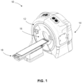
- a radiotherapy device 10 is provided. It will be appreciated that the radiotherapy device 10 can be used for a variety of applications, including, but not limited to, image-guided radiation treatment or therapy (IGRT).
- the radiotherapy device 10 can be used to carry out the imaging methods described more fully below.
- the radiotherapy device 10 includes a rotatable gantry system, referred to as gantry 12 supported by or otherwise housed in a support unit or housing 14.
- Gantry herein refers to a gantry system that comprises one or more gantries (e.g., ring or C-arm) capable of supporting one or more radiation sources and/or associated detectors as they rotate around a target.
- a first radiation source and its associated detector may be mounted to a first gantry of the gantry system and a second radiation source and its associated detector may be mounted to a second gantry of the gantry system.
- more than one radiation source and associated detector(s) may be mounted to the same gantry of the gantry system, including, for example, where the gantry system is comprised of only one gantry.
- Various combinations of gantries, radiation sources, and radiation detectors may be combined into a variety of gantry system configurations to image and/or treat the same volume within the same apparatus.
- kV and MV radiation sources can be mounted on the same or different gantries of the gantry system and selectively used for imaging and/or treatment as part of an IGRT system. If mounted to different gantries, the radiation sources are able to rotate independently, but are still able to simultaneously image the same (or nearly the same) volume.
- a rotatable ring gantry 12 may be capable of 10 revolutions per minute (rpm) or more (e.g., using fast slip ring rotation, including, e.g., up to 10 rpm, up to 20 rpm, up to 60 rpm, or more rpm).
- the rotatable gantry 12 defines a gantry bore 16 into and through which a patient can be moved and positioned for imaging and/or treatment.
- the rotatable gantry 12 is configured as a slip ring gantry to provide continuous rotation of an imaging radiation source and an associated radiation detector while providing sufficient bandwidth for the imaging data received by the detector.
- a slip-ring gantry can eliminate gantry rotations in alternating directions in order to wind and unwind cables carrying the power and signals associated with the device. As is discussed more fully below, such a configuration can allow for continuous helical (e.g., fan-beam, cone-beam, etc.) computed tomography, even when integrated into an IGRT system.
- a patient support 18 is positioned adjacent to the rotatable gantry 12 and configured to support a patient, typically in a horizontal position, for longitudinal movement into and within the rotatable gantry 12.
- the patient support 18 can move the patient, for example, in a direction perpendicular to the plane of rotation of the gantry 12 (along or parallel to the rotation axis of the gantry 12).
- the patient support 18 can be operatively coupled to a patient support controller for controlling movement of the patient and patient support 18.
- the patient support controller can be synchronized with the rotatable gantry 12 and sources of radiation mounted to the rotating gantry for rotation about a patient longitudinal axis in accordance with a commanded imaging and/or treatment plan.
- the patient support can also be moved in a limited range up and down, left and right once it is in the bore 16 to adjust the patient position for optimal treatment.
- the rotatable gantry 12 and patient support can be controlled such that the gantry 12 rotates in a "back-and-forth" manner (e.g., alternating clockwise rotation and counterclockwise rotation) around a patient supported on the patient support (as opposed to continuously, as is described above) as the support is controlled to move (at a constant or variable speed) relative to the rotatable gantry 12.
- the device 10 is capable of volume-based and planar-based imaging acquisitions.
- the device 10 may be used to acquire volume images and/or planar images and execute the associated processing methods described below.
- Non-continuous motion of the radiation source and/or patient support may be utilized, including in combination with the various embodiments of radiotherapy devices 10 described above.
- the scan speed of a patient on the support can be varied based on either how fast the gantry rotates or the speed at which the patient support moves in and out of the gantry.
- the radiotherapy device 10 includes a first source of radiation 20 coupled to or otherwise supported by the rotatable gantry 12.
- the first source of radiation 20 is configured as a source of therapeutic radiation, such as a high-energy source of radiation used for treatment of a tumor within a patient in a ROI.
- the source of therapeutic radiation can be a high-energy x-ray beam (e.g., megavoltage (MV) x-ray beam), and/or a high-energy particle beam (e.g., a beam of electrons, a beam of protons, or a beam of heavier ions, such as carbon) or another suitable form of high-energy radiation without departing from the scope of the disclosed technology.
- MV megavoltage
- the first source of radiation 20 comprises a mega-electron volt peak photon energy (MeV) of 1 MeV or greater.
- the high-energy x-ray beam has an average energy greater than 0.8 MeV.
- the high-energy x-ray beam has an average energy greater than 0.2 MeV.
- the high-energy x-ray beam has an average energy greater than 150keV.
- the first source of radiation 20 has a higher energy level (peak and/or average, etc.) than the second source of radiation 30.
- the imaging radiation source may be, for example, an x-ray generating source (including for CT) or any other way to produce photons with sufficient energy and flux (such as, e.g., a gamma-source (e.g., Cobalt-57, energy peak at 122 keV), an x-ray fluorescence source (such as fluorescence source through Pb k lines, two peaks @about 70 keV and @about 82 keV), etc.).
- a gamma-source e.g., Cobalt-57, energy peak at 122 keV
- an x-ray fluorescence source such as fluorescence source through Pb k lines, two peaks @about 70 keV and @about 82 keV
- References herein to x-ray, x-ray imaging, x-ray imaging source, etc. are exemplary for particular embodiments.
- Other imaging transmission sources can be used interchangeably in various other embodiments.
- the first source of radiation 20 can emit one or more beams of radiation (indicated generally by 22) toward a region-of-interest (ROI) within a patient supported on the patient support 18.
- the first source of radiation can emit one or more beams of radiation in accordance with a treatment plan.
- the treatment plan can include detailed parameters regarding source angular position, beam geometry, beam intensity, modulation, exposure, and the like.
- scan parameters or imaging parameters can be automatically calculated and or selectively adjusted relative to one or more parameters of at least a portion of the ROI in accordance with the disclosed technology, detailed below.
- the first source of radiation 20 is a LINAC producing therapeutic radiation (e.g., MV) and the imaging system comprises an independent second source of radiation 30 producing relatively low intensity and lower energy imaging radiation (e.g., kV).
- the first source of radiation 20 could be a radioisotope, such as, for example, Co-60, which can generally have energy >1 MeV.
- the first source of radiation 20 can emit one or more beams of radiation (indicated generally by 22) toward a region-of-interest (ROI) within a patient supported on the patient support 18 in accordance with a treatment plan.
- ROI region-of-interest
- FIGS. 1 and 2 depict a radiotherapy device 10 with a radiation source 20 mounted to a ring gantry 12
- other embodiments may include other types of rotatable imaging apparatuses, including, for example, C-arm gantries and robotic arm-based systems.
- a gantry rotates the imaging radiation source 30 around an axis passing through the isocenter.
- Gantry-based systems include C-arm gantries, in which the imaging radiation source 30 is mounted, in a cantilever-like manner, over and rotates about the axis passing through the isocenter.
- Gantry-based systems further include ring gantries, for example, rotatable gantry 12, having generally toroidal shapes in which the patient's body extends through a bore of the ring/toroid, and the imaging radiation source 30 is mounted on the perimeter of the ring and rotates about the axis passing through the isocenter.
- the gantry 12 rotates continuously.
- the gantry 12 utilizes a cable-based system that rotates and reverses repeatedly.
- First detector 24 can be coupled to or otherwise supported by the rotatable gantry 12 and positioned to receive radiation 22 from the first source of radiation 20.
- the first detector 24 can detect or otherwise measure the amount of radiation not attenuated and therefore infer what was in fact attenuated by the patient or associated patient ROI (by comparison to what was initially generated).
- the first detector 24 can detect or otherwise collect attenuation data from different angles as the first radiation source 20 rotates around and emits radiation toward the patient.
- the collected attenuation data can be processed and reconstructed into one or more images of the patient's body.
- the imaging system integrated within the radiotherapy device 10 can provide current images that are used to set up (e.g., align and/or register), plan, and/or guide the radiation delivery procedure (treatment). Typical set-up is accomplished by comparing current (in-treatment) images to pre-treatment image information (e.g., prior or otherwise previously-acquired image information).
- Pre-treatment image information may comprise, for example, CT data, CBCT data, magnetic resonance imaging (MRI) data, positron emission tomography (PET) data or 3D rotational angiography (3DRA) data, and/or any information obtained from these or other imaging modalities.
- the imaging system can track in-treatment patient, target, or ROI motion.
- CBCT digitally reconstructed radiographs
- DRRs digitally reconstructed radiographs
- CBCT can directly construct a 3D volumetric image from 2D projections of the target volume.
- CBCT has the ability to form a 3D image volume from a single gantry rotation about the target volume with a more isotropic spatial resolution.
- CBCT can utilize helical scan trajectories.
- the imaging system integrated within the radiotherapy device 10 includes a second source of radiation 30 coupled to or otherwise supported by the rotatable gantry 12.
- the second source of radiation 30 can be configured as a source of imaging radiation (e.g., kV) for high-quality in-treatment images (indicated generally as 32) having an energy level less than the first source 20 of therapeutic radiation.
- a second detector 34 (e.g., two-dimensional flat detector or curved detector) can be coupled to or otherwise supported by the rotatable gantry 12.
- the second detector 34 is positioned to receive radiation from the second source of radiation 30.
- the detector 34 can detect or otherwise measure the amount of radiation not attenuated and therefore infer what was in fact attenuated by the patient or associated patient ROI (by comparison to what was initially generated).
- the detector 34 can detect or otherwise collect attenuation data from different angles as the second radiation source 30 rotates around and emits radiation toward the patient.
- a collimator or beamformer assembly (indicated generally as 36) is positioned relative to the second source of radiation 30 to selectively control and adjust a shape of a radiation beam 32 emitted by the second radiation source 30 to selectively expose a portion or region of the active area of the second radiation detector 34.
- the collimator 36 can also control how the radiation beam 32 is positioned on the detector 34.
- the collimator 36 can have one degree/dimension of motion (e.g., to make a thinner or fatter slit).
- the collimator 36 could have two degrees/dimensions of motion (e.g., to make various sized rectangles).
- the collimator 36 may be capable of various other dynamically-controlled shapes, including, for example, parallelograms. All of these shapes may be dynamically adjusted during a scan.
- blocking portions of the collimator can be rotated and/or translated.
- the collimator/beamformer 36 may be configured in a variety of ways that allow it to adjust the shape of the radiation beam 32 emitted by the second source of radiation 30.
- the collimator 36 can be configured to include a set of jaws or other suitable members that define and selectively adjust the size of an aperture through which the radiation beam from the second source of radiation 30 may pass in a collimated manner.
- the collimator 36 can include an upper jaw and a lower jaw, where the upper and lower jaws are movable in different directions (e.g., parallel directions) to adjust the size of the aperture through which the radiation beam from the second source of radiation 30 passes, and also to adjust the beam 32 position relative to the patient to illuminate only the portion of the patient to be imaged for optimized imaging and minimized patient dose.
- a collimator can be configured as a multi-leaf collimator (MLC), which can include a plurality of interlaced leaves operable to move to one or more positions between a minimally-open or closed position and a maximally-open position. It will be appreciated that the leaves can be moved into desired positions to achieve a desired shape of a radiation beam being emitted by the radiation source.
- the MLC is capable of sub-millimeter targeting precision.
- the shape of the radiation beam 32 from the second source of radiation 30 can be changed during an image acquisition.
- the collimator 36 leaf positions and/or aperture width can be adjusted before or during a scan.
- the collimator 36 can be selectively controlled and dynamically adjusted during rotation of the second source of radiation 30 such that the radiation beam 32 has a shape with sufficient primary/shadow regions and is adjusted to include only an object of interest during imaging (e.g., the prostate).
- the shape of the radiation beam 32 being emitted by the second source of radiation 30 can be selectively controlled during or after a scan, depending on the desired image acquisition, which may be based on imaging and/or therapeutic feedback, as discussed in more detail below.
- the first source of radiation 20 can include or otherwise be associated with a beamformer or collimator.
- the collimator/beamformer associated with the first source of radiation 20 can be configured in a number of ways, similar to the collimator 36 associated with the second source of radiation 30.
- the collimator assembly 36 can be controlled to adjust the shape of the radiation beam 32 emitted by the second source of radiation 30 in a number of geometries, including, but not limited to, a fan beam, thick fan beam, or cone beam having a beam thickness (width) as low as one detector row width or including multiple detector rows, which may be only a portion of the detector's active area.
- the thickness of the beam may expose several centimeters of a larger detector active area. For example, 3-4 centimeters (measured in the longitudinal direction in the detector plane) of a 5-6-centimeter detector may be selectively exposed to the imaging radiation 32.
- various other exposed and active area sizes or ratios of exposed-to-active detector area may be suitable in other embodiments.
- the radiotherapy device 10 has been described above as including a first source of radiation 20, a second source of radiation 30, a first radiation detector 24 positioned to receive radiation from the first source of radiation 20 and a second radiation detector 34 positioned to receive radiation from the second radiation source 30. It will be appreciated, however, that the radiotherapy device 10 can include a first source of radiation 20 (e.g., a source of therapeutic radiation), a second source of radiation 30 (e.g., a kV radiation source) and only a radiation detector 34 positioned to receive radiation from the second source of radiation 30 without departing from the scope of the disclosed technology.
- a first source of radiation 20 e.g., a source of therapeutic radiation
- a second source of radiation 30 e.g., a kV radiation source
- the radiation source 20 may be mounted, configured, and/or moved into the same plane or a different plane (offset) than the radiation source 30.
- scatter caused by simultaneous activation of the radiation sources 20, 30 may be incrementally reduced by offsetting the radiation planes.
- scatter can be avoided by interleaving the activations. For example, with simultaneous multimodal imaging, the acquisitions can be concurrent, without having concurrent individual pulses. In another embodiment, use of shadow-based scatter correction can be used, for example, to address the problem of MV scatter on a kV detector.
- apparatus 10 can provide images that are used to set up (e.g., align and/or register), plan, and/or guide a radiation delivery procedure (treatment). Typical set-up is accomplished by comparing current (in-treatment) images to pre-treatment image information.
- Pre-treatment image information may comprise, for example, CT data, CBCT data, MRI data, PET data or 3D rotational angiography (3DRA) data, and/or any information obtained from these or other imaging modalities.
- the device 10 can track in-treatment patient, target, or ROI motion.
- a reconstruction processor 40 can be operatively coupled to the first detector 24 and/or second detector 34.
- the reconstruction processor 40 is configured to generate patient images based on radiation received by detectors 24, 34 from the radiation sources 20, 30.
- the reconstruction processor 40 may comprise a processor, memory, software, logic or other components and can implement one or more routines or steps to utilize scanning data and parameters to create patient images. It will be appreciated that the reconstruction processor 40 can be configured to be used to carry out the methods described more fully below .
- the apparatus 10 can also include a memory 44 suitable for storing information, including, but not limited to, processing and reconstruction algorithms and software, imaging parameters, image data from a prior or otherwise previously-acquired image (e.g., a planning image), treatment plans, and the like.
- the radiotherapy device 10 can include an operator/user interface 48, where an operator of the radiotherapy device 10 can interact with or otherwise control the radiotherapy device 10 to provide input relating to scan or imaging parameters and the like.
- the operator interface 48 can include any suitable input devices, such as a keyboard, mouse, voice-activated controller, or the like.
- the radiotherapy device 10 can also include a display 52 or other human-readable element to provide output to the operator of the radiotherapy device 10.
- the display 52 can allow the operator to observe reconstructed patient images and other information, such as imaging or scan parameters, related to operation of the radiotherapy device 10.
- collimator assembly 36 positioned relative to the second source of radiation 30 can be configured to provide dynamic collimation of a radiation beam being emitted by the second radiation source 30
- the collimator assembly 36 can be controlled such that the beam 32 from the second radiation source 30 covers as much or as little of the second detector 34 based on the particular imaging task being carried out.
- the collimator 36 can be selectively controlled to provide a fan beam having a fan thickness from a single detector row, which could be sub-millimeter, up to several centimeters, including, for example, a beam thickness of 3-4 centimeters (measured in the longitudinal direction in the detector plane).
- a beam configuration can be used in a continuous, helical fan-beam imaging mode in accordance with aspects of the disclosed technology. In other embodiments, circular imaging modes may be used, including with a larger fan beam or cone beam thickness.
- the collimator 36 can be selectively controlled to provide a beam having a thickness of about one centimeter.
- the collimator 36 can be selectively controlled to provide a beam having a thickness of more than one centimeter or several centimeters, including, for example, between about two centimeters and about four centimeters.
- the collimator 36 can be selectively controlled to provide a beam 32 having a thickness between about fifteen centimeters and about thirty centimeters.
- the collimator 36 can be selectively controlled to provide a beam 32 having a thickness between about thirty-five centimeters and about forty centimeters.
- the system and beam geometry can be controlled to yield beams that are thin (e.g., single row), thick (e.g., multi-row), or cone-shaped.
- the radiotherapy device 10 includes a controller (indicated generally as 60) operatively coupled to one or more components of the radiotherapy system 10.
- the controller 60 controls the overall functioning and operation of the radiotherapy device 10, including providing power and timing signals to the first radiation source 20 and/or the second radiation source 30 and a gantry motor controller that controls rotational speed and position of the rotatable gantry 12.
- the controller 60 can encompass one or more of the following: a patient support controller, a gantry controller, a controller coupled to the first radiation source 20 and/or the second radiation source 30, a collimator assembly controller, a controller coupled to the first detector 24 and/or the second detector 34, and the like.
- controller 60 is a system controller that can control other components, devices, and/or controllers.
- the reconstruction processor 40, the operator interface 48, the display 52, the controller 60 and/or other components may be combined into one or more components or devices.
- the radiotherapy system 10 may include various components, logic, and software.
- the controller 60 comprises a processor, a memory, and software.
- a radiotherapy system (such as, for example, radiotherapy system 10 shown in FIGS. 1 and 2 ) can include various other devices and components (e.g., gantries, radiation sources, collimators, detectors, controllers, power sources, patient supports, among others) that can implement one or more routines or steps related to imaging and/or IGRT for a specific application, wherein a routine can include imaging, image-based pre-delivery steps, and/or treatment delivery, including respective device settings, configurations, and/or positions (e.g., paths/trajectories) which may be stored in memory.
- routines include processes and/or algorithms associated with data and image processing, including, for example, the processes described below.
- the controller(s) can directly or indirectly control one or more devices and/or components in accordance with one or more routines or processes stored in memory.
- An example of direct control is the setting of various radiation source or collimator parameters (power, speed, position, timing, modulation, etc.) associated with imaging or treatment.
- An example of indirect control is the communication of position, path, speed, etc. to a patient support controller or other peripheral device.
- the hierarchy of the various controllers that may be associated with a radiotherapy device 10 can be arranged in any suitable manner to communicate the appropriate commands and/or information to the desired devices and components.
- the systems and methods may be implemented with other computer system configurations.
- the illustrated aspects of the invention may be practiced in distributed computing environments where certain tasks are performed by local or remote processing devices that are linked through a communications network.
- the reconstruction processor 40 may be associated with a separate system.
- program modules may be located in both local and remote memory storage devices.
- a remote database, a local database, a cloud-computing platform, a cloud database, or a combination thereof can be utilized with radiotherapy device 10.
- Radiotherapy device 10 can utilize an exemplary environment for implementing various aspects of the invention including a computer, wherein the computer includes the controller 60 (e.g., including a processor and a memory, which may be memory 44) and a system bus.
- the system bus can couple system components including, but not limited to the memory to the processor, and can communicate with other systems, controllers, components, devices, and processors.
- Memory can include read only memory (ROM), random access memory (RAM), hard drives, flash drives, and any other form of computer readable media.
- Memory can store various software and data, including routines and parameters, which may comprise, for example, a treatment plan.
- the first source of radiation 20 and/or second source of radiation 30 can be operatively coupled to a controller 60 configured to control the relative operation of the first source of radiation 20 and the second source of radiation 30.
- the second source of radiation 30 can be controlled and operated simultaneously with the first source of the radiation 20.
- the second source of radiation 30 can be controlled and operated sequentially with the first source of radiation 20, depending on the particular treatment and imaging plan being implemented.
- the second detector 34 can take on a number of configurations without departing from the scope of the disclosed technology. As illustrated in FIG. 2 , the second detector 34 can be configured as a flat-panel detector (e.g., a multi-row flat panel detector). In accordance with another exemplary embodiment, the second detector 34 can be configured as a curved detector.
- the second source of radiation 30 and the associated second detector 34 are positioned approximately 180 degrees from one another about the rotating gantry. It will be appreciated that the second source of radiation 30 and the associated second detector 34 can be positioned in different orientations other than 180 degrees offset. For example, the second radiation source and the associated second detector can be positioned relative to one another to achieve a half-fan CT acquisition. In another exemplary embodiment second detector need not be directly 180 degrees from second radiation 30 source as shown in Figure 2 but can be offset to either side of the location shown.
- the collimator assembly 36 positioned relative to or otherwise associated with the second source of radiation 30 can be selectively controlled to control the shape of the radiation beam 32 emitted by the second radiation source 30 to selectively expose part or all of the second radiation detector 34.
- the beam from the second source of radiation can be collimated or otherwise controlled to provide a fan or cone beam of imaging radiation. It will be appreciated that the size and geometry of the beam can be controlled based on the particular desired imaging application.
- the collimator assembly 36 can be selectively controlled such that the radiation beam 32 emitted by the second source of radiation is a fan beam, having a fan beam thickness greater than and down to about one centimeter.
- the geometry of the radiation beam 32 being emitted by the second radiation source can be changed during or after a scan, depending on the desired image acquisition, which may be based on imaging and/or therapeutic feedback.
- the second source of radiation 30 and the second detector 34 positioned to receive radiation from the second source of radiation 30 can be configured to provide continuous rotation around the patient during an imaging scan. Further, synchronizing the motion and exposure of the second radiation source 30 with the longitudinal motion of the patient support can provide a continuous helical fan beam acquisition of a patient image during a procedure.
- the following flow charts and block diagrams illustrate exemplary configurations and methodologies associated with CT and/or IGRT in accordance with the systems described above.
- the exemplary methodologies may be carried out in logic, software, hardware, or combinations thereof which may be comprised as parts of controller 60.
- the procedures and methods are presented in an order, the blocks may be performed in different orders, including series and/or parallel.
- the first and second radiation sources 20, 30 may be activated sequentially and/or simultaneously.
- the steps below, including imaging, image processing, image-based pre-delivery steps, and treatment delivery although shown sequentially, may be executed simultaneously, including in real-time. Further, additional steps or fewer steps may be used.
- imaging methods using the disclosed technology and described more fully below can be carried out using imaging from one or both of the first source of radiation 20 together with the first radiation detector 24 and the second source of radiation 30 together with the second radiation detector 34.
- the disclosed technology allows for control of at least the second radiation beam 32, such as via the controller 60, to modulate scan parameters of the second radiation beam 32 based on one or more parameters of the ROI (shown generally at 70).
- scan parameters relative to one or both of the first radiation beam 22 or the second radiation beam 32 may be modulated based on one or more parameters of the ROI.
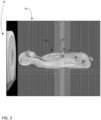
- an exemplary ROI 70 may include the pancreas 72 and the liver 74.
- these organs are viewable in a slice 76 (e.g., a sagittal slice) of a scan image.
- the slice 76 illustrates one exemplary user-selectable slice from a planning image (or other prior or previously-acquired image, including, but not limited to, an image acquired during an IGRT procedure), with the particular exemplary illustrated view being parallel to the patient's sagittal plane.
- a ROI for a patient 78 may include a volume of interest (VOI), such as a volume to target, which in this case may be the pancreas 72.
- VOI volume of interest
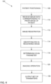
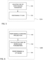
- performing the imaging operation may include performing a forward projection with respect to the patient at block 140.
- the forward projection uses the input image, which may be an input planning image, and also uses the determined scan parameter of block 116, to provide an image of the patient.
- the forward projection is performed for at least one view angle of the ROI, but alternatively may be performed for a plurality of view angles of the ROI to form a "curve" of parameter data for the ROI.
- Tube current is adjustable for optimizing gray level and/or limiting quantum noise.
- a gray level may be adjusted, such as to limit or altogether avoid saturation or photon starvation.
- Binning can allow charges from adjacent pixels to be combined, such as to optimize data streaming speed and/or noise.
- Focal spot may be adjustable according to varying of one or more of the tube current, tube potential and scan speed.
- Other parameters can include beam width (e.g., dynamically collimated from view to view), helical pitch (e.g., dynamic helical pitch from view to view), and detector readout section size (e.g., dynamic selection of detector readout section from view to view).
- a set of one or more scan parameters (e.g., an optimized set of parameters) is output at block 150.
- the set includes at least one determined or calculated scan parameter, referring to block 116 and 130/142.
- the set includes each of the scan parameters determined and/or calculated at each of blocks 116 and 130/142.
- the set includes at least one view-angle dependent modulated scan parameter based on the ROI or portion of the ROI, such as based on one or more parameters of the ROI or portion of the ROI.
- one or more method embodiments may include an additional step of patient positioning at block 108. While shown as the initial step, block 108 may be otherwise positioned before block 120.
- the patient subject to an image acquisition or IGRT is positioned on a patient support/couch, such as the patient support 18, that is configured for longitudinal movement within a rotatable gantry, such as the rotatable gantry 12.
- the rotatable gantry will be coupled to a source of radiation and to a detector positioned to receive radiation from the source of radiation.
- the source of radiation may be a kV source configured to emit a fan beam, such as the second source of radiation 30.
- the disclosed technology may allow for recognition of one or more benefits associated with a radiation delivery device and method using ROI guidance for controlling exposure of a beam from a source of imaging radiation of the radiation delivery device based on one or more parameters of a ROI of a patient.
- these benefits may include, but are not limited to, one or more of reduced scan time, targeted dosing, uniform dosing relative and reduced radiation exposure to the patient or ROI of the patient and/or reduced x-ray scatter with improved soft tissue contrast.
- the reduced radiation exposure will prevent damage to sensitive organs such as eyes and other organs not involved with the ROI.
- Another benefit of the disclosed technology is that an x-ray dosage can be optimized to enhance image quality to obtain better quality and more precise images for treatment scans.
- a device 10 is provided that is configurable to provide controlled exposure of a beam 22, 32 from a source of imaging radiation 20, 30 of a radiation-delivery device 10 based on one or more parameters of a ROI of a patient.
- the above-described radiation-delivery technology can generate low-energy (e.g., kV) images that can be used in a variety of ways without departing from the scope of the disclosed technology.
- images generated by the radiotherapy device can be used to align a patient prior to treatment.
- images generated by the radiotherapy device can be used to calculate imaging dose.
- images generated by the radiotherapy device can be used to calculate treatment dose.
- a method of scanning parameter optimization which method may be useful with IGRT, allows for controlling exposure of a beam from a source of imaging radiation of a radiation-delivery device based on one or more parameters of a ROI of a patient.
- the one or more parameters of the ROI may include a dimension, outer contour, density, location relative to an outlet of the beam, location relative to isocenter, and relative location with respect to the patient's entire body.
- Exposure of the patient to the beam may be varied via modulation of one or more scanning parameters for controlling an aspect of the beam to provide for targeted and or reduced radiation exposure of the patient or portion of the patient.
- the modulation may be varied depending on a view angle of the ROI from a portion of the radiation-delivery device, which view angle may vary upon movement of the ROI and/or a radiation delivery portion of the device relative to one another.
- FIG. 7 is a flow chart depicting an exemplary method 1000 of IGRT using a radiotherapy device (e.g., radiotherapy device 10).
- Prior image data 1005 of the patient is available for use (e.g., a prior image, which may be a previously-acquired planning image, including a prior CT image, as discussed above).
- Prior data 1005 can also include treatment plans, phantom information, models, a priori information, etc.
- prior image data 1005 is generated by the same radiotherapy device, but at an earlier time.
- imaging of the patient is performed using a source of low-energy radiation (e.g., kV radiation from second radiation source 30).
- a source of low-energy radiation e.g., kV radiation from second radiation source 30.
- Step 1010 can produce image(s) or imaging data 1015 (e.g., input data that includes the primary data acquired from the available source trajectory, as discussed above).
- image quality may be adjusted to optimize a balance between image quality/resolution and dosage. In other words, not all images need to be of the highest quality or image quality may be adjusted to optimize or trade off a balance between image quality and image acquisition time.
- Imaging step 1010 also includes image processing to generate patient images based on the imaging data (e.g., in accordance with method100 described above). Although image processing step 1020 is shown as part of imaging step 1010, in some embodiments image processing step 1020 is a separate step, including where image processing is executed by separate devices.
- step 1030 one or more image-based pre-delivery steps, discussed below, are performed based at least in part on the imaging data 1015 from step 1010.
- step 1030 can include determining various parameters associated with the therapeutic treatment and (subsequent) imaging planning.
- Step 1030 also may include the data optimization process based on an ROI discussed above with respect to Figures 3-6 .
- image-based pre-delivery steps (1030) may require more imaging (1010) before treatment delivery (1040).
- Step 1030 can include adapting a treatment plan based on the imaging data 1015 as part of an adaptive radiotherapy routine.
- image-based pre-delivery steps 1030 may include real-time treatment planning.
- Embodiments may also include simultaneous, overlapping, and/or alternating activation of the imaging and therapeutic radiation source (not part of the claimed invention).
- Real-time treatment planning may involve any or all of these types of imaging and therapeutic radiation activation techniques (simultaneous, overlapping, and/or alternating).
- Step 1040 therapeutic treatment delivery is performed using a source of high-energy radiation (e.g., MV radiation from first radiation source 20).
- Step 1040 delivers a treatment dose 1045 to the patient according to the treatment plan.
- the IGRT method 1000 may include returning to step 1010 for additional imaging at various intervals, followed by image-based pre-delivery steps (1030) and/or treatment delivery (1040) as required.
- the imaging data 1015 may be produced and utilized during IGRT using one radiotherapy device 10 that is capable of adaptive therapy.
- steps 1010, 1020, 1030, and/or 1040 may be executed simultaneously, overlapping, and/or alternating.
- IGRT can include at least two general goals: (i) to deliver a highly conformal dose distribution to the target volume; and (ii) to deliver treatment beams with high accuracy throughout every treatment fraction.
- a third goal can be to accomplish the two general goals in as little time per fraction as possible.
- Delivering treatment beams accurately requires the ability to identify and/or track the location of the target volume intrafraction with high-quality images.
- the ability to increase delivery speed requires the ability to accurately, precisely, and quickly move the radiation source according to the treatment plan.
- FIG. 8 is a block diagram 1100 depicting exemplary image-based pre-delivery steps/options that may be associated with step 1030 above.
- the above-described radiotherapy device e.g., radiotherapy device 10
- images 1015 generated by the radiotherapy device can be used to align a patient prior to treatment (1110).
- Patient alignment can include correlating or registering the current imaging data 1015 with imaging data associated with earlier pre-treatment scans and/or plans, including the treatment plan.
- Patient alignment can also include feedback on the physical position of the patient relative to the radiation source to verify whether the patient is physically within the range of the delivery system. If necessary, the patient can be adjusted accordingly.
- patient alignment imaging may purposely be of lesser quality to minimize dosage but provide adequate alignment information.
- the imaging data 1015 shows that the target volume or ROI is the same as when the treatment plan was developed, then the treatment plan can be confirmed. However, if the target volume or ROI is not the same, re-planning of the therapeutic treatment may be necessary. In the case of re-planning, because of the high quality of the imaging data 1015 (generated by the radiotherapy device 10 at step 1010), the imaging data 1015 may be used for treatment planning or re-planning (e.g., generating a new or modified treatment plan). In this manner, pre-treatment CT imaging via a different device is not necessary. In some embodiments, confirming and/or re-planning may be an ongoing procedure before and/or after various treatments.
- images generated by the radiotherapy device 10 can be used to calculate imaging dose (1130), which may be used for ongoing determinations of total dose to the patient and/or for subsequent imaging planning.
- Step 1130 also may include the data optimization method based on an ROI discussed above with respect to Figures 3-6 .
- the quality of subsequent imaging may also be determined as part of the treatment planning, for example, to balance quality and dosage.
- images generated by the radiotherapy device 10 can be used to calculate treatment dose (1140), which may be used for ongoing determinations of total dose to the patient and/or may be included as part of treatment planning or re-planning.
- calculate treatment dose (1140) can be a step by itself and/or can be part of adaptive therapy monitoring (1170) and/or treatment planning (1120).
- the image-based pre-delivery steps (1030) can be performed automatically and/or manually with human involvement.
- FIG. 9 is a block diagram 1200 depicting exemplary data sources that may be utilized during imaging (1010) and/or subsequent treatment planning (1020), in addition to the prior data 1005.
- Detector data 1210 represents the data received by the image radiation detector 34.
- the projection data 1220 is the data generated by the radiation incident in the collimated beam area, which may be referred to as the primary region.
- the penumbra data 1230 is the data generated by the radiation incident in the penumbra region or area.
- the scatter data 1240 is the data generated by the radiation incident in a peripheral or scatter (only) region or area.
- the penumbra data 1230 and/or the scatter data 1240 may be utilized to improve the quality of the images generated by the imaging step 1010.
- the penumbra data 1230 and/or the scatter data 1240 may be combined with the projection data 1220 and/or analyzed in view of the applicable imaging settings 1250, treatment settings 1260 (e.g., if simultaneous imaging and treatment radiation), and any other data 1270 associated with the radiotherapy device 10 at the time of the data collection at the imaging detector 34, including as discussed above.
- the data may be used for the treatment planning step 1020.
Landscapes
- Health & Medical Sciences (AREA)
- Life Sciences & Earth Sciences (AREA)
- Engineering & Computer Science (AREA)
- Medical Informatics (AREA)
- Biomedical Technology (AREA)
- Nuclear Medicine, Radiotherapy & Molecular Imaging (AREA)
- Public Health (AREA)
- Animal Behavior & Ethology (AREA)
- General Health & Medical Sciences (AREA)
- Veterinary Medicine (AREA)
- Pathology (AREA)
- Radiology & Medical Imaging (AREA)
- Physics & Mathematics (AREA)
- Surgery (AREA)
- Heart & Thoracic Surgery (AREA)
- Molecular Biology (AREA)
- Biophysics (AREA)
- High Energy & Nuclear Physics (AREA)
- Optics & Photonics (AREA)
- Computer Vision & Pattern Recognition (AREA)
- Theoretical Computer Science (AREA)
- Pulmonology (AREA)
- Human Computer Interaction (AREA)
- General Physics & Mathematics (AREA)
- Dentistry (AREA)
- Oral & Maxillofacial Surgery (AREA)
- Radiation-Therapy Devices (AREA)
- Apparatus For Radiation Diagnosis (AREA)
- Toxicology (AREA)
- Automation & Control Theory (AREA)
- Robotics (AREA)
- Physiology (AREA)
Priority Applications (1)
| Application Number | Priority Date | Filing Date | Title |
|---|---|---|---|
| EP25179152.1A EP4603141A3 (en) | 2018-11-30 | 2019-11-25 | Optimized scanning methods and tomography system using region of interest data |
Applications Claiming Priority (12)
| Application Number | Priority Date | Filing Date | Title |
|---|---|---|---|
| US201862773712P | 2018-11-30 | 2018-11-30 | |
| US201862773700P | 2018-11-30 | 2018-11-30 | |
| US201962796831P | 2019-01-25 | 2019-01-25 | |
| US201962800287P | 2019-02-01 | 2019-02-01 | |
| US201962801260P | 2019-02-05 | 2019-02-05 | |
| US201962813335P | 2019-03-04 | 2019-03-04 | |
| US201962821116P | 2019-03-20 | 2019-03-20 | |
| US201962836357P | 2019-04-19 | 2019-04-19 | |
| US201962836352P | 2019-04-19 | 2019-04-19 | |
| US201962843796P | 2019-05-06 | 2019-05-06 | |
| US201962878364P | 2019-07-25 | 2019-07-25 | |
| PCT/US2019/063078 WO2020112677A2 (en) | 2018-11-30 | 2019-11-25 | Optimized scanning methods and tomography system using region of interest data |
Related Child Applications (2)
| Application Number | Title | Priority Date | Filing Date |
|---|---|---|---|
| EP25179152.1A Division-Into EP4603141A3 (en) | 2018-11-30 | 2019-11-25 | Optimized scanning methods and tomography system using region of interest data |
| EP25179152.1A Division EP4603141A3 (en) | 2018-11-30 | 2019-11-25 | Optimized scanning methods and tomography system using region of interest data |
Publications (2)
| Publication Number | Publication Date |
|---|---|
| EP3886711A2 EP3886711A2 (en) | 2021-10-06 |
| EP3886711B1 true EP3886711B1 (en) | 2025-07-02 |
Family
ID=68848544
Family Applications (13)
| Application Number | Title | Priority Date | Filing Date |
|---|---|---|---|
| EP19888415.7A Active EP3886711B1 (en) | 2018-11-30 | 2019-11-25 | Optimized scanning methods and tomography system using region of interest data |
| EP19824063.2A Active EP3886706B1 (en) | 2018-11-30 | 2019-11-25 | Method and apparatus for image reconstruction and correction using inter-fractional information |
| EP19824058.2A Active EP3886708B1 (en) | 2018-11-30 | 2019-11-25 | Method and apparatus for scatter estimation in cone-beam computed tomography |
| EP19824057.4A Active EP3886710B1 (en) | 2018-11-30 | 2019-11-25 | Computed tomography system and method for image improvement using prior image |
| EP19818497.0A Pending EP3886707A1 (en) | 2018-11-30 | 2019-11-25 | Helical cone-beam computed tomography imaging with an off-centered detector |
| EP19824055.8A Active EP3886703B1 (en) | 2018-11-30 | 2019-11-25 | Method and apparatus for improving scatter estimation and correction in imaging |
| EP25179152.1A Pending EP4603141A3 (en) | 2018-11-30 | 2019-11-25 | Optimized scanning methods and tomography system using region of interest data |
| EP19824061.6A Active EP3886705B1 (en) | 2018-11-30 | 2019-11-25 | Apparatus and methods for scalable field of view imaging using a multi-source system |
| EP19824062.4A Active EP3886709B1 (en) | 2018-11-30 | 2019-11-25 | Multi-pass computed tomography scans for improved workflow and performance |
| EP19824056.6A Pending EP3886979A1 (en) | 2018-11-30 | 2019-11-25 | Integrated helical fan-beam computed tomography in image-guided radiation treatment device |
| EP23215814.7A Active EP4310864B1 (en) | 2018-11-30 | 2019-11-25 | Method and apparatus for improving scatter estimation and correction in imaging |
| EP19824059.0A Active EP3886714B1 (en) | 2018-11-30 | 2019-11-25 | Asymmetric scatter fitting for optimal panel readout in cone-beam computed tomography |
| EP19824060.8A Active EP3886704B1 (en) | 2018-11-30 | 2019-11-25 | Multimodal radiation apparatus and methods |
Family Applications After (12)
| Application Number | Title | Priority Date | Filing Date |
|---|---|---|---|
| EP19824063.2A Active EP3886706B1 (en) | 2018-11-30 | 2019-11-25 | Method and apparatus for image reconstruction and correction using inter-fractional information |
| EP19824058.2A Active EP3886708B1 (en) | 2018-11-30 | 2019-11-25 | Method and apparatus for scatter estimation in cone-beam computed tomography |
| EP19824057.4A Active EP3886710B1 (en) | 2018-11-30 | 2019-11-25 | Computed tomography system and method for image improvement using prior image |
| EP19818497.0A Pending EP3886707A1 (en) | 2018-11-30 | 2019-11-25 | Helical cone-beam computed tomography imaging with an off-centered detector |
| EP19824055.8A Active EP3886703B1 (en) | 2018-11-30 | 2019-11-25 | Method and apparatus for improving scatter estimation and correction in imaging |
| EP25179152.1A Pending EP4603141A3 (en) | 2018-11-30 | 2019-11-25 | Optimized scanning methods and tomography system using region of interest data |
| EP19824061.6A Active EP3886705B1 (en) | 2018-11-30 | 2019-11-25 | Apparatus and methods for scalable field of view imaging using a multi-source system |
| EP19824062.4A Active EP3886709B1 (en) | 2018-11-30 | 2019-11-25 | Multi-pass computed tomography scans for improved workflow and performance |
| EP19824056.6A Pending EP3886979A1 (en) | 2018-11-30 | 2019-11-25 | Integrated helical fan-beam computed tomography in image-guided radiation treatment device |
| EP23215814.7A Active EP4310864B1 (en) | 2018-11-30 | 2019-11-25 | Method and apparatus for improving scatter estimation and correction in imaging |
| EP19824059.0A Active EP3886714B1 (en) | 2018-11-30 | 2019-11-25 | Asymmetric scatter fitting for optimal panel readout in cone-beam computed tomography |
| EP19824060.8A Active EP3886704B1 (en) | 2018-11-30 | 2019-11-25 | Multimodal radiation apparatus and methods |
Country Status (5)
| Country | Link |
|---|---|
| US (12) | US11375970B2 (cg-RX-API-DMAC7.html) |
| EP (13) | EP3886711B1 (cg-RX-API-DMAC7.html) |
| JP (13) | JP7564098B2 (cg-RX-API-DMAC7.html) |
| CN (11) | CN113164144A (cg-RX-API-DMAC7.html) |
| WO (11) | WO2020112674A1 (cg-RX-API-DMAC7.html) |
Families Citing this family (98)
| Publication number | Priority date | Publication date | Assignee | Title |
|---|---|---|---|---|
| US10737479B2 (en) | 2017-01-12 | 2020-08-11 | Global Filtration Systems | Method of making three-dimensional objects using both continuous and discontinuous solidification |
| US10688320B2 (en) | 2017-05-30 | 2020-06-23 | Reflexion Medical, Inc. | Methods for real-time image guided radiation therapy |
| EP4344736A3 (en) | 2017-06-22 | 2024-07-03 | RefleXion Medical, Inc. | Methods for calculating bounded dose-volume histograms (dvh) for evaluating a treatment plan |
| CN117761751A (zh) | 2017-07-26 | 2024-03-26 | 反射医疗公司 | 放射治疗的图形表示 |
| CN111372653B (zh) | 2017-09-22 | 2022-06-17 | 反射医疗公司 | 用于穿梭模式放射输送的系统和方法 |
| CN119701229A (zh) | 2018-02-13 | 2025-03-28 | 反射医疗公司 | 光束站治疗计划和放射输送方法 |
| WO2019213743A1 (en) * | 2018-05-07 | 2019-11-14 | Dalhousie University | Systems and methods for planning, controlling and/or delivering radiotherapy and radiosurgery using combined optimization of dynamic axes (coda) |
| US12285182B2 (en) | 2018-10-10 | 2025-04-29 | Innova Vascular, Inc. | Devices and methods for removing an embolus |
| CA3121277A1 (en) * | 2018-11-28 | 2020-06-04 | Provincial Health Services Authority | Motion synchronized arc radiotherapy |
| JP7564098B2 (ja) | 2018-11-30 | 2024-10-08 | アキュレイ インコーポレイテッド | 画像誘導放射線治療装置内に統合されるヘリカルファンビームコンピュータ断層撮影 |
| WO2020150505A1 (en) * | 2019-01-16 | 2020-07-23 | Reflexion Medical, Inc. | Methods for setup corrections in radiation therapy |
| US10867375B2 (en) * | 2019-01-30 | 2020-12-15 | Siemens Healthcare Gmbh | Forecasting images for image processing |
| JP1650139S (cg-RX-API-DMAC7.html) * | 2019-04-05 | 2020-01-20 | ||
| USD940868S1 (en) * | 2019-05-06 | 2022-01-11 | Siemens Healthcare Gmbh | Electromedical device |
| EP4732899A3 (en) | 2019-07-12 | 2026-05-20 | RefleXion Medical, Inc. | MULTI-TARGET TREATMENT PLANNING AND ADMINISTRATION AND VIRTUAL LOCALIZATION FOR RADIOTHERAPY |
| USD940869S1 (en) * | 2019-08-30 | 2022-01-11 | Siemens Healthcare Gmbh | Medical imaging apparatus |
| CN114727791A (zh) * | 2019-10-11 | 2022-07-08 | 得克萨斯系统大学评议会 | 用于复合材料的可变变焦x射线计算机断层成像方法 |
| USD931463S1 (en) * | 2019-11-22 | 2021-09-21 | Siemens Healthcare Gmbh | Medical imaging apparatus |
| US11139570B2 (en) * | 2019-12-10 | 2021-10-05 | Rockwell Collins, Inc. | Ultra-wideband circular beamformer |
| US11241211B2 (en) * | 2020-03-12 | 2022-02-08 | Canon Medical Systems Corporation | Method and apparatus for singles spectrum estimation and for dead-time correction in positron emission tomography (PET) |
| US11276209B2 (en) * | 2020-04-28 | 2022-03-15 | Canon Medical Systems Corporation | Method and apparatus for scatter estimation in positron emission tomography |
| GB2598273B (en) * | 2020-05-01 | 2023-03-29 | Elekta ltd | Patient positioning for radiotherapy treatment |
| CN111784664B (zh) * | 2020-06-30 | 2021-07-20 | 广州柏视医疗科技有限公司 | 肿瘤淋巴结分布图谱生成方法 |
| GB2596575B (en) * | 2020-07-01 | 2023-04-19 | Elekta ltd | An imaging system for a radiotherapy device |
| US11666293B2 (en) * | 2020-07-03 | 2023-06-06 | The Brigham And Women's Hospital, Inc. | Extended field-of-view x-ray imaging using multiple x-ray sources and one or more laterally offset x-ray detectors |
| CN111773561B (zh) * | 2020-07-10 | 2022-04-08 | 苏州雷泰医疗科技有限公司 | 平板探测器位置偏移量检测方法及放射治疗装置 |
| US11464464B2 (en) * | 2020-07-24 | 2022-10-11 | International Business Machines Corporation | Internal and external proximate scanning |
| CN114365196B (zh) * | 2020-08-04 | 2025-07-18 | 万睿视影像有限公司 | 估计来自未知源的背景辐射 |
| CN116056757A (zh) | 2020-08-07 | 2023-05-02 | 反射医疗公司 | 多传感器引导的放射疗法 |
| US20220079534A1 (en) * | 2020-09-11 | 2022-03-17 | Varian Medical Systems International Ag | Apparatus for fast cone-beam tomography and extended sad imaging in radiation therapy |
| WO2022056435A1 (en) * | 2020-09-14 | 2022-03-17 | EKTO VR, Inc. | System and method of robotic virtual reality footwear |
| US20220087632A1 (en) * | 2020-09-24 | 2022-03-24 | Our United Corporation | Imaging system, imaging method and radiotherapy system |
| CN116234611A (zh) * | 2020-09-30 | 2023-06-06 | 西安大医集团股份有限公司 | 患者位置显示方法、系统、电子设备及存储介质 |
| WO2022098794A1 (en) | 2020-11-04 | 2022-05-12 | Reflexion Medical, Inc. | Methods for tumor tracking |
| USD1001284S1 (en) | 2020-11-17 | 2023-10-10 | Siemens Healthcare Gmbh | Medical imaging device |
| US11430633B2 (en) | 2020-12-29 | 2022-08-30 | Fei Company | Illumination apertures for extended sample lifetimes in helical tomography |
| CN117083107A (zh) * | 2021-01-26 | 2023-11-17 | 阿朵思有限责任公司 | 用于放射疗法系统的剂量引导和最终递送辐射剂量的重复估计的系统和方法 |
| CN114820833B (zh) * | 2021-01-27 | 2025-10-03 | 上海西门子医疗器械有限公司 | 预测x射线的散射信号的方法、装置及校正散射束的方法 |
| EP4298433A4 (en) * | 2021-02-23 | 2025-01-08 | Rapiscan Systems, Inc. | SYSTEMS AND METHODS FOR ELIMINATING CROSSTALK SIGNALS IN SCANNING SYSTEMS HAVING MULTIPLE X-RAY SOURCES |
| CN113081013B (zh) * | 2021-03-19 | 2024-04-23 | 东软医疗系统股份有限公司 | 定位片扫描方法、装置及系统 |
| ES3036379T3 (en) * | 2021-04-05 | 2025-09-18 | Carestream Health Inc | Personalized critical care imaging |
| EP4079227B1 (en) * | 2021-04-23 | 2025-06-04 | Siemens Healthineers AG | Adaption of a medical imaging process to an individual respiration behaviour of a patient |
| US20220347491A1 (en) * | 2021-05-03 | 2022-11-03 | Washington University | Systems and methods of adaptive radiotherapy with conventional linear particle accelerator (linac) radiotherapy devices |
| US11647975B2 (en) | 2021-06-04 | 2023-05-16 | Accuray, Inc. | Radiotherapy apparatus and methods for treatment and imaging using hybrid MeV-keV, multi-energy data acquisition for enhanced imaging |
| US11759162B2 (en) * | 2021-06-11 | 2023-09-19 | Canon Medical Systems Corporation | Total SPECT scatter estimation and correction using radiative transfer equation |
| JP7656495B2 (ja) * | 2021-06-17 | 2025-04-03 | 富士フイルム株式会社 | 医用画像処理装置および医用画像処理方法 |
| US11908044B2 (en) * | 2021-06-17 | 2024-02-20 | GE Precision Healthcare LLC | Systems and methods for computed tomography image reconstruction |
| EP4364097B1 (en) * | 2021-06-30 | 2026-02-11 | Accuray LLC | Anchored kernel scatter estimate |
| US11605186B2 (en) | 2021-06-30 | 2023-03-14 | Accuray, Inc. | Anchored kernel scatter estimate |
| US11794039B2 (en) * | 2021-07-13 | 2023-10-24 | Accuray, Inc. | Multimodal radiation apparatus and methods |
| CN113440743B (zh) * | 2021-07-13 | 2023-02-28 | 苏州雷泰医疗科技有限公司 | 一种基于加速器的能谱ct实现方法、装置及放射治疗设备 |
| US11854123B2 (en) | 2021-07-23 | 2023-12-26 | Accuray, Inc. | Sparse background measurement and correction for improving imaging |
| CN113491844B (zh) * | 2021-07-30 | 2022-04-29 | 北京瑞尔世维医学研究有限公司 | 一种全球面放射治疗系统 |
| US12625090B2 (en) * | 2021-08-16 | 2026-05-12 | Carl Zeiss Smt Gmbh | Imaging optical arrangement to image an object illuminated by X-rays |
| US12573115B2 (en) * | 2021-09-01 | 2026-03-10 | Mazor Robotics Ltd. | Systems, methods, and devices for generating a corrected image |
| US11763499B2 (en) * | 2021-09-01 | 2023-09-19 | Mazor Robotics Ltd. | Systems, methods, and devices for generating a corrected image |
| US11992705B2 (en) * | 2021-09-29 | 2024-05-28 | Siemens Healthineers International Ag | On-line adaptive deep inspiration breath-hold treatment |
| US12478803B2 (en) * | 2021-10-22 | 2025-11-25 | Viewray Systems, Inc. | Systems, methods and computer software for optimized radiation therapy |
| CN114782566B (zh) * | 2021-12-21 | 2023-03-10 | 首都医科大学附属北京友谊医院 | Ct数据重建方法和装置、电子设备和计算机可读存储介质 |
| US12412321B2 (en) * | 2021-12-30 | 2025-09-09 | Canon Medical Systems Corporation | Method and system to compensate for consecutive missing views in computed tomography (CT) reconstruction |
| CN114511649B (zh) | 2021-12-31 | 2026-03-31 | 西安大医集团股份有限公司 | 散射估计方法、成像系统、校正设备及存储介质 |
| CN114527649B (zh) * | 2022-01-19 | 2024-10-29 | 苏州雷泰医疗科技有限公司 | 基于大滑环锥形束双源能谱ct的网络学习控制方法及设备 |
| US12257083B2 (en) | 2022-02-07 | 2025-03-25 | Accuray Inc. | Methods for saturation correction and dynamic gain configuration and apparatuses for performing the same |
| US12159330B2 (en) * | 2022-02-17 | 2024-12-03 | Canon Medical Systems Corporation | Event property-dependent point spread function modeling and image reconstruction for PET |
| CN114732426B (zh) * | 2022-04-06 | 2023-04-07 | 四川大学 | 一种三维超快x光ct成像系统及成像方法 |
| US11712584B1 (en) * | 2022-05-24 | 2023-08-01 | Accuray Incorporated | Prospective and retrospective on-line adaptive radiotherapy |
| US11679281B1 (en) | 2022-06-01 | 2023-06-20 | Accuray Incorporated | Scalable slim radiotherapy treatment delivery system topology |
| CN115154926B (zh) * | 2022-06-17 | 2025-12-02 | 中国医学科学院肿瘤医院 | 一种数据处理方法、装置及设备 |
| EP4578397A4 (en) * | 2022-08-26 | 2025-12-17 | Katsuhiro Ichikawa | X-RAY IMAGING DEVICE |
| US12651392B2 (en) | 2022-08-26 | 2026-06-09 | Rensselaer Polytechnic Institute | Stationary multi-source AI-powered tomography (SMART) image reconstruction method and apparatus |
| US12257088B2 (en) | 2022-10-21 | 2025-03-25 | Siemens Healthineers International Ag | Estimating scatter in X-ray images caused by imaging system components using spatially-dependent kernels |
| US12433552B2 (en) * | 2022-10-21 | 2025-10-07 | Siemens Healthineers International Ag | Estimating scatter in X-ray images caused by imaging system components using kernels based on beam hardening |
| CN115736964A (zh) * | 2022-11-17 | 2023-03-07 | 武汉联影生命科学仪器有限公司 | 能谱ct扫描成像方法、装置、系统、设备、介质及产品 |
| SE2251588A1 (en) * | 2022-12-29 | 2024-06-30 | Varex Imaging Sweden Ab | Method of handling radiation, and radiation system |
| CN116019474B (zh) * | 2023-02-22 | 2023-09-19 | 有方(合肥)医疗科技有限公司 | 多射源成像装置及方法 |
| CN120769982A (zh) * | 2023-02-27 | 2025-10-10 | 世高株式会社 | X射线检查装置以及程序 |
| JP1761304S (ja) * | 2023-03-30 | 2024-01-15 | 医療用エックス線横断層診断機用寝台 | |
| JP1761305S (ja) * | 2023-03-30 | 2024-01-15 | 医療用エックス線横断層診断機用寝台 | |
| US12670646B2 (en) * | 2023-04-11 | 2026-06-30 | Medtronic Navigation, Inc. | Method and apparatus for reconstructing image acquisitions for extended fields-of-view |
| JP2024156622A (ja) * | 2023-04-24 | 2024-11-06 | アキュレイ インコーポレイテッド | 半導体ベースの光子計数検出器の基礎 |
| CN116196022B (zh) * | 2023-04-28 | 2023-08-04 | 之江实验室 | 扇形x光束穿过介质时的通量分布计算方法和系统 |
| DE102023204265B4 (de) * | 2023-05-09 | 2024-12-24 | Siemens Healthineers Ag | Verfahren zum Generieren eines Volumenmodells eines Untersuchungsobjekts, Steuereinrichtung, Röntgenvorrichtung, Computerprogramm und elektronisch lesbarer Datenträger |
| US20240398362A1 (en) * | 2023-05-30 | 2024-12-05 | Medtronic Navigation, Inc. | Ultra-wide 2d scout images for field of view preview |
| WO2024249025A1 (en) * | 2023-05-30 | 2024-12-05 | Medtronic Navigation, Inc. | Ultra-wide 2d scout images for field of view preview |
| EP4470469A1 (en) * | 2023-05-31 | 2024-12-04 | Koninklijke Philips N.V. | Positioning of an imaging device |
| EP4720647A1 (en) * | 2023-06-01 | 2026-04-08 | Rapiscan Holdings, Inc. | Systems and methods for automatically generating synthetic x-ray scan data of objects in a plurality of orientations |
| CN116803449B (zh) * | 2023-06-20 | 2024-03-22 | 江苏瑞尔医疗科技有限公司 | 一种基于多个等中心点的放射治疗系统 |
| EP4529853B1 (de) * | 2023-09-26 | 2026-02-18 | Siemens Healthineers AG | Bildgebungssystem und verfahren zur aufnahme von projektionsbildern |
| WO2025096567A1 (en) * | 2023-10-30 | 2025-05-08 | Board Of Regents, The University Of Texas System | In-beam scanner for proton flash radiotherapy |
| US12567183B2 (en) | 2024-01-26 | 2026-03-03 | Siemens Medical Solutions Usa, Inc. | Methods and apparatus for medical image reconstruction using machine learning based processes |
| WO2025263593A1 (en) | 2024-06-21 | 2025-12-26 | Ricoh Company, Ltd. | Optical component and method for producing optical component |
| US20260004481A1 (en) | 2024-06-28 | 2026-01-01 | Accuray Llc | Trans-axial truncation compensation for ct imaging |
| US20260066097A1 (en) * | 2024-08-30 | 2026-03-05 | GE Precision Healthcare LLC | Adaptive scout scan range and combination |
| WO2026117703A1 (en) * | 2024-11-27 | 2026-06-04 | Emory University | Multisource interventional x-ray imaging system |
| CN119679445B (zh) * | 2024-12-04 | 2025-09-23 | 东南大学 | 一种基于快速蒙特卡罗模拟的cbct散射校正方法 |
| CN119733177A (zh) * | 2024-12-11 | 2025-04-01 | 西安聚能医工科技有限公司 | 一种基于图像引导的动态施源器系统及其近距离放疗方法 |
| CN120052932A (zh) * | 2025-03-25 | 2025-05-30 | 山东新华医疗器械股份有限公司 | 一种移动准直扫描的成像装置及成像方法 |
| CN120242347B (zh) * | 2025-06-05 | 2025-09-16 | 北京睿华辰医疗科技有限公司 | 一种大视场锥束ct成像方法、装置、设备及存储介质 |
Citations (1)
| Publication number | Priority date | Publication date | Assignee | Title |
|---|---|---|---|---|
| US20080037843A1 (en) * | 2006-08-11 | 2008-02-14 | Accuray Incorporated | Image segmentation for DRR generation and image registration |
Family Cites Families (208)
| Publication number | Priority date | Publication date | Assignee | Title |
|---|---|---|---|---|
| US4190773A (en) | 1977-07-01 | 1980-02-26 | Braden Arthur B | Shutter for rotating source CT scanner |
| US4729099A (en) * | 1985-07-19 | 1988-03-01 | Picker International, Inc. | Therapy treatment planning by radiation dose determination |
| DE4101544A1 (de) * | 1991-01-19 | 1992-07-23 | Philips Patentverwaltung | Roentgengeraet |
| JP3408848B2 (ja) | 1993-11-02 | 2003-05-19 | 株式会社日立メディコ | 散乱x線補正法及びx線ct装置並びに多チャンネルx線検出器 |
| JP3532649B2 (ja) * | 1995-03-16 | 2004-05-31 | 株式会社東芝 | X線ct装置 |
| JPH09149901A (ja) * | 1995-11-30 | 1997-06-10 | Toshiba Corp | 画像生成装置及び画像生成方法 |
| JPH09218939A (ja) * | 1996-02-09 | 1997-08-19 | Toshiba Corp | 画像処理装置 |
| JPH105210A (ja) * | 1996-06-21 | 1998-01-13 | Toshiba Corp | X線ct装置及びそのミスアライメント補正方法 |
| US5848117A (en) * | 1996-11-27 | 1998-12-08 | Analogic Corporation | Apparatus and method for computed tomography scanning using halfscan reconstruction with asymmetric detector system |
| RU2145485C1 (ru) | 1998-03-12 | 2000-02-20 | Кванта Вижн, Инк. | Ультрамалоугловая рентгеновская томография |
| US6233478B1 (en) | 1998-09-28 | 2001-05-15 | Advanced Research & Technology Institute | Apparatus and method for constructing computed tomography image slices of an object undergoing cyclic motion |
| DE19854917B4 (de) | 1998-11-27 | 2008-07-03 | Siemens Ag | Verfahren zur Bildrekonstruktion für ein CT-Gerät |
| US6421412B1 (en) * | 1998-12-31 | 2002-07-16 | General Electric Company | Dual cardiac CT scanner |
| JP2000201920A (ja) | 1999-01-19 | 2000-07-25 | Fuji Photo Film Co Ltd | 撮影画像デ―タ取得方法および撮影画像デ―タ取得装置 |
| US6778850B1 (en) | 1999-03-16 | 2004-08-17 | Accuray, Inc. | Frameless radiosurgery treatment system and method |
| CN100448499C (zh) | 2000-02-18 | 2009-01-07 | 威廉博蒙特医院 | 带有平板成像器的锥面束计算机x线断层扫描 |
| US6504892B1 (en) * | 2000-10-13 | 2003-01-07 | University Of Rochester | System and method for cone beam volume computed tomography using circle-plus-multiple-arc orbit |
| US7046831B2 (en) * | 2001-03-09 | 2006-05-16 | Tomotherapy Incorporated | System and method for fusion-aligned reprojection of incomplete data |
| JP4088058B2 (ja) | 2001-10-18 | 2008-05-21 | 株式会社東芝 | X線コンピュータ断層撮影装置 |
| WO2003081220A2 (en) | 2002-03-19 | 2003-10-02 | Breakaway Imaging, Llc | Computer tomograph with a detector following the movement of a pivotable x-ray source |
| JP2004000356A (ja) | 2002-06-03 | 2004-01-08 | Hitachi Medical Corp | マルチスライスx線ct装置および方法 |
| US7062009B2 (en) | 2002-09-12 | 2006-06-13 | Analogic Corporation | Helical interpolation for an asymmetric multi-slice scanner |
| US7657304B2 (en) | 2002-10-05 | 2010-02-02 | Varian Medical Systems, Inc. | Imaging device for radiation treatment applications |
| JP2004136021A (ja) | 2002-10-21 | 2004-05-13 | Toshiba Corp | 集中照射型放射線治療装置 |
| US7042975B2 (en) * | 2002-10-25 | 2006-05-09 | Koninklijke Philips Electronics N.V. | Four-dimensional helical tomographic scanner |
| US6789943B2 (en) * | 2002-11-12 | 2004-09-14 | Ge Medical Systems Global Technology Company, Llc | Method and apparatus for scatter measurement using an occluded detector ring |
| JP3785136B2 (ja) | 2002-11-20 | 2006-06-14 | 三菱重工業株式会社 | 放射線治療装置及び放射線治療装置の動作方法 |
| US7272429B2 (en) | 2002-11-27 | 2007-09-18 | Ge Medical Systems Global Technology Company, Llc | Methods and apparatus for facilitating a reduction in artifacts |
| US7945021B2 (en) | 2002-12-18 | 2011-05-17 | Varian Medical Systems, Inc. | Multi-mode cone beam CT radiotherapy simulator and treatment machine with a flat panel imager |
| DE10302565A1 (de) | 2003-01-22 | 2004-08-12 | Siemens Ag | Bildgebendes Tomographiegerät mit wenigstens zwei Strahler-Detektor-Kombinationen |
| WO2004080309A2 (en) * | 2003-03-10 | 2004-09-23 | Philips Intellectual Property & Standards Gmbh | Device and method for adapting the recording parameters of a radiograph |
| US7352887B2 (en) | 2003-04-11 | 2008-04-01 | Hologic, Inc. | Scatter rejection for composite medical imaging systems |
| JP2004313291A (ja) * | 2003-04-14 | 2004-11-11 | Toshiba Corp | 超音波診断装置、医用画像解析装置及び医用画像解析方法 |
| US8243876B2 (en) | 2003-04-25 | 2012-08-14 | Rapiscan Systems, Inc. | X-ray scanners |
| JP3999179B2 (ja) | 2003-09-09 | 2007-10-31 | ジーイー・メディカル・システムズ・グローバル・テクノロジー・カンパニー・エルエルシー | 放射線断層撮影装置 |
| JP3919724B2 (ja) * | 2003-09-19 | 2007-05-30 | ジーイー・メディカル・システムズ・グローバル・テクノロジー・カンパニー・エルエルシー | 放射線計算断層画像装置および断層像データ生成方法 |
| JP2007508561A (ja) | 2003-10-14 | 2007-04-05 | コーニンクレッカ フィリップス エレクトロニクス エヌ ヴィ | 非対称csct |
| US7907987B2 (en) * | 2004-02-20 | 2011-03-15 | University Of Florida Research Foundation, Inc. | System for delivering conformal radiation therapy while simultaneously imaging soft tissue |
| ATE385595T1 (de) * | 2004-03-17 | 2008-02-15 | Koninkl Philips Electronics Nv | Korrektur der strahlungsaufhärtung und der dämpfung in der coherent scatter computed tomography (csct) |
| US20050251029A1 (en) | 2004-04-21 | 2005-11-10 | Ali Khamene | Radiation therapy treatment plan |
| JP4965433B2 (ja) * | 2004-04-21 | 2012-07-04 | コーニンクレッカ フィリップス エレクトロニクス エヌ ヴィ | トランケートされた投影と事前に取得した3次元ct画像を用いる円錐ビームct装置 |
| CA2565745A1 (en) | 2004-05-14 | 2005-12-01 | James V. Manzione | Combination of multi-modality imaging technologies |
| DE602005004410T2 (de) * | 2004-07-07 | 2009-01-08 | Philips Intellectual Property & Standards Gmbh | System und verfahren zur korrektur zeitlicher artefakte in tomographischen bildern |
| JP4064952B2 (ja) * | 2004-08-12 | 2008-03-19 | 三菱重工業株式会社 | 放射線治療装置および放射線治療装置の動作方法 |
| US7302038B2 (en) | 2004-09-24 | 2007-11-27 | Wisconsin Alumni Research Foundation | Correction of patient rotation errors in radiotherapy using couch translation |
| US7050528B2 (en) | 2004-09-30 | 2006-05-23 | Wisconsin Alumni Research Foundation | Correction of CT images for truncated or incomplete projections |
| DE102004051820A1 (de) | 2004-10-25 | 2006-05-04 | Siemens Ag | Tomographiegerät und Verfahren für ein Tomographiegerät zur Erzeugung von Mehrfachenergie-Bildern |
| US7359478B2 (en) | 2004-11-18 | 2008-04-15 | Toshiba Medical Systems Corporation | Method for restoring truncated helical cone-beam computed tomography data |
| US7649974B2 (en) | 2004-11-18 | 2010-01-19 | General Electric Company | Method and system for controlling an X-ray imaging system |
| US7382853B2 (en) * | 2004-11-24 | 2008-06-03 | General Electric Company | Method and system of CT data correction |
| JP2006141906A (ja) | 2004-11-25 | 2006-06-08 | Ge Medical Systems Global Technology Co Llc | 放射線撮影装置 |
| GB0500535D0 (en) | 2005-01-12 | 2005-02-16 | Koninkl Philips Electronics Nv | Computer tomography apparatus |
| US7453983B2 (en) | 2005-01-20 | 2008-11-18 | Carestream Health, Inc. | Radiation therapy method with target detection |
| US7539284B2 (en) * | 2005-02-11 | 2009-05-26 | Besson Guy M | Method and system for dynamic low dose X-ray imaging |
| JP4336661B2 (ja) | 2005-03-01 | 2009-09-30 | ジーイー・メディカル・システムズ・グローバル・テクノロジー・カンパニー・エルエルシー | X線ct装置および散乱測定方法 |
| US8232535B2 (en) * | 2005-05-10 | 2012-07-31 | Tomotherapy Incorporated | System and method of treating a patient with radiation therapy |
| US7453976B1 (en) * | 2005-05-17 | 2008-11-18 | Fang-Fang Yin | Computerized tomography image reconstruction |
| DE102005022540B4 (de) | 2005-05-17 | 2007-07-05 | Siemens Ag | Verfahren zur Minimierung von Bildartefakten und medizinisches Bildgebungssystem |
| US7831073B2 (en) * | 2005-06-29 | 2010-11-09 | Accuray Incorporated | Precision registration of X-ray images to cone-beam CT scan for image-guided radiation treatment |
| JP2009506800A (ja) * | 2005-07-22 | 2009-02-19 | トモセラピー・インコーポレーテッド | 線量デリバリを予測する方法およびシステム |
| US7574251B2 (en) * | 2005-07-22 | 2009-08-11 | Tomotherapy Incorporated | Method and system for adapting a radiation therapy treatment plan based on a biological model |
| US20090041200A1 (en) * | 2005-07-23 | 2009-02-12 | Tomotherapy Incorporated | Radiation therapy imaging and delivery utilizing coordinated motion of jaws, gantry, and couch |
| US9226722B2 (en) | 2005-09-19 | 2016-01-05 | Yongwang Li | Medical imaging system and method with separate primary and scattered components |
| US7242749B2 (en) * | 2005-11-15 | 2007-07-10 | General Electric Company | Methods and systems for dynamic pitch helical scanning |
| JP4850511B2 (ja) | 2005-12-28 | 2012-01-11 | ジーイー・メディカル・システムズ・グローバル・テクノロジー・カンパニー・エルエルシー | X線ct装置 |
| US7283605B2 (en) * | 2006-01-14 | 2007-10-16 | General Electric Company | Methods and apparatus for scatter correction |
| DE102006007058A1 (de) | 2006-02-15 | 2007-07-12 | Siemens Ag | CT-System mit mindestens zwei Fokus/Detektor-Systemen |
| US7298812B2 (en) * | 2006-03-31 | 2007-11-20 | General Electric Company | Image-based material decomposition |
| US7711087B2 (en) | 2006-04-07 | 2010-05-04 | Varian Medical Systems, Inc. | Patient setup using tomosynthesis techniques |
| WO2007120744A2 (en) * | 2006-04-14 | 2007-10-25 | William Beaumont Hospital | Scanning slot cone-beam computed tomography and scanning focus spot cone-beam computed tomography |
| US9339243B2 (en) * | 2006-04-14 | 2016-05-17 | William Beaumont Hospital | Image guided radiotherapy with dual source and dual detector arrays tetrahedron beam computed tomography |
| US7961843B2 (en) * | 2006-04-27 | 2011-06-14 | Elekta Ab (Publ) | Radiotherapeutic apparatus |
| US20090202127A1 (en) * | 2006-06-22 | 2009-08-13 | Koninklijke Philips Electronics N.V. | Method And System For Error Compensation |
| JP5411695B2 (ja) * | 2006-06-22 | 2014-02-12 | コーニンクレッカ フィリップス エヌ ヴェ | デュアルx線管ゲーティング |
| US8000435B2 (en) * | 2006-06-22 | 2011-08-16 | Koninklijke Philips Electronics N.V. | Method and system for error compensation |
| RU2009101943A (ru) * | 2006-06-22 | 2010-07-27 | Конинклейке Филипс Электроникс Н.В. (Nl) | Управление пропусканием излучения двух ренгтеновских трубок |
| JP2008036275A (ja) | 2006-08-09 | 2008-02-21 | Toshiba Corp | X線ct装置 |
| DE102006046732B4 (de) * | 2006-09-29 | 2014-12-31 | Siemens Aktiengesellschaft | Verfahren für die Streustrahlungskorrektur und eine Vorrichtung für die Aufnahme von Schwächungsbildern |
| US8538776B2 (en) | 2006-10-25 | 2013-09-17 | Bruce Reiner | Method and apparatus of providing a radiation scorecard |
| US7609810B2 (en) * | 2006-12-14 | 2009-10-27 | Byong Yong Yi | Treatment-speed regulated tumor-tracking |
| JP2008148936A (ja) * | 2006-12-18 | 2008-07-03 | Ge Medical Systems Global Technology Co Llc | X線断層撮影装置 |
| US20080170658A1 (en) * | 2007-01-11 | 2008-07-17 | Jed Douglas Pack | System and method for ct imaging with increased sampling and reduced artifacts |
| US20100208964A1 (en) | 2007-06-29 | 2010-08-19 | Koninklijke Philips Electronics N.V. | Method for eliminating scatter artefacts |
| US9532750B2 (en) * | 2007-07-13 | 2017-01-03 | Mayo Foundation For Medical Education And Research | Object identification in dual energy contrast-enhanced CT images |
| JP2009022450A (ja) | 2007-07-18 | 2009-02-05 | Ge Medical Systems Global Technology Co Llc | X線ct装置および画像作成方法 |
| DE102007036561A1 (de) | 2007-08-03 | 2009-02-19 | Siemens Ag | Verfahren zur Korrektur von Trunkierungsartefakten in einem Rekonstruktionsverfahren für tomographische Aufnahmen mit trunkierten Projektionsdaten |
| US7433443B1 (en) | 2007-08-29 | 2008-10-07 | General Electric Company | System and method of CT imaging with second tube/detector patching |
| US7519151B1 (en) | 2007-09-26 | 2009-04-14 | Siemens Medical Solutions Usa, Inc. | Online igrt using digital tomosynthesis |
| US8467497B2 (en) | 2007-10-25 | 2013-06-18 | Tomotherapy Incorporated | System and method for motion adaptive optimization for radiation therapy delivery |
| CN101158653B (zh) * | 2007-11-16 | 2010-12-15 | 西北工业大学 | 一种锥束ct系统的散射测定和校正方法 |
| US7801265B2 (en) | 2007-11-23 | 2010-09-21 | Mayo Foundation For Medical Education And Research | System and method for creating mixed image from dual-energy CT data |
| US7835492B1 (en) * | 2007-11-27 | 2010-11-16 | Velayudhan Sahadevan | Lethal and sublethal damage repair inhibiting image guided simultaneous all field divergent and pencil beam photon and electron radiation therapy and radiosurgery |
| US7801271B2 (en) | 2007-12-23 | 2010-09-21 | Oraya Therapeutics, Inc. | Methods and devices for orthovoltage ocular radiotherapy and treatment planning |
| US8144829B2 (en) | 2008-02-27 | 2012-03-27 | The Board Of Trustees Of The Leland Stanford Junior University | Cone-beam CT imaging scheme |
| US8633445B2 (en) | 2008-05-19 | 2014-01-21 | Varian Medical Systems, Inc. | Multi-energy X-ray imaging |
| WO2009141767A1 (en) * | 2008-05-21 | 2009-11-26 | Koninklijke Philips Electronics N.V. | Method and apparatus for scatter correction |
| US8077826B2 (en) | 2008-06-09 | 2011-12-13 | Arineta Ltd. | CT scanner with scatter radiation correction and method of using same |
| JP2009297314A (ja) | 2008-06-16 | 2009-12-24 | Ge Medical Systems Global Technology Co Llc | X線断層撮影装置 |
| US8050480B2 (en) | 2008-06-20 | 2011-11-01 | Siemens Aktiengesellschaft | Method and image reconstruction device for generating computed tomography image data |
| RU2526877C2 (ru) * | 2008-08-13 | 2014-08-27 | Конинклейке Филипс Электроникс Н.В. | Способ калибровки на основе алгоритма нахождения центра вращения для коррекции кольцевых артефактов в неидеальных изоцентрических трехмерных вращательных рентгеновских сканирующих системах с использованием калибровочного фантома |
| CA2735935C (en) * | 2008-09-04 | 2017-07-25 | Hologic Inc. | Integrated multi-mode mammography/tomosynthesis x-ray system and method |
| FI123452B (fi) | 2008-10-03 | 2013-05-15 | Palodex Group Oy | Menetelmä ja sen toteuttava laite röntgenkuvauksen suorittamiseksi |
| US8180020B2 (en) * | 2008-10-23 | 2012-05-15 | Accuray Incorporated | Sequential optimizations for treatment planning |
| JP5405093B2 (ja) | 2008-12-05 | 2014-02-05 | 富士フイルム株式会社 | 画像処理装置及び画像処理方法 |
| US8548117B2 (en) | 2008-12-15 | 2013-10-01 | Koninklijke Philips N.V. | Semicircular inversed offset scanning for enlarged field of view 3D |
| CN103349556B (zh) | 2009-01-21 | 2015-09-23 | 皇家飞利浦电子股份有限公司 | 用于大视场成像及运动伪影的探测和补偿的方法和装置 |
| US20110317812A1 (en) | 2009-03-05 | 2011-12-29 | Mohamad Khairul Islam | Method of low energy imaging in the presence of high energy radiation |
| CN102362292A (zh) | 2009-03-26 | 2012-02-22 | 皇家飞利浦电子股份有限公司 | 用于计算机断层摄影图像重建的方法和设备 |
| US8184769B2 (en) * | 2009-06-05 | 2012-05-22 | Varian Medical Systems, Inc. | Method and apparatus to facilitate using multiple radiation-detection views to differentiate one material from another |
| JP5498061B2 (ja) | 2009-06-11 | 2014-05-21 | 株式会社東芝 | X線コンピュータ断層撮影装置 |
| JP2011019768A (ja) | 2009-07-16 | 2011-02-03 | Kyushu Institute Of Technology | 画像処理装置、画像処理方法、及び画像処理プログラム |
| US8861826B2 (en) | 2009-09-11 | 2014-10-14 | Hitachi Medical Corporation | X-ray CT device |
| US7894574B1 (en) * | 2009-09-22 | 2011-02-22 | Varian Medical Systems International Ag | Apparatus and method pertaining to dynamic use of a radiation therapy collimator |
| JP5134606B2 (ja) * | 2009-09-28 | 2013-01-30 | 株式会社日立メディコ | X線ct装置 |
| US8090074B2 (en) * | 2009-10-02 | 2012-01-03 | Varian Medical Systems International Ag | Systems and methods for obtaining reconstructed images during a treatment session |
| WO2011058461A1 (en) * | 2009-11-16 | 2011-05-19 | Koninklijke Philips Electronics N.V. | Scan plan field of view adjustor, determiner, and/or quality assessor |
| US8199874B2 (en) | 2009-12-11 | 2012-06-12 | General Electric Company | System and method of mitigating low signal data for dual energy CT |
| US9687200B2 (en) | 2010-06-08 | 2017-06-27 | Accuray Incorporated | Radiation treatment delivery system with translatable ring gantry |
| US8199873B2 (en) | 2010-04-15 | 2012-06-12 | Varian Medical Systems Inc. | Methods of scatter correction of x-ray projection data 2 |
| US8031828B1 (en) | 2010-04-30 | 2011-10-04 | General Electric Company | Method and apparatus for computed tomography |
| US9668705B2 (en) | 2010-07-13 | 2017-06-06 | Takara Telesystems Corp. | X-ray tomogram imaging device |
| JP5643560B2 (ja) | 2010-07-20 | 2014-12-17 | 株式会社東芝 | 放射線治療システム及びその制御方法 |
| DE102010041772B4 (de) | 2010-09-30 | 2021-06-24 | Siemens Healthcare Gmbh | Dual-Source-CT-Gerät und Verfahren zur Spiralabtastung |
| US8184775B1 (en) * | 2010-10-29 | 2012-05-22 | General Electric Company | Dynamic collimator for wide coverage and low dose cardiac CT imaging |
| CN102068270B (zh) * | 2010-12-16 | 2012-09-05 | 西安交通大学 | 一种使用静止环状射线阻挡阵列的锥束ct扫描和散射校正方法 |
| US8989469B2 (en) * | 2010-12-20 | 2015-03-24 | The Board Of Trustees Of The Leland Stanford Junior University | Systems and methods for simultaneous acquisition of scatter and image projection data in computed tomography |
| EP2468207A1 (en) | 2010-12-21 | 2012-06-27 | Renishaw (Ireland) Limited | Method and apparatus for analysing images |
| US20120312961A1 (en) * | 2011-01-21 | 2012-12-13 | Headwater Partners Ii Llc | Setting imaging parameters for image guided radiation treatment |
| US9462988B2 (en) | 2011-01-27 | 2016-10-11 | Koninklijke Philips N.V. | Truncation compensation for iterative cone-beam CT reconstruction for SPECT/CT systems |
| CN103339657B (zh) * | 2011-02-01 | 2016-08-31 | 皇家飞利浦有限公司 | 用于双能量ct图像重建的方法和系统 |
| US8705827B2 (en) * | 2011-04-15 | 2014-04-22 | Georgia Tech Research Corporation | Scatter correction methods |
| DE102011075904A1 (de) | 2011-05-16 | 2012-11-22 | Siemens Aktiengesellschaft | Verfahren zum Bereitstellen eines Bilddatensatzes mit unterdrückten Messfeldüberschreitungsartefakten und Röntgenbildaufnahmevorrichtung |
| US9349197B2 (en) | 2011-06-28 | 2016-05-24 | Siemens Aktiengesellschaft | Left ventricle epicardium estimation in medical diagnostic imaging |
| US8818065B2 (en) * | 2011-07-01 | 2014-08-26 | Carestream Health, Inc. | Methods and apparatus for scatter correction for CBCT system and cone-beam image reconstruction |
| EP2729071B1 (en) * | 2011-07-06 | 2020-05-20 | Koninklijke Philips N.V. | Follow up image acquisition planning and/or post processing |
| DE102011080371B4 (de) * | 2011-08-03 | 2014-01-23 | Siemens Aktiengesellschaft | Strahlentherapie mit überlagerungsfreier 3D-CT Bildgebung |
| JP6046718B2 (ja) * | 2011-08-16 | 2016-12-21 | コーニンクレッカ フィリップス エヌ ヴェKoninklijke Philips N.V. | 治療システム |
| US9320477B2 (en) * | 2011-09-01 | 2016-04-26 | General Electric Company | Method and apparatus for adaptive scatter correction |
| US9789337B2 (en) * | 2011-10-07 | 2017-10-17 | Siemens Medical Solutions Usa, Inc. | Combined imaging modalities for radiation treatment planning |
| US9415240B2 (en) * | 2011-10-21 | 2016-08-16 | Accuray Incorporated | Apparatus for generating multi-energy x-ray images and methods of using the same |
| DE102012200150A1 (de) | 2012-01-05 | 2013-07-11 | Siemens Aktiengesellschaft | Verfahren zur Streustrahlenkorrektur eines Röntgenbildes und Röntgeneinrichtung |
| CN104135930B (zh) | 2012-02-21 | 2018-03-30 | 皇家飞利浦有限公司 | 利用感兴趣组织谱成像和跟踪进行的自适应放射治疗 |
| US9659389B2 (en) * | 2012-05-21 | 2017-05-23 | Koninklije Philips N.V. | Fast scatter estimation in pet reconstruction |
| IN2014DN10327A (cg-RX-API-DMAC7.html) * | 2012-06-05 | 2015-08-07 | Rapiscan Systems Inc | |
| US8781062B2 (en) * | 2012-06-26 | 2014-07-15 | Analogic Corporation | Dynamic adjustment of X-ray acquisition parameters |
| DE102012217555A1 (de) * | 2012-09-27 | 2014-03-27 | Siemens Aktiengesellschaft | Verfahren und Computertomographie-System zur Ermittlung von Knochenmineraldichtewerten |
| US9414790B2 (en) * | 2012-10-15 | 2016-08-16 | Elekta Ab (Publ) | Dual-energy cone-beam CT scanning |
| JP6125656B2 (ja) * | 2012-11-29 | 2017-05-10 | コントローラッド システムズ、インコーポレイテッドControlrad Systems,Inc. | X線低減システム |
| US9592023B2 (en) | 2012-11-30 | 2017-03-14 | Hitachi, Ltd | X-ray CT apparatus and tomography method |
| US9952164B2 (en) | 2012-12-21 | 2018-04-24 | General Electric Company | Photon-counting CT-system with reduced detector counting-rate requirements |
| US9968307B2 (en) * | 2012-12-24 | 2018-05-15 | General Electric Company | Systems and methods for selecting parameters using contrast and noise |
| KR102091188B1 (ko) * | 2012-12-27 | 2020-03-18 | 삼성전자주식회사 | 엑스선 영상 생성 모듈, 엑스선 촬영 장치 및 엑스선 영상 생성 방법 |
| US8795178B2 (en) * | 2012-12-31 | 2014-08-05 | General Electric Company | Ultrasound imaging system and method for identifying data from a shadow region |
| EP2958494B1 (en) * | 2013-02-21 | 2022-12-21 | Koninklijke Philips N.V. | Structure propagation restoration for spectral ct |
| CN104240270B (zh) * | 2013-06-14 | 2017-12-05 | 同方威视技术股份有限公司 | Ct成像方法和系统 |
| CN103690187A (zh) * | 2013-08-13 | 2014-04-02 | 清华大学 | 基于x射线测量口腔骨密度的设备及方法 |
| JPWO2015022888A1 (ja) | 2013-08-14 | 2017-03-02 | 株式会社日立製作所 | 放射線断層像撮影装置 |
| EP3175791B1 (en) * | 2013-11-04 | 2021-09-08 | Ecential Robotics | Method for reconstructing a 3d image from 2d x-ray images |
| US11045151B2 (en) * | 2013-11-18 | 2021-06-29 | Varian Medical Systems, Inc. | Cone-beam computed tomography imaging devices, systems, and methods |
| EP3073927A4 (en) | 2013-11-26 | 2017-08-16 | The Johns Hopkins University | Dual-energy cone-beam computed tomography with a multiple source, single-detector configuration |
| GB2521409A (en) * | 2013-12-18 | 2015-06-24 | Elekta Ab | Target-specific dose & scatter estimation in CT images |
| CN107072595B (zh) | 2013-12-31 | 2021-11-26 | 威斯康星州医药大学股份有限公司 | 基于多模态成像的自适应重计划 |
| US20170000428A1 (en) | 2014-01-15 | 2017-01-05 | Hitachi, Ltd. | X-ray ct apparatus and contrast imaging method |
| GB201406134D0 (en) * | 2014-04-04 | 2014-05-21 | Elekta Ab | Image-guided radiation therapy |
| US9844358B2 (en) | 2014-06-04 | 2017-12-19 | Varian Medical Systems, Inc. | Imaging-based self-adjusting radiation therapy systems, devices, and methods |
| WO2015197419A1 (en) * | 2014-06-25 | 2015-12-30 | Koninklijke Philips N.V. | Ct imaging apparatus with sparse angular sampling |
| US10022098B2 (en) * | 2014-07-09 | 2018-07-17 | Siemens Aktiengesellschaft | Method and device for generating a low-dose X-ray image preview, imaging system and computer program product |
| US10441230B2 (en) | 2014-07-15 | 2019-10-15 | Koninklijke Philips N.V. | Projection data acquisition apparatus |
| FR3024235B1 (fr) | 2014-07-22 | 2022-01-28 | Univ Joseph Fourier | Systeme d'imagerie planaire permettant la correction du diffuse |
| US20170135655A1 (en) | 2014-08-08 | 2017-05-18 | Carestream Health, Inc. | Facial texture mapping to volume image |
| US10166409B2 (en) | 2014-09-22 | 2019-01-01 | Shimadzu Corporation | Fluoroscopic device, moving body tracking device for radiation therapy, and X-ray detector |
| JP6640527B2 (ja) | 2014-10-31 | 2020-02-05 | キヤノンメディカルシステムズ株式会社 | X線ct装置 |
| EP3215015B1 (en) | 2014-11-06 | 2018-07-04 | Koninklijke Philips N.V. | Computed tomography system |
| US9895125B2 (en) * | 2014-11-19 | 2018-02-20 | Guy M. Besson | Multi-source CT systems and pre-reconstruction inversion methods |
| US20160220844A1 (en) | 2015-02-03 | 2016-08-04 | Varian Medical Systems International Ag. | Radiography imaging parameter selection based on extant patient information |
| US9538975B2 (en) * | 2015-04-08 | 2017-01-10 | Toshiba Medical Systems Corporation | Scatter correction method and apparatus for computed tomography imaging |
| US10314558B2 (en) * | 2015-04-13 | 2019-06-11 | Canon Kabushiki Kaisha | Image processing apparatus, image processing system, image processing method, and recording medium |
| US9943705B2 (en) * | 2015-06-12 | 2018-04-17 | Accuray Incorporated | Verification of leaf positions for multi-leaf collimator using multiple verification systems |
| US10383590B2 (en) * | 2015-09-28 | 2019-08-20 | General Electric Company | Methods and systems for adaptive scan control |
| HK1259437A1 (zh) * | 2015-10-16 | 2019-11-29 | Varian Medical Systems, Inc. | 图像引导放射疗法中的迭代图像重建 |
| JP6803077B2 (ja) | 2015-12-17 | 2020-12-23 | 国立大学法人 東京大学 | 画像処理装置および画像処理方法 |
| US9990711B2 (en) * | 2016-01-25 | 2018-06-05 | Accuray Incorporated | Manipulation of a respiratory model via adjustment of parameters associated with model images |
| JP2017131496A (ja) * | 2016-01-29 | 2017-08-03 | 株式会社日立製作所 | X線ct装置、撮影条件設定方法及び撮影条件設定プログラム |
| US9925393B2 (en) * | 2016-03-14 | 2018-03-27 | Kabushiki Kaisha Toshiba | Method and apparatus for determining treatment region and mitigating radiation toxicity |
| US10176601B2 (en) | 2016-03-25 | 2019-01-08 | Varian Medical Systems International Ag | Methods and systems for improving image quality of projection image data acquired using flat panel detectors |
| CN107280700B (zh) | 2016-03-31 | 2023-06-20 | 通用电气公司 | Ct成像设备及方法、用于ct成像设备的x射线收发组件 |
| JP6797555B2 (ja) | 2016-05-09 | 2020-12-09 | キヤノンメディカルシステムズ株式会社 | 医用情報処理装置 |
| US20170368373A1 (en) * | 2016-06-22 | 2017-12-28 | Velayudhan Sahadevan | Device and Methods for Broadbeam and Microbeam Chemo-Radiosurgery Combined with Its Tumor Exosome Apheresis |
| CN105973917B (zh) * | 2016-06-29 | 2019-01-18 | 中国人民解放军信息工程大学 | X射线ct转台单侧两次螺旋扫描单层重排重建方法 |
| US10271811B2 (en) * | 2016-07-14 | 2019-04-30 | Toshiba Medical Systems Corporation | Scatter simulation with a radiative transfer equation using direct integral spherical harmonics method for computed tomography |
| JP6740060B2 (ja) | 2016-09-01 | 2020-08-12 | キヤノンメディカルシステムズ株式会社 | X線ct装置 |
| US10134155B2 (en) * | 2016-11-21 | 2018-11-20 | Elekta Limited | Systems and methods for real-time imaging |
| US11000254B2 (en) * | 2016-11-22 | 2021-05-11 | General Electric Company | Methods and systems for patient scan setup |
| US9872664B1 (en) * | 2016-12-23 | 2018-01-23 | General Electric Company | Methods and systems for scatter correction in positron emission tomography |
| US10863955B2 (en) | 2017-01-06 | 2020-12-15 | Accuray Incorporated | Coordinated motion of a rotating 2D x-ray imager and a linear accelerator |
| US20180203140A1 (en) * | 2017-01-18 | 2018-07-19 | General Electric Company | Methods and systems for adaptive scatter estimation |
| EP3585483B1 (en) | 2017-02-24 | 2026-01-07 | The Regents of The University of California | Systems for image-guided radiotherapy using dual robot architecture |
| WO2018183748A1 (en) | 2017-03-30 | 2018-10-04 | Reflexion Medical, Inc. | Radiation therapy systems and methods with tumor tracking |
| CN107016672B (zh) * | 2017-04-28 | 2020-06-26 | 上海联影医疗科技有限公司 | 医学扫描图像的重建方法和装置以及医学成像系统 |
| US10688320B2 (en) * | 2017-05-30 | 2020-06-23 | Reflexion Medical, Inc. | Methods for real-time image guided radiation therapy |
| CN107157504B (zh) * | 2017-05-31 | 2022-01-25 | 上海联影医疗科技股份有限公司 | 一种螺旋ct扫描的控制方法 |
| CN107582089B (zh) | 2017-09-29 | 2021-06-29 | 上海联影医疗科技股份有限公司 | 准直器、成像设备、焦点位置跟踪方法及校正方法 |
| US10803984B2 (en) | 2017-10-06 | 2020-10-13 | Canon Medical Systems Corporation | Medical image processing apparatus and medical image processing system |
| US11020671B2 (en) * | 2018-07-12 | 2021-06-01 | Microsoft Technology Licensing, Llc | System and method for enhancing participation in online multiplayer sessions |
| GB2608900B (en) * | 2018-08-31 | 2023-05-31 | Ibex Innovations Ltd | X-ray imaging system |
| US11229409B2 (en) | 2018-10-18 | 2022-01-25 | medPhoton GmbH | Mobile imaging ring system |
| US11357467B2 (en) * | 2018-11-30 | 2022-06-14 | Accuray, Inc. | Multi-pass computed tomography scans for improved workflow and performance |
| JP7564098B2 (ja) * | 2018-11-30 | 2024-10-08 | アキュレイ インコーポレイテッド | 画像誘導放射線治療装置内に統合されるヘリカルファンビームコンピュータ断層撮影 |
-
2019
- 2019-11-25 JP JP2021521752A patent/JP7564098B2/ja active Active
- 2019-11-25 WO PCT/US2019/063074 patent/WO2020112674A1/en not_active Ceased
- 2019-11-25 WO PCT/US2019/063080 patent/WO2020112679A1/en not_active Ceased
- 2019-11-25 EP EP19888415.7A patent/EP3886711B1/en active Active
- 2019-11-25 WO PCT/US2019/063078 patent/WO2020112677A2/en not_active Ceased
- 2019-11-25 CN CN201980078487.6A patent/CN113164144A/zh active Pending
- 2019-11-25 CN CN201980078496.5A patent/CN113164138B/zh active Active
- 2019-11-25 EP EP19824063.2A patent/EP3886706B1/en active Active
- 2019-11-25 CN CN201980079137.1A patent/CN113164136B/zh active Active
- 2019-11-25 EP EP19824058.2A patent/EP3886708B1/en active Active
- 2019-11-25 EP EP19824057.4A patent/EP3886710B1/en active Active
- 2019-11-25 CN CN201980079114.0A patent/CN113164135B/zh active Active
- 2019-11-25 JP JP2021521845A patent/JP7458389B2/ja active Active
- 2019-11-25 EP EP19818497.0A patent/EP3886707A1/en active Pending
- 2019-11-25 CN CN201980078495.0A patent/CN113164129B/zh active Active
- 2019-11-25 WO PCT/US2019/063085 patent/WO2020112683A1/en not_active Ceased
- 2019-11-25 JP JP2021531085A patent/JP7408657B2/ja active Active
- 2019-11-25 WO PCT/US2019/063073 patent/WO2020112673A1/en not_active Ceased
- 2019-11-25 CN CN201980079185.0A patent/CN113164148B/zh active Active
- 2019-11-25 WO PCT/US2019/063087 patent/WO2020112685A1/en not_active Ceased
- 2019-11-25 US US16/694,161 patent/US11375970B2/en active Active
- 2019-11-25 US US16/694,218 patent/US11224396B2/en active Active
- 2019-11-25 JP JP2021521757A patent/JP7473543B2/ja active Active
- 2019-11-25 JP JP2021531084A patent/JP7534038B2/ja active Active
- 2019-11-25 EP EP19824055.8A patent/EP3886703B1/en active Active
- 2019-11-25 US US16/694,166 patent/US11337668B2/en active Active
- 2019-11-25 WO PCT/US2019/063071 patent/WO2020112671A1/en not_active Ceased
- 2019-11-25 EP EP25179152.1A patent/EP4603141A3/en active Pending
- 2019-11-25 US US16/694,230 patent/US11191511B2/en active Active
- 2019-11-25 EP EP19824061.6A patent/EP3886705B1/en active Active
- 2019-11-25 EP EP19824062.4A patent/EP3886709B1/en active Active
- 2019-11-25 WO PCT/US2019/063077 patent/WO2020112676A1/en not_active Ceased
- 2019-11-25 WO PCT/US2019/063083 patent/WO2020112681A1/en not_active Ceased
- 2019-11-25 US US16/694,177 patent/US11364007B2/en active Active
- 2019-11-25 JP JP2021531088A patent/JP7640028B2/ja active Active
- 2019-11-25 JP JP2021531087A patent/JP7649240B2/ja active Active
- 2019-11-25 CN CN201980078475.3A patent/CN113164758B/zh active Active
- 2019-11-25 JP JP2021521849A patent/JP2022509006A/ja active Pending
- 2019-11-25 US US16/694,210 patent/US11324471B2/en active Active
- 2019-11-25 US US16/694,202 patent/US11160526B2/en active Active
- 2019-11-25 CN CN201980079075.4A patent/CN113164132B/zh active Active
- 2019-11-25 CN CN201980078473.4A patent/CN113164143B/zh active Active
- 2019-11-25 WO PCT/US2019/063086 patent/WO2020112684A2/en not_active Ceased
- 2019-11-25 JP JP2021521751A patent/JP7512270B2/ja active Active
- 2019-11-25 US US16/694,148 patent/US11413002B2/en active Active
- 2019-11-25 CN CN201980078488.0A patent/CN113271863B/zh active Active
- 2019-11-25 JP JP2021531086A patent/JP7825422B2/ja active Active
- 2019-11-25 EP EP19824056.6A patent/EP3886979A1/en active Pending
- 2019-11-25 US US16/694,145 patent/US11154269B2/en active Active
- 2019-11-25 EP EP23215814.7A patent/EP4310864B1/en active Active
- 2019-11-25 WO PCT/US2019/063076 patent/WO2020112675A1/en not_active Ceased
- 2019-11-25 CN CN201980079186.5A patent/CN113164139A/zh active Pending
- 2019-11-25 US US16/694,190 patent/US11179132B2/en active Active
- 2019-11-25 EP EP19824059.0A patent/EP3886714B1/en active Active
- 2019-11-25 JP JP2021521836A patent/JP7422756B2/ja active Active
- 2019-11-25 EP EP19824060.8A patent/EP3886704B1/en active Active
-
2021
- 2021-09-20 US US17/479,645 patent/US11890125B2/en active Active
-
2022
- 2022-05-02 US US17/734,404 patent/US11638568B2/en active Active
-
2024
- 2024-05-15 JP JP2024079205A patent/JP7837362B2/ja active Active
- 2024-07-29 JP JP2024122035A patent/JP7843806B2/ja active Active
Patent Citations (1)
| Publication number | Priority date | Publication date | Assignee | Title |
|---|---|---|---|---|
| US20080037843A1 (en) * | 2006-08-11 | 2008-02-14 | Accuray Incorporated | Image segmentation for DRR generation and image registration |
Non-Patent Citations (4)
| Title |
|---|
| GE WANG ET AL: "A GENERAL CONE-BEAM RECONSTRUCTION ALGORITHM", IEEE TRANSACTIONS ON MEDICAL IMAGING, IEEE, USA, vol. 12, no. 3, 1 September 1993 (1993-09-01), pages 486 - 496, XP000412326, ISSN: 0278-0062, DOI: 10.1109/42.241876 * |
| LIU VINSON ET AL: "X-ray micro-CT with a displaced detector array: Application to helical cone-beam reconstruction", MEDICAL PHYSICS, AIP, MELVILLE, NY, US, vol. 30, no. 10, 1 October 2003 (2003-10-01), pages 2758 - 2761, XP012011962, ISSN: 0094-2405, DOI: 10.1118/1.1609058 * |
| WANG GE: "X-ray micro-CT with a displaced detector array", MEDICAL PHYSICS, AIP, MELVILLE, NY, US, vol. 29, no. 7, 1 July 2002 (2002-07-01), pages 1634 - 1636, XP012011861, ISSN: 0094-2405, DOI: 10.1118/1.1489043 * |
| ZENG G L ET AL: "ASYMMETRIC CONE-BEAM TRANSMISSION TOMOGRAPHY", IEEE TRANSACTIONS ON NUCLEAR SCIENCE, IEEE, USA, vol. 48, no. 1, PART I, 1 February 2001 (2001-02-01), pages 117 - 124, XP001034564, ISSN: 0018-9499, DOI: 10.1109/23.910841 * |
Also Published As
Similar Documents
| Publication | Publication Date | Title |
|---|---|---|
| US11364007B2 (en) | Optimized scanning methods and tomography system using region of interest data | |
| WO2023287582A1 (en) | Multimodal radiation apparatus and methods |
Legal Events
| Date | Code | Title | Description |
|---|---|---|---|
| STAA | Information on the status of an ep patent application or granted ep patent |
Free format text: STATUS: THE INTERNATIONAL PUBLICATION HAS BEEN MADE |
|
| PUAI | Public reference made under article 153(3) epc to a published international application that has entered the european phase |
Free format text: ORIGINAL CODE: 0009012 |
|
| STAA | Information on the status of an ep patent application or granted ep patent |
Free format text: STATUS: REQUEST FOR EXAMINATION WAS MADE |
|
| 17P | Request for examination filed |
Effective date: 20210623 |
|
| AK | Designated contracting states |
Kind code of ref document: A2 Designated state(s): AL AT BE BG CH CY CZ DE DK EE ES FI FR GB GR HR HU IE IS IT LI LT LU LV MC MK MT NL NO PL PT RO RS SE SI SK SM TR |
|
| DAV | Request for validation of the european patent (deleted) | ||
| DAX | Request for extension of the european patent (deleted) | ||
| STAA | Information on the status of an ep patent application or granted ep patent |
Free format text: STATUS: EXAMINATION IS IN PROGRESS |
|
| 17Q | First examination report despatched |
Effective date: 20231005 |
|
| GRAP | Despatch of communication of intention to grant a patent |
Free format text: ORIGINAL CODE: EPIDOSNIGR1 |
|
| STAA | Information on the status of an ep patent application or granted ep patent |
Free format text: STATUS: GRANT OF PATENT IS INTENDED |
|
| RAP3 | Party data changed (applicant data changed or rights of an application transferred) |
Owner name: ACCURAY INC. |
|
| INTG | Intention to grant announced |
Effective date: 20240604 |
|
| GRAJ | Information related to disapproval of communication of intention to grant by the applicant or resumption of examination proceedings by the epo deleted |
Free format text: ORIGINAL CODE: EPIDOSDIGR1 |
|
| STAA | Information on the status of an ep patent application or granted ep patent |
Free format text: STATUS: EXAMINATION IS IN PROGRESS |
|
| INTC | Intention to grant announced (deleted) | ||
| P01 | Opt-out of the competence of the unified patent court (upc) registered |
Free format text: CASE NUMBER: APP_54070/2024 Effective date: 20241001 |
|
| GRAP | Despatch of communication of intention to grant a patent |
Free format text: ORIGINAL CODE: EPIDOSNIGR1 |
|
| STAA | Information on the status of an ep patent application or granted ep patent |
Free format text: STATUS: GRANT OF PATENT IS INTENDED |
|
| INTG | Intention to grant announced |
Effective date: 20241119 |
|
| GRAJ | Information related to disapproval of communication of intention to grant by the applicant or resumption of examination proceedings by the epo deleted |
Free format text: ORIGINAL CODE: EPIDOSDIGR1 |
|
| STAA | Information on the status of an ep patent application or granted ep patent |
Free format text: STATUS: EXAMINATION IS IN PROGRESS |
|
| INTC | Intention to grant announced (deleted) | ||
| GRAP | Despatch of communication of intention to grant a patent |
Free format text: ORIGINAL CODE: EPIDOSNIGR1 |
|
| STAA | Information on the status of an ep patent application or granted ep patent |
Free format text: STATUS: GRANT OF PATENT IS INTENDED |
|
| INTG | Intention to grant announced |
Effective date: 20250210 |
|
| GRAS | Grant fee paid |
Free format text: ORIGINAL CODE: EPIDOSNIGR3 |
|
| GRAA | (expected) grant |
Free format text: ORIGINAL CODE: 0009210 |
|
| STAA | Information on the status of an ep patent application or granted ep patent |
Free format text: STATUS: THE PATENT HAS BEEN GRANTED |
|
| AK | Designated contracting states |
Kind code of ref document: B1 Designated state(s): AL AT BE BG CH CY CZ DE DK EE ES FI FR GB GR HR HU IE IS IT LI LT LU LV MC MK MT NL NO PL PT RO RS SE SI SK SM TR |
|
| REG | Reference to a national code |
Ref country code: GB Ref legal event code: FG4D |
|
| REG | Reference to a national code |
Ref country code: CH Ref legal event code: EP |
|
| REG | Reference to a national code |
Ref country code: DE Ref legal event code: R096 Ref document number: 602019072114 Country of ref document: DE |
|
| REG | Reference to a national code |
Ref country code: IE Ref legal event code: FG4D |
|
| REG | Reference to a national code |
Ref country code: DE Ref legal event code: R081 Ref document number: 602019072114 Country of ref document: DE Owner name: ACCURAY LLC (N.D.GES.D. STAATES DELAWARE), MAD, US Free format text: FORMER OWNER: ACCURAY INC., SUNNYVALE, CA, US |
|
| REG | Reference to a national code |
Ref country code: GB Ref legal event code: 732E Free format text: REGISTERED BETWEEN 20250911 AND 20250917 |
|
| RAP2 | Party data changed (patent owner data changed or rights of a patent transferred) |
Owner name: ACCURAY LLC |
|
| PGFP | Annual fee paid to national office [announced via postgrant information from national office to epo] |
Ref country code: FR Payment date: 20250930 Year of fee payment: 7 |
|
| REG | Reference to a national code |
Ref country code: NL Ref legal event code: MP Effective date: 20250702 |
|
| PG25 | Lapsed in a contracting state [announced via postgrant information from national office to epo] |
Ref country code: PT Free format text: LAPSE BECAUSE OF FAILURE TO SUBMIT A TRANSLATION OF THE DESCRIPTION OR TO PAY THE FEE WITHIN THE PRESCRIBED TIME-LIMIT Effective date: 20251103 |
|
| PG25 | Lapsed in a contracting state [announced via postgrant information from national office to epo] |
Ref country code: NL Free format text: LAPSE BECAUSE OF FAILURE TO SUBMIT A TRANSLATION OF THE DESCRIPTION OR TO PAY THE FEE WITHIN THE PRESCRIBED TIME-LIMIT Effective date: 20250702 |
|
| REG | Reference to a national code |
Ref country code: AT Ref legal event code: MK05 Ref document number: 1808317 Country of ref document: AT Kind code of ref document: T Effective date: 20250702 |
|
| PG25 | Lapsed in a contracting state [announced via postgrant information from national office to epo] |
Ref country code: IS Free format text: LAPSE BECAUSE OF FAILURE TO SUBMIT A TRANSLATION OF THE DESCRIPTION OR TO PAY THE FEE WITHIN THE PRESCRIBED TIME-LIMIT Effective date: 20251102 |
|
| PGFP | Annual fee paid to national office [announced via postgrant information from national office to epo] |
Ref country code: DE Payment date: 20250930 Year of fee payment: 7 |
|
| PGFP | Annual fee paid to national office [announced via postgrant information from national office to epo] |
Ref country code: GB Payment date: 20251001 Year of fee payment: 7 |
|
| PG25 | Lapsed in a contracting state [announced via postgrant information from national office to epo] |
Ref country code: NO Free format text: LAPSE BECAUSE OF FAILURE TO SUBMIT A TRANSLATION OF THE DESCRIPTION OR TO PAY THE FEE WITHIN THE PRESCRIBED TIME-LIMIT Effective date: 20251002 |
|
| REG | Reference to a national code |
Ref country code: LT Ref legal event code: MG9D |
|
| PG25 | Lapsed in a contracting state [announced via postgrant information from national office to epo] |
Ref country code: AT Free format text: LAPSE BECAUSE OF FAILURE TO SUBMIT A TRANSLATION OF THE DESCRIPTION OR TO PAY THE FEE WITHIN THE PRESCRIBED TIME-LIMIT Effective date: 20250702 |
|
| PG25 | Lapsed in a contracting state [announced via postgrant information from national office to epo] |
Ref country code: FI Free format text: LAPSE BECAUSE OF FAILURE TO SUBMIT A TRANSLATION OF THE DESCRIPTION OR TO PAY THE FEE WITHIN THE PRESCRIBED TIME-LIMIT Effective date: 20250702 |
|
| PG25 | Lapsed in a contracting state [announced via postgrant information from national office to epo] |
Ref country code: HR Free format text: LAPSE BECAUSE OF FAILURE TO SUBMIT A TRANSLATION OF THE DESCRIPTION OR TO PAY THE FEE WITHIN THE PRESCRIBED TIME-LIMIT Effective date: 20250702 |
|
| PG25 | Lapsed in a contracting state [announced via postgrant information from national office to epo] |
Ref country code: GR Free format text: LAPSE BECAUSE OF FAILURE TO SUBMIT A TRANSLATION OF THE DESCRIPTION OR TO PAY THE FEE WITHIN THE PRESCRIBED TIME-LIMIT Effective date: 20251003 |
|
| PG25 | Lapsed in a contracting state [announced via postgrant information from national office to epo] |
Ref country code: CZ Free format text: LAPSE BECAUSE OF FAILURE TO SUBMIT A TRANSLATION OF THE DESCRIPTION OR TO PAY THE FEE WITHIN THE PRESCRIBED TIME-LIMIT Effective date: 20250702 Ref country code: SE Free format text: LAPSE BECAUSE OF FAILURE TO SUBMIT A TRANSLATION OF THE DESCRIPTION OR TO PAY THE FEE WITHIN THE PRESCRIBED TIME-LIMIT Effective date: 20250702 |
|
| PG25 | Lapsed in a contracting state [announced via postgrant information from national office to epo] |
Ref country code: LV Free format text: LAPSE BECAUSE OF FAILURE TO SUBMIT A TRANSLATION OF THE DESCRIPTION OR TO PAY THE FEE WITHIN THE PRESCRIBED TIME-LIMIT Effective date: 20250702 |
|
| PG25 | Lapsed in a contracting state [announced via postgrant information from national office to epo] |
Ref country code: PL Free format text: LAPSE BECAUSE OF FAILURE TO SUBMIT A TRANSLATION OF THE DESCRIPTION OR TO PAY THE FEE WITHIN THE PRESCRIBED TIME-LIMIT Effective date: 20250702 Ref country code: BG Free format text: LAPSE BECAUSE OF FAILURE TO SUBMIT A TRANSLATION OF THE DESCRIPTION OR TO PAY THE FEE WITHIN THE PRESCRIBED TIME-LIMIT Effective date: 20250702 |
|
| PG25 | Lapsed in a contracting state [announced via postgrant information from national office to epo] |
Ref country code: RS Free format text: LAPSE BECAUSE OF FAILURE TO SUBMIT A TRANSLATION OF THE DESCRIPTION OR TO PAY THE FEE WITHIN THE PRESCRIBED TIME-LIMIT Effective date: 20251002 |
|
| PG25 | Lapsed in a contracting state [announced via postgrant information from national office to epo] |
Ref country code: ES Free format text: LAPSE BECAUSE OF FAILURE TO SUBMIT A TRANSLATION OF THE DESCRIPTION OR TO PAY THE FEE WITHIN THE PRESCRIBED TIME-LIMIT Effective date: 20250702 |
|
| PG25 | Lapsed in a contracting state [announced via postgrant information from national office to epo] |
Ref country code: RO Free format text: LAPSE BECAUSE OF FAILURE TO SUBMIT A TRANSLATION OF THE DESCRIPTION OR TO PAY THE FEE WITHIN THE PRESCRIBED TIME-LIMIT Effective date: 20250702 |
|
| PG25 | Lapsed in a contracting state [announced via postgrant information from national office to epo] |
Ref country code: SM Free format text: LAPSE BECAUSE OF FAILURE TO SUBMIT A TRANSLATION OF THE DESCRIPTION OR TO PAY THE FEE WITHIN THE PRESCRIBED TIME-LIMIT Effective date: 20250702 |
|
| REG | Reference to a national code |
Ref country code: DE Ref legal event code: R097 Ref document number: 602019072114 Country of ref document: DE |
|
| PG25 | Lapsed in a contracting state [announced via postgrant information from national office to epo] |
Ref country code: DK Free format text: LAPSE BECAUSE OF FAILURE TO SUBMIT A TRANSLATION OF THE DESCRIPTION OR TO PAY THE FEE WITHIN THE PRESCRIBED TIME-LIMIT Effective date: 20250702 |
|
| PG25 | Lapsed in a contracting state [announced via postgrant information from national office to epo] |
Ref country code: IT Free format text: LAPSE BECAUSE OF FAILURE TO SUBMIT A TRANSLATION OF THE DESCRIPTION OR TO PAY THE FEE WITHIN THE PRESCRIBED TIME-LIMIT Effective date: 20250702 |
|
| PG25 | Lapsed in a contracting state [announced via postgrant information from national office to epo] |
Ref country code: EE Free format text: LAPSE BECAUSE OF FAILURE TO SUBMIT A TRANSLATION OF THE DESCRIPTION OR TO PAY THE FEE WITHIN THE PRESCRIBED TIME-LIMIT Effective date: 20250702 Ref country code: SK Free format text: LAPSE BECAUSE OF FAILURE TO SUBMIT A TRANSLATION OF THE DESCRIPTION OR TO PAY THE FEE WITHIN THE PRESCRIBED TIME-LIMIT Effective date: 20250702 |
|
| PLBE | No opposition filed within time limit |
Free format text: ORIGINAL CODE: 0009261 |
|
| STAA | Information on the status of an ep patent application or granted ep patent |
Free format text: STATUS: NO OPPOSITION FILED WITHIN TIME LIMIT |
|
| REG | Reference to a national code |
Ref country code: CH Ref legal event code: L10 Free format text: ST27 STATUS EVENT CODE: U-0-0-L10-L00 (AS PROVIDED BY THE NATIONAL OFFICE) Effective date: 20260518 |
|
| 26N | No opposition filed |
Effective date: 20260407 |
|
| REG | Reference to a national code |
Ref country code: CH Ref legal event code: H13 Free format text: ST27 STATUS EVENT CODE: U-0-0-H10-H13 (AS PROVIDED BY THE NATIONAL OFFICE) Effective date: 20260623 |
|
| PG25 | Lapsed in a contracting state [announced via postgrant information from national office to epo] |
Ref country code: LT Free format text: LAPSE BECAUSE OF FAILURE TO SUBMIT A TRANSLATION OF THE DESCRIPTION OR TO PAY THE FEE WITHIN THE PRESCRIBED TIME-LIMIT Effective date: 20250702 Ref country code: MC Free format text: LAPSE BECAUSE OF FAILURE TO SUBMIT A TRANSLATION OF THE DESCRIPTION OR TO PAY THE FEE WITHIN THE PRESCRIBED TIME-LIMIT Effective date: 20250702 |
|
| PG25 | Lapsed in a contracting state [announced via postgrant information from national office to epo] |
Ref country code: LU Free format text: LAPSE BECAUSE OF NON-PAYMENT OF DUE FEES Effective date: 20251125 Ref country code: CH Free format text: LAPSE BECAUSE OF NON-PAYMENT OF DUE FEES Effective date: 20251130 |