EP2729071B1 - Follow up image acquisition planning and/or post processing - Google Patents
Follow up image acquisition planning and/or post processing Download PDFInfo
- Publication number
- EP2729071B1 EP2729071B1 EP12745713.3A EP12745713A EP2729071B1 EP 2729071 B1 EP2729071 B1 EP 2729071B1 EP 12745713 A EP12745713 A EP 12745713A EP 2729071 B1 EP2729071 B1 EP 2729071B1
- Authority
- EP
- European Patent Office
- Prior art keywords
- dimensional
- surview
- image
- acquisition
- images
- Prior art date
- Legal status (The legal status is an assumption and is not a legal conclusion. Google has not performed a legal analysis and makes no representation as to the accuracy of the status listed.)
- Active
Links
Images
Classifications
-
- A—HUMAN NECESSITIES
- A61—MEDICAL OR VETERINARY SCIENCE; HYGIENE
- A61B—DIAGNOSIS; SURGERY; IDENTIFICATION
- A61B6/00—Apparatus for radiation diagnosis, e.g. combined with radiation therapy equipment
- A61B6/48—Diagnostic techniques
- A61B6/488—Diagnostic techniques involving pre-scan acquisition
-
- A—HUMAN NECESSITIES
- A61—MEDICAL OR VETERINARY SCIENCE; HYGIENE
- A61B—DIAGNOSIS; SURGERY; IDENTIFICATION
- A61B6/00—Apparatus for radiation diagnosis, e.g. combined with radiation therapy equipment
- A61B6/02—Devices for diagnosis sequentially in different planes; Stereoscopic radiation diagnosis
- A61B6/03—Computerised tomographs
- A61B6/032—Transmission computed tomography [CT]
-
- A—HUMAN NECESSITIES
- A61—MEDICAL OR VETERINARY SCIENCE; HYGIENE
- A61B—DIAGNOSIS; SURGERY; IDENTIFICATION
- A61B6/00—Apparatus for radiation diagnosis, e.g. combined with radiation therapy equipment
- A61B6/46—Apparatus for radiation diagnosis, e.g. combined with radiation therapy equipment with special arrangements for interfacing with the operator or the patient
- A61B6/467—Apparatus for radiation diagnosis, e.g. combined with radiation therapy equipment with special arrangements for interfacing with the operator or the patient characterised by special input means
- A61B6/469—Apparatus for radiation diagnosis, e.g. combined with radiation therapy equipment with special arrangements for interfacing with the operator or the patient characterised by special input means for selecting a region of interest [ROI]
-
- A—HUMAN NECESSITIES
- A61—MEDICAL OR VETERINARY SCIENCE; HYGIENE
- A61B—DIAGNOSIS; SURGERY; IDENTIFICATION
- A61B6/00—Apparatus for radiation diagnosis, e.g. combined with radiation therapy equipment
- A61B6/54—Control of apparatus or devices for radiation diagnosis
- A61B6/545—Control of apparatus or devices for radiation diagnosis involving automatic set-up of acquisition parameters
-
- G—PHYSICS
- G06—COMPUTING; CALCULATING OR COUNTING
- G06T—IMAGE DATA PROCESSING OR GENERATION, IN GENERAL
- G06T7/00—Image analysis
- G06T7/30—Determination of transform parameters for the alignment of images, i.e. image registration
Definitions
- the following generally relates to generating a follow up image acquisition plan and/or post processing of the data generated by the follow up image acquisition and is described with particular application to computed tomography (CT); however, the following is also amenable to other imaging modalities.
- CT computed tomography
- a CT scanner includes an x-ray tube supported by a rotating gantry, which is rotatably affixed to a stationary gantry.
- the x-ray tube emits radiation that traverses an examination region and a portion of a patient therein (which attenuates the radiation as a function of the radiodensity of the patient).
- a subject support supports the patient and is configured to position the patient in the examination region for scanning.
- a detector array disposed across the examination region, opposite the x-ray tube, detects radiation traversing the examination region and produces projection data indicative of the detected radiation. The projection data can be reconstructed to generate three dimensional (3D) volumetric image data indicative of the portion of the patient.
- a surview is first performed.
- the surview is acquired with the rotating gantry at a static position (not rotating) and with the subject support moving in the z direction through the examination region.
- the resulting data is a two dimensional (2D) projection image of the scanned portion of the patient.
- the 2D projection image is used to generate a plan for the CT acquisition, including identifying tissue of interest to be scanned during the CT acquisition and the z-axis extent of the patient (i.e., zmin and zmax) of the CT acquisition based on the tissue of interest.
- the extent is typically determined by the technician at the console on the 2D projection image by positioning and overlaying a region of interest (ROI) box that covers the tissue of interest.
- ROI region of interest
- the CT acquisition can be performed.
- the acquired data is reconstructed, producing the 3D volumetric image data.
- a subset of the reconstructed data for example, the portion corresponding particularly to the tissue of interest is further processed, for instance, optimized for visual inspection.
- This subset often includes slices with a thickness that is larger than the slices in the original reconstructed 3D volumetric image data.
- the subset may include images in multiple orientations (i.e., sagittal, transversal, and/or coronal).
- the subset and the surview is formatted in accordance with the Digital Imaging and Communications in Medicine (DICOM) standard and stored in a Picture Archiving and Communications System (PACS).
- the original reconstructed data may not be stored, e.g., due to its size.
- CT acquisitions of the same tissue at different moments in time have been compared to obtain information about the tissue.
- acquisitions have been utilized to visually observe and/or quantify physical changes (e.g., growth or shrinkage) in the geometry of a tumor or other tissue over time.
- the acquisition settings should be similar.
- the tumor diameter is measured in a baseline image in a given CT slice
- the follow-up image should have geometry such that there is a corresponding slice with respect to the tumor position. Otherwise a difference in size of the tumor in the two data sets may be incorrectly estimated.
- Document US2009/147909 A1 may be considered to disclose a system, comprising: an acquisition planner configured to generate an acquisition plan for a follow up three dimensional image acquisition based on a first two dimensional surview projection image and a second two dimensional surview projection image, wherein the first two dimensional surview projection image was used to plan a previously performed three dimensional image acquisition, and the second two dimensional surview projection image was acquired for planning the follow up three dimensional image acquisition.
- a method includes planning a follow up three dimensional image acquisition of tissue of interest of a patient based on first and second two dimensional surview projection images, wherein the first two dimensional surview projection image was used to plan a previously performed baseline three dimensional image acquisition of the tissue of interest of the patient, wherein the first two dimensional surview projection image includes information corresponding to at least one region of interest identified in the first two dimensional surview projection image for the previously performed baseline three dimensional image acquisition, wherein the first two dimensional surview projection image includes information corresponding to a z-axis scanning extent identified in the first two dimensional surview projection image for the previously performed baseline three dimensional baseline image acquisition, and wherein the second two dimensional surview projection image was acquired for planning the follow up three dimensional image acquisition.
- a system in another aspect, includes an acquisition planner configured to generate an acquisition plan for a follow up three dimensional image acquisition based on a first and second two dimensional surview projection images, wherein the first two dimensional surview projection image was used to plan a previously performed three dimensional image acquisition, and the second two dimensional surview projection image was acquired for planning the follow up three dimensional image acquisition.
- computer readable medium embedded with computer executable instructions, which, when executed by a processor, causes the processor to: register a follow up surview 2D projection image performed for planning a subsequent three dimensional image acquisition with a baseline surview 2D projection image of a previously performed baseline a three dimensional image acquisition, transfer information corresponding to a region of interest identified in the baseline surview 2D projection image to the follow up surview 2D projection image, transfer information corresponding to a z-axis extent of the previously performed baseline a three dimensional image acquisition identified in the baseline surview 2D projection image to the follow up surview 2D projection image, and generating an acquisition plan for the subsequent three dimensional image acquisition based on the registered follow up surview 2D projection image with the transferred region of interest and z-axis extent, wherein the plan is used to perform the subsequent three dimensional image acquisition.
- the following generally relates to replicating scan geometry of tissue of interest of a patient in a baseline image acquisition (e.g., position and orientation) for a follow up image acquisition of the same tissue of interest of the same patient.
- baseline image acquisition e.g., position and orientation
- follow up image acquisition of the same tissue of interest of the same patient.
- baseline images as corresponding slices from both acquisitions cover the same anatomical extent.
- follow up images refer to acquisitions performed at different moments in time, wherein the "baseline” acquisition is performed before the “follow up” acquisition (or the “follow up” acquisition is performed subsequent to the “baseline” acquisition).
- the “baseline” acquisition is not necessarily the first acquisition, and the “follow up” acquisition is not necessarily the first acquisition performed after the "baseline” acquisition.
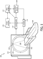
- FIGURE 1 illustrates an imaging system 100 such as a computed tomography (CT) scanner.
- CT computed tomography
- the imaging system 100 includes a stationary gantry 102 and a rotating gantry 104, which is rotatably supported by the stationary gantry 102.
- the rotating gantry 104 is configured to rotate around an examination region 106 about a longitudinal or z-axis for performing axial or helical acquisitions.
- the rotating gantry 104 is also configured to remain at a stationary location, for example, for performing one or more surviews.
- a support 108 such as a couch, supports a subject or object in the examination region 106 and can be used to position the subject or object with respect to x, y, and/or z axes before, during and/or after scanning.
- a radiation source 110 such as an x-ray tube, is supported by the rotating gantry 104 and rotates with the rotating gantry 104, when the rotating gantry 104 is rotated, about the examination region 106.
- the radiation source 110 emits radiation that traverses the examination region 106.
- a radiation sensitive detector array 112 is located opposite the radiation source 110, across the examination region 106.
- the detector array 112 includes a one or two dimensional array of radiation sensitive detector elements that detect radiation traversing the examination region 106 and generate projection data indicative thereof.
- a reconstructor 114 reconstructs the projection data and generates two dimensional (2D) and/or three dimensional (3D) volumetric image data indicative of the examination region 106 and a portion of an object or subject therein.
- the resulting volumetric image data can be processed by an image processor or the like to generate one or more images.
- a general purpose computing system serves as an operator console 116, and includes an output device such as a display and an input device such as a keyboard, mouse, and/or the like.
- Software resident on the console 116 allows the operator to control the operation of the system 100, for example, allowing the operator to initiate scanning, etc.
- An acquisition planner 118 facilitates generating acquisition plans that are conveyed to the console 116 to be implemented by the scanner 100. As described in greater detail below, in one instance, the acquisition planner 118 generates a plan for a follow up (or subsequent) acquisition of tissue of interest of a patient based on a baseline surview(s) (e.g., generated by the scanner 100) used to plan a baseline acquisition of the tissue of interest of the patient and a subsequent surview(s) (e.g., generated by the scanner 100) for planning the follow up acquisition. This allows for automatically replicating the scan geometry of the baseline acquisition of a patient with respect to the tissue of interest position and orientation. Note that the baseline and follow-up acquisitions can be performed with different CT scanners.
- An image processor 120 facilitates processing reconstructed image data, such as data from the reconstructor 114.
- the image processor 120 matches thin slices (e.g. 0.5 mm thick) from reconstructed image data from the follow up acquisition (e.g., produced by the reconstructor 114) that correspond to slices in a baseline image set, which may include the entire reconstructed image data for the baseline acquisition (e.g., produced by the reconstructor 114) with thin slices that may or may not have the same slice thickness as the follow up acquisition thin slices or a subset thereof that have been processed and include thicker slices (e.g., produced by the image processor 120).
- This matching allows a better comparison of the tissue of interest in the two acquisitions relative to a configuration in which the image processor 120 is not employed.
- the acquisition planner 118 and/or the image processor 120 can be part of a computing system such as a computer. In this instance, the acquisition planner 118 and/or the image processor 120 can be located local to or remote from the scanner 100. In another instance, the acquisition planner 118 and/or the image processor 120 is part of the console 116. In either instance, the acquisition planner 118 and/or the image processor 120 can be implemented via one or more processors that execute one or more computer readable instructions embedded on computer readable medium such as physical memory. Additionally or alternatively, the one or more processors execute one or more computer readable instructions carried by a signal or carrier wave.
- a data repository 122 is configured to store electronically formatted data, including, but not limited to, surviews (e.g., generated by the scanner 100), reconstructed image data (e.g., generated by the scanner 100), processed image data (e.g., generated by the image processor 120), and/or other information. This data can be used by the acquisition planner 118 to facilitate generating acquisition plans and/or the image processor 120 to facilitate processing reconstructed data.
- the data repository 122 can include one or more storage components such as a PACS, a radiology information system (RIS), a hospital information system (HIS), an electronic medical record (EMR), a database, a server, and/or other repository.
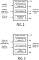
- FIGURE 2 schematically illustrates an example of the acquisition planner 118.
- the acquisition planner 118 is discussed in connection with planning a follow up acquisition of the same tissue of interest of the same patient.
- the acquisition planner 118 utilizes a baseline surview(s) (e.g., generated by the scanner 100 and stored in the data repository 122), including the ROI box(s) and z-axis extent, and a follow up surview (e.g., generated by the scanner 100). It is to be understood that the acquisition planner 118 can also be utilized to plan the baseline acquisition based on the baseline surview and that this will not be discussed below.
- the illustrated acquisition planner 118 includes a two dimensional (2D) registration component 202, which registers the baseline surview(s) and the follow up surview(s). In one instance, this includes rigidly or elastically registering all or a subset of the structure represented in both to the surviews. Any known or other 2D registration algorithm can be employed.
- An example of a suitable registration includes an image pixel intensity based registration.
- a global or locally restricted similarity measure between both images can be maximized by variation of the geometric parameters (e.g., changing position and orientation of one image in rigid registration).
- the illustrated acquisition planner 118 further includes a region of interest (ROI) transferor 204 that transfers ROIs of the baseline surview(s) to the follow up surview(s) that has been registered with the baseline surview(s).
- ROI region of interest
- the illustrated acquisition planner 118 further includes a scan extent transferor 206 that transfers the scan extent (zmin and zmax) of the baseline surview(s) to the subsequent surview(s) that has been registered with the baseline surview(s).
- FIGURE 3 schematically illustrates an example of the image processor 120.
- the image processor 120 is discussed in connection with matching images of the follow up reconstruction with corresponding images of the baseline image set. It is to be understood that the image processor 120 can also be utilized to process the baseline acquisition.
- the image processor 120 includes a three dimensional (3D) elastic or rigid registration component 302, which registers the baseline images and the subsequent reconstructed thin slice images. Any known or other 3D registration algorithm can be employed.
- An example of a suitable registration includes an image pixel intensity based registration.
- a global or locally restricted similarity measure between both images can be maximized by variation of the geometric parameters (e.g., changing position and orientation of one image in rigid registration).
- the registration includes registering the baseline reconstructed images and/or the subset of processed images derived from the baseline reconstructed images with the reconstructed images of the follow up acquisition. This registration allows for refining the position of the follow up ROI(s), thereby optimizing alignment of the ROI(s) in the reconstructed images of the two acquisitions.
- a data reformattor 306 reformats the thin slice reconstructed images of the follow up acquisition based on the registration transformation. This may include creating a set of images from the set of registered thin slice image using image processing approaches such as multi-planar reconstruction (MPR) and/or other image processing approaches.
- the resulting image dataset includes a three dimensional image dataset that substantially matches the three dimensional subset of reconstructed images derived from the baseline acquisition.
- the resulting image dataset can be visually presented via a display monitor, stored, conveyed to one or more or devices, further processed, filmed, etc.
- the estimation from the registration of the baseline and follow up surviews is used to guide this 3D registration.
- the 3D search space is already strongly limited by it, especially in the in-plane orientations of the surview. This way, the capture range problem of the 3D registration is already limited. This increases robustness and speeds up computation. In case a dual projection surview is available (two orthogonal projections of the patient), these restrictions can be made even stronger.
- the image processor 120 also includes a volume of interest (VOI) transferor 304 that transfers VOIs from the baseline image set to the follow up image set.
- VOI volume of interest
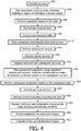
- FIGURE 4 schematically illustrates an example method for performing CT scans.
- At 402 at least one surview is performed for a patient to be scanned. Where there are multiple surviews, the surviews can be performed with the radiation source 110 located at different angular positions.
- an acquisition plan is created, based on the surview(s), for scanning tissue of interest of the patient. This includes defining one or more ROIs for tissue of interest and a z-axis scan extent on the surview.
- an acquisition is performed based on the plan.
- the acquired data is reconstructed, creating a plurality of thin slices.
- the reconstructed data is processed. In one instance, this includes creating a subset of images for the tissue of interest, where the images have a greater slice thickness relative to the reconstructed thins slices and includes at least one user identified volume of interest (VOI).
- VOI volume of interest
- the surview with the ROIs and the z-axis extent and the subset of images are stored.
- the original reconstructed slices are also stored.
- At 414 at least one follow up surview for planning a follow-up acquisition of the tissue is performed.
- the one or more stored surviews including the one or more ROIs and the z-axis extent, are retrieved. This data can be pre-fetched or obtained when needed.
- the one or more follow up surviews are registered with the one or more retrieved surviews, including transferring the ROIs and z-axis extent of the retrieved surviews to the follow up surviews.
- the registration is automatically performed without any user interaction. In another instance, the registration is performed under user interaction. The resulting registration can be accepted, modified or rejected.
- a follow up acquisition plan is created based on the registered subsequent surview, including the registered ROIs and z-axis extent.
- the plan is automatically created without any user interaction.
- the plan is created under user interaction.
- the resulting plan can be accepted, modified or rejected.
- a follow up acquisition is performed based on the follow up acquisition plan.
- the acquired data is reconstructed, creating a plurality of thin slices.
- the stored subset of reconstructed images is retrieved. Additionally or alternatively, the stored reconstructed data is retrieved.
- the reconstructed thin slice images of the reconstructed data are registered with the retrieved subset of reconstructed images, including transferring the at least one VOI.
- the images in both sets cover the same tissue of interest, slice-by-slice.
- the registered reconstructed images are processed. In one instance, this includes creating a subset of images for the tissue of interest.
- the tissue of interest in the follow up processed images is compared with the tissue of interest in the baseline processed images. This may include visually and/or quantitatively comparing the tissue of interest of the two data sets.
- the above may be implemented via one or more processors executing one or more computer readable instructions encoded or embodied on computer readable storage medium such as physical memory which causes the one or more processors to carry out the various acts and/or other functions and/or acts. Additionally or alternatively, the one or more processors can execute instructions carried by transitory medium such as a signal or carrier wave.
- the above can facilitate driving the acquisition and reconstruction of a follow-up exam such that the follow-up and baseline 3D images are substantially identical on a slice-by-slice basis (e.g. slice #38 of the baseline and follow-up datasets contain the same anatomical structures, with as less through-plane and in-plane translation / angulation as possible).
- a MPR in the desired orientation can be computed directly, therefore reducing artifacts due to partial volume, relative to a configuration in which baseline and follow-up images with relatively thick slices are registered together, and the thick-slice follow-up image is reformatted to match the baseline image, which results in stronger partial-volume effect.
- CT acquisition plans can additionally or alternatively be generated based on data from other imaging modalities.
- plans for other imaging modalities can be generated based on a CT surview and/or data generated based on other imaging modalities.
Description
- The following generally relates to generating a follow up image acquisition plan and/or post processing of the data generated by the follow up image acquisition and is described with particular application to computed tomography (CT); however, the following is also amenable to other imaging modalities.
- A CT scanner includes an x-ray tube supported by a rotating gantry, which is rotatably affixed to a stationary gantry. The x-ray tube emits radiation that traverses an examination region and a portion of a patient therein (which attenuates the radiation as a function of the radiodensity of the patient). A subject support supports the patient and is configured to position the patient in the examination region for scanning. A detector array disposed across the examination region, opposite the x-ray tube, detects radiation traversing the examination region and produces projection data indicative of the detected radiation. The projection data can be reconstructed to generate three dimensional (3D) volumetric image data indicative of the portion of the patient.
- For a CT acquisition (e.g. axial or helical), generally, a surview is first performed. The surview is acquired with the rotating gantry at a static position (not rotating) and with the subject support moving in the z direction through the examination region. The resulting data is a two dimensional (2D) projection image of the scanned portion of the patient. The 2D projection image is used to generate a plan for the CT acquisition, including identifying tissue of interest to be scanned during the CT acquisition and the z-axis extent of the patient (i.e., zmin and zmax) of the CT acquisition based on the tissue of interest. The extent is typically determined by the technician at the console on the 2D projection image by positioning and overlaying a region of interest (ROI) box that covers the tissue of interest.
- Once planned, the CT acquisition can be performed. The acquired data is reconstructed, producing the 3D volumetric image data. However, typically, only a subset of the reconstructed data, for example, the portion corresponding particularly to the tissue of interest is further processed, for instance, optimized for visual inspection. This subset often includes slices with a thickness that is larger than the slices in the original reconstructed 3D volumetric image data. Furthermore, the subset may include images in multiple orientations (i.e., sagittal, transversal, and/or coronal). The subset and the surview is formatted in accordance with the Digital Imaging and Communications in Medicine (DICOM) standard and stored in a Picture Archiving and Communications System (PACS). The original reconstructed data may not be stored, e.g., due to its size.
- CT acquisitions of the same tissue at different moments in time have been compared to obtain information about the tissue. For example, such acquisitions have been utilized to visually observe and/or quantify physical changes (e.g., growth or shrinkage) in the geometry of a tumor or other tissue over time. However, in order for the obtained information to be diagnostically useful, the acquisition settings should be similar. By way of example, if, for instance, the tumor diameter is measured in a baseline image in a given CT slice, the follow-up image should have geometry such that there is a corresponding slice with respect to the tumor position. Otherwise a difference in size of the tumor in the two data sets may be incorrectly estimated.
- Typically, there is a standard operating procedure for a given examination type in a radiology department that determines where to place the ROI boxes. Unfortunately, the variability to be observed in real clinical data is high and does not allow an easy accurate comparison of baseline and follow-up images. Furthermore, it is extremely tedious and time consuming to manually position the ROI boxes so as to reproduce a baseline examination with sufficient accuracy. Therefore, there is an unresolved need for approaches for planning a follow up CT acquisition of tissue of interest where the tissue of interest in the resulting images is well suited for comparison with the tissue of interest in the baseline images.
- Document
US2009/147909 A1 may be considered to disclose a system, comprising: an acquisition planner configured to generate an acquisition plan for a follow up three dimensional image acquisition based on a first two dimensional surview projection image and a second two dimensional surview projection image, wherein the first two dimensional surview projection image was used to plan a previously performed three dimensional image acquisition, and the second two dimensional surview projection image was acquired for planning the follow up three dimensional image acquisition. - Aspects of the present patent address the above-referenced matters and others.
- According to one aspect, a method includes planning a follow up three dimensional image acquisition of tissue of interest of a patient based on first and second two dimensional surview projection images, wherein the first two dimensional surview projection image was used to plan a previously performed baseline three dimensional image acquisition of the tissue of interest of the patient, wherein the first two dimensional surview projection image includes information corresponding to at least one region of interest identified in the first two dimensional surview projection image for the previously performed baseline three dimensional image acquisition, wherein the first two dimensional surview projection image includes information corresponding to a z-axis scanning extent identified in the first two dimensional surview projection image for the previously performed baseline three dimensional baseline image acquisition, and wherein the second two dimensional surview projection image was acquired for planning the follow up three dimensional image acquisition.
- In another aspect, a system includes an acquisition planner configured to generate an acquisition plan for a follow up three dimensional image acquisition based on a first and second two dimensional surview projection images, wherein the first two dimensional surview projection image was used to plan a previously performed three dimensional image acquisition, and the second two dimensional surview projection image was acquired for planning the follow up three dimensional image acquisition.
- In another aspect, computer readable medium embedded with computer executable instructions, which, when executed by a processor, causes the processor to: register a follow up
surview 2D projection image performed for planning a subsequent three dimensional image acquisition with abaseline surview 2D projection image of a previously performed baseline a three dimensional image acquisition, transfer information corresponding to a region of interest identified in thebaseline surview 2D projection image to the follow upsurview 2D projection image, transfer information corresponding to a z-axis extent of the previously performed baseline a three dimensional image acquisition identified in thebaseline surview 2D projection image to the follow upsurview 2D projection image, and generating an acquisition plan for the subsequent three dimensional image acquisition based on the registered follow upsurview 2D projection image with the transferred region of interest and z-axis extent, wherein the plan is used to perform the subsequent three dimensional image acquisition. - Still further aspects of the present disclosure will be appreciated to those of ordinary skill in the art upon reading and understanding the following detailed description.
- The disclosure may take form in various components and arrangements of components, and in various steps and arrangements of steps. The drawings are only for purposes of illustrating the preferred embodiments and are not to be construed as limiting the invention.
-
FIGURE 1 schematically illustrates an example imaging system in connection with an acquisition planner and an image processor. -
FIGURE 2 schematically illustrates an example of the acquisition planner. -
FIGURE 3 schematically illustrates an example of the image processor. -
FIGURE 4 illustrates an example method for performing CT scans. - The following generally relates to replicating scan geometry of tissue of interest of a patient in a baseline image acquisition (e.g., position and orientation) for a follow up image acquisition of the same tissue of interest of the same patient. This allows for a better comparison of follow up images with baseline images as corresponding slices from both acquisitions cover the same anatomical extent. As used herein, "baseline" and "follow up" refer to acquisitions performed at different moments in time, wherein the "baseline" acquisition is performed before the "follow up" acquisition (or the "follow up" acquisition is performed subsequent to the "baseline" acquisition). However, the "baseline" acquisition is not necessarily the first acquisition, and the "follow up" acquisition is not necessarily the first acquisition performed after the "baseline" acquisition.
-
FIGURE 1 illustrates animaging system 100 such as a computed tomography (CT) scanner. - The
imaging system 100 includes astationary gantry 102 and a rotatinggantry 104, which is rotatably supported by thestationary gantry 102. The rotatinggantry 104 is configured to rotate around anexamination region 106 about a longitudinal or z-axis for performing axial or helical acquisitions. The rotatinggantry 104 is also configured to remain at a stationary location, for example, for performing one or more surviews. Asupport 108, such as a couch, supports a subject or object in theexamination region 106 and can be used to position the subject or object with respect to x, y, and/or z axes before, during and/or after scanning. - A
radiation source 110, such as an x-ray tube, is supported by the rotatinggantry 104 and rotates with the rotatinggantry 104, when the rotatinggantry 104 is rotated, about theexamination region 106. Theradiation source 110 emits radiation that traverses theexamination region 106. A radiationsensitive detector array 112 is located opposite theradiation source 110, across theexamination region 106. Thedetector array 112 includes a one or two dimensional array of radiation sensitive detector elements that detect radiation traversing theexamination region 106 and generate projection data indicative thereof. - A
reconstructor 114 reconstructs the projection data and generates two dimensional (2D) and/or three dimensional (3D) volumetric image data indicative of theexamination region 106 and a portion of an object or subject therein. The resulting volumetric image data can be processed by an image processor or the like to generate one or more images. A general purpose computing system serves as anoperator console 116, and includes an output device such as a display and an input device such as a keyboard, mouse, and/or the like. Software resident on theconsole 116 allows the operator to control the operation of thesystem 100, for example, allowing the operator to initiate scanning, etc. - An
acquisition planner 118 facilitates generating acquisition plans that are conveyed to theconsole 116 to be implemented by thescanner 100. As described in greater detail below, in one instance, theacquisition planner 118 generates a plan for a follow up (or subsequent) acquisition of tissue of interest of a patient based on a baseline surview(s) (e.g., generated by the scanner 100) used to plan a baseline acquisition of the tissue of interest of the patient and a subsequent surview(s) (e.g., generated by the scanner 100) for planning the follow up acquisition. This allows for automatically replicating the scan geometry of the baseline acquisition of a patient with respect to the tissue of interest position and orientation. Note that the baseline and follow-up acquisitions can be performed with different CT scanners. - An
image processor 120 facilitates processing reconstructed image data, such as data from thereconstructor 114. As described in greater detail below, in one instance, theimage processor 120 matches thin slices (e.g. 0.5 mm thick) from reconstructed image data from the follow up acquisition (e.g., produced by the reconstructor 114) that correspond to slices in a baseline image set, which may include the entire reconstructed image data for the baseline acquisition (e.g., produced by the reconstructor 114) with thin slices that may or may not have the same slice thickness as the follow up acquisition thin slices or a subset thereof that have been processed and include thicker slices (e.g., produced by the image processor 120). This matching allows a better comparison of the tissue of interest in the two acquisitions relative to a configuration in which theimage processor 120 is not employed. - The
acquisition planner 118 and/or theimage processor 120 can be part of a computing system such as a computer. In this instance, theacquisition planner 118 and/or theimage processor 120 can be located local to or remote from thescanner 100. In another instance, theacquisition planner 118 and/or theimage processor 120 is part of theconsole 116. In either instance, theacquisition planner 118 and/or theimage processor 120 can be implemented via one or more processors that execute one or more computer readable instructions embedded on computer readable medium such as physical memory. Additionally or alternatively, the one or more processors execute one or more computer readable instructions carried by a signal or carrier wave. - A
data repository 122 is configured to store electronically formatted data, including, but not limited to, surviews (e.g., generated by the scanner 100), reconstructed image data (e.g., generated by the scanner 100), processed image data (e.g., generated by the image processor 120), and/or other information. This data can be used by theacquisition planner 118 to facilitate generating acquisition plans and/or theimage processor 120 to facilitate processing reconstructed data. Thedata repository 122 can include one or more storage components such as a PACS, a radiology information system (RIS), a hospital information system (HIS), an electronic medical record (EMR), a database, a server, and/or other repository. -
FIGURE 2 schematically illustrates an example of theacquisition planner 118. - In this example, the
acquisition planner 118 is discussed in connection with planning a follow up acquisition of the same tissue of interest of the same patient. In this context, theacquisition planner 118 utilizes a baseline surview(s) (e.g., generated by thescanner 100 and stored in the data repository 122), including the ROI box(s) and z-axis extent, and a follow up surview (e.g., generated by the scanner 100). It is to be understood that theacquisition planner 118 can also be utilized to plan the baseline acquisition based on the baseline surview and that this will not be discussed below. - The illustrated
acquisition planner 118 includes a two dimensional (2D)registration component 202, which registers the baseline surview(s) and the follow up surview(s). In one instance, this includes rigidly or elastically registering all or a subset of the structure represented in both to the surviews. Any known or other 2D registration algorithm can be employed. An example of a suitable registration includes an image pixel intensity based registration. A global or locally restricted similarity measure between both images can be maximized by variation of the geometric parameters (e.g., changing position and orientation of one image in rigid registration). - The illustrated
acquisition planner 118 further includes a region of interest (ROI) transferor 204 that transfers ROIs of the baseline surview(s) to the follow up surview(s) that has been registered with the baseline surview(s). The illustratedacquisition planner 118 further includes a scan extent transferor 206 that transfers the scan extent (zmin and zmax) of the baseline surview(s) to the subsequent surview(s) that has been registered with the baseline surview(s). -
FIGURE 3 schematically illustrates an example of theimage processor 120. - In this example, the
image processor 120 is discussed in connection with matching images of the follow up reconstruction with corresponding images of the baseline image set. It is to be understood that theimage processor 120 can also be utilized to process the baseline acquisition. - The
image processor 120 includes a three dimensional (3D) elastic orrigid registration component 302, which registers the baseline images and the subsequent reconstructed thin slice images. Any known or other 3D registration algorithm can be employed. An example of a suitable registration includes an image pixel intensity based registration. A global or locally restricted similarity measure between both images can be maximized by variation of the geometric parameters (e.g., changing position and orientation of one image in rigid registration). - In one instance, the registration includes registering the baseline reconstructed images and/or the subset of processed images derived from the baseline reconstructed images with the reconstructed images of the follow up acquisition. This registration allows for refining the position of the follow up ROI(s), thereby optimizing alignment of the ROI(s) in the reconstructed images of the two acquisitions.
- A
data reformattor 306 reformats the thin slice reconstructed images of the follow up acquisition based on the registration transformation. This may include creating a set of images from the set of registered thin slice image using image processing approaches such as multi-planar reconstruction (MPR) and/or other image processing approaches. In one instance, the resulting image dataset includes a three dimensional image dataset that substantially matches the three dimensional subset of reconstructed images derived from the baseline acquisition. The resulting image dataset can be visually presented via a display monitor, stored, conveyed to one or more or devices, further processed, filmed, etc. - Generally, the estimation from the registration of the baseline and follow up surviews is used to guide this 3D registration. The 3D search space is already strongly limited by it, especially in the in-plane orientations of the surview. This way, the capture range problem of the 3D registration is already limited. This increases robustness and speeds up computation. In case a dual projection surview is available (two orthogonal projections of the patient), these restrictions can be made even stronger.
- The
image processor 120 also includes a volume of interest (VOI) transferor 304 that transfers VOIs from the baseline image set to the follow up image set. -
FIGURE 4 schematically illustrates an example method for performing CT scans. - It is to be appreciated that the ordering of the below acts is for explanatory purposes and not limiting. As such, other orderings are also contemplated herein. In addition, one or more of the acts may be omitted and/or one or more other acts may be included.
- At 402, at least one surview is performed for a patient to be scanned. Where there are multiple surviews, the surviews can be performed with the
radiation source 110 located at different angular positions. - At 404, an acquisition plan is created, based on the surview(s), for scanning tissue of interest of the patient. This includes defining one or more ROIs for tissue of interest and a z-axis scan extent on the surview.
- At 406, an acquisition is performed based on the plan.
- At 408, the acquired data is reconstructed, creating a plurality of thin slices.
- At 410, the reconstructed data is processed. In one instance, this includes creating a subset of images for the tissue of interest, where the images have a greater slice thickness relative to the reconstructed thins slices and includes at least one user identified volume of interest (VOI).
- At 412, the surview with the ROIs and the z-axis extent and the subset of images are stored. Optionally, the original reconstructed slices are also stored.
- At 414, at least one follow up surview for planning a follow-up acquisition of the tissue is performed.
- At 416, the one or more stored surviews, including the one or more ROIs and the z-axis extent, are retrieved. This data can be pre-fetched or obtained when needed.
- At 418, the one or more follow up surviews are registered with the one or more retrieved surviews, including transferring the ROIs and z-axis extent of the retrieved surviews to the follow up surviews. In one instance, the registration is automatically performed without any user interaction. In another instance, the registration is performed under user interaction. The resulting registration can be accepted, modified or rejected.
- At 420, a follow up acquisition plan is created based on the registered subsequent surview, including the registered ROIs and z-axis extent. In one instance, the plan is automatically created without any user interaction. In another instance, the plan is created under user interaction. The resulting plan can be accepted, modified or rejected.
- At 422, a follow up acquisition is performed based on the follow up acquisition plan.
- At 424, the acquired data is reconstructed, creating a plurality of thin slices.
- At 426, the stored subset of reconstructed images is retrieved. Additionally or alternatively, the stored reconstructed data is retrieved.
- At 428, the reconstructed thin slice images of the reconstructed data are registered with the retrieved subset of reconstructed images, including transferring the at least one VOI. The images in both sets cover the same tissue of interest, slice-by-slice.
- At 430, the registered reconstructed images are processed. In one instance, this includes creating a subset of images for the tissue of interest.
- At 432, the tissue of interest in the follow up processed images is compared with the tissue of interest in the baseline processed images. This may include visually and/or quantitatively comparing the tissue of interest of the two data sets.
- Where another follow up acquisition is to be planned, one or more of
acts 414 to 432 are repeated, using the initial surview, the first follow up surview, both of these surviews, and/or another surview. - The above may be implemented via one or more processors executing one or more computer readable instructions encoded or embodied on computer readable storage medium such as physical memory which causes the one or more processors to carry out the various acts and/or other functions and/or acts. Additionally or alternatively, the one or more processors can execute instructions carried by transitory medium such as a signal or carrier wave.
- It is to be appreciated that the above can facilitate driving the acquisition and reconstruction of a follow-up exam such that the follow-up and
baseline 3D images are substantially identical on a slice-by-slice basis (e.g. slice #38 of the baseline and follow-up datasets contain the same anatomical structures, with as less through-plane and in-plane translation / angulation as possible). By computing a transformation based on a thin-slice reconstruction of the follow-up exam (before the image with thicker slices is reconstructed), a MPR in the desired orientation can be computed directly, therefore reducing artifacts due to partial volume, relative to a configuration in which baseline and follow-up images with relatively thick slices are registered together, and the thick-slice follow-up image is reformatted to match the baseline image, which results in stronger partial-volume effect. - The above is discussed in terms of planning a CT acquisition based on CT surviews. However, it is to be appreciated the CT acquisition plans can additionally or alternatively be generated based on data from other imaging modalities. In addition, plans for other imaging modalities can be generated based on a CT surview and/or data generated based on other imaging modalities.
- The invention is defined in the claims and has been described herein with reference to the various embodiments. Modifications and alterations may occur to others upon reading the description herein.
Claims (13)
- A method, comprising:
registering first and second two dimensional surview projection images, planning a follow up three dimensional image acquisition of tissue of interest of a patient based on the registered first two dimensional surview projection image and second two dimensional surview projection image, wherein the planning of the follow up three dimensional image acquisition is based on the registered first and second two dimensional surview projection images,
wherein the first two dimensional surview projection image was used to plan a previously performed baseline three dimensional image acquisition of the tissue of interest of the patient, wherein the first two dimensional surview projection image includes information corresponding to at least one region of interest identified in the first two dimensional surview projection image for the previously performed baseline three dimensional image acquisition, wherein the first two dimensional surview projection image includes information corresponding to a z-axis scanning extent identified in the first two dimensional surview projection image for the previously performed baseline three dimensional baseline image acquisition, and wherein the method comprises:
transferring the information corresponding to the z-axis scanning extent from the registered first two dimensional surview projection image to the registered second two dimensional surview projection image
wherein the second two dimensional surview projection image was acquired for planning the follow up three dimensional image acquisition. - The method of claim 1, the registering, comprising:
using an elastic or a rigid image registration algorithm to register first and second two dimensional surview projection images. - The method of any of claims 1 to 2, the registering, comprising:
transferring the information corresponding to the at least one region of interest from the first two dimensional surview projection image to the second two dimensional surview projection image. - The method of any of claims 1 to 3, wherein the registering is performed automatically without user interaction.
- The method of any of claims 1 to 4, further comprising:
performing the follow up three dimensional image acquisition based on the registered second two dimensional surview projection image with the transferred information. - The method of any of claims 1 to 5, further comprising:reconstructing data acquired during the follow up three dimensional image acquisition, generating a plurality of thin slice images; andregistering the thin slice images with a subset of images corresponding to the previously performed three dimensional baseline image acquisition.
- The method of any of claims 5 to 6, wherein the subset of images have thicker slice thicknesses relative to the thin slice images generated from the previously performed three dimensional baseline image acquisition.
- The method of any of claims 4 to 7, the registering, comprising:
transferring information corresponding to a volume of interest identified in the subset of images from the subset to the registered plurality of thin slice images. - The method of claim 8, further comprising:
reformatting the plurality of thin slice images, producing a three dimensional image dataset that substantially matches the subset of images corresponding to the previously performed three dimensional baseline image acquisition. - A system (100), comprising:a 2D registration component (204) configured to register first and second two dimensional surview projection images,an acquisition planner (118) configured to generate an acquisition plan for a follow up three dimensional image acquisition based on the first two dimensional surview projection image and second two dimensional surview projection images, wherein the first two dimensional surview projection image was used to plan a previously performed three dimensional image acquisition,a scan extent transferor (206) configured to transfers information corresponding to a z-axis scanning extent identified in the registered first two dimensional surview projection image for the previously performed three dimensional image acquisition to the registered second two dimensional surview projection image,wherein the second two dimensional surview projection image was acquired for planning the follow up three dimensional image acquisition.
- The system (100) of claim 10, the acquisition planner (118), further comprising:
a region of interest transferor (204) that transfers information corresponding to at least one region of interest identified in the first two dimensional surview projection image to the second two dimensional surview projection image. - The system (100) of any of claims 10 to 11, further comprising:
an image processor (120) that matches thin slice images of the follow up three dimensional image acquisition with a subset of thicker slice images derived from the thin slice images of the previously performed three dimensional image acquisition. - The system (100) of claim 12, the image processor, (120) comprising:
a 3D registration component (302) configured to register the thin slice images and the thicker slice images.
Applications Claiming Priority (2)
| Application Number | Priority Date | Filing Date | Title |
|---|---|---|---|
| US201161504840P | 2011-07-06 | 2011-07-06 | |
| PCT/IB2012/053296 WO2013005146A1 (en) | 2011-07-06 | 2012-06-28 | Follow up image acquisition planning and/or post processing |
Publications (2)
| Publication Number | Publication Date |
|---|---|
| EP2729071A1 EP2729071A1 (en) | 2014-05-14 |
| EP2729071B1 true EP2729071B1 (en) | 2020-05-20 |
Family
ID=46640708
Family Applications (1)
| Application Number | Title | Priority Date | Filing Date |
|---|---|---|---|
| EP12745713.3A Active EP2729071B1 (en) | 2011-07-06 | 2012-06-28 | Follow up image acquisition planning and/or post processing |
Country Status (5)
| Country | Link |
|---|---|
| US (1) | US9675311B2 (en) |
| EP (1) | EP2729071B1 (en) |
| JP (1) | JP2014518125A (en) |
| CN (1) | CN103648390B (en) |
| WO (1) | WO2013005146A1 (en) |
Families Citing this family (6)
| Publication number | Priority date | Publication date | Assignee | Title |
|---|---|---|---|---|
| CN105578958B (en) * | 2013-09-27 | 2019-05-28 | 皇家飞利浦有限公司 | System and method for context-aware imaging |
| CN104978754A (en) * | 2014-04-03 | 2015-10-14 | 上海联影医疗科技有限公司 | Medical image off-line reconstruction positioning method |
| CN105030266B (en) * | 2014-04-21 | 2018-01-12 | 东芝医疗系统株式会社 | X ray computed tomographics device and scan plan set supporting device |
| US10032250B2 (en) * | 2015-01-30 | 2018-07-24 | Koninklijke Philips N.V. | Automated scan planning for follow-up magnetic resonance imaging |
| EP3683765A1 (en) * | 2019-01-18 | 2020-07-22 | Koninklijke Philips N.V. | System for determining a tissue-specific property |
| CN111728627A (en) * | 2020-06-02 | 2020-10-02 | 北京昆仑医云科技有限公司 | Diagnosis support method and diagnosis support device |
Citations (2)
| Publication number | Priority date | Publication date | Assignee | Title |
|---|---|---|---|---|
| JP2008012171A (en) * | 2006-07-07 | 2008-01-24 | Toshiba Corp | Medical imaging apparatus |
| WO2008129506A1 (en) * | 2007-04-23 | 2008-10-30 | Koninklijke Philips Electronics N.V. | Scan planning with self-learning capability |
Family Cites Families (18)
| Publication number | Priority date | Publication date | Assignee | Title |
|---|---|---|---|---|
| JPS59111191A (en) * | 1982-12-16 | 1984-06-27 | 株式会社 日立メデイコ | Medical image display |
| JP3184331B2 (en) | 1992-09-29 | 2001-07-09 | マツダ株式会社 | Route guidance device by voice of car |
| JPH10108073A (en) * | 1996-09-27 | 1998-04-24 | Fuji Photo Film Co Ltd | Method and device for processing bone part image |
| JP2003299643A (en) * | 2002-04-11 | 2003-10-21 | Hitachi Medical Corp | Tomographic equipment |
| JP3747183B2 (en) * | 2002-04-18 | 2006-02-22 | キヤノン株式会社 | Image processing apparatus and image processing method |
| JP2005012248A (en) * | 2003-06-16 | 2005-01-13 | Fuji Photo Film Co Ltd | Method and apparatus of assisting image reading |
| JP3989896B2 (en) * | 2003-12-25 | 2007-10-10 | ザイオソフト株式会社 | Medical image processing apparatus, region of interest extraction method, and program |
| US20080085041A1 (en) | 2004-11-29 | 2008-04-10 | Koninklijke Philips Electronics, N.V. | Method Of Geometrical Distortion Correction In 3D Images |
| US7831073B2 (en) * | 2005-06-29 | 2010-11-09 | Accuray Incorporated | Precision registration of X-ray images to cone-beam CT scan for image-guided radiation treatment |
| US7207715B2 (en) * | 2005-07-29 | 2007-04-24 | Upmc | Method to implement full six-degree target shift corrections in radiotherapy |
| US7747050B2 (en) | 2005-11-23 | 2010-06-29 | General Electric Company | System and method for linking current and previous images based on anatomy |
| CA2640802A1 (en) * | 2005-12-20 | 2007-09-13 | University Of Maryland, Baltimore | Method and apparatus for accelerated elastic registration of multiple scans of internal properties of a body |
| DE102006017932A1 (en) * | 2006-04-18 | 2007-10-25 | Siemens Ag | Method for controlling the recording and / or evaluation operation of image data in medical examinations |
| US8045771B2 (en) | 2006-11-22 | 2011-10-25 | General Electric Company | System and method for automated patient anatomy localization |
| US8175352B2 (en) | 2007-09-21 | 2012-05-08 | Siemens Aktiengesellschaft | System and method for automated magnetic resonance scan prescription for optic nerves |
| JP2009142300A (en) * | 2007-12-11 | 2009-07-02 | Toshiba Corp | X-ray ct system and method for creating scanning plan |
| BRPI1007717A2 (en) * | 2009-04-13 | 2017-01-31 | Koninl Philips Electronics Nv | image processing system and method for determining plausible reference information from image data |
| CN102711617B (en) * | 2009-11-16 | 2014-12-24 | 皇家飞利浦电子股份有限公司 | Scan plan field of view adjustor, determiner, and/or quality assessor |
-
2012
- 2012-06-28 JP JP2014518035A patent/JP2014518125A/en active Pending
- 2012-06-28 EP EP12745713.3A patent/EP2729071B1/en active Active
- 2012-06-28 CN CN201280033271.6A patent/CN103648390B/en active Active
- 2012-06-28 US US14/126,276 patent/US9675311B2/en active Active
- 2012-06-28 WO PCT/IB2012/053296 patent/WO2013005146A1/en active Application Filing
Patent Citations (2)
| Publication number | Priority date | Publication date | Assignee | Title |
|---|---|---|---|---|
| JP2008012171A (en) * | 2006-07-07 | 2008-01-24 | Toshiba Corp | Medical imaging apparatus |
| WO2008129506A1 (en) * | 2007-04-23 | 2008-10-30 | Koninklijke Philips Electronics N.V. | Scan planning with self-learning capability |
Also Published As
| Publication number | Publication date |
|---|---|
| EP2729071A1 (en) | 2014-05-14 |
| US20140198964A1 (en) | 2014-07-17 |
| US9675311B2 (en) | 2017-06-13 |
| JP2014518125A (en) | 2014-07-28 |
| CN103648390B (en) | 2016-10-19 |
| WO2013005146A1 (en) | 2013-01-10 |
| CN103648390A (en) | 2014-03-19 |
Similar Documents
| Publication | Publication Date | Title |
|---|---|---|
| JP6145178B2 (en) | Medical image alignment | |
| US9251585B2 (en) | Coregistration and analysis of multi-modal images obtained in different geometries | |
| US8625869B2 (en) | Visualization of medical image data with localized enhancement | |
| US7574030B2 (en) | Automated digitized film slicing and registration tool | |
| EP2729071B1 (en) | Follow up image acquisition planning and/or post processing | |
| US9082231B2 (en) | Symmetry-based visualization for enhancing anomaly detection | |
| US20090022386A1 (en) | Methods and systems for computer aided targeting | |
| US20220249038A1 (en) | Determining Rotational Orientation Of A Deep Brain Stimulation Electrode In A Three-Dimensional Image | |
| US20050135707A1 (en) | Method and apparatus for registration of lung image data | |
| EP2939217B1 (en) | Computer-aided identification of a tissue of interest | |
| US20160287201A1 (en) | One or more two dimensional (2d) planning projection images based on three dimensional (3d) pre-scan image data | |
| EP2245592B1 (en) | Image registration alignment metric | |
| US7620229B2 (en) | Method and apparatus for aiding image interpretation and computer-readable recording medium storing program therefor | |
| US10657621B2 (en) | Moving structure motion compensation in imaging | |
| US20160078615A1 (en) | Visualization of Anatomical Labels | |
| US20100303314A1 (en) | Systems and methods for detecting and visualizing correspondence corridors on two-dimensional and volumetric medical images | |
| Azar et al. | Standardized platform for coregistration of nonconcurrent diffuse optical and magnetic resonance breast images obtained in different geometries | |
| US11495346B2 (en) | External device-enabled imaging support | |
| CN111919264A (en) | System and method for synchronizing an imaging system and an edge calculation system | |
| Shamul et al. | Change detection in sparse repeat CT scans with non-rigid deformations | |
| US20240020860A1 (en) | Method and apparatus of fusion of multimodal images to fluoroscopic images | |
| US20240013381A1 (en) | Systems and methods for co-registering imagery of different modalities | |
| Wang et al. | CT dose minimization using personalized protocol optimization and aggressive bowtie | |
| CN114159085A (en) | PET image attenuation correction method and device, electronic equipment and storage medium |
Legal Events
| Date | Code | Title | Description |
|---|---|---|---|
| PUAI | Public reference made under article 153(3) epc to a published international application that has entered the european phase |
Free format text: ORIGINAL CODE: 0009012 |
|
| 17P | Request for examination filed |
Effective date: 20140206 |
|
| AK | Designated contracting states |
Kind code of ref document: A1 Designated state(s): AL AT BE BG CH CY CZ DE DK EE ES FI FR GB GR HR HU IE IS IT LI LT LU LV MC MK MT NL NO PL PT RO RS SE SI SK SM TR |
|
| DAX | Request for extension of the european patent (deleted) | ||
| STAA | Information on the status of an ep patent application or granted ep patent |
Free format text: STATUS: EXAMINATION IS IN PROGRESS |
|
| 17Q | First examination report despatched |
Effective date: 20171207 |
|
| GRAJ | Information related to disapproval of communication of intention to grant by the applicant or resumption of examination proceedings by the epo deleted |
Free format text: ORIGINAL CODE: EPIDOSDIGR1 |
|
| STAA | Information on the status of an ep patent application or granted ep patent |
Free format text: STATUS: GRANT OF PATENT IS INTENDED |
|
| GRAP | Despatch of communication of intention to grant a patent |
Free format text: ORIGINAL CODE: EPIDOSNIGR1 |
|
| INTG | Intention to grant announced |
Effective date: 20191217 |
|
| RAP1 | Party data changed (applicant data changed or rights of an application transferred) |
Owner name: PHILIPS INTELLECTUAL PROPERTY & STANDARDS GMBH Owner name: KONINKLIJKE PHILIPS N.V. |
|
| GRAS | Grant fee paid |
Free format text: ORIGINAL CODE: EPIDOSNIGR3 |
|
| GRAA | (expected) grant |
Free format text: ORIGINAL CODE: 0009210 |
|
| STAA | Information on the status of an ep patent application or granted ep patent |
Free format text: STATUS: THE PATENT HAS BEEN GRANTED |
|
| AK | Designated contracting states |
Kind code of ref document: B1 Designated state(s): AL AT BE BG CH CY CZ DE DK EE ES FI FR GB GR HR HU IE IS IT LI LT LU LV MC MK MT NL NO PL PT RO RS SE SI SK SM TR |
|
| REG | Reference to a national code |
Ref country code: GB Ref legal event code: FG4D |
|
| REG | Reference to a national code |
Ref country code: CH Ref legal event code: EP |
|
| REG | Reference to a national code |
Ref country code: DE Ref legal event code: R096 Ref document number: 602012070214 Country of ref document: DE |
|
| REG | Reference to a national code |
Ref country code: AT Ref legal event code: REF Ref document number: 1272071 Country of ref document: AT Kind code of ref document: T Effective date: 20200615 |
|
| REG | Reference to a national code |
Ref country code: DE Ref legal event code: R084 Ref document number: 602012070214 Country of ref document: DE |
|
| REG | Reference to a national code |
Ref country code: LT Ref legal event code: MG4D |
|
| REG | Reference to a national code |
Ref country code: NL Ref legal event code: MP Effective date: 20200520 |
|
| PG25 | Lapsed in a contracting state [announced via postgrant information from national office to epo] |
Ref country code: PT Free format text: LAPSE BECAUSE OF FAILURE TO SUBMIT A TRANSLATION OF THE DESCRIPTION OR TO PAY THE FEE WITHIN THE PRESCRIBED TIME-LIMIT Effective date: 20200921 Ref country code: SE Free format text: LAPSE BECAUSE OF FAILURE TO SUBMIT A TRANSLATION OF THE DESCRIPTION OR TO PAY THE FEE WITHIN THE PRESCRIBED TIME-LIMIT Effective date: 20200520 Ref country code: NO Free format text: LAPSE BECAUSE OF FAILURE TO SUBMIT A TRANSLATION OF THE DESCRIPTION OR TO PAY THE FEE WITHIN THE PRESCRIBED TIME-LIMIT Effective date: 20200820 Ref country code: IS Free format text: LAPSE BECAUSE OF FAILURE TO SUBMIT A TRANSLATION OF THE DESCRIPTION OR TO PAY THE FEE WITHIN THE PRESCRIBED TIME-LIMIT Effective date: 20200920 Ref country code: FI Free format text: LAPSE BECAUSE OF FAILURE TO SUBMIT A TRANSLATION OF THE DESCRIPTION OR TO PAY THE FEE WITHIN THE PRESCRIBED TIME-LIMIT Effective date: 20200520 Ref country code: LT Free format text: LAPSE BECAUSE OF FAILURE TO SUBMIT A TRANSLATION OF THE DESCRIPTION OR TO PAY THE FEE WITHIN THE PRESCRIBED TIME-LIMIT Effective date: 20200520 Ref country code: GR Free format text: LAPSE BECAUSE OF FAILURE TO SUBMIT A TRANSLATION OF THE DESCRIPTION OR TO PAY THE FEE WITHIN THE PRESCRIBED TIME-LIMIT Effective date: 20200821 |
|
| PG25 | Lapsed in a contracting state [announced via postgrant information from national office to epo] |
Ref country code: BG Free format text: LAPSE BECAUSE OF FAILURE TO SUBMIT A TRANSLATION OF THE DESCRIPTION OR TO PAY THE FEE WITHIN THE PRESCRIBED TIME-LIMIT Effective date: 20200820 Ref country code: RS Free format text: LAPSE BECAUSE OF FAILURE TO SUBMIT A TRANSLATION OF THE DESCRIPTION OR TO PAY THE FEE WITHIN THE PRESCRIBED TIME-LIMIT Effective date: 20200520 Ref country code: LV Free format text: LAPSE BECAUSE OF FAILURE TO SUBMIT A TRANSLATION OF THE DESCRIPTION OR TO PAY THE FEE WITHIN THE PRESCRIBED TIME-LIMIT Effective date: 20200520 Ref country code: HR Free format text: LAPSE BECAUSE OF FAILURE TO SUBMIT A TRANSLATION OF THE DESCRIPTION OR TO PAY THE FEE WITHIN THE PRESCRIBED TIME-LIMIT Effective date: 20200520 |
|
| REG | Reference to a national code |
Ref country code: AT Ref legal event code: MK05 Ref document number: 1272071 Country of ref document: AT Kind code of ref document: T Effective date: 20200520 |
|
| REG | Reference to a national code |
Ref country code: GB Ref legal event code: 746 Effective date: 20201130 |
|
| PG25 | Lapsed in a contracting state [announced via postgrant information from national office to epo] |
Ref country code: AL Free format text: LAPSE BECAUSE OF FAILURE TO SUBMIT A TRANSLATION OF THE DESCRIPTION OR TO PAY THE FEE WITHIN THE PRESCRIBED TIME-LIMIT Effective date: 20200520 Ref country code: NL Free format text: LAPSE BECAUSE OF FAILURE TO SUBMIT A TRANSLATION OF THE DESCRIPTION OR TO PAY THE FEE WITHIN THE PRESCRIBED TIME-LIMIT Effective date: 20200520 |
|
| REG | Reference to a national code |
Ref country code: DE Ref legal event code: R081 Ref document number: 602012070214 Country of ref document: DE Owner name: PHILIPS GMBH, DE Free format text: FORMER OWNER: PHILIPS INTELLECTUAL PROPERTY & STANDARDS GMBH, 20099 HAMBURG, DE |
|
| PG25 | Lapsed in a contracting state [announced via postgrant information from national office to epo] |
Ref country code: EE Free format text: LAPSE BECAUSE OF FAILURE TO SUBMIT A TRANSLATION OF THE DESCRIPTION OR TO PAY THE FEE WITHIN THE PRESCRIBED TIME-LIMIT Effective date: 20200520 Ref country code: SM Free format text: LAPSE BECAUSE OF FAILURE TO SUBMIT A TRANSLATION OF THE DESCRIPTION OR TO PAY THE FEE WITHIN THE PRESCRIBED TIME-LIMIT Effective date: 20200520 Ref country code: AT Free format text: LAPSE BECAUSE OF FAILURE TO SUBMIT A TRANSLATION OF THE DESCRIPTION OR TO PAY THE FEE WITHIN THE PRESCRIBED TIME-LIMIT Effective date: 20200520 Ref country code: IT Free format text: LAPSE BECAUSE OF FAILURE TO SUBMIT A TRANSLATION OF THE DESCRIPTION OR TO PAY THE FEE WITHIN THE PRESCRIBED TIME-LIMIT Effective date: 20200520 Ref country code: DK Free format text: LAPSE BECAUSE OF FAILURE TO SUBMIT A TRANSLATION OF THE DESCRIPTION OR TO PAY THE FEE WITHIN THE PRESCRIBED TIME-LIMIT Effective date: 20200520 Ref country code: RO Free format text: LAPSE BECAUSE OF FAILURE TO SUBMIT A TRANSLATION OF THE DESCRIPTION OR TO PAY THE FEE WITHIN THE PRESCRIBED TIME-LIMIT Effective date: 20200520 Ref country code: CZ Free format text: LAPSE BECAUSE OF FAILURE TO SUBMIT A TRANSLATION OF THE DESCRIPTION OR TO PAY THE FEE WITHIN THE PRESCRIBED TIME-LIMIT Effective date: 20200520 Ref country code: ES Free format text: LAPSE BECAUSE OF FAILURE TO SUBMIT A TRANSLATION OF THE DESCRIPTION OR TO PAY THE FEE WITHIN THE PRESCRIBED TIME-LIMIT Effective date: 20200520 |
|
| REG | Reference to a national code |
Ref country code: CH Ref legal event code: PL |
|
| REG | Reference to a national code |
Ref country code: DE Ref legal event code: R097 Ref document number: 602012070214 Country of ref document: DE |
|
| PG25 | Lapsed in a contracting state [announced via postgrant information from national office to epo] |
Ref country code: MC Free format text: LAPSE BECAUSE OF FAILURE TO SUBMIT A TRANSLATION OF THE DESCRIPTION OR TO PAY THE FEE WITHIN THE PRESCRIBED TIME-LIMIT Effective date: 20200520 Ref country code: PL Free format text: LAPSE BECAUSE OF FAILURE TO SUBMIT A TRANSLATION OF THE DESCRIPTION OR TO PAY THE FEE WITHIN THE PRESCRIBED TIME-LIMIT Effective date: 20200520 Ref country code: SK Free format text: LAPSE BECAUSE OF FAILURE TO SUBMIT A TRANSLATION OF THE DESCRIPTION OR TO PAY THE FEE WITHIN THE PRESCRIBED TIME-LIMIT Effective date: 20200520 |
|
| PLBE | No opposition filed within time limit |
Free format text: ORIGINAL CODE: 0009261 |
|
| STAA | Information on the status of an ep patent application or granted ep patent |
Free format text: STATUS: NO OPPOSITION FILED WITHIN TIME LIMIT |
|
| PG25 | Lapsed in a contracting state [announced via postgrant information from national office to epo] |
Ref country code: LU Free format text: LAPSE BECAUSE OF NON-PAYMENT OF DUE FEES Effective date: 20200628 |
|
| REG | Reference to a national code |
Ref country code: BE Ref legal event code: MM Effective date: 20200630 |
|
| 26N | No opposition filed |
Effective date: 20210223 |
|
| PG25 | Lapsed in a contracting state [announced via postgrant information from national office to epo] |
Ref country code: CH Free format text: LAPSE BECAUSE OF NON-PAYMENT OF DUE FEES Effective date: 20200630 Ref country code: IE Free format text: LAPSE BECAUSE OF NON-PAYMENT OF DUE FEES Effective date: 20200628 Ref country code: LI Free format text: LAPSE BECAUSE OF NON-PAYMENT OF DUE FEES Effective date: 20200630 |
|
| PG25 | Lapsed in a contracting state [announced via postgrant information from national office to epo] |
Ref country code: BE Free format text: LAPSE BECAUSE OF NON-PAYMENT OF DUE FEES Effective date: 20200630 Ref country code: SI Free format text: LAPSE BECAUSE OF FAILURE TO SUBMIT A TRANSLATION OF THE DESCRIPTION OR TO PAY THE FEE WITHIN THE PRESCRIBED TIME-LIMIT Effective date: 20200520 |
|
| PG25 | Lapsed in a contracting state [announced via postgrant information from national office to epo] |
Ref country code: TR Free format text: LAPSE BECAUSE OF FAILURE TO SUBMIT A TRANSLATION OF THE DESCRIPTION OR TO PAY THE FEE WITHIN THE PRESCRIBED TIME-LIMIT Effective date: 20200520 Ref country code: MT Free format text: LAPSE BECAUSE OF FAILURE TO SUBMIT A TRANSLATION OF THE DESCRIPTION OR TO PAY THE FEE WITHIN THE PRESCRIBED TIME-LIMIT Effective date: 20200520 Ref country code: CY Free format text: LAPSE BECAUSE OF FAILURE TO SUBMIT A TRANSLATION OF THE DESCRIPTION OR TO PAY THE FEE WITHIN THE PRESCRIBED TIME-LIMIT Effective date: 20200520 |
|
| PG25 | Lapsed in a contracting state [announced via postgrant information from national office to epo] |
Ref country code: MK Free format text: LAPSE BECAUSE OF FAILURE TO SUBMIT A TRANSLATION OF THE DESCRIPTION OR TO PAY THE FEE WITHIN THE PRESCRIBED TIME-LIMIT Effective date: 20200520 |
|
| PGFP | Annual fee paid to national office [announced via postgrant information from national office to epo] |
Ref country code: FR Payment date: 20230622 Year of fee payment: 12 Ref country code: DE Payment date: 20230627 Year of fee payment: 12 |
|
| PGFP | Annual fee paid to national office [announced via postgrant information from national office to epo] |
Ref country code: GB Payment date: 20230620 Year of fee payment: 12 |