EP3852265A1 - Steuerung einer gepulsten elektrischen maschine - Google Patents
Steuerung einer gepulsten elektrischen maschine Download PDFInfo
- Publication number
- EP3852265A1 EP3852265A1 EP21157204.5A EP21157204A EP3852265A1 EP 3852265 A1 EP3852265 A1 EP 3852265A1 EP 21157204 A EP21157204 A EP 21157204A EP 3852265 A1 EP3852265 A1 EP 3852265A1
- Authority
- EP
- European Patent Office
- Prior art keywords
- electric machine
- motor
- pulsed
- output level
- output
- Prior art date
- Legal status (The legal status is an assumption and is not a legal conclusion. Google has not performed a legal analysis and makes no representation as to the accuracy of the status listed.)
- Pending
Links
- 238000006243 chemical reaction Methods 0.000 claims abstract description 65
- 238000000034 method Methods 0.000 claims abstract description 13
- 230000001360 synchronised effect Effects 0.000 description 17
- 238000013459 approach Methods 0.000 description 16
- 230000001052 transient effect Effects 0.000 description 15
- 230000008901 benefit Effects 0.000 description 14
- 239000003990 capacitor Substances 0.000 description 12
- 230000006870 function Effects 0.000 description 11
- 230000000694 effects Effects 0.000 description 10
- 238000013461 design Methods 0.000 description 9
- 230000004907 flux Effects 0.000 description 9
- 230000006698 induction Effects 0.000 description 9
- 230000004044 response Effects 0.000 description 7
- 238000004804 winding Methods 0.000 description 7
- 230000005540 biological transmission Effects 0.000 description 6
- 238000010586 diagram Methods 0.000 description 4
- 230000007704 transition Effects 0.000 description 4
- XEEYBQQBJWHFJM-UHFFFAOYSA-N Iron Chemical group [Fe] XEEYBQQBJWHFJM-UHFFFAOYSA-N 0.000 description 3
- 235000009508 confectionery Nutrition 0.000 description 3
- 230000001976 improved effect Effects 0.000 description 3
- 238000007493 shaping process Methods 0.000 description 3
- 230000009286 beneficial effect Effects 0.000 description 2
- 230000008859 change Effects 0.000 description 2
- 238000002485 combustion reaction Methods 0.000 description 2
- 150000001875 compounds Chemical class 0.000 description 2
- 230000005672 electromagnetic field Effects 0.000 description 2
- 230000005284 excitation Effects 0.000 description 2
- 238000010438 heat treatment Methods 0.000 description 2
- 230000001965 increasing effect Effects 0.000 description 2
- 230000001939 inductive effect Effects 0.000 description 2
- 230000007246 mechanism Effects 0.000 description 2
- 238000012545 processing Methods 0.000 description 2
- 230000001172 regenerating effect Effects 0.000 description 2
- 230000004043 responsiveness Effects 0.000 description 2
- 238000005070 sampling Methods 0.000 description 2
- 230000003313 weakening effect Effects 0.000 description 2
- 208000019901 Anxiety disease Diseases 0.000 description 1
- 230000003044 adaptive effect Effects 0.000 description 1
- 230000002411 adverse Effects 0.000 description 1
- 238000004378 air conditioning Methods 0.000 description 1
- 230000036506 anxiety Effects 0.000 description 1
- 230000002457 bidirectional effect Effects 0.000 description 1
- 238000010276 construction Methods 0.000 description 1
- 238000012937 correction Methods 0.000 description 1
- 239000013078 crystal Substances 0.000 description 1
- 235000019800 disodium phosphate Nutrition 0.000 description 1
- 238000005516 engineering process Methods 0.000 description 1
- 229910052742 iron Inorganic materials 0.000 description 1
- 230000005415 magnetization Effects 0.000 description 1
- 239000000463 material Substances 0.000 description 1
- 230000000116 mitigating effect Effects 0.000 description 1
- 238000005457 optimization Methods 0.000 description 1
- 230000008447 perception Effects 0.000 description 1
- 238000003908 quality control method Methods 0.000 description 1
- 230000002441 reversible effect Effects 0.000 description 1
- 238000012552 review Methods 0.000 description 1
- 230000008093 supporting effect Effects 0.000 description 1
- 238000010998 test method Methods 0.000 description 1
- 238000012876 topography Methods 0.000 description 1
- 239000013598 vector Substances 0.000 description 1
- 238000009423 ventilation Methods 0.000 description 1
Images


Classifications
-
- H—ELECTRICITY
- H02—GENERATION; CONVERSION OR DISTRIBUTION OF ELECTRIC POWER
- H02P—CONTROL OR REGULATION OF ELECTRIC MOTORS, ELECTRIC GENERATORS OR DYNAMO-ELECTRIC CONVERTERS; CONTROLLING TRANSFORMERS, REACTORS OR CHOKE COILS
- H02P27/00—Arrangements or methods for the control of AC motors characterised by the kind of supply voltage
- H02P27/04—Arrangements or methods for the control of AC motors characterised by the kind of supply voltage using variable-frequency supply voltage, e.g. inverter or converter supply voltage
- H02P27/06—Arrangements or methods for the control of AC motors characterised by the kind of supply voltage using variable-frequency supply voltage, e.g. inverter or converter supply voltage using dc to ac converters or inverters
- H02P27/08—Arrangements or methods for the control of AC motors characterised by the kind of supply voltage using variable-frequency supply voltage, e.g. inverter or converter supply voltage using dc to ac converters or inverters with pulse width modulation
-
- H—ELECTRICITY
- H02—GENERATION; CONVERSION OR DISTRIBUTION OF ELECTRIC POWER
- H02P—CONTROL OR REGULATION OF ELECTRIC MOTORS, ELECTRIC GENERATORS OR DYNAMO-ELECTRIC CONVERTERS; CONTROLLING TRANSFORMERS, REACTORS OR CHOKE COILS
- H02P6/00—Arrangements for controlling synchronous motors or other dynamo-electric motors using electronic commutation dependent on the rotor position; Electronic commutators therefor
- H02P6/08—Arrangements for controlling the speed or torque of a single motor
-
- H—ELECTRICITY
- H02—GENERATION; CONVERSION OR DISTRIBUTION OF ELECTRIC POWER
- H02P—CONTROL OR REGULATION OF ELECTRIC MOTORS, ELECTRIC GENERATORS OR DYNAMO-ELECTRIC CONVERTERS; CONTROLLING TRANSFORMERS, REACTORS OR CHOKE COILS
- H02P23/00—Arrangements or methods for the control of AC motors characterised by a control method other than vector control
- H02P23/0004—Control strategies in general, e.g. linear type, e.g. P, PI, PID, using robust control
-
- H—ELECTRICITY
- H02—GENERATION; CONVERSION OR DISTRIBUTION OF ELECTRIC POWER
- H02P—CONTROL OR REGULATION OF ELECTRIC MOTORS, ELECTRIC GENERATORS OR DYNAMO-ELECTRIC CONVERTERS; CONTROLLING TRANSFORMERS, REACTORS OR CHOKE COILS
- H02P27/00—Arrangements or methods for the control of AC motors characterised by the kind of supply voltage
- H02P27/04—Arrangements or methods for the control of AC motors characterised by the kind of supply voltage using variable-frequency supply voltage, e.g. inverter or converter supply voltage
- H02P27/06—Arrangements or methods for the control of AC motors characterised by the kind of supply voltage using variable-frequency supply voltage, e.g. inverter or converter supply voltage using dc to ac converters or inverters
- H02P27/08—Arrangements or methods for the control of AC motors characterised by the kind of supply voltage using variable-frequency supply voltage, e.g. inverter or converter supply voltage using dc to ac converters or inverters with pulse width modulation
- H02P27/085—Arrangements or methods for the control of AC motors characterised by the kind of supply voltage using variable-frequency supply voltage, e.g. inverter or converter supply voltage using dc to ac converters or inverters with pulse width modulation wherein the PWM mode is adapted on the running conditions of the motor, e.g. the switching frequency
-
- H—ELECTRICITY
- H02—GENERATION; CONVERSION OR DISTRIBUTION OF ELECTRIC POWER
- H02P—CONTROL OR REGULATION OF ELECTRIC MOTORS, ELECTRIC GENERATORS OR DYNAMO-ELECTRIC CONVERTERS; CONTROLLING TRANSFORMERS, REACTORS OR CHOKE COILS
- H02P6/00—Arrangements for controlling synchronous motors or other dynamo-electric motors using electronic commutation dependent on the rotor position; Electronic commutators therefor
- H02P6/10—Arrangements for controlling torque ripple, e.g. providing reduced torque ripple
-
- H—ELECTRICITY
- H03—ELECTRONIC CIRCUITRY
- H03M—CODING; DECODING; CODE CONVERSION IN GENERAL
- H03M3/00—Conversion of analogue values to or from differential modulation
- H03M3/30—Delta-sigma modulation
- H03M3/39—Structural details of delta-sigma modulators, e.g. incremental delta-sigma modulators
- H03M3/436—Structural details of delta-sigma modulators, e.g. incremental delta-sigma modulators characterised by the order of the loop filter, e.g. error feedback type
- H03M3/438—Structural details of delta-sigma modulators, e.g. incremental delta-sigma modulators characterised by the order of the loop filter, e.g. error feedback type the modulator having a higher order loop filter in the feedforward path
-
- H—ELECTRICITY
- H03—ELECTRONIC CIRCUITRY
- H03M—CODING; DECODING; CODE CONVERSION IN GENERAL
- H03M3/00—Conversion of analogue values to or from differential modulation
- H03M3/30—Delta-sigma modulation
- H03M3/39—Structural details of delta-sigma modulators, e.g. incremental delta-sigma modulators
- H03M3/436—Structural details of delta-sigma modulators, e.g. incremental delta-sigma modulators characterised by the order of the loop filter, e.g. error feedback type
- H03M3/456—Structural details of delta-sigma modulators, e.g. incremental delta-sigma modulators characterised by the order of the loop filter, e.g. error feedback type the modulator having a first order loop filter in the feedforward path
-
- H—ELECTRICITY
- H02—GENERATION; CONVERSION OR DISTRIBUTION OF ELECTRIC POWER
- H02P—CONTROL OR REGULATION OF ELECTRIC MOTORS, ELECTRIC GENERATORS OR DYNAMO-ELECTRIC CONVERTERS; CONTROLLING TRANSFORMERS, REACTORS OR CHOKE COILS
- H02P2209/00—Indexing scheme relating to controlling arrangements characterised by the waveform of the supplied voltage or current
- H02P2209/13—Different type of waveforms depending on the mode of operation
-
- H—ELECTRICITY
- H03—ELECTRONIC CIRCUITRY
- H03M—CODING; DECODING; CODE CONVERSION IN GENERAL
- H03M3/00—Conversion of analogue values to or from differential modulation
- H03M3/30—Delta-sigma modulation
- H03M3/458—Analogue/digital converters using delta-sigma modulation as an intermediate step
-
- Y—GENERAL TAGGING OF NEW TECHNOLOGICAL DEVELOPMENTS; GENERAL TAGGING OF CROSS-SECTIONAL TECHNOLOGIES SPANNING OVER SEVERAL SECTIONS OF THE IPC; TECHNICAL SUBJECTS COVERED BY FORMER USPC CROSS-REFERENCE ART COLLECTIONS [XRACs] AND DIGESTS
- Y10—TECHNICAL SUBJECTS COVERED BY FORMER USPC
- Y10S—TECHNICAL SUBJECTS COVERED BY FORMER USPC CROSS-REFERENCE ART COLLECTIONS [XRACs] AND DIGESTS
- Y10S388/00—Electricity: motor control systems
- Y10S388/907—Specific control circuit element or device
- Y10S388/912—Pulse or frequency counter
Definitions
- the present application relates generally to electric machine control. More specifically, control schemes and controller designs are described that pulse the operation of an electric machine during selected operating conditions to facilitate operating the electric machine in a more energy efficient manner.
- Electric machine as used herein is intended to be broadly construed to mean both electric motors and generators. Electric motors and generators are structurally very similar. When an electric machine is operating as motor, it converts electrical energy into mechanical energy. When operating as a generator, the electric machine converts mechanical energy into electrical energy.
- Fig. 1 is a motor efficiency map 10 that diagrammatically shows the efficiency of a representative motor under different operating conditions. More specifically, the figure plots the energy conversion efficiency of the motor as a function of motor speed (the X-axis) and torque generated (the Y-axis).
- the illustrated motor is generally most efficient when it is operating within a particular speed range and generating torque within a defined range.
- the most efficient region of its operating range is the operating region labeled 14 which is generally in the range of 4500-6000 RPM with a torque output in the range of about 40-70 Nm where its energy conversion efficiency is approximately 96%.
- the region 14 is sometimes referred to herein as the "sweet spot", which is simply the motor's most efficient operating region.
- Fig. 1 at any particular motor speed, there will be a corresponding most efficient output torque which is diagrammatically illustrated by maximum efficiency curve 16.
- maximum efficiency curve 16 For any given motor speed, the motor's efficiency tends to drop off somewhat when the motor's load is higher or lower than the most efficient load. In some regions the motor's efficiency tends to drop relatively quickly, as for example when the torque output falls below about 30 Nm in the illustrated motor.
- the motor speed may vary between zero when the vehicle is stopped to a relatively high RPM when cruising at highway speeds.
- the torque requirements may also vary widely at any of those speeds based on factors such as whether the vehicle is accelerating or decelerating, going uphill, downhill, going on relatively flat terrain, etc., the weight of the vehicle and many other factors.
- motors used in other applications may be subjected to a wide variety of operating conditions as well.
- a variety of methods, controllers and electric machine systems are described that facilitate pulsed control of electric machines (e.g., electric motors and generators) to improve the energy conversion efficiency of the electric machine when operating conditions warrant. More specifically, under selected operating conditions, an electric machine is intermittently driven (pulsed). The pulsed operation of the electric machine causes the output of the electric machine to alternate between a first output level and a second output level that is lower than the first output level. The first and second output levels are selected such that at least one of the electric machine and a system that includes the electric machine has a higher energy conversion efficiency during the pulsed operation than the electric machine would have when operated at a third output level that would be required to drive the electric machine in a continuous manner to deliver the desired output. In some embodiments, the second output level is zero torque (or substantially zero torque).
- the electric machine is driven in a pulsed manner when a desired output is less than a designated output level for a given motor speed and driven in a continuous manner when the desired motor output is greater than or equal to the designated output level.
- a power converter is used to control the output of the electric machine.
- the power converter may take the form of an inverter, a rectifier, or other appropriate power converter.
- the frequency of the pulsing may vary widely with the requirements of any particular application.
- the electric machine alternates between the first and second output levels at least 10, 100 or 1000 times per second.
- a sigma delta converter is used to control the pulsing of the electric machine.
- the sigma delta converter is a first order sigma delta converter.
- a third order sigma delta converter is used.
- higher order sigma delta converters may be used.
- the sigma delta converters may be implemented algorithmically, digitally, using analog components and/or using hybrid approaches.
- a pulse width modulation controller is used to control the pulsing of the electric machine.
- the first output level varies in accordance with variations in the current operating speed of the electric machine.
- the first output level may correspond to an electric machine output level that is or is close to the highest system or electric machine energy conversion efficiency at a current operating speed of the electric machine.
- a duty cycle of the pulsing varies in accordance with variations in the desired output.
- Machine controllers and electric machine systems are described for implementing all of the functionalities described above.
- the system may be configured to operate as a motor, a generator, or as a motor/generator.
- the electric machine may be: an induction machine; a switched reluctance electric machine; a synchronous AC electric machine; a synchronous reluctance machine; a permanent magnet synchronous reluctance machine; a hybrid permanent magnet synchronous reluctance machine; an externally excited AC synchronous machine; a permanent magnet synchronous machine; a brushless DC electric machine; an electrically excited DC electric machine; a permanent magnet DC electric machine; a series wound DC electric machine; a shunt DC electric machine; a brushed DC electric machine; a compound DC electric machine; an eddy current machine; an AC linear machine; an AC or DC mechanically commutated machine; or an axial flux machine.
- the present disclosure relates generally to pulsed control of electric machines (e.g., electric motors and generators) that would otherwise be operated in a continuous manner to improve the energy conversion efficiency of the electric machine when operating conditions warrant. More specifically, under selected operating conditions, an electric machine is intermittently driven (pulsed) at more efficient energy conversion operating levels to deliver a desired average torque more energy efficiently than would be attained by traditional continuous motor control.
- electric machines e.g., electric motors and generators
- the output of the machine is intelligently and intermittently modulated between "torque on” and “zero (no) torque” states in a manner that: (1) meet operational demands, while (2) improving overall efficiency.
- the electric machine is intermittently driven at a more efficient energy conversion operating level (the "torque on” state) to deliver a desired output.
- the machine ideally does not generate or consume any torque (the "zero torque” state). This can conceptually be thought of as turning the electric machine “off.” In some implementations, this can be accomplished by effectively turning the electric machine "off,” as for example, by shutting off drive current to a motor or the excitation current for a generator.
- the electric machine may be controlled during the "zero torque” state in a manner that attempts to cause the torque generated by the electric machine to be zero or as close to zero as may be practical or appropriate for the particular machine.
- any power converters used in conjunction with the electric machine may effectively be turned off for at least portions of the "zero torque" periods as well.
- Fig. 1 illustrates the energy conversion efficiency of a representative motor.
- the map illustrated in Fig. 1 is the efficiency map for an internal permanent magnet synchronous motor used in a 2010 Toyota Prius. It should be understood that this map is merely illustrative. Similar efficiency maps can be generated for just about any electric machine although the characteristics of the map will vary with the machine that is characterized.
- Fig. 1 at any particular motor speed, there will be a corresponding most efficient output torque which is diagrammatically illustrated by maximum efficiency curve 16. From a conceptual standpoint, when the desired motor torque is below the most efficient output torque for the current motor speed, the overall efficiency of the motor can be improved by pulsing the motor. Conversely, when the desired motor torque is at or above the maximum efficiency curve 16, the motor may be operated in a conventional (continuous/non-pulsed) manner to deliver the desired torque.
- Fig. 2A illustrates an example of pulsed motor operation.
- the desired motor torque is 10 Nm, but the most efficient torque output for the current operating motor speed is 50Nm.
- the motor can be driven to deliver a net torque of 10 Nm by causing the motor to deliver 50 Nm of torque for 20% of the time and then delivering no (zero) torque the remaining 80% of the time. Since the motor operates more efficiently when it is delivering 50 Nm than when it delivers 10 Nm, the motor's overall efficiency can be improved by pulsing the motor's operation in the described manner.
- the motor produces a motor output of 50 Nm (labeled 24) for a period of 1 time unit out of every 5 time units and then the motor is controlled to produce zero torque during the intervening 4 time units.
- the desired motor output can theoretically be met merely by changing the duty cycle of the motor operating at 50 Nm. For example if the desired motor output changes to 20 Nm, the duty cycle of the motor operating at 50 Nm can be increased to 40%; if the desired motor output changes to 40 Nm, the duty cycle can be increase to 80%; if the desired motor output changes to 5 Nm, the duty cycle can be reduced to 10% and so on. More generally, pulsing the motor can potentially be used advantageously any time that the desired motor torque falls below the maximum efficiency curve 16.
- the scale of the time units actually used may vary widely based on the size, nature and design needs of any particular system. In practice, when the motor is switched from the "torque on” to "zero torque” states relatively rapidly to achieve the designated duty cycle, the fact that the motor is actually being switched back and forth between these states may not materially degrade the motor's performance from an operational standpoint.
- the scale of the periods for each on/off cycle is expected to be on the order of 100 ⁇ sec to 0.10 seconds (i.e. pulsing at a frequency in the range of 10 to 10,000 Hz), as for example in the range of 20 to 1000 Hz, or 20 to 100 Hz as will be discussed in more detail below.
- the zero torque portions of the pulse cycle might conceptually be viewed as shutting the motor off - although in many cases the motor may not actually be shut off during those periods or may be shut off for only portions of the "zero torque" intervals.
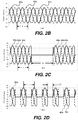
- FIGs. 2B-2D are plots illustrating the difference between continuous and pulsed alternating currents that may be input to an electric machine operating as a motor - as for example, a three-phase induction motor. In each plot, current is plotted on the vertical axis and time is plotted along the horizontal axis.
- Figure 2B illustrates conventional sinusoidal three-phased input current 42a, 42b, and 42c delivered to the electric machine.
- Phase B denoted by curve 42b leads phase A, denoted by 42a by 120 degrees.
- Phase C denoted by curve 42c leads phase B by 120 degrees.
- the sine wave period is ⁇ .
- the three-phased input power 42 is continuous (not pulsed) and has a designated maximum amplitude of approximately 50 amps. It should be appreciated that 50 amps is only a representative maximum current and the maximum current may have any value.
- Figs. 2C and 2D illustrate two examples of different pulsed three-phased currents 44a, 44b, and 44c and 46a, 46b, and 46c that each have a 50% duty cycle and a peak amplitude of approximately 100 amps.
- the period of the base sine wave is ⁇ , however, now the sine wave is modulated on and off.
- the delivered current in Figs. 2C and 2D produces the same average torque as the continuously applied three-phased input current of Fig. 2B .
- the difference between pulsed currents 44a-c and 46a-c is the duration of their respective current pulses and the interleaved "off' periods.
- the current pulses 44a-c are interleaved with "off' periods of equal length.
- the length of each on and off period is 2 ⁇ .
- the current pulses 46a-c and the interleaved "off' periods again have equal duration. In this case the duration is ⁇ /2.
- the duty cycle is 50%.
- the duration of the "on" and "off' time durations is different, i.e. the frequency of the pulsed modulation is different.
- the frequency of the pulsed modulation may vary based on the type of electrical machine used, noise and vibration considerations, current operating rotor speed and other factors.
- Figs. 2C-2D illustrate applications in which the "on" motor drive pulses are evenly spaced while the motor is operated at a steady state desired output level.
- the duty cycle need not be 50%, but can be adjusted to match the desired average output torque.
- the phase of the on/off pulses need not be synchronized with the phase of the applied AC power.
- the relative sizes and/or timing of the motor drive pulses can be varied as long as they average out to deliver the desired average torque.
- power converters When AC electric machines are used in conjunction with a battery or other DC power source/sink (store), power converters (e.g. inverters and rectifiers) will typically be used to convert between DC and AC power.
- inverters are used to convert power received from a DC power supply, such as a battery or capacitor, into AC input power applied to a motor.
- rectifiers are used to convert AC power received from an electric machine operating as a generator into DC output power.
- Some power converters may function as either an inverter or a rectifier depending upon whether the electric machine is functioning as a motor or a generator.
- Fig. 5 is understood to be an inverter energy conversion efficiency map for a 2010 Toyota Prius inverter (i.e., the inverter for the motor represented in Fig. 1 ).
- the energy conversion efficiency of the illustrated inverter is quite good, its efficiency also drops off noticeably in certain regions - most notably at lower torque outputs and at lower motor speeds.
- optimizing control of a motor that is part of an inverter/electric motor combination it is desirable to consider the energy conversion efficiency of the overall inverter/electric motor system as opposed to the energy conversion efficiency of the motor alone.
- a generator that is part of a rectifier/generator system
- it is desirable to consider the energy conversion efficiency of the overall rectifier/generator system as opposed to the energy conversion efficiency of the generator alone.
- the pulsed control of an electric machine will be modeled to account for the efficiencies of any/all of the components that influence the energy conversion during pulsing.
- the battery's power delivery efficiency, cabling losses between components and any other loss factors can be considered in addition to the inverter and motor efficiencies, when determining the motor drive signal that delivers the best energy conversion efficiency.
- the overall energy conversion efficiency of a power converter/electric machine system is a function of the product of the converter conversion efficiency times the electric machine conversion efficiency times the delivery efficiency of other components.
- the parameters of the pulsed drive signal that has the maximum system energy conversion efficiency may be different than the parameters that would provide the best energy conversion efficiency for the motor itself.
- Fig. 6 is a representative energy conversion efficiency map for a combined inverter/AC electric motor. More specifically, Fig. 6 shows the combined efficiency of a Tesla inverter/motor propulsion system. Since the inverter and the electric motor work together, the best overall electric motor system energy conversion efficiency can be optimized by selecting the pulse voltage and corresponding duty cycle based on the combined system energy conversion efficiency map rather than using the electric motor's energy conversion efficiency map alone.
- the energy conversion efficiency map for a particular electric machine system (e.g. a combined power converter/electric machine; battery/power converter/electric machine; etc.) will be more complex than the efficiency map for the electric machine itself.
- One such region is designated 61 in Fig. 6 .
- pulsed operation at the local efficiency peak may be more efficient than continuous operation at those intermediary output levels.
- the motor can be pulsed at the level of the local efficiency peak to deliver such intermediary torque outputs.
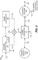
- Fig. 3 illustrates a control architecture suitable for controlling an electric machine in the described manner.
- the system 100 includes a machine controller 110, a pulse controller (pulse generator) 120, a power supply/sink 130, a power controller/converter 140, and an electric machine 160.
- the pulse controller 120 is responsible for controlling/directing the timing of the pulsing of electric machine 160 when pulsed operation is called for.
- the pulse controller is shown as a component that is separate from the machine controller 110 to facilitate explanation of its function.
- the pulse controller may be implemented as part of the machine controller 110, as a separate component, as part of power controller/converter 140 or in other appropriate forms.
- the machine controller When the electric machine 160 is operated as a motor, the machine controller functions as a motor controller, and the power controller/converter 140 is responsible for converting power 132 received from power supply 130 to a form that is suitable for driving the motor 160. Conversely, when the machine 160 is operated as a generator, the machine controller 110 functions as a generator controller and the power controller/converter 140 converts power received from the generator to a form suitable for delivery to the power sink 130.
- the power controller 140 can conceptually take the form of a switch or logical multiplier that simply turns the motor on and off to facilitate the desired pulsing.
- the power supply/sink 130 can take any suitable form.
- the power supply/sink may take the form of a battery or a capacitor.
- the source may be a power grid (e.g., "wall power"), a photovoltaic system, or any other available source.
- the sink may be an electrical load (such as an electrically operated machine or appliance, a building, a factory, a home, etc.), a power grid or any other system that uses or stores electrical power.
- the power controller/converter 140 can also take a wide variety of different forms. When the power supply/sink 130 is a DC power supply and the electric machine 160 is an AC motor, the power controller/converter 140 can take the form of an inverter. Conversely, when the power supply/sink 130 is a DC power sink and the electric machine 160 is an AC generator, the power controller/converter 140 can take the form of a rectifier. When both the power supply/sink 130 and the electric machine are AC components, the power controller/converter 140 may include a bidirectional or 4 quadrant power converter.
- the requested output is labeled 113
- the torque delivered or received by the electric machine is labeled 161
- the motor/generator speed is labeled 164.
- the machine controller 110 includes a data structure 115 (as for example a lookup table) that serves as a pulsed operation map that defines the operating region in which pulsed motor control is desired and/or appropriate as well as the specific duty cycles that are appropriate for specific operating conditions.
- the duration and nature of the pulses used to drive the motor can be determined/generated in a wide variety of manners.
- PWM pulse width modulation
- logical multiplier 123 is shown as multiplying a pulsed control signal 124 times a power level signal 119 output by machine controller 110 to create a power converter control signal 128. It should be appreciated that the logical multiplier 123 is shown for the purposes of explanation and in practice, the function of the multiplier 123 can be accomplished by the machine controller 110, by the power converter 140, or in other suitable manners. For example, in some embodiments, the machine controller 110 may simply set the output of the power converter 140 to zero during the "off' phases of the duty cycle and to the desired operational output level (e.g., the most efficient output level for the current machine speed) during the "on" phases of the duty cycle.
- the desired operational output level e.g., the most efficient output level for the current machine speed
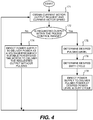
- Fig. 4 illustrates a control flow that may be performed by machine controller 110 to cause the electric machine 160 to efficiently deliver a desired torque.
- the electric machine 160 functions as a motor
- the power supply/sink 130 acts as a power supply and the machine controller 110 functions as a motor controller.
- the motor controller 110 receives the currently requested motor output 113 and any required motor state information such as the current motor speed 164 as represented by block 171.
- the motor controller 110 determines whether the requested output is within the pulsed control range as represented by decision block 172.
- This decision can be made in any desired manner.
- a look-up table 115 or other suitable data structure can be used to determine whether pulsed control is appropriate.
- a simple lookup table may identify a maximum torque level at which pulsed control is appropriate for various motor speeds.
- the current motor speed may be used as an index to the lookup table to obtain a maximum torque level at which the pulsed control is appropriate under the current operating conditions.
- the retrieved maximum torque value can then be compared to the requested torque to determine whether the requested output is within the pulse control range.
- the lookup table 115 may provide additional information such as the desired duty cycle for pulsed operation based on the current operating conditions.
- the motor speed and the torque request may be used as indices for a lookup table with each entry in the lookup table indicating the desired duty cycle with interpolation being used to determine an operational duty cycle when the actual torque and/or motor speeds are between the index values represented in the table.
- the power converter 140 is directed to deliver power at a preferred output level - which would typically (but not necessarily) be at or close to the maximum efficiency operating level for the current motor speed.
- the motor ideally outputs zero torque.
- the timing of the pulsing is controlled by pulse controller 120 as will be discussed in more detail below.
- the motor controller 110 determines the desired output level (block 175) and the desired duty cycle (block 176) for pulsed operation at the current motor speed (which is preferably at or close to the system's maximum efficiency energy conversion output level at the current motor speed - although other energy efficient levels can be used as appropriate).
- the motor controller and the pulse controller then direct the power converter to implement the desired duty cycle (block 178) at the designated power level.
- this may be accomplished by effectively turning the power supply on and off at a relatively high frequency such that the fraction of the time that power is supplied to the motor corresponds to the desired duty cycle, and the power level corresponds to the preferred output level.
- the "off' portion of the duty cycle may be implemented by directing the power controller/converter 140 to drive the motor to deliver zero torque.
- the frequency at which the power is pulsed is preferably determined by the machine controller 110 or the pulse controller 120.
- the pulsing frequency can be fixed for all operation of the motor, while in others it may vary based on operational conditions such as motor speed, torque requirements, etc.
- the pulsing frequency can be determined through the use of a look-up table.
- the appropriate pulsing frequency for current motor operating conditions can be looked up using appropriate indices such as motors speed, torque requirement, etc.
- the pulsing frequency is not necessarily fixed for any given operating conditions and may vary as dictated by the pulse controller 120. This type of variation is common when using sigma delta conversion in the determination of the pulses as discussed below.
- the pulsing frequency may vary proportionally as a function of motor speed, at least in some operating regions of the motor.
- Fig. 4 illustrates some of the steps sequentially to facilitate a clear understanding of the functionality provided, it should be understood that many of the steps can be combined and/or reordered in practice.
- the entries in a multi-dimensional lookup table 115 that uses requested output 113 and current electric motor speed 164 as indices may indicate both the preferred output level and the duty cycle that is appropriate for current operation.
- a value stored in the lookup table can optionally be used to indicate that pulsing is not desired.
- a value stored in the lookup table can optionally be used to indicate that pulsing is not desired.
- a wide variety of other conventions and data structures can be used to provide the same information.
- the pulsed control table can be incorporated into a larger table that defines operation at all levels such that the operational flow is the same regardless whether conventional or pulsed control is desired with the conventional control merely being defined by a duty cycle of 1 and the appropriate motor input power level, and the pulsed control being defined by a smaller duty cycle and use of the preferred motor input power level.
- the machine controller described herein may be implemented in a wide variety of different manners including using software or firmware executed on a processing unit such as a microprocessor, using programmable logic, using application specific integrated circuits (ASICs), using discrete logic, etc. and/or using any combination of the foregoing.
- a processing unit such as a microprocessor, using programmable logic, using application specific integrated circuits (ASICs), using discrete logic, etc. and/or using any combination of the foregoing.
- the duration and nature of the pulses used to drive the motor can be determined/generated in a wide variety of manners.
- One relatively simple approach is to use a pulse width modulation (PWM) controller as the pulse controller 120.
- PWM pulse width modulation
- pulse width modulation is commonly used in certain types of motor control, including AC electric motor control and DC brushless motor control, but such pulse width modulation is used at a very different location in the control scheme.
- an AC induction motor is powered by a battery (which provides DC power)
- an inverter is typically used to facilitate the conversion of DC power to AC power.
- a PWM controller (not shown) is used as part of the inverter controller to control the amplitude of the AC signal that is generated by the inverter. Continuous AC power generated by the inverter is then supplied to the electric motor at the desired frequency and amplitude.
- PWM controllers are similarly used in brushless DC motors to control the amplitude of the continuous signal that is supplied to the motor.
- the pulsed power utilized herein is quite different. Specifically, power converter 140 is controlled to cyclically switch between producing a high efficiency torque output (e.g. the peak efficiency torque) and no torque in the electric machine 160 as discussed above with reference to Figs 2A-2D . In an induction motor, this results in the magnetic flux in the motor windings effectively dropping to zero.
- a high efficiency torque output e.g. the peak efficiency torque
- the period for each cycle during pulsed operation may vary widely based on the design needs and the nature of the controlled system ranging from microseconds to tenths of a second or longer. A variety of factors will influence the choice of the cycle period. These include factors such as the capabilities and characteristics of the motor, the transitory effects associated with switching, potential NVH (noise, vibration and harshness) concerns, the expected operational loads, etc.
- the pulsing frequency selected for any particular application will involve a tradeoff including factors such as NVH considerations, required responsiveness of the electric machine, efficiency loss associated with pulsing, etc. For example, in some automotive applications, pulsing frequencies on the order of 20 Hz-1000 Hz are believed to work well.
- a sigma-delta converter 190 is used as the pulse generator 120.
- a characteristic of sigma delta control is that it facilitates noise shaping and tends to reduce/eliminate idle tones and push noise to higher frequencies.
- noise is randomized and/or spread to frequencies that are above the limits of human perception, it is less of a concern since any such noise and/or vibration is not bothersome to the users of the motor. Therefore, in the context of an automotive electric motor application, use of sigma delta control tends to reduce the likelihood of vehicle occupants perceiving noise or vibrations due to the pulsed motor control.
- first order sigma delta converters may be used as sigma delta converter 190 and the sigma delta converters may utilize a variety of different feedback schemes.
- first order sigma delta conversion works well.
- One particularly desirable feature of using a first order sigma delta converter is that the controller is inherently stable.
- higher order sigma delta converters may be used (e.g., sigma delta converters that utilize a higher number of integrators than a first order sigma delta converter).
- third order sigma delta converters as for example converters using the Richie architecture
- higher order sigma delta converters may be used.
- the sigma delta converters may be implemented algorithmically, digitally, using analog components and/or using hybrid approaches.
- the sigma delta converter may be implemented on a processor, on programmable logic such as an FPGA, in circuitry such as an ASIC, on a digital signal processor (DSP), using analog, digital and/or hybrid components, or any/or using other suitable combinations of hardware and/or software.
- the sigma delta controller may utilize sample data sigma delta, continuous time sigma delta, differential sigma delta, or any other suitable sigma delta implementation scheme.
- the first order sigma-delta converter 200 includes a difference amplifier 201, an integrator 203, and a comparator 205.
- the difference amplifier 201 amplifies the difference between an input signal 209 and a feedback signal 212 and outputs a difference signal 216 which is fed to integrator 203.
- Integrator 203 integrates the difference signal and outputs an integrator output signal 217 which is fed to comparator 205.
- the comparator 205 acts as a one-bit quantizer and outputs a pulsed (high/low) digital control signal 220 that is representative of the input signal 209.
- the one-bit control signal 220 outputted from the comparator 216 is generated by comparing the output of the integrator 203 with a reference voltage.
- the output is effectively a string of ones and zeros that is outputted at the frequency of the sigma delta converter's clock.
- the low signal is treated as a request for zero power from the power supply and the high signal is treated as a request for the most efficient (or other designated) power level for the current motor speed.
- the clock signal 226 for the sigma delta converter (and thus the output stream of the comparator 205) have a frequency that is many times the expected frequency of the rate of change of the input signal 209, to provide good resolution and oversampling of the input signal.
- clock frequencies on the order of 100 kHz to 1 MHz or higher work well for automotive type applications where the input signal (which is generally based on the driver's torque request - e.g. the accelerator pedal) tends to vary at rates of less than 5 Hz. That is, the output of the comparator 205 is sampled at a rate of at least 100 kHz - 1 MHz (although both higher and lower sampling rates may be used in various embodiments).
- the clock signal 226 provided to the comparator 216 may come from any suitable source.
- the clock signal 226 is provided by a crystal oscillator.
- the comparator 205 can be configured to enforce desired constraints on the pulsing (which is sometimes referred to herein as performing as a functionally intelligent comparator).
- the comparator can be constrained to define minimum and/or maximum "on" times, minimum (and/or maximum) "off' times etc. as will be appreciated by those familiar with advanced sigma delta control. Such constraints can be helpful to ensure that the pulsing is performed within desired frequency and "on" pulse length parameters.
- more advanced constraints can be imposed by the comparator. For example, if desired, pulse cycle dither 223 can be added to the comparator.
- the anti-aliasing functionality can be provided as part of the sigma-delta control circuit or it may be provided as an anti-aliasing filter that precedes the sigma delta control circuit or it may be provided in any other suitable form.
- the first integrator provides the anti-aliasing functionality. That is, it effectively acts as a low pass filter.
- a variable clock that is based on motor speed may be used instead of a fixed clock.
- a variable clock that is based on motor speed is diagrammatically illustrated in the sigma delta converter of Fig. 8 which uses a variable clock that is based on motor speed.
- the clock signal is configured to vary proportionally with motor speed.
- the use of a variable speed clock when the motor is operating at speed has the advantage of ensuring that the output of the comparator is better synchronized with the motor speed. This, in turn, can help simplify the overall design of the converter.
- the clock can readily be synchronized with the motor speed by utilizing a phase locked loop 229 that is driven by an indication of motor speed (e.g., a tachometer signal).
- a multiplier 231 may then be used to multiply the motor speed signal 164 to attain the desired sampling rate.
- the multiplication of the motor speed may vary widely based on the needs of any particular system. By way of example, frequency multiplication on the order of 10 to 1,000,000 times, as for example 10,000 times are appropriate in some applications. In another example, sigma delta clock rates on the order of 1 kHz to several hundreds of kilohertz are believed to be suitable for many automotive applications.
- a challenge of using a motor speed based variable clock approach is that it doesn't work particularly well when the motor is stopped or operating at particularly low motor speeds.
- a fixed clock can be used when the motor is stopped and/or operating a speeds below a designated idle threshold (e.g., below 600 RPM).
- a functionally intelligent comparator may be used that has specified start and stop routines or switches to a different operating mode during low speed operation.
- a non-linear RPM clock may be used for operations at lower speeds.
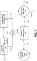
- the sigma delta converter 200 can be configured in several ways.
- the input signal 209 is the desired motor duty cycle.
- the feedback signal 212 is the pulsed digital control signal 220, which corresponds to pulsed control signal 124 from Fig. 7 .
- the pulsed control signal 220 represents the desired motor duty cycle.
- the input signal 209 can be considered to be representative of a desired torque or a desired torque fraction and the feedback signal can be based on the torque output of the motor 161 instead of the pulsed digital control signal 220.
- the feedback is more representative of the actual torque output of the motor than the pulsed control signal 220, since it accounts for any potential torque losses or inefficiencies due to switching the power supply and motor back and forth between the zero and most efficient (or other desired) operational states.
- the feedback signal 212 may be a scaled combination of the pulsed control signal 220 and the torque output of the motor 161.
- differently scaled feedback can be provided to the different integrators as appropriate for the desired adaptive control using the pulsed control signal, the motor torque output or both as the feedback sources.
- first order sigma delta converters are helpful in pushing noise to higher frequencies.
- first order sigma delta conversion is not immune to the generation of idle tones - which can be the source of unwanted noise or vibration.
- One way to help minimize or eliminate idle tones is to add dither to the system.
- Such dither can be added at numerous locations in the system.
- optional pseudo random dither generator 223 may provide an optional dither signal 224 as an additional input to the difference amplifier 201.
- the dither may instead be injected at other locations in the sigma delta converter 200, as for example as an additional input to the comparator 205.
- Higher order sigma delta converters are less susceptible to idle tones and therefore there is less of a benefit to adding dither to such systems. Accordingly, dither would typically not be used in such systems (although it can be used).
- pulse width modulation and sigma delta conversion are used to generate the pulsed control signal.
- Pulse width modulation and sigma delta conversion are two types of converters that can be used to represent the input signal. Some of the described sigma delta converters exhibit oversampled conversion and in various alternative embodiments, other oversampled converters can be used in place of sigma delta conversion. In still other embodiments, other types of converters can be used as well. It should be appreciated that the converters may employ a wide variety of modulation schemes, including various pulse height or pulse density modulation schemes, code division multiple access (CDMA) oriented modulation or other modulation schemes may be used to represent the input signal, so long as the pulse generator is adjusted accordingly.
- CDMA code division multiple access
- switched reluctance motors are powerful motors that are relatively inexpensive when compared to similarly sized induction motors.
- switched reluctance motors tend to be noisy and susceptible to vibrations due to their switching, which make them unsuitable for use in a number of applications.
- a feature of sigma delta conversion is its ability to shape noise and to push noise to frequencies that are less (or not) bothersome to humans.
- controlling switched reluctance motors in a pulsed manner using sigma-delta or other noise shaping conversion techniques has the potential to make the use of switched reluctance motors practical in a number of applications for which they are not currently used.
- a general goal of the pulsed motor control is to operate (power) the motor at its most efficient level for the current motor speed during the motor "on” periods and to cut-off power (provide zero torque) during the motor "off' periods.
- the power transitions between the motor power "on” and “off' states would be discrete steps.
- Fig. 9A illustrates the idealized/desired motor drive power for pulsed motor control at a duty cycle of 50%.
- the transitions between the "on” pulses 302 and the "off' periods 304 are ideally steps.
- Fig. 9B The actual response of a particular motor will vary widely with the electrical characteristics of the motor. In general, the motor's actual input power will rise and fall somewhat exponentially in response to a step change in the commanded motor drive power. The nature of the rise and fall is diagrammatically illustrated in Fig. 9B . As seen therein, there is a ramp-up period (rise time) 306 required for the power signal to actually rise from zero to the desired "on" power level and a ramp-down period (fall time) 308 required for the power signal to actually fall from the "on" power level down to zero.
- the motor continues to be driven during the power ramp-up and ramp-down periods.
- the motor operates less efficiently during those periods in a varying manner as can readily be understood with reference to Fig. 1 .
- the motor efficiency will drop as the operating power drops from the maximum efficiency line 16 towards zero, with the energy conversion efficiency getting noticeably worse as the power level approaches zero.
- the pulse distortion represented by the power ramp-up and ramp-down periods detract from the efficiency gains that can be gained by the described pulsed operation.
- the smaller the ratio of the rise/fall times to the pulse length the less the transitory switching effects impact the motor's energy conversion efficiency during pulsing.
- the transitory effects shown in Fig. 9B are shown for the purpose of illustrating the nature of the problem and is not necessarily reflective of the rise/fall times associated with operation of any particular motor.
- the relative scale of the rise time to the pulse length ratio can vary widely based on the available power supply voltage and the characteristics of the motor used (which primarily dictates the rise and fall times), the frequency of the pulsing (which is primarily dictated by the control scheme used) and the pulse width (which is dictated by the control scheme and motor load). If the pulsing is slow compared to the motor response, the rise/fall times may be a tiny fraction of the pulse width and the transitory switching effects may have a minimal impact on motor performance.
- a resonant capacitor based on motor inductance is employed.
- Resonant capacitors can be used to reduce the power rise and fall times by factors of 100 or more (often substantially more), thus they can significantly reduce the transitory switching effects associated with pulsed operation. Therefore, it should be appreciated that motors that are designed with pulsed control in mind or modified to improve the transient response of the motor to power pulses can benefit even more from pulsed operation than existing motors.
- boost converters and/or buck-boost converters may be used to significantly reduce the rise and fall times associated with switching between the "on" and "off' motor states.
- a boost converter can charge a boost capacitor (sometimes referred to herein as a kick-start capacitor) to a voltage higher than the motor's input voltage. Each time the motor is pulsed on, the kick-start capacitor applies the higher voltage to the motor which can shorten the rise time significantly.
- a boost capacitor sometimes referred to herein as a kick-start capacitor
- a buck-boost converter can be used to charge a buck-boost capacitor.
- the buck-boost capacitor can store energy from the motor winding's magnetic field, which can significantly shorten the pulse's transient fall time
- the voltage charge levels and capacitances of the boost and buck-boost capacitors respectively are chosen appropriately for the motor and its inductive and resistive characteristics to shorten the transient rise/fall times associated with pulsing the motor on and off respectively.
- the respective capacitances and charge voltage levels of the boost and buck-boost capacitors are also selected to maximize overall motor efficiency during pulsing considering all aspects including inefficiencies associated with the transients themselves and the effects of any overshoot that may occur due to use of the boost and buck-boost converters. Since the boost and buck-boost capacitors are used to improve transient response, they may each be opportunistically recharged in the periods between their respective usages - as for example during the motor off periods.
- the electromagnetic field contains a certain amount of energy stored in the magnetic. If the motor is simply turned off, the stored energy will dissipate, which results in loss of the energy that was present within the magnetic field. Any such energy losses reduce the overall system efficiency.
- Some of that field energy can be recovered by affirmatively controlling the off transient of a motor to deliver zero torque during the "off' cycles rather than simply cutting the supply of current to the motor to effective turn the motor off.
- the power drawn from the generator can be controlled to efficiently manage the capture of the stored energy built up in the motor during the "on" cycles.
- Fig. 11 illustrates a power converter/controller that incorporates transient control circuitry 343 (which may include resonant circuits, boost and buck-boost circuits and/or other transient response improving circuits together, alone or in any appropriate combination).
- machine controller 310 directs pulsed control of power converter/controller 340 - which in turn controls electric machine 160.
- the transient control circuitry 343 is incorporated into the power converter 340 itself.
- the transient control circuitry may be provided as an add-on unit that is placed between the power converter 340 and the motor/generator or incorporated into the motor/generator itself to accomplish the same functionality (placement not shown).
- pulsed machine control can be utilized in a wide variety of different applications to improve the energy conversion efficiency of a wide variety of different types of electric motors and generators. These include both AC and DC motors/generators.
- a few representative types of electric machines that may benefit from the described pulsing include both asynchronous and synchronous AC electric machines including: Induction machines (IM); switched reluctance machines (SMR); Synchronous Reluctance machines (SynRM); Permanent Magnet Synchronous Reluctance machines (PMaSynRM); Hybrid PMaSynRMs; Externally Excited AC Synchronous machines (SyncAC); Permanent Magnet Synchronous machines (PMSM); Eddy current machines; AC linear machines; AC and DC mechanically commutated machines; axial flux motors; etc.
- Representative DC electric machines include brushless, electrically excited, permanent magnet, series wound, shunt, brushed, compound and others.
- control and energy conversion efficiency of the various types of electric motors and generators vary significantly, most electric machines are designed to operate over a range of operating conditions and their energy conversion efficiency will vary over that operating range - often significantly.
- control principles described herein can be applied to any type of electric machine to improve the electric machine's efficiency if the electric machine's operating range includes regions below the equivalent of the maximum efficiency curve illustrated in Fig. 1 .
- efficiency gains can be attained by designing an electric machine with pulsed operation in mind.
- Some motor designs utilize windings on both the rotor and stator to generate the motor flux, while others use permanent magnets on either the rotor or stator to contribute to the motor flux.
- Motors that incorporate permanent magnets will have flux at zero torque and therefore will typically have core losses when rotating and produce a back EMF (BEMF) in excess of the supply voltage. In such applications it will often be desirable to provide a small current to the motor during the "torque off' periods in order to maintain zero torque. It should be appreciated that the need to supply current during the "no torque" periods reduces the overall efficiency associated with pulsing and therefore should be considered when determining which operating ranges can benefit from pulsing.
- the losses associated with switching and supplying current during the torque off periods may exceed the efficiency gains associated with pulsing, thereby reducing (or entirely eliminating) the operating range in which pulsed operation is desirable.
- many electric machines that incorporate permanent magnets will have operating regions in which the machine's overall efficiency can be improved through the use of pulsing.
- IPMSM Internal Permanent Magnet Synchronous Motors
- the operating region most suitable for pulsed operation are expected to be operating speeds below (or near to) the threshold speed at which field weakening is required.
- Electrics motors used for vehicle propulsion are commonly referred to as traction motors.
- traction motors In the automotive space there have been significant efforts recently to utilize traction motors alone or in combination with internal combustion engines (hybrids) to drive a vehicle.
- hybrids internal combustion engines
- asynchronous motors and three phase induction motors are most commonly used in automotive applications - both of which are good candidates for the described pulsed motor control.
- Automotive applications are notorious for the very wide range of operating conditions that the motor is expected to operate under - from low speed high torque demands to high speed low torque demands and everything in between.
- the motor Under most driving conditions (i.e., during the significant majority of many drive cycles), the motor is asked to produce far less torque than it is capable of at the current motor speed - and indeed most driving occurs in regions where the requested output of the motor is below (often significantly below) the maximum efficiency line 16.
- Fig. 10 The low load nature of typical driving cycles can be seen in Fig. 10 , which plots a series of drive points representing the electric power/torque output of a simulated traction motor/generator running a Federal Test Procedure for a city driving cycle (FTP-75). The drive points are plotted on a Torque/Speed/Efficiency graph. As can be seen in Fig. 10 , a significant portion of the drive cycle requires lower torque as compared to the maximum efficiency curve 16. Thus significant portions of the typical drive cycle are in operating regions that can attain benefits (and often significant benefits) from the described motor control approach. Fig. 10 depicts only those portions of the drive cycle where output torque is required. During some portions of the drive cycle regenerative braking may be used with the electric machine acting as a generator.
- the operational range of the electric motor may be very wide. This is due, in part, to the fact that in most all-electric vehicle applications, the electric motor is coupled to the driven component(s) with a fixed speed ratio. This contrasts with in internal combustion engine powered vehicle, which typically employ an intermediary transmission having variable speed ratios between the engine and the driven component(s). As can be seen fairly clearly seen in Fig. 1 , the "sweet spot" of electric motor operation is often at an intermediate motor speed. When desired, variable gearing can be used to cause the motor to operate in more efficient regions more of the time. Such gearing can readily be provided by a transmission and thus, there are potential advantages to using a transmission in conjunction with the described pulsed motor control.
- the transmission may have a set of gears or may be continuously variable or may have any other suitable form.
- the motor controller or other suitable control component can be arranged to direct operation of the transmission in the desired manner.
- the use of a transmission can be beneficially employed in a wide variety of other (non-vehicle) related applications as well.
- HVAC Heating, Ventilation and Air Conditioning
- motors are used in a wide variety of other applications in which they are operated at less than their optimal efficiency. This can be due to operating over a wide operating range (e.g., under a wide variety of different loads and/or motor speeds) or it can be due to the use of a motor that is oversized (or otherwise not designed specifically) for its application or any of a variety of other reasons. It should be apparent that the described control approach can be beneficial to any of these types of applications.
- pulsing is accomplished by modulating the torque between a higher (energy efficient) torque output level and a zero torque output level.
- a higher (energy efficient) torque output level is believed to be the preferred approach in most pulsed control application, it is expected that there will be circumstances (e.g. specific machines/machine operating region) where it may be preferable to modulate between higher and lower, non-zero torque outputs rather than modulating between high and zero torque.
- High/Low pulsing may have better Noise, Vibration and Harshness (NVH) characteristics that on/off pulsing and thus there may be circumstances where a more desirable tradeoff between energy conversion efficiency and NVH characteristics may be attained by high/low pulsing than by on/off pulsing.
- NSH Noise, Vibration and Harshness
- a high/low pulsing approach may provide better overall energy conversion efficiency than on/off pulsing.
- Motors that incorporate permanent magnets that require field weakening to generate zero torque are particularly good candidates for the use of high-low torque modulation.
- the maximum rated output level is based on steady state operation and often the motor can be driven at higher output levels for brief periods of time without any adverse effects.
- the output level of motor may be pulsed with the "on" levels being higher than the maximum rated continuous output level for steady state operation.
- overdrive pulses there are several potential advantages to using overdrive pulses. For example, in some specific operating circumstances, the energy conversion efficiency of the motor or system (e.g., motor and inverter) at a given motor speed may be higher in certain overdrive regions than in "normal" operating regions, which means that pulsed operation at higher torque or power may be even more efficient.
- the power factor which is the cosine of the angle between the rotating voltage and current vectors.
- the voltage and current should be in phase or have a unity power factor.
- this ideal does not necessarily represent the highest system efficiency point for any given load and speed.
- resistive losses heat the motor windings, which in turn further increases resistive losses, since winding resistivity generally increases with temperature. Resistive losses are non-linear - increasing with at least the square of the current. Therefore, resistive losses tend to have a higher impact on the overall motor efficiency at higher motor output levels - such as the levels used during pulsed operation.
- a rule-of-thumb for electric motor design is that the magnetic losses should approximately equal the resistive losses at the target set point of operation.
- Using the pulsed motor control method described herein may influence the design of or choice of an appropriate motor, since motor operating points below the most efficient operating point will generally not be used. In other words, the motor is driven either at substantially its most efficient operating point or at higher loads. Low load continuous operating need not be considered in the design or selection of the electric motor - which again can help further improve the system overall efficiency.
- magnétique core losses Another factor that contributes to motor inefficiency is sometimes referred to as the magnetic core losses - which relates to magnetic flux oriented losses.
- One loss mechanism is motor winding leakage reactance, which refers to magnetic flux lines that do not link between rotor and stator magnetic elements.
- Another magnetic core loss mechanism relates to hysteresis within magnetic iron cores and are often represented in a BH curve.
- B is the magnetic flux density
- H is the magnetic field strength. They are related by the magnetization of the materials thru which the field passes, which for some motors, is the iron core(s) present in the rotor or stator.
- a motor that is designed specifically for pulsed control can be optimized to mitigate magnetic core losses during pulsed motor operation.
- transient switching losses associated with switching between motor “on” and motor “off' states during pulsing is another factor that impacts the efficiency of the motor during pulsed operation.
- one way to reduce these transient switching losses is to improve (shorten) the motor drive current rise and fall times associated with pulsing the motor on and off.
- Another way to help manage the transient switching losses is to manage the frequency of the pulsing. In general, the lower the switching frequency, the lower the transient switching losses will be. However there is a tradeoff here in that lower frequency switching can sometimes induce noise, vibration and harshness (NVH) that may be undesirable or unacceptable in certain applications.
- NSH noise, vibration and harshness
- the pulsing frequency for any particular motor is preferably selected appropriately considering both motor efficiency and NVH concerns and/or requirements that are relevant to the motors intended application(s).
- the pulsing controllers that have noise shaping capabilities such as sigma delta conversion based pulsing controllers can be very helpful at mitigating NVH impacts associated with pulsed motor control and can therefore be helpful in supporting the use of generally lower switching frequencies.
- the appropriate pulsing frequency for different motors may be very different based on the motor's construction, operating environment and operational range. For some motors, switching frequencies on the order of 10-50 kHz may be appropriate - whereas for other motors much lower switching frequencies, as for example 10-500 Hz range may be more appropriate. Still other electric machines may have switching frequencies between these ranges or above or below either of the stated ranges.
- the most appropriate pulsing frequency for any particular motor will depend on a variety of factors including motor size, on/off transient characteristics, NVH considerations, etc.
- the selection of the desire drive point for any particular motor speed can also have an impact on the switching frequency. More specifically, many motors have relatively flat efficiency curves over a relatively broad operational range. In general, pulsed operation at a torque level that is slightly lower than the optimal efficiency point of continuous operation, can sometimes facilitate switching at a slightly lower frequency, which - depending on the nature of the switching losses - may result in a higher overall motor efficiency during pulsed operation. This emphasizes the point that the desired pulsed operation drive point associated with any particular motor speed is not necessarily the torque level that would be most efficient for continuous motor operation. Rather, in some circumstances, the most energy efficient point for pulsed operation may be slightly different than the most energy efficient point for continuous operation. Furthermore, NVH considerations and/or other operational or control considerations may affect the decision as to the drive point that is deemed appropriate for any particular motor speed.
- the pulse controller may be incorporated into a motor controller or an inverter controller or it may be provided as a separate component.
- the pulse controller may be incorporated into a generator controller or a rectifier controller and in combined motor/generators the pulse controller may be incorporated into a combined motor/generator controller or a combined inverter/rectifier controller.
- the described control functionality may be implemented algorithmically in software or firmware executed on a processor - which may take any suitable form, including, for example, general purpose processors and microprocessors, DSPs, etc.
- the pulse generator or machine controller may be part of a larger control system.
- the described control may be part of a vehicle controller, a powertrain controller, a hybrid powertrain controller, or an ECU (engine control unit), etc. that performs a variety of functions related to vehicle control.
- the vehicle or other relevant controller, etc. may take the form of a single processor that executes all of the required control, or it may include multiple processors that are co-located as part of a powertrain or vehicle control module or that are distributed at various locations within the vehicle.
- the specific functionalities performed by any one of the processors or control units may be widely varied.
- control schemes can be implemented within the pulse controller 120.
- the control schemes may be implemented digitally, algorithmically, using analog components or using hybrid approaches.
- the pulse generator and/or the motor controller may be implemented as code executing on a processor, on programmable logic such as an FPGA (field programmable gate array), in circuitry such as an ASIC (application specific integrated circuit), on a digital signal processor (DSP), using analog components, or any other suitable piece of hardware.
- the described control schemes may be incorporated into object code to be executed on a digital signal processor (DSP) incorporated into an inverter controller (and/or rectifier controller in the context of a generator and/or a combined inverter/rectifier controller).
- DSP digital signal processor
- sigma delta control is used to create the pulsed control signal.
- sigma delta control is one particularly good way to create the pulsed control signal 124, it should be appreciated a variety of other control schemes may be used to create the pulsed control signal in other embodiments.
- the torque modulation is preferably managed in a manner such that NVH that is unacceptable for the intended application is not produced.
- the described pulsed motor control can be used in a wide variety of applications.
- the biggest efficiency gains will typically be seen in motors and generators that are not consistently driven at near their optimal operating efficiency.
- a good example of this is motors/generators that have a wide operational range and are intended for use under widely varying load conditions.
- Another good example is motors that are routinely under driven. For example, it is not uncommon for system designers to use larger motors than are actually required for an application - e.g., using a 100 hp motor when a 50 hp motor would be more than adequate for the assigned tasks. In many cases, the larger motor may run less efficiently at the reduced load and in such circumstances, pulsed control may improve the motors efficiency during use.
Landscapes
- Engineering & Computer Science (AREA)
- Power Engineering (AREA)
- Theoretical Computer Science (AREA)
- Control Of Ac Motors In General (AREA)
- Control Of Electric Motors In General (AREA)
Applications Claiming Priority (5)
| Application Number | Priority Date | Filing Date | Title |
|---|---|---|---|
| US201862644912P | 2018-03-19 | 2018-03-19 | |
| US201862658739P | 2018-04-17 | 2018-04-17 | |
| US201962810861P | 2019-02-26 | 2019-02-26 | |
| EP19772096.4A EP3753100A4 (de) | 2018-03-19 | 2019-03-14 | Steuerung einer gepulsten elektrischen maschine |
| PCT/US2019/022185 WO2019182846A1 (en) | 2018-03-19 | 2019-03-14 | Pulsed electric machine control |
Related Parent Applications (2)
| Application Number | Title | Priority Date | Filing Date |
|---|---|---|---|
| EP19772096.4A Division-Into EP3753100A4 (de) | 2018-03-19 | 2019-03-14 | Steuerung einer gepulsten elektrischen maschine |
| EP19772096.4A Division EP3753100A4 (de) | 2018-03-19 | 2019-03-14 | Steuerung einer gepulsten elektrischen maschine |
Publications (1)
| Publication Number | Publication Date |
|---|---|
| EP3852265A1 true EP3852265A1 (de) | 2021-07-21 |
Family
ID=67904210
Family Applications (2)
| Application Number | Title | Priority Date | Filing Date |
|---|---|---|---|
| EP19772096.4A Pending EP3753100A4 (de) | 2018-03-19 | 2019-03-14 | Steuerung einer gepulsten elektrischen maschine |
| EP21157204.5A Pending EP3852265A1 (de) | 2018-03-19 | 2019-03-14 | Steuerung einer gepulsten elektrischen maschine |
Family Applications Before (1)
| Application Number | Title | Priority Date | Filing Date |
|---|---|---|---|
| EP19772096.4A Pending EP3753100A4 (de) | 2018-03-19 | 2019-03-14 | Steuerung einer gepulsten elektrischen maschine |
Country Status (6)
| Country | Link |
|---|---|
| US (6) | US10742155B2 (de) |
| EP (2) | EP3753100A4 (de) |
| JP (2) | JP7082679B2 (de) |
| KR (2) | KR20240090714A (de) |
| CN (1) | CN111886797A (de) |
| WO (1) | WO2019182846A1 (de) |
Cited By (1)
| Publication number | Priority date | Publication date | Assignee | Title |
|---|---|---|---|---|
| WO2023089509A1 (en) * | 2021-11-17 | 2023-05-25 | The Secretary Of State For Foreign, Commonwealth & Development Affairs | Motor drive |
Families Citing this family (25)
| Publication number | Priority date | Publication date | Assignee | Title |
|---|---|---|---|---|
| US10944352B2 (en) | 2018-03-19 | 2021-03-09 | Tula eTechnology, Inc. | Boosted converter for pulsed electric machine control |
| US11133767B2 (en) | 2018-03-19 | 2021-09-28 | Tula eTechnology, Inc. | Pulsed electric machine control using tables |
| WO2019182846A1 (en) | 2018-03-19 | 2019-09-26 | Tula eTechnology, Inc. | Pulsed electric machine control |
| US11623529B2 (en) | 2018-03-19 | 2023-04-11 | Tula eTechnology, Inc. | Pulse modulated control with field weakening for improved motor efficiency |
| US11427177B2 (en) | 2019-11-20 | 2022-08-30 | Tula eTechnology, Inc. | Pulsed electric machine control using tables |
| CN115699561A (zh) * | 2020-04-21 | 2023-02-03 | 图拉E技术公司 | 用于提高电动机效率的使用磁场削弱的脉冲调制控制 |
| WO2021221852A1 (en) | 2020-04-30 | 2021-11-04 | Tula Etechnology Inc. | Magnetically de-coupled, separately controlled, multiple electric machine assembly for driving a common shaft |
| US20210351733A1 (en) * | 2020-05-05 | 2021-11-11 | Tula eTechnology, Inc. | Pulsed electric machine control |
| US11628730B2 (en) | 2021-01-26 | 2023-04-18 | Tula eTechnology, Inc. | Pulsed electric machine control |
| EP4308405A4 (de) * | 2021-03-15 | 2024-07-10 | Tula Technology Inc | Verfahren zur optimierung von wellenformen für elektromotoren |
| DE102021204156A1 (de) * | 2021-04-27 | 2022-10-27 | BSH Hausgeräte GmbH | Dunstabzugshaube und Verfahren zum Steuern einer Dunstabzugshaube |
| US11794915B2 (en) * | 2021-04-27 | 2023-10-24 | Beta Air, Llc | Method and system for a two-motor propulsion system for an electric aircraft |
| KR20240021165A (ko) | 2021-06-14 | 2024-02-16 | 툴라 이테크놀로지 아이엔씨. | 효율적인 토크 이행을 갖춘 전기 머신 |
| CN117501614A (zh) | 2021-06-28 | 2024-02-02 | 图拉E技术公司 | 电机的选择性相控制 |
| US11557996B1 (en) | 2021-07-08 | 2023-01-17 | Tula eTechnology, Inc. | Methods of reducing vibrations for electric motors |
| US11345241B1 (en) * | 2021-08-12 | 2022-05-31 | Tula eTechnology, Inc. | Method of optimizing system efficiency for battery powered electric motors |
| JP2024533412A (ja) * | 2021-09-08 | 2024-09-12 | トゥラ イーテクノロジー,インコーポレイテッド | 波形の整数倍に基づく電気機械トルク調節 |
| WO2023064226A1 (en) * | 2021-10-11 | 2023-04-20 | Tula eTechnology, Inc. | Pulsed control of multiple electric machines |
| WO2023069131A1 (en) | 2021-10-18 | 2023-04-27 | Tula eTechnology, Inc. | Mechanical and electromechanical arrangements for field-weakening of an electric machine that utilizes permanent magnets |
| WO2023069934A1 (en) * | 2021-10-22 | 2023-04-27 | Atieva, Inc. | Ceasing transistor toggling in permanent magnet motor when zero motor torque is demanded |
| WO2023150354A1 (en) * | 2022-02-07 | 2023-08-10 | Tula Etechnology Inc. | Pulsed electric machine control |
| US12077306B2 (en) | 2022-06-29 | 2024-09-03 | Beta Air Llc | Apparatus and method for optimizing motor performance in an electric aircraft |
| US11888424B1 (en) * | 2022-07-18 | 2024-01-30 | Tula eTechnology, Inc. | Methods for improving rate of rise of torque in electric machines with stator current biasing |
| US20240025271A1 (en) * | 2022-07-21 | 2024-01-25 | GM Global Technology Operations LLC | Low loss electric drive speed guideline system for electric vehicles |
| CN117584755B (zh) * | 2023-12-21 | 2024-09-13 | 中国重汽集团济南动力有限公司 | 多电机电驱桥制动能量回收扭矩分配方法、装置及车辆 |
Citations (4)
| Publication number | Priority date | Publication date | Assignee | Title |
|---|---|---|---|---|
| US20090146615A1 (en) * | 2004-11-16 | 2009-06-11 | Volkswagen Aktiengesellschaft | Hybrid Motor Vehicle and Method for Controlling Operation of a Hybrid Motor Vehicle |
| US8099224B2 (en) | 2008-07-11 | 2012-01-17 | Tula Technology, Inc. | Internal combustion engine control for improved fuel efficiency |
| EP2605398A1 (de) * | 2011-10-17 | 2013-06-19 | Panasonic Corporation | Motorantriebssystem und steuerungsverfahren dafür |
| US20180216551A1 (en) | 2008-07-11 | 2018-08-02 | Tula Technology, Inc. | Internal combustion engine control for improved fuel efficiency |
Family Cites Families (177)
| Publication number | Priority date | Publication date | Assignee | Title |
|---|---|---|---|---|
| US4441043A (en) | 1980-11-24 | 1984-04-03 | Decesare Dominic | Compound interaction/induction electric rotating machine |
| JPS6189144A (ja) | 1984-10-08 | 1986-05-07 | Nissan Motor Co Ltd | 自動車用故障診断装置 |
| JPH07106073B2 (ja) * | 1989-04-19 | 1995-11-13 | 株式会社日立製作所 | モータの減速装置およびこれに用いられるモータ駆動回路あるいはミシンの制御装置 |
| US5099410A (en) | 1990-11-13 | 1992-03-24 | Wisconsin Alumni Research Foundation | Single phase ac power conversion apparatus |
| JPH05153705A (ja) | 1991-11-28 | 1993-06-18 | Hitachi Ltd | 電気自動車 |
| GB9225090D0 (en) | 1992-12-01 | 1993-01-20 | Univ Cardiff | Performance enhancement of single phase switched motor by d c link voltage |
| JP3290481B2 (ja) | 1992-12-03 | 2002-06-10 | 東芝キヤリア株式会社 | 冷凍サイクル制御装置 |
| US5325028A (en) | 1993-03-26 | 1994-06-28 | Storage Technology Corporation | System and method for magnetic tape leader block extraction |
| US6424799B1 (en) * | 1993-07-06 | 2002-07-23 | Black & Decker Inc. | Electrical power tool having a motor control circuit for providing control over the torque output of the power tool |
| US6121740A (en) | 1994-06-27 | 2000-09-19 | Ford Global Technologies, Inc. | Control of regeneration energy from an electric motor |
| JP3333793B2 (ja) | 1994-09-22 | 2002-10-15 | サンデン株式会社 | ブラシレスモータ装置 |
| US5627438A (en) | 1995-01-25 | 1997-05-06 | Barrett; Robert D. | Pulsing control for an inertial drive system for a multi-motor binary array vehicle |
| JPH0984208A (ja) | 1995-09-14 | 1997-03-28 | Denso Corp | 電気自動車用制御装置 |
| JP3716534B2 (ja) * | 1997-02-27 | 2005-11-16 | 日産自動車株式会社 | モータ制御装置及び電動車両 |
| US6605912B1 (en) | 1998-06-25 | 2003-08-12 | Delphi Technologies, Inc. | Method for controlling a permanent magnet motor |
| FI110040B (fi) | 1998-10-07 | 2002-11-15 | Abb Industry Oy | Vaihtosuuntaajajärjestely |
| US6483218B1 (en) | 1999-05-20 | 2002-11-19 | Alex Petrinko | Brushless electric exciter for dynamoelectric machines |
| JP2001010518A (ja) | 1999-06-25 | 2001-01-16 | Honda Motor Co Ltd | 車両用操舵制御装置 |
| US6493204B1 (en) | 1999-07-09 | 2002-12-10 | Kelsey-Hayes Company | Modulated voltage for a solenoid valve |
| US7453174B1 (en) | 1999-08-10 | 2008-11-18 | American Superconductor Corporation | Superconducting electric motor |
| US6291960B1 (en) | 2000-03-22 | 2001-09-18 | Ford Global Technologies, Inc. | Pulse width modulated motor control system and method for reducing noise vibration and harshness |
| JP2001317353A (ja) | 2000-05-11 | 2001-11-16 | Nissan Motor Co Ltd | 車両用モータファンの制御方法及び装置 |
| DE10048826B4 (de) | 2000-09-29 | 2012-03-01 | Robert Bosch Gmbh | Verfahren und Vorrichtung zur Erfassung alterungsbedingter Veränderungen von technischen Systemen wie Elektromotoren |
| US6528967B2 (en) | 2000-10-17 | 2003-03-04 | Vscf, Inc. | Permanent magnet brushless electric motor system and method of using same |
| WO2003036787A1 (en) | 2001-10-25 | 2003-05-01 | Koninklijke Philips Electronics N.V. | Commutation of sensorless direct-current motors |
| US6906485B2 (en) | 2001-11-05 | 2005-06-14 | Seagate Technology Llc | Spindle motor control using a current profile to taper current transitions |
| JP3672866B2 (ja) | 2001-12-04 | 2005-07-20 | 松下電器産業株式会社 | モータ駆動装置およびモータ駆動方法 |
| JP3651595B2 (ja) | 2001-12-13 | 2005-05-25 | 株式会社東芝 | 洗濯機のインバータ装置及び洗濯乾燥機のインバータ装置 |
| US6823033B2 (en) * | 2002-03-12 | 2004-11-23 | Qualcomm Inc. | ΣΔdelta modulator controlled phase locked loop with a noise shaped dither |
| US7034422B2 (en) | 2002-05-24 | 2006-04-25 | Virginia Tech Intellectual Properties, Inc. | Radial-axial electromagnetic flux electric motor, coaxial electromagnetic flux electric motor, and rotor for same |
| US6829556B2 (en) | 2003-02-13 | 2004-12-07 | General Electric Company | Method and system for detecting incipient failures in a traction system |
| US6954044B2 (en) * | 2003-12-11 | 2005-10-11 | Honeywell International Inc. | Electric motor with speed control |
| WO2006131993A1 (ja) | 2005-06-10 | 2006-12-14 | Toyota Jidosha Kabushiki Kaisha | 回転電機 |
| US7259664B1 (en) | 2004-06-16 | 2007-08-21 | Chahee Peter Cho | Sensorless fuel level and oil change indicators |
| US7558655B2 (en) | 2004-09-10 | 2009-07-07 | Ford Global Technologies, Llc | Prognostic method and system for hybrid and electric vehicle components |
| JP4254738B2 (ja) | 2005-03-31 | 2009-04-15 | 株式会社デンソー | 車両用発電機の発電制御装置 |
| DE102006009250A1 (de) | 2005-04-20 | 2006-11-02 | Siemens Ag | Sattelförmige Spulenwicklung unter Verwendung von Supraleitern und Verfahren zu ihrer Herstellung |
| US7190143B2 (en) | 2005-05-27 | 2007-03-13 | Rockwell Automation Technologies, Inc. | Pulse width modulation (PWM) rectifier with variable switching frequency |
| US7411801B2 (en) | 2005-12-14 | 2008-08-12 | Gm Global Technology Operations, Inc. | Method and apparatus for controlling voltage linearity of voltage source inverters |
| EP1982406A1 (de) | 2006-02-10 | 2008-10-22 | The Timken Company | Elektromotor mit feldschwächung |
| JP4736875B2 (ja) | 2006-03-14 | 2011-07-27 | 株式会社デンソー | ファンモータ駆動装置及びファンモータ駆動方法 |
| CN100355196C (zh) | 2006-03-29 | 2007-12-12 | 北京航空航天大学 | 小电枢电感高速永磁无刷直流电动机无位置传感器控制系统 |
| JP4802849B2 (ja) * | 2006-05-09 | 2011-10-26 | トヨタ自動車株式会社 | モータ駆動装置 |
| US7854683B2 (en) | 2006-06-08 | 2010-12-21 | Chrysler Group Llc | Torque converter clutch control |
| JP2008079686A (ja) | 2006-09-26 | 2008-04-10 | Hitachi Appliances Inc | 洗濯機および洗濯乾燥機 |
| JP4882053B2 (ja) | 2006-11-08 | 2012-02-22 | 国立大学法人東京海洋大学 | 超電導回転電機駆動制御システム |
| JP5167631B2 (ja) | 2006-11-30 | 2013-03-21 | 株式会社デンソー | モータの制御方法及びそれを利用するモータ制御装置 |
| US7479723B2 (en) * | 2007-01-30 | 2009-01-20 | Gm Global Technology Operations, Inc. | Permanent magnet machine rotor |
| US20110089774A1 (en) * | 2007-01-30 | 2011-04-21 | Kramer Dennis A | Transverse flux motor with integral cooling |
| JP2008285075A (ja) | 2007-05-18 | 2008-11-27 | Toyota Motor Corp | 車両および車両の故障診断方法 |
| US8072115B2 (en) | 2007-06-07 | 2011-12-06 | Novatorque, Inc. | Foil coil structures and methods for winding the same for axial-based electrodynamic machines |
| US20090045691A1 (en) | 2007-08-17 | 2009-02-19 | Kura Laboratory Corporation | Field controllable rotating electric machine system with magnetic excitation part |
| JP4452735B2 (ja) | 2007-09-05 | 2010-04-21 | 本田技研工業株式会社 | 昇圧コンバータの制御装置および制御方法 |
| US7616466B2 (en) | 2007-09-12 | 2009-11-10 | Gm Global Technology Operations, Inc. | Three phase inverter with improved loss distribution |
| US8860356B2 (en) | 2007-09-18 | 2014-10-14 | Kabushiki Kaisha Toshiba | Variable magnetic flux motor drive system |
| US8084972B2 (en) | 2007-11-16 | 2011-12-27 | Honeywell International Inc. | Dual lane control of a permanent magnet brushless motor using non-trapezoidal commutation control |
| US7888905B2 (en) | 2008-01-11 | 2011-02-15 | GM Global Technology Operations LLC | Method and system for controlling a power inverter in electric drives |
| US7791521B2 (en) | 2008-04-01 | 2010-09-07 | Silicon Laboratories, Inc. | System and method of changing a PWM power spectrum |
| US7577511B1 (en) | 2008-07-11 | 2009-08-18 | Tula Technology, Inc. | Internal combustion engine control for improved fuel efficiency |
| US8131447B2 (en) * | 2008-07-11 | 2012-03-06 | Tula Technology, Inc. | Internal combustion engine control for improved fuel efficiency |
| US8453770B2 (en) | 2009-01-29 | 2013-06-04 | Tesla Motors, Inc. | Dual motor drive and control system for an electric vehicle |
| US7808415B1 (en) | 2009-03-25 | 2010-10-05 | Acco Semiconductor, Inc. | Sigma-delta modulator including truncation and applications thereof |
| WO2010137162A1 (ja) * | 2009-05-29 | 2010-12-02 | トヨタ自動車株式会社 | 交流電動機の制御装置および制御方法 |
| JP5183594B2 (ja) | 2009-07-31 | 2013-04-17 | 日立オートモティブシステムズ株式会社 | モータの制御装置及びそれを備えたモータシステム |
| JP5165660B2 (ja) | 2009-09-18 | 2013-03-21 | 三菱電機株式会社 | 電気自動車の駆動制御装置 |
| US8097993B2 (en) | 2009-10-30 | 2012-01-17 | Finkle Louis J | Electric motor and/or generator with mechanically tuneable permanent magnetic field |
| US20110130916A1 (en) | 2009-12-01 | 2011-06-02 | Ise Corporation | Location Based Vehicle Data Logging and Diagnostic System and Method |
| GB2472297B (en) | 2010-07-19 | 2014-04-23 | Protean Electric Ltd | Electric motor |
| GB2484289B (en) | 2010-10-04 | 2013-11-20 | Dyson Technology Ltd | Control of an electrical machine |
| US8536818B2 (en) | 2010-11-04 | 2013-09-17 | GM Global Technology Operations LLC | Control of a traction power inverter module in a vehicle having an electric traction motor |
| US8446117B2 (en) * | 2011-01-03 | 2013-05-21 | GM Global Technology Operations LLC | Methods, systems and apparatus for adjusting duty cycle of pulse width modulated (PWM) waveforms |
| JP5781785B2 (ja) | 2011-02-15 | 2015-09-24 | トヨタ自動車株式会社 | 回転電機駆動システム |
| US8624531B2 (en) * | 2011-02-24 | 2014-01-07 | Deere & Company | Method and system for evaluating electrical connections between a motor controller and motor |
| US8410737B2 (en) | 2011-02-28 | 2013-04-02 | Deere & Company | Device and method for generating an initial controller lookup table for an IPM machine |
| US9073449B2 (en) * | 2011-03-10 | 2015-07-07 | Pioneer Corporation | Efficiency map generating apparatus, efficiency map generating method, and program |
| CN103477546B (zh) * | 2011-04-19 | 2016-04-20 | 丰田自动车株式会社 | 升压变换器的控制装置 |
| JP5857472B2 (ja) | 2011-06-28 | 2016-02-10 | アイシン精機株式会社 | 電動機の制御方法 |
| US8970147B2 (en) | 2011-06-29 | 2015-03-03 | Tesla Motors, Inc. | Traction motor controller with dissipation mode |
| US9050894B2 (en) | 2011-07-06 | 2015-06-09 | General Electric Company | System and method for predicting mechanical failure of a motor |
| US9059652B2 (en) | 2011-08-03 | 2015-06-16 | Toyota Jidosha Kabushiki Kaisha | Motor drive system |
| JP5435310B2 (ja) | 2011-09-08 | 2014-03-05 | 株式会社デンソー | 回転電機制御装置、および、これを用いた操舵制御システム |
| CN102381265A (zh) | 2011-10-14 | 2012-03-21 | 奇瑞汽车股份有限公司 | 一种汽车智能故障诊断预警及报警方法 |
| US9086020B2 (en) * | 2011-10-17 | 2015-07-21 | Tula Technology, Inc. | Firing fraction management in skip fire engine control |
| JP6090171B2 (ja) | 2011-11-07 | 2017-03-08 | 株式会社ジェイテクト | 電動パワーステアリング装置 |
| DE112012004795T8 (de) * | 2011-11-17 | 2014-11-20 | Tula Technology, Inc. | Hybrid-Antriebsstrang-Steuerung |
| US20130134912A1 (en) | 2011-11-30 | 2013-05-30 | Caterpillar, Inc. | Switched Reluctance Machine Natural Transition between Current Regulation and Single Pulse Operation |
| JP5941669B2 (ja) * | 2011-12-20 | 2016-06-29 | 東芝三菱電機産業システム株式会社 | インパルス電圧発生装置 |
| US9308822B2 (en) | 2011-12-26 | 2016-04-12 | Kawasaki Jukogyo Kabushiki Kaisha | Method and system for diagnosing electric vehicle |
| US8768563B2 (en) | 2012-01-24 | 2014-07-01 | Eaton Corporation | Electric vehicle supply equipment testing apparatus |
| GB2499657B (en) | 2012-02-27 | 2018-07-11 | Ford Global Tech Llc | Vehicle speed control apparatus and method |
| US9729016B1 (en) | 2012-03-20 | 2017-08-08 | Linear Labs, Inc. | Multi-tunnel electric motor/generator |
| JP2013207914A (ja) | 2012-03-28 | 2013-10-07 | Toyota Motor Corp | 電圧変換装置の制御装置 |
| FR2989479B1 (fr) | 2012-04-13 | 2014-03-28 | Renault Sa | Systeme et procede de commande d'une machine electrique equipant un vehicule electrique |
| US9046559B2 (en) | 2012-05-09 | 2015-06-02 | Curtis Instruments, Inc. | Isolation monitor |
| GB201218674D0 (en) | 2012-10-17 | 2012-11-28 | Trw Ltd | Control strategy for a motor of an electric assisted steering system |
| US9322480B2 (en) | 2012-11-12 | 2016-04-26 | Ford Global Technologies, Llc | Turbocharger arrangement and set of feedbacks for electric actuator control |
| WO2014081411A1 (en) | 2012-11-20 | 2014-05-30 | West Pharmaceuticals Services, Inc. | System and method to distribute power to both an inertial device and a voltage sensitive device from a single current limited power source |
| US9590540B2 (en) | 2013-02-07 | 2017-03-07 | Johnson Controls Technology Company | Hybrid pulse width modulation method for variable speed drive |
| CN104052343B (zh) | 2013-03-14 | 2016-12-28 | 中山大洋电机股份有限公司 | 一种用来替换psc电机的ecm电机力矩自动校正的方法 |
| GB201308249D0 (en) | 2013-05-08 | 2013-06-12 | Trw Ltd | Method of controlling a motor of an electric power assisted steering system |
| US9240740B2 (en) * | 2013-05-30 | 2016-01-19 | The Boeing Company | Active voltage controller for an electric motor |
| JP5842875B2 (ja) | 2013-07-19 | 2016-01-13 | トヨタ自動車株式会社 | 車両および車両の制御方法 |
| CN105723610B (zh) | 2013-10-23 | 2018-01-12 | 三菱电机株式会社 | 电机控制装置以及电机控制方法 |
| DE102013223704A1 (de) | 2013-11-20 | 2015-05-21 | Bayerische Motoren Werke Aktiengesellschaft | Fahrzeug mit einem Ethernet-Bussystem und Verfahren zum Betreiben eines solchen Bussystems |
| US9369071B2 (en) | 2014-02-20 | 2016-06-14 | Ford Global Technologies, Llc | Discontinuous pulse width modulation |
| US10017892B2 (en) * | 2014-02-21 | 2018-07-10 | Samsung Electronics Co., Ltd. | Washing apparatus and controlling method thereof |
| EP3117295A4 (de) | 2014-03-14 | 2017-10-25 | Atronix Engineering, Inc. | Skalierbare benutzeroberfläche für ein materialhandhabungssteuerungssystem |
| US10320249B2 (en) | 2014-03-24 | 2019-06-11 | Hitachi Automotive Systems, Ltd. | Permanent magnet rotating electric machine and method for manufacturing same |
| DE102014206342A1 (de) | 2014-04-02 | 2015-10-08 | Volkswagen Aktiengesellschaft | Rotor für eine elektrische Maschine mit Einrichtung zur Feldschwächung sowie elektrische Maschine |
| US9495814B2 (en) | 2014-06-19 | 2016-11-15 | Atieva, Inc. | Vehicle fault early warning system |
| DE102014212872A1 (de) | 2014-07-03 | 2016-01-07 | Schaeffler Technologies AG & Co. KG | Elektrische Maschine mit mechanischer Feldschwächung und Fail-Safe-Aktuatorik |
| US9758044B2 (en) | 2014-10-02 | 2017-09-12 | Ford Global Technologies, Llc | Bus leakage resistance estimation for electrical isolation testing and diagnostics |
| US9948173B1 (en) | 2014-11-18 | 2018-04-17 | The Board Of Trustees Of The University Of Alabama | Systems and methods for short-time fourier transform spectrogram based and sinusoidality based control |
| CN104578477B (zh) * | 2014-12-11 | 2017-02-22 | 东南大学 | 一种混合永磁磁极交替式磁通切换型记忆电机及其绕组切换弱磁控制方法 |
| US10060368B2 (en) | 2015-01-12 | 2018-08-28 | Tula Technology, Inc. | Engine torque smoothing |
| KR102408785B1 (ko) | 2015-01-12 | 2022-06-14 | 툴라 테크놀로지, 인크. | 스킵 파이어 엔진 제어 시스템에서의 소음, 진동 및 잡소리 감소 |
| US10344692B2 (en) | 2015-01-12 | 2019-07-09 | Tula Technology, Inc. | Adaptive torque mitigation by micro-hybrid system |
| KR101736819B1 (ko) * | 2015-02-11 | 2017-05-17 | 엘지전자 주식회사 | 모터 구동 장치 |
| CN104716754A (zh) | 2015-02-16 | 2015-06-17 | 武汉华大新型电机科技股份有限公司 | 提升电机转矩密度方法及径向、轴向磁通并联永磁电机 |
| CN204589885U (zh) | 2015-04-14 | 2015-08-26 | 江苏大学 | 一种纯电动道路清扫车车载监控系统 |
| US9698722B2 (en) | 2015-06-19 | 2017-07-04 | Deere & Company | Method and inverter with thermal management for controlling an electric machine |
| JP6390535B2 (ja) | 2015-06-26 | 2018-09-19 | 株式会社デンソー | 電力変換制御装置 |
| KR102383147B1 (ko) | 2015-08-17 | 2022-04-06 | 대우조선해양 주식회사 | 상향조정 조립식 잭킹 시스템 |
| KR101724903B1 (ko) | 2015-09-16 | 2017-04-07 | 현대자동차주식회사 | 친환경 차량의 모터 시스템 제어 방법 |
| US20170087990A1 (en) | 2015-09-29 | 2017-03-30 | General Electric Company | System and method for predicting mechanical failure |
| CN105196877B (zh) | 2015-09-30 | 2017-09-08 | 上海交通大学 | 电动汽车高压电系统健康状态诊断预警电路及方法 |
| KR101704279B1 (ko) | 2015-11-05 | 2017-02-07 | 현대자동차주식회사 | Dct의 클러치 고장진단방법 |
| CN205229379U (zh) | 2015-11-09 | 2016-05-11 | 上海凌翼动力科技有限公司 | 自适应的电动汽车高压电安全故障诊断预警定位监测系统 |
| EP3236580B1 (de) * | 2015-12-22 | 2023-03-08 | Panasonic Intellectual Property Management Co., Ltd. | Verfahren zur individuellen anpassung einer motorsteuerungsvorrichtung und motorsteuerungsvorrichtung |
| CN105610288B (zh) | 2016-01-26 | 2018-02-27 | 江苏大学 | 一种永磁转矩和磁阻转矩分离型电机及最优效率控制方法 |
| US9630614B1 (en) | 2016-01-28 | 2017-04-25 | Miq Llc | Modular power plants for machines |
| JP6653011B2 (ja) | 2016-02-25 | 2020-02-26 | 株式会社日立製作所 | アキシャルギャップ型回転電機 |
| JP6458762B2 (ja) | 2016-04-28 | 2019-01-30 | トヨタ自動車株式会社 | 自動車 |
| US20170331402A1 (en) | 2016-05-10 | 2017-11-16 | General Electric Company | System and method for vehicle diagnostics |
| JP6699348B2 (ja) | 2016-05-20 | 2020-05-27 | 株式会社デンソー | 電力変換装置の制御装置 |
| US9762155B1 (en) | 2016-05-24 | 2017-09-12 | Texas Instruments Incorporated | Rotor flux angle and torque trajectory control apparatus and methods |
| KR101916060B1 (ko) | 2016-08-11 | 2018-11-07 | 현대자동차 주식회사 | 인버터 고장 예지 장치 및 방법 |
| US9742430B1 (en) * | 2016-08-19 | 2017-08-22 | Infineon Technologies Ag | System and method for analog to digital conversion |
| JP6193456B1 (ja) | 2016-08-25 | 2017-09-06 | 株式会社ソシオリカ | 同期電動機 |
| US20180276913A1 (en) | 2016-09-30 | 2018-09-27 | Faraday&Future Inc. | Remote vehicle network monitoring and failure prediction system |
| US10500965B2 (en) | 2016-12-01 | 2019-12-10 | Ford Global Technologies, Llc | Dithering a pulse width modulated base frequency to reduce EV noise |
| CN107067780A (zh) | 2016-12-06 | 2017-08-18 | 天津泓耘财科技发展有限公司 | 一种汽车远程监控预警系统 |
| CN106932208B (zh) | 2017-03-29 | 2020-03-06 | 北京新能源汽车股份有限公司 | 电动汽车驱动系统的输出扭矩监测方法、装置及电动汽车 |
| US10696164B2 (en) * | 2017-05-18 | 2020-06-30 | Ford Global Technologies, Llc | Optimizing regenerative braking efficiency in a hybrid vehicle |
| CN207129052U (zh) | 2017-09-01 | 2018-03-23 | 路子霖 | 一种智能电动车 |
| US10381968B2 (en) | 2017-12-05 | 2019-08-13 | Otis Elevator Company | Converter pulse width modulation strategies for three phase regenerative drives |
| CN108216026A (zh) | 2017-12-29 | 2018-06-29 | 杨运华 | 一种电动汽车安全预警系统及预警方法 |
| JP7047461B2 (ja) * | 2018-02-28 | 2022-04-05 | 株式会社デンソー | 制御装置 |
| US11623529B2 (en) | 2018-03-19 | 2023-04-11 | Tula eTechnology, Inc. | Pulse modulated control with field weakening for improved motor efficiency |
| US10944352B2 (en) | 2018-03-19 | 2021-03-09 | Tula eTechnology, Inc. | Boosted converter for pulsed electric machine control |
| US20230219426A1 (en) | 2018-03-19 | 2023-07-13 | Tula eTechnology, Inc. | Pulse modulated control with field weakening for improved machine efficiency |
| US11133767B2 (en) | 2018-03-19 | 2021-09-28 | Tula eTechnology, Inc. | Pulsed electric machine control using tables |
| WO2019182846A1 (en) | 2018-03-19 | 2019-09-26 | Tula eTechnology, Inc. | Pulsed electric machine control |
| US11427177B2 (en) | 2019-11-20 | 2022-08-30 | Tula eTechnology, Inc. | Pulsed electric machine control using tables |
| US11005320B2 (en) | 2018-05-04 | 2021-05-11 | Ford Global Technologies, Llc | Variable flux bridge for rotor of an electric machine |
| CN108445386A (zh) | 2018-05-24 | 2018-08-24 | 顺科新能源技术股份有限公司 | 一种电动汽车功率继电器故障检测系统及其方法 |
| US10476421B1 (en) | 2018-08-28 | 2019-11-12 | Caterpillar Inc. | Optimized switched reluctance phase current control in a continuous conduction mode |
| JP2020048254A (ja) | 2018-09-14 | 2020-03-26 | トヨタ自動車株式会社 | モータの制御装置 |
| US10550776B1 (en) | 2018-11-13 | 2020-02-04 | Ford Global Technologies, Llc | Systems and methods for reducing vehicle valve degradation |
| JP7135929B2 (ja) | 2019-02-20 | 2022-09-13 | トヨタ自動車株式会社 | 制動力制御装置 |
| GB2583343B (en) | 2019-04-23 | 2023-11-29 | Trw Ltd | An electric motor apparatus |
| US10763772B1 (en) | 2019-04-25 | 2020-09-01 | GM Global Technology Operations LLC | Excitation of cycloidal electric machine |
| GB2583947B (en) | 2019-05-15 | 2023-11-29 | Trw Ltd | An electric motor apparatus |
| CN110212725A (zh) | 2019-07-02 | 2019-09-06 | 苏州英磁新能源科技有限公司 | 一种用于永磁电机转子的调磁链隔磁板结构 |
| CN115699561A (zh) | 2020-04-21 | 2023-02-03 | 图拉E技术公司 | 用于提高电动机效率的使用磁场削弱的脉冲调制控制 |
| WO2021221852A1 (en) | 2020-04-30 | 2021-11-04 | Tula Etechnology Inc. | Magnetically de-coupled, separately controlled, multiple electric machine assembly for driving a common shaft |
| US20210351733A1 (en) | 2020-05-05 | 2021-11-11 | Tula eTechnology, Inc. | Pulsed electric machine control |
| JP6972248B1 (ja) | 2020-07-20 | 2021-11-24 | 三菱電機株式会社 | 車両用回転電機の制御装置 |
| US11628730B2 (en) | 2021-01-26 | 2023-04-18 | Tula eTechnology, Inc. | Pulsed electric machine control |
| EP4308405A4 (de) | 2021-03-15 | 2024-07-10 | Tula Technology Inc | Verfahren zur optimierung von wellenformen für elektromotoren |
| KR20240021165A (ko) | 2021-06-14 | 2024-02-16 | 툴라 이테크놀로지 아이엔씨. | 효율적인 토크 이행을 갖춘 전기 머신 |
| CN117501614A (zh) | 2021-06-28 | 2024-02-02 | 图拉E技术公司 | 电机的选择性相控制 |
| US11557996B1 (en) | 2021-07-08 | 2023-01-17 | Tula eTechnology, Inc. | Methods of reducing vibrations for electric motors |
| US11345241B1 (en) | 2021-08-12 | 2022-05-31 | Tula eTechnology, Inc. | Method of optimizing system efficiency for battery powered electric motors |
| WO2023064226A1 (en) | 2021-10-11 | 2023-04-20 | Tula eTechnology, Inc. | Pulsed control of multiple electric machines |
| WO2023150354A1 (en) | 2022-02-07 | 2023-08-10 | Tula Etechnology Inc. | Pulsed electric machine control |
| US20230308040A1 (en) | 2022-03-22 | 2023-09-28 | Tula eTechnology, Inc. | Delay reduction for pulsed wound field synchronous machines |
-
2019
- 2019-03-14 WO PCT/US2019/022185 patent/WO2019182846A1/en unknown
- 2019-03-14 JP JP2020548673A patent/JP7082679B2/ja active Active
- 2019-03-14 KR KR1020247016898A patent/KR20240090714A/ko not_active Application Discontinuation
- 2019-03-14 EP EP19772096.4A patent/EP3753100A4/de active Pending
- 2019-03-14 US US16/353,166 patent/US10742155B2/en active Active
- 2019-03-14 US US16/353,159 patent/US20190288629A1/en not_active Abandoned
- 2019-03-14 EP EP21157204.5A patent/EP3852265A1/de active Pending
- 2019-03-14 CN CN201980020410.3A patent/CN111886797A/zh active Pending
- 2019-03-14 KR KR1020207028672A patent/KR20200123841A/ko not_active Application Discontinuation
-
2020
- 2020-06-25 US US16/912,313 patent/US11228272B2/en active Active
-
2021
- 2021-12-07 US US17/544,446 patent/US11626827B2/en active Active
-
2022
- 2022-05-27 JP JP2022086583A patent/JP2022105739A/ja active Pending
-
2023
- 2023-03-08 US US18/180,358 patent/US12003202B2/en active Active
-
2024
- 2024-04-24 US US18/644,996 patent/US20240291416A1/en active Pending
Patent Citations (4)
| Publication number | Priority date | Publication date | Assignee | Title |
|---|---|---|---|---|
| US20090146615A1 (en) * | 2004-11-16 | 2009-06-11 | Volkswagen Aktiengesellschaft | Hybrid Motor Vehicle and Method for Controlling Operation of a Hybrid Motor Vehicle |
| US8099224B2 (en) | 2008-07-11 | 2012-01-17 | Tula Technology, Inc. | Internal combustion engine control for improved fuel efficiency |
| US20180216551A1 (en) | 2008-07-11 | 2018-08-02 | Tula Technology, Inc. | Internal combustion engine control for improved fuel efficiency |
| EP2605398A1 (de) * | 2011-10-17 | 2013-06-19 | Panasonic Corporation | Motorantriebssystem und steuerungsverfahren dafür |
Non-Patent Citations (2)
| Title |
|---|
| DOBSON I ET AL: "Hexagonal<tex>$Sigma Delta$</tex>Modulators in Power Electronics", IEEE TRANSACTIONS ON POWER ELECTRONICS, INSTITUTE OF ELECTRICAL AND ELECTRONICS ENGINEERS, USA, vol. 20, no. 5, 1 September 2005 (2005-09-01), pages 1075 - 1083, XP011138680, ISSN: 0885-8993, DOI: 10.1109/TPEL.2005.854029 * |
| GALINA MIRZAEVA ET AL: "The use of Feedback Quantizer PWM for shaping inverter noise spectrum", POWER ELECTRONICS AND MOTION CONTROL CONFERENCE (EPE/PEMC), 2012 15TH INTERNATIONAL, IEEE, 4 September 2012 (2012-09-04), pages DS3c.10 - 1, XP032311951, ISBN: 978-1-4673-1970-6, DOI: 10.1109/EPEPEMC.2012.6397346 * |
Cited By (1)
| Publication number | Priority date | Publication date | Assignee | Title |
|---|---|---|---|---|
| WO2023089509A1 (en) * | 2021-11-17 | 2023-05-25 | The Secretary Of State For Foreign, Commonwealth & Development Affairs | Motor drive |
Also Published As
| Publication number | Publication date |
|---|---|
| JP2021516531A (ja) | 2021-07-01 |
| US10742155B2 (en) | 2020-08-11 |
| US20190288631A1 (en) | 2019-09-19 |
| JP7082679B2 (ja) | 2022-06-08 |
| US12003202B2 (en) | 2024-06-04 |
| CN111886797A (zh) | 2020-11-03 |
| US20230223885A1 (en) | 2023-07-13 |
| US20220094294A1 (en) | 2022-03-24 |
| EP3753100A4 (de) | 2021-06-09 |
| KR20200123841A (ko) | 2020-10-30 |
| US11228272B2 (en) | 2022-01-18 |
| JP2022105739A (ja) | 2022-07-14 |
| EP3753100A1 (de) | 2020-12-23 |
| US20190288629A1 (en) | 2019-09-19 |
| KR20240090714A (ko) | 2024-06-21 |
| WO2019182846A1 (en) | 2019-09-26 |
| US11626827B2 (en) | 2023-04-11 |
| US20240291416A1 (en) | 2024-08-29 |
| US20200328714A1 (en) | 2020-10-15 |
Similar Documents
| Publication | Publication Date | Title |
|---|---|---|
| US12003202B2 (en) | Pulsed electric machine control | |
| US11088644B1 (en) | Pulsed electric machine control | |
| US11133767B2 (en) | Pulsed electric machine control using tables | |
| US11427177B2 (en) | Pulsed electric machine control using tables | |
| US9371010B2 (en) | Inverter control method and vehicle having same | |
| US20230253911A1 (en) | Pulsed electric machine control | |
| US20230219426A1 (en) | Pulse modulated control with field weakening for improved machine efficiency | |
| US20240022200A1 (en) | Pulsed electric machine control with soft start and end | |
| US20240022199A1 (en) | Pulsed electric machine control with soft start and end | |
| US20240063744A1 (en) | Rotor flux time delay reduction through initial rotor current for electrically excited synchronous machines | |
| US11888424B1 (en) | Methods for improving rate of rise of torque in electric machines with stator current biasing | |
| US20240063735A1 (en) | Rotor flux time delay reduction through permanent magnets for electrically excited synchronous machines | |
| US20240120860A1 (en) | Methods for improving rate of rise of torque in electric machines | |
| US20240136968A1 (en) | Boosted converter for pulsed electric machine control |
Legal Events
| Date | Code | Title | Description |
|---|---|---|---|
| PUAI | Public reference made under article 153(3) epc to a published international application that has entered the european phase |
Free format text: ORIGINAL CODE: 0009012 |
|
| STAA | Information on the status of an ep patent application or granted ep patent |
Free format text: STATUS: THE APPLICATION HAS BEEN PUBLISHED |
|
| AC | Divisional application: reference to earlier application |
Ref document number: 3753100 Country of ref document: EP Kind code of ref document: P |
|
| AK | Designated contracting states |
Kind code of ref document: A1 Designated state(s): AL AT BE BG CH CY CZ DE DK EE ES FI FR GB GR HR HU IE IS IT LI LT LU LV MC MK MT NL NO PL PT RO RS SE SI SK SM TR |
|
| STAA | Information on the status of an ep patent application or granted ep patent |
Free format text: STATUS: REQUEST FOR EXAMINATION WAS MADE |
|
| 17P | Request for examination filed |
Effective date: 20220111 |
|
| RBV | Designated contracting states (corrected) |
Designated state(s): AL AT BE BG CH CY CZ DE DK EE ES FI FR GB GR HR HU IE IS IT LI LT LU LV MC MK MT NL NO PL PT RO RS SE SI SK SM TR |
|
| STAA | Information on the status of an ep patent application or granted ep patent |
Free format text: STATUS: EXAMINATION IS IN PROGRESS |
|
| RAP1 | Party data changed (applicant data changed or rights of an application transferred) |
Owner name: TULA ETECHNOLOGY, INC. |
|
| 17Q | First examination report despatched |
Effective date: 20230705 |