EP3801802B1 - Verdampferentwurf - Google Patents
Verdampferentwurf Download PDFInfo
- Publication number
- EP3801802B1 EP3801802B1 EP19731512.0A EP19731512A EP3801802B1 EP 3801802 B1 EP3801802 B1 EP 3801802B1 EP 19731512 A EP19731512 A EP 19731512A EP 3801802 B1 EP3801802 B1 EP 3801802B1
- Authority
- EP
- European Patent Office
- Prior art keywords
- component
- polymer
- devolatilizer
- solvent
- gap
- Prior art date
- Legal status (The legal status is an assumption and is not a legal conclusion. Google has not performed a legal analysis and makes no representation as to the accuracy of the status listed.)
- Active
Links
Images

Classifications
-
- B—PERFORMING OPERATIONS; TRANSPORTING
- B01—PHYSICAL OR CHEMICAL PROCESSES OR APPARATUS IN GENERAL
- B01D—SEPARATION
- B01D3/00—Distillation or related exchange processes in which liquids are contacted with gaseous media, e.g. stripping
- B01D3/008—Liquid distribution
-
- C—CHEMISTRY; METALLURGY
- C08—ORGANIC MACROMOLECULAR COMPOUNDS; THEIR PREPARATION OR CHEMICAL WORKING-UP; COMPOSITIONS BASED THEREON
- C08F—MACROMOLECULAR COMPOUNDS OBTAINED BY REACTIONS ONLY INVOLVING CARBON-TO-CARBON UNSATURATED BONDS
- C08F6/00—Post-polymerisation treatments
- C08F6/06—Treatment of polymer solutions
- C08F6/10—Removal of volatile materials, e.g. solvents
-
- B—PERFORMING OPERATIONS; TRANSPORTING
- B01—PHYSICAL OR CHEMICAL PROCESSES OR APPARATUS IN GENERAL
- B01D—SEPARATION
- B01D1/00—Evaporating
- B01D1/22—Evaporating by bringing a thin layer of the liquid into contact with a heated surface
- B01D1/221—Composite plate evaporators
-
- B—PERFORMING OPERATIONS; TRANSPORTING
- B01—PHYSICAL OR CHEMICAL PROCESSES OR APPARATUS IN GENERAL
- B01D—SEPARATION
- B01D3/00—Distillation or related exchange processes in which liquids are contacted with gaseous media, e.g. stripping
- B01D3/06—Flash distillation
-
- C—CHEMISTRY; METALLURGY
- C08—ORGANIC MACROMOLECULAR COMPOUNDS; THEIR PREPARATION OR CHEMICAL WORKING-UP; COMPOSITIONS BASED THEREON
- C08F—MACROMOLECULAR COMPOUNDS OBTAINED BY REACTIONS ONLY INVOLVING CARBON-TO-CARBON UNSATURATED BONDS
- C08F6/00—Post-polymerisation treatments
- C08F6/001—Removal of residual monomers by physical means
- C08F6/003—Removal of residual monomers by physical means from polymer solutions, suspensions, dispersions or emulsions without recovery of the polymer therefrom
-
- C—CHEMISTRY; METALLURGY
- C08—ORGANIC MACROMOLECULAR COMPOUNDS; THEIR PREPARATION OR CHEMICAL WORKING-UP; COMPOSITIONS BASED THEREON
- C08L—COMPOSITIONS OF MACROMOLECULAR COMPOUNDS
- C08L23/00—Compositions of homopolymers or copolymers of unsaturated aliphatic hydrocarbons having only one carbon-to-carbon double bond; Compositions of derivatives of such polymers
- C08L23/02—Compositions of homopolymers or copolymers of unsaturated aliphatic hydrocarbons having only one carbon-to-carbon double bond; Compositions of derivatives of such polymers not modified by chemical after-treatment
- C08L23/04—Homopolymers or copolymers of ethene
Definitions
- the unreacted ethylene and the solvent is typically removed from the polymer using two flash units, referred to as the devolatilization (devo) tanks.
- the unreacted ethylene and most of the solvent are removed in the first devo, resulting in a polymer concentration of 80-90 wt%.
- the rest of the solvent is removed in the second devo.
- the stream from the first devo is typically heated using a heat exchanger or heater.
- the solvent vaporizes and it phase-separates out of the polymer causing foam formation towards the exit of the heater slots into the second devo tank.
- the volatiles disengage from the polymer outside the heater, the molten polymer collects at the bottom of the vessel and the vapors are removed through nozzles at the top of the devo tank.
- typical devo designs experience high polymer carryover into the vents and eventually into the vacuum condensers. When polymer gets carried over into the vacuum condensers, it fouls the condensers reducing their effectiveness, i.e., the vacuum condensers cannot maintain the level of vacuum inside the devo.
- the devolatilizer according to the invention is defined in claim 1.
- an apparatus is a devolatilizer (devo), as discussed above (see Summary of Invention), is provided.
- the devolatilizer (devo) may comprise embodiments as further defined in the dependent claims.
- the polymer-rich solution comprises ⁇ 60 wt%, or ⁇ 70 wt%, or ⁇ 80 wt%, or ⁇ 90 wt%, or ⁇ 95 wt% of the polymer, based on the weight of the polymer-rich solution.
- the width (w) of the gap downwardly widens along the length L.
- the width (w) of the gap varies continuously along the length L.
- the width (w) of the gap varies discontinuously along the length L.
- L is from 10 cm to 200 cm, or from 20 cm to 180 cm, or from 30 cm to 160 cm.
- the average vertical downward velocity from 1 m/s to 10 m/s, or from 1 m/s to 8 m/s, or from 1 m/s to 6 m/s, or from 1 m/s to 4 m/s.
- the radial average velocity exiting the component A is ⁇ 10 m/s or ⁇ 8 m/s, or ⁇ 6 m/s.
- component A has a symmetrical cross-sectional area along the length of component A.
- component A is cylindrical in shape, and further A is a cylinder.
- the cross-sectional openings all have the same dimensions.
- the phrase "same dimensions" refers to a tolerance of ⁇ 1.0% of a target dimension.
- the cylindrical section of component B has a length which is greater than or equal to the length of component A. In a further embodiment, the cylindrical section of component B has a length which is equal to the length of component A.
- the cylindrical section of component B has a length which is less than the length of component A.
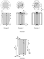
- the cylindrical section comprises a continuous flared cylinder, which has a lower outer diameter, at the end of the flared cylinder, which is greater than an upper outer diameter, at the beginning of the flared cylinder. See, for example, Inventive Example 1 of Figure 4 , and Figure 6 .
- the lower outer diameter is > 1.2 x the upper outer diameter.
- the bottom of the flared cylinder is downstream from the top of the flared cylinder.
- the cylindrical section comprises a vertical section of length h 1 , followed by a flared section of length h 2 .
- the flared section of length h 2 is followed by a vertical section of length h 3 . See, for example, Figure 6 .
- h 1 h 2 .
- h 1 + h 2 ⁇ L, or h 1 + h 2 ⁇ L, or h 1 + h 2 L.
- d 1 is ⁇ 50 cm, or ⁇ 55 cm, or ⁇ 60 cm, or ⁇ 65 cm, or ⁇ 70 cm, or ⁇ 75 cm, or ⁇ 80 cm. In one embodiment, d 1 is ⁇ 300 cm, or ⁇ 280 cm, or ⁇ 260 cm, or ⁇ 240 cm, or ⁇ 220 cm, or ⁇ 200 cm, or ⁇ 180 cm, or ⁇ 160 cm.
- the shroud of component B comprises 8 separate sections, and wherein 4 of the sections are located at a distance d 1 from the center of component A, and 4 of the sections are located at a distance d 2 from the center of component A; and wherein d 2 > d 1 .
- d 2 > 1.2 x d 1 . See, for example, Inventive Example 3 of Figure 4 .
- d 1 is ⁇ 50 cm, or ⁇ 55 cm, or ⁇ 60 cm, or ⁇ 65 cm, or ⁇ 70 cm, or ⁇ 75 cm, or ⁇ 80 cm. In one embodiment, d 1 is ⁇ 300 cm, or ⁇ 280 cm, or ⁇ 260 cm, or ⁇ 240 cm, or ⁇ 220 cm, or ⁇ 200 cm, or ⁇ 180 cm, or ⁇ 160 cm.
- the cylindrical section of component B comprises an upper continuous radial section of length L C , and a lower segmented section comprising ⁇ 2 separate segments, each of length Ls; and wherein L S > L C ; and wherein L C is measured from the top of the shroud to the end of the upper continuous radial section; and wherein L S is measured from the top of the shroud to the end of a lower segmented section.
- the lower segmented section comprising ⁇ 4 separate segments, each of length Ls; and wherein L S > L C .
- L S > 1.2 x L C See, for example, Inventive Example 4 of Figure 4 .
- L C is ⁇ 70 cm, or ⁇ 75 cm, or ⁇ 80 cm, or ⁇ 85 cm, or ⁇ 90 cm, or ⁇ 95 cm, or ⁇ 100 cm. In one embodiment, L C is ⁇ 400 cm, or ⁇ 380 cm, or ⁇ 360 cm, or ⁇ 340 cm, or ⁇ 320 cm, or ⁇ 300 cm, or ⁇ 280 cm, or ⁇ 260 cm, or ⁇ 240 cm, or ⁇ 220 cm, or ⁇ 200 cm.
- the shroud of component B has a design, such that the maximum average downward velocity of the solvent vapor at location y, in the gap of component C, meets the following equations 5A to 5C: V vd ⁇ qDy g 1 + D 2 2 ⁇ D 2 2 , if y ⁇ h 1 V vd ⁇ qDy g 1 + y ⁇ h 1 tan ⁇ + D 2 2 ⁇ D 2 2 , if h 2 ⁇ y > h 1
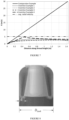
- At length h 1 as measured from the top of the heater or distributor, there begins a conical section, with an angle ⁇ from the vertical axis, as defined by the initial gap g 1 and the length h 1 at the top part of the shroud. See, for example, Inventive example 1 in Figure 4 as depicted by Design-1 in Figure 5 and Figure 6 .
- At length h 2 as measured from the bottom of length h 1 , there begins a cylindrical section as defined by the constant gap distance g, evaluated at length h 2 , and that has a length h 3 as measured from the bottom of length h 2 .
- h 1 is from greater than 0 to 200 inches, or from 2 to 100 inches, or from 4 to 80 inches, or from 6 to 60 inches.
- ⁇ is from 5 to 25 degrees, or from 10 to 15 degrees.
- V vd is from 1 to 30 m/s, or from 2 to 15 m/s.
- h 2 is from greater than 0 to 300 inches, or from 2 to 250 inches, or from 4 to 220 inches, or from 6 to 200 inches.
- h 3 is from greater than 0 to 100 inches, or from 2 to 80 inches, or from 4 to 60 inches, or from 6 to 40 inches.
- the shroud of component B has a design, such that the maximum average downward velocity of the solvent vapor at location y, in the gap of component C, meets the following equations 6A, 6B and 6C: where D is the diameter of component A, if y ⁇ ⁇ V vd ⁇ qDy g 3 + D 2 2 ⁇ D 2 2 , if ⁇ ⁇ y ⁇ L ⁇ ⁇ V vd ⁇ qDy n ⁇ 2 D + 2 g 3 y ⁇ ⁇ + g 3 + D 2 2 ⁇ D 2 2 , if L ⁇ ⁇ ⁇ y ⁇ L V vd ⁇ qDy n ⁇ 2 D + 2 g 3 y ⁇ ⁇ ⁇ + g 3 + D 2 2 ⁇ D 2 2 , if L ⁇ ⁇ ⁇ y ⁇ L V vd ⁇ qDy n ⁇ 2 D + 2 g 3 y ⁇ ⁇ ⁇ + g 3 + D 2 2
- g 3 is from 2 to 40 inches, or from 6 to 30 inches, or from 12 to 20 inches.
- ⁇ is from 10 to 45 degrees, or from 12 to 35 degrees or from 15 to 30 degrees.
- a and ⁇ each, independently, range from greater than 0 to 60 inches, or from 1 to 50 inches, or from 3 to 40 inches.
- the devolatilizer operates at a temperature (T) from 100°C to 300°C, or from 120°C to 280°C, from 140°C to 260°C, from 160°C to 240°C, from 180°C to 220°C, as measured with thermocouples imbedded in thermowells, and at a pressure (P) from 5 mBar to 100 mBar, or from 10 mBar to 80 mBar, or from 15 mBar to 60 mBar, as measured with pressure transducers imbedded into the vessel.
- T temperature
- P pressure
- the devolatilizer operates at a temperature (T) from 100°C to 300°C, or from 120°C to 280°C, from 140°C to 260°C, from 160°C to 240°C, from 180°C to 220°C, and at a pressure (P) from 5 mBar to 50 mBar, or from 10 mBar to 40 mBar, or from 15 mBar to 30 mBar.
- T temperature
- P pressure
- the devolatilizer further comprises an outer vessel, and wherein there is a gap (gj) located between the outer surface of the cylindrical section of component B and the inner surface of the outer vessel.
- the width of g 5 varies continuously or discontinuously along the length of the cylindrical section of component B.
- the ratio of "the minimum width of g 5 " to "the maximum width of the gap of component C" is ⁇ 0.5, or ⁇ 1.0, or ⁇ 1.5, or ⁇ 2.0, or ⁇ 2.5, or ⁇ 3.0.
- the diameter of the outer vessel, D tank is from 1 m to 10 m, or from 2 m to 10 m.
- the top of the shroud of component B is welded to the wall of the outer vessel.
- a reactor system comprising at least one reactor and the devolatilizer of one or more embodiments described herein.
- the reactor is a loop reactor.
- a solution polymerization process to form a polymer comprising at least the following steps:
- the polymer-rich solution comprises ⁇ 60 wt%, or ⁇ 70 wt%, or ⁇ 80 wt%, or ⁇ 90 wt%, or ⁇ 95 wt% of the polymer, based on the weight of the polymer-rich solution.
- the polymer is an olefin-based polymer, and further an ethylene-based polymer.
- the reactor is a single loop reactor or a dual loop reactor. Suitable reactors are disclosed in International Publication Number WO 97/36942 , entitled “Olefin Solution Polymerization.”
- a devolatilizer as described herein, may also be used in the isolation of a polymer product formed in a high pressure ( ⁇ 1000 bar), free-radical polymerization.
- LDPE low density polyethylene
- Such a devolatilizer is well suited as a separator for the removal of ethylene, minor solvent components and/or additives (for example, peroxide derivatives and catalyst derivatives) from a LDPE or other polymer product.
- composition includes material(s) which comprise the composition, as well as reaction products and decomposition products formed from the materials of the composition.
- polymer refers to a polymeric compound prepared by polymerizing monomers, whether of the same or a different type.
- the generic term polymer thus embraces the term homopolymer (employed to refer to polymers prepared from only one type of monomer, with the understanding that trace amounts of impurities can be incorporated into the polymer structure), and the term interpolymer as defined hereinafter. Trace amounts of impurities may be incorporated into and/or within the polymer.
- interpolymer refers to a polymer prepared by the polymerization of at least two different types of monomers.
- the generic term interpolymer thus includes copolymers (employed to refer to polymers prepared from two different types of monomers), and polymers prepared from more than two different types of monomers.
- olefin-based polymer refers to a polymer that comprises, in polymerized form, 50 wt% or a majority amount of an olefin monomer, for example ethylene or propylene (based on the weight of the polymer), and optionally may comprise at least one polymerized comonomer.
- ethylene-based polymer refers to a polymer that comprises 50 wt% or a majority amount of polymerized ethylene monomer (based on the total weight of the polymer), and optionally may comprise at least one polymerized comonomer.
- ethylene/ ⁇ -olefin interpolymer refers to an interpolymer that comprises, in polymerized form, 50 wt% or a majority amount of ethylene monomer (based on the weight of the interpolymer), and at least one ⁇ -olefin.
- ethylene/ ⁇ -olefin copolymer refers to a copolymer that comprises, in polymerized form, 50 wt% or a majority amount of ethylene monomer (based on the weight of the copolymer), and an ⁇ -olefin, as the only two monomer types.
- propylene-based polymer refers to a polymer that comprises, in polymerized form, a majority amount of propylene monomer (based on the total weight of the polymer) and optionally may comprise at least one polymerized comonomer.
- devolatilizer or “devo,” or “devolatilization tank,” as used herein, refer to a vessel, typically cylindrical in shape at the top, and with a conical section at the bottom; and which can operate at above atmospheric pressure or under a vacuum; and which typically has at least one inlet for the polymeric solution, and one or more outlet(s) for vapor to exit, typically located at the top, and an outlet for polymer melt at the bottom.
- the purpose of a devolatilizer (devo) vessel is to remove solvent from a polymerization product.
- a process can have multiple devolatilizer (devo) vessels operating at different conditions, in order to remove residual solvent from the polymer product.
- solvent refers to an organic compound or a mixture of two or more organic compounds.
- a typical solvent includes ISOPAR ® E (from ExxonMobil), which is produced from petroleum-based raw materials that are treated with hydrogen in the presence of a catalyst to produce a low odor, low aromatic hydrocarbon solvent.
- the major components include alkanes, isoalkanes, and cycloalkanes.
- the solvent dissolves the polymer and reaction components of interest.
- polymer solution refers to a single-phase solution of a polymer dissolved in a solvent, such as ISOPAR ® E.
- a polymer solution typically contains from 20 to 95% by weight polymer.
- solution polymerization refers to polymerization process, in which the polymer product is dissolved in the solvent of the polymerization process.
- distributed refers to an apparatus designed to distribute a polymeric solution, so as to increase the area of the polymer solution for mass transfer and removal and disengagement of the polymer melt from the vapor solvent compounds.
- shroud refers to a metal piece of various designs that surrounds a distributor, a heater, or a heater/distributor combination, leaving a gap between the outer surface of the distributor, the heater, or the heater/distributor combination, and its inner surface.
- Component B the shroud - is used to help prevent the splashing of solvent and/or polymer into the or onto the inner surface of a vessel which contains component A and component B.
- Segmented sections of component B are pieces of metal that surround component A, and are placed, in such a way, that they partially surround component A, with spaces open for vapor and polymer to escape the region between the outer surface of component A and the inner surface of the component B.
- gap refers to the region defined by the outer surface of component A, the heater/distributor combination) and the inner surface of the component B (shroud).
- outer surface of component A refers to the outer most surface of component A.
- diameter of component A refers to the outer diameter of component A.
- length of component A refers to the longest vertical section of component A.
- diameter of component B refers to the outer most diameter of component B.
- length of component B refers to the longest section of component B.
- Polymer-rich solution a polymer solution, typically an ethylene-based polymer in a hydrocarbon solvent, such that the polymer concentration is greater than 50% by weight in that solution.
- Solvent vapor typically compounds found in the solvent, such as, for example, alkanes, that are vaporized under the process conditions.
- the total solvent vapor flow rate in regard to the determination of the average vertical downward velocity, can be calculated from the polymer production rate and the percentage of solvent present at the inlet of the devo.
- the cross-sectional area available for flow in regard to the determination of the average vertical downward velocity, can be calculated from the geometries of the gap formed by the outer surface of component A and the inner surface of component B along the length, L, as measured from the top of component B.
- the length (L) of the at least one cylindrical section, situated outside the periphery of component A, refers to the longest distance from the top to the bottom of this cylindrical section.
- the bottom of the cylindrical section is downstream from the top of the cylindrical section.
- length of a weld line refers to the shorter dimension (typically a vertical dimension) of the weld line.
- the length of the weld line can be from 1 mm to 50 mm, or from 2 mm to 20 mm.
- reactor system refers to the one or more apparatus used to polymerize a polymer, and the one or more apparatus used to isolate a polymer product.
- compositions claimed, herein, through use of the term “comprising” may include any additional additive, adjuvant, or compound, whether polymeric or otherwise, unless stated to the contrary.
- the term, “consisting essentially of” excludes from the scope of any succeeding recitation any other component, step or procedure, excepting those that are not essential to operability.
- the term “consisting of” excludes any component, step or procedure not specifically delineated or listed.
- Samples for density measurement were prepared according to ASTM D4703. Measurements were made, according to ASTM D792, Method B, within one hour of sample pressing.
- a GPC-IR high temperature chromatographic system from PolymerChar (Valencia, Spain), was equipped with a Precision Detectors (Amherst, MA), 2-angle laser light scattering detector Model 2040, an IR5 infra-red detector and a 4-capillary viscometer, both from PolymerChar. Data collection was performed using PolymerChar Instrument Control software and data collection interface. The system was equipped with an on-line, solvent degas device and pumping system from Agilent Technologies (Santa Clara, CA).
- Injection temperature was controlled at 150 degrees Celsius.
- the columns used were three, 10-micron "Mixed-B” columns from Polymer Laboratories (Shropshire, UK).
- the solvent used was 1,2,4-trichlorobenzene.
- the samples were prepared at a concentration of "0.1 grams of polymer in 50 milliliters of solvent.”
- the chromatographic solvent and the sample preparation solvent each contained "200 ppm of butylated hydroxytoluene (BHT)." Both solvent sources were nitrogen sparged. Ethylene-based polymer samples were stirred gently at 160 degrees Celsius for three hours.
- the injection volume was "200 microliters,' and the flow rate was “1 milliliters/minute.”
- the GPC column set was calibrated by running 21 "narrow molecular weight distribution” polystyrene standards.
- the molecular weight (MW) of the standards ranges from 580 to 8,400,000 g/mole, and the standards were contained in six "cocktail” mixtures. Each standard mixture had at least a decade of separation between individual molecular weights.
- the standard mixtures were purchased from Polymer Laboratories.
- the polystyrene standards were prepared at "0.025 g in 50 mL of solvent" for molecular weights equal to, or greater than, 1,000,000 g/mole, and at "0.050 g in 50 mL of solvent” for molecular weights less than 1,000,000 g/mole.
- the polystyrene standards were dissolved at 80°C, with gentle agitation, for 30 minutes. The narrow standards mixtures were run first, and in order of decreasing "highest molecular weight component," to minimize degradation.
- Mn(conv gpc) Number-average molecular weight (Mn(conv gpc)), weight average molecular weight (Mw-conv gpc), and z-average molecular weight (Mz(conv gpc)) were calculated according to Equations 2-4 below.
- Equation 2-4 the RV is column retention volume (linearly-spaced), collected at "1 point per second," the IR is the baseline-subtracted IR detector signal, in Volts, from the IR5 measurement channel of the GPC instrument, and M PE is the polyethylene-equivalent MW determined from Equation 1. Data calculation were performed using "GPC One software (version 2.013H)" from PolymerChar.
- Figure 1 describes an overall solution polymerization process for polymerizing one or more alpha-olefin monomers, in a sufficient amount of solvent, to produce an olefin-based polymer.
- Basic polymerization and isolation apparatuses include feed lines (for example, ethylene feed, hydrogen feed, catalyst system feed(s), a comonomer feed (for example, an alkene, such as butene, hexene or octene), a reactor system, a devolatilizer system, a solvent recovery system, a purification system, a pelletization system, and a system for pellet drying and material handling.
- feed lines for example, ethylene feed, hydrogen feed, catalyst system feed(s), a comonomer feed (for example, an alkene, such as butene, hexene or octene)
- a reactor system for example, ethylene feed, hydrogen feed, catalyst system feed(s), a comonomer feed (for example, an alkene, such as but
- the polymer solution, exiting the reactor system has a polymer content from 3 to 40 percent by weight, preferably 10 to 30 percent by weight, based on the weight of the solution.
- Such polymerizations can be used to produce polymers, for example, substantially linear polymers, having an average molecular weight from 2,000 to 1,000,000 g/mole.
- the reacting system can comprise adiabatic reactors, isothermal reactors, or combinations thereof.
- the reactor temperatures can range from 100 to 300°C, further from 100 to 250°C, and preferably from 150 to 220°C, and the pressures can range from 350 to 3,000 psi, preferably from 700 to 1,000 psi.
- the polymeric solution is concentrated by means of adiabatic flashes, with intermediate heating of the solution, to result in a polymer melt with sufficiently low residual solvent to allow for pelletization, drying and packaging of the pellets.
- the solvent is recovered, purified, and recycled back to the reactor system, where it is injected with fresh monomers.
- This process can be used for making olefin-based polymers, such as ethylene homopolymers, or interpolymers with other alkenes (for example, copolymers or terpolymers), and, optionally, a diene (for example an EPDM terpolymer).
- Catalysts used can be Ziegler-Natta, bis-metallocene, constrained geometry, or a polyvalent aryloxyether complex.
- a variety of commercial solvents could be used, such as ISOPAR ® E from ExxonMobil. In practice, the solvent exiting the reactor system comprises unreacted monomers as well as isomers of those monomers and various impurities.
- FIG. 2 A schematic of a suitable devolatilization process is presented in Figure 2 .
- the polymer solution exiting the reactor system enters a first flash unit, and is subject to a devolatization step.
- the polymer concentration is increased to 40 to 90 wt%, preferably to 60 to 85 wt%, based on the weight of the concentrated polymer solution.
- the liquid stream from the first flash unit can be heated up to 300°C, preferably up to 260°C, and it is flashed under vacuum to remove more solvent, to less than 3,000 ppm by weight, preferably less than 500 ppm by weight.
- the heater can be situated outside the second flash unit, and a distributor can be situated inside the second flash unit, or the heater can be situated inside the second flash unit, and thus the heater operates as both a heater of the concentrated polymer solution and a distributor for the resulting polymer melt.
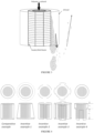
- FIG 3 and Figure 4 are schematics of flash units, each containing a heater and/or distributor.
- the flash unit is a vessel, and it can be cylindrical in shape at the top with a converging conical section at the bottom.
- the diameter of the cylindrical section can be two to six times the diameter of the heater and/or distributor.
- the length of the cylindrical section can be one to two times the length of the heater and/or distributor.
- the conical section can be two to five times the length of the cylindrical portion of the vessel and it ends at an opening of a gear pump or extruder.
- the vessel can operate at above atmospheric pressure or under vacuum. There is an inlet for the polymeric solution, and one or multiple outlets for vapor to exit, typically located at the top, and an outlet for the polymer melt at the bottom.
- the purpose of the vessel is to remove solvent from the polymerization product.
- a process can have multiple flash vessels operating at different conditions in order to remove residual solvent from the polymer product gradually. Examples of suitable heaters are described in U.S. Patent 5,453,158 and U.S. Patent 8,518,212 .
- the concentrated polymer (polymer-rich) solution flows into a hollow core inside the "heater and distributor,” and exits by moving radially outwards through a multiplicity of slots, extending horizontally, from the core to the outer wall of the "heater and/or distributor.”
- solvent can be vaporized, when the pressure becomes low enough to reach the bubble point of the polymer solution, creating two-phase flow.
- the vapor solvent separates from the polymer, as the two-phase solution exits the heater or distributor slots.
- Inventive examples 2 and 4 in Figure 4 are variations of Design-2 in Figure 5 .
- the shroud is mostly cylindrical with constant gap g 3 , where g 3 can range from 2 to 40 inches, preferably 12 to 20 inches.
- the segment of each opening is such that it forms an angle A, when observed from the cross view at the top of the design, and ⁇ can range from 10 to 45 degrees, preferably from 15 to 30 degrees.
- Inventive example 3, in Figure 4 is described by Design 3 in Figure 5 , and it is a variation of inventive example 2: there is an additional layer of segmented shroud, which is larger in diameter than the segmented shroud in inventive examples 2 and 4.
- the gap g 4 between the outer diameter of the innermost partial shroud and the inner diameter of the outer segmented shroud ranges from 2 to 30 inches.
- the outer shroud creates segments, such that each segment of the outer shroud is placed to cover the opening from the inner-most partial cylindrical shroud, with each size defined by a segment forming an angle ⁇ when observed from the top cross-section of the design, where ⁇ can range from 10 to 60 degrees, preferably from 15 to 40 degrees.
- the shroud designs in inventive examples 2 to 4 are such so that they satisfy equations 6A to 6C, depending on a location y, as measured from the top of the heater and/or distributor: if y ⁇ ⁇ V vd ⁇ qDy g 3 + D 2 2 ⁇ D 2 2 , if ⁇ ⁇ y ⁇ L ⁇ ⁇ V vd ⁇ qDy n ⁇ 2 D + 2 g 3 y ⁇ ⁇ + g 3 + D 2 2 ⁇ D 2 2 , ifL ⁇ ⁇ ⁇ y ⁇ L V vd ⁇ qDy n ⁇ 2 D + 2 g 3 y ⁇ ⁇ ⁇ + g 3 + D 2 2 ⁇ D 2 2 ,
- the melt polymer density is taken to be 742 kg/m 3 and the vapor density is taken to be 0.085 kg/m 3 .
- the polymer melt density can be measured using method ASTM D1238. This method typically provides a melt density for polyethylene materials at 190°C of 0.7634 g/cm 3 .
- the solvent vapor density can be estimated using an equation of state at the process conditions, such as PC-SAFT implemented in the AspenTech software program[4], given the vapor stream temperature and pressure. In these examples, the vapor density was estimated at 210°C and 30 mbar absolute pressure.
- V vd has been chosen to be 5 m/s.
- the same heater and/or distributor unit (component A) was used in each devo design below. Additionally, the gap width w mentioned earlier would be referred to as either g 1 and g 2 for Inventive Example 1 ( Fig. 6 ) and g 3 for Inventive Examples 2, 3, and 4.
- the number of openings in component A multiplied by the cross-sectional area of each opening 0.753 m 2 .
- the total solvent vapor flow rate at the exit of component A, at the temperature and the pressure of the devolatilizer, is based upon the total polymer production rate.
- Polymer production rate 7000 kg/hr;
- the temperature and pressure represent equilibrated temperatures and pressures.
- Volumetric flow rate of solvent 3.92 m 3 /sec.
- Volumetric flow rate of isolated polymer 0.0027 m 3 /sec.
- Density of solvent (kg/m 3 ): generate calibration curve - measure solvent density versus temperature and set pressure, for example ASTM D 1657; determine density at temperature of interest.
- Component A has a diameter ⁇ 0.76 m, at each distance along the length of component A.
- the outer vessel has a diameter, D tank , of ⁇ 1.8 m.
- total downward solvent vapor at distance y has the following velocities; a) within the gap, an average vertical downward velocity, defined as the ratio of "the total solvent vapor flow rate, " to "the cross-sectional area available for flow,” and wherein each of "the total solvent vapor flow rate” and “the cross sectional area available for flow” is measured at the same vertical distance, y, from the top of the outer surface of component A.
- the average vertical downward velocity the total solvent vapor flow rate,” to "the cross-sectional area available for flow.
- Component A has a diameter ⁇ 0.76 m at each distance along the length of component A.
- the outer vessel has a diameter, D tank , of ⁇ 1.0 m.
- an average vertical downward velocity defined as the ratio of "the total solvent vapor flow rate,” to “the cross-sectional area available for flow,” and wherein each of “the total solvent vapor flow rate” and “the cross sectional area available for flow” is measured at the same vertical distance, y, from the top of the outer surface of component A.
- q (volumetric flow rate of solvent)/ (unit surface area of component A).
- D outer diameter of component A.
- D 0.762 m.
- L length of component A.
- Area 3.95 m 2 .
- Volumetric flow rate of solvent 3.92 m 3 /sec.
- Component A has a diameter ⁇ 0.76 m at each distance along the length of component A.
- the outer vessel has a diameter, D tank , of ⁇ 1.5 m.
- an average vertical downward velocity defined as the ratio of "the total solvent vapor flow rate,” to “the cross-sectional area available for flow,” and wherein each of “the total solvent vapor flow rate” and “the cross sectional area available for flow” is measured at the same vertical distance, y, from the top of the outer surface of component A.
- total solvent vapor flow rate downward from at a given vertical distance, y, from the top of the outer surface of component A has the following velocities; a) within the gap, an average vertical downward velocity, defined as the ratio of "the total solvent vapor flow rate, " to "the cross-sectional area available for flow,” and wherein each of "the total solvent vapor flow rate” and “the cross sectional area available for flow” is measured at the same vertical distance, y, from the top of the outer surface of component A.
- Component A has a diameter ⁇ 0.76 m at each distance along the length of component A.
- the outer vessel has a diameter, D tank , of ⁇ 1.2 m.
- total solvent vapor flow rate downward from at a given vertical distance, y, from the top of the outer surface of component A has the following velocities; a) within the gap, an average vertical downward velocity, defined as the ratio of "the total solvent vapor flow rate, " to "the cross-sectional area available for flow,” and wherein each of "the total solvent vapor flow rate” and “the cross sectional area available for flow” is measured at the same vertical distance, y, from the top of the outer surface of component A.
- Component A has a diameter ⁇ 0.76 m, at each distance along the length of component A.
- the outer vessel has a diameter, D tank , of ⁇ 1.0 m.
- total solvent vapor flow rate downward from at a given vertical distance, y, from the top of the outer surface of component A has the following velocities; a) within the gap, an average vertical downward velocity, defined as the ratio of "the total solvent vapor flow rate,” to "the cross-sectional area available for flow,” and wherein each of "the total solvent vapor flow rate” and “the cross sectional area available for flow” is measured at the same vertical distance, y, from the top of the outer surface of component A.
- the average vertical downward velocity ⁇ the radial average velocity exiting the component A. 14.8 m/sec > 5.2 m/sec, for y 0.80 m.
Landscapes
- Chemical & Material Sciences (AREA)
- Chemical Kinetics & Catalysis (AREA)
- Health & Medical Sciences (AREA)
- Medicinal Chemistry (AREA)
- Polymers & Plastics (AREA)
- Organic Chemistry (AREA)
- Dispersion Chemistry (AREA)
- Addition Polymer Or Copolymer, Post-Treatments, Or Chemical Modifications (AREA)
- Polymerisation Methods In General (AREA)
- Processes Of Treating Macromolecular Substances (AREA)
- Vaporization, Distillation, Condensation, Sublimation, And Cold Traps (AREA)
Claims (14)
- Entgaser (Devo), der bei einer Temperatur (T) und einem Druck (P) arbeitet, für die Separierung von mindestens einem Anteil eines Lösungsmittels aus einer polymerreichen Lösung, umfassend das Lösungsmittel und ein Polymer, und wobei der Entgaser mindestens die folgenden Komponenten umfasst:A) eine Heizelement-/Verteilerkombination (Komponente A) einer Länge L, die vertikale Distanz von der Oberseite zu der Unterseite der Komponente A;B) eine Ummantelung (Komponente B), die sich um einen Teil oder die gesamte Peripherie der Komponente A befindet; und wobei die Ummantelung mindestens eine zylindrische Sektion umfasst, die außerhalb des Umfangs der Komponente A liegt, und wobei diese zylindrische Sektion mindestens einen Anteil des Umfangs der Komponente A umschließt, undC) ein Spalt (Komponente C), der sich zwischen der Außenoberfläche der Komponente A und der Innenoberfläche der Komponente B befindet, und wobei der Spalt eine Breite (w) aufweist, die Distanz von der Außenoberfläche der Komponente A zu der Innenoberfläche der mindestens einen zylindrischen Sektion der Komponente B, und der Spalt eine Länge ≤ L aufweist; und wobei w entlang der Länge L kontinuierlich oder diskontinuierlich abwärts erweitert ist; wobei Komponente A einen Innenkanal und eine Vielzahl von Querschnittsöffnungen umfasst, die sich von dem Innenkanal zu dem Spalt erstreckt; der Entgaser konfiguriert ist, um in dem Innenkanal eine polymerreiche Lösung aufzunehmen, die sich durch die Querschnittsöffnungen hindurch radial bewegt, und innerhalb jeder Öffnung ein Teil oder das gesamte Lösungsmittel der polymerreichen Lösung verdampft wird, wodurch ein Lösungsmitteldampf und eine Polymerschmelze ausgebildet werden; und wobei die Polymerschmelze in den Spalt eintritt und von dem Eintrittspunkt in den Spalt abwärts strömt, und wobei ein Teil oder der gesamte Lösungsmitteldampf von dem Eintrittspunkt in den Spalt abwärts strömt;wobei für jede vertikale Distanz, y, wie von der Oberseite der Außenoberfläche der Komponente A gemessen, die Gesamtmenge des Lösungsmitteldampfs, der Komponente A in der gegebenen Distanz y verlässt, und abwärts in die Komponente C strömt, die folgenden Geschwindigkeiten aufweist:a) innerhalb des Spalts eine durchschnittliche vertikale Abwärtsgeschwindigkeit, definiert als das Verhältnis "der Gesamtlösungsmitteldampfströmungsrate" zu "der für die Strömung verfügbaren Querschnittsfläche", und wobei jedes der "Gesamtlösungsmitteldampfströmungsrate" und der "für die Strömung verfügbaren Querschnittsfläche" in der gleichen vertikalen Distanz, y, gemessen werden, undb) eine radiale durchschnittliche Geschwindigkeit, die aus Komponente A austritt, definiert als das Verhältnis "der Gesamtlösungsmitteldampfströmungsrate an dem Austritt von Komponente A bei der Temperatur (T) und dem Druck (P) des Entgasers" zu "Anzahl der Öffnungen in Komponente A multipliziert mit der Querschnittsfläche jeder Öffnung;"wobei die durchschnittliche vertikale Abwärtsgeschwindigkeit ≤ der radialen durchschnittliche Geschwindigkeit ist, die aus Komponente A austritt.
- Entgaser nach Anspruch 1, wobei, für jede Distanz y, wie von der Oberseite der Außenoberfläche der Komponente A gemessen, die durchschnittliche vertikale Abwärtsgeschwindigkeit des Lösungsmittels in einem Bereich von 1,0 m/s bis 10,0 m/s liegt.
- Entgaser nach einem der vorstehenden Ansprüche, wobei, für die Komponente B, die zylindrische Sektion einen zylindrischen, aufgeweiteten Zylinder umfasst, der, an dem Ende des aufgeweiteten Zylinders, einen Durchmesser aufweist, der größer als der Durchmesser an dem Anfang des aufgeweiteten Zylinders ist.
- Entgaser nach Anspruch 3, wobei der Durchmesser an dem Ende der aufgeweiteten Sektion größer als das 1,2-fache des Durchmessers an dem Anfang der aufgeweiteten Sektion ist.
- Entgaser nach Anspruch 3, wobei die Ummantelung der Komponente B ≥ 4 separate Sektionen umfasst und sich jede Sektion in einer Distanz d1 von der Mitte der Komponente A befindet.
- Entgaser nach Anspruch 5, wobei die Ummantelung der Komponente B mindestens 8 separate Sektionen umfasst und wobei sich mindestens 4 der Sektionen in einer Distanz d1 von der Mitte der Komponente A befinden, und sich mindestens 4 der Sektionen in einer Distanz d2 von der Mitte der Komponente A befinden; und wobei d2 > d1.
- Entgaser nach Anspruch 6, wobei d2 > 1,2 x d1.
- Entgaser nach einem der Ansprüche 1 bis 6, wobei die zylindrische Sektion der Komponente B eine obere durchgehende radiale Sektion der Länge Lc, und eine untere segmentierte Sektion umfasst, umfassend ≥ 2 separate Segmente, jedes mit einer Länge L S ; und wobei LS > LC ; und wobei LC von der Oberseite der Komponente B bis zu dem Ende der oberen durchgehenden radialen Sektion gemessen wird; und wobei LS von der Oberseite der Komponente B bis zu dem Ende einer unteren segmentierten Sektion gemessen wird; und wobei die untere segmentierte Sektion ≥ 4 separate Segmente umfasst, jedes mit einer Länge Ls; und wobei Ls > Lc.
- Entgaser nach einem der vorstehenden Ansprüche, wobei der Entgaser bei einer Temperatur (T) von 100 °C bis 300 °C und bei einem Druck (P) von 3 mBar bis 100 mBar arbeitet.
- Entgaser nach einem der vorstehenden Ansprüche, wobei der Entgaser ferner ein Außengefäß umfasst und wobei ein Spalt (g5) vorhanden ist, der sich zwischen der Außenoberfläche der zylindrischen Sektion der Komponente B und der Innenoberfläche des Außengefäßes befindet;
und wobei die Breite von g5 entlang der zylindrischen Sektion der Komponente B kontinuierlich oder diskontinuierlich variiert; und wobei das Verhältnis der "Mindestbreite von g5 " zu "der Maximalbreite des Spalts der Komponente C" ≥ 0,5 ist. - Reaktorsystem, umfassend mindestens einen Reaktor und den Entgaser nach einem der vorstehenden Ansprüche.
- Reaktorsystem nach Anspruch 11, wobei der mindestens eine Reaktor ein Schlaufenreaktor ist.
- Lösungspolymerisierungsverfahren, um ein Polymer auszubilden, das Verfahren umfassend mindestens die folgenden Schritte:i) Reagieren einer Mischung, umfassend ein Lösungsmittel, ein Monomer und optional ein oder mehrere Comonomere, in mindestens einem Reaktor, um eine Polymerlösung auszubilden, umfassend das Lösungsmittel und das Polymer;ii) Separieren von mindestens einem Anteil des Lösungsmittels von der Polymerlösung, um eine polymerreiche Lösung auszubilden, umfassend das Polymer und das Lösungsmittel, und wobei die polymerreiche Lösung mehr Polymer als die Polymerlösung umfasst;iii) Separieren von mindestens einem Anteil des Lösungsmittels von der polymerreichen Lösung unter Verwendung des Entgasers nach einem der Ansprüche 1 bis 10.
- Verfahren nach Anspruch 13, wobei das Polymer ein Polymer auf Olefinbasis ist.
Applications Claiming Priority (2)
| Application Number | Priority Date | Filing Date | Title |
|---|---|---|---|
| US201862678656P | 2018-05-31 | 2018-05-31 | |
| PCT/US2019/034788 WO2019232290A1 (en) | 2018-05-31 | 2019-05-31 | Devolatilizer design |
Publications (2)
| Publication Number | Publication Date |
|---|---|
| EP3801802A1 EP3801802A1 (de) | 2021-04-14 |
| EP3801802B1 true EP3801802B1 (de) | 2024-11-27 |
Family
ID=66913044
Family Applications (1)
| Application Number | Title | Priority Date | Filing Date |
|---|---|---|---|
| EP19731512.0A Active EP3801802B1 (de) | 2018-05-31 | 2019-05-31 | Verdampferentwurf |
Country Status (8)
| Country | Link |
|---|---|
| US (1) | US12098233B2 (de) |
| EP (1) | EP3801802B1 (de) |
| JP (1) | JP7404273B2 (de) |
| KR (1) | KR20210014120A (de) |
| CN (1) | CN112334203B (de) |
| ES (1) | ES3008277T3 (de) |
| SG (1) | SG11202011399TA (de) |
| WO (1) | WO2019232290A1 (de) |
Families Citing this family (1)
| Publication number | Priority date | Publication date | Assignee | Title |
|---|---|---|---|---|
| SG11202011412UA (en) | 2018-05-31 | 2020-12-30 | Dow Global Technologies Llc | Method and system for polymer production |
Citations (2)
| Publication number | Priority date | Publication date | Assignee | Title |
|---|---|---|---|---|
| GB982598A (en) * | 1962-07-04 | 1965-02-10 | Auto Bath Company Ltd | Improvements in or relating to spray nozzles |
| US3366458A (en) * | 1963-06-03 | 1968-01-30 | Jori Luciano | Apparatus for diluting an acetic acid solution of cellulose acetate with water |
Family Cites Families (85)
| Publication number | Priority date | Publication date | Assignee | Title |
|---|---|---|---|---|
| US2969347A (en) * | 1961-01-24 | Recovery of olefin polymers from solution | ||
| US2411186A (en) | 1941-11-27 | 1946-11-19 | Hydrojet Corp | Process for releasing gases from liquids |
| US3014702A (en) | 1958-12-01 | 1961-12-26 | Dow Chemical Co | Heat exchanger |
| NL279953A (de) | 1961-06-26 | |||
| NL6504939A (de) * | 1965-04-20 | 1966-10-21 | ||
| FR1472994A (fr) * | 1965-10-06 | 1967-03-17 | Commissariat Energie Atomique | Procédé et dispositif de reconcentration de solutions salines |
| US3738409A (en) | 1971-01-27 | 1973-06-12 | Welding Engineers | Apparatus for flash-concentrating viscous liquids |
| FR2308052A1 (fr) | 1975-04-18 | 1976-11-12 | Commissariat Energie Atomique | Echangeur de chaleur a tubes plongeurs |
| DE2606612A1 (de) | 1976-02-19 | 1977-08-25 | Basf Ag | Verfahren und vorrichtung zur entfernung von verdampfbaren anteilen aus hochviskosen loesungen oder schmelzen thermoplastischer kunststoffe |
| AT360442B (de) * | 1979-02-20 | 1980-01-12 | Waagner Biro Ag | Verfahren und einrichtung zur verdampfung von fluessigkeiten |
| US4431050A (en) | 1981-10-16 | 1984-02-14 | Avco Corporation | Stacked-plate heat exchanger made of identical corrugated plates |
| JPS58180255A (ja) * | 1982-04-16 | 1983-10-21 | Matsushita Electric Ind Co Ltd | 噴霧装置 |
| US4808007A (en) | 1982-05-13 | 1989-02-28 | Komax Systems, Inc. | Dual viscosity mixer |
| US4423767A (en) | 1983-02-11 | 1984-01-03 | The Dow Chemical Company | Flat plate heat exchange apparatus |
| US4564063A (en) | 1984-04-16 | 1986-01-14 | The Dow Chemical Company | Annular heat exchanger |
| US4616937A (en) | 1985-04-16 | 1986-10-14 | Komax Systems, Inc. | Intermittent mixing apparatus |
| CA1265289A (en) | 1985-12-16 | 1990-01-30 | Viney Pal Aneja | Method and apparatus for devolatilizing polymer solutions |
| FI76699C (fi) | 1986-06-25 | 1988-12-12 | Ahlstroem Oy | Indunstare av roertyp. |
| US4753535A (en) | 1987-03-16 | 1988-06-28 | Komax Systems, Inc. | Motionless mixer |
| JPH07119259B2 (ja) | 1987-12-15 | 1995-12-20 | ポリマー テクノロジー インコーポレーテド | アクリル酸エステルの連続溶液重合方法 |
| GB8815855D0 (en) * | 1988-07-04 | 1988-08-10 | Netzsch Mastermix Ltd | Solvent recovery |
| IT1226303B (it) | 1988-07-26 | 1990-12-27 | Montedipe Spa | Processo ed apparato per la devolatilizzazione di soluzioni di polimeri. |
| JPH02232205A (ja) | 1989-03-06 | 1990-09-14 | Nippon Steel Chem Co Ltd | 揮発性物質の除去方法及びその装置 |
| AU638875B2 (en) | 1990-11-27 | 1993-07-08 | Koch (Cyprus) Limited | Tower packing with louvers |
| GB2273980B (en) | 1993-01-04 | 1997-01-29 | Falmer Investment Ltd | Dyeliquor heating arrangement |
| US5453158A (en) | 1994-03-10 | 1995-09-26 | The Dow Chemical Company | Polymer devolatilizer |
| DE19510847C2 (de) | 1995-03-17 | 2002-11-21 | Michael Rehberg | Plattenwärmetauscher |
| DE29510720U1 (de) * | 1995-07-01 | 1995-09-07 | BDAG Balcke-Dürr AG, 40882 Ratingen | Wärmetauscher |
| US5977251A (en) | 1996-04-01 | 1999-11-02 | The Dow Chemical Company | Non-adiabatic olefin solution polymerization |
| HUP9901742A3 (en) | 1996-04-01 | 2000-04-28 | Dow Global Technologies Inc Mi | Process for solution polymerization of olefin |
| US5874525A (en) * | 1997-01-24 | 1999-02-23 | Nova Chemicals Inc. | Devolatilizer tray array |
| US6114501A (en) | 1997-12-19 | 2000-09-05 | Phillips Petroleum Company | Diluent recycle process |
| ATE264345T1 (de) | 1997-12-23 | 2004-04-15 | Dow Chemical Co | Nachbehandlung zur erhöhung des polymergehaltes in einem verfahren zur lösungspolymerisation von olefinen |
| DE19817678A1 (de) | 1998-04-21 | 1999-10-28 | Bayer Ag | Vorrichtung und Verfahren zur Entfernung von flüchtigen Komponenten aus Polymerlösungen |
| AU755016B2 (en) * | 1998-05-18 | 2002-11-28 | Chevron Phillips Chemical Company Lp | Continuous slurry polymerization volatile removal |
| CA2247703C (en) | 1998-09-22 | 2007-04-17 | Nova Chemicals Ltd. | Dual reactor ethylene polymerization process |
| WO2001021303A1 (en) * | 1999-09-20 | 2001-03-29 | The Dow Chemical Company | An improved method and apparatus for devolatilization |
| EP1301258A2 (de) | 2000-05-31 | 2003-04-16 | KRATON Polymers Research B.V. | Vorrichtung und verfahren zur herstellung von polymerkrümeln |
| KR100769774B1 (ko) | 2000-10-25 | 2007-10-23 | 엑손모빌 케미칼 패턴츠 인코포레이티드 | 연속 용액중합 방법 및 장치 |
| US6764030B2 (en) | 2001-01-12 | 2004-07-20 | Diamond Power International, Inc. | Sootblower nozzle assembly with an improved downstream nozzle |
| ATE423795T1 (de) | 2002-06-24 | 2009-03-15 | Basell Poliolefine Srl | Methode zur abtrennung flüchtiger komponenten aus polymer-zusammensetzungen |
| DE10248571A1 (de) * | 2002-10-17 | 2004-04-29 | Bayer Ag | Verfahren zur Abtrennung von flüchtigen Bestandteilen von Polymeren |
| US20040176561A1 (en) | 2002-12-31 | 2004-09-09 | Gelest, Inc. | Continuous cationic polymerization of siloxanes |
| FR2855766A1 (fr) | 2003-06-06 | 2004-12-10 | Third Millenium Water Company | Procedes et appareils de distillation notamment pour produire de l'eau douce |
| DE10333577A1 (de) | 2003-07-24 | 2005-02-24 | Bayer Technology Services Gmbh | Verfahren und Vorrichtung zur Entfernung von flüchtigen Substanzen aus hochviskosen Medien |
| US7332058B2 (en) | 2003-07-31 | 2008-02-19 | Fina Technology, Inc. | Heat exchanger and process for devolatilizing polymers using same |
| US7575046B2 (en) | 2003-09-18 | 2009-08-18 | Rochester Institute Of Technology | Methods for stabilizing flow in channels and systems thereof |
| DE102004004999B4 (de) * | 2004-01-30 | 2007-03-08 | Alstom Power Energy Recovery Gmbh | Vorrichtung für den Eintritt von Heißgas in ein Heizflächenrohr eines Abhitzkessels |
| CN100334416C (zh) * | 2004-02-10 | 2007-08-29 | 华南理工大学 | 急扩加速流缩放管束空心环管壳式换热器 |
| JP2008540752A (ja) | 2005-05-11 | 2008-11-20 | バーゼル・ポリオレフィン・イタリア・ソチエタ・ア・レスポンサビリタ・リミタータ | ポリオレフィンブレンドを製造するための重合方法 |
| GB0509746D0 (en) | 2005-05-13 | 2005-06-22 | Ashe Morris Ltd | Variable plate heat exchangers |
| ES2322728B1 (es) | 2005-11-22 | 2010-04-23 | Dayco Ensa, S.L. | Intercambiador de calor de tres pasos para un sistema "egr". |
| JP5203213B2 (ja) | 2005-11-28 | 2013-06-05 | ガラ・インダストリーズ・インコーポレイテッド | 造粒処理を制御する装置及び方法 |
| FR2896576B1 (fr) | 2006-01-20 | 2008-04-18 | Alfa Laval Packinox Soc Par Ac | Installation d'echange thermique a faisceaux de plaques |
| US7883567B2 (en) | 2006-02-15 | 2011-02-08 | National University Corporation Okayama University | Deaerating and dissolving apparatus, and deaerating and dissolving method |
| JP4898279B2 (ja) | 2006-05-09 | 2012-03-14 | 株式会社ジオパワーシステム | マイナスイオン生成機能を備えた地熱利用型空調システム及び方法 |
| EP2072540A1 (de) | 2007-12-20 | 2009-06-24 | Basell Poliolefine Italia S.r.l. | Lösungspolymerisierungsverfahren zur Zubereitung von Polyolefinen |
| US8067512B2 (en) | 2008-04-10 | 2011-11-29 | Exxonmobil Research And Engineering Company | Monomer/solvent separation and recycle process for propylene containing polymers |
| DE102008044711A1 (de) | 2008-08-28 | 2010-03-04 | Emitec Gesellschaft Für Emissionstechnologie Mbh | Kombination aus Wärmetauscher und Katalysator als Komponente eines Abgassystems |
| CN201368688Y (zh) * | 2009-01-13 | 2009-12-23 | 天津商业大学 | 高性能的满液式蒸发换热器 |
| US8518212B2 (en) | 2009-02-06 | 2013-08-27 | Dow Globarl Technologies LLC | Devolatilization apparatus and process |
| EP2738182A1 (de) | 2009-07-16 | 2014-06-04 | Dow Global Technologies LLC | Polymerisationsverfahren für polymere auf olefinbasis |
| CN201477501U (zh) | 2009-08-26 | 2010-05-19 | 冯林 | 一种内存紧固装置、计算机主板和计算机 |
| CN101979116B (zh) | 2010-09-27 | 2012-02-22 | 浙江大学 | 带微凸台阵列结构的微层叠平板式液体燃料蒸发器 |
| US8697808B2 (en) | 2010-11-08 | 2014-04-15 | Equistar Chemicals, Lp | Process for making ethylene polymer blends with controlled long-chain branching |
| CN202267394U (zh) | 2011-09-26 | 2012-06-06 | 同济大学 | 用于烟气余热回收的一次表面换热器 |
| ES2625425T3 (es) * | 2012-07-27 | 2017-07-19 | Rain Bird Corporation | Boquilla giratoria |
| US9669126B2 (en) * | 2012-08-06 | 2017-06-06 | S.C. Johnson & Son, Inc. | Volatile material dispenser and method of emitting a volatile material |
| US8796408B2 (en) | 2012-08-31 | 2014-08-05 | Exxonmobil Chemical Patents Inc. | Plants and processes for forming polymers |
| CN203053075U (zh) * | 2012-11-30 | 2013-07-10 | 中国科学院上海技术物理研究所 | 直线型脉管制冷机集成式锥形狭缝冷端换热器 |
| CN202961927U (zh) * | 2012-12-05 | 2013-06-05 | 向明强 | 连续式模块化蒸馏器 |
| CA2809718C (en) | 2013-03-15 | 2020-03-24 | Nova Chemicals Corporation | Improved energy utilization in a solution polymerization plant |
| TW201509518A (zh) | 2013-05-01 | 2015-03-16 | Invista Tech Sarl | 修整器噴嘴及包含該噴嘴之修整器總成 |
| PL3008110T3 (pl) | 2013-06-12 | 2026-02-23 | Basf Se | Sposób ciągłego wytwarzania alifatycznego lub częściowo aromatycznego poliamidu |
| CN203999559U (zh) * | 2014-08-27 | 2014-12-10 | 温州新洲轻工机械有限公司 | 麦汁动态煮沸强制循环装置 |
| JP6725204B2 (ja) | 2014-12-03 | 2020-07-15 | フタバ産業株式会社 | 排気熱回収装置 |
| AU2016327574B2 (en) * | 2015-09-25 | 2020-07-23 | Dow Global Technologies Llc | Non-extrusion process for functionalization of low viscosity polyolefins |
| CN107177016B (zh) * | 2016-03-10 | 2020-01-03 | 单岩崑 | 一种去除聚合物中挥发分的系统及方法 |
| CN105925820B (zh) | 2016-04-27 | 2018-02-16 | 王进民 | 一种具有惰性包覆层的管式换热器及在海绵钛生产中的应用 |
| US10538654B2 (en) * | 2017-04-19 | 2020-01-21 | Nova Chemicals (International) S.A. | Multi reactor solution polymerization, polyethylene and polyethylene film |
| CN206837535U (zh) * | 2017-06-23 | 2018-01-05 | 湖南汇升生物科技有限公司 | 一种闪蒸罐蒸汽回收利用装置 |
| CN207221374U (zh) * | 2017-09-22 | 2018-04-13 | 福建仁宏医药化工有限公司 | 一种生产3‑乙酰环戊基甲酸甲酯的精馏塔 |
| US20210215432A1 (en) | 2018-05-31 | 2021-07-15 | Dow Global Technologies Llc | Apparatus and method of use thereof |
| SG11202011412UA (en) | 2018-05-31 | 2020-12-30 | Dow Global Technologies Llc | Method and system for polymer production |
| JP7323553B2 (ja) * | 2018-05-31 | 2023-08-08 | ダウ グローバル テクノロジーズ エルエルシー | ポリマー溶液を脱揮するための分配器および方法 |
-
2019
- 2019-05-31 EP EP19731512.0A patent/EP3801802B1/de active Active
- 2019-05-31 JP JP2020563925A patent/JP7404273B2/ja active Active
- 2019-05-31 SG SG11202011399TA patent/SG11202011399TA/en unknown
- 2019-05-31 CN CN201980039673.9A patent/CN112334203B/zh active Active
- 2019-05-31 WO PCT/US2019/034788 patent/WO2019232290A1/en not_active Ceased
- 2019-05-31 US US17/059,776 patent/US12098233B2/en active Active
- 2019-05-31 ES ES19731512T patent/ES3008277T3/es active Active
- 2019-05-31 KR KR1020207036141A patent/KR20210014120A/ko active Pending
Patent Citations (2)
| Publication number | Priority date | Publication date | Assignee | Title |
|---|---|---|---|---|
| GB982598A (en) * | 1962-07-04 | 1965-02-10 | Auto Bath Company Ltd | Improvements in or relating to spray nozzles |
| US3366458A (en) * | 1963-06-03 | 1968-01-30 | Jori Luciano | Apparatus for diluting an acetic acid solution of cellulose acetate with water |
Also Published As
| Publication number | Publication date |
|---|---|
| WO2019232290A1 (en) | 2019-12-05 |
| SG11202011399TA (en) | 2020-12-30 |
| KR20210014120A (ko) | 2021-02-08 |
| BR112020023830A2 (pt) | 2021-04-13 |
| CN112334203B (zh) | 2023-02-28 |
| ES3008277T3 (en) | 2025-03-21 |
| US20210246235A1 (en) | 2021-08-12 |
| US12098233B2 (en) | 2024-09-24 |
| JP2021525164A (ja) | 2021-09-24 |
| CN112334203A (zh) | 2021-02-05 |
| EP3801802A1 (de) | 2021-04-14 |
| JP7404273B2 (ja) | 2023-12-25 |
Similar Documents
| Publication | Publication Date | Title |
|---|---|---|
| SA518391783B1 (ar) | عملية للحصول على هيدروكربونات فى عملية بلمرة محلول | |
| EP3394113B1 (de) | Verfahren und vorrichtung zur inline-mischung von polymeren | |
| CA3079922C (en) | A method of recovering olefins in a solution polymerisation process | |
| EP3801802B1 (de) | Verdampferentwurf | |
| SA517382143B1 (ar) | عملية لفصل هيدروكربونات من بوليمير | |
| CA3079005C (en) | A method of recovering olefins in a solution polymerisation process | |
| US20230415113A1 (en) | Device and process for preparing a feed stream for solution polymerization | |
| US20240384011A1 (en) | Process for Producing a Polyolefin with Low Volatile Content | |
| KR100854057B1 (ko) | 고 반응성 폴리이소부텐의 제조 방법 | |
| BR112020023830B1 (pt) | Desvolatilizador, sistema de reator, e, processo de polimerização de solução | |
| KR100481569B1 (ko) | 올레핀의중합방법 | |
| US11078305B2 (en) | Method of reducing the entrainment of polymer in the polymer-lean liquid phase of a separator | |
| US12139565B2 (en) | Polymerization process | |
| EP3954716A1 (de) | Siebanordnung und verfahren zum sieben von polymer aus einem abgasstrom bei reduzierten niveaus von polymermitnahme |
Legal Events
| Date | Code | Title | Description |
|---|---|---|---|
| STAA | Information on the status of an ep patent application or granted ep patent |
Free format text: STATUS: UNKNOWN |
|
| STAA | Information on the status of an ep patent application or granted ep patent |
Free format text: STATUS: THE INTERNATIONAL PUBLICATION HAS BEEN MADE |
|
| PUAI | Public reference made under article 153(3) epc to a published international application that has entered the european phase |
Free format text: ORIGINAL CODE: 0009012 |
|
| STAA | Information on the status of an ep patent application or granted ep patent |
Free format text: STATUS: REQUEST FOR EXAMINATION WAS MADE |
|
| 17P | Request for examination filed |
Effective date: 20201216 |
|
| AK | Designated contracting states |
Kind code of ref document: A1 Designated state(s): AL AT BE BG CH CY CZ DE DK EE ES FI FR GB GR HR HU IE IS IT LI LT LU LV MC MK MT NL NO PL PT RO RS SE SI SK SM TR |
|
| AX | Request for extension of the european patent |
Extension state: BA ME |
|
| DAV | Request for validation of the european patent (deleted) | ||
| DAX | Request for extension of the european patent (deleted) | ||
| STAA | Information on the status of an ep patent application or granted ep patent |
Free format text: STATUS: EXAMINATION IS IN PROGRESS |
|
| 17Q | First examination report despatched |
Effective date: 20211220 |
|
| P01 | Opt-out of the competence of the unified patent court (upc) registered |
Effective date: 20230526 |
|
| GRAP | Despatch of communication of intention to grant a patent |
Free format text: ORIGINAL CODE: EPIDOSNIGR1 |
|
| STAA | Information on the status of an ep patent application or granted ep patent |
Free format text: STATUS: GRANT OF PATENT IS INTENDED |
|
| INTG | Intention to grant announced |
Effective date: 20240627 |
|
| GRAS | Grant fee paid |
Free format text: ORIGINAL CODE: EPIDOSNIGR3 |
|
| GRAA | (expected) grant |
Free format text: ORIGINAL CODE: 0009210 |
|
| STAA | Information on the status of an ep patent application or granted ep patent |
Free format text: STATUS: THE PATENT HAS BEEN GRANTED |
|
| AK | Designated contracting states |
Kind code of ref document: B1 Designated state(s): AL AT BE BG CH CY CZ DE DK EE ES FI FR GB GR HR HU IE IS IT LI LT LU LV MC MK MT NL NO PL PT RO RS SE SI SK SM TR |
|
| REG | Reference to a national code |
Ref country code: GB Ref legal event code: FG4D |
|
| REG | Reference to a national code |
Ref country code: CH Ref legal event code: EP |
|
| REG | Reference to a national code |
Ref country code: IE Ref legal event code: FG4D |
|
| REG | Reference to a national code |
Ref country code: DE Ref legal event code: R096 Ref document number: 602019062565 Country of ref document: DE |
|
| REG | Reference to a national code |
Ref country code: NL Ref legal event code: FP |
|
| REG | Reference to a national code |
Ref country code: ES Ref legal event code: FG2A Ref document number: 3008277 Country of ref document: ES Kind code of ref document: T3 Effective date: 20250321 |
|
| REG | Reference to a national code |
Ref country code: LT Ref legal event code: MG9D |
|
| PG25 | Lapsed in a contracting state [announced via postgrant information from national office to epo] |
Ref country code: PT Free format text: LAPSE BECAUSE OF FAILURE TO SUBMIT A TRANSLATION OF THE DESCRIPTION OR TO PAY THE FEE WITHIN THE PRESCRIBED TIME-LIMIT Effective date: 20250327 Ref country code: HR Free format text: LAPSE BECAUSE OF FAILURE TO SUBMIT A TRANSLATION OF THE DESCRIPTION OR TO PAY THE FEE WITHIN THE PRESCRIBED TIME-LIMIT Effective date: 20241127 Ref country code: IS Free format text: LAPSE BECAUSE OF FAILURE TO SUBMIT A TRANSLATION OF THE DESCRIPTION OR TO PAY THE FEE WITHIN THE PRESCRIBED TIME-LIMIT Effective date: 20250327 |
|
| PG25 | Lapsed in a contracting state [announced via postgrant information from national office to epo] |
Ref country code: FI Free format text: LAPSE BECAUSE OF FAILURE TO SUBMIT A TRANSLATION OF THE DESCRIPTION OR TO PAY THE FEE WITHIN THE PRESCRIBED TIME-LIMIT Effective date: 20241127 |
|
| REG | Reference to a national code |
Ref country code: AT Ref legal event code: MK05 Ref document number: 1745183 Country of ref document: AT Kind code of ref document: T Effective date: 20241127 |
|
| PG25 | Lapsed in a contracting state [announced via postgrant information from national office to epo] |
Ref country code: BG Free format text: LAPSE BECAUSE OF FAILURE TO SUBMIT A TRANSLATION OF THE DESCRIPTION OR TO PAY THE FEE WITHIN THE PRESCRIBED TIME-LIMIT Effective date: 20241127 |
|
| PG25 | Lapsed in a contracting state [announced via postgrant information from national office to epo] |
Ref country code: NO Free format text: LAPSE BECAUSE OF FAILURE TO SUBMIT A TRANSLATION OF THE DESCRIPTION OR TO PAY THE FEE WITHIN THE PRESCRIBED TIME-LIMIT Effective date: 20250227 |
|
| PG25 | Lapsed in a contracting state [announced via postgrant information from national office to epo] |
Ref country code: GR Free format text: LAPSE BECAUSE OF FAILURE TO SUBMIT A TRANSLATION OF THE DESCRIPTION OR TO PAY THE FEE WITHIN THE PRESCRIBED TIME-LIMIT Effective date: 20250228 Ref country code: LV Free format text: LAPSE BECAUSE OF FAILURE TO SUBMIT A TRANSLATION OF THE DESCRIPTION OR TO PAY THE FEE WITHIN THE PRESCRIBED TIME-LIMIT Effective date: 20241127 Ref country code: AT Free format text: LAPSE BECAUSE OF FAILURE TO SUBMIT A TRANSLATION OF THE DESCRIPTION OR TO PAY THE FEE WITHIN THE PRESCRIBED TIME-LIMIT Effective date: 20241127 |
|
| PG25 | Lapsed in a contracting state [announced via postgrant information from national office to epo] |
Ref country code: PL Free format text: LAPSE BECAUSE OF FAILURE TO SUBMIT A TRANSLATION OF THE DESCRIPTION OR TO PAY THE FEE WITHIN THE PRESCRIBED TIME-LIMIT Effective date: 20241127 |
|
| PG25 | Lapsed in a contracting state [announced via postgrant information from national office to epo] |
Ref country code: RS Free format text: LAPSE BECAUSE OF FAILURE TO SUBMIT A TRANSLATION OF THE DESCRIPTION OR TO PAY THE FEE WITHIN THE PRESCRIBED TIME-LIMIT Effective date: 20250227 |
|
| PGFP | Annual fee paid to national office [announced via postgrant information from national office to epo] |
Ref country code: NL Payment date: 20250409 Year of fee payment: 7 |
|
| PG25 | Lapsed in a contracting state [announced via postgrant information from national office to epo] |
Ref country code: SM Free format text: LAPSE BECAUSE OF FAILURE TO SUBMIT A TRANSLATION OF THE DESCRIPTION OR TO PAY THE FEE WITHIN THE PRESCRIBED TIME-LIMIT Effective date: 20241127 |
|
| PGFP | Annual fee paid to national office [announced via postgrant information from national office to epo] |
Ref country code: DE Payment date: 20250402 Year of fee payment: 7 |
|
| PG25 | Lapsed in a contracting state [announced via postgrant information from national office to epo] |
Ref country code: DK Free format text: LAPSE BECAUSE OF FAILURE TO SUBMIT A TRANSLATION OF THE DESCRIPTION OR TO PAY THE FEE WITHIN THE PRESCRIBED TIME-LIMIT Effective date: 20241127 |
|
| PGFP | Annual fee paid to national office [announced via postgrant information from national office to epo] |
Ref country code: ES Payment date: 20250603 Year of fee payment: 7 |
|
| PG25 | Lapsed in a contracting state [announced via postgrant information from national office to epo] |
Ref country code: EE Free format text: LAPSE BECAUSE OF FAILURE TO SUBMIT A TRANSLATION OF THE DESCRIPTION OR TO PAY THE FEE WITHIN THE PRESCRIBED TIME-LIMIT Effective date: 20241127 |
|
| PGFP | Annual fee paid to national office [announced via postgrant information from national office to epo] |
Ref country code: FR Payment date: 20250401 Year of fee payment: 7 |
|
| PG25 | Lapsed in a contracting state [announced via postgrant information from national office to epo] |
Ref country code: RO Free format text: LAPSE BECAUSE OF FAILURE TO SUBMIT A TRANSLATION OF THE DESCRIPTION OR TO PAY THE FEE WITHIN THE PRESCRIBED TIME-LIMIT Effective date: 20241127 |
|
| PG25 | Lapsed in a contracting state [announced via postgrant information from national office to epo] |
Ref country code: SK Free format text: LAPSE BECAUSE OF FAILURE TO SUBMIT A TRANSLATION OF THE DESCRIPTION OR TO PAY THE FEE WITHIN THE PRESCRIBED TIME-LIMIT Effective date: 20241127 |
|
| PG25 | Lapsed in a contracting state [announced via postgrant information from national office to epo] |
Ref country code: CZ Free format text: LAPSE BECAUSE OF FAILURE TO SUBMIT A TRANSLATION OF THE DESCRIPTION OR TO PAY THE FEE WITHIN THE PRESCRIBED TIME-LIMIT Effective date: 20241127 |
|
| PG25 | Lapsed in a contracting state [announced via postgrant information from national office to epo] |
Ref country code: IT Free format text: LAPSE BECAUSE OF FAILURE TO SUBMIT A TRANSLATION OF THE DESCRIPTION OR TO PAY THE FEE WITHIN THE PRESCRIBED TIME-LIMIT Effective date: 20241127 |
|
| REG | Reference to a national code |
Ref country code: DE Ref legal event code: R097 Ref document number: 602019062565 Country of ref document: DE |
|
| PG25 | Lapsed in a contracting state [announced via postgrant information from national office to epo] |
Ref country code: SE Free format text: LAPSE BECAUSE OF FAILURE TO SUBMIT A TRANSLATION OF THE DESCRIPTION OR TO PAY THE FEE WITHIN THE PRESCRIBED TIME-LIMIT Effective date: 20241127 |
|
| PLBE | No opposition filed within time limit |
Free format text: ORIGINAL CODE: 0009261 |
|
| STAA | Information on the status of an ep patent application or granted ep patent |
Free format text: STATUS: NO OPPOSITION FILED WITHIN TIME LIMIT |
|
| REG | Reference to a national code |
Ref country code: CH Ref legal event code: L10 Free format text: ST27 STATUS EVENT CODE: U-0-0-L10-L00 (AS PROVIDED BY THE NATIONAL OFFICE) Effective date: 20251008 |
|
| 26N | No opposition filed |
Effective date: 20250828 |
|
| REG | Reference to a national code |
Ref country code: CH Ref legal event code: H13 Free format text: ST27 STATUS EVENT CODE: U-0-0-H10-H13 (AS PROVIDED BY THE NATIONAL OFFICE) Effective date: 20251223 |
|
| PG25 | Lapsed in a contracting state [announced via postgrant information from national office to epo] |
Ref country code: LU Free format text: LAPSE BECAUSE OF NON-PAYMENT OF DUE FEES Effective date: 20250531 |
|
| PG25 | Lapsed in a contracting state [announced via postgrant information from national office to epo] |
Ref country code: CH Free format text: LAPSE BECAUSE OF NON-PAYMENT OF DUE FEES Effective date: 20250531 |
|
| GBPC | Gb: european patent ceased through non-payment of renewal fee |
Effective date: 20250531 |
|
| REG | Reference to a national code |
Ref country code: BE Ref legal event code: MM Effective date: 20250531 |
|
| PG25 | Lapsed in a contracting state [announced via postgrant information from national office to epo] |
Ref country code: MC Free format text: LAPSE BECAUSE OF FAILURE TO SUBMIT A TRANSLATION OF THE DESCRIPTION OR TO PAY THE FEE WITHIN THE PRESCRIBED TIME-LIMIT Effective date: 20241127 |