EP3798014B1 - Wärmeübertragungsfolie - Google Patents
Wärmeübertragungsfolie Download PDFInfo
- Publication number
- EP3798014B1 EP3798014B1 EP19826490.5A EP19826490A EP3798014B1 EP 3798014 B1 EP3798014 B1 EP 3798014B1 EP 19826490 A EP19826490 A EP 19826490A EP 3798014 B1 EP3798014 B1 EP 3798014B1
- Authority
- EP
- European Patent Office
- Prior art keywords
- layer
- back face
- parts
- face layer
- thermal transfer
- Prior art date
- Legal status (The legal status is an assumption and is not a legal conclusion. Google has not performed a legal analysis and makes no representation as to the accuracy of the status listed.)
- Active
Links
Images


Classifications
-
- B—PERFORMING OPERATIONS; TRANSPORTING
- B41—PRINTING; LINING MACHINES; TYPEWRITERS; STAMPS
- B41M—PRINTING, DUPLICATING, MARKING, OR COPYING PROCESSES; COLOUR PRINTING
- B41M5/00—Duplicating or marking methods; Sheet materials for use therein
- B41M5/26—Thermography ; Marking by high energetic means, e.g. laser otherwise than by burning, and characterised by the material used
- B41M5/40—Thermography ; Marking by high energetic means, e.g. laser otherwise than by burning, and characterised by the material used characterised by the base backcoat, intermediate, or covering layers, e.g. for thermal transfer dye-donor or dye-receiver sheets; Heat, radiation filtering or absorbing means or layers; combined with other image registration layers or compositions; Special originals for reproduction by thermography
- B41M5/42—Intermediate, backcoat, or covering layers
- B41M5/44—Intermediate, backcoat, or covering layers characterised by the macromolecular compounds
- B41M5/443—Silicon-containing polymers, e.g. silicones, siloxanes
-
- B—PERFORMING OPERATIONS; TRANSPORTING
- B41—PRINTING; LINING MACHINES; TYPEWRITERS; STAMPS
- B41M—PRINTING, DUPLICATING, MARKING, OR COPYING PROCESSES; COLOUR PRINTING
- B41M5/00—Duplicating or marking methods; Sheet materials for use therein
- B41M5/26—Thermography ; Marking by high energetic means, e.g. laser otherwise than by burning, and characterised by the material used
- B41M5/382—Contact thermal transfer or sublimation processes
- B41M5/38207—Contact thermal transfer or sublimation processes characterised by aspects not provided for in groups B41M5/385 - B41M5/395
- B41M5/38214—Structural details, e.g. multilayer systems
-
- B—PERFORMING OPERATIONS; TRANSPORTING
- B41—PRINTING; LINING MACHINES; TYPEWRITERS; STAMPS
- B41M—PRINTING, DUPLICATING, MARKING, OR COPYING PROCESSES; COLOUR PRINTING
- B41M5/00—Duplicating or marking methods; Sheet materials for use therein
- B41M5/26—Thermography ; Marking by high energetic means, e.g. laser otherwise than by burning, and characterised by the material used
- B41M5/40—Thermography ; Marking by high energetic means, e.g. laser otherwise than by burning, and characterised by the material used characterised by the base backcoat, intermediate, or covering layers, e.g. for thermal transfer dye-donor or dye-receiver sheets; Heat, radiation filtering or absorbing means or layers; combined with other image registration layers or compositions; Special originals for reproduction by thermography
- B41M5/42—Intermediate, backcoat, or covering layers
-
- B—PERFORMING OPERATIONS; TRANSPORTING
- B41—PRINTING; LINING MACHINES; TYPEWRITERS; STAMPS
- B41M—PRINTING, DUPLICATING, MARKING, OR COPYING PROCESSES; COLOUR PRINTING
- B41M2205/00—Printing methods or features related to printing methods; Location or type of the layers
- B41M2205/02—Dye diffusion thermal transfer printing (D2T2)
-
- B—PERFORMING OPERATIONS; TRANSPORTING
- B41—PRINTING; LINING MACHINES; TYPEWRITERS; STAMPS
- B41M—PRINTING, DUPLICATING, MARKING, OR COPYING PROCESSES; COLOUR PRINTING
- B41M2205/00—Printing methods or features related to printing methods; Location or type of the layers
- B41M2205/30—Thermal donors, e.g. thermal ribbons
-
- B—PERFORMING OPERATIONS; TRANSPORTING
- B41—PRINTING; LINING MACHINES; TYPEWRITERS; STAMPS
- B41M—PRINTING, DUPLICATING, MARKING, OR COPYING PROCESSES; COLOUR PRINTING
- B41M2205/00—Printing methods or features related to printing methods; Location or type of the layers
- B41M2205/36—Backcoats; Back layers
Definitions
- the present invention relates to a thermal transfer sheet.
- Formation of a thermal transferred image on a transfer receiving article using a sublimation-type thermal transfer method has been widely performed because of excellent transparency, high reproducibility and gradation of neutral tints, and easy formability of a high quality image equivalent to conventional full color photographic images.
- a print in which a thermal transferred image is formed on a transfer receiving article there are known digital photographs, and ID cards such as identity cards, driver's licenses, and membership cards, which are used in many fields.
- Formation of a thermal transferred image according to a sublimation-type thermal transfer method is performed by combining a thermal transfer sheet which is provided with a colorant layer formed on one surface of a substrate with a transfer receiving article, for example, a thermal transfer image-receiving sheet which is provided with a receiving layer formed on one surface of another substrate and applying energy to the back side of the thermal transfer sheet with a heating device such as a thermal head to thereby cause a colorant contained in the colorant layer to migrate onto the transfer receiving article.
- a thermal transfer sheet which is provided with a colorant layer formed on one surface of a substrate
- a transfer receiving article for example, a thermal transfer image-receiving sheet which is provided with a receiving layer formed on one surface of another substrate and applying energy to the back side of the thermal transfer sheet with a heating device such as a thermal head to thereby cause a colorant contained in the colorant layer to migrate onto the transfer receiving article.
- the colorant is not a pigment but a dye having a relatively low molecular weight.
- the durability of the thermal transferred image itself is low.
- a thermal transfer sheet including a protective layer is used to transfer the protective sheet onto the thermal transferred image (see Patent Literatures 1 and 2).
- Patent Literature 3 suggests a thermal transfer sheet including a protective layer and a back face layer containing an organic filler.
- Patent Literature 4 discloses a thermal transfer sheet including a thermal transfer dye layer containing a dye on one surface of a base material sheet and a heat-resistant lubricating layer on the other surface, wherein the heat-resistant lubricating layer contains a binder, spherical particles protruding from a surface of the heat-resistant lubricating layer, and tabular particles having an average particle diameter larger than or equal to the average particle diameter of the spherical particles.
- Patent Literature 5 discloses a thermal transfer sheet wherein the heat-resistant lubricating layer comprises one or more of layers which include a back face layer, the back face layer is arranged at a position farthest from the substrate, at least one layer which composes the heat-resistant lubricating layer comprises a binder resin and organic minute particles which each has a polygonal shape, and a portion of surfaces of the organic minute particles protrude from a surface of the back layer.
- Patent Literature 6 discloses a heat-sensitive transfer recording sheet with a heat-resistant lubricating layer containing a polymer compound formed on one surface of a base film and with a coloring material layer formed on the other surface of the base film, an amino modified silicone compound and a carboxyl modified silicone compound are contained in the heat-resistant lubricating layer.
- the heat-resistant lubricating layer contains an amino modified silicone compound and a cohesive high molecular compound.
- Patent Literature 8 discloses a thermal transfer sheet having at least a peeling layer and a thermal transfer ink layer on the surface of a base material film consisting of a plastic film, and has embodiments with particles of urea resin in the back layer.
- Patent Literature 9 discloses a heat-resistant thermal transfer sheet comprising a base film provided on one surface thereof with a hot melt ink layer and with a heat-resistant protective layer on the other surface thereof.
- Patent Literature 10 discloses a hologram stratum transfer foil with a back layer 6 formed having mold releasability on the surface.
- Patent Literature 11 discloses a thermal transfer sheet including a heat-resistant lubricating layer with a filler providing surface roughness.
- Patent Literature 12 discloses a thermal transfer sheet including a heat-resistant lubricating layer.
- the present invention has been made in view of the above-mentioned circumstances, and the present invention aims principally to provide a thermal transfer sheet capable of preventing print omission from occurring on a transfer layer to be transferred and producing of a print having a good gloss.
- a back face layer is provided on one surface of a substrate and a transfer layer is provided on the other surface of the substrate, the transfer layer has a single-layer structure or a layered structure including a protective layer, the back face layer contains spherical particles, and when the surface of the back face layer is observed using a scanning electron microscope (SEM) at a magnification of 5000 times, the proportion of the total of the projected areas of the spherical particles is 1.8% or more and 20% or less based on the area of the entire observed surface.
- SEM scanning electron microscope
- the spherical particles in the present invention are spherical silicone resin, and the back face layer also contains a siloxane crosslinked resin obtained by crosslinking an alkoxysilyl group-containing resin.
- the proportion of the number of spherical particles having a maximum particle size of 0.1 ⁇ m or more and 3 ⁇ m or less, which can be determined from the projection image of the observed surface, may be 80% or more based on the total number of the spherical particles observed in the observed surface.
- the content of the spherical particles having a maximum diameter of 0.1 ⁇ m or more and 3 ⁇ m or less may be 90% by mass or more based on the total mass of the spherical particles contained in the back face layer.
- thermal transfer sheet of the present disclosure it is possible to prevent print omission from occurring on a transfer layer to be transferred and produce a print having a good gloss.
- thermal transfer sheet 100 according to an embodiment of the present disclosure (hereinbelow, referred to as the thermal transfer sheet of the present disclosure) will be described specifically using the drawings.
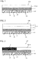
- the thermal transfer sheet 100 of the present disclosure includes a substrate 1, a back face layer 20 provided on one surface of the substrate 1, and a transfer layer 10 provided on the other surface of the substrate 1.
- the transfer layer 10 is a layer that has a single-layer or layered structure including a protective layer 5 and is to be released at the surface of the transfer layer 10 on the side of the substrate 1.
- FIGS. 1 to 3 are schematic cross-sectional views each showing an example of the thermal transfer sheet 100 of the present disclosure.
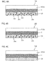
- FIGS. 4A to 4C are schematic cross-sectional views of each thermal transfer sheet 100, in which the back face layer 20 is provided on one surface of the substrate 1 and the transfer layer 10 of a single-layer structure composed only of the protective layer 5 is provided on the other surface of the substrate 1.
- FIG. 4A has a structure in which the back face layer 20 contains particles 25A and the particles 25A project from the surface of the back face layer 20.
- the thermal transfer sheet 100 of an aspect shown in FIG. 4B has a structure in which the back face layer 20 contains particles 25A and the particles 25A are present only inside the back face layer 20 without projecting from the surface of the back face layer 20.
- the thermal transfer sheet 100 of an aspect shown in FIG. 4C has a structure in which the back face layer 20 contains no particles 25A.
- FIG. 5A is a schematic cross-sectional view of a print 300 produced by transferring the transfer layer 10 (protective layer 5) of the thermal transfer sheet 100 in FIG. 4A onto a transfer receiving article 200.
- FIG. 5A is a schematic cross-sectional view of a print 300 produced by transferring the transfer layer 10 (protective layer 5) of the thermal transfer sheet 100 in FIG. 4A onto a transfer receiving article 200.
- FIG. 5B is a schematic cross-sectional view of a print 300 produced by transferring the transfer layer 10 (protective layer 5) of the thermal transfer sheet 100 in FIG. 4B onto a transfer receiving article 200.
- FIG. 5C is a schematic cross-sectional view of a print 300 produced by transferring the transfer layer 10 (protective layer 5) of the thermal transfer sheet 100 in FIG. 4C onto a transfer receiving article 200.
- irregularities developed on the surface of the transfer layer 10 after transfer are shown exaggerated.
- the transfer layer 10 is transferred onto the transfer receiving article 200 by bringing the back face layer 20 of the thermal transfer sheet into contact with a heating device (e.g., a thermal head) and applying energy to the side of the back face layer 20.
- a heating device e.g., a thermal head
- a predetermined print pressure is applied to the back face layer 20 by the heating device.
- the back face layer 20 is pushed in by the heating device. Accordingly, as shown in FIGS. 4A and 5B , when the back face layer 20 contains the particles 25A, in transferring the transfer layer 10, the particles 25A projecting from the back face layer 20 and the particles 25A present inside the back face layer are pushed into the side of the transfer layer 10 by the print pressure applied to the back face layer 20, and as shown in FIGS.
- irregularities conforming to the shape of the particles 25A contained in the back face layer 20 are likely to develop on the surface of the transfer layer 10 after transferred on the transfer receiving article 200.
- the frequency of occurrence of these irregularities tends to be higher and the magnitude of the irregularities tends to be greater, and the smoothness of the surface of the transfer layer 10 tends to be lower.
- the transfer layer 10 has a single-layer structure composed only of the protective layer 5, but the same applies to a case where the transfer layer 10 has a layered structure.
- the smoothness of the surface of the transfer layer 10 after transfer is closely related with the gloss of the transfer layer 10, in other words, the gloss of the protective layer 5.
- the lower the smoothness of the surface of the transfer layer 10 after transfer the lower the gloss.
- the gloss of the transfer layer 10 after transfer becomes lower.
- the shape of the particles 25A contained in the back face layer 20 is non-spherical, the gloss of the transfer layer 10 after transfer becomes low.
- the content of the particles 25A to be contained in the back face layer 20 and the like be considered.
- FIG. 4C when the back face layer 20 contains no particles 25A, a high gloss can be imparted to the transfer layer 10 after transfer.
- the frictional force of the back face layer becomes extremely high, wrinkles are likely to occur on the transfer layer in transferring the transfer layer, and print omission is more likely to occur, due to these wrinkles, on the transfer layer to be transferred.
- the back face layer 20 provided on one surface of the substrate 1 contains the spherical particles 25, and when the surface of the back face layer 20 is observed using a scanning electron microscope (SEM) at a magnification of 5000 times, the proportion of the total of the projected areas of the spherical particles 25 is specified to be 1.8% or more and 20% or less based on the area of the entire observed surface.
- the total of the projected areas of the spherical particles referred to herein means a summed area obtained by calculating the projected area of each spherical particle and summing up the areas.
- the thermal transfer sheet 100 of the present disclosure which includes such a back face layer, it is possible to lower the frictional force between the back face layer 20 and the heating device, in other words, to make the lubricity of the back face layer 20 good and to prevent print omission from occurring on the transfer layer. It is also possible to prevent debris of the back face from adhering to or depositing on the heating device. Further, it is possible to make the gloss of the transfer layer 10 after transfer good.
- thermal transfer sheet 100 of the present disclosure use of the thermal transfer sheet 100 can prevent print omission from occurring on the transfer layer to be transferred as well as produce a print having a good gloss.
- the back face layer 20 of a preferred aspect has a proportion of the total of the projected areas of the spherical particles 25 of 2% or more and 20% or less, more preferably of 2.3% or more and 20% or less, further preferably of 2.3% or more and 15% or less, based on the area of the entire observed surface.
- the proportion of the total of the projected areas of the spherical particles 25 based on the area of the entire observed surface during observation using a scanning electron microscope (SEM) at a magnification of 5000 times can be calculated using image analysis software (Image J, U.S. National Institute of Health). Specifically, the proportion can be obtained by calculating the projected area of each spherical particle using a scanning electron microscope (SU1510, Hitachi High-Technologies Corporation) as the scanning electron microscope (SEM), summing up the projected areas of the spherical particles to obtain the summed area, and dividing the summed area by the area of the entire observed surface.
- SEM scanning electron microscope
- the area observed with the scanning electron microscope (SEM) is the back face layer 20 overlapping the center portion of the transfer layer 10, and the size of the observed surface at the magnification of 5000 times was defined as a region having a length of 17 ⁇ m and a width of 25 ⁇ m.
- the acceleration voltage during observation was set to 5 kV.
- the back face layer was subjected to sputtering (target: Pt (platinum)) to form a Pt (platinum) thin film having a thickness of 10 nm or less.
- FIGS. 6 to 8 are SEM images during observation at a magnification of 5000 times using a scanning electron microscope (SEM).
- FIG. 6 shows a back face layer having a proportion of the total of the projected areas of the spherical particles 25 of 1.6% based on the area of the entire observed surface.
- FIG. 7 shows a back face layer having a proportion of the total of the projected areas of the spherical particles 25 of 12.6% based on the area of the entire observed surface.
- FIG. 8 shows a back face layer having a proportion of the total of the projected areas of the spherical particles 25 of 21.8% based on the area of the entire observed surface.
- the spherical particles referred to herein mean particles having a value, obtained by dividing the minimum diameter thereof by the maximum diameter thereof, of 0.7 or more, when the diameters of the particles in the SEM image during observation using a scanning electron microscope (SEM) at a magnification of 5000 times are determined, the diameter of the smallest value is taken as the minimum diameter, and the diameter of the largest value is taken as the maximum diameter.
- the diameter of the particles can be measured using the SEM image and image analysis software.
- the spherical particles include spherical talc, spherical carbon black, spherical aluminum, spherical molybdenum disulfide, spherical calcium carbonate, spherical polyethylene wax, spherical silicone resin, spherical melamine - formaldehyde condensate, spherical benzoguanamine - melamine - formaldehyde condensate, spherical benzoguanamine - formaldehyde condensate, spherical benzoguanamine - formaldehyde condensate, spherical acrylic resin, spherical styrene resin, spherical nylon resin, spherical PTFE, and spherical butadiene.
- the back face layer 20 may contain one type of spherical particles or may contain two or more types of spherical particles.
- spherical silicone resin is used to form spherical particles in respect of imparting a good gloss to the transfer layer 10 after transfer as well as better preventing print omission from occurring on the transfer layer to be transferred.
- the proportion of the number of the spherical particles having a maximum diameter of 0.1 ⁇ m or more and 3 ⁇ m or less which can be determined with the projection image and image analysis software, is preferably 80% or more, more preferably 90% or more, even more preferably 92.5% or more, based on the total number of the spherical particles projected within the observed surface.
- SEM scanning electron microscope
- the proportion of the number of the spherical particles having a particle area of 0.003 ⁇ m 2 or more and 7.5 ⁇ m 2 or less is preferably 80% or more, more preferably 90% or more, even more preferably 92.5% or more, based on the total number of the spherical particles projected within the observed surface.
- the number of the spherical particles having a maximum diameter of 0.1 ⁇ m or more and 3 ⁇ m or less is preferably 90% or more, more preferably 95% or more, even more preferably 98% or more, based on the total number of the spherical particles contained in the back face layer 20. According to the back face layer 20 of this aspect, it is possible to better prevent print omission from occurring on the transfer layer to be transferred and make the gloss of transfer layer after transfer good.
- the content of the spherical particles having a maximum diameter of 0.1 ⁇ m or more and 3 ⁇ m or less is preferably 90% by mass or more based on the total mass of the spherical particles 25 contained in the back face layer 20. According to the back face layer 20 of this aspect, it is possible to make the gloss of the transfer layer after transfer better.
- the summed mass of the spherical particles is preferably 0.5% by mass or more and 20% by mass or less, more preferably 1.5% by mass or more and less than 15% by mass, based on the total mass of the back face layer 20.
- the spherical particles are preferably spherical particles having a maximum diameter of 0.1 ⁇ m or more and 3 ⁇ m or less.
- the back face layer 20 may contain non-spherical particles along with the above spherical particles.
- the proportion of the total of the projected areas of the non-spherical particles is preferably 2% or less, more preferably 0.8% or less, even more preferably 0.5% or less, based on the area of the entire observed surface.
- the summed mass of the non-spherical particles is preferably 2% by mass or less, more preferably less than 1% by mass, even more preferably 0.8% by mass or less, based on the total mass of the back face layer 20.
- the back face layer 20 contains a resin component along with the above spherical particles.
- the resin component can include, but are not limited to, polyesters, polyacrylic esters, polyvinyl acetate, acrylic polyols, acryl - styrene copolymers, urethane resins, polyolefins such as polyethylene and polypropylene, polystyrene, polyvinyl chloride, polyethers, polyamides, polyimides, polyamideimides, polycarbonate, polyacrylamide, polyvinyl chloride, polyvinyl acetals such as polyvinyl acetoacetal and polyvinyl butyral, and silicone-modified forms of these.
- a cured resin obtained by curing such a resin component with a curing agent.
- a reaction product of a curable resin and a curing agent may be used.
- the curing agent include isocyanate-type curing agents.
- a siloxane crosslinked resin is used in the present invention. According to the back face layer 20 containing a siloxane crosslinked resin, it is possible to make the lubricity of the back face layer 20 better and sufficiently enhance the strength of the back face layer.
- the back face layer 20 due to a synergistic effect with an effect obtained by allowing the spherical particles described above to contain and, when the surface of the back face layer 20 is observed using a scanning electron microscope (SEM) at a magnification of 5000 times, setting the proportion of the total of the projected areas of the spherical particles 25 to 1.8% or more and 20% or less, based on the area of the entire observed surface, it is possible to better prevent print omission from occurring and make the gloss of the transfer layer to be transferred better.
- SEM scanning electron microscope
- enhancing the strength of the back face layer 20 enables, when the back face layer 20 is pushed in by a heating device, conformability of the back face layer 20 to the pushing-in to be lower, and as a result, it is possible to enhance the smoothness of the surface layer of the transfer layer to be transferred.
- the siloxane crosslinked resin is a crosslinked resin obtained by crosslinking (curing) an alkoxysilyl group-containing resin, and specifically a resin including a "Si-O-Si" crosslinked structure formed by hydrolysis of an alkoxysilyl group of an alkoxysilyl group-containing resin and a silanol reaction.
- alkoxysilyl group-containing resin can include alkoxysilyl group-containing acrylic resins, alkoxysilyl group-containing polyesters, alkoxysilyl group-containing epoxy resins, alkoxysilyl group-containing alkyd resins, alkoxysilyl group-containing fluorine resins, alkoxysilyl group-containing polyurethane, alkoxysilyl group-containing phenol resins, and alkoxysilyl group-containing melamine resins.
- examples of the alkoxysilyl group can include a trialkoxysilyl group, a dimethoxysilyl group, and a monoalkoxysilyl group.
- examples of a siloxane crosslinked resin to be obtained from such an alkoxysilyl group-containing resin can include siloxane crosslinked acrylic resins, siloxane crosslinked polyesters, siloxane crosslinked epoxy resins, siloxane crosslinked alkyd resins, siloxane crosslinked fluorine resins, siloxane crosslinked polyurethane, siloxane crosslinked phenol resins, and siloxane crosslinked melamine resins.
- siloxane crosslinked acrylic resin is preferred.
- a crosslinking agent (curing agent) may be used.
- the crosslinking agent may be appropriately selected in accordance with the alkoxysilyl group-containing resin.
- a zirconia-type curing agent an aluminum-type curing agent, a titanium-type curing agent, a tin-type curing agent, or the like may be used.
- the content of the curing agent there is no limitation on the content of the curing agent, and an example thereof is 0.01% by mass or more and 20% by mass or less based on the total mass of the resin composition for forming the back face layer.
- the back face layer 20 may contain one resin component or may contain two or more resin components.
- the back face layer 20 also may contain various additives.
- the additives can include a release agent such as higher fatty acid amides, phosphoric ester compounds, metal soaps, silicone oils, and surfactants.
- the thickness of the back face layer 20 there is no limitation on the thickness of the back face layer 20, and the thickness can be appropriately set within a range where the proportion of the total of the projected areas of the spherical particles 25 reaches the above proportion, based on the area of the entire observed surface when the surface of the back face layer 20 is observed using a scanning electron microscope (SEM) at a magnification of 5000 times.
- the thickness of the back face layer 20, as an example, is 0.1 ⁇ m or more and 1 ⁇ m or less.
- the back face layer 20 may be formed by dispersing or dissolving a resin component, spherical particles, and various additive to be used as required in an appropriate solvent to prepare a coating liquid for back face layer, applying the coating liquid on one surface of the substrate 1 or an optional layer provided on the one surface of the substrate 1 (e.g., a back face primer layer mentioned below), and drying the coated film.
- the coating method can include a gravure printing method, a screen printing method, and a reverse roll coating method using a gravure printing plate. Coating methods other than these methods also may be used. The same applies to coating methods for various coating liquids mentioned below.
- a back face primer layer (not shown) may be provided between the substrate 1 and the back face layer 20.
- the back face primer layer is a layer to be provided in order to improve the adhesion between the substrate 1 and the back face layer 20, being an optional constituent in the thermal transfer sheet 100 of the present disclosure.
- the resin component constituting the back face primer layer can include polyesters, polyurethane, acrylic resins, polycarbonate, polyamides, polyimides, polyamideimides, vinyl chloride - vinyl acetate copolymers, polyvinyl butyral, polyvinyl alcohol, and polyvinyl pyrrolidone.
- the substrate 1 is an essential component in the thermal transfer sheet 100 of the present disclosure and supports the above back face layer 20 provided on one surface of the substrate 1, the transfer layer 10 provided on the other surface of the substrate 1, and the like.
- the material of the substrate 1 desirably has heat resistance and mechanical characteristics.
- the substrate 1 like this can include various plastic films or sheets of polyesters such as polyethylene terephthalate, polycarbonate, polyimides, polyether imides, cellulose derivatives, polyethylene, polypropylene, styrene resins, acrylic resins, polyvinyl chloride, polyvinylidene chloride, nylon, or polyether ether ketone.
- the thickness of the substrate 1 may be appropriately selected depending on the kind of the material of the substrate, so that the strength, heat resistance and the like of the substrate sheet lie in appropriate ranges, and is generally 2.5 ⁇ m or more and 100 ⁇ m or less.
- the transfer layer 10 is provided on the other surface of the substrate 1 (the upper surface of the substrate in the aspect shown).
- the transfer layer 10 has a single-layer structure composed only of a protective layer 5 (see FIG. 1 and FIG. 3 ) or has a layered structure including a protective layer (see FIG. 2 ).
- the transfer layer 10 of the aspect shown in FIG. 2 has a layered structure of a protective layer 5 and an adhesive layer 6 which are layered in this order from the side of the substrate 1.
- the transfer layer 10 is not limited to the aspect shown and is only required to satisfy a condition of inclusion of the protective layer 5. For example, in the aspect shown in FIG.
- the transfer layer 10 may have a configuration in which a primer layer intended to improve the adhesion between the protective layer 5 and the adhesive layer 6 is provided between the protective layer 5 and the adhesive layer, or may have a configuration in which various functional layers are provided on the protective layer 5.
- the layer located nearest from the substrate 1 may be a peelable layer.
- the constituents shown in each figure may be appropriately combined.
- protective layer 5 there is no limitation on the protective layer 5, and protective layers conventionally known in the field of thermal transfer sheets can be appropriately selected and used.
- the resin component constituting the protective layer 5 can include polyesters, polystyrene, acrylic resins, polyurethane, acryl urethane, resins obtained by silicone-modifying each of these resins, cured products of an active ray-curable resin, and any blends of these resins.
- the active ray-curable resin referred to herein means a precursor or a composition before irradiated with an active ray.
- the active ray-curable resin referred to herein also means a radioactive ray which is allowed to chemically act on an active ray-curable resin to promote polymerization, specifically meaning a visible light ray, an ultraviolet ray, an X ray, an electron beam, an ⁇ ray, a ⁇ ray, a ⁇ ray, or the like.
- the protective layer 5 may contain one resin component or may contain two or more resin components. When the transfer layer 10 is caused to have a single-layer structure composed only of a protective layer 5 or when, among layers constituting the transfer layer 10, the protective layer 5 is caused to be located farthest from the substrate 1, an adhesive property may be imparted to the protective layer 5 by causing the protective layer 5 to contain a resin component having an adhesive property mentioned below.
- the protective layer 5 may contain other components along with the above resin component.
- the other components can include a filler. It is possible to improve the foil cutting property of the transfer layer 10 by causing the protective layer 5 to contain a filler.
- the filler can include organic fillers, inorganic fillers, and organic - inorganic hybrid-type fillers.
- the filler may be a powder or a sol-type one, but a powder filler is preferably used because of its wide solvent-selectivity when a coating liquid for protective layer is prepared.
- the content of the filler is preferably 10% by mass or more and 60% by mass or less, more preferably 10% by mass or more and 50% by mass or less, even more preferably 20% by mass or more and 40% by mass or less, based on the total mass of the protective layer 5.
- the thickness of the protective layer 5 is preferably 1 ⁇ m or more and 15 ⁇ m or less, more preferably 2 ⁇ m or more and 6 ⁇ m or less. Setting the thickness of the protective layer 5 within this range enables the foil cutting property to be further improved and physical durability and chemical durability imparted to a print obtained by transferring the transfer layer 10 onto a transfer receiving article to be better.
- the protective layer 5 may be formed by dissolving or dispersing a resin component and various additive to be used as required in an appropriate solvent to prepare a coating liquid for protective layer, applying the coating liquid on one surface of the substrate 1 or an optional layer provided on the one surface of the substrate 1 (e.g., a release layer mentioned below), and drying the coated liquid.
- a protective layer 5 including a cured product of an active ray-curable resin may be formed by preparing a coating liquid for protective layer including an active ray-curable resin, applying the coating liquid on the other surface of the substrate 1 or an optional layer provided on the other surface of the substrate 1 to form a coated film of a protective layer, and irradiating this coated film with an active ray to crosslink and cure the polymerization components such as the above polymerizable copolymer.
- ultraviolet irradiation is applied as active ray irradiation, conventionally known ultraviolet irradiation apparatuses can be used.
- various apparatuses such as high pressure mercury lamps, low pressure mercury lamps, carbon arcs, xenon arcs, metal halide lamps, non-electrode ultraviolet lamps, and LEDs can be used without limitation.
- a high energy-type electron beam irradiation apparatus that applies an electronic beam at an energy of 100 keV or more and 300 keV or less
- a low energy-type electron beam irradiation apparatus that applies an electronic beam at an energy of 100 keV or less, or the like can be used.
- the irradiation mode either of a scanningtype irradiation apparatus or a curtain-type irradiation apparatus may be used.
- the thickness of the protective layer 5 is generally 0.5 ⁇ m or more and 10 ⁇ m or less.
- the transfer layer 10 may have a layered structure of a protective layer 5 and an adhesive layer 6 which are layered in this order from the side of the substrate 1. According to the transfer layer 10 of this aspect, it is possible to impart better adhesion to the transfer layer 10 without causing the protective layer 5 to contain a component for imparting adhesion to a transfer receiving article (component having adhesion).
- the resin component having an adhesive layer can include resin components, such as polyurethanes, polyolefins such as ⁇ -olefin - maleic anhydride, polyesters, acrylic resins, epoxy resins, urea resins, melamine resins, phenol resins, polyvinyl acetate, vinyl chloride - vinyl acetate copolymers, and cyano acrylate.
- resin components such as polyurethanes, polyolefins such as ⁇ -olefin - maleic anhydride, polyesters, acrylic resins, epoxy resins, urea resins, melamine resins, phenol resins, polyvinyl acetate, vinyl chloride - vinyl acetate copolymers, and cyano acrylate.
- the thickness of the adhesive layer 6 is preferably 0.5 ⁇ m or more and 10 ⁇ m or less.
- the adhesive layer may be formed by dispersing or dissolving the adhesive exemplified above and additives to be added as required in an appropriate solvent to prepare a coating liquid for adhesive layer, applying this coating liquid onto the protective layer 5 or an optional layer provided on the protective layer 5, and drying the applied liquid.
- a peelable layer may be located nearest from the substrate 1 (not shown), among layers constituting the transfer layer 10.
- Examples of the resin component of the peelable layer can include ethylene - vinyl acetate copolymers, vinyl chloride - vinyl acetate copolymers, maleic acid-modified vinyl chloride - vinyl acetate copolymers, polyamides, polyesters, polyethylene, ethylene - isobutyl acrylate copolymers, butyral, polyvinyl acetate and copolymers thereof, ionomer resins, acid-modified polyolefins, (meth)acrylic resins such as acrylic type and methacrylic type, acrylic acid ester resins, ethylene - (meth)acrylic acid copolymers, ethylene - (meth)acrylic acid ester copolymers, polymethyl methacrylate, cellulose resins, polyvinyl ethers, urethane resins, polycarbonate, polypropylene, epoxy resins, phenol resins, vinyl resins, maleic acid resins, alkyd resins, polyethylene oxides, urea resins
- the thickness of the peelable layer is preferably 1 ⁇ m or more and 15 ⁇ m or less.
- a release layer (not shown) may be provided between the substrate 1 and the transfer layer 10.
- the components of the release layer can include waxes, silicone wax, silicone resins, silicone-modified resins, fluorine resins, fluorine-modified resins, polyvinyl alcohol, acrylic resin, thermally crosslinkable epoxy - amino resins, and thermally crosslinkable alkyd - amino resins.
- the thickness of the release layer is generally 0.5 ⁇ m or more and 5 ⁇ m or less.
- the release layer may be formed by dispersing or dissolving the above components in an appropriate solvent to prepare a coating liquid for release layer, applying this coating liquid onto the substrate 1, and drying the applied liquid.
- the surface of the substrate 1 on the side of the release layer may be subjected to adhesive treatment in order to improve the adhesion between the substrate 1 and the release layer.
- adhesive treatment a known resin surface modification technique, for example, corona discharge treatment, flame treatment, ozone treatment, ultraviolet treatment, radiation treatment, roughening treatment, chemical treatment, plasma treatment, low-temperature treatment, primer treatment, and grafting treatment, can be applied as it is. Two or more of these treatments also can be used in combination.
- a colorant layer 7 may be provided on the other surface of the substrate 1 so as to be frame sequential to the transfer layer 10 described above.
- a single colorant layer 7 is provided on the other surface of the substrate 1 (a portion of the upper face of the substrate 1 in the aspect shown).
- a plurality of colorant layers for example, a yellow colorant layer, a magenta colorant layer, a cyan colorant layer, a black colorant layer, and the like may be provided in a frame-sequential manner.
- thermal transfer sheet of the aspect shown in FIG. 3 it is possible to form a thermal transferred image on a transfer receiving article and transfer the transfer layer 10 onto the formed thermal transferred image using one thermal transfer sheet 100. Additionally, when a thermal transferred image is formed, it is possible to prevent print omission from occurring on the thermal transferred image by means of the back face layer 20 described above. In other words, according to the thermal transfer sheet of the aspect shown in FIG. 3 , it is possible to prevent print omission from occurring on both the thermal transferred image to be formed and the transfer layer to be transferred and make the gloss of the transfer layer to be transferred well.
- the thermal transfer sheet 100 of the present disclosure having the colorant layer 7 may be a thermal transfer sheet 100 to be used for forming a thermal transferred image by a sublimation-type thermal transfer method or may be a thermal transfer sheet 100 to be used for forming a thermal transferred image by a melt-type thermal transfer method.
- a binder resin contained in the colorant layer 7 to be used for the sublimation-type thermal transfer method can include resin components including cellulosic resins, such as ethyl cellulose, hydroxyethyl cellulose, ethyl hydroxy cellulose, methyl cellulose, and cellulose acetate, vinyl resins such as polyvinyl alcohol, polyvinyl acetate, polyvinyl butyral, polyvinyl acetoacetal, and polyvinyl pyrrolidone, acrylic resins such as poly(meth)acrylate and poly(meth)acrylamide, urethane resins, polyamides, and polyesters.
- cellulosic resins such as ethyl cellulose, hydroxyethyl cellulose, ethyl hydroxy cellulose, methyl cellulose, and cellulose acetate
- vinyl resins such as polyvinyl alcohol, polyvinyl acetate, polyvinyl butyral, polyvinyl acetoacetal, and poly
- the content of the binder resin is preferably 20% by mass or more based on the total mass of the colorant layer 7. Setting the content of the binder resin to 20% by mass or more based on the total mass of the colorant layer 7 enables a sublimable dye to be sufficiently maintained in the colorant layer 7 to thereby result in an improvement in storage stability.
- the upper limit of the content of the binder resin is only required to be determined in accordance with the content of the sublimable dye and optional additives.
- the colorant layer 7 to be used for the sublimation-type thermal transfer method contains a sublimable dye as the colorant component.
- a sublimable dye there is no particular limitation on the sublimable dye, and sublimable dyes having a sufficient color density and not discoloring and fading due to light, heat, temperature, and the like are preferred.
- the dye can include diarylmethane-type dyes, triarylmethane-type dyes, thiazole-type dyes, merocyanine dyes, pyrazolone dyes, methine-type dyes, indoaniline-type dyes, azomethine-type dyes such as acetophenoneazomethine, pyrazoloazomethine, imidazoleazomethine, imidazoazomethine, and pyridoneazomethine, xanthene-type dyes, oxazine-type dyes, dicyanostyrene-type dyes such as dicyanostyrene and tricyanostyrene, thiazine-type dyes, azine-type dyes, acridine-type dyes, benzeneazo-type dyes, azo-type dyes such as pyridoneazo, thiopheneazo, isothiazoleazo, pyrroleazo, pyrrazole
- red dyes such as MS Red G (Mitsui Toatsu Kagaku Kabushiki Kaisha), Macrolex Red Violet R (Bayer AG), Ceres Red 7B (Bayer AG), and Samaron Red F3BS (Mitsubishi Chemical Corporation), yellow dyes such as Foron Brilliant Yellow 6GL (Clariant GmbH), PTY-52 (Mitsubishi Chemical Corporation), and Macrolex yellow 6G (Bayer AG), and blue dyes such as Kayaset(R) Blue 714 (NIPPON KAYAKU Co., Ltd.), Foron Brilliant Blue S-R (Clariant GmbH), MS Blue 100 (Mitsui Toatsu Kagaku Kabushiki Kaisha), and C.I. Solvent 63.
- red dyes such as MS Red G (Mitsui Toatsu Kagaku Kabushiki Kaisha), Macrolex Red Violet R (Bayer AG), Ceres Red 7B (Bayer AG), and Samaron Red F3BS (Mitsubishi Chemical Corporation)
- yellow dyes such
- the content of the sublimable dye is preferably 50% by mass or more and 350% by mass or less, more preferably 80% by mass or more and 300% by mass or less, based on the total mass of the binder resin. Setting the content of the sublimable dye to the preferred content described above enables the print density and storage stability to be further improved.
- a colorant primer layer (not shown), which is intended for improving the adhesion between the substrate 1 and the colorant layer 7, may be provided between the substrate 1 and the colorant layer 7.
- An exemplary colorant primer layer is constituted by a resin component.
- the resin component constituting the colorant primer layer can include resin components such as polyesters, polyvinyl pyrrolidone, polyvinyl alcohol, polyacrylic esters, polyvinyl acetate, urethane resins, styrene acrylate, polyacrylamide, polyamides, polyvinyl acetoacetal, and polyvinyl butyral.
- the colorant primer layer may also contain various additives such as organic particles and inorganic particles along with the resin component.
- the colorant primer layer may be formed by dispersing or dissolving the resin component exemplified above and additives to be added as required in an appropriate solvent to prepare a coating liquid for colorant primer layer, applying this coating liquid onto the substrate 1, and drying the applied liquid.
- the thickness of the colorant primer layer is generally 0.02 ⁇ m or more and 1 ⁇ m or less.
- the colorant layer to be used for the melt-type thermal transfer method contains a coloring agent and a binder.
- a wax component that can be used as the binder can include various waxes such as microcrystalline wax, carnauba wax, paraffin wax, Fischer-Tropsch wax, various low molecular weight polyethylenes, Japan wax, beeswax, spermaceti, Chinese wax, wool wax, shellac wax, candelilla wax, petrolatum, polyester wax, partially-modified wax, fatty acid esters, and fatty acid amides.
- Examples of a resin component that can be used as the binder can include ethylene - vinyl acetate copolymers, ethylene - acrylic acid ester copolymers, polyethylene, polystyrene, polypropylene, polybutene, petroleum resins, vinyl chloride resins, vinyl chloride - vinyl acetate copolymers, polyvinyl alcohol, vinylidene chloride resins, acrylic resins, methacrylic resins, polyamides, polycarbonate, fluorine resins, polyvinyl formal, polyvinyl butyral, acetyl cellulose, nitrocellulose, polyvinyl acetate, polyisobutylene, ethyl cellulose, and polyvinyl acetoacetal.
- the coloring agent may be appropriately selected from known organic or inorganic pigments or dyes, and for example, coloring agents having a sufficient color density and not discoloring and fading due to light, heat, and the like are preferred.
- the coloring agent may be a material that develops color by heating or a material that develops color when brought into contact with a component applied on the surface of a transfer receiving article. Further, the color of the coloring agent is not limited to cyan, magenta, yellow, and black, and coloring agents of various colors can be used.
- Examples of the transfer receiving article onto which the transfer layer 10 of the thermal transfer sheet 100 of the present disclosure is to be transferred include thermal transfer image-receiving sheets, plain paper, wood-free paper, tracing paper, plastic films, and plastic cards mainly composed of vinyl chloride, a vinyl chloride-vinyl acetate copolymer, or polycarbonate.
- the transfer receiving article one having a predetermined image also can be used.
- the transfer receiving article may be colored or may have transparency.
- a method for transferring the transfer layer onto a transfer receiving article can be performed using, for example, a thermal transfer printer having a heating device such as a thermal head, or a heating device such as a hot stamp or a heat roll.
- the thermal transfer sheet 100 of the present disclosure which enables prevention of occurrence of print omission on the transfer layer to be transferred, can be suitably used in combination with a thermal transfer printer having a heating device such as a thermal head, which printer is likely to cause print omission in comparison with a hot stamp, a heat roll, or the like.
- each of these resins may be a homopolymer of a monomer constituting each resin, or a copolymer of the main component monomer constituting each resin and one or more other polymers, or a derivative thereof.
- a reference to an acrylic resin is only required to include a monomer of acrylic acid or methacrylic acid, or an acrylic acid ester or methacrylic acid ester as the main component.
- the acrylic resin also may be a modified product of these resins.
- a resin component other than those described herein also may be used.
- Example 12 is a worked example according to the invention as claimed in appended claim 1.
- Examples 1 to 11, 13 and 14 are Reference Examples.
- a polyethylene terephthalate film having a thickness of 4.5 ⁇ m was used as a substrate.
- a coating liquid for back face primer layer having the following composition was applied, and the applied liquid was dried to form a back face primer layer having a thickness of 0.1 ⁇ m.
- a coating liquid for back face layer having the following composition was applied on this back face primer layer, and the applied liquid was dried to form a back face layer having a thickness of 0.4 ⁇ m.
- a coating liquid for colorant primer layer having the following composition was applied, and the applied liquid was dried to from a colorant primer layer having a thickness of 0.25 ⁇ m.
- a coating liquid for yellow colorant layer, a coating liquid for magenta colorant layer, and a coating liquid for cyan colorant layer having the following composition were applied on this colorant primer layer, and the applied liquids were dried to form a colorant layer, in which a yellow colorant layer, a magenta colorant layer, and a cyan colorant layer each having a thickness of 0.5 ⁇ m were provided in this order in a frame-sequential manner. Additionally, on a portion of the other surface of the substrate, a coating liquid for peelable layer having the following composition was applied, and the applied liquid was dried to form a peelable layer having a thickness of 1 ⁇ m.
- a coating liquid for protective layer having the following composition was applied on the peelable layer, the applied liquid was dried to from a protective layer having a thickness of 2 ⁇ m, and thus, a thermal transfer sheet of Example 1 was prepared.
- the peelable layer and the protective layer constitute the transfer layer of the thermal transfer sheet of the present disclosure.
- Alumina sol (Alumina sol 200, Nissan Chemical Industries, Ltd.) 4 parts Cationic urethane resin (SF-600, Dai-ichi Kogyo Seiyaku, Co., Ltd.) 6 parts Water 100 parts Isopropyl alcohol 100 parts
- Disperse dye (Foron Brilliant Yellow S-6GL) 5.5 parts Polyvinyl acetoacetal 4.5 parts (S-LEC(R) KS-5, SEKISUI CHEMICAL CO., LTD.) Phosphoric ester type surfactant 0.1 part (PLYSURF(R) A208N, Dai-ichi Kogyo Seiyaku, Co., Ltd.) Epoxy-modified silicone oil 0.04 parts (KF-101, manufactured by Shin-Etsu Chemical Co., Ltd.) Polyethylene wax 0.1 part Methyl ethyl ketone 45 parts Toluene 45 parts
- Disperse dye MS Red G
- Disperse dye Macrolex Red Violet R
- Polyvinyl acetoacetal S-LEC(R) KS-5, SEKISUI CHEMICAL CO., LTD.
- Phosphoric ester type surfactant PLYSURF(R) A208N, Dai-ichi Kogyo Seiyaku, Co., Ltd.
- Polyethylene wax 0.1 part Epoxy-modified silicone oil (KF-101, manufactured by Shin-Etsu Chemical Co., Ltd.) 0.04 parts Methyl ethyl ketone 45 parts Toluene 45 parts
- Disperse dye Solvent Blue 63
- Disperse dye HBV-2194
- Polyvinyl acetoacetal S-LEC(R) KS-5, SEKISUI CHEMICAL CO., LTD.
- Phosphoric ester type surfactant PLYSURF(R) A208N, Dai-ichi Kogyo Seiyaku, Co., Ltd.
- Polyethylene wax 0.1 part Epoxy-modified silicone oil (KF-101, manufactured by Shin-Etsu Chemical Co., Ltd.) 0.04 parts Methyl ethyl ketone 45 parts Toluene 45 parts
- Acrylic resin (DIANAL(R) BR-87, Mitsubishi Chemical Corporation) 29 parts Polyester (Vylon(R) 200, TOYOBO CO., LTD.) 1 part Methyl ethyl ketone 35 parts Toluene 35 parts
- Polyester (Vylon(R) 200, TOYOBO CO., LTD.) 30 parts Methyl ethyl ketone 35 parts Toluene 35 parts
- Polyester solid content: 30%
- POLYESTER(R) WR-961 The Nippon Synthetic Chemical Industry Co., Ltd.
- a thermal transfer sheet of Example 2 was obtained exactly in the same manner as in Example 1 except that the coating liquid for back face layer 1 was replaced by a coating liquid for back face layer 2 having the following composition to form the back face layer.
- a thermal transfer sheet of Example 3 was obtained exactly in the same manner as in Example 1 except that the coating liquid for back face layer 1 was replaced by a coating liquid for back face layer 3 having the following composition to form the back face layer.
- a thermal transfer sheet of Example 4 was obtained exactly in the same manner as in Example 1 except that the coating liquid for back face layer 1 was replaced by a coating liquid for back face layer 4 having the following composition to form the back face layer.
- a thermal transfer sheet of Example 5 was obtained exactly in the same manner as in Example 1 except that the coating liquid for back face layer 1 was replaced by a coating liquid for back face layer 5 having the following composition to form the back face layer.
- a thermal transfer sheet of Example 6 was obtained exactly in the same manner as in Example 1 except that the coating liquid for back face layer 1 was replaced by a coating liquid for back face layer 6 having the following composition to form the back face layer.
- a thermal transfer sheet of Example 7 was obtained exactly in the same manner as in Example 1 except that the coating liquid for back face layer 1 was replaced by a coating liquid for back face layer 7 having the following composition to form the back face layer.
- Polyvinyl butyral 26 parts (S-LEC(R) BX-1, SEKISUI CHEMICAL CO., LTD.) Curing agent (polyisocyanate) (solid content: 75%) 219 parts (BURNOCK(R) D750, DIC Corporation) Spherical silicone resin (average particle size: 0.7 ⁇ m) 4 parts (X-52-854, manufactured by Shin-Etsu Chemical Co., Ltd.) Silicone oil (solid content: 30%) 20 parts (MODIPER(R) FS730, NOF CORPORATION) Toluene 366 parts Methyl ethyl ketone 366 parts
- a thermal transfer sheet of Example 8 was obtained exactly in the same manner as in Example 1 except that the coating liquid for back face layer 1 was replaced by a coating liquid for back face layer 8 having the following composition to form the back face layer.
- Example 9 A thermal transfer sheet of Example 9 was obtained exactly in the same manner as in Example 1 except that the coating liquid for back face layer 1 was replaced by a coating liquid for back face layer 9 having the following composition to form the back face layer.
- a thermal transfer sheet of Example 10 was obtained exactly in the same manner as in Example 1 except that the coating liquid for back face layer 1 was replaced by a coating liquid for back face layer 10 having the following composition to form the back face layer.
- Example 11 A thermal transfer sheet of Example 11 was obtained exactly in the same manner as in Example 1 except that the coating liquid for back face layer 1 was replaced by a coating liquid for back face layer 11 having the following composition to form the back face layer.
- a thermal transfer sheet of Example 12 was obtained exactly in the same manner as in Example 1 except that the coating liquid for back face layer 1 was replaced by a coating liquid for back face layer 12 having the following composition to form the back face layer.
- a thermal transfer sheet of Example 13 was obtained exactly in the same manner as in Example 1 except that the coating liquid for back face layer 1 was replaced by a coating liquid for back face layer 13 having the following composition to form the back face layer.
- Acrylic polyol solid content: 36.5%
- Curing agent polyisocyanate
- solid content: 75%) BURNOCK(R) D750, DIC Corporation
- Spherical silicone resin average particle ⁇ m)size: 0.7 10 parts
- X-52-854 manufactured by Shin-Etsu Chemical Co., Ltd.
- Silicone oil solid content: 30%) 20 parts (MODIPER(R) FS730, NOF CORPORATION) Methyl ethyl ketone 268 parts Toluene 268 parts
- a thermal transfer sheet of Example 14 was obtained exactly in the same manner as in Example 1 except that the coating liquid for back face layer 1 was replaced by a coating liquid for back face layer 14 having the following composition to form the back face layer.
- Acrylic resin 184 parts (DIANAL(R) BR-80, Mitsubishi Chemical Corporation) Spherical silicone resin (average particle ⁇ m)size: 0.7 (X-52-854, manufactured by Shin-Etsu Chemical Co., Ltd.) 10 parts Silicone oil (solid content: 30%) 20 parts (MODIPER(R) FS730, NOF CORPORATION) Toluene 393 parts Methyl ethyl ketone 393 parts
- a thermal transfer sheet of Comparative Example 1 was obtained exactly in the same manner as in Example 1 except that the coating liquid for back face layer 1 was replaced by a coating liquid for back face layer A having the following composition to form the back face layer.
- Polyvinyl butyral 24 parts (S-LEC(R) BX-1, SEKISUI CHEMICAL CO., LTD.) Polyisocyanate 213 parts (BURNOCK(R) D750, DIC Corporation) Polygonal shape talc (average particle size: 1 ⁇ m) 10 part (SG-2000, Nippon Talc Co., Ltd.) Silicone oil (solid content: 30%) 20 parts (MODIPER(R) FS730, NOF CORPORATION) Toluene 366 parts Methyl ethyl ketone 366 parts
- a thermal transfer sheet of Comparative Example 2 was obtained exactly in the same manner as in Example 1 except that the coating liquid for back face layer 1 was replaced by a coating liquid for back face layer B having the following composition to form the back face layer.
- Polyvinyl butyral 24 parts (S-LEC(R) BX-1, SEKISUI CHEMICAL CO., LTD.) Polyisocyanate 213 parts (BURNOCK(R) D750, DIC Corporation) Polygonal shape silicone resin (average particle size: 4 ⁇ m) 10 parts (Tospearl 240, Momentive Performance Materials Japan LLC) Silicone oil (solid content: 30%) 20 parts (MODIPER(R) FS730, NOF CORPORATION) Toluene 366 parts Methyl ethyl ketone 366 parts
- a thermal transfer sheet of Comparative Example 3 was obtained exactly in the same manner as in Example 1 except that the coating liquid for back face layer 1 was replaced by a coating liquid for back face layer C having the following composition to form the back face layer.
- Polyvinyl butyral 27 parts (S-LEC(R) BX-1, SEKISUI CHEMICAL CO., LTD.) Polyisocyanate 221 parts (BURNOCK(R) D750, DIC Corporation) Spherical silicone resin (average particle size: ⁇ m) 0.7 1 part (X-52-854, manufactured by Shin-Etsu Chemical Co., Ltd.) Silicone oil (solid content: 30%) 20 parts (MODIPER(R) FS730, NOF CORPORATION) Toluene 366 parts Methyl ethyl ketone 366 parts
- a thermal transfer sheet of Comparative Example 4 was obtained exactly in the same manner as in Example 1 except that the coating liquid for back face layer 1 was replaced by a coating liquid for back face layer D having the following composition to form the back face layer.
- Polyvinyl butyral 22 parts (S-LEC(R) BX-1, SEKISUI CHEMICAL CO., LTD.) Polyisocyanate 176 parts (BURNOCK(R) D750, DIC Corporation) Spherical silicone resin (average particle size: ⁇ m) 0.7 40 parts (X-52-854, manufactured by Shin-Etsu Chemical Co., Ltd.) Silicone oil (solid content: 30%) 20 parts (MODIPER(R) FS730, NOF CORPORATION) Toluene 371 parts Methyl ethyl ketone 371 parts
- the surface of the back face layer around the center with respect to the slit width of the thermal transfer sheet in the portion of the back face layer overlapping the transfer layer was observed with a scanning electron microscope (SU1510, Hitachi High-Technologies Corporation) at a magnification of 5000 times.
- the projected area of each spherical particles was calculated using image analysis software (Image J, U.S. National Institute of Health), and the projected areas of spherical particles were summed up into the summed area of spherical particles.
- the summed area of the spherical particles was divided by the area of the entire observed surface to calculate the ratio of area occupied by the spherical particles (%).
- Table 1 the column of "Ratio of area occupied (spherical particles)" in Table 1).
- the projected areas of all the particles including spherical particles and non-spherical particles of the thermal transfer sheets of Examples 9 and 11 were each calculated in the same manner as for the calculation of ratio of area occupied by spherical particles described above. All the projected areas were summed up into the summed area of all the particles, and the projected areas of the spherical particles were summed up into the summed area of the spherical particles. The summed area of spherical particles was subtracted from the summed area of all the particles to obtain the summed area of the non-spherical particles (the area obtained by summing up of the projected areas of the non-spherical particles).
- the summed area of the non-spherical particles was divided by the area of the entire observed surface to calculate the ratio of area occupied by the non-spherical particles (%).
- the calculation results are shown in Table 1 (the column of "Ratio of area occupied (non-spherical particles)" in Table 1).
- the ratio of area occupied by non-spherical particles of any of the thermal transfer sheets of Examples 1 to 8, 10, 12 to 14 and Comparative Examples 3 and 4, in which the back face layer contains no non-spherical particles, is 0%.
- the ratio of area occupied by non-spherical particles of the thermal transfer sheets of each of Comparative Examples 1 and 2 has not been calculated.
- the surface of the back face layer around the center with respect to the slit width of the thermal transfer sheet was observed with a scanning electron microscope (SU1510, Hitachi High-Technologies Corporation) at a magnification of 5000 times.
- Image analysis software (Image J, U.S. National Institute of Health) was used to count the total number of the spherical particles projected on the observed surface (A) and the summed number of spherical particles having a maximum diameter of 0.1 ⁇ m or more and 3 ⁇ m or less (B) determined from the projection image of the observed surface.
- This summed number (B) was divided by the total number of the spherical particles within the observed surface (A) to calculate the proportion occupied by the spherical particles having a maximum diameter of 0.1 ⁇ m or more and 3 ⁇ m or less.
- the calculation results are shown in Table 1 (the column “Proportion” in Table 1).
- a black solid image was printed on a genuine image receiving sheet of the sublimable-type thermal transfer printer as a transfer receiving article under the default conditions of the printer to obtain an image-formed product. Then, by use of the above sublimable-type thermal transfer printer, the transfer layer of the thermal transfer sheet of each of Examples and Comparative Examples was transferred onto the image-formed product obtained above under the default conditions of the printer to obtain a print of each of Examples and Comparative Examples, in which the image-formed product was formed on the transfer receiving article and the transfer layer was formed on this image-formed product.
- DS40 Dai Nippon Printing Co., Ltd.
- the glossiness in the scanning direction is 59 or more, and the glossiness in the sub-scanning direction is 50 or more.
- the glossiness in the scanning direction is 57 or more and less than 59, and the glossiness in the sub-scanning direction is 48 or more, or the glossiness in the scanning direction is 57 or more, and the glossiness in the sub-scanning direction is 48 or more and less than 50.
- the glossiness in the scanning direction is less than 57, or the glossiness in the sub-scanning direction is less than 48.
- Print omission on the transfer layer occurs in two or more of the prints.
- NG Print omission on image-formed product occurs in two or more of the prints.
Landscapes
- Physics & Mathematics (AREA)
- Optics & Photonics (AREA)
- Thermal Transfer Or Thermal Recording In General (AREA)
Claims (4)
- Thermotransferbogen (100), wobeieine Rückseitenschicht (20) auf einer Oberfläche eines Substrats (1) vorgesehen ist und eine Transferschicht (10) auf der anderen Oberfläche des Substrats (1) vorgesehen ist,die Transferschicht (10) eine einschichtige Struktur oder eine geschichtete Struktur aufweist, die eine Schutzschicht (5) umfasst,die Rückseitenschicht (20) kugelförmige Teilchen (25) und ein vernetztes Siloxanharz enthält undwenn die Oberfläche der Rückseitenschicht (20) unter Verwendung eines Rasterelektronenmikroskops (SEM) bei 5000-facher Vergrößerung betrachtet wird, ein Anteil der Gesamtheit der projizierten Flächen der kugelförmigen Teilchen bezogen auf die Fläche der gesamten betrachteten Oberfläche 1,8 % oder mehr und 20 % oder weniger beträgt,wobei die kugelförmigen Teilchen (25) kugelförmiges Silikonharz sind unddas vernetzte Siloxanharz durch Vernetzen eines alkosilylgruppenhaltigen Harzes erhalten ist.
- Thermotransferbogen (100) nach Anspruch 1, wobei ein Anteil einer Anzahl von kugelförmigen Teilchen (25) mit einer maximalen Teilchengröße von 0,1 µm oder mehr und 3 µm oder weniger, die aus einem Projektionsbild der betrachteten Oberfläche bestimmt werden kann, bezogen auf eine Gesamtzahl der in der betrachteten Oberfläche betrachteten kugelförmigen Teilchen (25) 80 % oder mehr beträgt.
- Thermotransferbogen (100) nach Anspruch 1 oder 2, wobei ein Gehalt der kugelförmigen Teilchen (25) mit einem maximalen Durchmesser von 0,1 µm oder mehr und 3 µm oder weniger bezogen auf eine Gesamtmasse der in der Rückseitenschicht (20) enthaltenen kugelförmigen Teilchen (25) 90 Massen-% oder mehr beträgt.
- Thermotransferbogen (100) nach einem der Ansprüche 1 bis 3, wobei das alkosilylgruppenhaltige Harz ein alkosilylgruppenhaltiges Acrylharz ist.
Applications Claiming Priority (3)
| Application Number | Priority Date | Filing Date | Title |
|---|---|---|---|
| JP2018125587 | 2018-06-29 | ||
| JP2018185363 | 2018-09-28 | ||
| PCT/JP2019/025679 WO2020004576A1 (ja) | 2018-06-29 | 2019-06-27 | 熱転写シート |
Publications (3)
| Publication Number | Publication Date |
|---|---|
| EP3798014A1 EP3798014A1 (de) | 2021-03-31 |
| EP3798014A4 EP3798014A4 (de) | 2021-08-18 |
| EP3798014B1 true EP3798014B1 (de) | 2022-07-20 |
Family
ID=68986596
Family Applications (1)
| Application Number | Title | Priority Date | Filing Date |
|---|---|---|---|
| EP19826490.5A Active EP3798014B1 (de) | 2018-06-29 | 2019-06-27 | Wärmeübertragungsfolie |
Country Status (4)
| Country | Link |
|---|---|
| US (1) | US11981156B2 (de) |
| EP (1) | EP3798014B1 (de) |
| JP (1) | JP6870781B2 (de) |
| WO (1) | WO2020004576A1 (de) |
Families Citing this family (1)
| Publication number | Priority date | Publication date | Assignee | Title |
|---|---|---|---|---|
| JP2021122993A (ja) * | 2020-02-03 | 2021-08-30 | 大日本印刷株式会社 | 熱転写シート、及び印画物の製造方法 |
Family Cites Families (36)
| Publication number | Priority date | Publication date | Assignee | Title |
|---|---|---|---|---|
| US4735860A (en) | 1985-12-06 | 1988-04-05 | Dai Nippon Insatsu Kabushiki Kaisha | Heat-resistant, thermal-sensitive transfer sheet |
| JPH01218887A (ja) | 1988-02-29 | 1989-09-01 | Ricoh Co Ltd | 熱転写記録媒体 |
| JP2969661B2 (ja) | 1989-08-02 | 1999-11-02 | 三菱化学株式会社 | 熱転写記録用シート |
| JPH04329194A (ja) | 1991-04-30 | 1992-11-17 | Dainippon Printing Co Ltd | 熱転写シート |
| JP3276993B2 (ja) | 1992-08-03 | 2002-04-22 | 大日本印刷株式会社 | 受容層転写シート及び受容層転写方法 |
| JPH0699670A (ja) | 1992-09-21 | 1994-04-12 | Dainippon Printing Co Ltd | 熱転写シート |
| EP0629513B1 (de) | 1993-06-18 | 1997-09-10 | Dai Nippon Printing Co., Ltd. | Wärmeübertragungsblatt |
| JP3345675B2 (ja) | 1993-06-18 | 2002-11-18 | 大日本印刷株式会社 | 熱転写シート |
| JPH08150787A (ja) * | 1994-09-30 | 1996-06-11 | Mitsubishi Chem Corp | 熱転写記録用シート |
| JPH091942A (ja) | 1995-06-16 | 1997-01-07 | Mitsubishi Chem Corp | 昇華型転写記録用シート |
| JPH09123624A (ja) * | 1995-11-02 | 1997-05-13 | Mitsubishi Chem Corp | 熱転写記録用シート |
| JPH09123625A (ja) | 1995-11-07 | 1997-05-13 | Mitsubishi Chem Corp | 熱転写記録用シート |
| JP4291452B2 (ja) | 1998-03-27 | 2009-07-08 | 大日本印刷株式会社 | 熱転写シート |
| JP2000079768A (ja) | 1998-09-04 | 2000-03-21 | Unitika Ltd | 熱転写記録用シート |
| JP3863302B2 (ja) | 1998-09-30 | 2006-12-27 | 大日本印刷株式会社 | 熱転写シート |
| JP2000272254A (ja) | 1999-03-29 | 2000-10-03 | Dainippon Printing Co Ltd | 熱転写シート |
| JP2000326641A (ja) | 1999-05-20 | 2000-11-28 | Dainippon Printing Co Ltd | 熱転写シート |
| JP2001328359A (ja) | 2000-05-23 | 2001-11-27 | Sony Corp | 熱転写シート |
| JP2002240404A (ja) | 2001-02-19 | 2002-08-28 | Dainippon Printing Co Ltd | 保護層転写シート及び印画物 |
| JP4192242B2 (ja) | 2004-03-19 | 2008-12-10 | フジコピアン株式会社 | 保護層転写シート |
| JP4429248B2 (ja) | 2005-09-30 | 2010-03-10 | 大日本印刷株式会社 | 熱転写シート及びその製造方法 |
| JP4748394B2 (ja) | 2006-05-17 | 2011-08-17 | 大日本印刷株式会社 | 昇華転写シート |
| JP2009073102A (ja) | 2007-09-21 | 2009-04-09 | Ricoh Co Ltd | 熱転写記録媒体 |
| EP2075139B1 (de) | 2007-12-28 | 2010-09-15 | FUJIFILM Corporation | Verfahren zur Bildgebung mittels wärmeempfindlichem Übertragungssystem |
| JP5024202B2 (ja) | 2008-04-17 | 2012-09-12 | 大日本印刷株式会社 | 長尺体積ホログラム層転写箔、および、これを用いた体積ホログラム積層体の製造方法 |
| JP2010052364A (ja) | 2008-08-29 | 2010-03-11 | Sony Corp | 熱転写シート |
| JP4826628B2 (ja) * | 2008-12-18 | 2011-11-30 | ソニー株式会社 | 熱転写シート |
| JP4962504B2 (ja) * | 2009-02-04 | 2012-06-27 | ソニー株式会社 | 熱転写シート |
| JP5573274B2 (ja) | 2010-03-25 | 2014-08-20 | 大日本印刷株式会社 | 熱転写シート |
| JP5772010B2 (ja) | 2011-01-26 | 2015-09-02 | ソニー株式会社 | 熱転写シート |
| WO2012115202A1 (ja) | 2011-02-24 | 2012-08-30 | 大日本印刷株式会社 | 熱転写シート |
| JP2013010312A (ja) | 2011-06-30 | 2013-01-17 | Dainippon Printing Co Ltd | 画像形成方法 |
| JP5553098B2 (ja) | 2011-09-30 | 2014-07-16 | 大日本印刷株式会社 | 熱転写シート |
| JP2014188894A (ja) | 2013-03-27 | 2014-10-06 | Dainippon Printing Co Ltd | 熱転写シート |
| JP6651700B2 (ja) | 2015-03-10 | 2020-02-19 | 凸版印刷株式会社 | 熱転写シート |
| JP2017052141A (ja) | 2015-09-08 | 2017-03-16 | 凸版印刷株式会社 | 昇華性熱転写記録媒体 |
-
2019
- 2019-06-27 JP JP2020527652A patent/JP6870781B2/ja active Active
- 2019-06-27 EP EP19826490.5A patent/EP3798014B1/de active Active
- 2019-06-27 US US16/972,745 patent/US11981156B2/en active Active
- 2019-06-27 WO PCT/JP2019/025679 patent/WO2020004576A1/ja not_active Ceased
Also Published As
| Publication number | Publication date |
|---|---|
| EP3798014A1 (de) | 2021-03-31 |
| JPWO2020004576A1 (ja) | 2021-03-11 |
| WO2020004576A1 (ja) | 2020-01-02 |
| JP6870781B2 (ja) | 2021-05-12 |
| US20210260906A1 (en) | 2021-08-26 |
| EP3798014A4 (de) | 2021-08-18 |
| US11981156B2 (en) | 2024-05-14 |
Similar Documents
| Publication | Publication Date | Title |
|---|---|---|
| EP1637340A1 (de) | Thermisches Transferblatt | |
| EP1980408A2 (de) | Wärmeempfindliche Übertragungsfolie und bildgebendes Verfahren | |
| EP3348413B1 (de) | Übertragungsblatt | |
| JP7356084B2 (ja) | 熱転写シート | |
| EP3698981A1 (de) | Wärmetransferfolie und kombination von wärmetransferfolie und zwischentransfermedium | |
| EP2805830B1 (de) | Zwischenübertragungsmedium | |
| CA2470766A1 (en) | Multicolor image forming material and multicolor image forming method | |
| US6758932B2 (en) | Multicolor image forming material and method for forming multicolor image | |
| EP1958787A1 (de) | Wärmeübertragungsblatt | |
| EP1243438B1 (de) | Thermisches Übertragungsaufzeichnungsverfahren durch Laser und Vorrichtung | |
| EP2030798B1 (de) | Wärmeempfindliches Übertragungsblatt | |
| EP1228893B1 (de) | Bildaufzeichnungsmaterial und Bildaufzeichnungsverfahren | |
| EP3798014B1 (de) | Wärmeübertragungsfolie | |
| JP6024513B2 (ja) | 中間転写媒体 | |
| EP2942202A1 (de) | Wärmetransferbildempfangsfolie und bilderzeugungsverfahren | |
| EP3950371B1 (de) | Thermische übertragungsschicht | |
| EP3753745B1 (de) | Übertragungsblatt mit schutzschicht | |
| JP7200609B2 (ja) | 熱転写シート | |
| US6824845B2 (en) | Multicolor image-forming material and method for forming multicolor image | |
| EP1238817A2 (de) | Mehrfarbiges Bilderzeugungsmaterial und mehrfarbiges Bilderzeugungsverfahren | |
| JP2005103893A (ja) | 画像形成材料及び画像形成方法 | |
| JP2019064033A (ja) | 熱転写受像シートと熱転写シートとの組み合わせ |
Legal Events
| Date | Code | Title | Description |
|---|---|---|---|
| STAA | Information on the status of an ep patent application or granted ep patent |
Free format text: STATUS: THE INTERNATIONAL PUBLICATION HAS BEEN MADE |
|
| PUAI | Public reference made under article 153(3) epc to a published international application that has entered the european phase |
Free format text: ORIGINAL CODE: 0009012 |
|
| STAA | Information on the status of an ep patent application or granted ep patent |
Free format text: STATUS: REQUEST FOR EXAMINATION WAS MADE |
|
| 17P | Request for examination filed |
Effective date: 20201223 |
|
| AK | Designated contracting states |
Kind code of ref document: A1 Designated state(s): AL AT BE BG CH CY CZ DE DK EE ES FI FR GB GR HR HU IE IS IT LI LT LU LV MC MK MT NL NO PL PT RO RS SE SI SK SM TR |
|
| AX | Request for extension of the european patent |
Extension state: BA ME |
|
| A4 | Supplementary search report drawn up and despatched |
Effective date: 20210719 |
|
| RIC1 | Information provided on ipc code assigned before grant |
Ipc: B41M 5/382 20060101AFI20210713BHEP Ipc: B41M 5/42 20060101ALI20210713BHEP Ipc: B41M 5/44 20060101ALN20210713BHEP |
|
| DAV | Request for validation of the european patent (deleted) | ||
| DAX | Request for extension of the european patent (deleted) | ||
| GRAP | Despatch of communication of intention to grant a patent |
Free format text: ORIGINAL CODE: EPIDOSNIGR1 |
|
| STAA | Information on the status of an ep patent application or granted ep patent |
Free format text: STATUS: GRANT OF PATENT IS INTENDED |
|
| RIC1 | Information provided on ipc code assigned before grant |
Ipc: B41M 5/44 20060101ALN20220401BHEP Ipc: B41M 5/42 20060101ALI20220401BHEP Ipc: B41M 5/382 20060101AFI20220401BHEP |
|
| INTG | Intention to grant announced |
Effective date: 20220422 |
|
| GRAS | Grant fee paid |
Free format text: ORIGINAL CODE: EPIDOSNIGR3 |
|
| GRAA | (expected) grant |
Free format text: ORIGINAL CODE: 0009210 |
|
| STAA | Information on the status of an ep patent application or granted ep patent |
Free format text: STATUS: THE PATENT HAS BEEN GRANTED |
|
| AK | Designated contracting states |
Kind code of ref document: B1 Designated state(s): AL AT BE BG CH CY CZ DE DK EE ES FI FR GB GR HR HU IE IS IT LI LT LU LV MC MK MT NL NO PL PT RO RS SE SI SK SM TR |
|
| REG | Reference to a national code |
Ref country code: CH Ref legal event code: EP |
|
| REG | Reference to a national code |
Ref country code: DE Ref legal event code: R096 Ref document number: 602019017305 Country of ref document: DE |
|
| REG | Reference to a national code |
Ref country code: AT Ref legal event code: REF Ref document number: 1505291 Country of ref document: AT Kind code of ref document: T Effective date: 20220815 |
|
| REG | Reference to a national code |
Ref country code: IE Ref legal event code: FG4D |
|
| REG | Reference to a national code |
Ref country code: LT Ref legal event code: MG9D |
|
| REG | Reference to a national code |
Ref country code: NL Ref legal event code: MP Effective date: 20220720 |
|
| PG25 | Lapsed in a contracting state [announced via postgrant information from national office to epo] |
Ref country code: SE Free format text: LAPSE BECAUSE OF FAILURE TO SUBMIT A TRANSLATION OF THE DESCRIPTION OR TO PAY THE FEE WITHIN THE PRESCRIBED TIME-LIMIT Effective date: 20220720 Ref country code: RS Free format text: LAPSE BECAUSE OF FAILURE TO SUBMIT A TRANSLATION OF THE DESCRIPTION OR TO PAY THE FEE WITHIN THE PRESCRIBED TIME-LIMIT Effective date: 20220720 Ref country code: PT Free format text: LAPSE BECAUSE OF FAILURE TO SUBMIT A TRANSLATION OF THE DESCRIPTION OR TO PAY THE FEE WITHIN THE PRESCRIBED TIME-LIMIT Effective date: 20221121 Ref country code: NO Free format text: LAPSE BECAUSE OF FAILURE TO SUBMIT A TRANSLATION OF THE DESCRIPTION OR TO PAY THE FEE WITHIN THE PRESCRIBED TIME-LIMIT Effective date: 20221020 Ref country code: NL Free format text: LAPSE BECAUSE OF FAILURE TO SUBMIT A TRANSLATION OF THE DESCRIPTION OR TO PAY THE FEE WITHIN THE PRESCRIBED TIME-LIMIT Effective date: 20220720 Ref country code: LV Free format text: LAPSE BECAUSE OF FAILURE TO SUBMIT A TRANSLATION OF THE DESCRIPTION OR TO PAY THE FEE WITHIN THE PRESCRIBED TIME-LIMIT Effective date: 20220720 Ref country code: LT Free format text: LAPSE BECAUSE OF FAILURE TO SUBMIT A TRANSLATION OF THE DESCRIPTION OR TO PAY THE FEE WITHIN THE PRESCRIBED TIME-LIMIT Effective date: 20220720 Ref country code: FI Free format text: LAPSE BECAUSE OF FAILURE TO SUBMIT A TRANSLATION OF THE DESCRIPTION OR TO PAY THE FEE WITHIN THE PRESCRIBED TIME-LIMIT Effective date: 20220720 Ref country code: ES Free format text: LAPSE BECAUSE OF FAILURE TO SUBMIT A TRANSLATION OF THE DESCRIPTION OR TO PAY THE FEE WITHIN THE PRESCRIBED TIME-LIMIT Effective date: 20220720 |
|
| REG | Reference to a national code |
Ref country code: AT Ref legal event code: MK05 Ref document number: 1505291 Country of ref document: AT Kind code of ref document: T Effective date: 20220720 |
|
| PG25 | Lapsed in a contracting state [announced via postgrant information from national office to epo] |
Ref country code: PL Free format text: LAPSE BECAUSE OF FAILURE TO SUBMIT A TRANSLATION OF THE DESCRIPTION OR TO PAY THE FEE WITHIN THE PRESCRIBED TIME-LIMIT Effective date: 20220720 Ref country code: IS Free format text: LAPSE BECAUSE OF FAILURE TO SUBMIT A TRANSLATION OF THE DESCRIPTION OR TO PAY THE FEE WITHIN THE PRESCRIBED TIME-LIMIT Effective date: 20221120 Ref country code: HR Free format text: LAPSE BECAUSE OF FAILURE TO SUBMIT A TRANSLATION OF THE DESCRIPTION OR TO PAY THE FEE WITHIN THE PRESCRIBED TIME-LIMIT Effective date: 20220720 Ref country code: GR Free format text: LAPSE BECAUSE OF FAILURE TO SUBMIT A TRANSLATION OF THE DESCRIPTION OR TO PAY THE FEE WITHIN THE PRESCRIBED TIME-LIMIT Effective date: 20221021 |
|
| REG | Reference to a national code |
Ref country code: DE Ref legal event code: R082 Ref document number: 602019017305 Country of ref document: DE Representative=s name: CBDL PATENTANWAELTE GBR, DE Ref country code: DE Ref legal event code: R082 Ref document number: 602019017305 Country of ref document: DE Representative=s name: CBDL PATENTANWAELTE EGBR, DE |
|
| REG | Reference to a national code |
Ref country code: DE Ref legal event code: R097 Ref document number: 602019017305 Country of ref document: DE |
|
| PG25 | Lapsed in a contracting state [announced via postgrant information from national office to epo] |
Ref country code: SM Free format text: LAPSE BECAUSE OF FAILURE TO SUBMIT A TRANSLATION OF THE DESCRIPTION OR TO PAY THE FEE WITHIN THE PRESCRIBED TIME-LIMIT Effective date: 20220720 Ref country code: RO Free format text: LAPSE BECAUSE OF FAILURE TO SUBMIT A TRANSLATION OF THE DESCRIPTION OR TO PAY THE FEE WITHIN THE PRESCRIBED TIME-LIMIT Effective date: 20220720 Ref country code: DK Free format text: LAPSE BECAUSE OF FAILURE TO SUBMIT A TRANSLATION OF THE DESCRIPTION OR TO PAY THE FEE WITHIN THE PRESCRIBED TIME-LIMIT Effective date: 20220720 Ref country code: CZ Free format text: LAPSE BECAUSE OF FAILURE TO SUBMIT A TRANSLATION OF THE DESCRIPTION OR TO PAY THE FEE WITHIN THE PRESCRIBED TIME-LIMIT Effective date: 20220720 Ref country code: AT Free format text: LAPSE BECAUSE OF FAILURE TO SUBMIT A TRANSLATION OF THE DESCRIPTION OR TO PAY THE FEE WITHIN THE PRESCRIBED TIME-LIMIT Effective date: 20220720 |
|
| PLBE | No opposition filed within time limit |
Free format text: ORIGINAL CODE: 0009261 |
|
| STAA | Information on the status of an ep patent application or granted ep patent |
Free format text: STATUS: NO OPPOSITION FILED WITHIN TIME LIMIT |
|
| PG25 | Lapsed in a contracting state [announced via postgrant information from national office to epo] |
Ref country code: SK Free format text: LAPSE BECAUSE OF FAILURE TO SUBMIT A TRANSLATION OF THE DESCRIPTION OR TO PAY THE FEE WITHIN THE PRESCRIBED TIME-LIMIT Effective date: 20220720 Ref country code: EE Free format text: LAPSE BECAUSE OF FAILURE TO SUBMIT A TRANSLATION OF THE DESCRIPTION OR TO PAY THE FEE WITHIN THE PRESCRIBED TIME-LIMIT Effective date: 20220720 |
|
| 26N | No opposition filed |
Effective date: 20230421 |
|
| P01 | Opt-out of the competence of the unified patent court (upc) registered |
Effective date: 20230524 |
|
| PG25 | Lapsed in a contracting state [announced via postgrant information from national office to epo] |
Ref country code: AL Free format text: LAPSE BECAUSE OF FAILURE TO SUBMIT A TRANSLATION OF THE DESCRIPTION OR TO PAY THE FEE WITHIN THE PRESCRIBED TIME-LIMIT Effective date: 20220720 |
|
| PG25 | Lapsed in a contracting state [announced via postgrant information from national office to epo] |
Ref country code: SI Free format text: LAPSE BECAUSE OF FAILURE TO SUBMIT A TRANSLATION OF THE DESCRIPTION OR TO PAY THE FEE WITHIN THE PRESCRIBED TIME-LIMIT Effective date: 20220720 |
|
| PG25 | Lapsed in a contracting state [announced via postgrant information from national office to epo] |
Ref country code: MC Free format text: LAPSE BECAUSE OF FAILURE TO SUBMIT A TRANSLATION OF THE DESCRIPTION OR TO PAY THE FEE WITHIN THE PRESCRIBED TIME-LIMIT Effective date: 20220720 |
|
| PG25 | Lapsed in a contracting state [announced via postgrant information from national office to epo] |
Ref country code: MC Free format text: LAPSE BECAUSE OF FAILURE TO SUBMIT A TRANSLATION OF THE DESCRIPTION OR TO PAY THE FEE WITHIN THE PRESCRIBED TIME-LIMIT Effective date: 20220720 |
|
| REG | Reference to a national code |
Ref country code: CH Ref legal event code: PL |
|
| REG | Reference to a national code |
Ref country code: BE Ref legal event code: MM Effective date: 20230630 |
|
| PG25 | Lapsed in a contracting state [announced via postgrant information from national office to epo] |
Ref country code: LU Free format text: LAPSE BECAUSE OF NON-PAYMENT OF DUE FEES Effective date: 20230627 |
|
| REG | Reference to a national code |
Ref country code: IE Ref legal event code: MM4A |
|
| PG25 | Lapsed in a contracting state [announced via postgrant information from national office to epo] |
Ref country code: LU Free format text: LAPSE BECAUSE OF NON-PAYMENT OF DUE FEES Effective date: 20230627 |
|
| PG25 | Lapsed in a contracting state [announced via postgrant information from national office to epo] |
Ref country code: IE Free format text: LAPSE BECAUSE OF NON-PAYMENT OF DUE FEES Effective date: 20230627 |
|
| PG25 | Lapsed in a contracting state [announced via postgrant information from national office to epo] |
Ref country code: IE Free format text: LAPSE BECAUSE OF NON-PAYMENT OF DUE FEES Effective date: 20230627 Ref country code: CH Free format text: LAPSE BECAUSE OF NON-PAYMENT OF DUE FEES Effective date: 20230630 |
|
| PG25 | Lapsed in a contracting state [announced via postgrant information from national office to epo] |
Ref country code: IT Free format text: LAPSE BECAUSE OF FAILURE TO SUBMIT A TRANSLATION OF THE DESCRIPTION OR TO PAY THE FEE WITHIN THE PRESCRIBED TIME-LIMIT Effective date: 20220720 Ref country code: BE Free format text: LAPSE BECAUSE OF NON-PAYMENT OF DUE FEES Effective date: 20230630 |
|
| PG25 | Lapsed in a contracting state [announced via postgrant information from national office to epo] |
Ref country code: BG Free format text: LAPSE BECAUSE OF FAILURE TO SUBMIT A TRANSLATION OF THE DESCRIPTION OR TO PAY THE FEE WITHIN THE PRESCRIBED TIME-LIMIT Effective date: 20220720 |
|
| PG25 | Lapsed in a contracting state [announced via postgrant information from national office to epo] |
Ref country code: BG Free format text: LAPSE BECAUSE OF FAILURE TO SUBMIT A TRANSLATION OF THE DESCRIPTION OR TO PAY THE FEE WITHIN THE PRESCRIBED TIME-LIMIT Effective date: 20220720 |
|
| PGFP | Annual fee paid to national office [announced via postgrant information from national office to epo] |
Ref country code: DE Payment date: 20250618 Year of fee payment: 7 |
|
| PGFP | Annual fee paid to national office [announced via postgrant information from national office to epo] |
Ref country code: GB Payment date: 20250618 Year of fee payment: 7 |
|
| PGFP | Annual fee paid to national office [announced via postgrant information from national office to epo] |
Ref country code: FR Payment date: 20250626 Year of fee payment: 7 |
|
| PG25 | Lapsed in a contracting state [announced via postgrant information from national office to epo] |
Ref country code: CY Free format text: LAPSE BECAUSE OF FAILURE TO SUBMIT A TRANSLATION OF THE DESCRIPTION OR TO PAY THE FEE WITHIN THE PRESCRIBED TIME-LIMIT; INVALID AB INITIO Effective date: 20190627 |
|
| PG25 | Lapsed in a contracting state [announced via postgrant information from national office to epo] |
Ref country code: HU Free format text: LAPSE BECAUSE OF FAILURE TO SUBMIT A TRANSLATION OF THE DESCRIPTION OR TO PAY THE FEE WITHIN THE PRESCRIBED TIME-LIMIT; INVALID AB INITIO Effective date: 20190627 |
|
| PG25 | Lapsed in a contracting state [announced via postgrant information from national office to epo] |
Ref country code: TR Free format text: LAPSE BECAUSE OF FAILURE TO SUBMIT A TRANSLATION OF THE DESCRIPTION OR TO PAY THE FEE WITHIN THE PRESCRIBED TIME-LIMIT Effective date: 20220720 |