EP3792002A1 - Vorrichtung zur ermittlung eines betriebszustands einer strahlanlage - Google Patents
Vorrichtung zur ermittlung eines betriebszustands einer strahlanlage Download PDFInfo
- Publication number
- EP3792002A1 EP3792002A1 EP20200330.7A EP20200330A EP3792002A1 EP 3792002 A1 EP3792002 A1 EP 3792002A1 EP 20200330 A EP20200330 A EP 20200330A EP 3792002 A1 EP3792002 A1 EP 3792002A1
- Authority
- EP
- European Patent Office
- Prior art keywords
- blasting
- bunker
- measuring
- duration
- weight
- Prior art date
- Legal status (The legal status is an assumption and is not a legal conclusion. Google has not performed a legal analysis and makes no representation as to the accuracy of the status listed.)
- Withdrawn
Links
- 238000005422 blasting Methods 0.000 title claims abstract description 168
- 238000005259 measurement Methods 0.000 claims abstract description 12
- 238000000034 method Methods 0.000 claims abstract description 10
- 238000011144 upstream manufacturing Methods 0.000 claims abstract description 8
- 230000001133 acceleration Effects 0.000 claims description 18
- 230000008054 signal transmission Effects 0.000 claims description 6
- 230000001939 inductive effect Effects 0.000 claims description 5
- 230000005540 biological transmission Effects 0.000 claims description 4
- 239000000463 material Substances 0.000 abstract description 3
- 239000003795 chemical substances by application Substances 0.000 description 56
- 241000273930 Brevoortia tyrannus Species 0.000 description 46
- 238000009530 blood pressure measurement Methods 0.000 description 3
- 230000005855 radiation Effects 0.000 description 3
- 239000002245 particle Substances 0.000 description 2
- 238000000926 separation method Methods 0.000 description 2
- 239000003082 abrasive agent Substances 0.000 description 1
- 239000000919 ceramic Substances 0.000 description 1
- 230000003247 decreasing effect Effects 0.000 description 1
- 230000030808 detection of mechanical stimulus involved in sensory perception of sound Effects 0.000 description 1
- 238000011156 evaluation Methods 0.000 description 1
- 239000011521 glass Substances 0.000 description 1
- 239000002184 metal Substances 0.000 description 1
- 239000000203 mixture Substances 0.000 description 1
- 238000005457 optimization Methods 0.000 description 1
- 238000004381 surface treatment Methods 0.000 description 1
- 230000001960 triggered effect Effects 0.000 description 1
Images


Classifications
-
- B—PERFORMING OPERATIONS; TRANSPORTING
- B24—GRINDING; POLISHING
- B24C—ABRASIVE OR RELATED BLASTING WITH PARTICULATE MATERIAL
- B24C7/00—Equipment for feeding abrasive material; Controlling the flowability, constitution, or other physical characteristics of abrasive blasts
-
- B—PERFORMING OPERATIONS; TRANSPORTING
- B24—GRINDING; POLISHING
- B24C—ABRASIVE OR RELATED BLASTING WITH PARTICULATE MATERIAL
- B24C3/00—Abrasive blasting machines or devices; Plants
-
- B—PERFORMING OPERATIONS; TRANSPORTING
- B24—GRINDING; POLISHING
- B24C—ABRASIVE OR RELATED BLASTING WITH PARTICULATE MATERIAL
- B24C5/00—Devices or accessories for generating abrasive blasts
- B24C5/06—Impeller wheels; Rotor blades therefor
-
- B—PERFORMING OPERATIONS; TRANSPORTING
- B24—GRINDING; POLISHING
- B24C—ABRASIVE OR RELATED BLASTING WITH PARTICULATE MATERIAL
- B24C7/00—Equipment for feeding abrasive material; Controlling the flowability, constitution, or other physical characteristics of abrasive blasts
- B24C7/0092—Equipment for feeding abrasive material; Controlling the flowability, constitution, or other physical characteristics of abrasive blasts the abrasive material being fed by mechanical means, e.g. by screw conveyors
-
- B—PERFORMING OPERATIONS; TRANSPORTING
- B24—GRINDING; POLISHING
- B24C—ABRASIVE OR RELATED BLASTING WITH PARTICULATE MATERIAL
- B24C9/00—Appurtenances of abrasive blasting machines or devices, e.g. working chambers, arrangements for handling used abrasive material
Definitions
- the invention relates to a method and a device for determining an operating state of a blasting system for treating a surface of a workpiece with a blasting agent.
- the DE 20 2016 100 542 U1 discloses a system for the timely provision of treatment agent, in particular granular blasting agent.
- a bunker for receiving blasting media is provided with a weight measuring device.
- treatment agent is manually replenished into the bunker. An undesired forced interruption of the blasting operation due to an insufficient amount of treatment agent can thus be avoided.
- the DE 31 31 002 A1 describes an automatic pressure blasting system with precise and reproducible dosing of the blasting agent.
- the pressure blasting system comprises two main bunkers, each with a minimum and a maximum fill level switch, which, when a minimum fill level is detected, initiates automatic refilling from a refill bunker until the maximum fill level is reached.
- the DE 10 2015 000 632 A1 discloses a method for operating a particle beam system and a particle beam system.
- the throughput of the abrasive is measured during operation using an inductive measuring device.
- the EP 0 456 502 A1 discloses an apparatus for detecting radiance or intensity during a blasting process. The measurement is based on the detection of sound waves.
- the DE 103 32 713 B3 relates to a beam intensity measuring device for surface treatment facilities.
- the beam intensity measuring device comprises a pulse sensor for measuring the pulse generated by the beam of blasting medium.
- blasting systems according to the state of the art - depending on the surface to be treated - blasting media with a specific, predetermined grain size distribution are used.
- the abrasive is thrown against a surface of the workpiece to be treated by means of an abrasive accelerator, for example a turbine wheel or the like.
- the abrasive is then returned to the main bunker and is ready for further treatment of the surface.
- the fine fraction in the grain size distribution of the blasting abrasive increases.
- the fine fraction is removed from the blasting media by means of air separation.
- new abrasive is added to the abrasive.
- the new blasting media is usually fed from a pre-bunker to the main bunker when the fill level in a main bunker falls below a minimum.
- the pre-bunker is then usually refilled manually.
- the abrasive consumption is usually determined or estimated empirically, depending on the surface to be treated.
- the efficiency of a blasting machine is not determined according to the state of the art.
- the object of the invention is to eliminate the disadvantages of the prior art.
- a method and a device are to be specified which make it easy and simple to determine an operating state of a blasting system enable quickly.
- a possibility should be provided with which the efficiency of the blasting system can be determined.
- the term “abrasive” is understood to mean a material consisting of grains which, in the delivery or initial state, has a predetermined grain size distribution.
- the grains can be formed from different materials, for example metal, ceramic, glass or the like.
- a “blasting agent acceleration device” is understood to mean a device with which the blasting agent is accelerated, in particular in the direction of the surface to be treated. It can be, for example, a turbine wheel, an accelerated gas flow or the like.
- actual blasting duration is understood to mean a period of time during which the blasting agent strikes the surface to be treated with a predetermined minimum impulse.
- the minimum pulse can be detected indirectly through the power consumption of the abrasive accelerator.
- the blasting duration corresponds to the duration during which the abrasive accelerator is working properly and is properly exposed to abrasive.
- an idling operation is to be distinguished, for example, during which the blasting agent acceleration device is driven but not supplied with blasting agent.
- the current consumption of the blasting agent acceleration device can also be recorded indirectly by measuring a total current consumption of the blasting system. An overall efficiency of the blasting system can also be determined on the basis of a measurement of the total power consumption.
- beam duration time interval is understood to mean a time interval from the measured actual beam duration.
- the beam duration time interval can be freely to be determined. Usually, a duration of 24 hours is chosen as the duration of the radiation time interval.
- a “specific point in time” is understood to mean a predetermined, selected point in time. It can, for example, be the full hour.
- an average value is formed from the total weight of blasting agent added during the specified blasting duration time interval up to the specific point in time.
- the specified radiation duration time interval is preferably in the range between 6 and 48 hours, in particular 12 to 36 hours, particularly preferably 24 hours.
- the step "determining the average blasting agent consumption” is then repeated for further specific points in time.
- the mean blasting agent consumption is determined for the specific times "8 o'clock", “9 o'clock” etc., for example.
- the average blasting media consumption is an objective measure of the efficiency of the blasting system.
- a blasting system can be optimized using the average blasting media consumption. The optimization can be carried out, for example, by selecting a blasting agent with a changed grain size distribution, a changed geometry of a blasting agent acceleration device and / or a changed one predetermined power for the operation of the blasting agent acceleration device can be achieved. Apart from that, the consumption of blasting media can now be precisely recorded. This enables a timely and sufficient supply of blasting media at all times.
- a duration of n * 12 hours is advantageously chosen as the beam duration time interval, where n is a natural number.
- the quotient is advantageously formed from the total weight of blasting agent added in the predetermined blasting time interval and the duration of the predetermined blasting time interval.
- the continuous measurement of the fill level in the main bunker takes place by means of an inductive fill level measuring device.
- inductive measuring devices are generally known from the prior art.
- an outlet opening is automatically opened at the pre-bunker for a predetermined period of time for replenishing.
- a slide can be provided on the outlet opening, which can be opened and closed, for example, electrically or pneumatically.
- the suggested re-dosing at intervals is robust and unsusceptible.
- a difference between a first weight of the pre-bunker including the blasting media received therein and a second weight of the pre-bunker including the remaining blasting media after the post-metering is formed to measure the respective post-metered weights of blasting media.
- the measurement of the second weight is expediently carried out immediately after the outlet opening has been closed.
- the second weight is compared with the previously measured first weight, which was determined before the outlet opening was opened.
- the difference between the first and the second weight results in a third weight of the blasting abrasive that is dosed in an interval.
- the proposed difference measurement between the first and the second weight is robust and unsusceptible. It can be done, for example, by pressure measurement cells on which the pre-bunker is at least partially supported.
- the third weights can be added up over the beam duration time interval. From the sum of the third weights, the total weight of blasting media that has been added during the blasting time interval can be determined.
- the third weights of re-dosed blasting media are added up over time, the respective sum is compared with a further quantity or weight in stock and automatically transferred when a predetermined minimum quantity or a minimum weight of blasting media in stock is reached Remote data transmission initiates a subsequent delivery to blasting media. This ensures that a sufficient supply of blasting media is available at all times. An undesired standstill of the blasting system due to insufficient supply of blasting media is avoided.
- those time segments are expediently summed up in which the current consumption is greater than a predetermined limit value.
- the predetermined limit value is advantageously selected in such a way that it leads to a predetermined optimal operating state of the Blasting medium acceleration device corresponds. If the specified limit value is not reached, this indicates that, for example, the abrasive accelerator is worn out, not enough abrasive has been replenished, or the composition of the grain size of the abrasive has changed in an undesirable manner. By triggering a warning signal, you can react quickly and restore the desired operating status. In this way, a predetermined quality of the surface of the workpieces to be treated can be ensured. Scrap is avoided.
- a device for determining an operating state of a blasting system for treating a surface of a workpiece with a blasting agent comprising a data processing device designed to carry out the method according to the invention.
- the device can further comprise a device for measuring a current consumption of the blasting agent acceleration device and / or the blasting system, which is connected or can be connected to the data processing device for signal transmission.
- the measurement of the power consumption of the blasting agent acceleration device and / or the blasting system enable an energetic evaluation of the efficiency of the blasting system. For example, it can be specified what total amount of current is required to treat a given surface, number of pieces or a given weight of work pieces.
- the abrasive consumption can be specified in relation to the weight or the surface of the treated workpieces.
- the device can comprise a device for measuring the weight of the preliminary bunker, which is or can be connected to the data processing device for signal transmission.
- the device can also comprise a pre-hopper which is provided with the device for measuring the weight.
- the device can comprise a filling level measuring device for measuring the filling level of the main bunker.
- the level measuring device can be connected or connectable to the data processing device for signal transmission.
- the data processing device can be or can be connected to at least one further data processing device for remote data transmission via the Internet.
- the further data processing device can be a mobile phone, a terminal at a blasting agent supplier or the like.
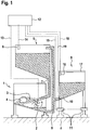
- the blasting system shown is denoted by the reference numeral 1 generally a blasting device in which a blasting medium acceleration device 2, for. B. a turbine for accelerating abrasive 3 is added to a surface of a workpiece 4 schematically indicated here.
- the reference number 5 generally denotes a main bunker which is arranged upstream of the blasting device 1 with respect to a conveying direction of the blasting agent 3.
- a level measuring device 6 is provided in the main bunker 5.
- the reference numeral 7 designates a first slide which can be opened and closed as required in order to provide blasting agent 3.
- the reference number 8 denotes a return device running from the blasting device 1 to the main bunker 5, by means of which the blasting medium 3 is returned to the main bunker 5 after a wind sifting (not shown here).
- the return device 8 comprises a return line in which, for example, a screw conveyor (not shown here) and / or a bucket conveyor (not shown here) are accommodated.
- a preliminary bunker Upstream of the main bunker 5 there is provided a preliminary bunker, generally designated by the reference number 9, which is provided with a second slide 10.
- the second slide 10 can optionally be opened and closed so that blasting media 3 can be fed from the preliminary bunker 9 to the main bunker 5, in particular via the return device 8, at intervals.
- the subsequent metering of the blasting agent 3 at intervals can take place automatically as a function of a fill level in the main bunker 5.
- the pre-bunker 9 is supported against a subsurface U via pressure measurement cells 11.
- a data processing device is indicated schematically with the reference number 12.
- the data processing device 12 is connected to the blasting agent acceleration device 2 via a first signal line 13, to the filling level measuring device 6 via a second signal line 14 and to the pressure measurement cells 11 via a third signal line 15.
- Reference numeral 16 denotes a switch with which an open or closed state of the cover 17 of the preliminary bunker 9 is detected.
- the switch 16 is connected to the data processing device 12 via a fourth signal line 18.
- the reference numeral 19 denotes a fifth signal line via which signals or data can be transmitted from the controller 12 to the second slide 10 for closing and opening the same.
- Signals or data which correspond to the current consumption of the blasting agent acceleration device 2 are supplied via the first signal line 13. Signals or data that correspond to the fill level of the blasting agent 3 in the main bunker 5 are transmitted via the second signal line 14. Signals or data that correspond to the weight of the preliminary bunker 9 are transmitted via the third signal line 15. Signals or data which indicate whether the cover 17 is open or closed are transmitted via the fourth signal line 18.
- the total power consumption also includes, in particular, the power required to transport the blasting agent 3 by means of the return device.
- the return device 8 comprises, for example, a bucket elevator.
- the function of the device or the method that can be carried out with it is as follows: With the abrasive accelerator 2, abrasive 3 is thrown against the surface of a workpiece 4, whereby the surface is removed. As a result, a fine grain fraction forms in the blasting agent 3, which is unsuitable for blasting the surface of the workpiece 4. The fine grain fraction is removed from the blasting agent 3 by means of a conventional air separation.
- the appropriately prepared blasting agent 3 is returned from the blasting device 1 through the return device 8 to the main bunker 5. In the main bunker 5, the level of blasting media 3 is continuously measured by means of the level measuring device 6. The corresponding measured values are fed to the data processing device 12 via the second signal line 14.
- the second slide 10 on the pre-bunker 9 is opened for a predetermined period of time.
- new blasting media 3 is fed to the main bunker 5 at intervals via the return device 8.
- a first weight of the pre-bunker 9 together with the blasting agent 3 received therein is measured by means of the pressure measuring cells 11.
- the first weight is stored in the data processing device 12.
- a second weight of the pre-bunker 9 together with the blasting agent 3 still remaining therein is measured.
- a third weight is obtained from the difference between the first weight and the second weight, which corresponds to the amount of additional blasting agent 3.
- the weight of subsequently dosed blasting agent 3 or the amount resulting therefrom is recorded over time by means of the data processing device 12 (see FIG Fig. 2 ). Furthermore, the power consumption of the blasting agent acceleration device 2 is recorded over time with the data processing device 12 through the first signal line 13 (see FIG Fig. 3 ).
- a limit value is expediently specified with regard to the current consumption. If the power consumption is above the limit value, the abrasive accelerator 2 is properly loaded with abrasive 3. Above the limit value, the blasting agent acceleration device 2 is in "blasting mode". If the current consumption falls below the limit value, this indicates improper operation of the blasting agent acceleration device 2 or its idling. Improper operation can be caused, for example, by worn turbine blades, bearing damage or the like. Idling can be caused, for example, by an interruption in delivery in the return device 8.
- an alarm signal is advantageously triggered by means of the data processing device 12.
- the power consumption of the blasting agent acceleration device 2 is recorded over time by means of the data processing device 12.
- the data processing device 12 Advantageously, only those are used to determine the actual radiation duration Time intervals added up at which the current consumption is above the limit value.
- Fig. 4 shows the average abrasive consumption over time.
- the average blasting media consumption for the specific time 08:30 am is 20 kg / h.
- the grain size distribution of the blasting agent 3 a pulse transmitted from the blasting agent acceleration device 2 to the blasting agent 3, etc. can be varied. Furthermore, depending on the workpiece 4 to be machined, previously determined optimal blasting powers can be set.
- the switch 16 is used to monitor whether the cover 17 is open or closed.
- the second slide 10 is automatically locked, that is, as long as the cover 17 is open, no additional dosing of abrasive 3 from the pre-bunker 9 into the return device 8 takes place subsequently metered blasting agent 3 is falsified.
- the switch 16 or the lid 17 is closed, however, automatic replenishing of blasting agent 3 is possible - as described above.
Landscapes
- Engineering & Computer Science (AREA)
- Mechanical Engineering (AREA)
- Finish Polishing, Edge Sharpening, And Grinding By Specific Grinding Devices (AREA)
- Application Of Or Painting With Fluid Materials (AREA)
- Physical Or Chemical Processes And Apparatus (AREA)
- Filling Or Emptying Of Bunkers, Hoppers, And Tanks (AREA)
Applications Claiming Priority (4)
| Application Number | Priority Date | Filing Date | Title |
|---|---|---|---|
| DE102016219215 | 2016-10-04 | ||
| DE102016223190.1A DE102016223190B3 (de) | 2016-10-04 | 2016-11-23 | Verfahren und Vorrichtung zur Ermittlung eines Betriebszustands einer Strahlanlage |
| EP17772684.1A EP3523091B1 (de) | 2016-10-04 | 2017-09-21 | Verfahren und vorrichtung zur ermittlung eines betriebszustands einer strahlanlage |
| PCT/EP2017/073843 WO2018065220A1 (de) | 2016-10-04 | 2017-09-21 | Verfahren und vorrichtung zur ermittlung eines betriebszustands einer strahlanlage |
Related Parent Applications (2)
| Application Number | Title | Priority Date | Filing Date |
|---|---|---|---|
| EP17772684.1A Division EP3523091B1 (de) | 2016-10-04 | 2017-09-21 | Verfahren und vorrichtung zur ermittlung eines betriebszustands einer strahlanlage |
| EP17772684.1A Division-Into EP3523091B1 (de) | 2016-10-04 | 2017-09-21 | Verfahren und vorrichtung zur ermittlung eines betriebszustands einer strahlanlage |
Publications (1)
| Publication Number | Publication Date |
|---|---|
| EP3792002A1 true EP3792002A1 (de) | 2021-03-17 |
Family
ID=59980817
Family Applications (2)
| Application Number | Title | Priority Date | Filing Date |
|---|---|---|---|
| EP20200330.7A Withdrawn EP3792002A1 (de) | 2016-10-04 | 2017-09-21 | Vorrichtung zur ermittlung eines betriebszustands einer strahlanlage |
| EP17772684.1A Active EP3523091B1 (de) | 2016-10-04 | 2017-09-21 | Verfahren und vorrichtung zur ermittlung eines betriebszustands einer strahlanlage |
Family Applications After (1)
| Application Number | Title | Priority Date | Filing Date |
|---|---|---|---|
| EP17772684.1A Active EP3523091B1 (de) | 2016-10-04 | 2017-09-21 | Verfahren und vorrichtung zur ermittlung eines betriebszustands einer strahlanlage |
Country Status (6)
| Country | Link |
|---|---|
| EP (2) | EP3792002A1 (pl) |
| DE (2) | DE102016223190B3 (pl) |
| DK (1) | DK3523091T3 (pl) |
| ES (1) | ES2913060T3 (pl) |
| PL (1) | PL3523091T3 (pl) |
| WO (1) | WO2018065220A1 (pl) |
Families Citing this family (5)
| Publication number | Priority date | Publication date | Assignee | Title |
|---|---|---|---|---|
| DE102021101036A1 (de) | 2021-01-19 | 2022-07-21 | Eisenwerk Würth GmbH | Vorrichtung zum Behandeln einer Oberfläche eines Werkstücks mit einem Strahlmittel |
| DE102021115034A1 (de) * | 2021-06-10 | 2022-12-15 | Rösler Holding Gmbh | Verfahren zum Betrieb einer Strahlanlage |
| DE102021132554A1 (de) * | 2021-12-09 | 2023-06-15 | Rösler Holding Gmbh | System und Verfahren zur Ermittlung eines Verschleißzustandes eines Schleuderrads |
| JP2024095867A (ja) * | 2022-12-29 | 2024-07-11 | 新東工業株式会社 | ショットブラスト装置、制御方法、制御プログラム |
| CN119328678A (zh) * | 2024-11-25 | 2025-01-21 | 西安理工大学 | 包含加工过程监测的喷丸加工装置及方法 |
Citations (10)
| Publication number | Priority date | Publication date | Assignee | Title |
|---|---|---|---|---|
| DE3131002A1 (de) | 1981-08-05 | 1983-03-24 | Sergiu Dipl.-Ing. 8000 München Caftanat | Automatische druckstrahlanlage mit genauer und reproduzierbarer dosierung des strahlmittels und kontinuierlichem betrieb |
| US4862649A (en) * | 1986-08-28 | 1989-09-05 | Ltv Aerospace & Defense Co. | Material transfer system |
| EP0456502A2 (en) | 1990-05-10 | 1991-11-13 | Colas S.A. | Applicator for applying a surface treatment |
| JPH06143147A (ja) * | 1992-11-04 | 1994-05-24 | Inax Corp | ショットブラスト装置の制御方法 |
| US5975985A (en) * | 1996-10-31 | 1999-11-02 | Phillips Technologies, Inc. | Automated surface treatment apparatus having current monitoring means |
| WO2003055644A1 (en) * | 2001-12-27 | 2003-07-10 | Politecnico Di Milano | System for regulating the abrasive mass flow rate in a waterjet cutting system |
| DE10332713B3 (de) | 2003-07-18 | 2004-07-15 | Schlick Roto-Jet Maschinenbau Gmbh | Strahlintensitätsmessvorrichtung für Oberflächenbehandlungseinrichtungen |
| WO2014040125A1 (en) | 2012-09-11 | 2014-03-20 | Techni Waterjet Pty Ltd | Pump for abrasives |
| DE202016100542U1 (de) | 2016-02-03 | 2016-02-16 | Wiwox Gmbh Surface Systems | System zur zeitgerechten Bereitstellung von Behandlungsmittel |
| DE102015000632A1 (de) | 2015-01-22 | 2016-07-28 | Sentenso Gmbh | Regelung des Strahlmitteldurchsatzes einer Strahlanlage |
Family Cites Families (5)
| Publication number | Priority date | Publication date | Assignee | Title |
|---|---|---|---|---|
| CH674096A5 (pl) * | 1988-01-19 | 1990-04-30 | Lonza Ag | |
| IT1238882B (it) * | 1990-02-28 | 1993-09-04 | Giorgini Maggi Srl | Procedimento per il lavaggio ed il controllo della composizione di torbide abrasive usate nel taglio di graniti e pietre similari e relativa apparecchiatura. |
| US5854744A (en) * | 1996-06-25 | 1998-12-29 | Ingersoll-Rand Company | Adaptive process control system |
| US5810045A (en) * | 1996-12-16 | 1998-09-22 | Bulldog Technologies U.S.A., Inc. | Valve device for introducing particulate materials into a high pressure air stream |
| US9058707B2 (en) * | 2009-02-17 | 2015-06-16 | Ronald C. Benson | System and method for managing and maintaining abrasive blasting machines |
-
2016
- 2016-11-23 DE DE102016223190.1A patent/DE102016223190B3/de active Active
-
2017
- 2017-09-15 DE DE202017105608.2U patent/DE202017105608U1/de active Active
- 2017-09-21 ES ES17772684T patent/ES2913060T3/es active Active
- 2017-09-21 EP EP20200330.7A patent/EP3792002A1/de not_active Withdrawn
- 2017-09-21 DK DK17772684.1T patent/DK3523091T3/da active
- 2017-09-21 EP EP17772684.1A patent/EP3523091B1/de active Active
- 2017-09-21 WO PCT/EP2017/073843 patent/WO2018065220A1/de not_active Ceased
- 2017-09-21 PL PL17772684T patent/PL3523091T3/pl unknown
Patent Citations (10)
| Publication number | Priority date | Publication date | Assignee | Title |
|---|---|---|---|---|
| DE3131002A1 (de) | 1981-08-05 | 1983-03-24 | Sergiu Dipl.-Ing. 8000 München Caftanat | Automatische druckstrahlanlage mit genauer und reproduzierbarer dosierung des strahlmittels und kontinuierlichem betrieb |
| US4862649A (en) * | 1986-08-28 | 1989-09-05 | Ltv Aerospace & Defense Co. | Material transfer system |
| EP0456502A2 (en) | 1990-05-10 | 1991-11-13 | Colas S.A. | Applicator for applying a surface treatment |
| JPH06143147A (ja) * | 1992-11-04 | 1994-05-24 | Inax Corp | ショットブラスト装置の制御方法 |
| US5975985A (en) * | 1996-10-31 | 1999-11-02 | Phillips Technologies, Inc. | Automated surface treatment apparatus having current monitoring means |
| WO2003055644A1 (en) * | 2001-12-27 | 2003-07-10 | Politecnico Di Milano | System for regulating the abrasive mass flow rate in a waterjet cutting system |
| DE10332713B3 (de) | 2003-07-18 | 2004-07-15 | Schlick Roto-Jet Maschinenbau Gmbh | Strahlintensitätsmessvorrichtung für Oberflächenbehandlungseinrichtungen |
| WO2014040125A1 (en) | 2012-09-11 | 2014-03-20 | Techni Waterjet Pty Ltd | Pump for abrasives |
| DE102015000632A1 (de) | 2015-01-22 | 2016-07-28 | Sentenso Gmbh | Regelung des Strahlmitteldurchsatzes einer Strahlanlage |
| DE202016100542U1 (de) | 2016-02-03 | 2016-02-16 | Wiwox Gmbh Surface Systems | System zur zeitgerechten Bereitstellung von Behandlungsmittel |
Also Published As
| Publication number | Publication date |
|---|---|
| DK3523091T3 (da) | 2022-04-19 |
| DE102016223190B3 (de) | 2017-10-19 |
| DE202017105608U1 (de) | 2017-11-15 |
| EP3523091B1 (de) | 2022-02-23 |
| ES2913060T3 (es) | 2022-05-31 |
| WO2018065220A1 (de) | 2018-04-12 |
| PL3523091T3 (pl) | 2022-06-20 |
| EP3523091A1 (de) | 2019-08-14 |
Similar Documents
| Publication | Publication Date | Title |
|---|---|---|
| EP3523091B1 (de) | Verfahren und vorrichtung zur ermittlung eines betriebszustands einer strahlanlage | |
| EP0061756B1 (de) | Vorrichtung zur Oberflächenbehandlung von Bauwerken und Schiffen | |
| DE60313833T2 (de) | Bodenverarbeitungsmaschine | |
| DE3912791A1 (de) | Schrotstrahlsystem und verfahren zum schrotstrahlen | |
| EP4201528A1 (de) | Verfahren zur einstellung eines betriebszustands zumindest einer mobilen mineral-bearbeitungsanlage | |
| DE112019000532T5 (de) | Schleudermaterial und Verfahren zur Strahlbearbeitung | |
| EP0940189A2 (de) | Pulverbeschichtungsanlage und -verfahren zum Speisen und Mischen von Pulver in einer Beschichtungsanlage | |
| DE102016111291A1 (de) | Vorrichtung und Verfahren zur Wärmebehandlung von mineralischem Gut | |
| DE2622603A1 (de) | Verfahren zur herstellung von metallpulver | |
| DE102009060454B4 (de) | Vorrichtung zur Aerosolerzeugung | |
| EP1430998A1 (de) | Vorrichtung zur Oberflächenbearbeitung eines Werkstücks, sowie die Verwendung der Vorrichtung zum Strahlen von Bohrungswandungen | |
| EP4029649B1 (de) | Vorrichtung zum behandeln einer oberfläche eines werkstücks mit einem strahlmittel | |
| DE102017116241A1 (de) | Vorrichtung zur Behandlung von Schottersteinen für Gleisanlagen sowie ein Verfahren zur Anwendung bei der Vorrichtung | |
| DE102017205682A1 (de) | Vorrichtung und Verfahren zum Hochdruck-Fluidstrahlschneiden | |
| DE3241459C1 (de) | Verfahren und Vorrichtung zum Abrunden koerniger Feststoffpartikel | |
| DE3033575A1 (de) | Verfahren und vorrichtung zur leistungsregelung einer muehle | |
| DE102018209858A1 (de) | Vorrichtung zur mengendosierten Sprühstoffabgabe in Form eines Sprays | |
| DE19727348A1 (de) | Verfahren zur Regelung von Stein-Zerkleinerungsanlagen unter Einsatz von Prallbrechern o. dgl. | |
| DE4422769A1 (de) | Hochdruck-Wasserschneidvorrichtung | |
| DE10031883C2 (de) | Verfahren und Anordnung zur variablen Regelung der Zufuhrmenge des Materials schwankender Beschaffenheit, das einer aus mehreren Aggregaten bestehenden Anlage, insbesondere einer Sand- und Kiesaufbereitungsanlage, zugeführt wird | |
| DE2625426C2 (de) | Vorrichtung mit einem Detektor zur Steuerung des Grobgutaustrages von Kaskadenluftsichtern im Strahlmittel-Reinigungskreislauf von Strahlmaschinen | |
| DE102023209382A1 (de) | Spritzverfahren für ein Spritzmedium und Spritzsystem für ein Spritzmedium | |
| DE1615089A1 (de) | Verfahren und Einrichtung zur Regelung der Generatorzuendspannung in Abhaengigkeit vom Bearbeitungsspalt bei Elektroerosionsmaschinen | |
| AT220753B (de) | Verfahren und Vorrichtung zum automatischen Ascheabzug aus Feuerungen und Gaserzeugern | |
| DE102015223155A1 (de) | Messung der Strahlkraft in einer Feststoffstrahlanlage |
Legal Events
| Date | Code | Title | Description |
|---|---|---|---|
| PUAI | Public reference made under article 153(3) epc to a published international application that has entered the european phase |
Free format text: ORIGINAL CODE: 0009012 |
|
| STAA | Information on the status of an ep patent application or granted ep patent |
Free format text: STATUS: THE APPLICATION HAS BEEN PUBLISHED |
|
| AC | Divisional application: reference to earlier application |
Ref document number: 3523091 Country of ref document: EP Kind code of ref document: P |
|
| AK | Designated contracting states |
Kind code of ref document: A1 Designated state(s): AL AT BE BG CH CY CZ DE DK EE ES FI FR GB GR HR HU IE IS IT LI LT LU LV MC MK MT NL NO PL PT RO RS SE SI SK SM TR |
|
| STAA | Information on the status of an ep patent application or granted ep patent |
Free format text: STATUS: REQUEST FOR EXAMINATION WAS MADE |
|
| STAA | Information on the status of an ep patent application or granted ep patent |
Free format text: STATUS: EXAMINATION IS IN PROGRESS |
|
| 17P | Request for examination filed |
Effective date: 20210915 |
|
| RBV | Designated contracting states (corrected) |
Designated state(s): AL AT BE BG CH CY CZ DE DK EE ES FI FR GB GR HR HU IE IS IT LI LT LU LV MC MK MT NL NO PL PT RO RS SE SI SK SM TR |
|
| 17Q | First examination report despatched |
Effective date: 20211004 |
|
| RIN1 | Information on inventor provided before grant (corrected) |
Inventor name: VIANDEN, JOACHIM Inventor name: WINKLER, TIMO |
|
| STAA | Information on the status of an ep patent application or granted ep patent |
Free format text: STATUS: THE APPLICATION HAS BEEN WITHDRAWN |
|
| 18W | Application withdrawn |
Effective date: 20230918 |