EP3782500A1 - Spangenelement für accessoire, spange für accessoire und accessoire - Google Patents
Spangenelement für accessoire, spange für accessoire und accessoire Download PDFInfo
- Publication number
- EP3782500A1 EP3782500A1 EP19869076.0A EP19869076A EP3782500A1 EP 3782500 A1 EP3782500 A1 EP 3782500A1 EP 19869076 A EP19869076 A EP 19869076A EP 3782500 A1 EP3782500 A1 EP 3782500A1
- Authority
- EP
- European Patent Office
- Prior art keywords
- base
- movable
- fastening member
- coupling
- portions
- Prior art date
- Legal status (The legal status is an assumption and is not a legal conclusion. Google has not performed a legal analysis and makes no representation as to the accuracy of the status listed.)
- Granted
Links
Images


Classifications
-
- A—HUMAN NECESSITIES
- A44—HABERDASHERY; JEWELLERY
- A44B—BUTTONS, PINS, BUCKLES, SLIDE FASTENERS, OR THE LIKE
- A44B13/00—Hook or eye fasteners
- A44B13/0029—Hook or eye fasteners characterised by their way of fastening to the support
-
- A—HUMAN NECESSITIES
- A44—HABERDASHERY; JEWELLERY
- A44C—PERSONAL ADORNMENTS, e.g. JEWELLERY; COINS
- A44C5/00—Bracelets; Wrist-watch straps; Fastenings for bracelets or wrist-watch straps
- A44C5/18—Fasteners for straps, chains or the like
- A44C5/20—Fasteners for straps, chains or the like for open straps, chains or the like
- A44C5/2019—Hooks
- A44C5/2033—Hooks provided with pivoting closure means
Definitions
- the related-art fastening implements are poor in operability. Specifically, for example, in putting on the accessory, or in taking off the accessory from the body, a fine operation with fingertips may be required to open and close the fastening member.
- the following fine coupling operation needs to be performed.
- this coupling operation first, one of the fastening members is opened by a fine operation to form a small opening portion (gap) . In this state, another one of the fastening members is inserted into this small opening portion in alignment therewith.
- the fine operation may need to be performed only with one hand.
- the fine operation may need to be performed behind the neck without direct looking.
- the related-art fastening implements have inconvenienced the user who puts on the accessories with the related-art fastening implements.
- the linear member of the accessory has a design feature, depending, for example, on structure of the fastening implement, the continuous design feature of the linear member may be impaired. As a result, an aesthetic appearance of the accessory may be impaired.
- a first coupling portion 151a of the first member 151 needs to be moved to a vicinity of support portions 152a by passing an entirety of a movable-side body portion 152b through the first coupling portion 151a.
- a distal end portion of the movable-side body portion 152b is curved.
- a protruding piece portion 152c which is formed to protrude from the movable-side body portion 152b so as to facilitate an operation to turn the movable-side body portion 152b, causes a disadvantage peculiar to the buckle-type fastening implement.
- the first coupling portion 151a and the long movable-side body portion 152b or the protruding piece portion 152c of the second member 152 interfere with each other, which is liable to hinder the first coupling portion 151a from being moved to the support portions 152a.
- the ring-like first coupling portion 151a may be enlarged.
- downsizing of the fastening implement 150 in particular, downsizing of the first member 151 is hindered.
- the aesthetic appearance of the accessory may be significantly impaired by the fastening implement 150.
- the clasp member for accessory to be provided according to the present invention includes the following aspect.
- the clasp member for accessory according to the aspect of the present invention is a clasp member for accessory that is separably coupled to a coupling subject portion, and that includes:
- the base-side coupling portion is arranged on one side in a longitudinal direction of the base portion, the one side being opposite to another side on which a connecting part of the base portion is arranged, the connecting part being connected to the part of the accessory, the movable portion includes a movable-side coupling portion, and under a state in which the movable portion is arranged at a closed position where the movable portion closes the fastening member,
- a clasp for accessory according to the aspect of the present invention includes:
- An accessory according to the aspect of the present invention includes the clasp member for accessory according to the aspect of the present invention.
- a direction along force in pulling one end portion and another end portion of a linear member in directions away from each other under a state in which a fastening implement is coupled is defined as a longitudinal direction and a front-and-rear direction of the fastening implement.
- a longitudinal direction and a front-and-rear direction of a fastening member are directions parallel respectively to the longitudinal direction and the front-and-rear direction of the fastening implement.
- the fastening member according to the present invention is separably coupled to a part of an accessory, which does not form the fastening implement, or when the fastening member according to the present invention is separably coupled to a member other than the accessory, the longitudinal direction and the front-and-rear direction of the fastening member correspond to directions along pulling directions at a time when the fastening member according to the present invention and a section on a side to which the fastening member is directly coupled are pulled in directions away from each other.
- the section to which the fastening member is directly coupled refers to a coupling subject portion.
- a direction along a line of intersection of a plane orthogonal to the longitudinal directions and a plane including a turning direction of a movable portion provided to the fastening member is defined as a height direction and an upper-and-lower direction of the fastening implement.
- a height direction and an upper-and-lower direction of the fastening implement are directions along the height direction and the upper-and-lower direction of the fastening implement.
- an upper-and-lower direction in the drawing sheet of FIG. 1 corresponds to the upper-and-lower direction of the fastening implement.
- a direction orthogonal to the longitudinal direction and the height direction of the fastening implement is defined as a width direction and a right-and-left direction of the fastening implement.
- These width direction and right-and-left direction correspond to directions parallel to a rotary shaft of the movable portion of the fastening member.
- a width direction and a right-and-left direction of the fastening member correspond respectively to directions parallel to the width direction and the right-and-left direction of the fastening implement.
- a front-and-back direction of the drawing sheet of FIG. 1 corresponds to the right-and-left direction of the fastening implement.
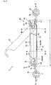
- the accessory is a tennis bracelet.
- the accessory according to the present invention is not limited to the tennis bracelet, and encompasses accessories other than the tennis bracelet.
- the chain member 5 of the tennis bracelet 1 includes a plurality of link portions 6, and coupling members 7 that couple adjacent two of the link portions 6 to each other.
- the coupling members 7 are attached to be swingable relative to the link portions 6.
- the link portions 6 each include a link body portion that is formed into a substantially quadrangular-cylindrical shape or a substantially cylindrical shape, and a gemstone (such as diamond) (not shown) to be fixed to an outer surface portion of the link body portion.
- the chain member 5 according to the first embodiment is one of specific examples of the linear member according to the present invention.
- the linear member may be a flexible member other than the chain member, such as a string member.
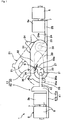
- the full-open position refers to a position where an operating portion 34 described below of the movable portion 31 comes into abutment against a turning stop portion 24 described below of the base portion 21, whereby the first fastening member 20 is most widely opened.
- the full-open position corresponds to a turning limit position on an opening-direction side of the movable portion 31.
- an inner space portion 27 is formed on an inner peripheral side of the base-side coupling portion 26.
- the inner space portion 27 is surrounded by an inner peripheral portion of the base-side coupling portion 26 and an inner peripheral portion of the base-side body portion 22.
- the inner peripheral portion of the base-side coupling portion 26 is formed of a curved inner-peripheral surface of the base-side coupling portion 26.
- the inner space portion 27 is capable of housing a part of a second coupling ring 42 described below of the second fastening member 40.
- a length of the base-side coupling portion 26 according to the first embodiment is set so that a central angle of the curved circular-arc part in the side view of the first fastening member 20 is 135° or more.
- the base-side coupling portion 26 may be formed to have a size in which the central angle of the circular-arc part is 180° or more.
- This base-side coupling portion 26 is formed to have a length that does not reach a position of the lateral cover portions 33 described below of the movable portion 31 under a state in which the first fastening member 20 is closed (refer to FIG. 1 ). In this case, in the side view of FIG. 1 , the distal end portion of the base-side coupling portion 26 does not hide in an inside in the width direction of the lateral cover portions 33.
- a gap G is formed between the distal end of the base-side coupling portion 26 and restriction rim portions 33a described below of the lateral cover portions 33.
- a minimum value of this gap G is set so that the second coupling ring 42 described below of the second fastening member 40 is not allowed to be inserted therethrough.
- the minimum value of the gap G corresponds to a shortest distance between the base-side coupling portion 26 and the restriction rim portions 33a of the lateral cover portions 33.
- the gap G is formed to be smaller than a thickness of the second coupling ring 42 of the second fastening member 40.
- the thickness of the second coupling ring 42 corresponds to a diameter of its circular shape in cross-section orthogonal to a circumferential direction of the second coupling ring 42.
- the central portion of the locking recessed portion 26a which is recessed deepest, is located below an intermediate position between a height position of the lower surface of the base-side body portion 22 and a height position of an outer peripheral surface of the distal end portion of the base-side coupling portion 26.
- the movable portion 31 of the first fastening member 20 includes a movable-side body portion 32 that extends in the front-and-rear direction under the state illustrated in FIG. 1 , in which the movable portion 31 is held at the closed position, and the movable-side coupling portion 35 that extends to be curved into a fish-hook shape or a circular-arc shape from the movable-side body portion 32 under the same state. Further, the movable portion 31 includes the lateral cover portions 33 that are provided on both right-and-left sides of the movable-side body portion 32, and that extend downward from the movable-side body portion 32 toward the base portion 21.
- the movable-side body portion 32 is formed along the front-and-rear direction from a position superimposed on an outer peripheral surface of the base-side coupling portion 26 to a position above the base-side support portion 23.
- the movable-side body portion 32 is arranged at a position away from the base-side body portion 22.
- a dimension in the width direction of the movable-side body portion 32 is equal to or slightly larger than each of the dimension in the width direction of the base-side body portion 22 and the dimension in the width direction of the base-side coupling portion 26.
- the first fastening member 20 is closed to shield the inner space portion 27 of the base portion 21 from the space on the outside in the side view.
- the lateral cover portions 33 on both the right-and-left sides are continuous with the right-and-left lateral surface portions of the movable-side body portion 32, and hence are formed integrally with the movable-side body portion 32.
- the lateral cover portions 33 are each formed into a plate shape that droops downward from the position in FIG. 1 , where the movable-side body portion 32 is arranged, toward the base-side body portion 22. Between the right-and-left lateral cover portions 33, a clearance into which the base-side support portion 23 of the base portion 21 can be inserted is provided.
- the coupling shaft portion 30 On inner wall surfaces of the right-and-left lateral cover portions 33, which face each other, the coupling shaft portion 30 in a columnar shape is provided in a protruding manner in conformity with the bearing recessed portions of the base-side support portion 23.
- the coupling shaft portion 30 is arranged in a region of the rotary coupling portion of the lateral cover portions 33, which is superimposed on the base-side support portion 23 in the side view of the first fastening member 20.
- the right-and-left lateral cover portions 33 cover a part of the inner space portion 27 to be formed in the base portion 21 from lateral sides.
- the lateral cover portions 33 are each formed to have a size to be superimposed on at least a part of the base-side body portion 22 in the side view of the first fastening member 20.
- the lateral cover portions 33 are each formed to have a size in which lower edges of the lateral cover portions 33, which extend straight, and a lower edge of the base-side body portion 22, which extends straight, are superimposed on each other.
- the lateral cover portions 33 include the restriction rim portions 33a that extend downward from the position of the movable-side body portion 32 under the state in which the movable portion 31 is held at the closed position in the side view of the first fastening member 20.
- the restriction rim portions 33a refer to rim portions on a side in the front-and-rear direction of the lateral cover portions 33, which is close to the movable-side coupling portion 35.
- the movable portion 31 includes a space region that is surrounded by the restriction rim portions 33a of the lateral cover portions 33, the movable-side body portion 32, and the movable-side coupling portion 35 in the side view of the first fastening member 20.
- an inner peripheral angle ⁇ 1 to be formed between the restriction rim portions 33a of the lateral cover portions 33 and the lower edge of the movable-side body portion 32 is 90° or less. How high this angle ⁇ 1 is is represented by imaginary lines (two-dot chain lines) in FIG. 1 , which indicate a part corresponding to the movable portion 31.
- the inner peripheral angle ⁇ 1 refers to an angle to be formed between the movable-side body portion 32 and the restriction rim portions 33a in the space region in the side view of the movable portion 31.
- this inner peripheral angle ⁇ 1 may be less than 90°, or may be 89° or less.
- a lower limit value of this inner peripheral angle ⁇ 1 is not particularly limited.
- the restriction rim portions 33a are provided to the lateral cover portions 33, a dimension in the front-and-rear direction of the lower end portion of each of the lateral cover portions 33 is larger than a dimension in the front-and-rear direction of an upper end portion of the same.
- the lateral cover portions 33 according to the first embodiment are each formed to have a size in which the gap G has the minimum value at which the second coupling ring 42 of the second fastening member 40 is not allowed to be inserted therethrough into the base-side coupling portion 26 under the state illustrated in FIG. 1 , in which the first fastening member 20 is closed.
- the movable-side coupling portion 35 extends to be curved into the fish-hook shape or the circular-arc shape from an end portion of the movable-side body portion 32, which is opposite to the end portion on the side where the operating portion 34 is provided, toward the base-side coupling portion 26 thereunder.
- an inner peripheral portion of the movable-side coupling portion 35 is capable of coming into abutment against at least a part of an outer peripheral portion of the base-side coupling portion 26 of the base portion 21.
- the movable-side coupling portion 35 may be formed so that the inner peripheral portion of the movable-side coupling portion 35 is held in surface contact with the outer peripheral portion of the base-side coupling portion 26 of the base portion 21.
- the inner peripheral portion of the movable-side coupling portion 35 is formed of a curved inner-peripheral surface of the movable-side coupling portion 35. In the side view of the first fastening member 20, this inner peripheral portion of the movable-side coupling portion 35 is arranged on a side closer to the coupling shaft portion 30 that serves as a rotary shaft of the movable portion 31 than an outer peripheral portion of the movable-side coupling portion 35 is close.
- the first fastening member may be formed while varying the base-side coupling portion and the movable-side coupling portion in size relative to each other so that, for example, the outer peripheral portion of the movable-side coupling portion can be brought into contact with or face the inner peripheral portion of the base-side coupling portion.
- the locking-subject protruding portion 35a that swells toward an inside relative to the movable-side coupling portion 35 is formed at the distal end portion of the movable-side coupling portion 35.
- This locking-subject protruding portion 35a has a size to be capable of being inserted into the locking recessed portion 26a of the base-side coupling portion 26.
- This locking-subject protruding portion 35a is held by being inserted into the locking recessed portion 26a of the base-side coupling portion 26. With this, when the movable portion 31 is moved to the closed position, the movable-side coupling portion 35 is locked to the base-side coupling portion 26. In this way, the movable portion 31 can be maintained at the closed position.
- the swelling curved surface of the locking-subject protruding portion 35a and a distal end surface of the movable-side coupling portion 35 are formed as surfaces that are smoothly continuous with each other in the side view of the first fastening member 20. With this, the locking-subject protruding portion 35a of the movable-side coupling portion 35 can be smoothly inserted into and removed from the locking recessed portion 26a of the base-side coupling portion 26.
- the movable portion 31 can be locked at the closed position.
- magnetic force to be generated by providing a magnet to an at least one of the movable-side coupling portion 35 and the base-side coupling portion 26 may be utilized to lock the movable-side coupling portion 35 to the base-side coupling portion 26.
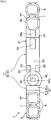
- the other end portion of the chain member 5 is fixed to the second connecting-piece portion 41b by welding such as brazing at a position away from the second connecting-body portion 41a.
- two of the link portions 6 of the chain member 5 are fixed to the second connecting-piece portion 41b of the second connecting portion 41 so that the second fastening member 40 can be easily picked up with fingers.
- the second coupling ring 42 extends along the front-and-rear direction from a substantially central portion in the upper-and-lower direction of a surface of the second connecting-body portion 41a, which is on a side opposite to a side on which the second connecting-piece portion 41b is provided.
- the insertion hole portion 42a is provided through the second coupling ring 42 in the upper-and-lower direction.
- the second coupling ring 42 is formed into a ring shape that exhibits, as viewed from above (refer to FIG. 2 ), a part of a circular shape or a part of an elliptical shape.
- this second coupling ring 42 corresponds to the coupling subject portion to which the first fastening member 20 is coupled.
- the second coupling ring 42 is formed to exhibit the circular shape in the cross-section orthogonal to the circumferential direction, the second coupling ring 42 is not limited thereto.
- the second coupling ring 42 may be formed into other shapes such as a substantially quadrangular shape in the cross-section.
- the second coupling ring 42 may be formed into still other shapes in which the insertion hole portion 42a can be formed, such as a U-shape as viewed from above.
- the insertion hole portion 42a of the second coupling ring 42 is opened to have a size in which both the base-side coupling portion 26 and the movable-side coupling portion 35 of the first fastening member 20 can be inserted through the insertion hole portion 42a itself when the first fastening member 11 and the second fastening member 21 are coupled to each other.
- the protruding piece portion 36 of the first fastening member 20 can be inserted through the insertion hole portion 42a itself together with the base-side coupling portion 26 and the movable-side coupling portion 35.
- the first fastening member 20 coupled to the second fastening member 40 can be moved in a direction indicated by a two-dot-chain-line arrow in FIG. 1 .
- the second coupling ring 42 can be prevented from catching on the first fastening member 20.
- the second coupling ring 42 can be prevented from catching on the protruding piece portion 36 of the first fastening member 20.
- the movable portion 31 can be prevented from being turned in the direction in which the movable portion 31 is opened.
- the second fastening member 40 is prevented from being disengaged from the first fastening member 20.
- weight of the chain member 5 causes the first fastening member 20 and the second fastening member 40 to be pulled in directions away from each other.
- the state in which the second fastening member 40 is temporarily held can be easily and stably maintained.
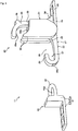
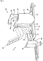
- first fastening member 20 and the second fastening member 40 are separated from each other under the state illustrated in FIG. 1 , in which the first fastening member 20 and the second fastening member 40 are coupled to each other.
- the movable portion 31 of the first fastening member 20 is turned in the direction away from the base-side body portion 22. With this, the first fastening member 20 is opened to uncover the upper side of the insertion-and-removal opening portion 28. This operation of the first fastening member 20 for turning the movable portion 31 can be easily performed with one hand.
- the first fastening member 20 allows the operations to open and close the first fastening member 20 to be easily performed with one hand. With this, the operation to couple the first fastening member 20 and the second fastening member 40 of the fastening implement 11 to each other and the operation to separate these members from each other can be easily and smoothly performed only with one hand.
- the tennis bracelet 1 according to the first embodiment is capable of significantly increasing ease of the operations in opening and closing the first fastening member 20, and ease of the series of operations in coupling and separating the fastening implement 11 to be greater than those, for example, in the cases where the spring-ring type fastening implement and the plug-in type fastening implement in the related art are used.
- the base-side coupling portion 26 and the movable-side coupling portion 35 are inserted through the insertion hole portion 42a of the second fastening member 40 with the inner peripheral portion of the movable-side coupling portion 35 held in contact with the outer peripheral portion of the base-side coupling portion 26.
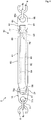
- a chain bracelet 2 according to the second embodiment includes a chain member 8 being the linear member, and a fastening implement 12 that is attached to both one end portion and another end portion of the chain member 8.
- the chain member 8 is formed of a cable chain obtained by coupling a plurality of metal rings 8a to each other.
- the fastening implement 12 according to the second embodiment is made of a metal.
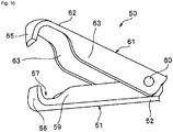
- This fastening implement 12 includes a first fastening member 50 that is attached to the one end portion of the chain member 8, and a second fastening member 70 that is attached to the other end portion of the chain member 8.
- the first fastening member 50 and the second fastening member 70 are separably coupled to each other.
- the first fastening member 50 according to the second embodiment is another example of the fastening member according to the present invention.
- Components of the first fastening member 50 and the second fastening member 70 are each formed by punching or pressing of a metal plate. Note that, in the present invention, manufacturing methods, materials, and the like of the first fastening member 50 and the second fastening member 70 are not particularly limited, and may be selected in accordance with purpose.
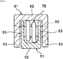
- the first fastening member 50 includes a base portion 51 that extends in the front-and-rear direction, a movable portion 61 that is supported to be capable of turning relative to the base portion 51 by a coupling shaft portion 60, and the torsional spring 75 that biases the movable portion 61.
- the base portion 51 is connected to the chain member 8.
- the movable portion 61 is turned to open and close the first fastening member 50.
- the movable portion 61 is capable of turning relative to the base portion 51 about the coupling shaft portion 60 along the width direction. As illustrated in FIG.
- the movable portion 61 is capable of turning in a range from a closed position where a movable-side coupling portion 65 of the movable portion 61 comes into abutment against a base-side coupling portion 56 of the base portion 51 to a full-open position where an operating portion 64 of the movable portion 61 comes into abutment against a turning stop portion 54 of the base portion 51.
- the coupling shaft portion 60 is formed of a columnar member independent of the base portion 51 and the movable portion 61.
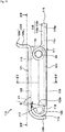
- the base-side body portion 52 is formed into a thin plate shape that extends in the front-and-rear direction. Further, a dimension in the width direction of the base-side body portion 52 is uniform all over the front-and-rear direction (refer to FIG. 6 ) .
- the right-and-left base-side wall portions 59 are formed on an upper surface of the base-side body portion 52 along the front-and-rear direction. A space portion is formed between the right-and-left base-side wall portions 59.
- the base-side body portion 52 and the right-and-left base-side wall portions 59 exhibit a substantially U-shape in cross section orthogonal to the front-and-rear direction (refer to FIG. 7 ). With this, strength of the base portion 51 can be properly secured, and at the same time, weight and material cost of the base portion 51 can be reduced.
- the upper surface and the lower surface of the base-side body portion 52 are surfaces facing each other in the upper-and-lower direction.
- the upper surface of the base-side body portion 52 refers to a surface oriented to a side of the upper direction
- the lower surface of the base-side body portion 52 refers to a surface oriented to a side of the lower direction.
- the right-and-left base-side wall portions 59 each include a continuous wall portion 59a that is formed continuously along the front-and-rear direction in a uniform height dimension, and an inclined wall portion 59b that is arranged at an end portion on a side where the base-side coupling portion 56 is arranged and that is gradually reduced in height dimension toward the base-side coupling portion 56.
- the height dimension of each of the base-side wall portions 59 refers to a dimension in the upper-and-lower direction from the upper surface of the base-side body portion 52 to an upper end surface of each of the base-side wall portions 59.
- the height dimension of each of the continuous wall portions 59a is 25% or more and 75% or less of a height dimension from the lower surface of the base-side body portion 52 to an upper surface of a movable-side body portion 62 described below of the movable portion 61 in the first fastening member 50 in the closed state.
- the relationships between the height dimensions are not particularly limited, and the height dimension may be set, for example, to 40% or more and 60% or less.
- a second coupling portion 72 described below of the second fastening member 70 can be easily guided toward an inner peripheral portion of the base-side coupling portion 56.
- the right-and-left base-side support portions 53 refer to parts each including an upper end portion that exhibits a circular-arc shape in the side view of the first fastening member 50.
- the base-side support portions 53 are provided parallel to the right-and-left base-side wall portions 59 at the end portion on the side in the front-and-rear direction of the base-side body portion 52, where the first chain-connecting portion 55 is provided.
- the base-side body portion 52 and the and the right-and-left base-side support portions 53 exhibit a substantially U-shape in cross-section orthogonal to the front-and-rear direction (refer to FIG. 8 ).
- a coil portion 76 described below of the torsional spring 75 is inserted between the right-and-left base-side support portions 53.
- a height dimension of each of the base-side support portions 53 is larger than the height dimension of each of the continuous wall portions 59a of the base-side wall portions 59.
- the height dimension of each of the base-side support portions 53 refers to a dimension in the upper-and-lower direction from the upper surface of the base-side body portion 52 to a corresponding one of the upper end portions of the base-side support portions 53 each exhibiting the circular-arc shape in the side view.
- a thickness of each of the right-and-left base-side support portions 53 is substantially the same as a thickness of a corresponding one of the base-side wall portions 59.
- each of the base-side support portions 53 and the thickness of each of the base-side wall portions 59 each refer to an interval between its inner wall surface and its outer wall surface.
- Attachment hole portions are formed in the right-and-left direction through the base-side support portions 53 on both right-and-left sides.
- the coupling shaft portion 60 is attached by being inserted into the right-and-left attachment hole portions.
- the turning stop portion 54 of the base portion 51 extends in the front-and-rear direction continuously from the base-side body portion 52.
- a size of the torsional spring 75 may be set to be different from that illustrated in FIG. 5 so that the operating portion 64 is not directly brought into abutment against the turning stop portion 54.
- a part of the torsional spring 75 may be inserted between the turning stop portion 54 and the operating portion 64 so that the operating portion 64 is indirectly brought into abutment against the turning stop portion 54.
- This turning stop portion 54 includes a gradually expanded portion in which a dimension in the width direction is gradually increased to a side away from the base-side body portion 52, and a wide portion that extends continuously from the gradually expanded portion.
- a dimension in the width direction of the wide portion is uniform all over an entirety in the front-and-rear direction of the wide portion.
- the first chain-connecting portion 55 extends in the front-and-rear direction from the turning stop portion 54 continuously and in a thin plate shape.
- a connection hole portion 55a is drilled in the upper-and-lower direction through the first chain-connecting portion 55.
- the connection hole portion 55a exhibits a circular shape in the plan view of the first fastening member 50.
- One of the metal rings 8a which is arranged at the one end portion of the chain member 8, is inserted through the connection hole portion 55a. With this, the chain member 8 and the first chain-connecting portion 55 are connected to each other.
- a configuration of the first chain-connecting portion 55 and means for establishing the connection to the chain member 8 are not particularly limited.
- the base-side coupling portion 56 is formed continuously from an end portion of the base-side body portion 52, which is on a side away from the first chain-connecting portion 55.
- the base-side coupling portion 56 is formed to be curved upward into the fish-hook shape or the circular-arc shape from the end portion of the base-side body portion 52.
- an inner space portion 57 is formed on an inner peripheral side of the base-side coupling portion 56.
- a thickness and a dimension in the width direction of the base-side coupling portion 56 are substantially the same as a thickness and the dimension in the width direction of the base-side body portion 52, respectively.
- the inner space portion 57 of the first fastening member 50 is provided on the inner peripheral side of the base-side coupling portion 56. This inner space portion 57 is arranged on a lower side in the upper-and-lower direction relative to an opening position along the front-and-rear direction of the insertion-and-removal opening portion.
- the inner space portion 57 and the insertion-and-removal opening portion communicate with each other.
- the insertion-and-removal opening portion is uncovered upward as an insertion port into which the second coupling portion 72 of the second fastening member 70 is inserted, or as a removal port through which the second coupling portion 72 is removed. With this, a space on an outside of the first fastening member 20 and the insertion-and-removal opening portion of the first fastening member 50 communicate with each other.
- the movable portion 61 includes the movable-side body portion 62 that extends in the front-and-rear direction under the state in which the movable portion 61 is held at the closed position, and the right-and-left lateral cover portions 63 that are provided on both right-and-left sides of the movable-side body portion 62 and that extend from the movable-side body portion 62 toward the base portion 51.
- the operating portion 64 is provided to extend in a direction bent obliquely upward from the movable-side body portion 62.
- the movable-side coupling portion 65 has a uniform thickness.
- the distal end portion of the movable-side coupling portion 65 includes a part where its dimension in the width direction is gradually reduced toward the distal end portion. With this, the movable-side coupling portion 65 is easily inserted into an insertion hole portion 72a of the second fastening member 70.
- a second connecting-hole portion 71a is drilled in the upper-and-lower direction through the second connecting portion 71 of the second fastening member 70.
- the second connecting-hole portion 71a exhibits a circular shape in the plan view of the second fastening member 70.
- Another one of the metal rings 8a, which is arranged at the other end of the chain member 8, is inserted through the second connecting-hole portion 71a. With this, the chain member 8 and the second connecting portion 71 are connected to each other.
- the second coupling portion 72 corresponds to the coupling subject portion to which the first fastening member 50 is coupled.
- the insertion hole portion 72a is drilled in the upper-and-lower direction through the second coupling portion 72.
- the insertion hole portion 72a exhibits a circular shape in the plan view of the second fastening member 70.
- the insertion hole portion 72a is opened to have a size in which the base-side coupling portion 56 and the movable-side coupling portion 65 of the first fastening member 50 can be inserted at once through the insertion hole portion 72a itself.
- the operating portion 64 of the movable portion 61 and the base portion 51 are pinched with fingers from above and below. Then, the operating portion 64 is pushed with the fingers in a direction toward the turning stop portion 54. With this, the movable portion 61 is easily turned clockwise in FIG. 5 about the coupling shaft portion 60 against the biasing force of the torsional spring 75.
- the base-side coupling portion 56 and the movable-side coupling portion 65 are inserted through the insertion hole portion 72a of the second fastening member 70 with the inner peripheral portion of the movable-side coupling portion 65 held in contact with the outer peripheral portion of the base-side coupling portion 56.
- tensile strength that the fastening implement 12 exhibits, for example, under a state in which the first fastening member 50 and the second fastening member 70 are pulled in directions away from each other can be increased.
- the state in which the first fastening member 50 is closed can be maintained.
- temporal deformation and metal fatigue of the base-side coupling portion 56 of the base portion 51 and the movable-side coupling portion 65 of the movable portion 61 can be prevented.
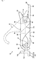
- the base portion 81 includes a plate-like base-side body portion 82 that extends in the front-and-rear direction, base-side wall portions 89 and base-side support portions 83 that extend upward from lateral edge portions on both sides in the right-and-left direction of the base-side body portion 82, and the base-side coupling portion 86 that extends to be curved into a fish-hook shape or a circular-arc shape from the base-side body portion 82.
- the base portion 81 includes the turning stop portion 84 that extends from the base-side body portion 82, and a first chain-connecting portion 85 that extends further from the turning stop portion 84.
- a thickness of the base-side body portion 82 is uniform all over the front-and-rear direction.
- the base-side body portion 82 includes a wide portion in which a dimension in the width direction is uniform, and a gradually tapered portion in which the dimension in the width direction is gradually reduced toward the base-side coupling portion 86 (refer to FIG. 12 ).
- the base-side wall portions 89 on both right-and-left sides are provided as right-and-left lateral edge portions of the wide portion of the base-side body portion 82 along the front-and-rear direction.
- a space portion is formed between the right-and-left base-side wall portions 89.
- the right-and-left lateral cover portions 93 extend downward from right-and-left lateral edge portions of the wide portion of the movable-side body portion 92.
- a space portion is provided between the right-and-left lateral cover portions 93.
- An interval in the width direction in this space portion is larger than an interval between outer wall surfaces of the right-and-left base-side wall portions 89 of the base portion 81.
- the right-and-left lateral cover portions 93 are formed to include at least regions to be superimposed on the base-side support portions 83 in the side view of the first fastening member 80. In these regions to be superimposed on the base-side support portions 83, the attachment hole portions that allow the coupling shaft portion 60 to be attached are formed.
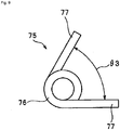
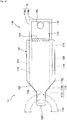
- the second fastening member 100 includes a second connecting portion 101 to which the other end portion of the chain member is coupled by being fixed, and a second coupling ring 102 that is formed integrally with the second connecting portion 101.
- the second connecting portion 101 includes a second connecting-body portion 101a having a height dimension corresponding to that of the first fastening member 80, and a second connecting-piece portion 101b that extends from a lower end portion of the second connecting-body portion 101a toward one side in the front-and-rear direction.
- a distal end portion of the second connecting-piece portion 101b has a shape conforming to a shape of the other end portion of the chain member.
- the base-side body portion 112 includes a wide portion 112a in which a dimension in the width direction is uniform, a gradually tapered portion 112b in which the dimension in the width direction is gradually reduced from the wide portion 112a toward the base-side coupling portion 116, and a narrow portion 112c in which the dimension in the width direction is uniform and smaller than that in the wide portion 112a (refer to FIG. 14 ).
- the base-side body portion 112 can be formed to have an appropriate thickness that allows the base-side body portion 112 to be easily held with fingers.
- the base-side coupling portion 116 is easily inserted through the second fastening member 130.
- the inner peripheral angle ⁇ 1 is set similar to the inner peripheral angle ⁇ 1 described in the first embodiment.
- the inner peripheral angle ⁇ 1 may be less than 90° less, or may be 89° or less.
- a dimension in the front-and-rear direction of the lower edge portion of each of the lateral cover portions 123 is larger than a dimension in the front-and-rear direction of an upper edge portion of the same.
- the fastening member according to the present invention may be used as that of an at least one of a first fastening implement of a first accessory and a second fastening implement of a second accessory so that the first fastening implement and the second fastening implement are coupled to each other. Also in this case, by applying the fastening member according to the present invention, design features of the accessories are not impaired.
Applications Claiming Priority (3)
| Application Number | Priority Date | Filing Date | Title |
|---|---|---|---|
| JP2018188060 | 2018-10-03 | ||
| JP2019113302 | 2019-06-19 | ||
| PCT/JP2019/026859 WO2020070939A1 (ja) | 2018-10-03 | 2019-07-05 | 装身具用留め部材、装身具用留め具、及び装身具 |
Publications (3)
| Publication Number | Publication Date |
|---|---|
| EP3782500A1 true EP3782500A1 (de) | 2021-02-24 |
| EP3782500A4 EP3782500A4 (de) | 2022-02-16 |
| EP3782500B1 EP3782500B1 (de) | 2026-03-18 |
Family
ID=70055357
Family Applications (1)
| Application Number | Title | Priority Date | Filing Date |
|---|---|---|---|
| EP19869076.0A Active EP3782500B1 (de) | 2018-10-03 | 2019-07-05 | Spangenelement für accessoire, spange für accessoire und accessoire |
Country Status (6)
| Country | Link |
|---|---|
| US (1) | US11297908B2 (de) |
| EP (1) | EP3782500B1 (de) |
| JP (3) | JPWO2020070939A1 (de) |
| KR (2) | KR102441182B1 (de) |
| CN (3) | CN111263598A (de) |
| WO (2) | WO2020070939A1 (de) |
Families Citing this family (6)
| Publication number | Priority date | Publication date | Assignee | Title |
|---|---|---|---|---|
| KR102441182B1 (ko) * | 2018-10-03 | 2022-09-06 | 가부시키가이샤 크로스포 | 장신구용 잠금 부재, 장신구용 잠금쇠, 및 장신구 |
| KR102459841B1 (ko) | 2022-07-27 | 2022-10-27 | 위진희 | 악세사리용 잠금장치 |
| US20240237789A1 (en) * | 2023-01-18 | 2024-07-18 | Tomoko Matsumoto | Interchangeable Jewelry Assembly and Kit |
| KR102544951B1 (ko) | 2023-04-03 | 2023-06-16 | 위진희 | 액세서리용 잠금장치 |
| JP7398035B1 (ja) * | 2023-08-01 | 2023-12-14 | 株式会社クロスフォー | ねじりコイルばねとその製造方法、装身具用留め具とその製造方法及び装身具 |
| CN120592499B (zh) * | 2025-08-06 | 2025-09-30 | 东方电气集团东方电机有限公司 | 一种重型镗床转台临边作业安全防护装置 |
Family Cites Families (46)
| Publication number | Priority date | Publication date | Assignee | Title |
|---|---|---|---|---|
| GB191207200A (en) * | 1912-03-25 | 1913-01-30 | William Frederick Jennens | Improvements in Snaps or Fastenings for Necklets, for other Chains, and for other like uses. |
| GB191407200A (en) | 1914-03-21 | 1915-06-17 | Curt Stille | Improved Telegraph or Telephone Relay. |
| US1637699A (en) | 1927-01-04 | 1927-08-02 | Lauterbach Samuel | Jewelry clasp |
| US2157288A (en) * | 1937-05-29 | 1939-05-09 | Gauss Eugen | Attaching hook for watch wristlets |
| US2215526A (en) * | 1938-03-05 | 1940-09-24 | Kestenman Bros Mfg Co | Clasp or connector for bracelets, chains, necklaces, or the like |
| US2874435A (en) | 1954-08-23 | 1959-02-24 | Albert C Nielsen | Jewelry clasps |
| FR1287476A (fr) | 1961-01-31 | 1962-03-16 | Perfectionnement aux fermoirs de sécurité | |
| US3358340A (en) * | 1965-10-23 | 1967-12-19 | Davis Aircraft Products Inc | Bridle buckle |
| JPS4418616Y1 (de) * | 1966-12-29 | 1969-08-11 | ||
| JPS5647381Y2 (de) * | 1973-02-16 | 1981-11-06 | ||
| US3956804A (en) * | 1974-12-12 | 1976-05-18 | Monet Jewelers, Inc. | Clasp mechanism |
| JPS5756732Y2 (de) * | 1976-02-27 | 1982-12-06 | ||
| JPS5348152Y2 (de) * | 1976-10-21 | 1978-11-17 | ||
| JPS5647381U (de) | 1979-09-19 | 1981-04-27 | ||
| JPS5837298Y2 (ja) | 1980-12-10 | 1983-08-23 | 中川株式会社 | ネツクレス用留め金具 |
| CA1162753A (fr) | 1981-08-24 | 1984-02-28 | Guy Couture | Fermoir utilise en bijouterie |
| JPS5942911Y2 (ja) * | 1982-12-22 | 1984-12-18 | 平田宝飾工芸株式会社 | クラスプ |
| US4924562A (en) * | 1985-07-29 | 1990-05-15 | Pogharian Mardig V | Jewelry clasp |
| JPS6383020U (de) | 1986-11-19 | 1988-05-31 | ||
| US4774743A (en) * | 1987-07-14 | 1988-10-04 | The Napier Co. | Jewelry clasp |
| US5168606A (en) | 1990-11-29 | 1992-12-08 | The Napier Company | Jewelry clasp with safety snap catch |
| US5279021A (en) * | 1992-08-26 | 1994-01-18 | Edgin Howard L | Article retaining apparatus having pull-release/push-retain structure and method of using |
| JPH0657216U (ja) | 1993-01-25 | 1994-08-09 | 株式会社田中宝飾 | 留め具 |
| JP2627858B2 (ja) * | 1993-07-13 | 1997-07-09 | 明治合成株式会社 | ロープの結合具 |
| JP2997633B2 (ja) * | 1995-05-26 | 2000-01-11 | 株式会社水本機械製作所 | 開止め機構付き環状フック |
| EP1525817B1 (de) | 1996-04-04 | 2007-02-07 | Yama Co., Ltd. | Verbindungsteil für Schmuckstücke |
| JP3829158B2 (ja) | 1996-04-04 | 2006-10-04 | 株式会社ヤマ | 装身具用ジョイント |
| JP3083998B2 (ja) | 1996-11-14 | 2000-09-04 | 株式会社パールスペンサー | 装身具の留め具及びその使用方法 |
| JP3299724B2 (ja) | 1998-12-01 | 2002-07-08 | 株式会社プラネット | 止め具 |
| US6553636B1 (en) * | 2001-12-20 | 2003-04-29 | Spertner Jewelers, Llc | Jewelry clamp |
| USD489247S1 (en) * | 2002-11-04 | 2004-05-04 | Coastal Pet Products, Inc. | Snap connector |
| JP3098584U (ja) * | 2003-06-16 | 2004-03-04 | 株式会社桑山 | 装飾金具 |
| JP3098789U (ja) | 2003-06-25 | 2004-03-11 | 株式会社桑山 | 連珠ネックレスと糸留め具カバー |
| US20090013721A1 (en) | 2005-05-09 | 2009-01-15 | Murao Co., Ltd. | Clasp |
| JP4634976B2 (ja) | 2006-08-08 | 2011-02-16 | 株式会社ムラオ | 留め金具 |
| JP3118764U (ja) | 2005-11-24 | 2006-02-02 | 三枝 藤原 | 針金アクセサリー |
| JP2007195606A (ja) * | 2006-01-24 | 2007-08-09 | Jewel Parts Piko:Kk | 装身具用留め具及びこれを備える装身具 |
| JP2007301174A (ja) * | 2006-05-11 | 2007-11-22 | Mikimoto Soshingu:Kk | 装身具用留め具 |
| JP3136049U (ja) | 2007-07-06 | 2007-10-11 | 株式会社ギリオン | アクセサリー用連結具 |
| JP3155597U (ja) | 2009-06-10 | 2009-11-26 | 株式会社ストリーム | 装身具用留め具 |
| JP5660489B2 (ja) | 2010-07-14 | 2015-01-28 | 株式会社パールスペンサー | 装身具用留め具及びこれを用いた装身具 |
| WO2012117577A1 (ja) | 2011-03-01 | 2012-09-07 | Hoshino Masahiro | 挿入式クラスプ |
| US10076164B2 (en) * | 2015-05-06 | 2018-09-18 | Dream Catch Inc. | Jewelry catch |
| CN205456584U (zh) * | 2016-01-11 | 2016-08-17 | 徐日飞 | 戒指装饰件的卡扣结构 |
| CN205568073U (zh) | 2016-04-28 | 2016-09-14 | 河南梦祥纯银制品有限公司 | 一种新型饰品卡扣结构 |
| KR102441182B1 (ko) | 2018-10-03 | 2022-09-06 | 가부시키가이샤 크로스포 | 장신구용 잠금 부재, 장신구용 잠금쇠, 및 장신구 |
-
2019
- 2019-07-05 KR KR1020207008417A patent/KR102441182B1/ko active Active
- 2019-07-05 WO PCT/JP2019/026859 patent/WO2020070939A1/ja not_active Ceased
- 2019-07-05 EP EP19869076.0A patent/EP3782500B1/de active Active
- 2019-07-05 US US17/044,469 patent/US11297908B2/en active Active
- 2019-07-05 JP JP2020549963A patent/JPWO2020070939A1/ja active Pending
- 2019-09-03 CN CN201980004809.2A patent/CN111263598A/zh active Pending
- 2019-09-03 WO PCT/JP2019/034614 patent/WO2020071034A1/ja not_active Ceased
- 2019-09-03 JP JP2020550216A patent/JP7701022B2/ja active Active
- 2019-09-03 KR KR1020207008418A patent/KR102368301B1/ko active Active
- 2019-09-20 CN CN201921578289.XU patent/CN211833163U/zh active Active
- 2019-09-20 CN CN201910892205.8A patent/CN110973781B/zh active Active
-
2024
- 2024-02-19 JP JP2024022904A patent/JP7485443B2/ja active Active
Also Published As
| Publication number | Publication date |
|---|---|
| CN111263598A (zh) | 2020-06-09 |
| CN110973781A (zh) | 2020-04-10 |
| EP3782500B1 (de) | 2026-03-18 |
| JPWO2020070939A1 (ja) | 2021-09-30 |
| JP2024054366A (ja) | 2024-04-16 |
| WO2020071034A1 (ja) | 2020-04-09 |
| WO2020070939A1 (ja) | 2020-04-09 |
| EP3782500A4 (de) | 2022-02-16 |
| CN211833163U (zh) | 2020-11-03 |
| KR102441182B1 (ko) | 2022-09-06 |
| KR102368301B1 (ko) | 2022-02-25 |
| WO2020070939A8 (ja) | 2020-12-10 |
| JP7701022B2 (ja) | 2025-07-01 |
| JPWO2020071034A1 (ja) | 2021-09-02 |
| KR20200042523A (ko) | 2020-04-23 |
| US20210037928A1 (en) | 2021-02-11 |
| US11297908B2 (en) | 2022-04-12 |
| CN110973781B (zh) | 2023-01-17 |
| KR20200042524A (ko) | 2020-04-23 |
| JP7485443B2 (ja) | 2024-05-16 |
Similar Documents
| Publication | Publication Date | Title |
|---|---|---|
| EP3782500A1 (de) | Spangenelement für accessoire, spange für accessoire und accessoire | |
| US20170127772A1 (en) | Systems, methods, and devices for securing a hair retention device hidden from view using a bracelet | |
| US20020108217A1 (en) | Jewelry closure | |
| WO2015093492A1 (ja) | 留め具 | |
| EP2995214B1 (de) | Öffnungsvorrichtung für zubehörraste | |
| US20110258816A1 (en) | Pin fastener | |
| CN112399809B (zh) | 饰品用紧固部件、饰品用紧固件、饰品以及饰品用紧固部件的组装套件 | |
| US11412819B2 (en) | Clasp for accessory | |
| JP2007160083A (ja) | クラスプ | |
| US20200253338A1 (en) | Fastener for personal accessory, etc. | |
| US7013540B2 (en) | Rotating pin clasp apparatus | |
| US20250229384A1 (en) | Jewelry opening device and method of opening a jewelry fastener | |
| JP6876314B1 (ja) | 装身具の止め具 | |
| JP4175864B2 (ja) | 止め具 | |
| JP2000166625A (ja) | 止め具 | |
| JP4681739B2 (ja) | 環状装身具の留め金具 | |
| JP2021126134A (ja) | クラスプ | |
| HK40023310A (en) | Fastener for ornament |
Legal Events
| Date | Code | Title | Description |
|---|---|---|---|
| STAA | Information on the status of an ep patent application or granted ep patent |
Free format text: STATUS: THE INTERNATIONAL PUBLICATION HAS BEEN MADE |
|
| PUAI | Public reference made under article 153(3) epc to a published international application that has entered the european phase |
Free format text: ORIGINAL CODE: 0009012 |
|
| STAA | Information on the status of an ep patent application or granted ep patent |
Free format text: STATUS: REQUEST FOR EXAMINATION WAS MADE |
|
| 17P | Request for examination filed |
Effective date: 20201029 |
|
| AK | Designated contracting states |
Kind code of ref document: A1 Designated state(s): AL AT BE BG CH CY CZ DE DK EE ES FI FR GB GR HR HU IE IS IT LI LT LU LV MC MK MT NL NO PL PT RO RS SE SI SK SM TR |
|
| AX | Request for extension of the european patent |
Extension state: BA ME |
|
| DAV | Request for validation of the european patent (deleted) | ||
| DAX | Request for extension of the european patent (deleted) | ||
| A4 | Supplementary search report drawn up and despatched |
Effective date: 20220114 |
|
| RIC1 | Information provided on ipc code assigned before grant |
Ipc: A44C 5/20 20060101AFI20220110BHEP |
|
| STAA | Information on the status of an ep patent application or granted ep patent |
Free format text: STATUS: EXAMINATION IS IN PROGRESS |
|
| 17Q | First examination report despatched |
Effective date: 20231213 |
|
| GRAP | Despatch of communication of intention to grant a patent |
Free format text: ORIGINAL CODE: EPIDOSNIGR1 |
|
| STAA | Information on the status of an ep patent application or granted ep patent |
Free format text: STATUS: GRANT OF PATENT IS INTENDED |
|
| INTG | Intention to grant announced |
Effective date: 20251008 |
|
| GRAS | Grant fee paid |
Free format text: ORIGINAL CODE: EPIDOSNIGR3 |
|
| GRAA | (expected) grant |
Free format text: ORIGINAL CODE: 0009210 |
|
| STAA | Information on the status of an ep patent application or granted ep patent |
Free format text: STATUS: THE PATENT HAS BEEN GRANTED |
|
| AK | Designated contracting states |
Kind code of ref document: B1 Designated state(s): AL AT BE BG CH CY CZ DE DK EE ES FI FR GB GR HR HU IE IS IT LI LT LU LV MC MK MT NL NO PL PT RO RS SE SI SK SM TR |
|
| REG | Reference to a national code |
Ref country code: CH Ref legal event code: F10 Free format text: ST27 STATUS EVENT CODE: U-0-0-F10-F00 (AS PROVIDED BY THE NATIONAL OFFICE) Effective date: 20260318 Ref country code: GB Ref legal event code: FG4D |
|
| REG | Reference to a national code |
Ref country code: IE Ref legal event code: FG4D |
|
| REG | Reference to a national code |
Ref country code: DE Ref legal event code: R096 Ref document number: 602019082675 Country of ref document: DE |