EP3768993B1 - Elektromotorischer möbelantrieb mit einer getriebeanordnung mit zwischenwelle - Google Patents
Elektromotorischer möbelantrieb mit einer getriebeanordnung mit zwischenwelle Download PDFInfo
- Publication number
- EP3768993B1 EP3768993B1 EP19713015.6A EP19713015A EP3768993B1 EP 3768993 B1 EP3768993 B1 EP 3768993B1 EP 19713015 A EP19713015 A EP 19713015A EP 3768993 B1 EP3768993 B1 EP 3768993B1
- Authority
- EP
- European Patent Office
- Prior art keywords
- electromotive furniture
- furniture drive
- standpipe
- housing
- drive according
- Prior art date
- Legal status (The legal status is an assumption and is not a legal conclusion. Google has not performed a legal analysis and makes no representation as to the accuracy of the status listed.)
- Active
Links
Images


Classifications
-
- F—MECHANICAL ENGINEERING; LIGHTING; HEATING; WEAPONS; BLASTING
- F16—ENGINEERING ELEMENTS AND UNITS; GENERAL MEASURES FOR PRODUCING AND MAINTAINING EFFECTIVE FUNCTIONING OF MACHINES OR INSTALLATIONS; THERMAL INSULATION IN GENERAL
- F16H—GEARING
- F16H25/00—Gearings comprising primarily only cams, cam-followers and screw-and-nut mechanisms
- F16H25/18—Gearings comprising primarily only cams, cam-followers and screw-and-nut mechanisms for conveying or interconverting oscillating or reciprocating motions
- F16H25/20—Screw mechanisms
-
- A—HUMAN NECESSITIES
- A47—FURNITURE; DOMESTIC ARTICLES OR APPLIANCES; COFFEE MILLS; SPICE MILLS; SUCTION CLEANERS IN GENERAL
- A47C—CHAIRS; SOFAS; BEDS
- A47C20/00—Head-, foot- or like rests for beds, sofas or the like
- A47C20/04—Head-, foot- or like rests for beds, sofas or the like with adjustable inclination
- A47C20/041—Head-, foot- or like rests for beds, sofas or the like with adjustable inclination by electric motors
-
- F—MECHANICAL ENGINEERING; LIGHTING; HEATING; WEAPONS; BLASTING
- F16—ENGINEERING ELEMENTS AND UNITS; GENERAL MEASURES FOR PRODUCING AND MAINTAINING EFFECTIVE FUNCTIONING OF MACHINES OR INSTALLATIONS; THERMAL INSULATION IN GENERAL
- F16H—GEARING
- F16H1/00—Toothed gearings for conveying rotary motion
- F16H1/02—Toothed gearings for conveying rotary motion without gears having orbital motion
- F16H1/20—Toothed gearings for conveying rotary motion without gears having orbital motion involving more than two intermeshing members
- F16H1/203—Toothed gearings for conveying rotary motion without gears having orbital motion involving more than two intermeshing members with non-parallel axes
-
- A—HUMAN NECESSITIES
- A47—FURNITURE; DOMESTIC ARTICLES OR APPLIANCES; COFFEE MILLS; SPICE MILLS; SUCTION CLEANERS IN GENERAL
- A47C—CHAIRS; SOFAS; BEDS
- A47C20/00—Head-, foot- or like rests for beds, sofas or the like
- A47C20/04—Head-, foot- or like rests for beds, sofas or the like with adjustable inclination
- A47C20/042—Head-, foot- or like rests for beds, sofas or the like with adjustable inclination by means of screw-and-nut mechanism
-
- F—MECHANICAL ENGINEERING; LIGHTING; HEATING; WEAPONS; BLASTING
- F16—ENGINEERING ELEMENTS AND UNITS; GENERAL MEASURES FOR PRODUCING AND MAINTAINING EFFECTIVE FUNCTIONING OF MACHINES OR INSTALLATIONS; THERMAL INSULATION IN GENERAL
- F16H—GEARING
- F16H1/00—Toothed gearings for conveying rotary motion
- F16H1/02—Toothed gearings for conveying rotary motion without gears having orbital motion
- F16H1/20—Toothed gearings for conveying rotary motion without gears having orbital motion involving more than two intermeshing members
- F16H1/22—Toothed gearings for conveying rotary motion without gears having orbital motion involving more than two intermeshing members with a plurality of driving or driven shafts; with arrangements for dividing torque between two or more intermediate shafts
- F16H1/222—Toothed gearings for conveying rotary motion without gears having orbital motion involving more than two intermeshing members with a plurality of driving or driven shafts; with arrangements for dividing torque between two or more intermediate shafts with non-parallel axes
- F16H1/225—Toothed gearings for conveying rotary motion without gears having orbital motion involving more than two intermeshing members with a plurality of driving or driven shafts; with arrangements for dividing torque between two or more intermediate shafts with non-parallel axes with two or more worm and worm-wheel gearings
-
- F—MECHANICAL ENGINEERING; LIGHTING; HEATING; WEAPONS; BLASTING
- F16—ENGINEERING ELEMENTS AND UNITS; GENERAL MEASURES FOR PRODUCING AND MAINTAINING EFFECTIVE FUNCTIONING OF MACHINES OR INSTALLATIONS; THERMAL INSULATION IN GENERAL
- F16H—GEARING
- F16H25/00—Gearings comprising primarily only cams, cam-followers and screw-and-nut mechanisms
- F16H25/18—Gearings comprising primarily only cams, cam-followers and screw-and-nut mechanisms for conveying or interconverting oscillating or reciprocating motions
- F16H25/20—Screw mechanisms
- F16H2025/2031—Actuator casings
-
- F—MECHANICAL ENGINEERING; LIGHTING; HEATING; WEAPONS; BLASTING
- F16—ENGINEERING ELEMENTS AND UNITS; GENERAL MEASURES FOR PRODUCING AND MAINTAINING EFFECTIVE FUNCTIONING OF MACHINES OR INSTALLATIONS; THERMAL INSULATION IN GENERAL
- F16H—GEARING
- F16H25/00—Gearings comprising primarily only cams, cam-followers and screw-and-nut mechanisms
- F16H25/18—Gearings comprising primarily only cams, cam-followers and screw-and-nut mechanisms for conveying or interconverting oscillating or reciprocating motions
- F16H25/20—Screw mechanisms
- F16H2025/204—Axial sliding means, i.e. for rotary support and axial guiding of nut or screw shaft
-
- F—MECHANICAL ENGINEERING; LIGHTING; HEATING; WEAPONS; BLASTING
- F16—ENGINEERING ELEMENTS AND UNITS; GENERAL MEASURES FOR PRODUCING AND MAINTAINING EFFECTIVE FUNCTIONING OF MACHINES OR INSTALLATIONS; THERMAL INSULATION IN GENERAL
- F16H—GEARING
- F16H25/00—Gearings comprising primarily only cams, cam-followers and screw-and-nut mechanisms
- F16H25/18—Gearings comprising primarily only cams, cam-followers and screw-and-nut mechanisms for conveying or interconverting oscillating or reciprocating motions
- F16H25/20—Screw mechanisms
- F16H2025/2046—Screw mechanisms with gears arranged perpendicular to screw shaft axis, e.g. helical gears engaging tangentially the screw shaft
-
- F—MECHANICAL ENGINEERING; LIGHTING; HEATING; WEAPONS; BLASTING
- F16—ENGINEERING ELEMENTS AND UNITS; GENERAL MEASURES FOR PRODUCING AND MAINTAINING EFFECTIVE FUNCTIONING OF MACHINES OR INSTALLATIONS; THERMAL INSULATION IN GENERAL
- F16H—GEARING
- F16H25/00—Gearings comprising primarily only cams, cam-followers and screw-and-nut mechanisms
- F16H25/18—Gearings comprising primarily only cams, cam-followers and screw-and-nut mechanisms for conveying or interconverting oscillating or reciprocating motions
- F16H25/20—Screw mechanisms
- F16H2025/2062—Arrangements for driving the actuator
- F16H2025/2081—Parallel arrangement of drive motor to screw axis
-
- F—MECHANICAL ENGINEERING; LIGHTING; HEATING; WEAPONS; BLASTING
- F16—ENGINEERING ELEMENTS AND UNITS; GENERAL MEASURES FOR PRODUCING AND MAINTAINING EFFECTIVE FUNCTIONING OF MACHINES OR INSTALLATIONS; THERMAL INSULATION IN GENERAL
- F16H—GEARING
- F16H25/00—Gearings comprising primarily only cams, cam-followers and screw-and-nut mechanisms
- F16H25/18—Gearings comprising primarily only cams, cam-followers and screw-and-nut mechanisms for conveying or interconverting oscillating or reciprocating motions
- F16H25/20—Screw mechanisms
- F16H2025/2062—Arrangements for driving the actuator
- F16H2025/209—Arrangements for driving the actuator using worm gears
-
- F—MECHANICAL ENGINEERING; LIGHTING; HEATING; WEAPONS; BLASTING
- F16—ENGINEERING ELEMENTS AND UNITS; GENERAL MEASURES FOR PRODUCING AND MAINTAINING EFFECTIVE FUNCTIONING OF MACHINES OR INSTALLATIONS; THERMAL INSULATION IN GENERAL
- F16H—GEARING
- F16H57/00—General details of gearing
- F16H57/02—Gearboxes; Mounting gearing therein
- F16H57/021—Shaft support structures, e.g. partition walls, bearing eyes, casing walls or covers with bearings
- F16H2057/0213—Support of worm gear shafts
Definitions
- the invention relates to an electromotive furniture drive with a lifting spindle and a drive motor, the lifting spindle and an output shaft of the drive motor being arranged in a common plane, and the output shaft being coupled to the lifting spindle via a gear arrangement with an intermediate shaft.
- the electromotive furniture drive has a housing in which the gear arrangement is accommodated and from which a motor housing of the drive motor and a standpipe protrude parallel to one another on one side, with a lifting tube being mounted in the standpipe so that it can be moved linearly and which is coupled to a spindle nut which interacts with the lifting spindle, wherein the intermediate shaft intersects the plane in which the lifting spindle and the output shaft lie, between the lifting spindle and the output shaft.
- Electromotive furniture drives are used in furniture, for example sleeping or resting furniture such as beds, sofa beds or armchairs, in order to be able to easily adjust, for example pivot, at least one movable furniture part relative to another furniture part.
- a back or leg part can be raised or lowered relative to a middle part of the bed.
- Furniture drives with a lifting spindle are particularly suitable as linear drives whose output member can be moved linearly with respect to a base body of the furniture drive.
- Two tube profiles that can be retracted into one another are often provided, a stand tube and a lifting tube, with the lifting spindle being arranged so that it can rotate but is stationary in relation to the stand tube and a spindle nut is coupled to the lifting tube in order to move the lifting tube out of or into the stand tube when the lifting spindle is rotated to proceed in.
- a design with a stationary spindle and a stand or lifting tube that can be moved into one another usually represents the more compact arrangement.
- a furniture drive with a lifting spindle and a drive motor with an output shaft is known, in which the output shaft and the lifting spindle are arranged parallel to one another in a common plane.
- the output shaft of the drive motor is coupled to the lifting spindle via a double worm gear.
- a first worm is arranged on the output shaft of the drive motor is engaged with a worm wheel of an intermediate shaft.
- the intermediate shaft has a second worm which meshes with a worm gear mounted on the jack screw.
- the intermediate shaft is aligned perpendicular to the direction of the output shaft and the lifting spindle.
- the gearbox has two transmission strands, in which two identically designed intermediate shafts transmit the rotary motion of the first worm to the worm wheel of the lifting spindle.
- one of the intermediate shafts is arranged on one side of the plane in which the output shaft of the drive motor and the lifting spindle lie.
- the two intermediate shafts themselves are either arranged parallel to one another or, seen from the drive motor, run outwards in a V-shape.
- the diameter of the motor represents a lower limit for the expansion of the furniture drive in a direction perpendicular to the plane in which the output shaft of the drive motor and the lifting spindle are located.
- the diameter of the worm wheels of the intermediate shafts is greater than half the diameter of the motor housing, the edges of the worm wheels of the intermediate shafts protrude beyond the motor housing in a direction perpendicular to said plane and determine the minimum extension of the housing of the furniture drive in this direction. Due to the desired transmission ratio between the drive motor and the lifting spindle and in order to achieve good engagement between the worm and the worm wheel, however, a diameter of the worm wheels cannot be chosen to be arbitrarily small.
- a two-stage worm gear is provided in an electromotive furniture drive of the type mentioned above, via which a drive motor is coupled to a lifting spindle, which is arranged in a standpipe.
- the intermediate shaft intersects the plane in which the lifting spindle and the output shaft lie, between the lifting spindle and the output shaft.
- the intermediate shaft is thus transverse to the lifting spindle, making a compact design possible.
- the nested housing complicates the assembly of the furniture drive.
- the intermediate shaft of the gear arrangement intersects the plane in which the lifting spindle and the output shaft lie, between the lifting spindle and the output shaft. Accordingly, the intermediate shaft lies transversely between the lifting spindle and the output shaft and thus also transversely in the (transmission) housing and engages in the lifting spindle and output shaft on different sides of the same.
- the available space can be used so well, whereby the housing and thus also the furniture drive can be constructed in a particularly compact manner.
- the housing has an upper part from which the motor housing, the drive motor and the standpipe protrude, and a lower part arranged on an opposite side. In this way, all components can be installed in or on just one housing so that they are easily accessible.
- the gear arrangement is designed as a double worm gear, with the intermediate shaft having an intermediate wheel in which a worm of the output shaft of the drive motor engages, and another worm which engages in a spindle wheel of the lifting spindle.
- the gear arrangement can be a combination of a worm gear and a helical gear, with the intermediate shaft having an intermediate gear, which engages a worm of the output shaft of the drive motor, and a helical gear, which engages with a helical gear of the lifting spindle.
- the intermediate shaft intersects the plane at an angle of 30° to 75° and more preferably 35° to 45°.
- the intermediate wheel is also arranged obliquely opposite sides of the housing, as a result of which the intermediate wheel can be designed larger than if it lies in a plane that runs parallel or perpendicular to one side of the housing.
- the housing preferably has two parallel longitudinal sides which are at a distance from one another, with a diameter of the intermediate wheel being greater than or equal to half the distance between the longitudinal sides.
- the distance between the long sides i.e. the extension of the housing in the direction perpendicular to the long sides, can thus essentially correspond to a dimension of the motor housing in this direction in one embodiment.
- the housing can be made so narrow in this direction that it is not or only slightly wider than the motor housing.
- the output shaft is located centrally between the parallel longitudinal sides, whereas the lifting spindle is arranged eccentrically between the parallel longitudinal sides. This gives more space on the side on which the intermediate shaft interacts with the lifting spindle, for example to be able to store the intermediate shaft in the housing.
- the lower part comprises a fork head or a comparable possibility of connecting the electromotive furniture drive.
- the fork head or the connection option is preferably formed with the lower part and is aligned with the lifting tube.
- the intermediate shaft is mounted with bearing journals in slide bearings, with bearing shells being formed in the upper and lower parts.
- a half-shell-shaped bearing shell in the upper part and a half-shell-shaped bearing shell in the lower part preferably complement each other to form a plain bearing for one of the bearing journals.
- the upper part of the housing has a raised dome in the area of the standpipe, into which the standpipe is inserted laterally in a form-fitting manner.
- lateral forces acting on the standpipe ie forces acting transversely to the stroke direction of the lifting tube
- the standpipe Due to a form fit that is as precise as possible, the standpipe only needs to be connected to the housing in terms of its longitudinal direction. This is preferably done in that the standpipe has at least one transverse groove made in an outer wall, with a clamping ring being placed around the standpipe and engaging in the at least one transverse groove.
- the clamping ring is placed around the standpipe and this is pushed into the upper part of the (still open) housing with the clamping ring.
- a recess is then present in the upper part, which accommodates the clamping ring, preferably with a positive fit on all sides along its circumference.
- the lower part of the housing that is then put on is designed in such a way that it leans in the direction of the stroke at least one, preferably several points extends to the clamping ring and thereby also holds it in the stroke direction by means of a positive fit.
- the clamping ring can be formed from two sections that can be plugged into one another in order to insert the clamping ring around the standpipe and in its at least one transverse groove.
- the clamping ring is formed from two sections which are connected to one another in a foldable manner via a hinge.
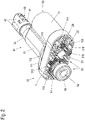
- FIG 1 shows the electromotive furniture drive initially in an overall view in an isometric representation.
- the furniture drive has a two-part housing 10 which includes an upper part 11 and a lower part 12 .
- Upper part 11 and lower part 12 are connected to one another with screws 13 .
- another type of connection can be provided between the two housing parts in addition or as an alternative, for example a latching, adhesive and/or welded connection.
- a fork head 121 is arranged on the lower part 12 and serves to couple the electromotive furniture drive to a fixed or movable furniture part or a fixed or movable part of a furniture fitting.
- a drive motor 20 On the opposite side of the housing 10 from the fork head 121 are located on the upper part 11 on the one hand a drive motor 20 and on the other hand a standpipe arrangement 30 with a standpipe 31.
- the drive motor 20 is shown in FIG 1 only a motor housing 21 can be seen.
- the drive motor 20 is preferably inserted with a motor flange (not visible here) into a recess in the upper part 11 and fastened there.
- the upper part 11 is higher than the area in which the flange of the drive motor 20 is positioned and has a dome 111 which ends in a collar 112 at its outer end.
- the standpipe 31 is inserted into this dome 111 and guided inside the dome 111 .
- a guide bushing 32 is fastened to the standpipe 31, in which a lifting tube 41 of a lifting tube arrangement 40 is displaceably guided.
- a clevis 42 is attached to the lifting tube 41, which lies in a line with the clevis 121 and is configured comparably.
- the fork head 42 serves to connect the electromotive furniture drive to a fixed or movable furniture part or a fixed or movable part of a furniture fitting.
- the upper part 11 and the lower part 12 of the housing 10 are preferably in each case plastic parts produced in one piece in an injection molding process.
- the fork head 42 and the guide bushing 32 are preferably plastic elements that are each produced in one piece in an injection molding process.
- the upright tube 31 and the lifting tube 41 are profile elements and are preferably made of a metal, in particular aluminum, in order to have the required stability despite the small wall thicknesses.
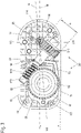
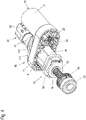
- FIG. 2 shows the electromotive furniture drive 1 in the same isometric view, but with the lower part 12 of the housing 10 removed in order to gain an insight into the internal structure of the furniture drive.
- the opened housing 10 is shown in a top view of the upper part 11 .
- a double worm gear 50 is accommodated in the housing 10 as a gear arrangement, through which a rotation of an output shaft 22 of the drive motor 20 is transmitted to a lifting spindle 52 . From the lifting spindle 52 is in the 2 and 3 only one free end is visible, which is mounted in a bearing 53, preferably a roller bearing. The bearing 53 is supported in the lower part 12 of the housing 10 and transmits forces from there directly to the fork head 121.
- the double worm gear 50 comprises an intermediate shaft 51 which runs perpendicularly to the output shaft 22 and the lifting spindle 52 .
- the intermediate shaft 51 is mounted in the housing 10 with bearing journals 511, 512, half-shell-shaped slide bearings being formed in both the upper part 11 and the lower part 12.
- the intermediate shaft 51 is inserted into the upper part 11, as shown in 2 and 3 is visible.
- the bearing shells in the upper part 11 and lower part 12 complement each other to form plain bearings for the intermediate shaft 51.
- a worm also called motor worm 23 in the following, is placed or formed on the output shaft 22 and engages in a worm wheel, also called the intermediate wheel 513 in the following, of the intermediate shaft 51 .
- a further worm 514 is also formed on the intermediate shaft 51 and engages in a further worm wheel which is mounted on the lifting spindle 52 in a rotationally fixed manner and is referred to below as the spindle wheel 54 .
- the footprint of the housing 10 is substantially that of a rectangle with rounded edges.
- the corners are rounded off to form a continuous semicircle, the diameter of which is only slightly larger than the diameter of the motor housing 21 .
- the upper part 11 of the housing 10 is delimited by parallel and straight longitudinal sides 115. Centrally between these longitudinal sides 115 runs a central plane M of the housing 10 in the 3 is drawn in dashed.
- Next is in the 3 drawn in the plane in which the output shaft 22 and the lifting spindle 52 lie. This level is referred to below as (axis) level A.
- the output shaft 22 is in the center plane M of the housing 10, but the lifting spindle 52 is arranged eccentrically.
- the axis plane A and the center plane M intersect in the output shaft 22.
- the intermediate shaft 51 not only crosses the axis plane A, but also the center plane M.
- the intermediate wheel 513 can have a diameter d (see 3 ) Have, which is at least as large as the distance between the longitudinal sides 115 to the center plane M. This distance is as b / 2 in the 3 drawn in, where b indicates the distance between the two longitudinal sides 115 of the housing and thus a width of the housing in the direction perpendicular to the center plane M. Due to the inclined position of the intermediate shaft 51 in the housing 10, a large transmission ratio can be achieved without the housing 10 having to be widened in an orientation perpendicular to the center plane M.
- a compact housing is achieved in that the lifting spindle 52 is arranged eccentrically in the housing 10 with respect to the center plane M. This is on the side on which the worm 514 of the intermediate shaft 51 enters the Spindle wheel 54 engages, more space to store the bearing pin 512 in the housing 10 can.
- Another measure to be able to store the intermediate shaft 51 in a housing 10 that is as compact as possible and in particular to be able to use the largest possible intermediate wheel 513 is to place the bearing shells for the bearing journals 511, 512 as close as possible to or, as shown, right into a wall of the housing 10 to extend.
- a recess is also provided in the wall of the housing 10 in the region of the circumference of the intermediate wheel 513, into which the intermediate wheel 513 protrudes in order to be able to use an intermediate wheel 513 which is as large as possible.
- the dome 111 with the collar 112 is formed on the upper part 11 of the housing 10, into which the standpipe 31 fits exactly.
- the standpipe 31 is subsequently in connection with figure 5 described in more detail.
- a clamping ring 33 is placed around the standpipe 31 in an end region of the standpipe 31 which faces the spindle wheel 54 . This clamping ring 33 engages in transverse grooves of the upright tube 31 and is therefore not displaceable in the longitudinal direction relative to the upright tube 31 .
- the clamping ring 33 When the standpipe 31 is inserted into the upper part 11, the clamping ring 33 rests in a recess in the upper part 11 that is adapted to its circumference. In this way, the clamping ring 33 is fixed in the direction of the dome 111 or collar 112 and with regard to its lateral position in the upper part 11 . If the housing 10 is closed by placing the lower part 12 on and connecting the lower part 12 to the upper part 11, correspondingly shaped projections of the lower part 12 press on the still accessible edge of the clamping ring 33, as a result of which this is also positively fixed in the housing 10 in the direction of the lower part 12 .
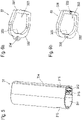
- FIG 5 shows the standpipe 31 separately in an isometric drawing.
- the standpipe 31 has an asymmetrical profile with a main shaft 311, in which the lifting spindle 52 and the lifting tube 41 are located.
- the main shaft 311 has an approximately round cross section.
- On a flattened side 314 of the standpipe 31 there is also a limit switch shaft 212 running in the longitudinal direction, in which microswitches, which act as limit switches for the electromotive furniture drive, are positioned.
- microswitches which act as limit switches for the electromotive furniture drive, are positioned.
- Between the two shafts there is at least one longitudinal web 313 which also runs over the entire length.
- a spindle nut engages in this at least one longitudinal web 313 so that it can move in the longitudinal direction in the standpipe 31 but is secured against twisting.
- transverse grooves 315 are made in the standpipe 31 from the outside, into which the clamping ring 33 is inserted and through which the standpipe 31 is fixed in the housing 10 in the longitudinal direction with the aid of the clamping ring 33 .
- FIG. 6a Two embodiments of suitable clamping rings 33 are in the Figures 6a and 6b each shown in an isometric representation.
- the clamping ring 33 shown is also in 4 visible. It is made of two interlocking sections 331 and 332 in order to be able to insert the standpipe 31 into the transverse grooves 315 embracing. Correspondingly, it has two straight webs 333 on the inside, which engage in the transverse grooves 315 .
- a mounting option 334 for a screw or a locking head is also provided in order to hold the clamping ring 33 in position before the housing 10 is closed.
- the alternatively usable clamping ring 33 according to Figure 6b has two mutually pivotable sections 331, 332, which on one side (in the Figure 6b on the right) are connected to each other via a hinge 335.
- a locking mechanism 336 is provided on the opposite side in order to be able to close the clamping ring 33 .
- the one-piece design of the clamping ring 33 achieved in this way simplifies the assembly process.
- FIG. 7 finally shows the overall structure of the electromotive furniture drive Figures 1 to 4 again in a sectional view.
- An offset section has been selected in this representation, in which the section in the center plane M (cf. 3 ) runs. In the area of the standpipe 31 or lifting tube 41, the section runs in a parallel plane centrally through the lifting spindle 52.
- Two limit switches 316 can also be seen in this illustration, which are actuated by an extension on the spindle nut 43 and switch off the drive motor 20 directly or via control electronics when one or the other end position is reached.
Landscapes
- Engineering & Computer Science (AREA)
- General Engineering & Computer Science (AREA)
- Mechanical Engineering (AREA)
- Health & Medical Sciences (AREA)
- General Health & Medical Sciences (AREA)
- Nursing (AREA)
- Gear Transmission (AREA)
- Transmission Devices (AREA)
- Connection Of Motors, Electrical Generators, Mechanical Devices, And The Like (AREA)
Description
- Die Erfindung betrifft einen elektromotorischen Möbelantrieb mit einer Hubspindel und einem Antriebsmotor, wobei die Hubspindel und eine Abtriebswelle des Antriebsmotors in einer gemeinsamen Ebene angeordnet sind, und wobei die Abtriebswelle über eine Getriebeanordnung mit einer Zwischenwelle mit der Hubspindel gekoppelt ist. Der elektromotorische Möbelantrieb weist ein Gehäuse auf, in dem die Getriebeanordnung aufgenommen ist und von dem an einer Seite ein Motorgehäuse des Antriebsmotors und ein Standrohr parallel zueinander abstehen, wobei in dem Standrohr ein Hubrohr linear verfahrbar gelagert ist, das mit einer Spindelmutter gekoppelt ist, die mit der Hubspindel zusammenwirkt, wobei die Zwischenwelle die Ebene, in der die Hubspindel und die Abtriebswelle liegen, zwischen der Hubspindel und der Abtriebswelle schneidet.
- Elektromotorische Möbelantriebe werden in Möbeln, beispielsweise Schlaf-oder Ruhemöbel wie Betten, Schlafsofas oder Sesseln eingesetzt, um wenigstens ein bewegbares Möbelteil relativ zu einem weiteren Möbelteil bequem verstellen, beispielsweise verschwenken zu können. Bei einem Bett kann beispielsweise ein Rücken- oder Beinteil gegenüber einem Mittelteil des Bettes angehoben oder abgesenkt werden.
- Möbelantriebe mit einer Hubspindel, häufig auch als Spindelantriebe bezeichnet, eignen sich insbesondere als Linearantriebe, deren Abtriebsglied linear gegenüber einem Grundkörper des Möbelantriebs verfahrbar ist. Häufig sind zwei ineinander einfahrbare Rohrprofile vorgesehen, ein Standrohr und ein Hubrohr, wobei die Hubspindel drehbar aber ortsfest zum Standrohr angeordnet ist und eine Spindelmutter mit dem Hubrohr gekoppelt ist, um das Hubrohr beim Drehen der Hubspindel aus dem Standrohr heraus- bzw. in das Standrohr hinein zu verfahren. In alternativen Ausgestaltungen kann vorgesehen sein, die Hubspindel verschiebbar aber drehfest auszubilden und die Spindelmutter über den Antriebsmotor anzutreiben und drehbar aber ortsfest zu lagern. Eine Ausgestaltung mit ortsfester Spindel und ineinander fahrbarem Stand- bzw. Hubrohr stellt jedoch in der Regel die kompaktere Anordnung dar.
- Aus der Druckschrift
DE 102 54 127 A1 ist ein Möbelantrieb mit einer Hubspindel und einem Antriebsmotor mit Abtriebswelle bekannt, bei dem die Abtriebswelle und die Hubspindel parallel zueinander in einer gemeinsamen Ebene angeordnet sind. Die Abtriebswelle des Antriebsmotors ist dabei über ein Doppelschneckengetriebe mit der Hubspindel gekoppelt. Zu diesem Zweck ist auf der Abtriebswelle des Antriebsmotors eine erste Schnecke angeordnet, die mit einem Schneckenrad einer Zwischenwelle im Eingriff ist. Die Zwischenwelle weist eine zweite Schnecke auf, die mit einem Schneckenrad kämmt, das auf der Hubspindel montiert ist. Die Zwischenwelle ist dabei senkrecht zur Richtung der Abtriebswelle und der Hubspindel ausgerichtet. Als Besonderheit weist das Getriebe dabei zwei Übertragungsstränge auf, indem zwei identisch ausgebildete Zwischenwellen die Drehbewegung der ersten Schnecke auf das Schneckenrad der Hubspindel übertragen. Jeweils eine der Zwischenwellen ist auf einer Seite der Ebene angeordnet, in der die Abtriebswelle des Antriebsmotors und die Hubspindel liegen. Die beiden Zwischenwellen selbst sind dabei entweder parallel zueinander angeordnet oder verlaufen vom Antriebsmotor aus gesehen v-förmig nach außen. Grundsätzlich stellt der Durchmesser des Motors eine untere Grenze für die Ausdehnung des Möbelantriebs in einer Richtung senkrecht zu der genannten Ebene, in der die Abtriebswelle des Antriebsmotors und die Hubspindel liegen, dar. - Wenn bei der Anordnung der Zwischenwellen gemäß der Druckschrift
DE 102 54 127 A1 der Durchmesser der Schneckenräder der Zwischenwellen größer als der halbe Durchmesser des Motorgehäuses ist, ragen die Ränder der Schneckenräder der Zwischenwellen in einer Richtung senkrecht zur genannten Ebene über das Motorgehäuse hinaus und bestimmen die minimale Ausdehnung des Gehäuses des Möbelantriebs in dieser Richtung. Aufgrund des gewünschten Übersetzungsverhältnisses zwischen Antriebsmotor und Hubspindel und um einen guten Eingriff zwischen Schnecke und Schneckenrad zu erzielen, kann ein Durchmesser der Schneckenräder jedoch nicht beliebig klein gewählt werden. - Gemäß der Druckschrift
DE 20 2016 106 011 U1 ist bei einem elektromotorischen Möbelantrieb der oben genannten Art ein zweistufiges Schneckengetriebe vorgesehen, über das ein Antriebsmotor mit einer Hubspindel gekoppelt ist, die in einem Standrohr angeordnet ist. Die Zwischenwelle schneidet dabei die Ebene, in der die Hubspindel und die Abtriebswelle liegen, zwischen der Hubspindel und der Abtriebswelle. Die Zwischenwelle liegt somit quer zu der Hubspindel, wodurch ein kompakter Aufbau möglich wird. Es ist ein inneres Getriebegehäuse vorhanden, um die Zwischenwelle zu lagern und ein längsgeteiltes äußeres Getriebegehäuse, das das innere Gehäuse umgibt und an dem der Antriebsmotor und das Standrohr montiert sind. Die ineinander verschachtelten Gehäuse verkomplizieren jedoch die Montage des Möbelantriebs. - Es ist eine Aufgabe der vorliegenden Erfindung, einen elektromotorischen Möbelantrieb der eingangs genannten Art zu schaffen, bei dem möglichst große Schneckenräder bei der Getriebeanordnung eingesetzt werden können, ohne dass diese einer kompakten Ausgestaltung des elektromotorischen Möbelantriebs entgegenstehen und das einfach montiert werden kann.
- Diese Aufgabe wird gelöst durch einen elektromotorischen Möbelantrieb mit den Merkmalen des unabhängigen Anspruchs. Vorteilhafte Ausgestaltungen und Weiterbildungen sind Gegenstand der abhängigen Ansprüche.
- Bei einem elektromotorischen Möbelantrieb der eingangs genannten Art schneidet die Zwischenwelle der Getriebeanordnung die Ebene, in der die Hubspindel und die Abtriebswelle liegen, zwischen der Hubspindel und der Abtriebswelle. Die Zwischenwelle liegt entsprechend quer zwischen der Hubspindel und der Abtriebswelle und damit auch quer im (Getriebe-) Gehäuse und greift an jeweils unterschiedlichen Seiten der Hubspindel und Abtriebswelle in diese ein. Der zur Verfügung stehende Platz kann so gut ausgenutzt werden, wodurch das Gehäuse und damit auch der Möbelantrieb besonders kompakt aufgebaut werden kann.
- Erfindungsgemäß weist das Gehäuse ein Oberteil auf, von dem das Motorengehäuse, der Antriebsmotor und das Standrohr abstehen, und ein an einer gegenüberliegenden Seite angeordnetes Unterteil. So können alle Komponenten in oder an dem nur einen Gehäuse gut zugänglich montiert werden.
- In einer vorteilhaften Ausgestaltung des elektromotorischen Möbelantriebs ist die Getriebeanordnung als Doppelschneckengetriebe ausgebildet, wobei die Zwischenwelle ein Zwischenrad aufweist, in das eine Schnecke der Abtriebswelle des Antriebsmotors eingreift, und eine weitere Schnecke, die in ein Spindelrad der Hubspindel eingreift.
- Alternativ kann die Getriebeanordnung eine Kombination aus einem Schneckengetriebe und einem Schraubengetriebe sein, wobei die Zwischenwelle ein Zwischenrad aufweist, in das eine Schnecke der Abtriebswelle des Antriebsmotors eingreift, und ein Schraubenrad, das in ein Schraubenrad der Hubspindel eingreift.
- Bevorzugt schneidet die Zwischenwelle die Ebene in einem Winkel von 30° bis 75° und besonders bevorzugt von 35° bis 45°. Durch die Schrägstellung der Zwischenwelle im Gehäuse ist das Zwischenrad ebenfalls schräg gegenüber Gehäuseseiten angeordnet, wodurch das Zwischenrad größer ausgelegt werden kann, als wenn es in einer Ebene liegt, die parallel oder senkrecht zu einer Gehäuseseite verläuft.
- Bevorzugt weist das Gehäuse zwei parallele Längsseiten auf, die einen Abstand zueinander haben, wobei ein Durchmesser des Zwischenrad größer oder gleich dem halben Abstand der Längsseiten ist. Der Abstand der Längsseiten, d.h. die Ausdehnung des Gehäuses in der Richtung senkrecht zu den Längsseiten kann dadurch in einer Ausgestaltung im Wesentlichen einer Abmessung des Motorgehäuses in dieser Richtung entsprechen. Mit anderen Worten kann das Gehäuse in dieser Richtung so schmal ausgestaltet werden, dass es nicht oder nur unwesentlich breiter ist als das Motorgehäuse.
- In einer weiteren vorteilhaften Ausgestaltung liegt dabei die Abtriebswelle mittig zwischen den parallelen Längsseiten, wohingegen die Hubspindel außermittig zwischen den parallelen Längsseiten angeordnet ist. Dieses gibt auf der Seite, auf der die Zwischenwelle mit der Hubspindel zusammenwirkt, mehr Platz, um beispielsweise die Zwischenwelle im Gehäuse lagern zu können.
- In einer weiteren vorteilhaften Ausgestaltung des elektromotorischen Möbelantriebs umfasst das Unterteil einen Gabelkopf oder eine vergleichbare Anbindungsmöglichkeit des elektromotorischen Möbelantriebs. Der Gabelkopf bzw. die Anbindungsmöglichkeit ist bevorzugt mit dem Unterteil ausgebildet und liegt in einer Flucht mit dem Hubrohr.
- In einer weiteren vorteilhaften Ausgestaltung des elektromotorischen Möbelantriebs ist die Zwischenwelle mit Lagerzapfen in Gleitlagern gelagert, wobei Lagerschalen in Ober- und Unterteil ausgebildet sind. Bevorzugt ergänzen sich jeweils eine halbschalenförmige Lagerschale im Oberteil und eine halbschalenförmige Lagerschale im Unterteil zu einem Gleitlager für einen der Lagerzapfen. Eine derartige Lagerung der Zwischenwelle ist platzsparend und wirkt sich entsprechend nicht oder nur unwesentlich auf die Größe des Gehäuses aus. Sie ist zudem kostengünstig und die Zwischenwelle ist einfach zu montieren.
- In einer weiteren vorteilhaften Ausgestaltung des elektromotorischen Möbelantriebs weist das Oberteil des Gehäuses im Bereich des Standrohrs einen erhöhten Dom auf, in den das Standrohrs seitlich formschlüssig eingesetzt ist. Ggf. auf das Standrohr wirkende Querkräfte (d.h. Kräfte, die quer zur Hubrichtung des Hubrohrs wirken) können so gut auf das Gehäuse übertragen werden. Durch einen möglichst passgenauen Formschluss braucht das Standrohr zusätzlich nur noch im Hinblick auf seine Längsrichtung mit dem Gehäuse verbunden werden. Dieses erfolgt bevorzugt, indem das Standrohr mindestens eine in eine Außenwandung eingebrachte Quernut aufweist, wobei um das Standrohr ein Klemmring gelegt ist, der in die mindestens eine Quernut eingreift. Der Klemmring wird um das Standrohr gelegt und dieses mit dem Klemmring in das Oberteil des (noch geöffneten) Gehäuses eingeschoben. Im Oberteil ist dann eine Aussparung vorhanden, die den Klemmring aufnimmt, und zwar zu bevorzugt allen Seiten entlang seines Umfangs formschlüssig. Das dann aufgesetzt Unterteil des Gehäuses ist so gestaltet, dass es in der Hubrichtung an
mindestens einer, bevorzugt mehreren Stellen bis auf den Klemmring reicht und ihn dadurch auch in der Hubrichtung durch Formschluss hält. - In einer Ausgestaltung kann der Klemmring aus zwei Abschnitten gebildet sein, die ineinander steckbar sind, um den Klemmring um das Standrohr und in dessen mindestens eine Quernut einzulegen. In einer dazu alternativen Ausgestaltung ist der Klemmring aus zwei Abschnitten gebildet, die über ein Scharnier klappbar miteinander verbunden sind.
- Die Erfindung wird nachfolgend anhand eines Ausführungsbeispiels mit Hilfe von Figuren näher erläutert. Die Figuren zeigen:
- Fig. 1
- eine isometrische Darstellung eines elektromotorischen Möbelantriebs;
- Fig. 2
- der elektromotorische Möbelantrieb aus
Fig. 1 mit geöffnetem Gehäuse; - Fig. 3
- eine Draufsicht auf das geöffnete Gehäuse der
Fig. 2 ; - Fig. 4
- der elektromotorische Möbelantrieb der
Fig. 1 bis 3 in einem teilmontierten Zustand in einer isometrischen Darstellung; - Fig. 5
- eine isometrische Darstellung eines Standrohrs eines elektromotorischen Möbelantriebs;
- Fig. 6a, b
- zwei Ausführungsbeispiele von Klemmringen zur Befestigung des Standrohrs der
Fig. 5 ; und - Fig. 7
- eine Schnittdarstellung des Möbelantriebs der
Fig. 1 bis 4 . - In den Figuren ist ein Ausführungsbeispiel eines elektromotorischen Möbelantriebs in verschiedenen Darstellungen gezeigt. In allen Figuren kennzeichnen gleiche Bezugszeichen gleiche Elemente.
-
Fig. 1 zeigt den elektromotorischen Möbelantrieb zunächst in einer Gesamtansicht in einer isometrischen Darstellung. - Der Möbelantrieb weist ein zweiteiliges Gehäuse 10 auf, das ein Oberteil 11 und ein Unterteil 12 umfasst. Oberteil 11 und Unterteil 12 sind mit Schrauben 13 miteinander verbunden. In Weiterbildungen des gezeigten Möbelantriebs kann zusätzlich oder alternativ eine andere Verbindungsart zwischen den beiden Gehäuseteilen vorgesehen sein, beispielsweise eine Rast-, Klebe-und/oder eine Schweißverbindung. Am Unterteil 12 ist ein Gabelkopf 121 angeordnet, der der Kopplung des elektromotorischen Möbelantriebs mit einem festen oder beweglichen Möbelteil dient oder einem festen oder beweglichen Teil eines Möbelbeschlags.
- Auf der dem Gabelkopf 121 gegenüberliegenden Seite des Gehäuses 10 befinden sich am Oberteil 11 zum einen ein Antriebsmotor 20 und zum anderen eine Standrohranordnung 30 mit einem Standrohr 31. Vom Antriebsmotor 20 ist in der Darstellung der
Fig. 1 nur ein Motorgehäuse 21 zu sehen. Der Antriebsmotor 20 ist mit einem hier nicht sichtbaren Motorflansch bevorzugt in eine Vertiefung des Oberteils 11 eingesetzt und dort befestigt. - Im Bereich des Standrohrs 31 ist das Oberteil 11 gegenüber dem Bereich, in dem der Flansch des Antriebsmotors 20 positioniert ist, erhöht und weist einen Dom 111 auf, der an seinem äußeren Ende in einem Kragen 112 mündet. Das Standrohr 31 ist in diesen Dom 111 eingesteckt und innerhalb des Doms 111 geführt. An dem dem Gehäuse 10 gegenüberliegenden freien Ende des Standrohrs 31 ist eine Führungsbuchse 32 an dem Standrohr 31 befestigt, in der ein Hubrohr 41 einer Hubrohranordnung 40 verschiebbar geführt ist.
- Am äußeren Ende ist an dem Hubrohr 41 ein Gabelkopf 42 befestigt, der in einer Linie mit dem Gabelkopf 121 liegt und vergleichbar ausgestaltet ist. Der Gabelkopf 42 dient ebenso wie der Gabelkopf 121 der Anbindung des elektromotorischen Möbelantriebs an ein festes oder bewegbares Möbelteil bzw. ein festes oder bewegbares Teil eines Möbelbeschlags.
- Das Oberteil 11 und das Unterteil 12 des Gehäuses 10 sind bevorzugt jeweils einteilig in einem Spritzgussverfahren hergestellte Kunststoffteile. Ebenso sind der Gabelkopf 42 und die Führungsbuchse 32 bevorzugt Kunststoffelemente, die in einem Spritzgussverfahren jeweils einteilig hergestellt sind. Das Standrohr 31 und das Hubrohr 41 sind dagegen Profilelemente und bevorzugt aus einem Metall, insbesondere Aluminium gefertigt, um trotz geringer Wandstärken eine benötigte Stabilität aufzuweisen.
-
Fig. 2 zeigt den elektromotorischen Möbelantrieb ausFig. 1 in gleicher isometrischer Ansicht, wobei jedoch das Unterteil 12 des Gehäuses 10 abgenommen ist, um Einblick in den inneren Aufbau des Möbelantriebs zu erhalten. InFig. 3 ist das geöffnete Gehäuse 10 in einer Draufsicht auf das Oberteil 11 wiedergegeben. - In den
Fig. 2 und3 sind im Oberteil 11 Schraubdome 113 zu erkennen, in die die Schrauben 13 eingeschraubt sind. Im Unterteil 11 sind entsprechend Schraubendurchführungen vorhanden. Um ein geringes Gewicht bei gleichzeitig hoher Stabilität zu erzielen sind im Ober- und Unterteil 11, 12 Verstärkungsstege 114 ausgebildet, z.B. wie dargestellt in einem Gittermuster. - Im Gehäuse 10 ist ein Doppelschneckengetriebe 50 als Getriebeanordnung aufgenommen, durch die eine Drehung einer Abtriebswelle 22 des Antriebsmotors 20 auf eine Hubspindel 52 übertragen wird. Von der Hubspindel 52 ist in den
Fig. 2 und3 nur ein freies Ende sichtbar, das in einem Lager 53, bevorzugt einem Wälzkörperlager, gelagert ist. Das Lager 53 stützt sich im Unterteil 12 des Gehäuses 10 ab und überträgt Kräfte von dort unmittelbar auf den Gabelkopf 121. - Das Doppelschneckengetriebe 50 umfasst eine Zwischenwelle 51, die senkrecht zu der Abtriebswelle 22 und der Hubspindel 52 verläuft. Die Zwischenwelle 51 ist mit Lagerzapfen 511, 512 im Gehäuse 10 gelagert, wobei sowohl im Oberteil 11 als auch im Unterteil 12 halbschalenförmige Gleitlager ausgebildet sind. Zur Montage wird die Zwischenwelle 51 in das Oberteil 11 eingelegt, wie in
Fig. 2 und3 sichtbar ist. Beim Verschließen des Gehäuses 10 ergänzen sich die Lagerschalen im Oberteil 11 und Unterteil 12 zu Gleitlagern für die Zwischenwelle 51. - Auf die Abtriebswelle 22 aufgesetzt oder angeformt ist eine Schnecke, nachfolgend auch Motorschnecke 23 genannt, die in ein Schneckenrad, nachfolgend auch Zwischenrad 513 genannt, der Zwischenwelle 51 eingreift. Weiter ist an der Zwischenwelle 51 eine weitere Schnecke 514 ausgebildet, die in ein weiteres Schneckenrad eingreift, das drehfest an der Hubspindel 52 montiert ist und nachfolgend als Spindelrad 54 bezeichnet wird.
- Durch die Ausgestaltung der Getriebeanordnung als Doppelschneckenantrieb 50 wird ein großes Übersetzungsverhältnis zwischen der Abtriebswelle 22 und der Hubspindel 52 erzielt. Entsprechend kann ein hochtourig drehender Antriebsmotor 20 verwendet werden, der bei gleicher Leistung wie ein niedertouriger Motor in der Regel eine kleinere Bauweise aufweist. Somit trägt bereits der Einsatz eines Doppelschneckengetriebes zu einer kompakten Bauweise bei.
- Weiterhin wird eine kompakte Bauweise dadurch erreicht, dass die Zwischenwelle 51 eine gemeinsame Ebene, in der die Abtriebswelle 22 und die Hubspindel 52 liegen, kreuzt.
- Wie insbesondere gut in der
Fig. 3 zu sehen ist, ist die Grundfläche des Gehäuses 10 im Wesentlichen die eines Rechtecks mit abgerundeten Kanten. Auf Seiten des Antriebsmotors 20 sind die Ecken bis zu einem durchgehenden Halbkreis abgerundet, dessen Durchmesser nur geringfügig über dem Durchmesser des Motorgehäuses 21 liegt. Nach oben und unten in derFig. 3 ist das Oberteil 11 des Gehäuses 10 durch parallele und gerade Längsseiten 115 begrenzt. Mittig zwischen diesen Längsseiten 115 verläuft eine Mittelebene M des Gehäuses 10, die in derFig. 3 gestrichelt eingezeichnet ist. Weiter ist in derFig. 3 die Ebene eingezeichnet, in der die Abtriebswelle 22 und die Hubspindel 52 liegen. Diese Ebene wird nachfolgend als (Achs-) Ebene A bezeichnet. -
Fig. 3 zeigt, dass die Abtriebswelle 22 in der Mittelebene M des Gehäuses 10 liegt, die Hubspindel 52 jedoch außermittig angeordnet ist. Entsprechend schneiden sich die Achsebene A und die Mittelebene M in der Abtriebswelle 22. Die Zwischenwelle 51 kreuzt im dargestellten Beispiel nicht nur die Achsebene A, sondern auch die Mittelebene M. - Durch die erreichte Schrägstellung der Zwischenwelle 51 im Gehäuse 10 (im gezeigten Beispiel kreuzt die Zwischenwelle 51 beispielsweise die Mittelebene M in einem Winkel von etwa 40°) kann das Zwischenrad 513 einen Durchmesser d (siehe
Fig. 3 ) aufweisen, der mindestens so groß ist wie der Abstand der Längsseiten 115 zur Mittelebene M. Dieser Abstand ist als b/2 in derFig. 3 eingezeichnet, wobei b den Abstand der beiden Längsseiten 115 des Gehäuses und damit eine Breite des Gehäuses in der Richtung senkrecht zur Mittelebene M angibt. Durch die Schrägstellung der Zwischenwelle 51 im Gehäuse 10 kann ein großes Übersetzungsverhältnis erzielt werden, ohne dass das Gehäuse 10 in einer Ausrichtung senkrecht zur Mittelebene M verbreitert werden müsste. - Weiter wird ein kompaktes Gehäuse dadurch erzielt, dass die Hubspindel 52 im Hinblick auf die Mittelebene M außermittig im Gehäuse 10 angeordnet ist. Dieses gibt auf der Seite, auf der die Schnecke 514 der Zwischenwelle 51 in das Spindelrad 54 eingreift, mehr Platz, um den Lagerzapfen 512 im Gehäuse 10 lagern zu können.
- Eine weitere Maßnahme, um die Zwischenwelle 51 in einem möglichst kompakten Gehäuse 10 lagern zu können und insbesondere ein möglichst großes Zwischenrad 513 einsetzen zu können, besteht darin, die Lagerschalen für die Lagerzapfen 511, 512 möglichst nah an bzw. wie gezeigt bis in eine Wandung des Gehäuses 10 zu erstrecken. Im Bereich des Umfangs des Zwischenrads 513 ist im gezeigten Beispiel darüber hinaus eine Aussparung in der Wandung des Gehäuses 10 vorgesehen, in die das Zwischenrad 513 ragt, um ein möglichst großes Zwischenrad 513 einsetzen zu können.
-
Fig. 4 zeigt wiederum in einer isometrischen Darstellung den elektromotorischen Möbelantrieb vergleichbar mit derFig. 2 , wobei jedoch das Standrohr 31 nur teilweise eingesetzt ist, um die Befestigung des Standrohrs 31 im Gehäuse 10 zu verdeutlichen. In dieserFig. 4 ist auch ein Gewindebereich der Spindel 52 zu erkennen. - Wie bereits im Zusammenhang mit
Fig. 1 erwähnt ist, ist am Oberteil 11 des Gehäuses 10 der Dom 111 mit dem Kragen 112 ausgebildet, in den passgenau das Standrohr 31 eingesetzt wird. Das Standrohr 31 wird nachfolgend im Zusammenhang mitFig. 5 noch näher beschrieben. In einem Endbereich des Standrohrs 31, der dem Spindelrad 54 zugewandt ist, ist um das Standrohr 31 ein Klemmring 33 gelegt. Dieser Klemmring 33 greift in Quernuten des Standrohrs 31 ein und ist damit in Längsrichtung gegenüber dem Standrohr 31 nicht verschiebbar. - Beim Einsetzen des Standrohrs 31 in das Oberteil 11 liegt der Klemmring 33 in einer an seinem Umfang angepassten Vertiefung im Oberteil 11 an. Auf diese Weise ist der Klemmring 33 in Richtung des Doms 111 bzw. des Kragens 112 sowie im Hinblick auf seine seitliche Position im Oberteil 11 festgelegt. Wird das Gehäuse 10 durch Aufsetzen des Unterteils 12 und Verbinden des Unterteils 12 mit dem Oberteil 11 geschlossen, drücken entsprechend ausgeformte Vorsprünge des Unterteils 12 auf den noch zugänglichen Rand des Klemmrings 33, wodurch dieser auch in Richtung des Unterteils 12 formschlüssig im Gehäuse 10 festgelegt ist.
-
Fig. 5 zeigt das Standrohr 31 in einer isometrischen Zeichnung separat. Das Standrohr 31 hat ein asymmetrisches Profil mit einem Hauptschacht 311, in dem sich die Hubspindel 52 und das Hubrohr 41 befinden. Der Hauptschacht 311 hat einen annähernd runden Querschnitt. An einer abgeflachten Seite 314 des Standrohrs 31 ist ein ebenfalls in Längsrichtung verlaufender Endschalterschacht 212 ausgebildet, in dem Mikroschalter, die als Endschalter für den elektromotorischen Möbelantrieb fungieren, positioniert sind. Zwischen dem Hauptschacht 311 und dem Endschalterschacht 312 besteht eine über die gesamte Länge offene Verbindung. Zwischen den beiden Schächten ist mindestens ein ebenfalls über die gesamte Länge verlaufender Längssteg 313 vorhanden. Eine hier nicht dargestellte Spindelmutter greift in diesen mindestens einen Längssteg 313 ein, sodass sie sich in Längsrichtung im Standrohr 31 bewegen kann, aber gegen Verdrehung gesichert ist. - An der abgeflachten Seite 314 und auch an der gegenüberliegenden Rundung sind Quernuten 315 von außen in das Standrohr 31 eingebracht, in die der Klemmring 33 eingelegt wird und durch die das Standrohr 31 in Längsrichtung mithilfe des Klemmrings 33 im Gehäuse 10 fixiert wird.
- Zwei Ausführungsbeispiele von geeigneten Klemmringen 33 sind in den
Fig. 6a und 6b in jeweils einer isometrischen Darstellung gezeigt. Der inFig. 6a gezeigte Klemmring 33 ist der auch inFig. 4 sichtbare. Er ist aus zwei ineinandergreifenden Abschnitten 331 und 332 gefertigt, um das Standrohr 31 umgreifend in die Quernuten 315 eingelegt werden zu können. Er weist entsprechend innenseitig zwei gerade Stege 333 auf, die in die Quernuten 315 eingreifen. Bei dem Beispiel derFig. 6a ist noch eine Befestigungsmöglichkeit 334 für eine Schraube oder einen Rastkopf vorgesehen, um den Klemmring 33 vor dem Schließen des Gehäuses 10 in Position zu halten. - Der alternativ verwendbare Klemmring 33 gemäß
Fig. 6b weist zwei gegeneinander verschwenkbare Abschnitte 331, 332 auf, die auf einer Seite (in derFig. 6b auf der rechten Seite) über einen Scharnier 335 miteinander verbunden sind. Auf der gegenüberliegenden Seite ist ein Rastmechanismus 336 vorgesehen, um den Klemmring 33 schließen zu können. Die so erzielte einstückige Ausbildung des Klemmrings 33 vereinfacht den Montageprozess. -
Fig. 7 zeigt schließlich den Gesamtaufbau des elektromotorischen Möbelantriebs derFig. 1 bis 4 nochmals in einer Schnittdarstellung. Es ist ein versetzter Schnitt in dieser Darstellung gewählt, bei dem im Bereich des Antriebsmotors 20 der Schnitt in der Mittelebene M (vgl.Fig. 3 ) verläuft. Im Bereich des Standrohrs 31 bzw. Hubrohrs 41 verläuft der Schnitt in einer dazu parallelen Ebene zentral durch die Hubspindel 52. - In dieser Schnittdarstellung ist die bereits erwähnte Spindelmutter 43 und ihr Eingriff in die Längsstege 313, die den Endschalterschacht 312 vom Hauptschacht 311 des Standrohrs 31 trennen, sichtbar. Die Spindelmutter 43 ist fest mit dem Hubrohr 41 verbunden. Bei Rotation der Hubspindel 52 verfährt die Spindelmutter 43 und damit das Hubrohr 41 und der Gabelkopf 42 linear aus dem Standrohr 31 heraus bzw. in dieses hinein.
- Weiter sind in dieser Darstellung zwei Endschalter 316 zu erkennen, die von einem Fortsatz an der Spindelmutter 43 betätigt werden und unmittelbar oder über eine Steuerelektronik den Antriebsmotor 20 abschalten, wenn die eine oder andere Endstellung erreicht ist.
-
- 10
- Gehäuse
- 11
- Oberteil
- 111
- Dom
- 112
- Kragen
- 113
- Schraubdom
- 114
- Verstärkungssteg
- 115
- Längsseite
- 12
- Unterteil
- 121
- Gabelkopf
- 13
- Schraube
- 20
- Antriebsmotor
- 21
- Motorgehäuse
- 22
- Abtriebswelle
- 23
- erste Schnecke (Motorschnecke)
- 30
- Standrohranordnung
- 31
- Standrohr
- 311
- Hauptschacht
- 312
- Endschalterschacht
- 313
- Längssteg
- 314
- abgeflachte Seite
- 315
- Quernut
- 316
- Endschalter
- 32
- Führungsbuchse
- 33
- Klemmring
- 331,332
- Abschnitt
- 333
- Steg
- 334
- Befestigungsmöglichkeit
- 335
- Scharnier
- 336
- Rastmechanismus
- 34
- Spindelführung
- 40
- Hubrohranordnung
- 41
- Hubrohr
- 42
- Gabelkopf
- 43
- Spindelmutter
- 50
- Doppelschneckengetriebe
- 51
- Zwischenwelle
- 511,512
- Lagerzapfen
- 513
- Schneckenrad (Zwischenrad)
- 514
- weitere Schnecke
- 52
- Hubspindel
- 53
- Spindellager
- 54
- weiteres Schneckenrad (Spindelrad)
- A
- (Achs-) Ebene
- M
- Mittelebene
- d
- Durchmesser (des Zwischenrads)
- b
- Abstand (der Längsseiten)
Claims (15)
- Elektromotorischer Möbelantrieb mit einem Antriebsmotor (20) und einer Hubspindel (52), wobei die Hubspindel (52) und eine Abtriebswelle (22) des Antriebsmotors (20) in einer gemeinsamen Ebene (A) angeordnet sind, und wobei die Abtriebswelle (22) über eine Getriebeanordnung mit einer Zwischenwelle (51) mit der Hubspindel (52) gekoppelt ist, aufweisend ein Gehäuse (10), in dem die Getriebeanordnung aufgenommen ist und von dem an einer Seite ein Motorgehäuse (21) des Antriebsmotors (20) und ein Standrohr (31) parallel zueinander abstehen, wobei in dem Standrohr (31) ein Hubrohr (41) linear verfahrbar gelagert ist, das mit einer Spindelmutter (43) gekoppelt ist, die mit der Hubspindel (52) zusammenwirkt, wobei die Zwischenwelle (51) die Ebene (A), in der die Hubspindel (52) und die Abtriebswelle (22) liegen, zwischen der Hubspindel (52) und der Abtriebswelle (22) schneidet, dadurch gekennzeichnet, dass das Gehäuse (10) ein Oberteil (11) aufweist, von dem das Motorengehäuse (21), der Antriebsmotor (20) und das Standrohr (31) abstehen, und ein an einer gegenüberliegenden Seite angeordnetes Unterteil (12).
- Elektromotorischer Möbelantrieb nach Anspruch 1, bei dem die Getriebeanordnung ein Doppelschneckengetriebe (50) ist, wobei die Zwischenwelle (51) ein Zwischenrad (513) aufweist, in das eine Schnecke (23) der Abtriebswelle (22) des Antriebsmotors (20) eingreift, und eine weitere Schnecke (514), die in ein Spindelrad (54) der Hubspindel (52) eingreift.
- Elektromotorischer Möbelantrieb nach Anspruch 1, bei dem die Getriebeanordnung eine Kombination aus einem Schneckengetriebe und einem Schraubengetriebe ist, wobei die Zwischenwelle (51) ein Zwischenrad (513) aufweist, in das eine Schnecke (23) der Abtriebswelle (22) des Antriebsmotors (20) eingreift, und ein Schraubenrad, das in ein Schraubenrad der Hubspindel (52) eingreift.
- Elektromotorischer Möbelantrieb nach einem der Ansprüche 1 bis 3, bei dem die Zwischenwelle (51) die Ebene (A) in einem Winkel von 30° bis 75° und bevorzugt von 35° bis 45° schneidet.
- Elektromotorischer Möbelantrieb nach einem der Ansprüche 1 bis 4, bei dem die der Hubspindel (52) und der Abtriebswelle (22) parallel zueinander stehen und jeweils senkrecht zu der Zwischenwelle (51).
- Elektromotorischer Möbelantrieb nach den Ansprüchen 2 bis 5, bei dem das Gehäuse (10) zwei parallele Längsseiten (115) aufweist, die einen Abstand (b) zueinander haben, wobei ein Durchmesser (d) des Zwischenrad (513) größer oder gleich dem halben Abstand (b) ist.
- Elektromotorischer Möbelantrieb nach Anspruch 6, bei dem die Abtriebswelle (22) mittig zwischen den parallelen Längsseiten (115) liegt und die Hubspindel (52) außermittig zwischen den parallelen Längsseiten (115).
- Elektromotorischer Möbelantrieb nach Anspruch 6 oder 7, bei dem der Abstand (b) im Wesentlichen einer Abmessung des Motorgehäuses (22) in der Richtung des Abstands (b) entspricht.
- Elektromotorischer Möbelantrieb nach einem der Ansprüche 1 bis 8, bei dem die Zwischenwelle (51) mit Lagerzapfen (511, 512) in Gleitlagern gelagert ist, wobei Lagerschalen in Ober- und Unterteil (11, 12) ausgebildet sind.
- Elektromotorischer Möbelantrieb nach Anspruch 9, bei dem sich jeweils eine halbschalenförmige Lagerschale im Oberteil (11) und eine halbschalenförmige Lagerschale im Unterteil (12) zu einem Gleitlager für einen der Lagerzapfen (511, 512) ergänzen.
- Elektromotorischer Möbelantrieb nach einem der Ansprüche 1 bis 10, bei dem das Oberteil (11) im Bereich des Standrohrs (31) einen erhöhten Dom (111) aufweist, in den das Standrohrs (31) seitlich formschlüssig eingesetzt ist.
- Elektromotorischer Möbelantrieb nach Anspruch 11, bei dem das Standrohr (31) mindestens eine in eine Außenwandung eingebrachte Quernut (315) aufweist, wobei um das Standrohr (31) ein Klemmring (33) gelegt ist, der in die mindestens eine Quernut (315) eingreift.
- Elektromotorischer Möbelantrieb nach Anspruch 12, bei dem der Klemmring (33) formschlüssig in einer Aussparung zwischen dem Ober- und dem Unterteil (11, 12) gehalten ist.
- Elektromotorischer Möbelantrieb nach Anspruch 13, bei dem der Klemmring (33) aus zwei Abschnitten (331, 332) gebildet ist, die ineinander steckbar sind.
- Elektromotorischer Möbelantrieb nach Anspruch 14, bei dem der Klemmring (33) aus zwei Abschnitten (331, 332) gebildet ist, die über ein Scharnier (335) klappbar miteinander verbunden sind.
Applications Claiming Priority (2)
| Application Number | Priority Date | Filing Date | Title |
|---|---|---|---|
| DE102018106788.7A DE102018106788A1 (de) | 2018-03-22 | 2018-03-22 | Elektromotorischer Möbelantrieb mit einer Getriebeanordnung mit Zwischenwelle |
| PCT/EP2019/057270 WO2019180219A1 (de) | 2018-03-22 | 2019-03-22 | Elektromotorischer möbelantrieb mit einer getriebeanordnung mit zwischenwelle |
Publications (2)
| Publication Number | Publication Date |
|---|---|
| EP3768993A1 EP3768993A1 (de) | 2021-01-27 |
| EP3768993B1 true EP3768993B1 (de) | 2022-12-28 |
Family
ID=65904447
Family Applications (1)
| Application Number | Title | Priority Date | Filing Date |
|---|---|---|---|
| EP19713015.6A Active EP3768993B1 (de) | 2018-03-22 | 2019-03-22 | Elektromotorischer möbelantrieb mit einer getriebeanordnung mit zwischenwelle |
Country Status (7)
| Country | Link |
|---|---|
| US (1) | US11261948B2 (de) |
| EP (1) | EP3768993B1 (de) |
| CN (1) | CN111886425B (de) |
| DE (1) | DE102018106788A1 (de) |
| DK (1) | DK3768993T3 (de) |
| ES (1) | ES2941481T3 (de) |
| WO (1) | WO2019180219A1 (de) |
Families Citing this family (6)
| Publication number | Priority date | Publication date | Assignee | Title |
|---|---|---|---|---|
| DE102018106788A1 (de) * | 2018-03-22 | 2019-09-26 | Dewertokin Gmbh | Elektromotorischer Möbelantrieb mit einer Getriebeanordnung mit Zwischenwelle |
| DE202019103356U1 (de) * | 2019-06-14 | 2020-09-15 | Dewertokin Gmbh | Entstörter Linearantrieb |
| DE102021122792A1 (de) | 2021-09-02 | 2023-03-02 | Oechsler Ag | Aktuator sowie Lenksäule für ein Kraftfahrzeug |
| NL2030921B9 (en) * | 2022-02-14 | 2023-09-27 | Mci Mirror Controls Int Netherlands B V | Adjustment mechanism and adjustment device comprising such adjustment mechanism |
| TWI803397B (zh) * | 2022-07-21 | 2023-05-21 | 施權航 | 電動床 |
| CN118594714B (zh) * | 2024-07-03 | 2024-11-22 | 连云港海蓝研磨材料有限公司 | 一种用于碳化硅废品的处理机构 |
Family Cites Families (38)
| Publication number | Priority date | Publication date | Assignee | Title |
|---|---|---|---|---|
| US2398841A (en) * | 1943-03-01 | 1946-04-23 | John K Morris | Gear power unit |
| US3176963A (en) * | 1962-03-23 | 1965-04-06 | Joyce Cridland Co | Safety jack with auxiliary safety nut |
| RU2052685C1 (ru) * | 1992-03-26 | 1996-01-20 | Акционерное общество "Белгородский завод энергетического машиностроения" | Редуктор |
| JP3349098B2 (ja) * | 1998-09-18 | 2002-11-20 | 株式会社椿本チエイン | 落下防止機構付直線作動機 |
| AU2001293682B2 (en) | 2000-10-03 | 2005-07-07 | Linak A/S | A linear actuator |
| DE20019630U1 (de) * | 2000-11-17 | 2001-01-11 | Dewert Antriebs- und Systemtechnik GmbH & Co KG, 32278 Kirchlengern | Elektromotorische Antriebsanordnung |
| JP2003130142A (ja) * | 2001-10-22 | 2003-05-08 | Sumitomo Heavy Ind Ltd | 2段型のハイポイド減速装置 |
| DE10254125B4 (de) * | 2002-11-20 | 2014-11-06 | Cimosys Ag | Elektromotorischer Möbelantrieb zum Verstellen von Teilen eines Möbels relativ zueinander |
| DE10254127B4 (de) | 2002-11-20 | 2014-09-25 | Cimosys Ag | Elektromotorischer Möbelantrieb zum Verstellen von Teilen eines Möbels relativ zueinander |
| JP2007002975A (ja) * | 2005-06-27 | 2007-01-11 | Jidosha Denki Kogyo Co Ltd | 二段減速機構付モータ |
| DE102006052936A1 (de) * | 2006-11-08 | 2008-05-15 | Ims Gear Gmbh | Längsverstelleinheit für Sitze, insbesondere in Kraftfahrzeugen |
| WO2009146707A1 (en) * | 2008-06-06 | 2009-12-10 | Linak A/S | Gear with at least two gearing stages, a linear actuator comprising such a gear and a table leg comrising such a linear actuator |
| JP2010045890A (ja) * | 2008-08-11 | 2010-02-25 | Nippon Densan Corp | ギア機構付アウターロータ型ブラシレスモータ |
| EP2447461A1 (de) * | 2010-10-28 | 2012-05-02 | ProVita Verwaltung GmbH | Antriebssystem für Wickelelemente von Sonnenschutz- und Sicherungseinrichtungen |
| DE102012211020B4 (de) * | 2012-06-27 | 2022-11-24 | Robert Bosch Gmbh | Verstellantrieb mit Lastkompensation |
| DE202013102455U1 (de) * | 2013-06-07 | 2013-06-19 | Timotion Technology Co., Ltd. | Doppelschrauben-Linearantrieb |
| DE102014012292A1 (de) * | 2014-08-22 | 2016-02-25 | Audi Ag | Stellantrieb für eine Luftleitvorrichtung |
| US10935096B2 (en) * | 2014-09-19 | 2021-03-02 | Barnes Group Inc. | Electromechanical spring system |
| US10099005B2 (en) * | 2014-10-24 | 2018-10-16 | Johnson Electric S.A. | Drive mechanism |
| US9777797B2 (en) * | 2014-12-01 | 2017-10-03 | Asmo Co., Ltd. | Actuator |
| DE102015104111A1 (de) * | 2015-03-19 | 2016-09-22 | Witte Automotive Gmbh | Antriebsmechanismus mit Doppelschneckengetriebe |
| ITUA20161540A1 (it) * | 2016-03-10 | 2017-09-10 | Freni Brembo Spa | Sistema di attuazione tira-cavo per freno di stazionamento e relativo freno di stazionamento |
| TWM535764U (zh) * | 2016-08-12 | 2017-01-21 | Timotion Technology Co Ltd | 模組化致動器 |
| CN106429949A (zh) * | 2016-08-31 | 2017-02-22 | 浙江捷昌线性驱动科技股份有限公司 | 一种升降推杆 |
| DE102016218225A1 (de) * | 2016-09-22 | 2018-03-22 | Stabilus Gmbh | Spindelantriebseinrichtung |
| EP3523160B1 (de) * | 2016-10-10 | 2022-09-07 | KEIPER Seating Mechanisms Co., Ltd. | Getriebeanordnung für einen spindelantrieb, spindelantrieb und fahrzeugsitz |
| JP6805752B2 (ja) * | 2016-11-25 | 2020-12-23 | 株式会社ジェイテクト | ボールねじ装置、及びボールねじ装置を備えたステアリング装置 |
| CN206640456U (zh) * | 2017-03-20 | 2017-11-14 | 胡志成 | 一种带有手动功能的双蜗杆电动推杆 |
| CN107387707A (zh) * | 2017-06-16 | 2017-11-24 | 东莞市特姆优传动科技有限公司 | 一种三段式电动推杆结构 |
| TWM561150U (zh) * | 2018-03-05 | 2018-06-01 | Moteck Electric Corp | 電動推桿之結構改良 |
| DE102018106788A1 (de) * | 2018-03-22 | 2019-09-26 | Dewertokin Gmbh | Elektromotorischer Möbelantrieb mit einer Getriebeanordnung mit Zwischenwelle |
| DE102018106789A1 (de) * | 2018-03-22 | 2019-09-26 | Dewertokin Gmbh | Elektromotorischer Möbelantrieb |
| US20210025483A1 (en) * | 2018-04-06 | 2021-01-28 | Creative Motion Control | Linear Drive Actuator |
| US10814904B2 (en) * | 2018-05-21 | 2020-10-27 | Ford Global Technologies, Llc | Steering actuators for vehicles |
| CN111572623B (zh) * | 2019-02-19 | 2024-12-31 | 株式会社捷太格特 | 转向装置 |
| BR112021023004A2 (pt) * | 2019-05-14 | 2022-01-04 | Ametek Inc | Atuador linear com acionamento de parafuso esférico evertido |
| IT201900002526U1 (it) * | 2019-07-24 | 2021-01-24 | Faringosi Hinges Srl | Cerniera motorizzata |
| GB2586811B (en) * | 2019-09-03 | 2023-08-30 | Zf Automotive Uk Ltd | Steering column assembly for a vehicle |
-
2018
- 2018-03-22 DE DE102018106788.7A patent/DE102018106788A1/de not_active Withdrawn
-
2019
- 2019-03-22 WO PCT/EP2019/057270 patent/WO2019180219A1/de not_active Ceased
- 2019-03-22 ES ES19713015T patent/ES2941481T3/es active Active
- 2019-03-22 DK DK19713015.6T patent/DK3768993T3/da active
- 2019-03-22 EP EP19713015.6A patent/EP3768993B1/de active Active
- 2019-03-22 US US16/982,928 patent/US11261948B2/en active Active
- 2019-03-22 CN CN201980020734.7A patent/CN111886425B/zh active Active
Also Published As
| Publication number | Publication date |
|---|---|
| ES2941481T3 (es) | 2023-05-23 |
| CN111886425B (zh) | 2024-02-02 |
| US20210018077A1 (en) | 2021-01-21 |
| DE102018106788A1 (de) | 2019-09-26 |
| US11261948B2 (en) | 2022-03-01 |
| DK3768993T3 (da) | 2023-03-27 |
| CN111886425A (zh) | 2020-11-03 |
| WO2019180219A1 (de) | 2019-09-26 |
| EP3768993A1 (de) | 2021-01-27 |
Similar Documents
| Publication | Publication Date | Title |
|---|---|---|
| EP3768993B1 (de) | Elektromotorischer möbelantrieb mit einer getriebeanordnung mit zwischenwelle | |
| EP3768992B1 (de) | Elektromotorischer möbelantrieb | |
| DE20115507U1 (de) | Als Doppelantrieb ausgebildeter Möbelantrieb | |
| EP1236929B1 (de) | Planetengetriebe | |
| DE102018206261B4 (de) | Verschiebevorrichtung | |
| DE102012107102A1 (de) | Elektromotorischer Möbelantrieb | |
| EP1538955B1 (de) | Elektromotorischer möbelantrieb | |
| DE102008037956B4 (de) | Betriebsmechanismus für ein bewegliches Verschlusselement | |
| WO1997028340A1 (de) | Fenster, tür oder dergleichen mit beschlagsystem | |
| EP1604589B1 (de) | Einrichtung zur Höhenverstellung für einen Tisch | |
| EP0783616A1 (de) | Stangenverschluss | |
| EP2422647A1 (de) | Höhenverstellbare Möbelsäule | |
| DE202004020384U1 (de) | Doppelantrieb zum Verstellen von Teilen eines Möbels | |
| EP1828519A1 (de) | Türschliesser | |
| DE102022200954B4 (de) | Antrieb für eine Tür oder ein Fenster | |
| DD263639A5 (de) | Linearantriebseinheit | |
| EP1545271A1 (de) | Elektromotorischer möbelantrieb | |
| DE20302137U1 (de) | Elektromotorischer Möbelantrieb | |
| DE19742512C2 (de) | Schubstangenverschluß für eine an einem Schaltschrank-Korpus angelenkte Schranktüre | |
| WO2018069292A1 (de) | Getriebeanordnung für einen spindelantrieb, spindelantrieb und fahrzeugsitz | |
| EP0943770B1 (de) | Tür- oder Fensterband | |
| DE202008016049U1 (de) | Doppelantrieb für Möbel | |
| EP1477086B1 (de) | Drehantrieb | |
| DE2618558A1 (de) | Hoehenverstellaggregat, insbesondere fuer tische | |
| DE102020108069A1 (de) | Getriebeanordnung für eine Spindelantriebsanordnung, Spindelantriebsanordnung und Fahrzeugsitz |
Legal Events
| Date | Code | Title | Description |
|---|---|---|---|
| STAA | Information on the status of an ep patent application or granted ep patent |
Free format text: STATUS: UNKNOWN |
|
| STAA | Information on the status of an ep patent application or granted ep patent |
Free format text: STATUS: THE INTERNATIONAL PUBLICATION HAS BEEN MADE |
|
| PUAI | Public reference made under article 153(3) epc to a published international application that has entered the european phase |
Free format text: ORIGINAL CODE: 0009012 |
|
| STAA | Information on the status of an ep patent application or granted ep patent |
Free format text: STATUS: REQUEST FOR EXAMINATION WAS MADE |
|
| 17P | Request for examination filed |
Effective date: 20201008 |
|
| AK | Designated contracting states |
Kind code of ref document: A1 Designated state(s): AL AT BE BG CH CY CZ DE DK EE ES FI FR GB GR HR HU IE IS IT LI LT LU LV MC MK MT NL NO PL PT RO RS SE SI SK SM TR |
|
| AX | Request for extension of the european patent |
Extension state: BA ME |
|
| RAP1 | Party data changed (applicant data changed or rights of an application transferred) |
Owner name: DEWERTOKIN TECHNOLOGY GROUP CO., LTD. |
|
| DAV | Request for validation of the european patent (deleted) | ||
| DAX | Request for extension of the european patent (deleted) | ||
| GRAP | Despatch of communication of intention to grant a patent |
Free format text: ORIGINAL CODE: EPIDOSNIGR1 |
|
| STAA | Information on the status of an ep patent application or granted ep patent |
Free format text: STATUS: GRANT OF PATENT IS INTENDED |
|
| INTG | Intention to grant announced |
Effective date: 20220803 |
|
| GRAS | Grant fee paid |
Free format text: ORIGINAL CODE: EPIDOSNIGR3 |
|
| GRAA | (expected) grant |
Free format text: ORIGINAL CODE: 0009210 |
|
| STAA | Information on the status of an ep patent application or granted ep patent |
Free format text: STATUS: THE PATENT HAS BEEN GRANTED |
|
| AK | Designated contracting states |
Kind code of ref document: B1 Designated state(s): AL AT BE BG CH CY CZ DE DK EE ES FI FR GB GR HR HU IE IS IT LI LT LU LV MC MK MT NL NO PL PT RO RS SE SI SK SM TR |
|
| REG | Reference to a national code |
Ref country code: GB Ref legal event code: FG4D Free format text: NOT ENGLISH |
|
| REG | Reference to a national code |
Ref country code: CH Ref legal event code: EP |
|
| REG | Reference to a national code |
Ref country code: DE Ref legal event code: R096 Ref document number: 502019006643 Country of ref document: DE |
|
| REG | Reference to a national code |
Ref country code: AT Ref legal event code: REF Ref document number: 1540694 Country of ref document: AT Kind code of ref document: T Effective date: 20230115 |
|
| REG | Reference to a national code |
Ref country code: IE Ref legal event code: FG4D Free format text: LANGUAGE OF EP DOCUMENT: GERMAN |
|
| REG | Reference to a national code |
Ref country code: DK Ref legal event code: T3 Effective date: 20230320 |
|
| REG | Reference to a national code |
Ref country code: NL Ref legal event code: FP |
|
| REG | Reference to a national code |
Ref country code: LT Ref legal event code: MG9D |
|
| PG25 | Lapsed in a contracting state [announced via postgrant information from national office to epo] |
Ref country code: SE Free format text: LAPSE BECAUSE OF FAILURE TO SUBMIT A TRANSLATION OF THE DESCRIPTION OR TO PAY THE FEE WITHIN THE PRESCRIBED TIME-LIMIT Effective date: 20221228 Ref country code: NO Free format text: LAPSE BECAUSE OF FAILURE TO SUBMIT A TRANSLATION OF THE DESCRIPTION OR TO PAY THE FEE WITHIN THE PRESCRIBED TIME-LIMIT Effective date: 20230328 Ref country code: LT Free format text: LAPSE BECAUSE OF FAILURE TO SUBMIT A TRANSLATION OF THE DESCRIPTION OR TO PAY THE FEE WITHIN THE PRESCRIBED TIME-LIMIT Effective date: 20221228 Ref country code: FI Free format text: LAPSE BECAUSE OF FAILURE TO SUBMIT A TRANSLATION OF THE DESCRIPTION OR TO PAY THE FEE WITHIN THE PRESCRIBED TIME-LIMIT Effective date: 20221228 |
|
| REG | Reference to a national code |
Ref country code: ES Ref legal event code: FG2A Ref document number: 2941481 Country of ref document: ES Kind code of ref document: T3 Effective date: 20230523 |
|
| PG25 | Lapsed in a contracting state [announced via postgrant information from national office to epo] |
Ref country code: RS Free format text: LAPSE BECAUSE OF FAILURE TO SUBMIT A TRANSLATION OF THE DESCRIPTION OR TO PAY THE FEE WITHIN THE PRESCRIBED TIME-LIMIT Effective date: 20221228 Ref country code: LV Free format text: LAPSE BECAUSE OF FAILURE TO SUBMIT A TRANSLATION OF THE DESCRIPTION OR TO PAY THE FEE WITHIN THE PRESCRIBED TIME-LIMIT Effective date: 20221228 Ref country code: HR Free format text: LAPSE BECAUSE OF FAILURE TO SUBMIT A TRANSLATION OF THE DESCRIPTION OR TO PAY THE FEE WITHIN THE PRESCRIBED TIME-LIMIT Effective date: 20221228 Ref country code: GR Free format text: LAPSE BECAUSE OF FAILURE TO SUBMIT A TRANSLATION OF THE DESCRIPTION OR TO PAY THE FEE WITHIN THE PRESCRIBED TIME-LIMIT Effective date: 20230329 |
|
| P01 | Opt-out of the competence of the unified patent court (upc) registered |
Effective date: 20230402 |
|
| PG25 | Lapsed in a contracting state [announced via postgrant information from national office to epo] |
Ref country code: SM Free format text: LAPSE BECAUSE OF FAILURE TO SUBMIT A TRANSLATION OF THE DESCRIPTION OR TO PAY THE FEE WITHIN THE PRESCRIBED TIME-LIMIT Effective date: 20221228 Ref country code: RO Free format text: LAPSE BECAUSE OF FAILURE TO SUBMIT A TRANSLATION OF THE DESCRIPTION OR TO PAY THE FEE WITHIN THE PRESCRIBED TIME-LIMIT Effective date: 20221228 Ref country code: PT Free format text: LAPSE BECAUSE OF FAILURE TO SUBMIT A TRANSLATION OF THE DESCRIPTION OR TO PAY THE FEE WITHIN THE PRESCRIBED TIME-LIMIT Effective date: 20230428 Ref country code: EE Free format text: LAPSE BECAUSE OF FAILURE TO SUBMIT A TRANSLATION OF THE DESCRIPTION OR TO PAY THE FEE WITHIN THE PRESCRIBED TIME-LIMIT Effective date: 20221228 Ref country code: CZ Free format text: LAPSE BECAUSE OF FAILURE TO SUBMIT A TRANSLATION OF THE DESCRIPTION OR TO PAY THE FEE WITHIN THE PRESCRIBED TIME-LIMIT Effective date: 20221228 |
|
| PG25 | Lapsed in a contracting state [announced via postgrant information from national office to epo] |
Ref country code: SK Free format text: LAPSE BECAUSE OF FAILURE TO SUBMIT A TRANSLATION OF THE DESCRIPTION OR TO PAY THE FEE WITHIN THE PRESCRIBED TIME-LIMIT Effective date: 20221228 Ref country code: PL Free format text: LAPSE BECAUSE OF FAILURE TO SUBMIT A TRANSLATION OF THE DESCRIPTION OR TO PAY THE FEE WITHIN THE PRESCRIBED TIME-LIMIT Effective date: 20221228 Ref country code: IS Free format text: LAPSE BECAUSE OF FAILURE TO SUBMIT A TRANSLATION OF THE DESCRIPTION OR TO PAY THE FEE WITHIN THE PRESCRIBED TIME-LIMIT Effective date: 20230428 Ref country code: AL Free format text: LAPSE BECAUSE OF FAILURE TO SUBMIT A TRANSLATION OF THE DESCRIPTION OR TO PAY THE FEE WITHIN THE PRESCRIBED TIME-LIMIT Effective date: 20221228 |
|
| REG | Reference to a national code |
Ref country code: DE Ref legal event code: R097 Ref document number: 502019006643 Country of ref document: DE |
|
| PG25 | Lapsed in a contracting state [announced via postgrant information from national office to epo] |
Ref country code: MC Free format text: LAPSE BECAUSE OF FAILURE TO SUBMIT A TRANSLATION OF THE DESCRIPTION OR TO PAY THE FEE WITHIN THE PRESCRIBED TIME-LIMIT Effective date: 20221228 |
|
| REG | Reference to a national code |
Ref country code: CH Ref legal event code: PL |
|
| PLBE | No opposition filed within time limit |
Free format text: ORIGINAL CODE: 0009261 |
|
| STAA | Information on the status of an ep patent application or granted ep patent |
Free format text: STATUS: NO OPPOSITION FILED WITHIN TIME LIMIT |
|
| GBPC | Gb: european patent ceased through non-payment of renewal fee |
Effective date: 20230328 |
|
| REG | Reference to a national code |
Ref country code: BE Ref legal event code: MM Effective date: 20230331 |
|
| 26N | No opposition filed |
Effective date: 20230929 |
|
| PG25 | Lapsed in a contracting state [announced via postgrant information from national office to epo] |
Ref country code: LU Free format text: LAPSE BECAUSE OF NON-PAYMENT OF DUE FEES Effective date: 20230322 |
|
| REG | Reference to a national code |
Ref country code: IE Ref legal event code: MM4A |
|
| PG25 | Lapsed in a contracting state [announced via postgrant information from national office to epo] |
Ref country code: GB Free format text: LAPSE BECAUSE OF NON-PAYMENT OF DUE FEES Effective date: 20230328 |
|
| PG25 | Lapsed in a contracting state [announced via postgrant information from national office to epo] |
Ref country code: SI Free format text: LAPSE BECAUSE OF FAILURE TO SUBMIT A TRANSLATION OF THE DESCRIPTION OR TO PAY THE FEE WITHIN THE PRESCRIBED TIME-LIMIT Effective date: 20221228 Ref country code: LI Free format text: LAPSE BECAUSE OF NON-PAYMENT OF DUE FEES Effective date: 20230331 Ref country code: IE Free format text: LAPSE BECAUSE OF NON-PAYMENT OF DUE FEES Effective date: 20230322 Ref country code: GB Free format text: LAPSE BECAUSE OF NON-PAYMENT OF DUE FEES Effective date: 20230328 Ref country code: CH Free format text: LAPSE BECAUSE OF NON-PAYMENT OF DUE FEES Effective date: 20230331 |
|
| PG25 | Lapsed in a contracting state [announced via postgrant information from national office to epo] |
Ref country code: BE Free format text: LAPSE BECAUSE OF NON-PAYMENT OF DUE FEES Effective date: 20230331 |
|
| PG25 | Lapsed in a contracting state [announced via postgrant information from national office to epo] |
Ref country code: ES Free format text: LAPSE BECAUSE OF NON-PAYMENT OF DUE FEES Effective date: 20230323 |
|
| REG | Reference to a national code |
Ref country code: ES Ref legal event code: FD2A Effective date: 20240426 |
|
| PG25 | Lapsed in a contracting state [announced via postgrant information from national office to epo] |
Ref country code: ES Free format text: LAPSE BECAUSE OF NON-PAYMENT OF DUE FEES Effective date: 20230323 |
|
| PG25 | Lapsed in a contracting state [announced via postgrant information from national office to epo] |
Ref country code: BG Free format text: LAPSE BECAUSE OF FAILURE TO SUBMIT A TRANSLATION OF THE DESCRIPTION OR TO PAY THE FEE WITHIN THE PRESCRIBED TIME-LIMIT Effective date: 20221228 |
|
| PG25 | Lapsed in a contracting state [announced via postgrant information from national office to epo] |
Ref country code: BG Free format text: LAPSE BECAUSE OF FAILURE TO SUBMIT A TRANSLATION OF THE DESCRIPTION OR TO PAY THE FEE WITHIN THE PRESCRIBED TIME-LIMIT Effective date: 20221228 |
|
| REG | Reference to a national code |
Ref country code: AT Ref legal event code: MM01 Ref document number: 1540694 Country of ref document: AT Kind code of ref document: T Effective date: 20240322 |
|
| PG25 | Lapsed in a contracting state [announced via postgrant information from national office to epo] |
Ref country code: AT Free format text: LAPSE BECAUSE OF NON-PAYMENT OF DUE FEES Effective date: 20240322 |
|
| PG25 | Lapsed in a contracting state [announced via postgrant information from national office to epo] |
Ref country code: CY Free format text: LAPSE BECAUSE OF FAILURE TO SUBMIT A TRANSLATION OF THE DESCRIPTION OR TO PAY THE FEE WITHIN THE PRESCRIBED TIME-LIMIT; INVALID AB INITIO Effective date: 20190322 |
|
| PG25 | Lapsed in a contracting state [announced via postgrant information from national office to epo] |
Ref country code: HU Free format text: LAPSE BECAUSE OF FAILURE TO SUBMIT A TRANSLATION OF THE DESCRIPTION OR TO PAY THE FEE WITHIN THE PRESCRIBED TIME-LIMIT; INVALID AB INITIO Effective date: 20190322 |
|
| PG25 | Lapsed in a contracting state [announced via postgrant information from national office to epo] |
Ref country code: TR Free format text: LAPSE BECAUSE OF FAILURE TO SUBMIT A TRANSLATION OF THE DESCRIPTION OR TO PAY THE FEE WITHIN THE PRESCRIBED TIME-LIMIT Effective date: 20221228 |
|
| PGFP | Annual fee paid to national office [announced via postgrant information from national office to epo] |
Ref country code: NL Payment date: 20260226 Year of fee payment: 8 |
|
| PGFP | Annual fee paid to national office [announced via postgrant information from national office to epo] |
Ref country code: DE Payment date: 20260313 Year of fee payment: 8 Ref country code: DK Payment date: 20260226 Year of fee payment: 8 |
|
| PGFP | Annual fee paid to national office [announced via postgrant information from national office to epo] |
Ref country code: AT Payment date: 20260410 Year of fee payment: 5 |
|
| PGFP | Annual fee paid to national office [announced via postgrant information from national office to epo] |
Ref country code: IT Payment date: 20260309 Year of fee payment: 8 |
|
| PGFP | Annual fee paid to national office [announced via postgrant information from national office to epo] |
Ref country code: FR Payment date: 20260330 Year of fee payment: 8 |