EP3744520A1 - Dekoratives laminat - Google Patents
Dekoratives laminat Download PDFInfo
- Publication number
- EP3744520A1 EP3744520A1 EP19743734.6A EP19743734A EP3744520A1 EP 3744520 A1 EP3744520 A1 EP 3744520A1 EP 19743734 A EP19743734 A EP 19743734A EP 3744520 A1 EP3744520 A1 EP 3744520A1
- Authority
- EP
- European Patent Office
- Prior art keywords
- layer
- decorative laminate
- transparent film
- shielding layer
- resin
- Prior art date
- Legal status (The legal status is an assumption and is not a legal conclusion. Google has not performed a legal analysis and makes no representation as to the accuracy of the status listed.)
- Withdrawn
Links
Images


Classifications
-
- B—PERFORMING OPERATIONS; TRANSPORTING
- B32—LAYERED PRODUCTS
- B32B—LAYERED PRODUCTS, i.e. PRODUCTS BUILT-UP OF STRATA OF FLAT OR NON-FLAT, e.g. CELLULAR OR HONEYCOMB, FORM
- B32B27/00—Layered products comprising a layer of synthetic resin
- B32B27/06—Layered products comprising a layer of synthetic resin as the main or only constituent of a layer, which is next to another layer of the same or of a different material
- B32B27/08—Layered products comprising a layer of synthetic resin as the main or only constituent of a layer, which is next to another layer of the same or of a different material of synthetic resin
-
- B—PERFORMING OPERATIONS; TRANSPORTING
- B32—LAYERED PRODUCTS
- B32B—LAYERED PRODUCTS, i.e. PRODUCTS BUILT-UP OF STRATA OF FLAT OR NON-FLAT, e.g. CELLULAR OR HONEYCOMB, FORM
- B32B17/00—Layered products essentially comprising sheet glass, or glass, slag, or like fibres
- B32B17/02—Layered products essentially comprising sheet glass, or glass, slag, or like fibres in the form of fibres or filaments
- B32B17/04—Layered products essentially comprising sheet glass, or glass, slag, or like fibres in the form of fibres or filaments bonded with or embedded in a plastic substance
-
- B—PERFORMING OPERATIONS; TRANSPORTING
- B32—LAYERED PRODUCTS
- B32B—LAYERED PRODUCTS, i.e. PRODUCTS BUILT-UP OF STRATA OF FLAT OR NON-FLAT, e.g. CELLULAR OR HONEYCOMB, FORM
- B32B17/00—Layered products essentially comprising sheet glass, or glass, slag, or like fibres
- B32B17/06—Layered products essentially comprising sheet glass, or glass, slag, or like fibres comprising glass as the main or only constituent of a layer, next to another layer of a specific material
- B32B17/10—Layered products essentially comprising sheet glass, or glass, slag, or like fibres comprising glass as the main or only constituent of a layer, next to another layer of a specific material of synthetic resin
-
- B—PERFORMING OPERATIONS; TRANSPORTING
- B32—LAYERED PRODUCTS
- B32B—LAYERED PRODUCTS, i.e. PRODUCTS BUILT-UP OF STRATA OF FLAT OR NON-FLAT, e.g. CELLULAR OR HONEYCOMB, FORM
- B32B27/00—Layered products comprising a layer of synthetic resin
- B32B27/12—Layered products comprising a layer of synthetic resin next to a fibrous or filamentary layer
-
- B—PERFORMING OPERATIONS; TRANSPORTING
- B32—LAYERED PRODUCTS
- B32B—LAYERED PRODUCTS, i.e. PRODUCTS BUILT-UP OF STRATA OF FLAT OR NON-FLAT, e.g. CELLULAR OR HONEYCOMB, FORM
- B32B27/00—Layered products comprising a layer of synthetic resin
- B32B27/18—Layered products comprising a layer of synthetic resin characterised by the use of special additives
- B32B27/20—Layered products comprising a layer of synthetic resin characterised by the use of special additives using fillers, pigments, thixotroping agents
-
- B—PERFORMING OPERATIONS; TRANSPORTING
- B32—LAYERED PRODUCTS
- B32B—LAYERED PRODUCTS, i.e. PRODUCTS BUILT-UP OF STRATA OF FLAT OR NON-FLAT, e.g. CELLULAR OR HONEYCOMB, FORM
- B32B27/00—Layered products comprising a layer of synthetic resin
- B32B27/36—Layered products comprising a layer of synthetic resin comprising polyesters
-
- B—PERFORMING OPERATIONS; TRANSPORTING
- B32—LAYERED PRODUCTS
- B32B—LAYERED PRODUCTS, i.e. PRODUCTS BUILT-UP OF STRATA OF FLAT OR NON-FLAT, e.g. CELLULAR OR HONEYCOMB, FORM
- B32B33/00—Layered products characterised by particular properties or particular surface features, e.g. particular surface coatings; Layered products designed for particular purposes not covered by another single class
-
- B—PERFORMING OPERATIONS; TRANSPORTING
- B32—LAYERED PRODUCTS
- B32B—LAYERED PRODUCTS, i.e. PRODUCTS BUILT-UP OF STRATA OF FLAT OR NON-FLAT, e.g. CELLULAR OR HONEYCOMB, FORM
- B32B5/00—Layered products characterised by the non- homogeneity or physical structure, i.e. comprising a fibrous, filamentary, particulate or foam layer; Layered products characterised by having a layer differing constitutionally or physically in different parts
- B32B5/22—Layered products characterised by the non- homogeneity or physical structure, i.e. comprising a fibrous, filamentary, particulate or foam layer; Layered products characterised by having a layer differing constitutionally or physically in different parts characterised by the presence of two or more layers which are next to each other and are fibrous, filamentary, formed of particles or foamed
- B32B5/24—Layered products characterised by the non- homogeneity or physical structure, i.e. comprising a fibrous, filamentary, particulate or foam layer; Layered products characterised by having a layer differing constitutionally or physically in different parts characterised by the presence of two or more layers which are next to each other and are fibrous, filamentary, formed of particles or foamed one layer being a fibrous or filamentary layer
-
- B—PERFORMING OPERATIONS; TRANSPORTING
- B32—LAYERED PRODUCTS
- B32B—LAYERED PRODUCTS, i.e. PRODUCTS BUILT-UP OF STRATA OF FLAT OR NON-FLAT, e.g. CELLULAR OR HONEYCOMB, FORM
- B32B7/00—Layered products characterised by the relation between layers; Layered products characterised by the relative orientation of features between layers, or by the relative values of a measurable parameter between layers, i.e. products comprising layers having different physical, chemical or physicochemical properties; Layered products characterised by the interconnection of layers
- B32B7/04—Interconnection of layers
- B32B7/12—Interconnection of layers using interposed adhesives or interposed materials with bonding properties
-
- B—PERFORMING OPERATIONS; TRANSPORTING
- B44—DECORATIVE ARTS
- B44C—PRODUCING DECORATIVE EFFECTS; MOSAICS; TARSIA WORK; PAPERHANGING
- B44C1/00—Processes, not specifically provided for elsewhere, for producing decorative surface effects
- B44C1/16—Processes, not specifically provided for elsewhere, for producing decorative surface effects for applying transfer pictures or the like
-
- B—PERFORMING OPERATIONS; TRANSPORTING
- B44—DECORATIVE ARTS
- B44C—PRODUCING DECORATIVE EFFECTS; MOSAICS; TARSIA WORK; PAPERHANGING
- B44C5/00—Processes for producing special ornamental bodies
- B44C5/04—Ornamental plaques, e.g. decorative panels, decorative veneers
-
- B—PERFORMING OPERATIONS; TRANSPORTING
- B44—DECORATIVE ARTS
- B44F—SPECIAL DESIGNS OR PICTURES
- B44F1/00—Designs or pictures characterised by special or unusual light effects
- B44F1/06—Designs or pictures characterised by special or unusual light effects produced by transmitted light, e.g. transparencies, imitations of glass paintings
-
- C—CHEMISTRY; METALLURGY
- C08—ORGANIC MACROMOLECULAR COMPOUNDS; THEIR PREPARATION OR CHEMICAL WORKING-UP; COMPOSITIONS BASED THEREON
- C08G—MACROMOLECULAR COMPOUNDS OBTAINED OTHERWISE THAN BY REACTIONS ONLY INVOLVING UNSATURATED CARBON-TO-CARBON BONDS
- C08G12/00—Condensation polymers of aldehydes or ketones with only compounds containing hydrogen attached to nitrogen
- C08G12/02—Condensation polymers of aldehydes or ketones with only compounds containing hydrogen attached to nitrogen of aldehydes
- C08G12/26—Condensation polymers of aldehydes or ketones with only compounds containing hydrogen attached to nitrogen of aldehydes with heterocyclic compounds
- C08G12/30—Condensation polymers of aldehydes or ketones with only compounds containing hydrogen attached to nitrogen of aldehydes with heterocyclic compounds with substituted triazines
- C08G12/32—Melamines
-
- C—CHEMISTRY; METALLURGY
- C08—ORGANIC MACROMOLECULAR COMPOUNDS; THEIR PREPARATION OR CHEMICAL WORKING-UP; COMPOSITIONS BASED THEREON
- C08J—WORKING-UP; GENERAL PROCESSES OF COMPOUNDING; AFTER-TREATMENT NOT COVERED BY SUBCLASSES C08B, C08C, C08F, C08G or C08H
- C08J7/00—Chemical treatment or coating of shaped articles made of macromolecular substances
- C08J7/04—Coating
- C08J7/042—Coating with two or more layers, where at least one layer of a composition contains a polymer binder
-
- C—CHEMISTRY; METALLURGY
- C08—ORGANIC MACROMOLECULAR COMPOUNDS; THEIR PREPARATION OR CHEMICAL WORKING-UP; COMPOSITIONS BASED THEREON
- C08K—Use of inorganic or non-macromolecular organic substances as compounding ingredients
- C08K3/00—Use of inorganic substances as compounding ingredients
- C08K3/18—Oxygen-containing compounds, e.g. metal carbonyls
- C08K3/20—Oxides; Hydroxides
- C08K3/22—Oxides; Hydroxides of metals
-
- C—CHEMISTRY; METALLURGY
- C09—DYES; PAINTS; POLISHES; NATURAL RESINS; ADHESIVES; COMPOSITIONS NOT OTHERWISE PROVIDED FOR; APPLICATIONS OF MATERIALS NOT OTHERWISE PROVIDED FOR
- C09D—COATING COMPOSITIONS, e.g. PAINTS, VARNISHES OR LACQUERS; FILLING PASTES; CHEMICAL PAINT OR INK REMOVERS; INKS; CORRECTING FLUIDS; WOODSTAINS; PASTES OR SOLIDS FOR COLOURING OR PRINTING; USE OF MATERIALS THEREFOR
- C09D161/00—Coating compositions based on condensation polymers of aldehydes or ketones; Coating compositions based on derivatives of such polymers
- C09D161/20—Condensation polymers of aldehydes or ketones with only compounds containing hydrogen attached to nitrogen
- C09D161/26—Condensation polymers of aldehydes or ketones with only compounds containing hydrogen attached to nitrogen of aldehydes with heterocyclic compounds
- C09D161/28—Condensation polymers of aldehydes or ketones with only compounds containing hydrogen attached to nitrogen of aldehydes with heterocyclic compounds with melamine
-
- E—FIXED CONSTRUCTIONS
- E04—BUILDING
- E04F—FINISHING WORK ON BUILDINGS, e.g. STAIRS, FLOORS
- E04F13/00—Coverings or linings, e.g. for walls or ceilings
- E04F13/07—Coverings or linings, e.g. for walls or ceilings composed of covering or lining elements; Sub-structures therefor; Fastening means therefor
- E04F13/08—Coverings or linings, e.g. for walls or ceilings composed of covering or lining elements; Sub-structures therefor; Fastening means therefor composed of a plurality of similar covering or lining elements
- E04F13/0866—Coverings or linings, e.g. for walls or ceilings composed of covering or lining elements; Sub-structures therefor; Fastening means therefor composed of a plurality of similar covering or lining elements composed of several layers, e.g. sandwich panels or layered panels
-
- E—FIXED CONSTRUCTIONS
- E04—BUILDING
- E04F—FINISHING WORK ON BUILDINGS, e.g. STAIRS, FLOORS
- E04F13/00—Coverings or linings, e.g. for walls or ceilings
- E04F13/07—Coverings or linings, e.g. for walls or ceilings composed of covering or lining elements; Sub-structures therefor; Fastening means therefor
- E04F13/08—Coverings or linings, e.g. for walls or ceilings composed of covering or lining elements; Sub-structures therefor; Fastening means therefor composed of a plurality of similar covering or lining elements
- E04F13/0871—Coverings or linings, e.g. for walls or ceilings composed of covering or lining elements; Sub-structures therefor; Fastening means therefor composed of a plurality of similar covering or lining elements having an ornamental or specially shaped visible surface
- E04F13/0873—Coverings or linings, e.g. for walls or ceilings composed of covering or lining elements; Sub-structures therefor; Fastening means therefor composed of a plurality of similar covering or lining elements having an ornamental or specially shaped visible surface the visible surface imitating natural stone, brick work, tiled surface or the like
-
- E—FIXED CONSTRUCTIONS
- E04—BUILDING
- E04F—FINISHING WORK ON BUILDINGS, e.g. STAIRS, FLOORS
- E04F13/00—Coverings or linings, e.g. for walls or ceilings
- E04F13/07—Coverings or linings, e.g. for walls or ceilings composed of covering or lining elements; Sub-structures therefor; Fastening means therefor
- E04F13/08—Coverings or linings, e.g. for walls or ceilings composed of covering or lining elements; Sub-structures therefor; Fastening means therefor composed of a plurality of similar covering or lining elements
- E04F13/18—Coverings or linings, e.g. for walls or ceilings composed of covering or lining elements; Sub-structures therefor; Fastening means therefor composed of a plurality of similar covering or lining elements of organic plastics with or without reinforcements or filling materials or with an outer layer of organic plastics with or without reinforcements or filling materials; plastic tiles
-
- B—PERFORMING OPERATIONS; TRANSPORTING
- B32—LAYERED PRODUCTS
- B32B—LAYERED PRODUCTS, i.e. PRODUCTS BUILT-UP OF STRATA OF FLAT OR NON-FLAT, e.g. CELLULAR OR HONEYCOMB, FORM
- B32B2255/00—Coating on the layer surface
- B32B2255/10—Coating on the layer surface on synthetic resin layer or on natural or synthetic rubber layer
-
- B—PERFORMING OPERATIONS; TRANSPORTING
- B32—LAYERED PRODUCTS
- B32B—LAYERED PRODUCTS, i.e. PRODUCTS BUILT-UP OF STRATA OF FLAT OR NON-FLAT, e.g. CELLULAR OR HONEYCOMB, FORM
- B32B2255/00—Coating on the layer surface
- B32B2255/26—Polymeric coating
-
- B—PERFORMING OPERATIONS; TRANSPORTING
- B32—LAYERED PRODUCTS
- B32B—LAYERED PRODUCTS, i.e. PRODUCTS BUILT-UP OF STRATA OF FLAT OR NON-FLAT, e.g. CELLULAR OR HONEYCOMB, FORM
- B32B2260/00—Layered product comprising an impregnated, embedded, or bonded layer wherein the layer comprises an impregnation, embedding, or binder material
- B32B2260/02—Composition of the impregnated, bonded or embedded layer
- B32B2260/021—Fibrous or filamentary layer
-
- B—PERFORMING OPERATIONS; TRANSPORTING
- B32—LAYERED PRODUCTS
- B32B—LAYERED PRODUCTS, i.e. PRODUCTS BUILT-UP OF STRATA OF FLAT OR NON-FLAT, e.g. CELLULAR OR HONEYCOMB, FORM
- B32B2260/00—Layered product comprising an impregnated, embedded, or bonded layer wherein the layer comprises an impregnation, embedding, or binder material
- B32B2260/04—Impregnation, embedding, or binder material
- B32B2260/046—Synthetic resin
-
- B—PERFORMING OPERATIONS; TRANSPORTING
- B32—LAYERED PRODUCTS
- B32B—LAYERED PRODUCTS, i.e. PRODUCTS BUILT-UP OF STRATA OF FLAT OR NON-FLAT, e.g. CELLULAR OR HONEYCOMB, FORM
- B32B2262/00—Composition or structural features of fibres which form a fibrous or filamentary layer or are present as additives
- B32B2262/10—Inorganic fibres
- B32B2262/101—Glass fibres
-
- B—PERFORMING OPERATIONS; TRANSPORTING
- B32—LAYERED PRODUCTS
- B32B—LAYERED PRODUCTS, i.e. PRODUCTS BUILT-UP OF STRATA OF FLAT OR NON-FLAT, e.g. CELLULAR OR HONEYCOMB, FORM
- B32B2307/00—Properties of the layers or laminate
- B32B2307/40—Properties of the layers or laminate having particular optical properties
- B32B2307/402—Coloured
- B32B2307/4023—Coloured on the layer surface, e.g. ink
-
- B—PERFORMING OPERATIONS; TRANSPORTING
- B32—LAYERED PRODUCTS
- B32B—LAYERED PRODUCTS, i.e. PRODUCTS BUILT-UP OF STRATA OF FLAT OR NON-FLAT, e.g. CELLULAR OR HONEYCOMB, FORM
- B32B2307/00—Properties of the layers or laminate
- B32B2307/40—Properties of the layers or laminate having particular optical properties
- B32B2307/402—Coloured
- B32B2307/4026—Coloured within the layer by addition of a colorant, e.g. pigments, dyes
-
- B—PERFORMING OPERATIONS; TRANSPORTING
- B32—LAYERED PRODUCTS
- B32B—LAYERED PRODUCTS, i.e. PRODUCTS BUILT-UP OF STRATA OF FLAT OR NON-FLAT, e.g. CELLULAR OR HONEYCOMB, FORM
- B32B2307/00—Properties of the layers or laminate
- B32B2307/40—Properties of the layers or laminate having particular optical properties
- B32B2307/406—Bright, glossy, shiny surface
-
- B—PERFORMING OPERATIONS; TRANSPORTING
- B32—LAYERED PRODUCTS
- B32B—LAYERED PRODUCTS, i.e. PRODUCTS BUILT-UP OF STRATA OF FLAT OR NON-FLAT, e.g. CELLULAR OR HONEYCOMB, FORM
- B32B2307/00—Properties of the layers or laminate
- B32B2307/40—Properties of the layers or laminate having particular optical properties
- B32B2307/41—Opaque
-
- B—PERFORMING OPERATIONS; TRANSPORTING
- B32—LAYERED PRODUCTS
- B32B—LAYERED PRODUCTS, i.e. PRODUCTS BUILT-UP OF STRATA OF FLAT OR NON-FLAT, e.g. CELLULAR OR HONEYCOMB, FORM
- B32B2307/00—Properties of the layers or laminate
- B32B2307/40—Properties of the layers or laminate having particular optical properties
- B32B2307/412—Transparent
-
- B—PERFORMING OPERATIONS; TRANSPORTING
- B32—LAYERED PRODUCTS
- B32B—LAYERED PRODUCTS, i.e. PRODUCTS BUILT-UP OF STRATA OF FLAT OR NON-FLAT, e.g. CELLULAR OR HONEYCOMB, FORM
- B32B2451/00—Decorative or ornamental articles
-
- B—PERFORMING OPERATIONS; TRANSPORTING
- B32—LAYERED PRODUCTS
- B32B—LAYERED PRODUCTS, i.e. PRODUCTS BUILT-UP OF STRATA OF FLAT OR NON-FLAT, e.g. CELLULAR OR HONEYCOMB, FORM
- B32B2607/00—Walls, panels
- B32B2607/02—Wall papers, wall coverings
-
- C—CHEMISTRY; METALLURGY
- C08—ORGANIC MACROMOLECULAR COMPOUNDS; THEIR PREPARATION OR CHEMICAL WORKING-UP; COMPOSITIONS BASED THEREON
- C08K—Use of inorganic or non-macromolecular organic substances as compounding ingredients
- C08K3/00—Use of inorganic substances as compounding ingredients
- C08K3/18—Oxygen-containing compounds, e.g. metal carbonyls
- C08K3/20—Oxides; Hydroxides
- C08K3/22—Oxides; Hydroxides of metals
- C08K2003/2237—Oxides; Hydroxides of metals of titanium
- C08K2003/2241—Titanium dioxide
-
- C—CHEMISTRY; METALLURGY
- C08—ORGANIC MACROMOLECULAR COMPOUNDS; THEIR PREPARATION OR CHEMICAL WORKING-UP; COMPOSITIONS BASED THEREON
- C08K—Use of inorganic or non-macromolecular organic substances as compounding ingredients
- C08K3/00—Use of inorganic substances as compounding ingredients
- C08K3/18—Oxygen-containing compounds, e.g. metal carbonyls
- C08K3/20—Oxides; Hydroxides
- C08K3/22—Oxides; Hydroxides of metals
- C08K2003/2296—Oxides; Hydroxides of metals of zinc
Definitions
- the present invention relates to a decorative laminate.
- Decorative laminates are attached to the wall surfaces of buildings, hotels, apartment lobbies or conference rooms, and offices.
- a plurality of decorative laminates having a pattern such as wood grain or stone grain are attached to wall surfaces. In this manner, a comfortable space with a good appearance is created.
- such a decorative laminate is used not only as an interior material for real estate, but also as an interior material for vehicles such as trains (for example, refer to PTL 1).
- a texture such as pearskin finish or wood grain may be formed in some cases.
- the desired aesthetics may not be sufficiently exhibited in a state in which the decorative laminate is processed.
- An object of the present invention is to provide a decorative laminate having excellent aesthetics and excellent scratch resistance and antifouling properties (stain resistance).
- another object of the present invention is to provide a decorative laminate having excellent aesthetics (particularly, having an excellent external appearance full of a three-dimensional effect), and excellent scratch resistance and antifouling properties (stain resistance).
- Still another object of the present invention is to provide a decorative laminate having excellent aesthetics, durability, and antifouling properties (stain resistance).
- a decorative laminate having excellent aesthetics and excellent scratch resistance and antifouling properties (stain resistance).
- a decorative laminate having excellent aesthetics (particularly, having an excellent external appearance full of a three-dimensional effect), and excellent scratch resistance and antifouling properties (stain resistance) .
- a decorative laminate having excellent aesthetics and excellent durability and antifouling properties (stain resistance).
- a decorative laminate is attached to the wall surfaces of buildings, hotels, lobbies and elevators of apartments, conference rooms, and offices. As a result, the appearance and comfortableness of a space can be improved.
- the decorative laminate may be used not only as an interior material for real estate but also as an interior material for vehicles such as trains, airplanes, and ships.
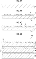
- FIG. 1 is a cross-sectional view schematically showing a first embodiment of a decorative laminate according to the present invention.
- a decorative laminate 100 is formed by laminating a coating layer (hard resin layer) 2 constituted of a hard resin material, a transparent film (transparent base material) 1, a printed layer 3, an adhesive layer 6, a shielding layer 4, an adhesive layer 7, and a core material (core layer) 5 in this order.
- a coating layer (hard resin layer) 2 constituted of a hard resin material, a transparent film (transparent base material) 1, a printed layer 3, an adhesive layer 6, a shielding layer 4, an adhesive layer 7, and a core material (core layer) 5 in this order.
- the upper side in FIG. 1 is the viewpoint side of an observer.
- the decorative laminate 100 includes a transparent film 1, a coating layer 2 constituted of a hard resin material and disposed on a first surface 11 side which is one surface of the transparent film 1, a shielding layer 4 disposed on a second surface 12 side of the transparent film 1, which is a surface opposite to the first surface 11, and a printed layer 3 disposed between the coating layer 2 and the shielding layer 4.
- the decorative laminate 100 includes a transparent film 1 provided with a printed layer 3, a coating layer 2 constituted of a hard resin material and disposed on a first surface 11 side which is one surface of the transparent film 1, and a shielding layer 4 disposed on a second surface 12 side of the transparent film 1, which is a surface opposite to the first surface 11.
- a pattern of the printed layer 3 can be suitably reflected on the external appearance of the decorative laminate 100 while exhibiting the features of the hard resin material such as scratch resistance and antifouling properties, and thus a decorative laminate 100 having excellent aesthetics can be provided.
- excellent aesthetics can be stably exhibited. Accordingly, it is possible to provide a decorative laminate 100 having excellent aesthetics and excellent scratch resistance (difficulty of scratching) and antifouling properties (difficulty of adhesion of stains and ease of stain removal) .
- by providing the printed layer 3 together with the shielding layer 4 it is possible to express various patterns and color tones and to provide a decorative laminate 100 having particularly excellent aesthetics.
- the printed layer 3 is disposed on the second surface 12 side of the transparent film 1.
- the wear resistance of the decorative laminate 100 can be particularly improved.
- the transparent film (transparent base material) 1 has a function of supporting the coating layer 2, the printed layer 3, and the like.
- the transparent film 1 suitably transmits light reflected by the printed layer 3 and the shielding layer 4. That is, the transparent film 1 has sufficient light transmittance so that an observer can visually recognize the transmitted light.
- the transparent film 1 has light transmittance (transparency) at such an extent that the decorative laminate 100 having sufficiently excellent aesthetics can be provided (an extent to which the printed layer 3 and the shielding layer 4 affect the external appearance of the decorative laminate 100).
- the light transmittance for each wavelength in a range of 380 nm or more and 780 nm or less is preferably 80% or more, more preferably 85% or more, and even more preferably 90% or more.
- the transparent film 1 may be constituted of any material as long as the material is a transparent material.
- Examples of the constituent material of the transparent film 1 include various resin materials and various glass materials.
- the transparent film 1 has a configuration containing a resin material (transparent resin film).
- the resin material constituting the transparent film 1 for example, various thermoplastic resins, cured products of curable resin materials, and the like can be used.
- the resin material constituting the transparent film 1 include polyolefins such as polyethylene, polypropylene, ethylene-propylene copolymers, and ethylene-vinyl acetate copolymers (EVA), polyesters such as cyclic polyolefin (COP), modified polyolefin, polyvinyl chloride, polyvinylidene chloride, polystyrene, polyamides (for example, nylon 6, nylon 46, nylon 66, nylon 610, nylon 612, nylon 11, nylon 12, nylon 6-12, and nylon 6-66), polyimide, polyamideimide, polycarbonate (PC), poly-(4-methylpentene-1), ionomers, acrylic resins, polymethylmethacrylate, acrylonitrile-butadiene-styrene copolymers (ABS resins), acrylonitrile-styrene
- the transparent film 1 may contain components other than those components mentioned above.
- Such components include colorants, slip agents (leveling agents), fillers, ultraviolet absorbers, plasticizers, fungicides, preservatives, antioxidants, chelating agents, thickeners, antifoaming agents, and sensitizers (sensitizing dyes) .
- the content of the resin material in the transparent film 1 is preferably 80% by mass or more, more preferably 90% by mass or more, and even preferably 95% by mass or more.
- the transparent film 1 may have a uniform composition in each portion or may have a plurality of portions having different compositions.
- the transparent film 1 may include a base constituted of a material containing polyethylene terephthalate, and an ink receiving layer.
- the stability with respect to a bending external force and the like and the ease of handling can be further improved, the adhesion of the printed layer 3 and the precision of the printed layer 3 can be further improved, and the durability and aesthetics of the decorative laminate 100 can be further improved.
- the thickness of the transparent film 1 is not particularly limited, the thickness is preferably 10 ⁇ m or more and 300 ⁇ m or less, and more preferably 20 ⁇ m or more and 150 ⁇ m or less.
- the thickness of the transparent film 1 is excessively small, the durability of the decorative laminate 100 is deteriorated.
- the properties of the surface of the decorative laminate 100 are greatly affected by the layer (such as the adhesive layer 6) on the inner side of the transparent film 1. As a result, it may be difficult to sufficiently improve the scratch resistance and the like of the decorative laminate 100.
- the coating layer 2 constituted of a hard resin material is provided on the first surface 11 side of the transparent film 1 (the viewpoint side of an observer in a state in which the decorative laminate 100 is placed) .
- the coating layer 2 is formed by using a composition for forming a coating layer containing a hard resin material.
- the hard resin material constituting the coating layer 2 generally has high transparency. Accordingly, the coating layer 2 suitably transmits the light reflected by the printed layer 3 and the shielding layer 4 together with the transparent film 1. Thus, the transmitted light can be visually recognized by an observer, and a decorative laminate 100 having excellent aesthetics can be provided.
- the coating layer 2 also has a function of protecting the printed layer 3, the shielding layer 4, and the like.
- the coating layer 2 may have light transmittance (transparency) to the extent that the decorative laminate 100 having sufficiently excellent aesthetics can be provided (the extent to which the printed layer 3 and the shielding layer 4 affect the external appearance of the decorative laminate 100).
- the light transmittance for each wavelength in a range of 380 nm or more and 780 nm or less is preferably 80% or more, more preferably 85% or more, and even more preferably 90% or more.
- the Martens hardness of the surface of the coating layer 2 is preferably 200 N/mm 2 or more and 800 N/mm 2 or less, and more preferably 300 N/mm 2 or more and 700 N/mm 2 or less.
- the Martens hardness of the surface of the coating layer 2 is less than the lower limit value, the scratch resistance and the like of the coating layer 2 are deteriorated, and thus the decorative laminate 100 is easily scratched.
- the Martens hardness of the surface of the coating layer 2 is more than the upper limit value, the workability of the decorative laminate 100 may be deteriorated.
- the constituent material of the coating layer 2 examples include resin materials such as melamine-based resins, urea-based resins, vinyl chloride-based resins, phenol-based resins, acrylic resins, and urethane-based resins, and inorganic materials such as ceramic-based and glass-based materials.
- the coating layer 2 is preferably constituted of a material containing a melamine-based resin.
- a decorative laminate 100 which has appropriate elasticity and rigidity and has particularly excellent handleability (ease of handling).
- a melamine-based resin has particularly high surface hardness and has particularly excellent scratch resistance and antifouling properties (difficulty of adhesion of stains). Therefore, the melamine-based resin is preferable from the viewpoint of further improving the aesthetics and durability of the decorative laminate 100.
- the coating layer 2 is constituted of a material containing a melamine-based resin will be mainly described.
- the melamine-based resin is a resin containing a melamine compound and an aldehyde compound as constituent components.
- the melamine compound is a compound having a 1,3,5-triazine skeleton and is a compound in which three amino groups are introduced into the triazine ring.
- a preferable structure of the melamine compound is represented by, for example, the following formula (3).
- R 1 , R 2 , and R 3 each independently represent a hydrogen atom or a hydrocarbon group having 1 to 4 carbon atoms which may have a substituent.
- melamine compound a compound (melamine) in which all of R 1 , R 2 , and R3 in the formula (3) represent a hydrogen atom is particularly preferable.
- the hardness of the decorative laminate 100 can be further improved.
- the melamine resin constituting the decorative laminate 100 can be more efficiently synthesized.
- the aldehyde compound may have an aldehyde group (-CHO) in the molecule and is represented by, for example, the following formula (2).
- R represents a hydrogen atom or a hydrocarbon group having 1 to 10 carbon atoms which may have a substituent.
- formaldehyde is particularly preferable.
- the hardness of the decorative laminate 100 can be further improved.
- the melamine resin constituting the decorative laminate 100 can be more efficiently synthesized.
- the melamine-based resin may contain a melamine compound and an aldehyde compound as constituent components.
- the melamine-based resin may further contain a guanamine compound as a constituent component in addition to the melamine compound and the aldehyde compound.
- the workability of the decorative laminate 100 can be particularly improved while the hardness of the decorative laminate 100 is sufficiently improved.
- the guanamine compound is a compound having a 1,3,5-triazine skeleton and is a compound in which two amino groups are introduced into the triazine ring.
- a preferable structure of the guanamine compound is represented by, for example, the following formula (1).
- R represents a hydrogen atom or a hydrocarbon group having 1 to 10 carbon atoms which may have a substituent.
- guanamine compound a compound (acetoguanamine) in which R in the formula (1) is a methyl group is particularly preferable.
- the hardness and workability of the decorative laminate 100 can be achieved at a higher level.
- the melamine resin constituting the decorative laminate 100 can be more efficiently synthesized.
- the melamine resin is not particularly limited.
- a melamine-based resin obtained by allowing a melamine-based compound to react with an aldehyde-based compound in a neutral or weak alkali, and the like can be used.
- reaction molar ratio of the aldehyde-based compound to the melamine-based compound (which is a value of (molar amount of aldehyde-based compound)/(molar amount of melamine-based compound), and hereinafter, sometimes simply referred to as "reaction molar ratio”) is not particularly limited.
- the reaction molar ratio is preferably 1.0 or more and 4.0 or less, more preferably 1.0 or more and 2.0 or less, and even preferably 1.1 or more and 1.8 or less.
- the reaction molar ratio is less than the lower limit value, the amount of unreacted components increases. As a result, the storage properties of the melamine-based resin obtained may be deteriorated and the cost may increase.
- the flexibility of the melamine-based resin after curing may be significantly reduced.
- one melamine-based resin may be used alone, or two or more of melamine-based resins having different reaction molar ratios, weight average molecular weights, and the like may be mixed and used.
- melamine-based resin for example, a commercially available product such as a melamine-based resin manufactured by Sumitomo Chemical Co., Ltd. can be used.
- the coating layer 2 may contain components other than the components described above.
- Such components include inorganic fillers, colorants, slip agents (leveling agents), fillers, ultraviolet absorbers, plasticizers, fungicides, preservatives, antioxidants, chelating agents, thickeners, antifoaming agents, and sensitizers (sensitizing dyes).
- the content of the melamine-based resin in the coating layer 2 is not particularly limited, but is preferably 80% by mass or more and 100% by mass or less, and more preferably 95% by mass or more and 100% by mass or less.
- the thickness of the coating layer 2 is not particularly limited, but is preferably 1 ⁇ m or more and 30 ⁇ m or less, and more preferably 3 ⁇ m or more and 20 ⁇ m or less.
- the scratch resistance and antifouling properties (stain resistance) of the decorative laminate 100 can be particularly improved, and the bending workability and the like of the decorative laminate 100 can also be improved.
- the outer surface (the surface on the side opposite to the surface facing the transparent film 1) side of the coating layer 2 may be subjected to surface finish such as mirror finish or embossing finish.
- the aesthetics of the decorative laminate 100 can be further improved.
- the printed layer 3 is provided on the second surface 12 (the surface opposite to the first surface 11) side of the transparent film 1.
- the printed layer 3 is provided on the outer surface side (viewpoint side of an observer) of the decorative laminate 100 with respect to the shielding layer 4 together with the shielding layer 4 described in detail later.
- a decorative laminate 100 having particularly excellent aesthetics.
- the contrast between the printed layer 3 and the shielding layer 4 can be increased, and the printed layer 3 can be more easily visually recognized.
- a decorative laminate 100 having particularly excellent aesthetics.
- the printed layer 3 is provided on the second surface 12 side of the transparent film 1, the durability of the decorative laminate 100 can be particularly improved.
- the printed layer 3 is usually constituted of a material containing a colorant such as a pigment or a dye.
- the printed layer 3 may contain a resin material in addition to the colorant.
- the adhesion of the printed layer 3 to the transparent film 1 and the like can be improved, and the durability of the decorative laminate 100 can be further improved.
- the decorative laminate 100 is produced, it is possible to more effectively prevent or suppress unintended cissing and wetting and spreading of the ink used for forming the printed layer 3.
- the accuracy of the pattern of the printed layer 3 can be more reliably improved.
- the resin material constituting the printed layer 3 for example, various thermoplastic resins, cured products of curable resin materials, and the like can be used.
- the resin material constituting the printed layer 3 include polyolefins such as polyethylene, polypropylene, ethylene-propylene copolymers, and ethylene-vinyl acetate copolymers (EVA), polyesters such as cyclic polyolefin (COP), modified polyolefin, polyvinyl chloride, polyvinylidene chloride, polystyrene, polyamides (for example, nylon 6, nylon 46, nylon 66, nylon 610, nylon 612, nylon 11, nylon 12, nylon 6-12, and nylon 6-66), polyimide, polyamideimide, polycarbonate (PC), poly-(4-methylpentene-1), ionomers, acrylic resins, polymethylmethacrylate, acrylonitrile-butadiene-styrene copolymers (ABS resins), acrylonitrile-styrene
- the printed layer 3 may contain components other than those components described above.
- Such components include slip agents (leveling agents), fillers, ultraviolet absorbers, plasticizers, dispersants, penetration accelerators, wetting agents (moisturizers), fixing agents, fungicides, preservatives, and antioxidants, chelating agents, thickeners, antifoaming agents, and sensitizers (sensitizing dyes).
- the printed layer 3 may be provided in any pattern, but this pattern is usually determined according to the demand of a consumer.
- Examples of the pattern of the printed layer 3 include wood grain, stone grain, scoring, and various geometric patterns.
- the printed layer 3 is selectively provided on only a part of the second surface 12 of the transparent film 1, but the present invention is not limited thereto.
- the printed layer 3 may be provided over the entire second surface 12 of the transparent film 1 as long as at least a part of the reflected light from the shielding layer 4 can be transmitted.
- the present invention is not limited thereto.
- the interface between the transparent film 1 and the printed layer 3 may be unclear (indistinct) due to dissolution of a part of the transparent film 1 or the like.
- the printed layer 3 may be formed inside the transparent film 1 by the ink penetrating into the transparent film 1 (particularly, the ink receiving layer).
- the shielding layer 4 having shielding properties is provided on the surface side of the printed layer 3 opposite to the surface facing the transparent film 1.
- the shielding layer 4 By providing the shielding layer 4, the state of the back surface side of the shielding layer 4 (the surface on the side opposite to the surface facing the printed layer 3) can be shielded. Accordingly, it is possible to effectively prevent the configuration of the decorative laminate 100 on the back side of the shielding layer 4 and a portion (a wall surface or the like) where the decorative laminate 100 is placed from adversely affecting the external appearance of the decorative laminate 100. As a result, the decorative laminate 100 having a desired external appearance can be reliably obtained.
- the shielding layer 4 is provided on a side (inner side) farther from the viewpoint of an observer than the printed layer 3 in a state in which the decorative laminate 100 is in use, the following effect can be obtained. That is, it is possible to allow an observer to visually recognize the color tone and pattern of the combination of the printed layer 3 and the shielding layer 4. Therefore, it is possible to provide a decorative laminate 100 having particularly excellent aesthetics.
- the shielding layer 4 is provided on the inner side of the coating layer 2, the transparent film 1, and the like, so that the durability of the decorative laminate 100 can be further improved.
- the shielding layer 4 may have a function of shielding (concealing) the back surface side thereof, and the color tone thereof is not particularly limited. However, from the viewpoint of the following effects, the shielding layer 4 preferably exhibits an achromatic color.
- the contrast of the external appearance of the decorative laminate 100 can be improved, and the visibility of the printed layer 3 and the aesthetics of the printed layer 3 or the like can be further improved.
- the achromatic color can exhibit excellent visibility and aesthetics in combination with a wide range of colors, the range of color tone selection of the printed layer 3 is widened.
- the printed layer 3 is accompanied by a delicate change in color tone at each portion, it is easy for an observer to visually recognize such a delicate change in color tone, which is advantageous in that the aesthetics of the decorative laminate 100 is further improved.
- the light transmittance for each wavelength in a range of 380 nm or more and 780 nm or less is preferably 0% or more and 40% or less, more preferably 0% or more and 30% or less, and even more preferably 0% or more and 25% or less.
- the shielding layer 4 may be constituted of any material, and examples of the constituent material of the shielding layer 4 include a resin material, a metal material, and a metal compound such as a metal oxide.
- thermoplastic resins such as polyethylene, polypropylene, ethylene-propylene copolymers, and ethylene-vinyl acetate copolymers (EVA)
- polyesters such as cyclic polyolefin (COP), modified polyolefin, polyvinyl chloride, polyvinylidene chloride, polystyrene, polyamides (for example, nylon 6, nylon 46, nylon 66, nylon 610, nylon 612, nylon 11, nylon 12, nylon 6-12, and nylon 6-66), polyimide, polyamideimide, polycarbonate (PC), poly-(4-methylpentene-1), ionomers, acrylic resins, polymethylmethacrylate, acrylonitrile-butadiene-styrene copolymers (ABS resins), acrylonitrile-styrene copolymers (AS resins), butadiene-st
- ABS resins acrylonitrile-styrene copolymers
- the shielding layer 4 is preferably constituted of a material containing at least polyethylene terephthalate.
- the adhesion of the shielding layer 4 to the adhesive layer 6, the core material 5, and the printed layer 3 can be further improved, and the durability of the decorative laminate 100 can be further improved.
- the shielding layer 4 constituted of a material containing polyethylene terephthalate generally has appropriate flexibility, the workability and ease of handling of the decorative laminate 100 as a whole are improved.
- the shielding layer 4 may contain components other than the above-mentioned components.
- Such components include white pigments such as titanium oxide and zinc oxide; black pigments such as carbon black; other pigments; various dyes; and various metal materials.
- the shielding layer 4 is preferably constituted of a material containing at least one of titanium oxide and zinc oxide in addition to polyethylene terephthalate.
- the durability of the decorative laminate 100 can be improved, and the shielding layer 4 can exhibit white with high brightness or metallic luster.
- the use of the above material is also advantageous from the viewpoint of reducing the production cost of the decorative laminate 100.
- the shielding layer 4 may contain components other than those components described above.
- slip agents leveling agents
- fillers ultraviolet absorbers
- plasticizers plasticizers
- fungicides preservatives
- antioxidants antioxidants
- chelating agents thickeners
- antifoaming agents examples include slip agents (leveling agents), fillers, ultraviolet absorbers, plasticizers, fungicides, preservatives, antioxidants, chelating agents, thickeners, and antifoaming agents.
- the shielding layer 4 may contain a plurality of bubbles.
- the content of polyethylene terephthalate in the shielding layer 4 is not particularly limited, but is preferably 60% by mass or more and 99.5% by mass or less, and more preferably 80% by mass or more and 99% by mass or less.
- the thickness of the shielding layer 4 is not particularly limited, the thickness is preferably 10 ⁇ m or more and 300 ⁇ m or less, and more preferably 20 ⁇ m or more and 200 ⁇ m or less.
- the shielding layer 4 for example, the shielding properties of the shielding layer 4
- the stability with respect to a bending external force and the like and ease of handling can be further improved.
- the shielding layer 4 may have a surface having high flatness.
- the surface of the shielding layer 4 may be subjected to a surface roughening treatment such as embossing, scoring, or blasting.
- the surface roughening treatment may be applied to the surface on the side facing the transparent film 1 or the surface on the side facing the core material 5 (the surface on the side opposite to the surface facing the transparent film 1) or may be applied to both of the surfaces.
- the surface roughening treatment may be performed on the entire target surface, or may be performed on only a part of the surface.
- the above-mentioned shielding layer 4 can also function as a portion where the printed layer 3 is provided, that is, a substrate of the printed layer 3. Even with such a configuration, the shielding layer 4 is disposed on the side (inner side) farther from the viewpoint of an observer than the printed layer 3 in a state in which the decorative laminate 100 is in use. Thus, an observer can suitably visually recognize the color tone and pattern of the combination of the printed layer 3 and the shielding layer 4 and a decorative laminate 100 having particularly excellent aesthetics can be provided.
- the printed layer 3 is provided on the shielding layer 4 (the printed layer 3 is in contact with the shielding layer 4), compared to a case where another configuration is provided between the printed layer and the shielding layer, the pattern of the printed layer 3 has excellent contrast and can be clearly recognized by an observer. As a result, it is possible to provide a decorative laminate 100 having particularly excellent aesthetics.
- the shielding layer 4 preferably includes an ink receiving layer.
- the ink used for forming the printed layer 3 is allowed to suitably permeate into the shielding layer 4 (ink receiving layer), and the adhesion between the printed layer 3 and the shielding layer 4 can be further improved.
- the proportion of the printed layer 3 that is exposed on the surface (the surface facing the transparent film 1) of the shielding layer 4 can be suppressed, and a difference in adhesiveness (adhesiveness via the adhesive layer 6) to the transparent film 1 at each portion in the plane of the shielding layer 4 can be reduced. As a result, the reliability of the decorative laminate 100 can be further improved.
- the shielding properties of the shielding layer 4 can be improved. Accordingly, it is possible to effectively prevent unintended changes in the physical properties of the shielding layer 4 by incorporating a colorant in the shielding layer 4 (particularly, incorporating a colorant at the relatively high content), and to easily obtain a shielding layer 4 having desired physical properties.
- the ink receiving layer may have void portions.
- the void portion may be provided, for example, as a gap between a plurality of particles as a constituent component constituting the ink receiving layer.
- the void portions are preferably formed by foaming.
- the ink used for forming the printed layer 3 is allowed to more suitably permeate into the shielding layer 4 (ink receiving layer), and the adhesion between the printed layer 3 and the shielding layer 4 can be further improved.
- the porosity (volume ratio occupied by the void portions) in the ink receiving layer is not particularly limited, but is preferably 5% by volume or more and 60% by volume or less, more preferably 10% by volume or more and 55% by volume or less, and even more preferably 15% by volume or more and 50% by volume or less.
- the average diameter of the holes is preferably 10 nm or more and 10 ⁇ m or less, more preferably 20 nm or more and 7 ⁇ m or less, and even more preferably 30 nm or more and 5 ⁇ m or less.
- the effect described above is more remarkably exhibited, the ink absorbency can be further improved, and the formation efficiency of the printed layer 3 (the productivity of the decorative laminate 100) can be further improved.
- the constituent material of the ink receiving layer (substantial portion) is not particularly limited, but various resin materials such as various thermoplastic resins, and cured products of curable resin materials are preferable.
- resin material constituting the ink receiving layer (substantial portion) include polyolefins such as polyethylene, polypropylene, ethylene-propylene copolymers, and ethylene-vinyl acetate copolymers (EVA), polyesters such as cyclic polyolefin (COP), modified polyolefin, polyvinyl chloride, polyvinylidene chloride, polystyrene, polyamides (for example, nylon 6, nylon 46, nylon 66, nylon 610, nylon 612, nylon 11, nylon 12, nylon 6-12, and nylon 6-66), polyimide, polyamideimide, polycarbonate (PC), poly-(4-methylpentene-1), ionomers, acrylic resins, polymethylmethacrylate, acrylonitrile-butadiene-styrene copolymers
- the content of the resin material in the ink receiving layer is not particularly limited, but is preferably 90% by mass or more and 99.5% by mass or less, and more preferably 95% by mass or more and 99% by mass or less.
- the thickness of the ink receiving layer is not particularly limited, but is preferably 20 nm or more and 50 ⁇ m or less, more preferably 30 nm or more and 40 ⁇ m or less, and even more preferably 40 nm or more and 30 ⁇ m or less.
- the base of the shielding layer 4 is preferably constituted of a material including polyethylene terephthalate.
- the base of the shielding layer 4 may contain components other than the resin material.
- components include colorants, slip agents (leveling agents), fillers, ultraviolet absorbers, plasticizers, fungicides, preservatives, antioxidants, chelating agents, thickeners, antifoaming agents, and sensitizers (sensitizing dyes).
- the content of the resin material in the base is not particularly limited, but is preferably 90% by mass or more and 99.5% by mass or less, and more preferably 95% by mass or more and 99% by mass or less.
- the thickness of the base is not particularly limited, but is preferably 30 nm or more and 260 ⁇ m or less, more preferably 70 nm or more and 210 ⁇ m or less, and even more preferably 110 nm or more and 170 ⁇ m or less.
- the adhesive layer (first adhesive layer) 6 having a function of bonding the transparent film 1 provided with the printed layer 3 and the shielding layer 4 is provided between the transparent film and the shielding layer.
- the adhesion between the transparent film 1 provided with the printed layer 3 and the shielding layer 4 can be improved, and the durability of the decorative laminate 100 can be improved.
- the decorative laminate 100 can be produced under relatively mild production conditions (temperature, pressure, and the like) . Therefore, it is possible to effectively prevent unintended deterioration of the constituent material of the decorative laminate 100 and improve the reliability of the decorative laminate 100, and it is also advantageous from the viewpoint of production equipment, production cost, energy saving, and the like. Further, the decorative laminate 100 can be more easily produced, and the productivity of the decorative laminate 100 can be improved.
- Examples of the adhesive constituting the adhesive layer 6 include acrylic adhesives, urethane-based adhesives, silicone-based adhesives, thermoplastic polyimide adhesives such as polyimide, polyimide amide, polyimide amide ether, polyester imide, and polyimide ether, various hot melt adhesives (polyester-based and modified olefin-based adhesives), polyvinyl acetate (VA), and polyethylene vinyl acetate (EVA)-based adhesives.
- acrylic adhesives urethane-based adhesives, silicone-based adhesives, thermoplastic polyimide adhesives such as polyimide, polyimide amide, polyimide amide ether, polyester imide, and polyimide ether, various hot melt adhesives (polyester-based and modified olefin-based adhesives), polyvinyl acetate (VA), and polyethylene vinyl acetate (EVA)-based adhesives.
- the adhesive layer 6 may be a solid content of the thermoplastic resin emulsion.
- the adhesion between the transparent film 1 provided with the printed layer 3 and the shielding layer 4 can be particularly improved.
- the durability of the decorative laminate 100 can be particularly improved, and the workability of the decorative laminate 100 can be particularly improved.
- thermoplastic resin emulsion means a raw material which is in an emulsion state by dispersing the thermoplastic resin in a solvent.
- the solid content of the thermoplastic resin emulsion means a component obtained by removing the solvent from the thermoplastic resin emulsion.
- the solid content of the thermoplastic resin emulsion includes a component present as emulsion resin particles, has adhesive properties with various materials (various resin materials, colorants, and the like), and imparts flexibility to the decorative laminate 100.
- the adhesion adheresive strength
- the transparent film 1 provided with the printed layer 3 and the shielding layer 4 can be improved, and the bending workability of the decorative laminate 100 can be improved.
- the solid content of the thermoplastic resin emulsion is not particularly limited, and examples thereof include emulsion particles of thermoplastic resins such as acrylic resins, urethane resins, vinyl acetate-based copolymers, urethane-acrylic composite particles, styrene-butadiene rubber (SBR), and nitrile rubber (NBR). Among these, urethane-acrylic composite particles are preferable.
- the urethane-acrylic composite particles mean particles having a heterogeneous phase structure of acrylic resin and urethane resin in a single particle thereof.
- urethane resin and the acrylic resin has a high adhesive strength with respect to the transparent film 1, the shielding layer 4, and the core layer 5 described later. Therefore, by using the urethane-acrylic composite particles, good adhesive strength with the transparent film 1, the shielding layer 4, and the core layer 5 can be exhibited. Further, urethane resin has particularly excellent toughness, elasticity, and flexibility, and acrylic resin has particularly excellent transparency, durability, weather resistance, chemical resistance, and film formability.
- the "heterogeneous phase structure” means a structure in which a plurality of phases are present that are formed of different types of resins within a single particle, and examples thereof include a core-shell structure, a local structure, and a sea-island structure.
- the arrangement state of a plurality of urethane-acrylic composite particles in the adhesive layer 6 is not particularly limited, and examples thereof include a linear structure.
- the particle structure and inter-particle arrangement can be confirmed with, for example, a scanning electron microscope (SEM) .
- the above-mentioned urethane-acrylic composite particles are particularly preferable as an aqueous clear type having a core-shell structure having an acrylic component as a core and a urethane component as a shell.
- the surface exterior portion of the adhesive layer 6 has a urethane composition. Therefore, the adhesive layer 6 has the properties of both the urethane resin and the acrylic resin while the properties of the urethane resin are imparted to the exterior portion.
- aqueous clear means an aqueous resin solution in which the resin liquid is water-soluble while the coated film obtained after evaporating the moisture is non-water-soluble, and has transparency to a degree that the color and pattern of the substrate can be clearly distinguished.
- the urethane-acrylic composite particles are the aqueous clear type, it is possible to more effectively prevent and suppress the adverse effect of the adhesive layer 6 on the external appearance of the decorative laminate 100.
- thermoplastic resin emulsion In the solid content of the thermoplastic resin emulsion, one of the thermoplastic resins mentioned above can be used alone, or two or more different thermoplastic resins can be mixed and used.
- the solid content of the thermoplastic resin emulsion may also contain a small amount of a thickener, a penetration accelerators, an antifoaming agent, and the like as necessary.
- the solid content of the thermoplastic resin emulsion preferably contains emulsion resin particles having an average particle diameter of 30 nm or more and 10 ⁇ m or less, and the average particle size of the emulsion resin particles is more preferably 60 nm or more and 5 ⁇ m or less.
- the adhesion between the transparent film 1 provided with the printed layer 3 and the shielding layer 4 can be further improved, the flexibility of the decorative laminate 100 can be further improved.
- the average particle diameter refers to a volume-based average particle diameter unless otherwise specified.
- the particle diameter can be measured by subjecting the target particles in water to an ultrasonic treatment for 1 minute using a laser diffraction particle size distribution analyzer SALD-7000 (manufactured by Shimadzu Corporation) and dispersing the target particles in water.
- SALD-7000 laser diffraction particle size distribution analyzer
- thermoplastic resin emulsion is preferably non-water-soluble.
- thermoplastic resin emulsion containing water as a dispersion medium can be suitably used. As a result, it is possible to reduce the production cost of the decorative laminate 100 and the load on the environment.
- non-water-soluble means that the solubility in water is less than 0.5 g/100 g water at 25°C
- water-soluble means that the solubility in water is 0.5 g/100 g water or more at 25°C.
- the decorative laminate 100 of the embodiment further includes a core material (core layer) 5 on the surface side of the shielding layer 4 opposite to the surface facing the printed layer 3.
- the shape stability, heat resistance, and durability of the decorative laminate 100 can be particularly improved.
- the core material (core layer) 5 is constituted of, for example, a chemical fiber base material.
- the core layer 5 may be constituted of a phenolic resin, a metal material, or the like.
- the material (material) of the chemical fiber base material used for the core layer 5 is not particularly limited, and examples thereof include synthetic fibers, semi-synthetic fibers, regenerated fibers, and inorganic fibers. More specific examples of the material of the chemical fiber base material used for the core layer 5 include polyamide-based resin fibers such as a polybenzoxazole resin fiber, a polyamide resin fiber, an aromatic polyamide resin fiber, and a wholly aromatic polyamide (aramid) resin fiber, polyester resin fibers such as a polyester resin fiber, an aromatic polyester resin fiber, and a wholly aromatic polyester resin fiber, polyimide resin fibers, fluororesin fibers, glass fibers, carbon fibers, ceramic fibers, and metal fibers (stainless fibers).
- polyamide-based resin fibers such as a polybenzoxazole resin fiber, a polyamide resin fiber, an aromatic polyamide resin fiber, and a wholly aromatic polyamide (aramid) resin fiber
- polyester resin fibers such as a polyester resin fiber, an aromatic polyester resin fiber
- the core layer 5 preferably contains glass fibers.
- the shape stability, heat resistance, and durability of the decorative laminate 100 can be further improved.
- the core layer 5 containing glass fibers is not particularly limited, and examples thereof include a glass cloth, and a glass nonwoven fabric. Among these, a glass cloth is preferable from the viewpoint of non-combustibility and strength.
- the glass cloth is not particularly limited, and examples thereof include plain weave, twill weave, satin weave, leno weave, imitation weave, twill weave, and double weave. Among these, a plain weave glass cloth is preferable from the viewpoint of material cost and workability.
- glass constituting the glass cloth examples include E glass, C glass, A glass, S glass, D glass, NE glass, T glass, and H glass.
- the coefficient of thermal expansion of the glass cloth can be lowered.
- the production cost of the decorative laminate 100 can be further reduced while a sufficient function is secured.
- the weight of the glass cloth is not particularly limited, the weight of the aforementioned glass cloth is preferably a basis weight of 80 g/m 2 or more in a case it is necessary to satisfy non-combustibility compatibility requirements of Article 2, Item 9 of the Building Standard Law which states that "non-combustible materials must not contain cracks or holes following combustion".
- the upper limit of weight is preferably a basis weight of 250 g/m 2 or less from the viewpoint of material cost and workability.
- the core layer 5 may be a prepreg having a glass cloth as a base material as described above.
- the heat resistance, rigidity, and the like of the decorative laminate 100 can be particularly improved.
- the prepreg is not particularly limited, and for example, the prepreg can be obtained by impregnating the above-mentioned glass cloth with a resin composition containing a thermoplastic resin, a thermosetting resin, or the like.
- the content of the resin composition contained in the prepreg is not particularly limited as long as the interlayer adhesive strength between the shielding layer 4 and the core layer 5 is sufficient for forming the decorative laminate 100.
- the solid content of the prepreg is preferably 1% by mass or more and 20% by mass or less, and more preferably 1% by mass or more and 10% by mass or less.
- the solid content in the prepreg is preferably 1% by mass or more and 20% by mass or less, and more preferably 2% by mass or more and 10% by mass or less.
- thermoplastic resin examples include an acrylic resin, an urethane resin, an ethylene vinyl acetate resin, and a styrene-butadiene rubber (SBR).
- an acrylic resin and an urethane resin are preferably used.
- thermosetting resin examples include a phenol resin, an epoxy resin, an oxetane resin, a (meth)acrylate resin, an unsaturated polyester resin, a diallyl phthalate resin, a urea resin, and a maleimide resin.
- a phenol resin is preferable from the viewpoint of non-combustibility, heat resistance, and adhesion. These resins may be used alone or in combination of two or more thereof.
- the prepreg can be produced by a conventionally known method.
- a prepreg is obtained by impregnating a glass cloth similar to the glass cloth described above with a varnish obtained by dissolving the resin in a solvent followed by drying.
- the core layer 5 may have a structure in which a plurality of layers are laminated.
- a core layer 5 is obtained as follows, for example. First, fibrous base materials (for example, base materials constituted of paper such as kraft paper) are impregnated with a phenolic resin to obtain a plurality of members . Next, the core layer 5 can be obtained by laminating and bonding the plurality of members.
- Examples of the metal material used for the core layer 5 include iron (Fe), aluminum (Al), zinc (Zn), nickel (Ni), bismuth (Bi), copper (Cu), silver (Ag), gold (Au), platinum (Pt), and alloys containing at least one of these metal materials.
- iron Fe
- aluminum Al
- zinc Zn
- nickel Ni
- bismuth Bi
- copper Cu
- silver Ag
- gold Au
- platinum Pt
- alloys containing at least one of these metal materials aluminum is preferable.
- the non-combustibility of the decorative laminate 100 can be particularly improved.
- the use of the metal material is advantageous.
- the thickness of the core layer 5 is preferably 80 ⁇ m or more.
- the upper limit of the thickness of the core layer 5 is not particularly limited. However, as the thickness of the core layer 5 increases, the thickness and weight of the decorative laminate 100 increase and the cost also increases. Therefore, it is preferable to set the thickness of the core layer 5 in an allowable range in the design of the final product. From such a viewpoint, the thickness of the core layer 5 is more preferably 500 ⁇ m or less.
- the adhesive layer (second adhesive layer) 7 having a function of bonding the shielding layer 4 and the core layer 5 is provided between the shielding layer 4 and the core layer 5.
- the adhesion between the shielding layer 4 and the core layer 5 can be improved, and the durability of the decorative laminate 100 can be improved.
- the decorative laminate 100 can be produced under relatively mild production conditions (temperature, pressure, and the like). Therefore, it is possible to effectively prevent unintended deterioration of the constituent material of the decorative laminate 100 and improve the reliability of the decorative laminate 100, and it is also advantageous from the viewpoint of production equipment, production cost, energy saving, and the like. Further, the decorative laminate 100 can be more easily produced, and the productivity of the decorative laminate 100 can be improved.
- the adhesive layer 7 preferably satisfies the same conditions as those described above for the adhesive layer 6, but the adhesive layer 7 and the adhesive layer 6 do not have to satisfy the same conditions.
- the decorative laminate 100 has a total thickness (average thickness) of preferably 0.1 mm or more and 2 mm or less, and more preferably 0.1 mm or more and 1.2 mm or less.
- the decorative laminate 100 having sufficient strength and particularly excellent workability and handleability.
- FIG. 2 is a cross-sectional view schematically showing a second embodiment of the decorative laminate according to the present invention.
- differences from the above-described embodiment will be mainly described, and the description of the same will be omitted.
- a coating layer (hard resin layer) 2 constituted of a hard resin material, a printed layer 3, a transparent film (transparent base material) 1, and an adhesive layer 6, a shielding layer 4, an adhesive layer 7, and a core material (core layer) 5 are laminated in this order.
- the printed layer 3 is disposed on the second surface 12 side of the transparent film 1 in the decorative laminate 100 of the above-described embodiment, in the decorative laminate 100 of the embodiment, the printed layer 3 is disposed on the first surface 11 side of the transparent film 1.
- the printed layer 3 is disposed on a side closer to the viewpoint of an observer, and the color and pattern of the printed layer 3 becomes clearer. Therefore, it is possible to provide the decorative laminate 100 having further excellent aesthetics. Further, the transparent film 1 having a predetermined thickness is interposed between the printed layer 3 and the shielding layer 4. Due to the printed layer 3 and the shielding layer 4 as described above, it is possible to give a feeling of depth to the external appearance of the decorative laminate 100, and to provide the decorative laminate 100 having an external appearance full of a three-dimensional effect.
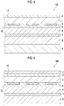
- FIG. 7 is a cross-sectional view schematically showing a third embodiment of the decorative laminate according to the present invention.
- differences from the above-described embodiment will be mainly described, and the description of the same will be omitted.
- a coating layer (hard resin layer) 2 constituted of a hard resin material, a transparent film (transparent base material) 1, a printed layer 3, a gap layer 6, a shielding layer 4, an adhesive layer 7, and a core material (core layer) 5 are laminated in this order.
- the decorative laminate 100 includes a transparent film 1, a coating layer 2 constituted of a hard resin material and disposed on a first surface 11 side, which is one surface of the transparent film 1, a printed layer 3 provided on a second surface 12 side of the transparent film 1, which is a surface opposite to the first surface 11, a shielding layer 4 provided on a surface side opposite to the surface of the printed layer 3 facing the transparent film 1, and a gap layer 6 provided between the printed layer 3 and the shielding layer 4.
- the gap layer 6 having a function of providing a predetermined gap between the printed layer 3 and the shielding layer 4 is provided between the transparent film 1 provided with the printed layer 3 and the shielding layer 4.
- the gap layer 6 may have a function of providing a predetermined gap between the printed layer 3 and the shielding layer 4, but the gap layer 6 is preferably an adhesive layer for bonding the transparent film 1 provided with the printed layer 3 and the shielding layer 4. That is, the gap layer 6 is preferably constituted of a cured product of an adhesive.
- the gap layer may not have a function as an adhesive layer.
- an adhesive layer may be provided between the transparent film 1, the gap layer 6, and the shielding layer 4.
- a gap length L from the surface of the printed layer 3 to the surface of the shielding layer 4 in a case of being observed from the coating layer 2 side is 1 ⁇ m or more and 50 ⁇ m or less. That is, the gap length L from the surface of the printed layer 3 facing the transparent film 1 to the surface of the shielding layer 4 facing the transparent film 1 is preferably 1 ⁇ m or more and 50 ⁇ m or less.
- the pattern of the printed layer 3 can be suitably reflected on the external appearance of the decorative laminate 100 while exhibiting the features of the hard resin material, such as scratch resistance and antifouling properties, and thus a decorative laminate 100 having excellent aesthetics can be provided.
- excellent aesthetics can be stably exhibited. Accordingly, it is possible to provide a decorative laminate 100 having excellent aesthetics and excellent scratch resistance (difficulty of scratching) and antifouling properties (difficulty of adhesion of stains and ease of stain removal).
- the printed layer 3 together with the shielding layer 4, it is possible to express various patterns and color tones and to provide a decorative laminate 100 having particularly excellent aesthetics.
- the gap layer 6 having a predetermined gap length L, it is possible to obtain a decorative laminate 100 having an excellent external appearance full of a three-dimensional effect.
- the following effect can also be obtained. That is, even in a case where the coating layer 2 is worn due to friction, it is possible to prevent the printed layer 3 from being damaged and to maintain an excellent external appearance. In other words, it can be said that the decorative laminate 100 satisfying the above conditions has sufficiently excellent wear resistance.
- the shielding layer 4 is not provided, the visibility of the printed layer 3 and the aesthetics of the decorative laminate 100 may be deteriorated depending on the substrate of the decorative laminate 100.
- the gap length from the surface of the printed layer 3 to the surface of the shielding layer 4 is less than the lower limit value, the adhesion between the transparent film 1 provided with the printed layer 3 and the shielding layer 4 is decreased. As a result, it is not possible to provide a decorative laminate 100 having sufficiently excellent durability. Further, the three-dimensional effect of the pattern of the printed layer 3 is reduced, and thus a decorative laminate 100 having sufficiently excellent aesthetics cannot be provided.
- the gap length from the surface of the printed layer 3 to the surface of the shielding layer 4 is more than the upper limit value, the strength of the decorative laminate 100 against indentation deformation cannot be maintained. As a result, it is not possible to provide a decorative laminate 100 having sufficiently excellent durability. In addition, the impression that the pattern of the printed layer 3 is unnaturally raised may be given to an observer, and the aesthetics of the decorative laminate 100 may be deteriorated.
- the gap length L is preferably 1 ⁇ m or more and 50 ⁇ m or less, more preferably 3 ⁇ m or more and 30 ⁇ m or less, and particularly preferably 10 ⁇ m or more and 20 ⁇ m or less.
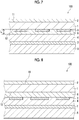
- FIG. 8 is a sectional view schematically showing a fourth embodiment of the decorative laminate according to the present invention.
- differences from the above-described embodiment will be mainly described, and the description of the same will be omitted.
- a coating layer (hard resin layer) 2 constituted of a hard resin material, a transparent film (transparent base material) 1, an adhesive layer 6, a shielding layer 4 provided with a printed layer 3, an adhesive layer 7, and a core material (core layer) 5 are laminated in this order.
- the decorative laminate 100 includes a transparent film 1, a coating layer 2 constituted of a hard resin material and disposed on a first surface 11 side, which is one surface of the transparent film 1, a shielding layer 4 provided on a second surface 12 side of the transparent film 1, which is a surface opposite to the first surface 11, a printed layer 3 provided on a surface of the shielding layer 4 facing the transparent film 1, and an adhesive layer 6 provided between the transparent film 1 and the shielding layer 4 provided with the printed layer 3.
- the decorative laminate 100 while exhibiting the features of the hard resin material, such as scratch resistance (difficulty of scratching) and antifouling properties, regardless of the construction portion of the decorative laminate 100 (the substrate of the decorative laminate 100), it is possible to suitably reflect the pattern of the printed layer 3 on the external appearance of the decorative laminate 100 and to provide a decorative laminate 100 that can stably exhibit excellent aesthetics.
- the pattern of the printed layer 3 has excellent contrast and is clearly recognized by an observer. As a result, it is possible to provide a decorative laminate 100 having particularly excellent aesthetics.
- the shielding layer 4 provided with the printed layer 3 is bonded to the transparent film 1 by the adhesive layer 6. Therefore, unintended peeling between the printed layer 3 and the transparent film 1 is effectively prevented. Accordingly, it is possible to provide a decorative laminate 100 having excellent aesthetics and excellent durability and antifouling properties (difficulty of adhesion of stains and ease of stain removal) . In addition, by providing the printed layer 3 together with the shielding layer 4, it is possible to express various patterns and color tones and to provide a decorative laminate 100 having particularly excellent aesthetics. Further, since the transparent film 1 not having an ink receiving layer can be suitably used and a so-called mat type sheet can be used as the shielding layer 4, the thickness of the decorative laminate 100 can be reduced.
- the printed layer 3 is selectively provided on only a part of the surface of the shielding layer 4 facing the transparent film 1, but the present invention is not limited thereto.
- the printed layer 3 may be provided over the entire surface of the shielding layer 4 facing the transparent film 1 as long as at least a part of the reflected light from the shielding layer 4 can be transmitted.
- the printed layer 3 is formed by impregnation of the inside of the shielding layer 4 (ink receiving layer), but the present invention is not limited thereto.
- the printed layer 3 may be carried on the surface of the shielding layer 4.
- FIGS. 3A to 3D are cross-sectional views showing a first embodiment of the method for producing the decorative laminate of the present invention.
- the production method of the embodiment has a transparent film preparation step (3A) of preparing a transparent film 1, a printing step (3B) of forming a printed layer 3 on one surface (second surface 12) of the transparent film 1, a coating layer formation step (3C) of forming a coating layer 2 on the other surface (first surface 11) of the transparent film 1, and a bonding step (3D) of bonding the transparent film 1 provided with the printed layer 3 and a shielding layer 4 by forming an adhesive layer 6 on one surface of the shielding layer 4, and bonding the shielding layer 4 and a core layer 5 by forming an adhesive layer 7 on the other surface of the shielding layer 4 (a surface on the side opposite to the surface facing the transparent film 1).
- a transparent film 1 as described above is prepared (3A).
- the transparent film 1 for example, a film having an area corresponding to a decorative laminate 100 to be produced can be used.
- a long film wound in a roll shape can be used.
- the film may be cut into a predetermined length during or after this step.
- the transparent film 1 prepared in this step may include an ink receiving layer that absorbs the ink used for forming the printed layer 3 on the second surface 12, for example.
- the second surface 12 of the transparent film 1 prepared in this step may be subjected to various surface treatments (surface activation treatments) such as a plasma treatment, an ultraviolet irradiation treatment, and a primer treatment, before the subsequent printing step.
- various surface treatments such as a plasma treatment, an ultraviolet irradiation treatment, and a primer treatment
- the transparent film 1 it is possible to particularly improve the adhesion between the transparent film 1 and a layer provided on the transparent film 1 (for example, the printed layer 3 or the shielding layer 4 via the adhesive layer 6).
- the first surface 11 of the transparent film 1 may be subjected to the same surface treatment as described above before the subsequent coating layer formation step.
- the adhesion between the transparent film 1 and the coating layer 2 can be particularly improved.
- the ink can be applied to the transparent film 1 by various printing methods such as an ink jet method, a screen printing method, a gravure printing method, and a pad printing method.
- the preparation of a plate becomes unnecessary, and printed layers 3 of various patterns can be suitably formed in a short period of time. Therefore, it is possible to suitably provide various decorative laminates 100.
- an ink containing a component (a solvent or the like) that dissolves or swells a part of the transparent film 1 (a region near the surface where the ink is applied) may be used.
- the applied ink can be suitably attached to a target portion of the transparent film 1, and cissing and excessive wetting and spreading of the ink on the transparent film 1 can be effectively prevented.
- the printed layer 3 having a desired pattern can be easily and reliably formed.
- the adhesion of the printed layer 3 to the transparent film 1 can be improved, and the durability of the finally obtained decorative laminate 100 can be particularly improved.
- the color reproduction range can be expanded, and delicate gradation expression can be more suitably performed.
- the ink used for forming the printed layer 3 will be described in detail later.
- the coating layer 2 is formed on the surface (first surface 11) side opposite to the surface (second surface 12) of the transparent film 1 on which the printed layer 3 is provided (3C) .
- the coating layer 2 is formed as follows, for example. That is, a composition for forming a coating layer is applied to the first surface 11 side of the transparent film 1 by various methods such as a dipping method, a spray method, coating methods using various coaters such as a kiss coater, a comma coater, a roll coater, a knife coater, and a blade coater, and various printing methods. Thereafter, by conducting a curing reaction, the coating layer 2 can be suitably formed on the first surface 11.
- composition used for forming the coating layer 2 (composition for forming a coating layer) will be described in detail later.
- the coating layer 2 may be formed by bonding a member for forming a coating layer formed into a sheet shape to the first surface 11 side of the transparent film 1.
- the member for forming a coating layer and the transparent film 1 can be bonded by, for example, pressure bonding.
- the bonding between the member for forming a coating layer and the transparent film 1 may be performed by, for example, heating the transparent film 1 and the member for forming a coating layer during the pressure bonding.
- the productivity of the decorative laminate 100 can be particularly improved, and the bonding strength between the transparent film 1 and the coating layer 2 can be particularly improved.
- the polymerization reaction of the components contained in the coating layer 2 can be allowed to suitably proceed. Therefore, the hardness of the coating layer 2 and the durability and reliability of the decorative laminate 100 can be particularly improved.
- a mirror-finished plate is superposed on the outer surface of the member for forming a coating layer (the surface on the side opposite to the surface facing the transparent film 1) to perform mirror finish.
- embossing finish can be performed by superposing an embossing plate, an embossing film, or the like on the outer surface side of the member for forming a coating layer.
- the polymerization reaction of the coating layer 2 formed in this step may not be completed. Even in such a case, the polymerization reaction of the constituent components of the coating layer 2 can be allowed to proceed in the subsequent step, and the durability, reliability, and the like of the finally obtained decorative laminate 100 can be particularly improved.
- the adhesive layer 6 is formed on one surface of the shielding layer 4, and the transparent film 1 provided with the printed layer 3 and the shielding layer 4 are bonded.
- the adhesive layer 7 is formed on the other surface of the shielding layer 4 (the surface opposite to the surface facing the transparent film 1) and the shielding layer 4 and the core material (core layer) 5 are bonded (3D).
- the shielding layer 4 is constituted of the above-mentioned material, and can be formed using, for example, a white polyethylene terephthalate film (white PET film).
- the adhesive layer 6 can be suitably formed by applying a composition for forming an adhesive layer to at least one of the transparent film 1 provided with the printed layer 3 and the shielding layer 4 by various methods such as a dipping method, a spray method, coating methods using various coaters such as a kiss coater, a comma coater, a roll coater, a knife coater, and a blade coater, and various printing methods.
- the adhesive layer 7 can be suitably formed on at least one of the core layer 5 and the shielding layer 4 by the same method as the method for forming the adhesive layer 6.
- the core layer 5 and the shielding layer 4 can be bonded by, for example, in a case where the core layer 5 contains a resin material, melting and softening a part of the core layer 5.
- the core layer 5 and the shielding layer 4 may be bonded by, for example, adhesion.
- the decorative laminate 100 can be produced by omitting a part of the above-described bonding step (core layer formation step).
- FIGS. 4A to 4D are cross-sectional views showing a second embodiment of the method for producing the decorative laminate according to the present invention.
- differences between the production method described above and the first embodiment will be mainly described, and the description of the same will be omitted.
- the production method of the embodiment has a transparent film preparation step (4A) of preparing a transparent film 1, a printing step (4B) of forming a printed layer 3 on one surface (first surface 11) of the transparent film 1, a coating layer formation step (4C) of forming a coating layer 2 on the surface of the transparent film 1 on which the printed layer 3 is provided, and a bonding step (4D) of bonding the transparent film 1 provided with the printed layer 3 and a shielding layer 4 by forming an adhesive layer 6 on one surface of the shielding layer 4, and bonding the shielding layer 4 and a core layer 5 by forming an adhesive layer 7 on the other surface of the shielding layer 4 (a surface on the side opposite to the surface facing the transparent film 1).
- the printed layer 3 is formed on the second surface 12 of the transparent film 1 in the production method of the first embodiment described above, the printed layer 3 is formed on the first surface 11 of the transparent film 1 in the manufacturing method of the embodiment.
- the differences from the first embodiment of the production method described above will be mainly described, and the description of the same will be omitted. While the adhesive layer 6 is formed on the surface of the shielding layer 4 in the first embodiment of the production method described above, the gap layer 6 is formed on the surface of the shielding layer 4 instead of the adhesive layer 6 in the embodiment. Thus, the decorative laminate 100 according to the third embodiment described above can be produced.
- FIGS. 9A to 9C are cross-sectional views showing a fourth embodiment of the method for producing the decorative laminate according to the present invention.
- differences from the embodiment of the production method described above will be mainly described, and the description of the same will be omitted.
- the production method of the embodiment has a printing step (9A) of forming a printed layer 3 on one surface of a shielding layer 4, a coating layer formation step (9B) of forming a coating layer 2 on one surface (first surface 11) of a transparent film 1, and a bonding step (9C) of bonding the transparent film 1 having the coating layer formed thereon and the shielding layer 4 provided with the printed layer 3 by forming an adhesive layer 6 on one surface of the shielding layer 4, and bonding a core layer 5 and the shielding layer 4 by forming an adhesive layer 7 on the other surface of the shielding layer 4.
- the printing step (9A) of forming the printed layer 3 on one surface of the shielding layer 4 will be described in detail.
- an ink is applied to one surface of the shielding layer 4 to form the printed layer 3 (9A).
- the shielding layer 4 for example, a film having an area corresponding to a decorative laminate 100 to be produced can be used.
- a long sheet wound in a roll shape can be used. Note that the sheet may be cut into a predetermined length during or after this step.
- the shielding layer 4 used in this step may include, for example, an ink receiving layer that absorbs the ink used for forming the printed layer 3.
- the printed layer 3 can be formed inside the shielding layer 4. As a result, it is possible to more reliably exhibit the above-described effects (to provide a decorative laminate 100 having excellent aesthetics, durability, and antifouling properties).
- the surface of the shielding layer 4 used in this step, on which the printed layer 3 is formed is subjected to various surface treatments (surface activation treatments) such as a plasma treatment, an ultraviolet irradiation treatment, and a primer treatment, before printing.
- various surface treatments such as a plasma treatment, an ultraviolet irradiation treatment, and a primer treatment, before printing.
- the adhesion between the shielding layer 4 and the printed layer 3 and the adhesion between the shielding layer 4 and the transparent film 1 can be particularly improved.
- the surface of the shielding layer 4 on the side opposite to the surface on which the printed layer 3 is formed may be subjected to the same surface treatment as described above.
- the adhesion between the shielding layer 4 and the core material 5 (the adhesion with the shielding layer 4 via the adhesive layer 7) can be particularly improved.
- the ink can be applied to the shielding layer 4 in the same manner as in the application of the ink to the transparent film 1 in the first embodiment of the production method described above by various printing methods such as an ink jet method, a screen printing method, a gravure printing method, and a pad printing method.
- the preparation of a plate becomes unnecessary, and printed layers 3 of various patterns can be suitably formed in a short period of time. Therefore, it is possible to suitably provide various decorative laminates 100.
- the color reproduction range can be expanded, and delicate gradation expression can be more suitably performed.
- the ink used for forming the printed layer 3 usually contains a colorant.
- the ink usually contains a colorant as a solid content.
- colorant for example, various pigments and various dyes can be used, and fluorescent materials, phosphorescent materials, and the like can also be used. Among these, it is preferable to use an ink containing a pigment as a colorant.
- the durability of the decorative laminate 100 can be particularly improved.
- inks corresponding to three primary colors cyan (indigo purple), magenta (red purple), and yellow
- cyan indigo purple
- magenta red purple
- yellow yellow
- a black ink may be used in combination with a chromatic color ink.
- a white ink may be used.
- the contrast and the like of the printed layer 3 formed of a chromatic ink can be particularly improved, and the decorative laminate 100 having particularly excellent aesthetics can be provided.
- indigo purple pigment ink exhibiting indigo purple (cyan) it is preferable to use one or two or more pigments selected from the group consisting of C.I. Pigment Blue 15: 3, C.I. Pigment Blue 15: 2, and C.I. Pigment Blue 60 as a pigment constituting the ink.
- a red purple (magenta) pigment ink exhibiting magenta it is preferable to use one or two or more pigments selected from the group consisting of C.I. Pigment Violet 19, C.I. Pigment Red 122, and C.I. Pigment Violet 37 as a pigment constituting the ink.
- a yellow pigment ink exhibiting yellow it is preferable to use one or two or more pigments selected from the group consisting of C.I. Pigment Yellow 150, C.I. Pigment Yellow 138, and C.I. Pigment Yellow 139 as a pigment forming the ink.
- C.I. Pigment Red 177 and/or C.I. Pigment Red 254 as a pigment constituting the ink.
- C.I. Pigment Green 36 and/or C.I. Pigment Green 58 as a pigment constituting the ink.
- C.I. Pigment Blue 15: 6 it is preferable to use C.I. Pigment Blue 15: 6 as a pigment constituting the ink.
- a black pigment ink exhibiting black it is preferable to use one or two or more selected from the group consisting of carbon black, iron black, manganese ferrite black, cobalt ferrite black, copper chrome black, and copper chrome manganese black as a pigment constituting the ink.
- a white pigment ink exhibiting white as a pigment constituting the ink, titanium oxide, lead white, zinc white, lithopone, zinc sulfide, antimony oxide, calcium carbonate, kaolin, mica, barium sulfate, alumina, talc, silica, calcium silicate, gloss white, white plastic pigment, and the like can be used.
- the ink may contain, for example, a solvent.
- the fluidity of the ink can be more satisfactorily adjusted, and the printed layer 3 having a desired pattern can be formed with higher accuracy.
- the ink contains a solvent having a function of dissolving or swelling the constituent material (for example, a resin material) of the transparent film 1 (the shielding layer 4 in a case where the shielding layer 4 is provided with the printed layer 3, the same applies hereinafter), the effect shown below can be exhibited. That is, in a case where the ink is applied to the transparent film 1, the ink is absorbed in a part of the transparent film 1 (a region near the surface to which the ink is applied), and the transparent film 1 can be partially dissolved or swollen.
- the constituent material for example, a resin material
- the formed printed layer 3 is firmly bonded to the transparent film 1, so that the adhesion of the printed layer 3 to the transparent film 1 can be further improved and the durability of the finally obtained decorative laminate 100 can be further improved.
- the ink can be selectively absorbed in a desired portion of the transparent film 1. Therefore, it is possible to prevent cissing and excessive wetting and spreading of the ink on the transparent film 1, and to reliably prevent the pattern of the printed layer 3 from being disturbed. Accordingly, it is possible to more easily and more reliably form the printed layer 3 having a desired shape and pattern while reliably preventing the transparent film 1 from being deformed, and to more reliably improve the aesthetics and the like of the decorative laminate 100.
- alcohol compounds such as monohydric alcohols such as methyl alcohol, ethyl alcohol, propyl alcohol, butyl alcohol, and isopropyl alcohol, polyhydric alcohols such as ethylene glycol and glycerin, and fluorides thereof), ketone compounds (such as acetone, methyl ethyl ketone, and cyclohexanone), carboxylic acid ester compounds (such as methyl acetate, ethyl acetate, propyl acetate, butyl acetate, methyl propionate, and ethyl propionate), ether compounds (such as diethyl ether, dipropyl ether, tetrahydrofuran, and dioxane), lactone compounds, and the like can be used.
- alcohol compounds such as monohydric alcohols such as methyl alcohol, ethyl alcohol, propyl alcohol, butyl alcohol, and isopropyl alcohol, polyhydric alcohols such as ethylene glycol and gly
- the storage stability of the ink and the jetting stability by the ink jet method can be particularly improved.
- the productivity of the decorative laminate 100 can be particularly improved.
- lactone compound examples include ⁇ -butyrolactone, ⁇ -valerolactone, and ⁇ -caprolactone.
- the solvent may contain one or two or more selected from the group consisting of diethylene glycol dimethyl ether, diethylene glycol diethyl ether, tetraethylene glycol dimethyl ether, tetraethylene glycol dibutyl ether, and ⁇ -butyrolactone.
- the storage stability of the ink, the jetting stability by the ink jet method, and the like can be further improved.
- the ink may contain a liquid polymerizable compound (for example, a monomer or the like) as a solvent.
- a liquid polymerizable compound for example, a monomer or the like
- the adhesion of the printed layer 3 formed using the ink to the transparent film 1 can be particularly improved.
- a volatile component a component that is removed by volatilization in the production of the decorative laminate 100
- the productivity of the decorative laminate 100 can be particularly improved.
- liquid polymerizable compound for example, various curable resins such as thermosetting resins and photocurable resins can be used.
- a photocurable resin is preferable, and an ultraviolet curable resin is more preferable.
- the photocurable resin particularly, an ultraviolet curable resin
- the curable resin contained in the ink (to remove the liquid polymerizable compound) at an appropriate timing in the printing step described above. Therefore, the printed layer 3 having a desired shape and pattern can be more easily and reliably formed.
- liquid polymerizable compound for example, a monomer
- the ink may contain a resin material.
- the adhesion of the printed layer 3 formed using the ink to the transparent film 1 can be particularly improved.
- thermoplastic resins various thermoplastic resins, curable resin materials and the like can be used.
- thermoplastic resin By using the thermoplastic resin, the adhesion between the transparent film 1 and the printed layer 3 can be particularly improved.
- the thermoplastic resin generally exhibits excellent solubility and dispersibility in the above-mentioned solvent. Therefore, it is possible to effectively prevent unintended compositional variations in the ink and the printed layer 3 to be formed, and particularly improve the storage stability of the ink and the reliability of the decorative laminate 100 to be produced. In addition, it is possible to particularly improve the jetting stability of the ink by the ink jet method.
- the adhesion of the printed layer 3 formed using the ink to the transparent film 1 can be particularly improved.
- the ink contains a photocurable resin (particularly, an ultraviolet curable resin), the following effect can be exhibited. That is, it is possible to more easily and reliably reduce the fluidity of the ink at an appropriate timing, and to easily and reliably form the printed layer 3 having a desired shape and pattern by adjusting the light irradiation timing and the like.
- a photocurable resin particularly, an ultraviolet curable resin
- the photocurable resin may have a configuration in which a curing reaction (polymerization reaction) proceeds by irradiation with light.
- a visible light curable resin in which a curing reaction (polymerization reaction) proceeds by irradiation with visible light an ultraviolet curable resin in which a curing reaction (polymerization reaction) proceeds by irradiation with ultraviolet rays, or the like can be used.
- an ultraviolet curable resin in which a curing reaction (polymerization reaction) proceeds by irradiation with ultraviolet rays is preferable.
- the reaction rate of the curing reaction of the photocurable resin can be particularly improved, and the productivity of the decorative laminate 100 can be particularly improved.
- a widely distributed ultraviolet lamp or the like can be used as a light source for the irradiation with ultraviolet rays. Therefore, a special light source is not required, the configuration of the production apparatus for the decorative laminate 100 can be simplified, and the production cost of the decorative laminate 100 can be suppressed.
- the cured product of the ultraviolet curable resin generally has high transparency, it is possible to more effectively prevent the color tone of the printed layer 3 from being adversely affected.
- the photocurable resin (polymerizable compound) is in a liquid state by itself and has a function of dissolving or swelling the resin material forming the transparent film 1, that is, a function as the solvent.
- the photocurable resin for example, various monomers, various oligomers (including dimers, trimers, and the like), prepolymers, and the like can be used, but it is preferable that the ink contains at least a monomer component as a photocurable resin (polymerizable compound) .
- the monomer is generally a low viscosity component compared with an oligomer component and the like. Therefore, the photocurable resin can function as the solvent.
- Examples of the monomer as the photocurable resin (polymerizable compound) include acrylic monomers such as acrylic acid, methacrylic acid, esters thereof, and various derivatives (for example, compounds in which at least a part of hydrogen atoms are relaxed by other atoms or atomic groups) . These monomers can suitably function as the above-mentioned solvent.
- the ink may contain components (other components) other than those components described above.
- components include photopolymerization initiators, slip agents (leveling agents), dispersants, polymerization accelerators, polymerization inhibitors, penetration accelerators, wetting agents (moisturizers), fixing agents, fungicides, preservatives, antioxidants, chelating agents, thickeners, antifoaming agents, and sensitizers (sensitizing dyes).
- the photopolymerization initiator is not particularly limited as long as the photopolymerization initiator generates active species such as radicals and cations upon irradiation with light to initiate the polymerization reaction of the photocurable resin (polymerizable compound).
- a photoradical polymerization initiator or a photocationic polymerization initiator can be used, but it is preferable to use a photoradical polymerization initiator.
- the photopolymerization initiator it is preferable that the photopolymerization initiator has an absorption peak in the ultraviolet region.
- photoradical polymerization initiator examples include aromatic ketones, acylphosphine oxide compounds, aromatic onium salt compounds, organic peroxides, thio compounds (such as a thioxanthone compound, and a thiophenyl group-containing compound), hexaarylbiimidazole compounds, ketoxime ester compounds, borate compounds, azinium compounds, metallocene compounds, active ester compounds, compounds having a carbon-halogen bond, and alkylamine compounds.
- aromatic ketones such as a thioxanthone compound, and a thiophenyl group-containing compound
- thio compounds such as a thioxanthone compound, and a thiophenyl group-containing compound
- hexaarylbiimidazole compounds ketoxime ester compounds
- borate compounds azinium compounds
- metallocene compounds active ester compounds
- compounds having a carbon-halogen bond examples of alkylamine compounds.
- acylphosphine oxide compound and a thioxanthone compound it is preferable to use at least one selected from an acylphosphine oxide compound and a thioxanthone compound and it is more preferable to use an acylphosphine oxide compound and a thioxanthone compound in combination.
- the photoradical polymerization initiator examples include an acetophenone-based photoradical polymerization initiator, a benzoin-based photoradical polymerization initiator, a benzophenone-based photoradical polymerization initiator, a thioxanthone-based photoradical polymerization initiator, a ketone-based photoradical polymerization initiator, an imidazole-based photoradical polymerization initiator, an oxime ester-based photoradical initiator, a titanocene-based photoradical polymerization initiator, an acylphosphine oxide-based photoradical polymerization initiator, a trichloromethyltriazine-based photoradical polymerization initiator, and a carbazole-based photoradical polymerization initiator.
- the photoradical polymerization initiator one selected from these photoradical polymerization initiators can be used alone or two or more thereof can be used in combination.
- the smoothness of the surface of the printed layer 3 is improved by the leveling action.
- the slip agent is not particularly limited, but for example, silicone-based surfactants such as polyester-modified silicone or polyether-modified silicone can be used, and polyether-modified polydimethylsiloxane or polyester-modified polydimethylsiloxane is preferably used.
- the dispersibility of the dispersoid such as a pigment can be improved, and the storage stability and the jetting stability of the ink can be particularly improved.
- the dispersant is not particularly limited, and examples thereof include polyoxyalkylene polyalkylene polyamine, vinyl-based polymers and copolymers, acrylic polymers and copolymers, polyester, polyamide, polyimide, polyurethane, amino-based polymers, silicon-containing polymers, sulfur-containing polymers, fluorine-containing polymers, and epoxy resins.
- composition for forming a coating layer used for forming the coating layer 2 will be described in detail.
- composition for forming a coating layer used for forming the coating layer 2 contains the above-mentioned hard resin material constituting the coating layer 2 and/or a precursor thereof.
- the composition for forming a coating layer may contain a solvent.
- a hard material and a precursor thereof can be dissolved and/or dispersed in the composition for forming a coating layer, ease of handling (habitability) of the composition for forming a coating layer can be improved, and the productivity of the decorative laminate 100 can be particularly improved.
- the adhesion between the transparent film 1 and the coating layer 2 can be particularly improved.
- a polar solvent can be preferably used, and specific examples thereof include water; alcoholic solvents such as methanol, ethanol, and isopropanol; ketone-based solvents such as methyl ethyl ketone, and acetone; amide-based solvents such as dimethylformamide (DMF); ether-based solvents such as tetrahydrofuran (THF), and tetrahydropyran; and sulfoxide-based solvents such as dimethyl sulfoxide (DMSO).
- alcoholic solvents such as methanol, ethanol, and isopropanol
- ketone-based solvents such as methyl ethyl ketone, and acetone
- amide-based solvents such as dimethylformamide (DMF)
- ether-based solvents such as tetrahydrofuran (THF), and tetrahydropyran
- sulfoxide-based solvents such as dimethyl sulfoxide (DMSO).
- the precursor of the hard material can be uniformly dissolved in the composition for forming a coating layer, the hydrogen ion index (pH) can be easily controlled, and the occurrence of unintended variations in the hydrogen ion index (pH) in the composition for forming a coating layer can be effectively prevented. For this reason, the polymerization reaction can suitably proceed.
- the composition for forming a coating layer may contain components (other components) other than those components described above.
- components include catalysts such as various acidic substances and various basic substances, release agents, polymerization initiators, slip agents (leveling agents), dispersants, polymerization accelerators, polymerization inhibitors, penetration accelerators, wetting agents (moisturizers), colorants, fixing agents, fungicides, preservatives, antioxidants, chelating agents, thickeners, antifoaming agents, and sensitizers (sensitizing dyes).
- catalysts such as various acidic substances and various basic substances, release agents, polymerization initiators, slip agents (leveling agents), dispersants, polymerization accelerators, polymerization inhibitors, penetration accelerators, wetting agents (moisturizers), colorants, fixing agents, fungicides, preservatives, antioxidants, chelating agents, thickeners, antifoaming agents, and sensitizers (sensitizing dyes).
- Examples of the basic substance as a catalyst include sodium hydroxide, and potassium hydroxide.
- Examples of the acidic substance as a catalyst include acetic acid, hydrogen chloride, sulfuric acid, nitric acid, and a latent acid catalyst such as diammonium imidodisulfonate.
- the decorative laminate of the present invention is not limited to the embodiments of the decorative laminate 100 shown in FIGS. 1, 2 , 7, and 8 , and in a case where it is desired to impart mechanical strength, or the like, for example, as shown in FIG. 5 , a support layer 8 may be further laminated below the core layer 5.
- the decorative laminate of the present invention may have a configuration having a protective layer 9 as an outermost layer on the design surface side as shown in FIG. 6 , for example.
- the decorative laminate may have at least one intermediate layer between the above-mentioned layers.
- the decorative laminate has the core layer
- the decorative laminate of the present invention may not have the core layer.
- the decorative laminate has the adhesive layer (the first adhesive layer and the second adhesive layer) has been described as a representative, but the decorative laminate of the present invention may not have the adhesive layer (at least one of the first adhesive layer and the second adhesive layer).
- the decorative laminate of the present invention may be produced by any method, and the method for producing the decorative laminate of the present invention is not limited to the above-described production methods.
- the coating layer is formed after the printed layer is formed on the transparent film or the shielding layer.
- the coating layer may be formed before the printed layer is formed.
- the bonding of the transparent film provided with the printed layer and the shielding layer and the formation of the core material (core layer) (bonding of the core material) are performed in the same step has been as a representative.
- the bonding of the transparent film provided with the printed layer and the shielding layer and the formation of the core material (core layer) (bonding of the core material) may be performed in different steps. More specifically, for example, the formation of the core material (core layer) (bonding of the core material) may be performed after the transparent film provided with the printed layer and the shielding layer are bonded. In addition, the formation of the core material (core layer) (bonding of the core material) may be performed before the transparent film provided with the printed layer and the shielding layer are bonded.
- the printed layer is formed on the transparent film and the case where the printed layer is formed on the shielding layer have been described respectively, but the printed layer may be formed on both of the transparent film and the shielding layer.
- a polyethylene terephthalate film having an ink receiving layer was prepared as a transparent film.
- This transparent film had a thickness of 100 ⁇ m.
- a printed layer was formed on the surface of the transparent film on which the ink receiving layer was provided in a predetermined pattern (wood grain pattern) by an ink jet method.
- an ink containing a pigment and an acrylic resin as an ultraviolet curable resin was used.
- the ink jet method After the ink was jetted by the ink jet method, the ink landed on the transparent film was irradiated with ultraviolet rays to be cured. Thus, a printed layer was formed.
- a melamine-based resin (reaction molar ratio: 1.4, resin solid content: 50% by mass) was applied to the surface side of the transparent film opposite to the surface on which the printed layer was provided to form a coating film. Then, the coating film was dried for 90 seconds with a hot air dryer at 120°C to obtain a B-stage layer (a layer constituted of a material containing a B-stage curable resin (melamine-based resin)).
- the melamine-based resin was synthesized by the following method. First, raw material melamine and formalin were charged in a reaction vessel at a predetermined blending ratio, and a catalyst was added, followed by reacting while refluxing after raising the temperature to the boiling point. After confirming that the melamine dissolution was completed, a dehydration treatment was performed after having reached the reaction end point to prepare the resin solid content and cooling was performed. A melamine-based resin was synthesized by this method.
- a white polyethylene terephthalate film (white PET film as a member to become a shielding layer) constituted of a material containing titanium oxide, and a substrate (a member to become a core layer) constituted of a core layer material formed of a prepreg containing a binder and a glass cloth as a base material were prepared.
- an emulsion of urethane-acrylic composite particles ("SU-100" manufactured by Chirika Co., Ltd., average particle diameter: 84 nm, dispersion medium: water) was applied to both surfaces of the white polyethylene terephthalate film to have a solid content of 10 g/m 2 .
- the transparent film provided with the B-stage layer and the printed layer, the white polyethylene terephthalate film coated with the emulsion of urethane-acrylic composite particles, and the substrate containing a binder were laminated in this order to obtain a laminate.
- the transparent film provided with the B-stage layer and the printed layer was placed so that the surface on which the printed layer was provided faced the white polyethylene terephthalate film.
- a decorative laminate (melamine decorative laminate) having a thickness of 0.3 mm formed by laminating the coating layer (thickness: 15 ⁇ m) constituted of a hard resin material, the transparent film (thickness: 100 ⁇ m), the printed layer, the first adhesive layer, the shielding layer (thickness: 50 ⁇ m), the second adhesive layer, and the core layer (thickness: 100 ⁇ m) in this order was obtained (refer to FIG. 1 ).
- the glass cloth As the glass cloth, a glass cloth constituted of glass fibers of E glass and having a basis weight of 104 g/m 2 was used.
- the binder contained in the prepreg was an acrylic resin.
- the content of the binder with respect to the glass fiber (100 parts by mass) in the prepreg was 1.50 parts by mass.
- Decorative laminates were produced in the same manner as in Example 1A except that the conditions of each layer were changed as shown in Table 1.
- a decorative laminate was produced in the same manner as in Example 1A except that a melamine-based resin (reaction molar ratio: 1.4, resin solid content: 50% by mass) was applied to the surface of the transparent film on which the printed layer was provided so that the surface became the outer surface of the decorative laminate. That is, in this example, the decorative laminate was produced by laminating the coating layer, the printed layer, the transparent film, the first adhesive layer, the shielding layer, the second adhesive layer, and the core layer in this order (refer to FIG. 2 ).
- a melamine-based resin reaction molar ratio: 1.4, resin solid content: 50% by mass
- Decorative laminates were produced in the same manner as in Example 5A except that the conditions of each layer were changed as shown in Table 1.
- a decorative laminate was produced in the same manner as in Example 1A except that the formation of the shielding layer was omitted. That is, a transparent film provided with a B-stage layer and a printed layer was prepared. An emulsion of urethane-acrylic composite particles was applied to the surface of the transparent film on which the printed layer was provided. Next, the transparent film and the substrate containing a binder were laminated via the applied emulsion without using the white polyethylene terephthalate film, and thus a laminate was obtained. Then, the laminate was subjected to heated pressure molding to produce a decorative laminate.
- a decorative laminate was produced in the same manner as in Example 1A except that the formation of the printed layer was omitted.
- a decorative laminate was produced in the same manner as in Example 1A except that the formation of the coating layer was omitted. That is, a decorative laminate was produced in the same manner as in Example 1A except that the application of the melamine-based resin to the surface of the transparent film opposite to the surface on which the printed layer was provided was omitted.
- the conditions of the decorative laminates of each of Examples and Comparative Examples are collectively shown in Table 1.
- the layer physical properties used in the decorative laminates of each of Examples and Comparative Examples are as follows. Regarding all the transparent films, the transmittance of light of each wavelength in a range of 380 nm or more and 780 nm or less was 90% or more. In addition, regarding all the coating layers, the transmittance of light of each wavelength in a range of 380 nm or more and 780 nm or less was 90% or more. Further, the Martens hardness of all of the coating layers was a value in a range of 300 N/mm 2 or more and 700 N/mm 2 or less.
- the transmittance of light of each wavelength in a range of 380 nm or more and 780 nm or less was 30% or less.
- the core layer of the decorative laminate of each of Examples and Comparative Examples had a calorific value of 6 MJ/m 2 or less in a case where cone calorimeter test was performed.
- Example 1A Melamine-based resin 15 PET 100 PET 50 100 Coating layer/transparent film/printed layer/first adhesive layer/shielding layer/second adhesive laver/core material laver
- Example 2A Melamine-based resin 15 PET 50 PET 50 100 Coating layer/transparent film/printed layer/first adhesive layer/shielding layer/second adhesive laver/core material laver
- Example 3A Melamine-based resin 1 PET 50 PET 50 200 Coating layer/transparent film/printed layer/first adhesive layer/shielding layer/second adhesive laver/core material laver
- Example 4A Melamine-based resin 30 PET 50 PET 38 80 Coating layer/transparent film/printed layer/first adhesive layer/shielding layer/second adhesive laver/core material laver
- Example 5A Melamine-based resin 15 PET 100 PET 38 100 Coating layer/printed
- the decorative laminate was placed on a gypsum board (manufactured by Yoshino Gypsum Co., Ltd.) so that the core layer was in contact with the placing plate. That is, the decorative laminate was placed on a gypsum board (manufactured by Yoshino Gypsum Co., Ltd.) so that the surface (outer surface) opposite to the surface on which the core layer was provided faced upward. In this state, the decorative laminate was observed from the outer surface side, and the aesthetics thereof were evaluated according to the following criteria.
- the decorative laminate was treated by a method based on the stain resistance test of JIS K 6902, and the state of the residual stained material on the outer surface of the decorative laminate was confirmed and evaluated according to the following criteria.
- the wear resistance of the decorative laminate which was measured by a method according to the wear resistance test of JIS K 6902, was confirmed, and the evaluation was performed according to the following criteria.
- a polyethylene terephthalate film having an ink receiving layer was prepared as a transparent film.
- This transparent film had a thickness of 100 ⁇ m.
- a printed layer was formed on the surface of the transparent film on which the ink receiving layer was provided in a predetermined pattern (wood grain pattern) by an ink jet method.
- an ink containing a pigment and an acrylic resin as an ultraviolet curable resin was used.
- the ink jet method After the ink was jetted by the ink jet method, the ink landed on the transparent film was irradiated with ultraviolet rays to be cured. Thus, a printed layer was formed.
- a melamine-based resin (reaction molar ratio: 1.4, resin solid content: 50% by mass) was applied to the surface side of the transparent film opposite to the surface on which the printed layer was provided to form a coating film. Then, the coating film was dried for 90 seconds with a hot air dryer at 120°C to obtain a B-stage layer (a layer constituted of a material containing a B-stage curable resin (melamine-based resin)).
- the melamine-based resin was synthesized by the following method. First, raw material melamine and formalin were charged in a reaction vessel at a predetermined blending ratio, and a catalyst was added, followed by reacting while refluxing after raising the temperature to the boiling point. After confirming that the melamine dissolution was completed, a dehydration treatment was performed after having reached the reaction end point to prepare the resin solid content and cooling was performed. A melamine-based resin was synthesized by this method.
- a white polyethylene terephthalate film (white PET film as a member to become a shielding layer) constituted of a material containing titanium oxide, and a substrate (a member to become a core layer) constituted of a core layer material formed of a prepreg containing a binder and a glass cloth as a base material were prepared.
- an emulsion of urethane-acrylic composite particles ("SU-100" manufactured by Chirika Co., Ltd., average particle diameter: 84 nm, dispersion medium: water) was applied to both surfaces of the white polyethylene terephthalate film to have a solid content of 10 g/m 2 .
- the transparent film provided with the B-stage layer and the printed layer, the white polyethylene terephthalate film coated with the emulsion of urethane-acrylic composite particles, and the substrate containing a binder were laminated in this order to obtain a laminate.
- the transparent film provided with the B-stage layer and the printed layer was placed so that the surface on which the printed layer was provided faced the white polyethylene terephthalate film.
- a decorative laminate (melamine decorative laminate) having a thickness of 0.3 mm formed by laminating the coating layer (thickness: 15 ⁇ m) constituted of a hard resin material, the transparent film (thickness: 100 ⁇ m), the printed layer, the gap layer (first adhesive layer), the shielding layer (thickness: 50 ⁇ m), the adhesive layer (second adhesive layer), and the core layer (thickness: 100 ⁇ m) in this order was obtained (refer to FIG. 7 ) .
- the glass cloth As the glass cloth, a glass cloth constituted of glass fibers of E glass and having a basis weight of 104 g/m 2 was used.
- the binder contained in the prepreg was an acrylic resin.
- the content of the binder with respect to the glass fiber (100 parts by mass) in the prepreg was 1.50 parts by mass.
- Decorative laminates were produced in the same manner as in Example 1B except that the conditions of each layer were changed as shown in Table 3.
- a decorative laminate was produced in the same manner as in Example 1B except that the formation of the shielding layer was omitted. That is, a transparent film provided with a B-stage layer and a printed layer was prepared. An emulsion of urethane-acrylic composite particles was applied to the surface of the transparent film on which the printed layer was provided. Next, the transparent film and the substrate containing a binder were laminated via the applied emulsion without using the white polyethylene terephthalate film, and thus a laminate was obtained. Then, the laminate was subjected to heated pressure molding to produce a decorative laminate.
- a decorative laminate was produced in the same manner as in Example 1B except that the formation of the printed layer was omitted.
- a decorative laminate was produced in the same manner as in Example 1B except that the formation of the coating layer was omitted. That is, a decorative laminate was produced in the same manner as in Example 1B except that the application of the melamine-based resin to the surface of the transparent film on the side opposite to the surface on which the printed layer was provided was omitted.
- Decorative laminates were produced in the same manner as in Example 1B except that the conditions of each layer were changed as shown in Table 3.
- the conditions of the decorative laminates of each of Examples, Reference Examples, and Comparative Examples collectively shown in Table 3.
- the layer physical properties used in the decorative laminates of each of Examples, Reference Examples, and Comparative Examples are as follows. Regarding all the transparent films, the transmittance of light of each wavelength in a range of 380 nm or more and 780 nm or less was 90% or more. In addition, regarding all the coating layers, the transmittance of light of each wavelength in a range of 380 nm or more and 780 nm or less was 90% or more. Further, the Martens hardness of all of the coating layers was a value in a range of 300 N/mm 2 or more and 700 N/mm 2 or less.
- the transmittance of light of each wavelength in a range of 380 nm or more and 780 nm or less was 30% or less.
- all the core layers of the decorative laminates of Examples, Reference Examples, and Comparative Examples had a calorific value of 6 MJ/m 2 or less in a case where cone calorimeter test was performed.
- Example 1B Melamine-based resin 15 PET 100 2 Urethane acryl 15 PET 50 100
- Example 2B Melamine-based resin 15 PET 50 2 Urethane acryl 3 PET 50 100
- Example 3B Melamine-based resin 1 PET 50 2 Urethane acryl 15 PET 50 200
- Example 4B Melamine-based resin 30 PET 50 2 Urethane acryl 15 PET 38 80
- Example 5B Melamine-based resin 15 PET 100 2 Urethane acryl 40 PET 38 100
- Example 6B Melamine-based resin 15 PET 50 2 Vinyl acetate 15 PET 50 100 Comparative Example 1B Melamine-based resin 15 PET 100 2 - - - - 100 Comparative Example 2B Melamine-based resin 15 PET 100 - Urethane acryl 15 PET 50 100
- the decorative laminate was placed on a gypsum board (manufactured by Yoshino Gypsum Co., Ltd.) so that the core layer was in contact with the placing plate. That is, the decorative laminate was placed on a gypsum board (manufactured by Yoshino Gypsum Co., Ltd.) so that the surface (outer surface) opposite to the surface on which the core layer was provided faced upward. In this state, the decorative laminate was observed from the outer surface side, and the three-dimensional effect and overall evaluation for the aesthetics thereof were evaluated according to the following criteria.
- the decorative laminate was treated by a method based on the stain resistance test of JIS K 6902, and the state of the residual stained material on the outer surface of the decorative laminate was confirmed and evaluated according to the following criteria.
- the wear resistance of the decorative laminate which was measured by a method based on the wear resistance test of JIS K 6902, was confirmed, and the evaluation was performed according to the following criteria.
- the decorative laminate was treated by a method based on the pencil hardness test of JIS K 5600, and the strength of the outer surface of the decorative laminate against indentation was confirmed and evaluated according to the following criteria.
- a shielding layer having a white ink receiving layer was prepared on a base constituted of polyethylene terephthalate.
- the shielding layer had a thickness of 53 ⁇ m.
- a printed layer was formed in a predetermined pattern (grain pattern) by an ink jet method.
- an ink containing a pigment and an acrylic resin as an ultraviolet curable resin was used. After the ink was jetted by the ink jet method, the ink landed on the shielding layer was irradiated with ultraviolet rays to be cured. Thus, a printed layer was formed.
- a polyethylene terephthalate film was prepared as a transparent film.
- This transparent film had a thickness of 100 ⁇ m.
- a melamine-based resin (reaction molar ratio: 1.4, resin solid content: 50% by mass) was applied to one surface of the prepared transparent film to form a coating film. Then, the coating film was dried for 90 seconds with a hot air dryer at 120°C to obtain a B-stage layer (a layer constituted of a material containing a B-stage curable resin (melamine-based resin)).
- the melamine-based resin was synthesized by the following method. First, raw material melamine and formalin were charged in a reaction vessel at a predetermined blending ratio, and a catalyst was added, followed by reacting while refluxing after raising the temperature to the boiling point. After confirming that the melamine dissolution was completed, a dehydration treatment was performed after having reached the reaction end point to prepare the resin solid content and cooling was performed. A melamine-based resin was synthesized by this method.
- a substrate (a member to become a core layer) constituted of a core layer material formed of a prepreg containing a binder and a glass cloth as a base material was prepared.
- an emulsion of urethane-acrylic composite particles ("SU-100" manufactured by Chirika Co., Ltd., average particle diameter: 84 nm, dispersion medium: water) was applied to the front and back surfaces (both surfaces) of the shielding layer provided with the printed layer to have a solid content of 10 g/m 2 .
- the transparent film provided with the B-stage layer, the shielding layer having both surfaces coated with the emulsion of urethane-acrylic composite particles (the shielding layer provided with the printed layer), and the substrate containing a binder were laminated in this order to obtain a laminate.
- the shielding layer provided with the printed layer was placed such that the surface on which the printed layer was provided faced the transparent film.
- a decorative a laminate (melamine decorative laminate) having a thickness of 0.3 mm formed by laminating the coating layer (thickness: 15 ⁇ m) constituted of a hard resin material, the transparent film (thickness: 100 ⁇ m), the first adhesive layer, the printed layer, the shielding layer (thickness: 53 ⁇ m), the second adhesive layer, and the core layer (thickness: 100 ⁇ m) in this order was obtained (refer to FIG. 8 ).
- the glass cloth As the glass cloth, a glass cloth constituted of glass fibers of E glass and having a basis weight of 104 g/m 2 was used.
- the binder contained in the prepreg was an acrylic resin.
- the content of the binder with respect to the glass fiber (100 parts by mass) in the prepreg was 1.50 parts by mass.
- Decorative laminates were produced in the same manner as in Example 1C except that the conditions of each layer were changed as shown in Table 5.
- a decorative laminate was produced in the same manner as in Example 1C except that the formation of the shielding layer was omitted. That is, a printed layer was formed on one surface of the transparent film provided with the B-stage layer. In addition, an emulsion of urethane-acrylic composite particles was applied to the surface of the transparent film on which the printed layer was provided. Next, the transparent film and the substrate containing a binder were laminated via the applied emulsion without using the shielding layer to obtain a laminate. Then, the laminate was subjected to heated pressure molding to produce a decorative laminate.
- a decorative laminate was produced in the same manner as in Example 1C except that the formation of the printed layer was omitted.
- a decorative laminate was produced in the same manner as in Example 1C except that the formation of the coating layer was omitted. That is, a decorative laminate was produced in the same manner as in Example 1C except that the application of the melamine-based resin to the surface of the transparent film opposite to the surface on which the printed layer was provided was omitted.
- a decorative laminate was produced in the same manner as in Example 1C except that the printed layer was formed on the surface of the transparent film on the side opposite to the surface facing the coating layer instead of forming the printed layer on the surface of the shielding layer.
- the conditions of the decorative laminates of each of Examples, Reference Examples, and Comparative Examples collectively shown in Table 5.
- the layer physical properties used in the decorative laminates of each of Examples, Reference Examples, and Comparative Examples are as follows. Regarding all the transparent films, the transmittance of light of each wavelength in a range of 380 nm or more and 780 nm or less was 90% or more. In addition, regarding all the coating layers, the transmittance of light of each wavelength in a range of 380 nm or more and 780 nm or less was 90% or more. Further, the Martens hardness of all of the coating layers was a value in a range of 300 N/mm 2 or more and 700 N/mm 2 or less.
- the transmittance of light of each wavelength in a range of 380 nm or more and 780 nm or less was 30% or less.
- all the core layers of the decorative laminates of Examples, Reference Examples, and Comparative Examples had a calorific value of 6 MJ/m 2 or less in a case where cone calorimeter test was performed.
- Example 1C Melamine-based resin 15 PET 100 Urethane acryl 15 2 Urethane acryl 3 PET 50 100
- the decorative laminate was placed on a gypsum board (manufactured by Yoshino Gypsum Co., Ltd.) so that the core layer was in contact with the placing plate. That is, the decorative laminate was placed on a gypsum board (manufactured by Yoshino Gypsum Co., Ltd.) so that the surface (outer surface) opposite to the surface on which the core layer was provided faced upward. In this state, the decorative laminate was observed from the outer surface side, and the contrast and the overall evaluation were performed according to the following criteria.
- the decorative laminate was treated by a method based on the stain resistance test of JIS K 6902, and the state of the residual stained material on the outer surface of the decorative laminate was confirmed and evaluated according to the following criteria.
- the wear resistance of the decorative laminate which was measured by a method based on the wear resistance test of JIS K 6902, was confirmed, and the evaluation was performed according to the following criteria.
- the present invention it is possible to provide a decorative laminate having excellent aesthetics and excellent scratch resistance and antifouling properties (stain resistance). Therefore, the present invention has industrial applicability.
Landscapes
- Chemical & Material Sciences (AREA)
- Engineering & Computer Science (AREA)
- Architecture (AREA)
- Organic Chemistry (AREA)
- Chemical Kinetics & Catalysis (AREA)
- Health & Medical Sciences (AREA)
- Medicinal Chemistry (AREA)
- Polymers & Plastics (AREA)
- Structural Engineering (AREA)
- Civil Engineering (AREA)
- Life Sciences & Earth Sciences (AREA)
- Materials Engineering (AREA)
- Wood Science & Technology (AREA)
- Laminated Bodies (AREA)
- Finishing Walls (AREA)
Applications Claiming Priority (4)
| Application Number | Priority Date | Filing Date | Title |
|---|---|---|---|
| JP2018011763 | 2018-01-26 | ||
| JP2018015814 | 2018-01-31 | ||
| JP2018015349 | 2018-01-31 | ||
| PCT/JP2019/001899 WO2019146603A1 (ja) | 2018-01-26 | 2019-01-22 | 化粧板 |
Publications (2)
| Publication Number | Publication Date |
|---|---|
| EP3744520A1 true EP3744520A1 (de) | 2020-12-02 |
| EP3744520A4 EP3744520A4 (de) | 2021-03-17 |
Family
ID=67395431
Family Applications (1)
| Application Number | Title | Priority Date | Filing Date |
|---|---|---|---|
| EP19743734.6A Withdrawn EP3744520A4 (de) | 2018-01-26 | 2019-01-22 | Dekoratives laminat |
Country Status (7)
| Country | Link |
|---|---|
| US (1) | US20200346450A1 (de) |
| EP (1) | EP3744520A4 (de) |
| JP (1) | JP7298164B2 (de) |
| KR (1) | KR20200090853A (de) |
| CN (1) | CN111655488A (de) |
| TW (1) | TW201936417A (de) |
| WO (1) | WO2019146603A1 (de) |
Families Citing this family (3)
| Publication number | Priority date | Publication date | Assignee | Title |
|---|---|---|---|---|
| JP7484122B2 (ja) * | 2019-10-11 | 2024-05-16 | Toppanホールディングス株式会社 | 白色シート、化粧シート及びその製造方法 |
| IT202000003907A1 (it) * | 2020-02-25 | 2021-08-25 | Tecnografica Spa | Pannello decorativo per la decorazione di superfici |
| CN113928050A (zh) * | 2021-10-11 | 2022-01-14 | 深芏(中山)科技实业有限公司 | 装饰扣条 |
Family Cites Families (15)
| Publication number | Priority date | Publication date | Assignee | Title |
|---|---|---|---|---|
| JP2000247099A (ja) * | 1999-03-01 | 2000-09-12 | Okura Ind Co Ltd | 立体感に優れた化粧板 |
| JP2001293839A (ja) * | 2000-04-17 | 2001-10-23 | Toppan Printing Co Ltd | 化粧材 |
| JP4017030B2 (ja) * | 2001-08-10 | 2007-12-05 | 平岡織染株式会社 | 美観持続性積層膜材 |
| US20050266221A1 (en) * | 2004-05-28 | 2005-12-01 | Panolam Industries International, Inc. | Fiber-reinforced decorative laminate |
| JP4791864B2 (ja) * | 2005-03-23 | 2011-10-12 | リケンテクノス株式会社 | 積層化粧シート |
| JP2008052088A (ja) * | 2006-08-25 | 2008-03-06 | Bridgestone Corp | ディスプレイ用反射防止フィルム、および、これを用いたディスプレイ |
| US20100173132A1 (en) * | 2007-04-17 | 2010-07-08 | Raita Furukawa | Decorative sheet |
| JP5447105B2 (ja) * | 2010-03-31 | 2014-03-19 | 大日本印刷株式会社 | 化粧シート及びこれを用いた化粧板 |
| JP2013111943A (ja) * | 2011-11-30 | 2013-06-10 | Dainippon Printing Co Ltd | 熱転写箔およびその製造方法 |
| JP6006515B2 (ja) | 2012-03-28 | 2016-10-12 | アイカ工業株式会社 | メラミン化粧板 |
| JP2016147410A (ja) * | 2015-02-10 | 2016-08-18 | 住友ベークライト株式会社 | 化粧シートおよび化粧シートの製造方法 |
| JP2017035810A (ja) * | 2015-08-07 | 2017-02-16 | 住友ベークライト株式会社 | 化粧シートおよび化粧シートの製造方法 |
| JP6650706B2 (ja) * | 2015-08-31 | 2020-02-19 | 凸版印刷株式会社 | 化粧シートおよび化粧シートの製造方法 |
| WO2017170599A1 (ja) * | 2016-03-28 | 2017-10-05 | 凸版印刷株式会社 | 化粧シート及び化粧シートの製造方法 |
| JP6914005B2 (ja) * | 2016-03-31 | 2021-08-04 | 大日本塗料株式会社 | 建築板 |
-
2019
- 2019-01-22 US US16/963,086 patent/US20200346450A1/en not_active Abandoned
- 2019-01-22 EP EP19743734.6A patent/EP3744520A4/de not_active Withdrawn
- 2019-01-22 KR KR1020207017895A patent/KR20200090853A/ko not_active Application Discontinuation
- 2019-01-22 CN CN201980009990.6A patent/CN111655488A/zh active Pending
- 2019-01-22 WO PCT/JP2019/001899 patent/WO2019146603A1/ja unknown
- 2019-01-25 TW TW108102822A patent/TW201936417A/zh unknown
- 2019-01-25 JP JP2019011356A patent/JP7298164B2/ja active Active
Also Published As
| Publication number | Publication date |
|---|---|
| JP7298164B2 (ja) | 2023-06-27 |
| US20200346450A1 (en) | 2020-11-05 |
| EP3744520A4 (de) | 2021-03-17 |
| KR20200090853A (ko) | 2020-07-29 |
| CN111655488A (zh) | 2020-09-11 |
| JP2019130906A (ja) | 2019-08-08 |
| TW201936417A (zh) | 2019-09-16 |
| WO2019146603A1 (ja) | 2019-08-01 |
Similar Documents
| Publication | Publication Date | Title |
|---|---|---|
| EP3744520A1 (de) | Dekoratives laminat | |
| JPWO2006035880A1 (ja) | 化粧材 | |
| JP2006239954A (ja) | 高光沢化粧シート | |
| TWI492993B (zh) | Ink compositions and decorative sheets using them | |
| US11084309B2 (en) | Decorative material | |
| JP5954073B2 (ja) | 化粧シート及びこの化粧シートを用いた化粧板 | |
| JP7062893B2 (ja) | 化粧板 | |
| JP6060583B2 (ja) | 化粧シート及びその製造方法 | |
| KR102585896B1 (ko) | 화장재 | |
| JP2016147410A (ja) | 化粧シートおよび化粧シートの製造方法 | |
| JP2010100051A (ja) | 化粧シート | |
| JP5120309B2 (ja) | 化粧シート及びこれを用いた化粧板 | |
| JP7275763B2 (ja) | 粘着層付き化粧シート | |
| JP2017035810A (ja) | 化粧シートおよび化粧シートの製造方法 | |
| JP5786414B2 (ja) | 化粧シート及びその製造方法 | |
| JP6672590B2 (ja) | 化粧シートの製造方法 | |
| JP2006281596A (ja) | 化粧板 | |
| JP5255188B2 (ja) | 高光沢化粧シート及びそれを用いた化粧板 | |
| JP2006281587A (ja) | 化粧シート | |
| JP5344077B2 (ja) | 化粧シート及びこれを用いた化粧板 | |
| JP4922060B2 (ja) | 化粧シート | |
| JP2021014099A (ja) | 化粧板および化粧板の製造方法 | |
| JP6467784B2 (ja) | 転写フィルムおよび加飾成形品 | |
| JP2015214029A (ja) | 転写フィルムおよび装飾成形品 | |
| US20220161532A1 (en) | Decorative sheet for recoating and production method for decorative sheet for recoating |
Legal Events
| Date | Code | Title | Description |
|---|---|---|---|
| STAA | Information on the status of an ep patent application or granted ep patent |
Free format text: STATUS: THE INTERNATIONAL PUBLICATION HAS BEEN MADE |
|
| PUAI | Public reference made under article 153(3) epc to a published international application that has entered the european phase |
Free format text: ORIGINAL CODE: 0009012 |
|
| STAA | Information on the status of an ep patent application or granted ep patent |
Free format text: STATUS: REQUEST FOR EXAMINATION WAS MADE |
|
| 17P | Request for examination filed |
Effective date: 20200713 |
|
| AK | Designated contracting states |
Kind code of ref document: A1 Designated state(s): AL AT BE BG CH CY CZ DE DK EE ES FI FR GB GR HR HU IE IS IT LI LT LU LV MC MK MT NL NO PL PT RO RS SE SI SK SM TR |
|
| AX | Request for extension of the european patent |
Extension state: BA ME |
|
| A4 | Supplementary search report drawn up and despatched |
Effective date: 20210217 |
|
| RIC1 | Information provided on ipc code assigned before grant |
Ipc: B32B 27/12 20060101ALI20210210BHEP Ipc: C08G 12/32 20060101ALI20210210BHEP Ipc: B32B 27/36 20060101AFI20210210BHEP Ipc: B32B 27/08 20060101ALI20210210BHEP Ipc: B32B 7/12 20060101ALI20210210BHEP Ipc: B32B 33/00 20060101ALI20210210BHEP |
|
| DAV | Request for validation of the european patent (deleted) | ||
| DAX | Request for extension of the european patent (deleted) | ||
| STAA | Information on the status of an ep patent application or granted ep patent |
Free format text: STATUS: THE APPLICATION IS DEEMED TO BE WITHDRAWN |
|
| 18D | Application deemed to be withdrawn |
Effective date: 20210921 |