EP3708464B1 - Vorrichtung, verfahren, programm und system zur fahrzeugbewegungssteuerung sowie vorrichtung, verfahren, programm und system zur erstellung einer zielbahn - Google Patents
Vorrichtung, verfahren, programm und system zur fahrzeugbewegungssteuerung sowie vorrichtung, verfahren, programm und system zur erstellung einer zielbahn Download PDFInfo
- Publication number
- EP3708464B1 EP3708464B1 EP18877166.1A EP18877166A EP3708464B1 EP 3708464 B1 EP3708464 B1 EP 3708464B1 EP 18877166 A EP18877166 A EP 18877166A EP 3708464 B1 EP3708464 B1 EP 3708464B1
- Authority
- EP
- European Patent Office
- Prior art keywords
- vehicle
- lane change
- lateral acceleration
- time
- generated
- Prior art date
- Legal status (The legal status is an assumption and is not a legal conclusion. Google has not performed a legal analysis and makes no representation as to the accuracy of the status listed.)
- Active
Links
Images




Classifications
-
- B—PERFORMING OPERATIONS; TRANSPORTING
- B60—VEHICLES IN GENERAL
- B60W—CONJOINT CONTROL OF VEHICLE SUB-UNITS OF DIFFERENT TYPE OR DIFFERENT FUNCTION; CONTROL SYSTEMS SPECIALLY ADAPTED FOR HYBRID VEHICLES; ROAD VEHICLE DRIVE CONTROL SYSTEMS FOR PURPOSES NOT RELATED TO THE CONTROL OF A PARTICULAR SUB-UNIT
- B60W30/00—Purposes of road vehicle drive control systems not related to the control of a particular sub-unit, e.g. of systems using conjoint control of vehicle sub-units
- B60W30/18—Propelling the vehicle
- B60W30/18009—Propelling the vehicle related to particular drive situations
- B60W30/18163—Lane change; Overtaking manoeuvres
-
- B—PERFORMING OPERATIONS; TRANSPORTING
- B62—LAND VEHICLES FOR TRAVELLING OTHERWISE THAN ON RAILS
- B62D—MOTOR VEHICLES; TRAILERS
- B62D15/00—Steering not otherwise provided for
- B62D15/02—Steering position indicators ; Steering position determination; Steering aids
- B62D15/025—Active steering aids, e.g. helping the driver by actively influencing the steering system after environment evaluation
- B62D15/0255—Automatic changing of lane, e.g. for passing another vehicle
-
- B—PERFORMING OPERATIONS; TRANSPORTING
- B60—VEHICLES IN GENERAL
- B60W—CONJOINT CONTROL OF VEHICLE SUB-UNITS OF DIFFERENT TYPE OR DIFFERENT FUNCTION; CONTROL SYSTEMS SPECIALLY ADAPTED FOR HYBRID VEHICLES; ROAD VEHICLE DRIVE CONTROL SYSTEMS FOR PURPOSES NOT RELATED TO THE CONTROL OF A PARTICULAR SUB-UNIT
- B60W10/00—Conjoint control of vehicle sub-units of different type or different function
- B60W10/20—Conjoint control of vehicle sub-units of different type or different function including control of steering systems
-
- B—PERFORMING OPERATIONS; TRANSPORTING
- B62—LAND VEHICLES FOR TRAVELLING OTHERWISE THAN ON RAILS
- B62D—MOTOR VEHICLES; TRAILERS
- B62D6/00—Arrangements for automatically controlling steering depending on driving conditions sensed and responded to, e.g. control circuits
- B62D6/002—Arrangements for automatically controlling steering depending on driving conditions sensed and responded to, e.g. control circuits computing target steering angles for front or rear wheels
- B62D6/003—Arrangements for automatically controlling steering depending on driving conditions sensed and responded to, e.g. control circuits computing target steering angles for front or rear wheels in order to control vehicle yaw movement, i.e. around a vertical axis
-
- B—PERFORMING OPERATIONS; TRANSPORTING
- B60—VEHICLES IN GENERAL
- B60W—CONJOINT CONTROL OF VEHICLE SUB-UNITS OF DIFFERENT TYPE OR DIFFERENT FUNCTION; CONTROL SYSTEMS SPECIALLY ADAPTED FOR HYBRID VEHICLES; ROAD VEHICLE DRIVE CONTROL SYSTEMS FOR PURPOSES NOT RELATED TO THE CONTROL OF A PARTICULAR SUB-UNIT
- B60W2520/00—Input parameters relating to overall vehicle dynamics
- B60W2520/10—Longitudinal speed
-
- B—PERFORMING OPERATIONS; TRANSPORTING
- B60—VEHICLES IN GENERAL
- B60W—CONJOINT CONTROL OF VEHICLE SUB-UNITS OF DIFFERENT TYPE OR DIFFERENT FUNCTION; CONTROL SYSTEMS SPECIALLY ADAPTED FOR HYBRID VEHICLES; ROAD VEHICLE DRIVE CONTROL SYSTEMS FOR PURPOSES NOT RELATED TO THE CONTROL OF A PARTICULAR SUB-UNIT
- B60W2520/00—Input parameters relating to overall vehicle dynamics
- B60W2520/12—Lateral speed
-
- B—PERFORMING OPERATIONS; TRANSPORTING
- B60—VEHICLES IN GENERAL
- B60W—CONJOINT CONTROL OF VEHICLE SUB-UNITS OF DIFFERENT TYPE OR DIFFERENT FUNCTION; CONTROL SYSTEMS SPECIALLY ADAPTED FOR HYBRID VEHICLES; ROAD VEHICLE DRIVE CONTROL SYSTEMS FOR PURPOSES NOT RELATED TO THE CONTROL OF A PARTICULAR SUB-UNIT
- B60W2720/00—Output or target parameters relating to overall vehicle dynamics
- B60W2720/12—Lateral speed
- B60W2720/125—Lateral acceleration
-
- G—PHYSICS
- G08—SIGNALLING
- G08G—TRAFFIC CONTROL SYSTEMS
- G08G1/00—Traffic control systems for road vehicles
- G08G1/16—Anti-collision systems
- G08G1/167—Driving aids for lane monitoring, lane changing, e.g. blind spot detection
Definitions
- the present invention relates to a vehicle motion control device for controlling traveling of a vehicle such as an automobile, a method thereof, a program thereof, and a system thereof, and a target trajectory generation device for generating a target trajectory on which the vehicle travels, a method thereof, a program thereof, and a system thereof.
- ADAS advanced driving assistance system
- autonomous driving-related technology in automobiles has been rapidly advanced.
- functions for automating part of the driving operation an adaptive cruise control, a lane keeping assist system, an emergency automatic braking, and the like have been commercialized.
- an automatic lane change system to an adjacent lane has been proposed.
- PTL 1 discloses a detection device that detects a position of a lane marking of an adjacent lane based on an image captured by a camera.
- a method for deforming the actual traveling trajectory in which, when a maximum lateral acceleration is larger than a predetermined reference lateral acceleration, the maximum lateral acceleration becomes smaller than the reference lateral acceleration.
- PTL 3 proposes a control method of acceleration/deceleration based on a lateral acceleration increasing rate (a temporal change or a changing rate of the lateral acceleration) generated by steering.
- the lateral acceleration that can be generated in the vehicle differs depending on the road surface condition, the vehicle, and the like, and a behavior may be disturbed by the lateral acceleration generated in the lateral acceleration generation phase in the same direction as the lateral moving direction at the time of lane change.
- the reference lateral acceleration is set to an excessively small value in order to avoid this problem, it is necessary to secure a wide traveling region required for lane change, and there may be cases where lane change cannot be performed frequently.
- the invention has been made in view of the above circumstances, and an object of the invention is to provide a vehicle motion control device, a method thereof, a program thereof, a system thereof in which it is adapted for traveling situation while an occurrence of an unstable behavior of a vehicle at the time of automatic lane change is suppressed, and a target trajectory generation device, a method thereof, a method thereof, a program thereof, and a system thereof.
- JP 2017 087 899 A shows the features of the preamble of claim 1 and refers to a travel support device for a vehicle capable of setting a target travel route while suppressing an increase in an arithmetic load.
- JP 2017 165 156 A provides a vehicle control system, a vehicle control method, and a vehicle control program capable of generating a proper locus by simple processing.
- JP 2015 058 890 A refers to a traveling trajectory generation device and traveling trajectory generation program for generating a safe and smooth traveling trajectory.
- US 2005/240334 A1 describes an adaptive cruise control system for automotive vehicle.
- the turning limit can be estimated based on the turning responsiveness of the vehicle during the primary steering while the lateral acceleration generated on the primary steering side is suppressed.
- the turning limit range By generating the lateral acceleration on the secondary steering side within the turning limit range, it is possible to change lanes without excessively suppressing the lateral acceleration while disturbance of the vehicle behavior on the primary steering side is suppressed. The effect of improving the occupant's comfort can be expected.
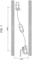
- a lateral acceleration in lane change will be described with reference to FIGS. 1 to 3 so that the invention is easily understood.
- a front-rear direction of the vehicle is set to x
- a direction perpendicular to the longitudinal direction is set to y
- the acceleration in the x direction is a longitudinal acceleration
- the acceleration in the y direction is a lateral acceleration.
- the forward acceleration is positive, that is, the longitudinal acceleration which increases the speed when the vehicle is proceeding in the forward direction is positive.
- the lateral acceleration which is generated when the vehicle is proceeding in the forward direction and turns left (counterclockwise) is positive, and is negative in the opposite direction.
- a left-turning radius is set to be positive, and the reciprocal number thereof is set to a vehicle running curvature.
- a target trajectory also has a left-turning radius as positive, and the reciprocal number thereof is set to a target trajectory curvature.
- a steering angle in the left turning (counterclockwise) direction is set as positive.
- FIG. 2 is a conceptual diagram of lateral acceleration generated in the vehicle when lanes are changed.
- the lane change is divided into the following four sections (P1 to P4), and the end times of the respective sections are T 1 , T 2 , T 3 , and T 4 .
- a lateral acceleration peak value (maximum value) generated at the time of turning is G ytgt
- a lateral acceleration peak value (maximum value) generated at the time of returning is -kG ytgt obtained by multiplying G ytgt by the coefficient k and inverting the sign.
- the lateral acceleration G y in P1 to P4 can be given by, for example, the following Equations (1) to (4).
- G y G ytgt 2 1 ⁇ cos ⁇ 1 t 0 ⁇ t ⁇ T 1 1
- G y G ytgt T 1 ⁇ t ⁇ T 2 2
- G y G ytgt 2 1 ⁇ k + 1 + k cos ⁇ 3 t ⁇ T 2 T 2 ⁇ t ⁇ T 3 3
- G y ⁇ kG ytgt 2 1 + cos ⁇ 4 t ⁇ T 3 T 3 ⁇ t ⁇ T 4 4 4
- V y G ytgt 2 t ⁇ 1 ⁇ 1 sin ⁇ 1 t 0 ⁇ t ⁇ T 1 5
- V y G ytgt ⁇ t + V y 1 T 1 ⁇ t ⁇ T 2 6
- V y G ytgt 2 1 ⁇ k t ⁇ T 2 + 1 ⁇ 3 1 + k sin ⁇ 3 t ⁇ T 2 + V y 2 T 2 ⁇ t ⁇ T 3 7
- V y ⁇ kG ytgt 2 t ⁇ T 3 + 1 ⁇ 4 sin ⁇ 4 t ⁇ T 3 + V y 3 T 3 ⁇ t ⁇ T 4 8
- Y G ytgt 2 t 2 2 + 1 ⁇ 1 2 cos ⁇ 1 t 0 ⁇ t ⁇ T 1 9
- Y 1 2 G ytgt ⁇ t 2 + V y 1 ⁇ t + Y 1 T 1 ⁇ t ⁇
- V y1 , V y2 , V y3 , V y4 , Y 1 , Y 2 , Y 3 , and Y 4 are given by the following Equations (13) to (20), respectively.
- V y 1 G ytgt 2 ⁇ T 1 13
- V y 2 G ytgt ⁇ T 2 + G ytgt 2 ⁇ T 1 14
- V y 3 G ytgt 2 1 ⁇ k T 3 ⁇ T 2 + G ytgt ⁇ T 2 + G ytgt 2 ⁇ T 1 15
- V y 4 ⁇ kG ytgt 2 T 4 ⁇ T 3 + G ytgt 2 1 ⁇ k T 3 ⁇ T 2 + G ytgt ⁇ T 2 + G ytgt 2 ⁇ T 1 16
- Y 1 G ytgt 2 T 1 2 2 ⁇ 1 ⁇ 1 2 17
- Y 2 1 2 G ytg
- T 1 ⁇ ⁇ 1 21
- T 2 ⁇ ⁇ 1 + ⁇ T 2 22
- T 3 ⁇ ⁇ 1 + ⁇ T 2 + ⁇ ⁇ 3 23
- T 4 ⁇ ⁇ 1 + ⁇ T 2 + ⁇ ⁇ 3 + ⁇ ⁇ 4 24
- V y4 and Y 4 are given by the following Equations (25) and (26), respectively.
- V y 4 0 25
- Y 4 Y tgt 26
- Equations (27) and (28) are obtained from the relations of the above Equations (18) to (26) .
- Equations (27) and (28) are as the following five. If three of these unknowns are set, the remaining two will be uniquely determined.
- ⁇ 1 , ⁇ T 2 , and ⁇ 3 are set as constants, and each constant is set so that k becomes 1 or more, and ⁇ 4 and k are calculated. Thereby, a target lateral acceleration G y in the lane change can be created. Further, ⁇ T 2 may be determined based on the lateral movement amount of the vehicle.
- NY pvT2 means which percentage the forward fixation point is located between the initial lane and the target lane.
- ⁇ T 2 As a method of setting ⁇ T 2 , for example, considering the time until Y pvT2 reaches a predetermined ratio (hereinafter ⁇ Ytgt ) of the target lateral movement amount Y tgt , instead of setting ⁇ T 2 itself in advance, the predetermined ratio ⁇ Ytgt of the target lateral movement amount Y tgt is set as the time until Y pvT2 reaches the ratio. Therefore, even when the lane width (lane change width) changes, the lateral acceleration at the time of lane change can be set with a small constant setting.
- ⁇ Ytgt a predetermined ratio
- the description shows an example of a method of creating lateral acceleration control in the invention, and the lateral acceleration control of the invention is not limited only to this method.
- acceleration lateral acceleration, or longitudinal acceleration and lateral acceleration
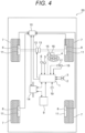
- FIG. 4 illustrates a configuration diagram of a vehicle equipped with the vehicle motion control device according to the first embodiment of the invention.
- the vehicle motion control device 1 of this embodiment is mounted on a vehicle 20, and performs calculation required for the acceleration control based on various types of information obtained from sensors (an acceleration sensor 2, a gyro sensor 3, a wheel speed sensor 8) for acquiring vehicle motion state information, and sensors (a steering angle sensor 5, a brake pedal sensor 17, an accelerator pedal sensor 18) for acquiring driver operation information, and sensors (a course shape acquisition sensor 6, an own vehicle position detection sensor 9, an external information detection sensor 19) for acquiring own vehicle traveling road information.
- a control command value is transmitted to control units (a brake control unit 10, a drive torque control unit 12, a steering angle control unit 15) which control driving of actuators (a brake actuator 11, a drive actuator 13, and a steering angle control actuator 16) capable of control the longitudinal acceleration generated in the vehicle and/or the lateral acceleration, via a communication line 14.
- control units a brake control unit 10, a drive torque control unit 12, a steering angle control unit 15
- actuators a brake actuator 11, a drive actuator 13, and a steering angle control actuator 16
- the sensor for acquiring the vehicle motion state information may be any sensor or devices capable of acquiring a vehicle speed, a longitudinal acceleration, a lateral acceleration, and a yaw rate, and is not limited to the above sensor configuration.
- the vehicle speed may be acquired by differentiating the position information obtained by the global positioning system (GPS).
- GPS global positioning system
- the yaw rate, the longitudinal acceleration, and the lateral acceleration of the vehicle may be acquired using an image acquisition sensor such as a camera.
- the vehicle motion control device 1 may not need to have a direct sensor input.
- the necessary information may be acquired through the communication line 14 from a separate unit (for example, the brake control unit 10).
- the vehicle motion control device 1 may not have to wait the direct input from the sensor similarly to the acquisition of the vehicle motion state information described above.
- the necessary information may be acquired through the communication line 14 from a separate unit (for example, the brake control unit 10).
- a global positioning system is used as a sensor to acquire the own vehicle traveling road information as the own vehicle position detection sensor 9, and the external information detection sensor 19 is used as a sensor to detect obstacles around the own vehicle, such as cameras and radars so as to detect a travelable region, and a course shape acquisition sensor 6 is used as a sensor to acquire the traveling route information of the own vehicle, such as a navigation system.
- the sensor for acquiring the own vehicle traveling road information may be any device as long as it can acquire the course shape and the travelable region in the traveling direction of the own vehicle, and is not limited to these sensors.
- a method of acquiring the course shape in front of the own vehicle by communication with a data center or a device that transmits road information installed on the road may be employed, or a method of acquiring an image in front of or around the own vehicle by an imaging device such as a camera, or both images to acquire the course shape in front of the own vehicle.
- an imaging device such as a camera
- there may be employed a method of acquiring the course shape from a unit, which calculates the course shape in the traveling direction of the own vehicle, through the communication line 14 by any of these devices or a combination thereof may be employed.
- An acceleration/deceleration actuator capable of controlling the longitudinal acceleration generated in the vehicle 20 is an actuator which can control the longitudinal acceleration generated in the vehicle 20 by controlling a force generated between a tire 7 and the road surface.
- an acceleration/deceleration actuator which can control the longitudinal acceleration such as a combustion engine which can control braking/driving torque applied on the tire 7 by controlling a combustion state and can control the longitudinal acceleration of the vehicle 20, an electric motor which can control the braking/driving torque applied on the tire 7 by controlling a current and control the longitudinal acceleration of the vehicle 20, a transmission which can control the longitudinal acceleration of the vehicle 20 by changing a gear ratio when power is transmitted to each front wheel, or a friction brake which generates the longitudinal acceleration to the vehicle 20 by pressing a brake disk to a brake pad of each front wheel.
- the vehicle motion control device 1 is provided with an arithmetic device which has a memory region, an arithmetic processing capability, and signal input/output units.
- the vehicle motion control device calculates a longitudinal acceleration command value to be generated in the vehicle 20 from various types of information obtained from the vehicle motion state information, the driver operation information, and the own vehicle traveling road information, and transmits the longitudinal acceleration command value to a drive controller (the brake control unit 10, and the drive torque control unit 12) of the acceleration/deceleration actuator (the brake actuator 11, and the drive actuator 13) using the acceleration/deceleration actuator capable of generating the longitudinal acceleration serving as the longitudinal acceleration command value as a longitudinal acceleration generation unit.
- a lateral motion command to be generated in the vehicle 20 is calculated from various types of information obtained from the vehicle motion state information, the driver operation information, and the own vehicle traveling road information.
- a steering command value as the lateral motion command value is sent to the drive controller (the steering angle control unit 15) of the steering angle control actuator 16 using the steering angle control actuator 16 as a turning motion generating unit which can generate the lateral motion (details will be described later).
- the signal sent from the vehicle motion control device 1 is not the longitudinal acceleration itself, but may be any signal that can realize the longitudinal acceleration command value by the acceleration/deceleration actuator.
- the signal sent from the vehicle motion control device 1 is not the steering angle itself, but may be any signal that can realize the steering angle command value by the steering angle control actuator 16.
- a braking/driving torque command value which can realize the longitudinal acceleration command value may be sent to the drive torque control unit 12.
- a driving signal of the combustion engine realizing the longitudinal acceleration command value may be directly transmitted to the control actuator of the combustion engine without through the drive torque control unit 12.
- a hydraulic command value realizing the longitudinal acceleration command value is sent to the brake control unit 10.
- the driving signal of the driving actuator of the hydraulic friction brake realizing the longitudinal acceleration command value may be directly sent to the driving actuator of the hydraulic friction brake without through the brake control unit 10.
- the acceleration/deceleration actuator which performs the driving control may be changed according to the longitudinal acceleration command value.
- the combustion engine is controlled in driving if the longitudinal acceleration command value falls within a range which can be realized by controlling the braking/driving torque of the combustion engine, and the hydraulic friction brake is controlled in driving together with the combustion engine in a case where the longitudinal acceleration command value is a negative value within a range which cannot be realized by controlling the braking/driving torque of the combustion engine.
- the electric motor and the combustion engine are provided as the acceleration/deceleration actuator, the electric motor is drive-controlled when the temporal change in the longitudinal acceleration is large, and the combustion engine is drive-controlled when the temporal change in the longitudinal acceleration is small.
- the longitudinal acceleration command value may be controlled in driving by the electric motor.
- another acceleration/deceleration actuator (the combustion engine, the hydraulic friction brake, etc.) may be controlled in driving.
- the communication line 14 a communication line and a communication protocol which differ depending on a signal may be used.
- the ethernet may be used for the communication with a sensor acquiring the own vehicle traveling road information which necessarily transfers a large amount of data.
- Controller Area Network CAN may be used when the communication is performed with the actuator.
- FIG. 5 illustrates a configuration diagram of the vehicle motion control device 1 according to the first embodiment of the invention.
- the vehicle motion control device 1 includes a target trajectory acquisition unit 1a, a vehicle motion state acquisition unit 1b, a vehicle motion control calculation unit 1c, and a control command transmission unit 1d.
- the target trajectory acquisition unit 1a acquires a target trajectory and a travelable region to be generated in the vehicle 20 to travel based on the own vehicle traveling road information and the vehicle motion state information.
- the method of creating the target trajectory may be a method of creating a target trajectory from the course shape in which the own vehicle travels and obstacle information, or a method of creating the target trajectory based on the travelable region acquired by the own vehicle through communication with the data center.
- the vehicle motion state acquisition unit 1b acquires a motion state amount (traveling speed, turning state, and driver operation amount) of the vehicle 20 from the vehicle motion state information.
- the vehicle motion control calculation unit 1c calculates the longitudinal acceleration command value by the speed control, or both the longitudinal acceleration command value by the speed control and the steering angle command value by the steering angle control based on the information obtained by the target trajectory acquisition unit 1a and the vehicle motion state acquisition unit 1b, and sends the calculation result to the control command transmission unit 1d.
- the control command transmission unit 1d sends a control command value to each control unit (the brake control unit 10, the drive torque control unit 12, and the steering angle control unit 15) which performs the driving control of the actuator (the brake actuator 11, the drive actuator 13, and the steering angle control actuator 16) which can control the longitudinal acceleration and/or actual steering angle of the tire, based on the longitudinal acceleration command value created by the vehicle motion control calculation unit 1c or both the longitudinal acceleration command value and the steering command value.
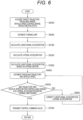
- FIG. 6 illustrates a control flowchart in the vehicle motion control device 1 of the first embodiment.
- a target trajectory, a travelable range, a vehicle speed control range, and a vehicle motion state are acquired as described above.
- the target trajectory may be acquired by a method of providing a lane changeable region (deltaX, deltaY), a vehicle speed control range, and a target lateral movement distance Y tgt , or a method of providing a target lateral position at a predetermined proceeding distance position.
- a turning limit of the vehicle 20 is estimated from the vehicle motion state during a primary steering period. For example, if a turning responsiveness of the vehicle (on the traveling road surface) to the steering input at the start of the lane change is worse than the responsiveness under preset conditions (for example, the response to the same input on a dry road surface), the turning limit is set low according to the degree of decrease in responsiveness.
- the longitudinal acceleration is calculated from the target trajectory, the vehicle speed control range, and the vehicle motion state. For example, when the vehicle speed is higher than the vehicle speed control range, a negative longitudinal acceleration command value is calculated so as to be within the vehicle speed control range.
- the lateral acceleration is calculated from the target trajectory, the vehicle motion state, and the turning limit.
- the calculation of the lateral acceleration is performed, for example, by the method illustrated in FIGS. 1 to 3 .
- the lateral acceleration is calculated (controlled) such that the maximum lateral acceleration (absolute value) generated on the secondary steering side (lateral acceleration generation phase in the lateral direction opposite to the moving direction at the time of lane change) is equal or more than the maximum lateral acceleration (absolute value) generated on the primary steering side (lateral acceleration generation phase in the same direction as a lateral moving direction at the time of lane change).
- the time during which the generated lateral acceleration is constant during the primary steering period (P2 in FIG. 2 : holding section after turning) becomes shorter as the generated lateral acceleration increases.
- the relation between the time at which the generated lateral acceleration is constant and the generated lateral acceleration changes according to the lane width (lane change width).
- the initial value of the setting constant may be a value that is set in advance, or may be a value that is changed according to the occupant's preference.
- the longitudinal acceleration based on the lateral motion is calculated.
- a method of calculating the longitudinal acceleration based on the lateral motion for example, longitudinal acceleration control based on a lateral acceleration increasing rate disclosed in PTL 3 is exemplified.
- the traveling trajectory and vehicle speed of the vehicle 20 are estimated based on the vehicle motion state, the calculated lateral acceleration, and the longitudinal acceleration.
- the vehicle speed is estimated such that the vehicle speed is constant or decreases.
- S500 it is determined whether the estimated traveling trajectory and vehicle speed are within a controllable range, and whether the lateral acceleration is within a turning limit range.
- the process proceeds to S600, and if it is determined to be within the control range, the process proceeds to S700.
- the longitudinal acceleration and the lateral acceleration are corrected.
- the traveling trajectory is changed in S400 by changing various setting variables illustrated in Equations (1) to (28).
- the traveling trajectory and the vehicle speed are changed in S400 by changing a control gain of the longitudinal acceleration control based on the lateral acceleration increasing rate disclosed in PTL 3.
- the setting constants are set so that the maximum lateral acceleration (absolute value) on the secondary steering side is equal to or greater than the maximum lateral acceleration (absolute value) on the primary steering side and within the turning limit range.
- the maximum lateral acceleration (absolute value) on the secondary steering side be set to a value to twice or less than the maximum lateral acceleration (absolute value) on the primary steering side so that the lateral acceleration difference between the steering side and the secondary steering side does not become excessive and the ride comfort of the occupant does not deteriorate.
- a control command value for each actuator is calculated and transmitted based on the longitudinal acceleration command value and the lateral acceleration command value. For example, when controlling the longitudinal acceleration using a combustion engine and controlling a yaw moment (lateral acceleration) using an electric power steering, a braking/driving torque command value for causing the vehicle to generate the longitudinal acceleration is sent to the controller of the combustion engine. The steering angle command value for causing the vehicle to generate the lateral acceleration is sent to the controller of the electric power steering.
- the method of creating the steering angle command value based on the lateral acceleration command value has been described, but a method of directly creating the steering angle command value from the vehicle speed and the lateral movement amount at the time of lane change may be used.
- a method of controlling the steering angle of the vehicle 20 such that the maximum steering angle absolute value on the secondary steering side is equal to or greater than the maximum steering angle absolute value on the primary steering side using a map of the relation between the vehicle speed and the lateral movement amount created in advance.
- the turning limit is estimated based on the turning responsiveness of the vehicle 20 during the primary steering (the lane change start side) while the lateral acceleration generated on the primary steering side is suppressed.
- the lateral acceleration on the secondary steering side within the turning limit range, it is possible to change lanes without excessively suppressing the lateral acceleration while disturbance of the vehicle behavior on the primary steering side is suppressed.
- the occupant is in a state under the occurrence of lateral acceleration, and even if the lateral acceleration on the secondary steering side has a slightly larger value than the primary steering side that transits from straight running state to lateral motion, it is considered that the comfort of the occupant is not significantly impaired.
- FIG. 7 the configuration and operation of a vehicle motion control device (target trajectory generation device) according to a second embodiment of the invention will be described using FIG. 7 .
- FIG. 7 illustrates a configuration diagram of a vehicle motion control device (target trajectory generation device) 1A according to the second embodiment of the invention.
- the vehicle motion control device (target trajectory generation device) 1A is provided outside the vehicle 20, but may be provided in the vehicle 20 as in the first embodiment.
- the vehicle motion control device 1A includes a plurality of arithmetic devices having a memory region, an arithmetic processing capability, a signal input/output unit, and the like, and mainly includes a trajectory calculation unit 1Aa and a travel control calculation unit 1Ab.
- the trajectory calculation unit 1Aa creates a target trajectory and a target vehicle speed of the vehicle 20 from the course shape, the external information, the own vehicle position information, and the vehicle motion state information.
- the travel control calculation unit 1Ab calculates a lateral motion command value to be generated in the vehicle 20 or both a lateral motion command value and a longitudinal acceleration command value from the target trajectory, the target vehicle speed, and the vehicle motion state information.
- the longitudinal acceleration command value is sent to a drive controller (the brake control unit 10, and the drive torque control unit 12) for the acceleration/deceleration actuator (the brake actuator 11, and the drive actuator 13), using the acceleration/deceleration actuator capable of generating a longitudinal acceleration serving as the longitudinal acceleration command value as a longitudinal acceleration generation unit.
- the steering angle control actuator 16 which can generate the lateral motion command value to be generated in the vehicle 20 is used as a turning motion generating unit, and sends the steering command value as the lateral motion command value to the drive controller (the steering angle control unit 15) of the steering angle control actuator 16.
- the trajectory calculation unit 1Aa when generating a target trajectory and a target vehicle speed from the course shape, the external information, the own vehicle position information, and the vehicle motion state information, the trajectory calculation unit 1Aa generates the target trajectory and the target vehicle speed such that the absolute value of the maximum lateral acceleration generated in the vehicle 20 on the secondary steering side becomes equal to or greater than the absolute value of the maximum lateral acceleration generated in the vehicle 20 on the primary steering side (see FIG. 2 ).
- the target trajectory at the time of lane change is created such that the maximum curvature value of the target trajectory (traveling trajectory) on the secondary steering side is equal to or greater than the maximum curvature value of the target trajectory (traveling trajectory) on the primary steering side (in other words, the maximum curvature value of the traveling trajectory on the secondary steering side becomes equal to or greater than the maximum curvature value of the traveling trajectory on the primary steering side).
- the travel control calculation unit 1Ab calculates a lateral motion command value to be generated in the vehicle 20 or both a lateral motion command value and a longitudinal acceleration command value to realize the target trajectory and the target vehicle speed created by the trajectory calculation unit 1Aa.
- the longitudinal acceleration command value is sent to a drive controller (the brake control unit 10, and the drive torque control unit 12) for the acceleration/deceleration actuator (the brake actuator 11, and the drive actuator 13), using the acceleration/deceleration actuator capable of generating a longitudinal acceleration serving as the longitudinal acceleration command value as a longitudinal acceleration generation unit.
- the steering angle control actuator 16 which can generate the lateral motion command value to be generated in the vehicle 20 is used as a turning motion generating unit, and sends the steering command value as the lateral motion command value to the drive controller (the steering angle control unit 15) of the steering angle control actuator 16.
- the vehicle motion control device (target trajectory generation device) 1A when the vehicle motion control device (target trajectory generation device) 1A generates the target trajectory, the target trajectory and the target vehicle speed are created such that the absolute value of the maximum lateral acceleration generated in the vehicle 20 on the secondary steering side becomes equal to or greater than the absolute value of the maximum lateral acceleration generated in the vehicle 20 on the primary steering side. Therefore, the vehicle can travel within the travelable range, and the lateral acceleration generated in the vehicle 20 can be controlled such that the absolute value of the maximum lateral acceleration generated in the vehicle 20 on the secondary steering side becomes equal to or greater than the absolute value of the maximum lateral acceleration generated in the vehicle 20 on the primary steering side.
- the calculation load on the travel control calculation unit 1Ab can be reduced, and it is possible to realize control in which the trajectory calculation device (the trajectory calculation unit 1Aa) is combined with another travel control calculation device (the travel control calculation unit 1Ab).
- Each of the above configurations, functions, processing units, processing means, and the like may be partially or entirely achieved by hardware by, for example, designing an integrated circuit.
- Each of the above configurations, functions, and the like may be achieved by software by a processor interpreting and executing a program that achieves each function.
- Information such as a program, a table, and a file for achieving each function can be stored in a memory device such as a memory, a hard disk, or a solid-state drive (SSD), or a recording medium such as an integrated circuit (IC) card, a secure digital (SD) card, or a digital versatile disc (DVD).
- a memory device such as a memory, a hard disk, or a solid-state drive (SSD), or a recording medium such as an integrated circuit (IC) card, a secure digital (SD) card, or a digital versatile disc (DVD).
- IC integrated circuit
- SD secure digital
- DVD digital versatile disc
- control lines and information lines considered to be necessary for explanation are illustrated, but not all the control lines and the information lines for a product are illustrated. In practice, almost all the configurations may be considered to be connected to each other.
Landscapes
- Engineering & Computer Science (AREA)
- Transportation (AREA)
- Mechanical Engineering (AREA)
- Chemical & Material Sciences (AREA)
- Combustion & Propulsion (AREA)
- Automation & Control Theory (AREA)
- Physics & Mathematics (AREA)
- Mathematical Physics (AREA)
- Steering Control In Accordance With Driving Conditions (AREA)
- Control Of Driving Devices And Active Controlling Of Vehicle (AREA)
Claims (8)
- Fahrzeugbewegungssteuervorrichtung (1) eines Fahrzeugs (20), die eine am Fahrzeug (20) erzeugte Querbeschleunigung zum Zeitpunkt eines Spurenwechsels automatisch steuern kann, dadurch gekennzeichnet, dass, wenn eine Phase, in der die Querbeschleunigung in die gleiche Richtung wie eine Querbewegungsrichtung zum Zeitpunkt eines Spurenwechsel erzeugt wird, als eine primäre Lenkseite eines Spurenwechsels definiert ist, und eine Phase, in der die Querbeschleunigung in eine Richtung entgegengesetzt zur Querbewegungsrichtung zum Zeitpunkt eines Spurenwechsels erzeugt wird, als eine sekundäre Lenkseite eines Spurenwechsels definiert ist,
eine Querbewegung des Fahrzeugs (20) so gesteuert wird, dass der Absolutwert einer maximalen Querbeschleunigung, die während einer primären Lenkung des Spurenwechsels erzeugt wird, für eine vorbestimmte Zeit konstant ist und der Absolutwert einer maximalen Querbeschleunigung, die zum Zeitpunkt einer sekundären Lenkung eines Spurenwechsels erzeugt wird, gleich wie oder größer als der Absolutwert einer maximalen Querbeschleunigung wird, die zum Zeitpunkt einer primären Lenkung eines Spurenwechsels erzeugt wird. - Fahrzeugbewegungssteuervorrichtung (1) nach Anspruch 1,
wobei die Variation einer Querbeschleunigung während der primären Lenkung eines Spurenwechsels so gesteuert wird, dass bei einer Erhöhung des maximalen Absolutwerts der erzeugten Querbeschleunigung bezogen auf die Zeit, die Zeit, in der die erzeugte Querbeschleunigung konstant ist, verkürzt ist. - Fahrzeugbewegungssteuervorrichtung (1) nach Anspruch 1, wobei der Absolutwert der maximalen Querbeschleunigung, die während der sekundären Lenkung eines Spurenwechsels erzeugt wird, gleich groß wie oder weniger als doppelt so groß wie der Absolutwert der maximalen Querbeschleunigung ist, die während der primären Lenkung eines Spurenwechsels erzeugt wird.
- Fahrzeugbewegungssteuervorrichtung (1) nach Anspruch 1,wobei in einem Abschnitt, in dem der Absolutwert der Querbeschleunigung, die während der sekundären Lenkung eines Spurenwechsels erzeugt wird, nachdem eine Lenkung zum Zeitpunkt eines Spurenwechsels begonnen hat, maximiert ist,die Querbewegung des Fahrzeugs (20) so gesteuert wird, dass die Geschwindigkeit des Fahrzeugs (20) konstant ist oder abnimmt.
- Fahrzeugbewegungssteuervorrichtung (1) nach Anspruch 1,
wobei während der primären Lenkung eines Spurenwechsels eine Drehgrenze des Fahrzeugs (1) auf einer befahrenen Straßenoberfläche geschätzt wird. - Fahrzeugbewegungssteuerverfahren eines Fahrzeugs (20), das eine am Fahrzeug (20) erzeugte Querbeschleunigung zum Zeitpunkt eines Spurenwechsels automatisch steuern kann, dadurch gekennzeichnet, dass, wenn eine Phase, in der die Querbeschleunigung in die gleiche Richtung wie eine Querbewegungsrichtung zum Zeitpunkt eines Spurenwechsel erzeugt wird, als eine primäre Lenkseite eines Spurenwechsels definiert ist, und eine Phase, in der die Querbeschleunigung in eine Richtung entgegengesetzt zur Querbewegungsrichtung zum Zeitpunkt eines Spurenwechsels erzeugt wird, als eine sekundäre Lenkseite eines Spurenwechsels definiert ist,
eine Querbewegung des Fahrzeugs (20) so gesteuert wird, dass der Absolutwert einer maximalen Querbeschleunigung, die während einer primären Lenkung des Spurenwechsels erzeugt wird, für eine vorbestimmte Zeit konstant ist und der Absolutwert einer maximalen Querbeschleunigung, die zum Zeitpunkt einer sekundären Lenkung eines Spurenwechsels erzeugt wird, gleich wie oder größer als der Absolutwert einer maximalen Querbeschleunigung wird, die zum Zeitpunkt einer primären Lenkung eines Spurenwechsels erzeugt wird. - Fahrzeugbewegungssteuerprogramm eines Fahrzeugs (20), das eine am Fahrzeug (20) erzeugte Querbeschleunigung zum Zeitpunkt eines Spurenwechsels automatisch steuern kann, dadurch gekennzeichnet, dass, wenn eine Phase, in der die Querbeschleunigung in die gleiche Richtung wie eine Querbewegungsrichtung zum Zeitpunkt eines Spurenwechsel erzeugt wird, als eine primäre Lenkseite eines Spurenwechsels definiert ist, und eine Phase, in der die Querbeschleunigung in eine Richtung entgegengesetzt zur Querbewegungsrichtung zum Zeitpunkt eines Spurenwechsels erzeugt wird, als eine sekundäre Lenkseite eines Spurenwechsels definiert ist,
eine Querbewegung des Fahrzeugs (20) so gesteuert wird, dass der Absolutwert einer maximalen Querbeschleunigung, die während einer primären Lenkung des Spurenwechsels erzeugt wird, für eine vorbestimmte Zeit konstant ist und der Absolutwert einer maximalen Querbeschleunigung, die zum Zeitpunkt einer sekundären Lenkung einer Spurenwechsels erzeugt wird, gleich wie oder größer als der Absolutwert einer maximalen Querbeschleunigung wird, die zum Zeitpunkt einer primären Lenkung eines Spurenwechsels erzeugt wird. - Fahrzeugbewegungssteuervorrichtung nach einem der Ansprüche 1 bis 5, die weiters Folgendes umfasst:eine Fahrzeugbewegungssteuerberechnungseinheit (1c), die eine Querbeschleunigung, die an einem Fahrzeug (20) zum Zeitpunkt eines Spurenwechsels erzeugt wird, automatisch steuert;eine Zielroutenerfassungseinheit (1a), die eine Zielroute für die Fahrt des Fahrzeugs (20) erfasst; undeine Fahrzeugbewegungszustandserfassungseinheit (1b), die den Bewegungszustand des Fahrzeugs (20) erfasst.
Applications Claiming Priority (2)
| Application Number | Priority Date | Filing Date | Title |
|---|---|---|---|
| JP2017216646A JP6976142B2 (ja) | 2017-11-09 | 2017-11-09 | 車両運動制御装置、その方法、そのプログラム、及びそのシステム、並びに、目標軌道生成装置、その方法、そのプログラム、及びそのシステム |
| PCT/JP2018/037602 WO2019093046A1 (ja) | 2017-11-09 | 2018-10-09 | 車両運動制御装置、その方法、そのプログラム、及びそのシステム、並びに、目標軌道生成装置、その方法、そのプログラム、及びそのシステム |
Publications (3)
| Publication Number | Publication Date |
|---|---|
| EP3708464A1 EP3708464A1 (de) | 2020-09-16 |
| EP3708464A4 EP3708464A4 (de) | 2021-11-03 |
| EP3708464B1 true EP3708464B1 (de) | 2024-03-27 |
Family
ID=66437707
Family Applications (1)
| Application Number | Title | Priority Date | Filing Date |
|---|---|---|---|
| EP18877166.1A Active EP3708464B1 (de) | 2017-11-09 | 2018-10-09 | Vorrichtung, verfahren, programm und system zur fahrzeugbewegungssteuerung sowie vorrichtung, verfahren, programm und system zur erstellung einer zielbahn |
Country Status (4)
| Country | Link |
|---|---|
| US (1) | US11731631B2 (de) |
| EP (1) | EP3708464B1 (de) |
| JP (1) | JP6976142B2 (de) |
| WO (1) | WO2019093046A1 (de) |
Families Citing this family (13)
| Publication number | Priority date | Publication date | Assignee | Title |
|---|---|---|---|---|
| JP6976142B2 (ja) * | 2017-11-09 | 2021-12-08 | 日立Astemo株式会社 | 車両運動制御装置、その方法、そのプログラム、及びそのシステム、並びに、目標軌道生成装置、その方法、そのプログラム、及びそのシステム |
| CN112638749B (zh) * | 2018-09-07 | 2023-03-24 | 日产自动车株式会社 | 车辆的行驶控制方法及行驶控制装置 |
| JP7207099B2 (ja) * | 2019-03-29 | 2023-01-18 | マツダ株式会社 | 自動車走行制御用の演算装置及びそれを用いた走行制御システム |
| JP7259574B2 (ja) * | 2019-06-17 | 2023-04-18 | 株式会社ジェイテクト | 制御装置、および転舵装置 |
| US11548520B2 (en) * | 2019-10-11 | 2023-01-10 | Mitsubishi Electric Research Laboratories, Inc. | Control of autonomous vehicles adaptive to user driving preferences |
| DE102019129879A1 (de) * | 2019-11-06 | 2021-05-06 | Zf Friedrichshafen Ag | Verfahren sowie Steuergerät zum Steuern eines Kraftfahrzeugs |
| WO2022064236A1 (ja) * | 2020-09-28 | 2022-03-31 | 日産自動車株式会社 | 車両運動制御方法及び車両運動制御装置 |
| US12024170B2 (en) * | 2020-12-14 | 2024-07-02 | Zoox, Inc. | Lane change gap finder |
| CN112937608B (zh) * | 2021-03-31 | 2022-06-21 | 吉林大学 | 一种基于轨迹预测的冰雪环境无人驾驶车辆一体化滚动决策方法、装置及存储介质 |
| US11891061B2 (en) * | 2021-06-17 | 2024-02-06 | Ford Global Technologies, Llc | Target vehicle detection |
| JP2023027676A (ja) * | 2021-08-17 | 2023-03-02 | トヨタ自動車株式会社 | 車線逸脱防止装置 |
| CN115959154A (zh) * | 2022-12-14 | 2023-04-14 | 阿波罗智联(北京)科技有限公司 | 变道轨迹的生成方法、装置和存储介质 |
| JP2025133462A (ja) * | 2024-03-01 | 2025-09-11 | トヨタ自動車株式会社 | 運転支援装置 |
Family Cites Families (50)
| Publication number | Priority date | Publication date | Assignee | Title |
|---|---|---|---|---|
| US4679809A (en) * | 1984-09-10 | 1987-07-14 | Nissan Motor Co., Ltd. | Steering control system for wheeled vehicle |
| JPH01141174A (ja) * | 1987-11-26 | 1989-06-02 | Daihatsu Motor Co Ltd | ステアリング装置 |
| DE10356510A1 (de) * | 2003-12-03 | 2005-07-07 | Robert Bosch Gmbh | Fahrdynamikregelung mit vorgezogenem Druckaufbau am zu regelnden Rad |
| JP3979400B2 (ja) * | 2004-04-23 | 2007-09-19 | 日産自動車株式会社 | 前方道路対応制御装置 |
| JP4568302B2 (ja) | 2007-05-18 | 2010-10-27 | 株式会社日立製作所 | 加加速度情報を用いた車両の前後加速度制御装置 |
| US8428843B2 (en) * | 2008-06-20 | 2013-04-23 | GM Global Technology Operations LLC | Method to adaptively control vehicle operation using an autonomic vehicle control system |
| JP5572485B2 (ja) * | 2010-08-31 | 2014-08-13 | 日立オートモティブシステムズ株式会社 | サスペンション制御装置 |
| US20120283912A1 (en) * | 2011-05-05 | 2012-11-08 | GM Global Technology Operations LLC | System and method of steering override end detection for automated lane centering |
| JP2012236512A (ja) * | 2011-05-12 | 2012-12-06 | Nissan Motor Co Ltd | 車両用立位姿勢保持装置 |
| WO2013066216A1 (en) * | 2011-10-31 | 2013-05-10 | Volvo Lastvagnar Ab | Method and arrangement for vehicle stabilization |
| AU2011380326A1 (en) * | 2011-10-31 | 2014-04-24 | Volvo Lastvagnar Ab | Method and arrangement for vehichle stabilization |
| JP2013148948A (ja) * | 2012-01-17 | 2013-08-01 | Toyota Motor Corp | 車線検出装置 |
| JP5970322B2 (ja) * | 2012-10-01 | 2016-08-17 | 日立オートモティブシステムズ株式会社 | 車両の運動制御装置 |
| JP6201561B2 (ja) | 2013-09-20 | 2017-09-27 | 株式会社デンソー | 走行軌道生成装置、および走行軌道生成プログラム |
| EP2853457B1 (de) * | 2013-09-30 | 2019-11-27 | Hitachi, Ltd. | Verfahren und Vorrichtung zur Fahrhilfedurchführung |
| JP6416574B2 (ja) * | 2014-09-29 | 2018-10-31 | 日立オートモティブシステムズ株式会社 | 車両の制御方法、車両制御システム、車両制御装置、および制御プログラム |
| WO2016110732A1 (ja) * | 2015-01-05 | 2016-07-14 | 日産自動車株式会社 | 目標経路生成装置および走行制御装置 |
| JP6137212B2 (ja) * | 2015-02-02 | 2017-05-31 | トヨタ自動車株式会社 | 運転支援装置 |
| DE102015201878A1 (de) * | 2015-02-04 | 2016-08-04 | Continental Teves Ag & Co. Ohg | Halbautomatisierter Spurwechsel |
| JP6593695B2 (ja) * | 2015-09-15 | 2019-10-23 | 日野自動車株式会社 | 車線変更操舵制御システム |
| JP6728620B2 (ja) * | 2015-10-13 | 2020-07-22 | 日産自動車株式会社 | 操舵支援装置及び操舵支援方法 |
| JP6409744B2 (ja) | 2015-11-06 | 2018-10-24 | 株式会社アドヴィックス | 車両の走行支援装置 |
| JP6316265B2 (ja) * | 2015-12-01 | 2018-04-25 | 本田技研工業株式会社 | 車線変更制御装置 |
| JP6308233B2 (ja) * | 2016-02-29 | 2018-04-11 | トヨタ自動車株式会社 | 車両制御装置及び車両制御方法 |
| JP2017165156A (ja) | 2016-03-14 | 2017-09-21 | 本田技研工業株式会社 | 車両制御システム、車両制御方法、および車両制御プログラム |
| JP6473727B2 (ja) * | 2016-09-09 | 2019-02-20 | 本田技研工業株式会社 | 走行制御装置 |
| JP6654121B2 (ja) * | 2016-09-23 | 2020-02-26 | 日立オートモティブシステムズ株式会社 | 車両運動制御装置 |
| KR102313025B1 (ko) * | 2017-04-03 | 2021-10-15 | 현대자동차주식회사 | 차량 및 그 제어방법 |
| US11008039B2 (en) * | 2017-04-12 | 2021-05-18 | Toyota Jidosha Kabushiki Kaisha | Lane change assist apparatus for vehicle |
| JP6763344B2 (ja) * | 2017-04-12 | 2020-09-30 | トヨタ自動車株式会社 | 車線変更支援装置 |
| US10814913B2 (en) * | 2017-04-12 | 2020-10-27 | Toyota Jidosha Kabushiki Kaisha | Lane change assist apparatus for vehicle |
| JP6801591B2 (ja) * | 2017-06-06 | 2020-12-16 | トヨタ自動車株式会社 | 操舵支援装置 |
| JP6589941B2 (ja) * | 2017-06-06 | 2019-10-16 | トヨタ自動車株式会社 | 操舵支援装置 |
| JP6791021B2 (ja) * | 2017-06-06 | 2020-11-25 | トヨタ自動車株式会社 | 操舵支援装置 |
| JP6596045B2 (ja) * | 2017-08-25 | 2019-10-23 | 株式会社Subaru | 車両の運転支援装置 |
| JP6638178B2 (ja) * | 2017-08-29 | 2020-01-29 | 本田技研工業株式会社 | 車両制御システム、車両制御方法、およびプログラム |
| JP6568559B2 (ja) * | 2017-09-13 | 2019-08-28 | 株式会社Subaru | 車両の走行制御装置 |
| JP6976142B2 (ja) * | 2017-11-09 | 2021-12-08 | 日立Astemo株式会社 | 車両運動制御装置、その方法、そのプログラム、及びそのシステム、並びに、目標軌道生成装置、その方法、そのプログラム、及びそのシステム |
| CN112638749B (zh) * | 2018-09-07 | 2023-03-24 | 日产自动车株式会社 | 车辆的行驶控制方法及行驶控制装置 |
| CN112996692A (zh) * | 2018-11-06 | 2021-06-18 | 日产自动车株式会社 | 乘员姿势控制方法及乘员姿势控制装置 |
| JP7125232B2 (ja) * | 2018-11-30 | 2022-08-24 | トヨタ自動車株式会社 | 操舵判定装置及び自動運転システム |
| JP2020117040A (ja) * | 2019-01-23 | 2020-08-06 | Ntn株式会社 | 車両の姿勢制御装置 |
| FR3093305B1 (fr) * | 2019-02-28 | 2021-01-29 | Psa Automobiles Sa | Régulation de la vitesse d’un véhicule lors d’un dépassement en virage |
| JP7380674B2 (ja) * | 2019-03-20 | 2023-11-15 | ソニーグループ株式会社 | 情報処理装置と情報処理方法および移動制御装置と移動制御方法 |
| JP7216589B2 (ja) * | 2019-03-25 | 2023-02-01 | 株式会社Subaru | 自動操舵制御装置 |
| US12195083B2 (en) * | 2019-06-26 | 2025-01-14 | The Regents Of The University Of Michigan | Lane change maneuvers with minimized tire slip |
| JP7348775B2 (ja) * | 2019-08-28 | 2023-09-21 | 株式会社Subaru | 車両の車線逸脱抑制制御装置 |
| US11130493B2 (en) * | 2019-12-30 | 2021-09-28 | Automotive Research & Testing Center | Trajectory planning method for lane changing, and driver assistance system for implementing the same |
| US20220073098A1 (en) * | 2020-09-09 | 2022-03-10 | GM Global Technology Operations LLC | Method and apparatus for predicting lateral acceleration prior to an automated lane change |
| FR3121411B1 (fr) * | 2021-04-06 | 2023-10-27 | Renault Sas | Procédé de commande de trajectoire de changement de voie pour véhicule autonome. |
-
2017
- 2017-11-09 JP JP2017216646A patent/JP6976142B2/ja active Active
-
2018
- 2018-10-09 EP EP18877166.1A patent/EP3708464B1/de active Active
- 2018-10-09 WO PCT/JP2018/037602 patent/WO2019093046A1/ja not_active Ceased
- 2018-10-09 US US16/757,507 patent/US11731631B2/en active Active
Also Published As
| Publication number | Publication date |
|---|---|
| WO2019093046A1 (ja) | 2019-05-16 |
| EP3708464A4 (de) | 2021-11-03 |
| JP2019085048A (ja) | 2019-06-06 |
| JP6976142B2 (ja) | 2021-12-08 |
| US11731631B2 (en) | 2023-08-22 |
| US20210362720A1 (en) | 2021-11-25 |
| EP3708464A1 (de) | 2020-09-16 |
Similar Documents
| Publication | Publication Date | Title |
|---|---|---|
| EP3708464B1 (de) | Vorrichtung, verfahren, programm und system zur fahrzeugbewegungssteuerung sowie vorrichtung, verfahren, programm und system zur erstellung einer zielbahn | |
| CN110799399B (zh) | 车辆运动控制装置及其方法、和目标轨道生成装置及其方法 | |
| EP3369634B1 (de) | Fahrzeugbewegungsteuerungsvorrichtung und -verfahren | |
| US7860653B2 (en) | Obstacle avoidance control apparatus | |
| US9233692B2 (en) | Method to control a vehicle path during autonomous braking | |
| EP3530535B1 (de) | Fahrzeugbewegungssteuerungsvorrichtung, fahrzeugbewegungssteuerungsverfahren und fahrzeugbewegungssteuerungsprogramm | |
| CN110877610A (zh) | 碰撞回避装置 | |
| JPWO2016189649A1 (ja) | 停車位置設定装置及び方法 | |
| WO2018047873A1 (ja) | 加減速制御システム、加減速制御方法 | |
| JP2009292345A (ja) | 運転支援装置 | |
| EP4397553B1 (de) | Fahrzeugsteuerungsverfahren und fahrzeugsteuerungsvorrichtung | |
| WO2016194168A1 (ja) | 走行制御装置及び方法 | |
| EP4434839B1 (de) | Antriebssteuerungsverfahren und antriebssteuerungsvorrichtung | |
| US20190202493A1 (en) | Vehicle control apparatus | |
| JP7706350B2 (ja) | 移動体制御装置、移動体制御方法、およびプログラム | |
| US20210362781A1 (en) | System and method for active steering control with automatic torque compensation | |
| JP7831096B2 (ja) | 車両制御方法及び車両制御装置 | |
| JP5119691B2 (ja) | 操舵制御装置 | |
| JP7790125B2 (ja) | 軌道生成システム、軌道生成装置、軌道生成方法、軌道生成プログラム | |
| JP7764901B2 (ja) | 車両制御方法及び車両制御装置 | |
| JP7819577B2 (ja) | 走行制御方法及び走行制御装置 | |
| WO2024116390A1 (ja) | 車両制御方法及び車両制御装置 | |
| WO2026063233A1 (ja) | 運転支援システム、運転支援方法、運転支援プログラム | |
| JP2025103362A (ja) | 車両制御システム | |
| JP2025007156A (ja) | 車両の走行制御装置 |
Legal Events
| Date | Code | Title | Description |
|---|---|---|---|
| STAA | Information on the status of an ep patent application or granted ep patent |
Free format text: STATUS: THE INTERNATIONAL PUBLICATION HAS BEEN MADE |
|
| PUAI | Public reference made under article 153(3) epc to a published international application that has entered the european phase |
Free format text: ORIGINAL CODE: 0009012 |
|
| STAA | Information on the status of an ep patent application or granted ep patent |
Free format text: STATUS: REQUEST FOR EXAMINATION WAS MADE |
|
| 17P | Request for examination filed |
Effective date: 20200420 |
|
| AK | Designated contracting states |
Kind code of ref document: A1 Designated state(s): AL AT BE BG CH CY CZ DE DK EE ES FI FR GB GR HR HU IE IS IT LI LT LU LV MC MK MT NL NO PL PT RO RS SE SI SK SM TR |
|
| AX | Request for extension of the european patent |
Extension state: BA ME |
|
| DAV | Request for validation of the european patent (deleted) | ||
| DAX | Request for extension of the european patent (deleted) | ||
| RAP3 | Party data changed (applicant data changed or rights of an application transferred) |
Owner name: HITACHI ASTEMO, LTD. |
|
| A4 | Supplementary search report drawn up and despatched |
Effective date: 20211001 |
|
| RIC1 | Information provided on ipc code assigned before grant |
Ipc: B60W 40/08 20120101ALI20210927BHEP Ipc: G08G 1/16 20060101ALI20210927BHEP Ipc: G05D 1/02 20200101ALI20210927BHEP Ipc: B62D 15/02 20060101ALI20210927BHEP Ipc: B62D 111/00 20060101ALI20210927BHEP Ipc: B60W 30/00 20060101ALI20210927BHEP Ipc: B62D 6/00 20060101AFI20210927BHEP |
|
| STAA | Information on the status of an ep patent application or granted ep patent |
Free format text: STATUS: EXAMINATION IS IN PROGRESS |
|
| 17Q | First examination report despatched |
Effective date: 20220517 |
|
| GRAP | Despatch of communication of intention to grant a patent |
Free format text: ORIGINAL CODE: EPIDOSNIGR1 |
|
| STAA | Information on the status of an ep patent application or granted ep patent |
Free format text: STATUS: GRANT OF PATENT IS INTENDED |
|
| INTG | Intention to grant announced |
Effective date: 20231215 |
|
| GRAS | Grant fee paid |
Free format text: ORIGINAL CODE: EPIDOSNIGR3 |
|
| GRAA | (expected) grant |
Free format text: ORIGINAL CODE: 0009210 |
|
| STAA | Information on the status of an ep patent application or granted ep patent |
Free format text: STATUS: THE PATENT HAS BEEN GRANTED |
|
| AK | Designated contracting states |
Kind code of ref document: B1 Designated state(s): AL AT BE BG CH CY CZ DE DK EE ES FI FR GB GR HR HU IE IS IT LI LT LU LV MC MK MT NL NO PL PT RO RS SE SI SK SM TR |
|
| REG | Reference to a national code |
Ref country code: GB Ref legal event code: FG4D |
|
| REG | Reference to a national code |
Ref country code: CH Ref legal event code: EP |
|
| REG | Reference to a national code |
Ref country code: DE Ref legal event code: R096 Ref document number: 602018067315 Country of ref document: DE |
|
| REG | Reference to a national code |
Ref country code: IE Ref legal event code: FG4D |
|
| PG25 | Lapsed in a contracting state [announced via postgrant information from national office to epo] |
Ref country code: LT Free format text: LAPSE BECAUSE OF FAILURE TO SUBMIT A TRANSLATION OF THE DESCRIPTION OR TO PAY THE FEE WITHIN THE PRESCRIBED TIME-LIMIT Effective date: 20240327 |
|
| REG | Reference to a national code |
Ref country code: LT Ref legal event code: MG9D |
|
| PG25 | Lapsed in a contracting state [announced via postgrant information from national office to epo] |
Ref country code: GR Free format text: LAPSE BECAUSE OF FAILURE TO SUBMIT A TRANSLATION OF THE DESCRIPTION OR TO PAY THE FEE WITHIN THE PRESCRIBED TIME-LIMIT Effective date: 20240628 |
|
| PG25 | Lapsed in a contracting state [announced via postgrant information from national office to epo] |
Ref country code: RS Free format text: LAPSE BECAUSE OF FAILURE TO SUBMIT A TRANSLATION OF THE DESCRIPTION OR TO PAY THE FEE WITHIN THE PRESCRIBED TIME-LIMIT Effective date: 20240627 Ref country code: HR Free format text: LAPSE BECAUSE OF FAILURE TO SUBMIT A TRANSLATION OF THE DESCRIPTION OR TO PAY THE FEE WITHIN THE PRESCRIBED TIME-LIMIT Effective date: 20240327 |
|
| PG25 | Lapsed in a contracting state [announced via postgrant information from national office to epo] |
Ref country code: RS Free format text: LAPSE BECAUSE OF FAILURE TO SUBMIT A TRANSLATION OF THE DESCRIPTION OR TO PAY THE FEE WITHIN THE PRESCRIBED TIME-LIMIT Effective date: 20240627 Ref country code: NO Free format text: LAPSE BECAUSE OF FAILURE TO SUBMIT A TRANSLATION OF THE DESCRIPTION OR TO PAY THE FEE WITHIN THE PRESCRIBED TIME-LIMIT Effective date: 20240627 Ref country code: LT Free format text: LAPSE BECAUSE OF FAILURE TO SUBMIT A TRANSLATION OF THE DESCRIPTION OR TO PAY THE FEE WITHIN THE PRESCRIBED TIME-LIMIT Effective date: 20240327 Ref country code: HR Free format text: LAPSE BECAUSE OF FAILURE TO SUBMIT A TRANSLATION OF THE DESCRIPTION OR TO PAY THE FEE WITHIN THE PRESCRIBED TIME-LIMIT Effective date: 20240327 Ref country code: GR Free format text: LAPSE BECAUSE OF FAILURE TO SUBMIT A TRANSLATION OF THE DESCRIPTION OR TO PAY THE FEE WITHIN THE PRESCRIBED TIME-LIMIT Effective date: 20240628 Ref country code: FI Free format text: LAPSE BECAUSE OF FAILURE TO SUBMIT A TRANSLATION OF THE DESCRIPTION OR TO PAY THE FEE WITHIN THE PRESCRIBED TIME-LIMIT Effective date: 20240327 Ref country code: BG Free format text: LAPSE BECAUSE OF FAILURE TO SUBMIT A TRANSLATION OF THE DESCRIPTION OR TO PAY THE FEE WITHIN THE PRESCRIBED TIME-LIMIT Effective date: 20240327 |
|
| REG | Reference to a national code |
Ref country code: NL Ref legal event code: MP Effective date: 20240327 |
|
| PG25 | Lapsed in a contracting state [announced via postgrant information from national office to epo] |
Ref country code: SE Free format text: LAPSE BECAUSE OF FAILURE TO SUBMIT A TRANSLATION OF THE DESCRIPTION OR TO PAY THE FEE WITHIN THE PRESCRIBED TIME-LIMIT Effective date: 20240327 Ref country code: LV Free format text: LAPSE BECAUSE OF FAILURE TO SUBMIT A TRANSLATION OF THE DESCRIPTION OR TO PAY THE FEE WITHIN THE PRESCRIBED TIME-LIMIT Effective date: 20240327 |
|
| PG25 | Lapsed in a contracting state [announced via postgrant information from national office to epo] |
Ref country code: NL Free format text: LAPSE BECAUSE OF FAILURE TO SUBMIT A TRANSLATION OF THE DESCRIPTION OR TO PAY THE FEE WITHIN THE PRESCRIBED TIME-LIMIT Effective date: 20240327 |
|
| REG | Reference to a national code |
Ref country code: AT Ref legal event code: MK05 Ref document number: 1669661 Country of ref document: AT Kind code of ref document: T Effective date: 20240327 |
|
| PG25 | Lapsed in a contracting state [announced via postgrant information from national office to epo] |
Ref country code: NL Free format text: LAPSE BECAUSE OF FAILURE TO SUBMIT A TRANSLATION OF THE DESCRIPTION OR TO PAY THE FEE WITHIN THE PRESCRIBED TIME-LIMIT Effective date: 20240327 |
|
| PG25 | Lapsed in a contracting state [announced via postgrant information from national office to epo] |
Ref country code: IS Free format text: LAPSE BECAUSE OF FAILURE TO SUBMIT A TRANSLATION OF THE DESCRIPTION OR TO PAY THE FEE WITHIN THE PRESCRIBED TIME-LIMIT Effective date: 20240727 |
|
| PG25 | Lapsed in a contracting state [announced via postgrant information from national office to epo] |
Ref country code: SM Free format text: LAPSE BECAUSE OF FAILURE TO SUBMIT A TRANSLATION OF THE DESCRIPTION OR TO PAY THE FEE WITHIN THE PRESCRIBED TIME-LIMIT Effective date: 20240327 Ref country code: PT Free format text: LAPSE BECAUSE OF FAILURE TO SUBMIT A TRANSLATION OF THE DESCRIPTION OR TO PAY THE FEE WITHIN THE PRESCRIBED TIME-LIMIT Effective date: 20240729 |
|
| PG25 | Lapsed in a contracting state [announced via postgrant information from national office to epo] |
Ref country code: ES Free format text: LAPSE BECAUSE OF FAILURE TO SUBMIT A TRANSLATION OF THE DESCRIPTION OR TO PAY THE FEE WITHIN THE PRESCRIBED TIME-LIMIT Effective date: 20240327 |
|
| PG25 | Lapsed in a contracting state [announced via postgrant information from national office to epo] |
Ref country code: CZ Free format text: LAPSE BECAUSE OF FAILURE TO SUBMIT A TRANSLATION OF THE DESCRIPTION OR TO PAY THE FEE WITHIN THE PRESCRIBED TIME-LIMIT Effective date: 20240327 Ref country code: EE Free format text: LAPSE BECAUSE OF FAILURE TO SUBMIT A TRANSLATION OF THE DESCRIPTION OR TO PAY THE FEE WITHIN THE PRESCRIBED TIME-LIMIT Effective date: 20240327 |
|
| PG25 | Lapsed in a contracting state [announced via postgrant information from national office to epo] |
Ref country code: AT Free format text: LAPSE BECAUSE OF FAILURE TO SUBMIT A TRANSLATION OF THE DESCRIPTION OR TO PAY THE FEE WITHIN THE PRESCRIBED TIME-LIMIT Effective date: 20240327 |
|
| PG25 | Lapsed in a contracting state [announced via postgrant information from national office to epo] |
Ref country code: PL Free format text: LAPSE BECAUSE OF FAILURE TO SUBMIT A TRANSLATION OF THE DESCRIPTION OR TO PAY THE FEE WITHIN THE PRESCRIBED TIME-LIMIT Effective date: 20240327 |
|
| PG25 | Lapsed in a contracting state [announced via postgrant information from national office to epo] |
Ref country code: SK Free format text: LAPSE BECAUSE OF FAILURE TO SUBMIT A TRANSLATION OF THE DESCRIPTION OR TO PAY THE FEE WITHIN THE PRESCRIBED TIME-LIMIT Effective date: 20240327 |
|
| PG25 | Lapsed in a contracting state [announced via postgrant information from national office to epo] |
Ref country code: SM Free format text: LAPSE BECAUSE OF FAILURE TO SUBMIT A TRANSLATION OF THE DESCRIPTION OR TO PAY THE FEE WITHIN THE PRESCRIBED TIME-LIMIT Effective date: 20240327 Ref country code: SK Free format text: LAPSE BECAUSE OF FAILURE TO SUBMIT A TRANSLATION OF THE DESCRIPTION OR TO PAY THE FEE WITHIN THE PRESCRIBED TIME-LIMIT Effective date: 20240327 Ref country code: RO Free format text: LAPSE BECAUSE OF FAILURE TO SUBMIT A TRANSLATION OF THE DESCRIPTION OR TO PAY THE FEE WITHIN THE PRESCRIBED TIME-LIMIT Effective date: 20240327 Ref country code: PT Free format text: LAPSE BECAUSE OF FAILURE TO SUBMIT A TRANSLATION OF THE DESCRIPTION OR TO PAY THE FEE WITHIN THE PRESCRIBED TIME-LIMIT Effective date: 20240729 Ref country code: PL Free format text: LAPSE BECAUSE OF FAILURE TO SUBMIT A TRANSLATION OF THE DESCRIPTION OR TO PAY THE FEE WITHIN THE PRESCRIBED TIME-LIMIT Effective date: 20240327 Ref country code: IS Free format text: LAPSE BECAUSE OF FAILURE TO SUBMIT A TRANSLATION OF THE DESCRIPTION OR TO PAY THE FEE WITHIN THE PRESCRIBED TIME-LIMIT Effective date: 20240727 Ref country code: ES Free format text: LAPSE BECAUSE OF FAILURE TO SUBMIT A TRANSLATION OF THE DESCRIPTION OR TO PAY THE FEE WITHIN THE PRESCRIBED TIME-LIMIT Effective date: 20240327 Ref country code: EE Free format text: LAPSE BECAUSE OF FAILURE TO SUBMIT A TRANSLATION OF THE DESCRIPTION OR TO PAY THE FEE WITHIN THE PRESCRIBED TIME-LIMIT Effective date: 20240327 Ref country code: CZ Free format text: LAPSE BECAUSE OF FAILURE TO SUBMIT A TRANSLATION OF THE DESCRIPTION OR TO PAY THE FEE WITHIN THE PRESCRIBED TIME-LIMIT Effective date: 20240327 Ref country code: AT Free format text: LAPSE BECAUSE OF FAILURE TO SUBMIT A TRANSLATION OF THE DESCRIPTION OR TO PAY THE FEE WITHIN THE PRESCRIBED TIME-LIMIT Effective date: 20240327 |
|
| PG25 | Lapsed in a contracting state [announced via postgrant information from national office to epo] |
Ref country code: IT Free format text: LAPSE BECAUSE OF FAILURE TO SUBMIT A TRANSLATION OF THE DESCRIPTION OR TO PAY THE FEE WITHIN THE PRESCRIBED TIME-LIMIT Effective date: 20240327 |
|
| PG25 | Lapsed in a contracting state [announced via postgrant information from national office to epo] |
Ref country code: IT Free format text: LAPSE BECAUSE OF FAILURE TO SUBMIT A TRANSLATION OF THE DESCRIPTION OR TO PAY THE FEE WITHIN THE PRESCRIBED TIME-LIMIT Effective date: 20240327 |
|
| REG | Reference to a national code |
Ref country code: DE Ref legal event code: R097 Ref document number: 602018067315 Country of ref document: DE |
|
| PG25 | Lapsed in a contracting state [announced via postgrant information from national office to epo] |
Ref country code: DK Free format text: LAPSE BECAUSE OF FAILURE TO SUBMIT A TRANSLATION OF THE DESCRIPTION OR TO PAY THE FEE WITHIN THE PRESCRIBED TIME-LIMIT Effective date: 20240327 |
|
| PG25 | Lapsed in a contracting state [announced via postgrant information from national office to epo] |
Ref country code: DK Free format text: LAPSE BECAUSE OF FAILURE TO SUBMIT A TRANSLATION OF THE DESCRIPTION OR TO PAY THE FEE WITHIN THE PRESCRIBED TIME-LIMIT Effective date: 20240327 |
|
| PLBE | No opposition filed within time limit |
Free format text: ORIGINAL CODE: 0009261 |
|
| STAA | Information on the status of an ep patent application or granted ep patent |
Free format text: STATUS: NO OPPOSITION FILED WITHIN TIME LIMIT |
|
| 26N | No opposition filed |
Effective date: 20250103 |
|
| PG25 | Lapsed in a contracting state [announced via postgrant information from national office to epo] |
Ref country code: SI Free format text: LAPSE BECAUSE OF FAILURE TO SUBMIT A TRANSLATION OF THE DESCRIPTION OR TO PAY THE FEE WITHIN THE PRESCRIBED TIME-LIMIT Effective date: 20240327 |
|
| REG | Reference to a national code |
Ref country code: CH Ref legal event code: PL |
|
| GBPC | Gb: european patent ceased through non-payment of renewal fee |
Effective date: 20241009 |
|
| PG25 | Lapsed in a contracting state [announced via postgrant information from national office to epo] |
Ref country code: MC Free format text: LAPSE BECAUSE OF FAILURE TO SUBMIT A TRANSLATION OF THE DESCRIPTION OR TO PAY THE FEE WITHIN THE PRESCRIBED TIME-LIMIT Effective date: 20240327 |
|
| PG25 | Lapsed in a contracting state [announced via postgrant information from national office to epo] |
Ref country code: GB Free format text: LAPSE BECAUSE OF NON-PAYMENT OF DUE FEES Effective date: 20241009 |
|
| PG25 | Lapsed in a contracting state [announced via postgrant information from national office to epo] |
Ref country code: BE Free format text: LAPSE BECAUSE OF NON-PAYMENT OF DUE FEES Effective date: 20241031 Ref country code: LU Free format text: LAPSE BECAUSE OF NON-PAYMENT OF DUE FEES Effective date: 20241009 |
|
| PG25 | Lapsed in a contracting state [announced via postgrant information from national office to epo] |
Ref country code: CH Free format text: LAPSE BECAUSE OF NON-PAYMENT OF DUE FEES Effective date: 20241031 |
|
| REG | Reference to a national code |
Ref country code: BE Ref legal event code: MM Effective date: 20241031 |
|
| PGFP | Annual fee paid to national office [announced via postgrant information from national office to epo] |
Ref country code: FR Payment date: 20250908 Year of fee payment: 8 |
|
| PG25 | Lapsed in a contracting state [announced via postgrant information from national office to epo] |
Ref country code: IE Free format text: LAPSE BECAUSE OF NON-PAYMENT OF DUE FEES Effective date: 20241009 |
|
| PGFP | Annual fee paid to national office [announced via postgrant information from national office to epo] |
Ref country code: DE Payment date: 20250902 Year of fee payment: 8 |
|
| PG25 | Lapsed in a contracting state [announced via postgrant information from national office to epo] |
Ref country code: CY Free format text: LAPSE BECAUSE OF FAILURE TO SUBMIT A TRANSLATION OF THE DESCRIPTION OR TO PAY THE FEE WITHIN THE PRESCRIBED TIME-LIMIT; INVALID AB INITIO Effective date: 20181009 |
|
| PG25 | Lapsed in a contracting state [announced via postgrant information from national office to epo] |
Ref country code: HU Free format text: LAPSE BECAUSE OF FAILURE TO SUBMIT A TRANSLATION OF THE DESCRIPTION OR TO PAY THE FEE WITHIN THE PRESCRIBED TIME-LIMIT; INVALID AB INITIO Effective date: 20181009 |