EP3702549B1 - Set of floor panels - Google Patents
Set of floor panels Download PDFInfo
- Publication number
- EP3702549B1 EP3702549B1 EP20155317.9A EP20155317A EP3702549B1 EP 3702549 B1 EP3702549 B1 EP 3702549B1 EP 20155317 A EP20155317 A EP 20155317A EP 3702549 B1 EP3702549 B1 EP 3702549B1
- Authority
- EP
- European Patent Office
- Prior art keywords
- flexible
- locking
- snap tab
- groove
- tongue
- Prior art date
- Legal status (The legal status is an assumption and is not a legal conclusion. Google has not performed a legal analysis and makes no representation as to the accuracy of the status listed.)
- Active
Links
- 239000000463 material Substances 0.000 claims description 14
- 238000006073 displacement reaction Methods 0.000 claims description 9
- 230000003247 decreasing effect Effects 0.000 claims description 2
- 239000002861 polymer material Substances 0.000 claims 1
- 210000002105 tongue Anatomy 0.000 description 53
- 239000011162 core material Substances 0.000 description 13
- 238000000034 method Methods 0.000 description 10
- 239000004033 plastic Substances 0.000 description 5
- 239000010410 layer Substances 0.000 description 4
- 239000002023 wood Substances 0.000 description 4
- 229920002522 Wood fibre Polymers 0.000 description 3
- 238000009408 flooring Methods 0.000 description 3
- 239000002344 surface layer Substances 0.000 description 3
- 238000005452 bending Methods 0.000 description 2
- 239000003000 extruded plastic Substances 0.000 description 2
- 238000009434 installation Methods 0.000 description 2
- 238000005304 joining Methods 0.000 description 2
- 229920000877 Melamine resin Polymers 0.000 description 1
- 239000013256 coordination polymer Substances 0.000 description 1
- 239000007799 cork Substances 0.000 description 1
- 230000000694 effects Effects 0.000 description 1
- 238000003780 insertion Methods 0.000 description 1
- 230000037431 insertion Effects 0.000 description 1
- -1 linoleum Substances 0.000 description 1
- 238000003754 machining Methods 0.000 description 1
- 238000004519 manufacturing process Methods 0.000 description 1
- JDSHMPZPIAZGSV-UHFFFAOYSA-N melamine Chemical compound NC1=NC(N)=NC(N)=N1 JDSHMPZPIAZGSV-UHFFFAOYSA-N 0.000 description 1
- 239000007787 solid Substances 0.000 description 1
- 239000004575 stone Substances 0.000 description 1
Images


Classifications
-
- E—FIXED CONSTRUCTIONS
- E04—BUILDING
- E04F—FINISHING WORK ON BUILDINGS, e.g. STAIRS, FLOORS
- E04F15/00—Flooring
- E04F15/02—Flooring or floor layers composed of a number of similar elements
- E04F15/04—Flooring or floor layers composed of a number of similar elements only of wood or with a top layer of wood, e.g. with wooden or metal connecting members
-
- E—FIXED CONSTRUCTIONS
- E04—BUILDING
- E04F—FINISHING WORK ON BUILDINGS, e.g. STAIRS, FLOORS
- E04F15/00—Flooring
- E04F15/02—Flooring or floor layers composed of a number of similar elements
- E04F15/02038—Flooring or floor layers composed of a number of similar elements characterised by tongue and groove connections between neighbouring flooring elements
-
- E—FIXED CONSTRUCTIONS
- E04—BUILDING
- E04C—STRUCTURAL ELEMENTS; BUILDING MATERIALS
- E04C2/00—Building elements of relatively thin form for the construction of parts of buildings, e.g. sheet materials, slabs, or panels
- E04C2/30—Building elements of relatively thin form for the construction of parts of buildings, e.g. sheet materials, slabs, or panels characterised by the shape or structure
- E04C2/40—Building elements of relatively thin form for the construction of parts of buildings, e.g. sheet materials, slabs, or panels characterised by the shape or structure composed of a number of smaller components rigidly or movably connected together, e.g. interlocking, hingedly connected of particular shape, e.g. not rectangular of variable shape or size, e.g. flexible or telescopic panels
-
- E—FIXED CONSTRUCTIONS
- E04—BUILDING
- E04F—FINISHING WORK ON BUILDINGS, e.g. STAIRS, FLOORS
- E04F15/00—Flooring
- E04F15/02—Flooring or floor layers composed of a number of similar elements
- E04F15/02005—Construction of joints, e.g. dividing strips
- E04F15/02022—Construction of joints, e.g. dividing strips with means for aligning the outer surfaces of the flooring elements
-
- E—FIXED CONSTRUCTIONS
- E04—BUILDING
- E04F—FINISHING WORK ON BUILDINGS, e.g. STAIRS, FLOORS
- E04F15/00—Flooring
- E04F15/02—Flooring or floor layers composed of a number of similar elements
- E04F15/10—Flooring or floor layers composed of a number of similar elements of other materials, e.g. fibrous or chipped materials, organic plastics, magnesite tiles, hardboard, or with a top layer of other materials
-
- E—FIXED CONSTRUCTIONS
- E04—BUILDING
- E04C—STRUCTURAL ELEMENTS; BUILDING MATERIALS
- E04C2/00—Building elements of relatively thin form for the construction of parts of buildings, e.g. sheet materials, slabs, or panels
- E04C2002/001—Mechanical features of panels
- E04C2002/004—Panels with profiled edges, e.g. stepped, serrated
-
- E—FIXED CONSTRUCTIONS
- E04—BUILDING
- E04F—FINISHING WORK ON BUILDINGS, e.g. STAIRS, FLOORS
- E04F2201/00—Joining sheets or plates or panels
- E04F2201/01—Joining sheets, plates or panels with edges in abutting relationship
- E04F2201/0138—Joining sheets, plates or panels with edges in abutting relationship by moving the sheets, plates or panels perpendicular to the main plane
-
- E—FIXED CONSTRUCTIONS
- E04—BUILDING
- E04F—FINISHING WORK ON BUILDINGS, e.g. STAIRS, FLOORS
- E04F2201/00—Joining sheets or plates or panels
- E04F2201/05—Separate connectors or inserts, e.g. pegs, pins, keys or strips
- E04F2201/0523—Separate tongues; Interlocking keys, e.g. joining mouldings of circular, square or rectangular shape
-
- Y—GENERAL TAGGING OF NEW TECHNOLOGICAL DEVELOPMENTS; GENERAL TAGGING OF CROSS-SECTIONAL TECHNOLOGIES SPANNING OVER SEVERAL SECTIONS OF THE IPC; TECHNICAL SUBJECTS COVERED BY FORMER USPC CROSS-REFERENCE ART COLLECTIONS [XRACs] AND DIGESTS
- Y10—TECHNICAL SUBJECTS COVERED BY FORMER USPC
- Y10T—TECHNICAL SUBJECTS COVERED BY FORMER US CLASSIFICATION
- Y10T428/00—Stock material or miscellaneous articles
- Y10T428/16—Two dimensionally sectional layer
- Y10T428/163—Next to unitary web or sheet of equal or greater extent
- Y10T428/164—Continuous two dimensionally sectional layer
- Y10T428/167—Cellulosic sections [e.g., parquet floor, etc.]
Definitions
- the invention generally relates to the field of mechanical locking systems for floor panels with mechanical locking systems, which are possible to lock with a vertical displacement.
- Embodiments of the present invention are particularly suitable for use in floating floors, which are formed of floor panels which are joined mechanically with a locking system integrated with the floor panel, i.e. mounted at the factory, that are made up of one or more upper layers of veneer, decorative laminate or decorative plastic material, an intermediate core of wood fibre based material or plastic material and preferably a lower balancing layer on the rear side of the core.
- a locking system integrated with the floor panel, i.e. mounted at the factory, that are made up of one or more upper layers of veneer, decorative laminate or decorative plastic material, an intermediate core of wood fibre based material or plastic material and preferably a lower balancing layer on the rear side of the core.
- the following description of known technique, problems of known systems and objects and features of the invention will therefore, as a non restrictive example, be aimed at this field of application and in particular at paper based or paper free laminate flooring formed as rectangular floor panels with long and shorts sides intended to be mechanically joined on both long and short sides.
- the long and short sides are
- embodiments of the invention can be applied to any floor panel and it could be combined with all types of known locking system, where the floor panels are intended to be joined using a mechanical locking system connecting the panels in the horizontal and vertical directions on at least two adjacent sides.
- the invention can thus also be applicable to, for instance, solid wooden floors, parquet floors with a core of wood or wood fibre based material and a surface of wood or wood veneer and the like, floors with a printed and preferably also varnished surface, floors with a surface layer of plastic or cork, linoleum, rubber or similar. Even floors with hard surfaces such as stone, tile and similar are included and floorings with soft wear layer, for instance needle felt glued to a board.
- Embodiments of the disclosure can also be used for joining building panels which preferably contain a board material for instance wall panels, ceilings, furniture components and similar.
- Laminate flooring usually comprising a core of 6-12 mm fibreboard, a 0.2-0.8 mm thick upper decorative surface layer of laminate and a 0.1-0.6 mm thick lower balancing layer of laminate, plastic, paper or like material.
- a laminate surface comprising a melamine impregnated paper.
- Recently printed surfaces and wood fibre based paper free laminate surfaces have been developed.
- the most common core material is a fibreboard with high density and good stability usually called HDF - High Density Fibreboard. Sometimes also MDF - Medium Density Fibreboard - is used as core.
- Laminate floor panels are generally joined mechanically by means of so called mechanical locking systems. These systems comprise locking means, which lock the panels horizontally and vertically.
- the mechanical locking systems are usually formed by machining the core of the panel.
- parts of the locking system can be formed of separate materials, which are integrated with the floor panel, i.e. joined with the floor panel in connection with the manufacture thereof.
- the main advantages of floating floors with mechanical locking systems are that they are easy to install. Preferably, they can also easily be taken up again and used once more at a different location.
- a set of floor panels according to the preamble of claim 1 is known from US 2008/110125 A1 .
- the visible surface of the installed floor panel is called “front side”, while the opposite side of the floor panel, facing the sub floor, is called “rear side”.
- the edge between the front and rear side is called “joint edge”.
- horizontal plane (HP) or principal plane is meant a plane, which extends parallel to the outer part of the surface layer.
- VP vertical plane
- strip panel is meant a panel comprising a strip and a locking element.
- groove panel is meant a panel with a locking groove intended to cooperate with a locking element for horizontal locking.
- One of the most used methods is the angle-snap method and one of the most used locking systems is a system made in one piece with the core.
- the long sides are installed by angling.
- the panel is then displaced in locked position along the long side.
- the short sides are locked by horizontal snapping.
- An alternative method is the so-called angling-angling method whereby long and short sides are locked with angling.
- Some versions of flexible tongues which are generally made of an extruded plastic section have an inner part, which is connected in a holding groove 32 and an outer flexible snap tab pointing downwards 33 that during folding snaps into a tongue groove 31 of an adjacent panel 1c.
- the flexible tongue is generally connected to an edge of the strip panel. It could also be connected to the groove panel.
- the snap tab is in such a version extending upwards.
- the main problem with know flexible tongue 30 as shown in figure 2 is that it is difficult to lock due to limited flexibility.
- the contact point P between the groove panel and the flexible snap tab 33 is at an upper part when the groove panel is folded down along the vertical plane VP.
- the snap tab is also rather rigid due to the fact that the vertical extension T1 is less than 0.3 times the floor thickness T.
- the snap tab is also pushed inwardly and intersects the vertical plane VP.
- the holding groove must be made rather large in order to provide stability and this is a disadvantage.
- Figures 5a and 5b show a snap tab with improved flexibility. It has an inner part 30a and an outer part 30b that are flexible.
- the snap tab must be displaced in the holding groove during locking and this requires tight tolerances.
- the snap is displaced into the holding groove 32, which must have a considerable horizontally extending depth.
- Figures 6a and 6b show a locking system on the market where the contact point P is on the upper part of the flexible snap tab, which is displaced inwardly beyond the vertical plane in order to improve flexibility.
- the groove must be rather deep and this effect the stability of the edge in a negative way.
- Figures 6c and 6d show another locking system on the market, which is made of three parts, two rather rigid parts 30a, 30b and one flexible rubber like part 30c.
- Figures 6e, 6f show a locking system with a simple cross section, which is schematically shown in WO 2007/079845 , figure 22, where the flexible snap tab 33 is made of a narrow rectangular cross-section that is bent or curved shaped.
- the snap tab is bended outside the vertical plane.
- the disadvantage is that the vertical extension of the holding groove is very small and difficult to produce with rotating tools.
- the flexible tongue 30 is difficult to fix into the groove and has a limited flexibility.
- the main disadvantage is however that the snap tab is bent around a centre point CP that is in contact with the lower part of the groove 32. This will in most cases cause a breaker or a permanent bending in many materials especially an extruded plastic material.
- the embodiment combines three major disadvantages: a) a deep holding groove, b) limited flexibility of the snap tab and c) high snapping resistance.
- the function of a locking system with a snap tab could be improved if flexibility of the snap tab could be increased and if the horizontal extension of the holding groove could be reduced.
- An objective of certain embodiments of the present invention is to provide an improved mechanical locking system comprising a flexible tongue with an outer flexible snap tab, which could by locked by vertical folding.
- the object is to provide a vertical snap locking system, which creates less snapping resistance and which has a more stable edge than the known systems.
- the objective is to improve the stability of the edge mainly with holding grooves that allow a strong connection between a flexible tongue and the holding groove and that have a smaller horizontal extension inwardly into the core of the panel than present known systems.
- a set of floor panels are provided which are mechanically connectable to each other along one pair of adjacent edges, so that upper joint edges of said floor panels in the connected state define a vertical plane.
- Each of said floor panels comprising a flexible tongue on a first edge of the panel and a tongue groove on a second opposite edge of the panel for receiving the flexible tongue of an adjacent panel for mechanically locking together said adjacent edges vertically parallel to the vertical plane and at right angles to a horizontal plane of the panels.
- the tongue groove is formed in a core of the panel and is open towards the vertical plane.
- a locking element is formed in one piece with the panel at the first edge and a locking groove at the opposite second edge. The locking groove being open towards a rear side of the panel that faces a subfloor.
- the locking element and the locking groove form a horizontal mechanical connection perpendicular to the vertical plane, the locking element having a locking surface that is adapted to directly contact a locking surface of the locking groove for locking the panels to each other horizontally parallel to the horizontal plane and at right angles to the joined first and second edges.
- the flexible tongue comprises resilient parts formed of a separate material than the core, and cooperates with a locking surface in the tongue groove.
- two of the panels can be mechanically joined together by displacement of said two panels vertically towards each other, while at least an outer part of the flexible tongue, comprising a flexible snap tab extending downwards is resiliently displaced inwardly, substantially around a centre point located at an upper part of the flexible tongue and spaced from the lower part of the holding groove, to an inner position which is outside the vertical plane, until said adjacent edges of the two panels are brought into engagement with each other vertically and the flexible snap tab is displaced towards its initial position away from the vertical plane and against the tongue groove.
- the flexible tongue has an inner part mounted in a sideward open holding groove in the first edge that is open towards the vertical plane.
- the inner part is fixed in the sideward open holding groove.
- the outer flexible part e.g., the flexible snap tab
- a set of floor panels are provided which are mechanically connectable to each other along one pair of adjacent edges, so that upper joint edges of said floor panels in the connected state define a vertical plane.
- Each of said floor panels comprising a flexible tongue on a first edge of the panel and a tongue groove on a second opposite edge of the panel for receiving the flexible tongue of an adjacent panel for mechanically locking together said adjacent edges vertically parallel to the vertical plane and at right angles to a horizontal plane of the panels.
- the tongue groove is formed in a core of the panel and is open towards the vertical plane.
- a locking element is formed in one piece with the panel at the first edge and a locking groove at the opposite second edge. The locking groove being open towards a rear side of the panel that faces a subfloor.
- the locking element and the locking groove form a horizontal mechanical connection perpendicular to the vertical plane, the locking element having a locking surface that is adapted to directly contact a locking surface of the locking groove for locking the panels to each other horizontally parallel to the horizontal plane and at right angles to the joined first and second edges.
- the flexible tongue comprises resilient parts formed of a separate material than the core, and cooperates with a locking surface in the tongue groove.
- two of the panels can be mechanically joined together by displacement of said two panels vertically towards each other, while at least an outer part of the flexible tongue, comprising a flexible snap tab extending downwards is resiliently displaced inwardly until said adjacent edges of the two panels are brought into engagement with each other vertically and the flexible snap tab is displaced towards its initial position away from the vertical plane and against the tongue groove.
- the flexible tongue has an inner part mounted in a sideward open holding groove in the first edge that is open towards the vertical plane.
- the inner part is fixed in the sideward open holding groove.
- the outer flexible part e.g., the flexible snap tab
- the inner part comprises one or several vertical cross sections wherein one of said vertical cross sections may be larger than said thickness of the flexible snap tab and/or another vertical cross section of the inner part.
- FIGS. 7a - 7c show an embodiment of the invention.
- a strip panel 1b comprising a strip 6 and a locking element 8 which cooperates with a locking groove 14 in a groove panel 1c for horizontal locking of two adjacent edges of panels 1b, 1c is provided.
- the strip panel comprises a flexible tongue 30 in a holding groove 32, which is open towards the vertical plane VP and has an inner part IP connected to the holding groove.
- the flexible tongue has an outer part OP outside the vertical plane VP comprising a flexible snap tab 33 that cooperates with a locking surface 40 of a tongue groove 31 in an adjacent edge 1c of the groove panel 1c and locks the edges vertically parallel to the vertical plane VP.
- the snap tab is during the whole locking motion positioned outside the vertical plane VP and is during locking displaced inwardly towards the vertical plane and outwardly away from the vertical plane as shown in figures 7b and 7c .
- the snap tab is during the displacement bended around a centre point which is located at an upper part of the flexible tongue 30 and is spaced vertically upwards from the lower part of the holding groove 32 and preferably horizontally outwardly from the vertical plane VP.
- the snap tab is preferably spaced from the vertical plane in its inner position.
- the inner part of the snap tab could also preferably be aligned with the vertical pane.
- Such an embodiment makes it possible to decrease the amount of material that has to be removed in order to form a holding groove.
- the horizontal extension of the holding groove 32 could be decreased and even the opening could be smaller. This improves the stability of the edge.
- the improved stability could be combined with a maintained or even improved flexibility of the snap tab.
- the groove panel 1c comprises a lower part 36, which is formed as a bevel, and more vertically inclined than the outer part 37 of the flexible snap tab.
- the first contact point P between the groove panel 1c and the flexible tongue 30 is located at the lower part of the flexible snap tab 33 when the groove panel 1c is displaced vertically along the vertical plane VP towards the strip panel 1b.
- the lower part of the holding grove 32 is preferably located in a horizontal plane H1 which is vertically offset upwardly from a vertical plane H3 that intersects the upper part of the strip 6 and preferably also from a horizontal plane H2 that intersects the upper part of the locking element. This facilitates the fixing of the tongue into the holding groove.
- the holding grove could also be inclined upwardly from an inner to an outer position. This is an advantage, which could be used in all snap tab systems, such as the known art systems previously discussed, to facilitate the fixing of the flexible tongue. Embodiments of the known art systems previously discussed with an inclined holding groove are included within the scope of the disclosure.
- the flexible tongue has preferably a thickness A-A at its outer part OP that is smaller than a vertical thickness B-B located in the inner part IP.
- the inner part IP of the flexible tongue 30 comprises preferably two vertical cross sections B-B, B'- B', with different vertical thicknesses and preferably a space 39 between a lower and /or upper part of the flexible groove.
- the locking surface 40 is offset to the vertical plane by at least the maximum thickness A-A of the flexible snap tab 33.
- the inner part of the flexible tongue 30 can substantially fill the volume of the sideward open holding groove or can comprise one or several friction connection 38 that extends downwards and /or upwards.
- Figures 8a - 8c show that the snap tab 33 could preferably be formed with a vertical extension T1 that is equal or larger than 0.3 times the floor thickness T. It is even more preferred to increase this vertical extension to 0.35 or even to more than 0.40 times the floor thickness T. This is especially preferable in wood floors where a high locking strength could be combined with an easy locking.
- Such an embodiment could be used to decrease the locking resistance further especially if it is combined with one or both of the two other desired features described above.
- Figure 8d shows an embodiment where the upper part 34 of the flexible tongue 30 can be bended horizontally inwardly, preferably to a position inside the vertical plane VP.
- a space 35 exists between the flexible tongue and the holding groove 32.
- the upper part of the flexible tongue is displaced in the space 35 during locking. This can be used to reduce snapping resistance and to increase the flexibility of the flexible tongue.
- Figures 9a-9c show a preferred embodiment of a flexible tongue 30, which is connected in a fixed manner in a holding groove 32 of the strip panel 1b and comprises a flexible part 33 that is displaceable in a displacement groove 32a.
- a flexible tongue 30 which is connected in a fixed manner in a holding groove 32 of the strip panel 1b and comprises a flexible part 33 that is displaceable in a displacement groove 32a.
- Such an embodiment allows increased flexibility since the vertical distance between the lower part of the tongue that is connected in the holding groove 32 and the upper part 33 that locks against the locking surface 40 of the tongue groove 31, could be increased.
- the flexible snap tab 33 is during folding displaced horizontally inwards and outwards in the displacement groove 32a and bending occurs preferably and essentially around a centre point C located in a lower part of the flexible tongue 30.
- the holding groove 32 is located vertically below the displacement groove 32a.
- the locking surface 40 of the tongue groove 31 is preferably spaced vertically upwards in relation to the holding groove 32 and these two grooves are preferably located in different horizontal planes one over the other.
- the holding grove 32 is preferably located vertically below the upper part of the locking element 8 and is preferably inclined upwards in relation to a horizontal plane in order to facilitate the insertion of the flexible tongue 31 into the holding groove 32.
- Such a flexible tongue could also be connected to an edge of the groove panel 1c.
- the holding groove 32 is in such an embodiment preferably located in the upper part of the panel edge and the displacement groove 32a below the holding groove 32.
- Figures 10a - 10c show that a flexible tongue could be connected to a holding groove 32 in the groove panel 1c and that the holding groove 32 is spaced inwardly from the locking groove 14.
- the holding groove 32 could even in this embodiment preferably be inclined against the horizontal plane.
- Figures 10b and 10c show that the flexible snap tab 33 during locking slides against the upper and outer part 8a of the locking element 8.
- This part 8a is in this embodiment inclined. It could for example also be rounded.
- the outer part 33 of the snap tab locks against a locking surface 6a formed on the outer part of the strip 6.
- This locking surface 6a could be inclined downwards or upward, essentially horizontal or rounded.
- Figure 10d shows that all embodiments shown in figures 7 and 8 could be connected to a holding grove 32 that is inclined in order to facilitate the fixing of the flexible tongue 30 when a holding groove 32 is formed in the strip panel 1b.
Description
- The invention generally relates to the field of mechanical locking systems for floor panels with mechanical locking systems, which are possible to lock with a vertical displacement.
- Embodiments of the present invention are particularly suitable for use in floating floors, which are formed of floor panels which are joined mechanically with a locking system integrated with the floor panel, i.e. mounted at the factory, that are made up of one or more upper layers of veneer, decorative laminate or decorative plastic material, an intermediate core of wood fibre based material or plastic material and preferably a lower balancing layer on the rear side of the core. The following description of known technique, problems of known systems and objects and features of the invention will therefore, as a non restrictive example, be aimed at this field of application and in particular at paper based or paper free laminate flooring formed as rectangular floor panels with long and shorts sides intended to be mechanically joined on both long and short sides. The long and short sides are mainly used to simplify the description of the invention. The panels can be squared and can have more than four sides, which are not parallel or perpendicular to each other.
- It should be emphasized that embodiments of the invention can be applied to any floor panel and it could be combined with all types of known locking system, where the floor panels are intended to be joined using a mechanical locking system connecting the panels in the horizontal and vertical directions on at least two adjacent sides. The invention can thus also be applicable to, for instance, solid wooden floors, parquet floors with a core of wood or wood fibre based material and a surface of wood or wood veneer and the like, floors with a printed and preferably also varnished surface, floors with a surface layer of plastic or cork, linoleum, rubber or similar. Even floors with hard surfaces such as stone, tile and similar are included and floorings with soft wear layer, for instance needle felt glued to a board. Embodiments of the disclosure can also be used for joining building panels which preferably contain a board material for instance wall panels, ceilings, furniture components and similar.
- Laminate flooring usually comprising a core of 6-12 mm fibreboard, a 0.2-0.8 mm thick upper decorative surface layer of laminate and a 0.1-0.6 mm thick lower balancing layer of laminate, plastic, paper or like material. A laminate surface comprising a melamine impregnated paper. Recently printed surfaces and wood fibre based paper free laminate surfaces have been developed. The most common core material is a fibreboard with high density and good stability usually called HDF - High Density Fibreboard. Sometimes also MDF - Medium Density Fibreboard - is used as core.
- Laminate floor panels are generally joined mechanically by means of so called mechanical locking systems. These systems comprise locking means, which lock the panels horizontally and vertically. The mechanical locking systems are usually formed by machining the core of the panel. Alternatively, parts of the locking system can be formed of separate materials, which are integrated with the floor panel, i.e. joined with the floor panel in connection with the manufacture thereof.
- The main advantages of floating floors with mechanical locking systems are that they are easy to install. Preferably, they can also easily be taken up again and used once more at a different location.
- A set of floor panels according to the preamble of
claim 1 is known fromUS 2008/110125 A1 . - In the following text, the visible surface of the installed floor panel is called "front side", while the opposite side of the floor panel, facing the sub floor, is called "rear side". The edge between the front and rear side is called "joint edge". By "horizontal plane (HP) or principal plane" is meant a plane, which extends parallel to the outer part of the surface layer. Immediately juxtaposed upper parts of two adjacent joint edges of two joined floor panels together define a "vertical plane (VP)" perpendicular to the horizontal plane. By "horizontally" is meant parallel to the horizontal plane and by "vertically" parallel to the vertical plane. By "up or upwardly" is meant towards the front side and by "down or downwardly" is meant towards the rear side. By "inwardly" is meant essentially horizontally towards the inner part of the panel and by "outwardly is meant essentially horizontally and away from the inner part of the panel. By "strip panel" is meant a panel comprising a strip and a locking element. By "groove panel" is meant a panel with a locking groove intended to cooperate with a locking element for horizontal locking.
- The description of the known art below is in applicable parts also used in embodiments of the invention.
- For mechanical joining of long sides as well as short sides in the vertical and horizontal direction several methods and locking systems could be used. One of the most used methods is the angle-snap method and one of the most used locking systems is a system made in one piece with the core. The long sides are installed by angling. The panel is then displaced in locked position along the long side. The short sides are locked by horizontal snapping.
- An alternative method is the so-called angling-angling method whereby long and short sides are locked with angling.
- Recently a new and simpler method has been developed where all floor panels can be joined with just an angling of the long edges. This installation method generally referred to as "fold down" installation method is described in
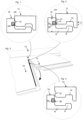
figures 1-4 . The locking of theshort edges flexible tongue 31 is displaced inwardly gradually from one edge to the other edge when a long side of apanel 1c in one row is connected by angling to anadjacent panel 1a in a previously installed row. The flexible snap tab, which in most cases is made of a plastic section, is during folding bended horizontally along the joint. A part of the snap tab is during folding almost in a locked position, as shown infigure 1 , and other parts are in contact with the adjacent edge,figure 2 , or in an completely unlocked position, as shown infigure 4 . - Some versions of flexible tongues which are generally made of an extruded plastic section have an inner part, which is connected in a
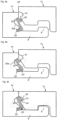
holding groove 32 and an outer flexible snap tab pointing downwards 33 that during folding snaps into atongue groove 31 of anadjacent panel 1c. The flexible tongue is generally connected to an edge of the strip panel. It could also be connected to the groove panel. The snap tab is in such a version extending upwards. - The main problem with know
flexible tongue 30 as shown infigure 2 is that it is difficult to lock due to limited flexibility. The contact point P between the groove panel and theflexible snap tab 33 is at an upper part when the groove panel is folded down along the vertical plane VP. The snap tab is also rather rigid due to the fact that the vertical extension T1 is less than 0.3 times the floor thickness T. The snap tab is also pushed inwardly and intersects the vertical plane VP. The holding groove must be made rather large in order to provide stability and this is a disadvantage. -
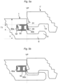
Figures 5a and 5b show a snap tab with improved flexibility. It has aninner part 30a and anouter part 30b that are flexible. The snap tab must be displaced in the holding groove during locking and this requires tight tolerances. The snap is displaced into theholding groove 32, which must have a considerable horizontally extending depth. -
Figures 6a and 6b show a locking system on the market where the contact point P is on the upper part of the flexible snap tab, which is displaced inwardly beyond the vertical plane in order to improve flexibility. The groove must be rather deep and this effect the stability of the edge in a negative way. -
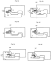
Figures 6c and 6d show another locking system on the market, which is made of three parts, two ratherrigid parts -
Figures 6e, 6f show a locking system with a simple cross section, which is schematically shown inWO 2007/079845 , figure 22, where theflexible snap tab 33 is made of a narrow rectangular cross-section that is bent or curved shaped. The snap tab is bended outside the vertical plane. The disadvantage is that the vertical extension of the holding groove is very small and difficult to produce with rotating tools. Theflexible tongue 30 is difficult to fix into the groove and has a limited flexibility. The main disadvantage is however that the snap tab is bent around a centre point CP that is in contact with the lower part of thegroove 32. This will in most cases cause a breaker or a permanent bending in many materials especially an extruded plastic material. The embodiment combines three major disadvantages: a) a deep holding groove, b) limited flexibility of the snap tab and c) high snapping resistance. - All the shown known embodiments have snap tabs, which have a vertical extension T1 that is smaller than 0.3 times the floor thickness T, and this creates a considerable snapping resistance during folding especially if it is combined with contacts points P at the upper part of the snap tab.
- The function of a locking system with a snap tab could be improved if flexibility of the snap tab could be increased and if the horizontal extension of the holding groove could be reduced.
- An objective of certain embodiments of the present invention is to provide an improved mechanical locking system comprising a flexible tongue with an outer flexible snap tab, which could by locked by vertical folding.
- More specifically the object is to provide a vertical snap locking system, which creates less snapping resistance and which has a more stable edge than the known systems.
- The objective is to improve the stability of the edge mainly with holding grooves that allow a strong connection between a flexible tongue and the holding groove and that have a smaller horizontal extension inwardly into the core of the panel than present known systems.
- The above objects of certain embodiments of the invention are achieved wholly or partly by a mechanical locking systems and floor panels, as described herein. Further embodiments of the invention are evident from the claims, description and drawings.
- According to a first aspect of certain embodiments of the disclosure, a set of floor panels are provided which are mechanically connectable to each other along one pair of adjacent edges, so that upper joint edges of said floor panels in the connected state define a vertical plane. Each of said floor panels comprising a flexible tongue on a first edge of the panel and a tongue groove on a second opposite edge of the panel for receiving the flexible tongue of an adjacent panel for mechanically locking together said adjacent edges vertically parallel to the vertical plane and at right angles to a horizontal plane of the panels.
- The tongue groove is formed in a core of the panel and is open towards the vertical plane. A locking element is formed in one piece with the panel at the first edge and a locking groove at the opposite second edge. The locking groove being open towards a rear side of the panel that faces a subfloor.
- The locking element and the locking groove form a horizontal mechanical connection perpendicular to the vertical plane, the locking element having a locking surface that is adapted to directly contact a locking surface of the locking groove for locking the panels to each other horizontally parallel to the horizontal plane and at right angles to the joined first and second edges.
- The flexible tongue comprises resilient parts formed of a separate material than the core, and cooperates with a locking surface in the tongue groove.
- Wherein two of the panels can be mechanically joined together by displacement of said two panels vertically towards each other, while at least an outer part of the flexible tongue, comprising a flexible snap tab extending downwards is resiliently displaced inwardly, substantially around a centre point located at an upper part of the flexible tongue and spaced from the lower part of the holding groove, to an inner position which is outside the vertical plane, until said adjacent edges of the two panels are brought into engagement with each other vertically and the flexible snap tab is displaced towards its initial position away from the vertical plane and against the tongue groove.
- The flexible tongue has an inner part mounted in a sideward open holding groove in the first edge that is open towards the vertical plane. The inner part is fixed in the sideward open holding groove.
- The outer flexible part, e.g., the flexible snap tab, has a cross section with a maximum thickness of the outer flexible part (e.g., the flexible snap tab), and the locking surface being offset in relation to the vertical plane by at least the maximum thickness of the flexible snap tab.
- According to a second aspect of certain embodiments of the disclosure, a set of floor panels are provided which are mechanically connectable to each other along one pair of adjacent edges, so that upper joint edges of said floor panels in the connected state define a vertical plane. Each of said floor panels comprising a flexible tongue on a first edge of the panel and a tongue groove on a second opposite edge of the panel for receiving the flexible tongue of an adjacent panel for mechanically locking together said adjacent edges vertically parallel to the vertical plane and at right angles to a horizontal plane of the panels.
- The tongue groove is formed in a core of the panel and is open towards the vertical plane. A locking element is formed in one piece with the panel at the first edge and a locking groove at the opposite second edge. The locking groove being open towards a rear side of the panel that faces a subfloor.
- The locking element and the locking groove form a horizontal mechanical connection perpendicular to the vertical plane, the locking element having a locking surface that is adapted to directly contact a locking surface of the locking groove for locking the panels to each other horizontally parallel to the horizontal plane and at right angles to the joined first and second edges.
- The flexible tongue comprises resilient parts formed of a separate material than the core, and cooperates with a locking surface in the tongue groove.
- Wherein two of the panels can be mechanically joined together by displacement of said two panels vertically towards each other, while at least an outer part of the flexible tongue, comprising a flexible snap tab extending downwards is resiliently displaced inwardly until said adjacent edges of the two panels are brought into engagement with each other vertically and the flexible snap tab is displaced towards its initial position away from the vertical plane and against the tongue groove.
- The flexible tongue has an inner part mounted in a sideward open holding groove in the first edge that is open towards the vertical plane. The inner part is fixed in the sideward open holding groove.
- The outer flexible part, e.g., the flexible snap tab, has a cross section with a maximum thickness of the outer flexible part (e.g., the flexible snap tab), and the locking surface being offset in relation to the vertical plane by at least the maximum thickness of the flexible snap tab.
- The inner part comprises one or several vertical cross sections wherein one of said vertical cross sections may be larger than said thickness of the flexible snap tab and/or another vertical cross section of the inner part.
- The invention is defined in the appended set of claims.
-
- Figs 1-6
- illustrate known systems.
- Figs 7a-c
- illustrate an embodiment of the invention.
- Figs 8a-d
- illustrate an embodiment of the disclosure.
- Figs 9a-c
- illustrate an embodiment of the disclosure.
- Figs 10a-c
- illustrate a flexible tongue fixed to an edge of the fold panel.
- Fig 10d
- illustrates a flexible tongue fixed in an inclined groove.
- To facilitate understanding, several locking systems in the figures are shown schematically. It should be emphasized that improved or different functions can be achieved using combinations of the preferred embodiments.
-
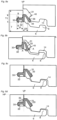
Figures 7a - 7c show an embodiment of the invention. Astrip panel 1b comprising astrip 6 and alocking element 8 which cooperates with a lockinggroove 14 in agroove panel 1c for horizontal locking of two adjacent edges ofpanels flexible tongue 30 in a holdinggroove 32, which is open towards the vertical plane VP and has an inner part IP connected to the holding groove. The flexible tongue has an outer part OP outside the vertical plane VP comprising aflexible snap tab 33 that cooperates with a lockingsurface 40 of atongue groove 31 in anadjacent edge 1c of thegroove panel 1c and locks the edges vertically parallel to the vertical plane VP. - The snap tab is during the whole locking motion positioned outside the vertical plane VP and is during locking displaced inwardly towards the vertical plane and outwardly away from the vertical plane as shown in
figures 7b and 7c . The snap tab is during the displacement bended around a centre point which is located at an upper part of theflexible tongue 30 and is spaced vertically upwards from the lower part of the holdinggroove 32 and preferably horizontally outwardly from the vertical plane VP. The snap tab is preferably spaced from the vertical plane in its inner position. The inner part of the snap tab could also preferably be aligned with the vertical pane. - Such an embodiment makes it possible to decrease the amount of material that has to be removed in order to form a holding groove. The horizontal extension of the holding
groove 32 could be decreased and even the opening could be smaller. This improves the stability of the edge. The improved stability could be combined with a maintained or even improved flexibility of the snap tab. - The
groove panel 1c comprises alower part 36, which is formed as a bevel, and more vertically inclined than theouter part 37 of the flexible snap tab. The first contact point P between thegroove panel 1c and theflexible tongue 30 is located at the lower part of theflexible snap tab 33 when thegroove panel 1c is displaced vertically along the vertical plane VP towards thestrip panel 1b. Such an embodiment will decrease the snapping resistance considerably. The lower part of the holdinggrove 32 is preferably located in a horizontal plane H1 which is vertically offset upwardly from a vertical plane H3 that intersects the upper part of thestrip 6 and preferably also from a horizontal plane H2 that intersects the upper part of the locking element. This facilitates the fixing of the tongue into the holding groove. The holding grove could also be inclined upwardly from an inner to an outer position. This is an advantage, which could be used in all snap tab systems, such as the known art systems previously discussed, to facilitate the fixing of the flexible tongue. Embodiments of the known art systems previously discussed with an inclined holding groove are included within the scope of the disclosure. - The flexible tongue has preferably a thickness A-A at its outer part OP that is smaller than a vertical thickness B-B located in the inner part IP. The inner part IP of the
flexible tongue 30 comprises preferably two vertical cross sections B-B, B'- B', with different vertical thicknesses and preferably aspace 39 between a lower and /or upper part of the flexible groove. Such an embodiment makes it possible to combine a stable connection of the flexible tongue, to save material and to improve flexibility. The lockingsurface 40 is offset to the vertical plane by at least the maximum thickness A-A of theflexible snap tab 33. - The inner part of the
flexible tongue 30 can substantially fill the volume of the sideward open holding groove or can comprise one orseveral friction connection 38 that extends downwards and /or upwards. - The described motion of a flexible snap tab outside the vertical plane and a first contact point at a lower part of the snap tab could be used separately to improve locking but preferably in combination. It is an advantage to use a low contact point even in embodiments where the snap tab is displaced inwardly beyond the vertical plane.
-
Figures 8a - 8c show that thesnap tab 33 could preferably be formed with a vertical extension T1 that is equal or larger than 0.3 times the floor thickness T. It is even more preferred to increase this vertical extension to 0.35 or even to more than 0.40 times the floor thickness T. This is especially preferable in wood floors where a high locking strength could be combined with an easy locking. - Such an embodiment could be used to decrease the locking resistance further especially if it is combined with one or both of the two other desired features described above.
-
Figure 8d shows an embodiment where theupper part 34 of theflexible tongue 30 can be bended horizontally inwardly, preferably to a position inside the vertical plane VP. When the upper part of the snap tab is in locked position, aspace 35 exists between the flexible tongue and the holdinggroove 32. The upper part of the flexible tongue is displaced in thespace 35 during locking. This can be used to reduce snapping resistance and to increase the flexibility of the flexible tongue. -
Figures 9a-9c show a preferred embodiment of aflexible tongue 30, which is connected in a fixed manner in a holdinggroove 32 of thestrip panel 1b and comprises aflexible part 33 that is displaceable in adisplacement groove 32a. Such an embodiment allows increased flexibility since the vertical distance between the lower part of the tongue that is connected in the holdinggroove 32 and theupper part 33 that locks against the lockingsurface 40 of thetongue groove 31, could be increased. - The
flexible snap tab 33 is during folding displaced horizontally inwards and outwards in thedisplacement groove 32a and bending occurs preferably and essentially around a centre point C located in a lower part of theflexible tongue 30. - The holding
groove 32 is located vertically below thedisplacement groove 32a. The lockingsurface 40 of thetongue groove 31 is preferably spaced vertically upwards in relation to the holdinggroove 32 and these two grooves are preferably located in different horizontal planes one over the other. The holdinggrove 32 is preferably located vertically below the upper part of thelocking element 8 and is preferably inclined upwards in relation to a horizontal plane in order to facilitate the insertion of theflexible tongue 31 into the holdinggroove 32. - Such a flexible tongue could also be connected to an edge of the
groove panel 1c. The holdinggroove 32 is in such an embodiment preferably located in the upper part of the panel edge and thedisplacement groove 32a below the holdinggroove 32. -
Figures 10a - 10c show that a flexible tongue could be connected to a holdinggroove 32 in thegroove panel 1c and that the holdinggroove 32 is spaced inwardly from the lockinggroove 14. The holdinggroove 32 could even in this embodiment preferably be inclined against the horizontal plane. -
Figures 10b and 10c show that theflexible snap tab 33 during locking slides against the upper andouter part 8a of thelocking element 8. Thispart 8a is in this embodiment inclined. It could for example also be rounded. Theouter part 33 of the snap tab locks against a lockingsurface 6a formed on the outer part of thestrip 6. - This locking
surface 6a could be inclined downwards or upward, essentially horizontal or rounded. -
Figure 10d shows that all embodiments shown infigures 7 and8 could be connected to a holdinggrove 32 that is inclined in order to facilitate the fixing of theflexible tongue 30 when a holdinggroove 32 is formed in thestrip panel 1b.
Claims (6)
- A set of floor panels (1b, 1c) which are mechanically connectable to each other along one pair of adjacent edges, so that upper joint edges of said floor panels in the connected state define a vertical plane (VP), each of said floor panels comprising:a flexible tongue (30) on a first edge of the panel (1b);a tongue groove (31) on a second opposite edge (1c) of the panel for receiving the flexible tongue of an adjacent panel for mechanically locking together said adjacent edges vertically parallel to the vertical plane (VP) and at right angles to a horizontal plane (HP) of the panels;the tongue groove (31) is formed in a core of the panel and is open towards the vertical plane;a locking element (8) formed in one piece with the panel at the first edge and a locking groove (14) at the opposite second edge, the locking groove being open towards a rear side of the panel that faces a subfloor;the locking element and the locking groove form a horizontal mechanical connection perpendicular to the vertical plane, the locking element having a locking surface that is adapted to directly contact a locking surface of the locking groove for locking the panels to each other horizontally parallel to the horizontal plane and at right angles to the joined first and second edges;the flexible tongue (30) comprising resilient parts formed of a separate material than the core, and cooperates with a locking surface (40) in the tongue groove (31);wherein two of the panels can be mechanically joined together by displacement of said two panels vertically towards each other, while at least an outer part (OP) of the flexible tongue, comprising a flexible snap tab (33) extending downwards is resiliently displaced inwardly to an inner position which is outside the vertical plane (VP) until said adjacent edges of the two panels are brought into engagement with each other vertically and the flexible snap tab (33) is displaced towards its initial position away from the vertical plane (VP) and against the tongue groove (31),wherein the flexible snap tab (33) is resiliently displaced inwardly substantially around a centre point (CP) located at an upper part of the flexible tongue (30) and spaced from the lower part of the holding groove (32).wherein the flexible tongue has an inner part (IP) mounted in a sideward open holding groove (32) in the first edge that is open towards the vertical plane (VP), the inner part (IP) is fixed in the sideward open holding groove (32),wherein the flexible snap tab has a cross section with a maximum thickness of the flexible snap tab and the locking surface (40) being offset in relation to the vertical plane (VP) by at least the maximum thickness (A-A) of the flexible snap tab (33),wherein the inner part (IP) comprises one or several vertical cross sections (B-B, B'-B') and wherein at least one of said vertical cross sections (B-B, B'-B') is larger than said thickness (A-A) of the flexible snap tab (33) and/or another vertical cross section (B-B, B'-B') in the inner part (IP), andwherein the second edge comprises a lower part (36) formed as a bevel,characterised in that the lower part (36) is more vertically inclined than an initial position of the snap tab (33) and the lower part of the second edge (36) and the flexible snap tab (33) are configured such that the first contact point (P) between the second edge and the flexible snap tab (33) is located at the lower part of said flexible snap tab (33) when the second edge (1c) is displaced along the vertical plane (VP) towards the first edge such that the snapping resistance is decreased
- The set of floor panels as claimed in claim 1, wherein there is a space (39) between the inner part (IP) of the flexible tongue (30) and the lower part of the holding groove (32).
- The set of floor panels as claimed in claim 1 or 2, wherein the snap tab (33) during locking is bended horizontally along the joint edge.
- The set of floor panels as claimed in any one of the claims 1-3 wherein the vertical extension (T1) of the snap tab is equal or larger than 0.3 times the floor panel thickness (T).
- The set of floor panels as claimed in any one of the preceding claims, wherein the flexible tongue (30) is made of extruded polymer material.
- The set of floor panels as claimed in any one of the preceding claims, wherein there is a space (35) between an upper part (34) of the flexible tongue and the holding groove and wherein the upper part (34) of the flexible tongue is displaced in said space during locking.
Applications Claiming Priority (3)
| Application Number | Priority Date | Filing Date | Title |
|---|---|---|---|
| SE1050018 | 2010-01-12 | ||
| EP10843344.2A EP2524093B1 (en) | 2010-01-12 | 2010-12-23 | Mechanical locking system for floor panels |
| PCT/SE2010/051479 WO2011087425A1 (en) | 2010-01-12 | 2010-12-23 | Mechanical locking system for floor panels |
Related Parent Applications (1)
| Application Number | Title | Priority Date | Filing Date |
|---|---|---|---|
| EP10843344.2A Division EP2524093B1 (en) | 2010-01-12 | 2010-12-23 | Mechanical locking system for floor panels |
Publications (2)
| Publication Number | Publication Date |
|---|---|
| EP3702549A1 EP3702549A1 (en) | 2020-09-02 |
| EP3702549B1 true EP3702549B1 (en) | 2023-05-10 |
Family
ID=44257406
Family Applications (2)
| Application Number | Title | Priority Date | Filing Date |
|---|---|---|---|
| EP10843344.2A Active EP2524093B1 (en) | 2010-01-12 | 2010-12-23 | Mechanical locking system for floor panels |
| EP20155317.9A Active EP3702549B1 (en) | 2010-01-12 | 2010-12-23 | Set of floor panels |
Family Applications Before (1)
| Application Number | Title | Priority Date | Filing Date |
|---|---|---|---|
| EP10843344.2A Active EP2524093B1 (en) | 2010-01-12 | 2010-12-23 | Mechanical locking system for floor panels |
Country Status (8)
| Country | Link |
|---|---|
| US (3) | US8544230B2 (en) |
| EP (2) | EP2524093B1 (en) |
| CN (1) | CN102695838B (en) |
| BR (2) | BR212012016569Y1 (en) |
| MY (1) | MY158334A (en) |
| PL (1) | PL2524093T3 (en) |
| RU (1) | RU2563005C2 (en) |
| WO (1) | WO2011087425A1 (en) |
Families Citing this family (132)
| Publication number | Priority date | Publication date | Assignee | Title |
|---|---|---|---|---|
| SE514645C2 (en) | 1998-10-06 | 2001-03-26 | Perstorp Flooring Ab | Floor covering material comprising disc-shaped floor elements intended to be joined by separate joint profiles |
| SE518184C2 (en) | 2000-03-31 | 2002-09-03 | Perstorp Flooring Ab | Floor covering material comprising disc-shaped floor elements which are joined together by means of interconnecting means |
| EP1495197B1 (en) | 2002-04-03 | 2010-05-05 | Välinge Innovation AB | Floorboard comprising integrated connecting means and a method for manufacturing the same |
| US7454875B2 (en) | 2004-10-22 | 2008-11-25 | Valinge Aluminium Ab | Mechanical locking system for floor panels |
| EP1936068B1 (en) | 2004-10-22 | 2011-11-30 | Välinge Innovation AB | A method of providing floor panels with a mechanical locking system |
| US7841144B2 (en) | 2005-03-30 | 2010-11-30 | Valinge Innovation Ab | Mechanical locking system for panels and method of installing same |
| BE1016938A6 (en) | 2005-03-31 | 2007-10-02 | Flooring Ind Ltd | Floor panel manufacturing method, involves providing panels at lower side with guiding groove and providing two opposite sides with profiled edge regions that comprise coupling parts |
| US20130139478A1 (en) | 2005-03-31 | 2013-06-06 | Flooring Industries Limited, Sarl | Methods for packaging floor panels, as well as packed set of floor panels |
| US8061104B2 (en) | 2005-05-20 | 2011-11-22 | Valinge Innovation Ab | Mechanical locking system for floor panels |
| SE530653C2 (en) | 2006-01-12 | 2008-07-29 | Vaelinge Innovation Ab | Moisture-proof floor board and floor with an elastic surface layer including a decorative groove |
| BE1017157A3 (en) | 2006-06-02 | 2008-03-04 | Flooring Ind Ltd | FLOOR COVERING, FLOOR ELEMENT AND METHOD FOR MANUFACTURING FLOOR ELEMENTS. |
| SE533410C2 (en) | 2006-07-11 | 2010-09-14 | Vaelinge Innovation Ab | Floor panels with mechanical locking systems with a flexible and slidable tongue as well as heavy therefore |
| US11725394B2 (en) | 2006-11-15 | 2023-08-15 | Välinge Innovation AB | Mechanical locking of floor panels with vertical folding |
| US8689512B2 (en) | 2006-11-15 | 2014-04-08 | Valinge Innovation Ab | Mechanical locking of floor panels with vertical folding |
| SE531111C2 (en) | 2006-12-08 | 2008-12-23 | Vaelinge Innovation Ab | Mechanical locking of floor panels |
| US8353140B2 (en) | 2007-11-07 | 2013-01-15 | Valinge Innovation Ab | Mechanical locking of floor panels with vertical snap folding |
| BE1018600A5 (en) | 2007-11-23 | 2011-04-05 | Flooring Ind Ltd Sarl | FLOOR PANEL. |
| AU2009226185B2 (en) | 2008-01-31 | 2015-04-16 | Valinge Innovation Ab | Mechanical locking of floor panels, methods to install and uninstall panels, a method and an equipment to produce the locking system, a method to connect a displaceable tongue to a panel and a tongue blank |
| US8112967B2 (en) | 2008-05-15 | 2012-02-14 | Valinge Innovation Ab | Mechanical locking of floor panels |
| BE1018627A5 (en) | 2009-01-16 | 2011-05-03 | Flooring Ind Ltd Sarl | FLOOR PANEL. |
| NZ593953A (en) * | 2009-01-30 | 2013-11-29 | Valinge Innovation Ab | Mechanical lockings of floor panels and a tongue blank |
| WO2011087425A1 (en) | 2010-01-12 | 2011-07-21 | Välinge Innovation AB | Mechanical locking system for floor panels |
| EP2524091B1 (en) * | 2010-01-14 | 2019-04-03 | Unilin, BVBA | Floor panel assembly |
| DE102010004717A1 (en) | 2010-01-15 | 2011-07-21 | Pergo (Europe) Ab | Set of panels comprising retaining profiles with a separate clip and method for introducing the clip |
| US8402707B2 (en) * | 2010-01-29 | 2013-03-26 | Royal Group Inc. | Interlocking panel system |
| MY159581A (en) | 2010-02-04 | 2017-01-13 | Vaelinge Innovation Ab | Mechanical locking system for floor panels |
| US8234830B2 (en) * | 2010-02-04 | 2012-08-07 | Välinge Innovations AB | Mechanical locking system for floor panels |
| DE212010000195U1 (en) | 2010-04-15 | 2012-08-06 | Spanolux N.V. Div. Balterio | Bottom plate arrangement |
| CN104775594B (en) | 2010-05-10 | 2017-09-22 | 佩尔戈(欧洲)股份公司 | Floor panel assembly |
| BE1019331A5 (en) | 2010-05-10 | 2012-06-05 | Flooring Ind Ltd Sarl | FLOOR PANEL AND METHODS FOR MANUFACTURING FLOOR PANELS. |
| PL2630316T3 (en) * | 2010-10-20 | 2018-02-28 | Kronoplus Technical Ag | Surface covering comprising laminate panels and an extraneous locking element |
| US8806832B2 (en) | 2011-03-18 | 2014-08-19 | Inotec Global Limited | Vertical joint system and associated surface covering system |
| UA109938C2 (en) | 2011-05-06 | 2015-10-26 | MECHANICAL LOCKING SYSTEM FOR CONSTRUCTION PANELS | |
| UA114715C2 (en) | 2011-07-05 | 2017-07-25 | Сералок Інновейшн Аб | Mechanical locking of floor panels with a glued tongue |
| US9725912B2 (en) | 2011-07-11 | 2017-08-08 | Ceraloc Innovation Ab | Mechanical locking system for floor panels |
| US8650826B2 (en) | 2011-07-19 | 2014-02-18 | Valinge Flooring Technology Ab | Mechanical locking system for floor panels |
| DE102012102339A1 (en) * | 2011-07-29 | 2013-01-31 | Hamberger Industriewerke Gmbh | Connection for elastic or plate-shaped components, profile slides and floor coverings |
| EP3623544B1 (en) * | 2011-08-15 | 2022-10-05 | Ceraloc Innovation AB | Mechanical locking system for floor panels |
| US8763340B2 (en) | 2011-08-15 | 2014-07-01 | Valinge Flooring Technology Ab | Mechanical locking system for floor panels |
| US8857126B2 (en) | 2011-08-15 | 2014-10-14 | Valinge Flooring Technology Ab | Mechanical locking system for floor panels |
| US8769905B2 (en) | 2011-08-15 | 2014-07-08 | Valinge Flooring Technology Ab | Mechanical locking system for floor panels |
| DE102012013742A1 (en) * | 2011-12-19 | 2013-06-20 | Fritz Egger Gmbh & Co. Og | Panel of a floor covering with foreign element |
| BE1020433A3 (en) * | 2012-01-05 | 2013-10-01 | Flooring Ind Ltd Sarl | PANEL. |
| PL3235971T3 (en) * | 2012-04-04 | 2019-03-29 | Välinge Innovation AB | Building panel with a mechanical locking system |
| US9216541B2 (en) | 2012-04-04 | 2015-12-22 | Valinge Innovation Ab | Method for producing a mechanical locking system for building panels |
| US8596013B2 (en) | 2012-04-04 | 2013-12-03 | Valinge Innovation Ab | Building panel with a mechanical locking system |
| US10035358B2 (en) | 2012-07-17 | 2018-07-31 | Ceraloc Innovation Ab | Panels with digital embossed in register surface |
| US9446602B2 (en) | 2012-07-26 | 2016-09-20 | Ceraloc Innovation Ab | Digital binder printing |
| LT2923012T (en) | 2012-11-22 | 2019-11-11 | Ceraloc Innovation Ab | Mechanical locking system for floor panels |
| US9371456B2 (en) | 2013-01-11 | 2016-06-21 | Ceraloc Innovation Ab | Digital thermal binder and powder printing |
| GB2538492A (en) | 2015-05-11 | 2016-11-23 | Cook Medical Technologies Llc | Aneurysm treatment assembly |
| US10041212B2 (en) | 2013-02-04 | 2018-08-07 | Ceraloc Innovation Ab | Digital overlay |
| US9194134B2 (en) | 2013-03-08 | 2015-11-24 | Valinge Innovation Ab | Building panels provided with a mechanical locking system |
| UA117479C2 (en) * | 2013-03-25 | 2018-08-10 | Велінге Інновейшн Аб | Floorboards provided with a mechanical locking system and a method to produce such a locking system |
| CA2913392C (en) | 2013-06-27 | 2022-01-18 | Valinge Innovation Ab | Building panel with a mechanical locking system |
| CN108252483A (en) * | 2013-07-09 | 2018-07-06 | 塞拉洛克创新股份有限公司 | For the mechanical locking system of floor panel |
| US9726210B2 (en) | 2013-09-16 | 2017-08-08 | Valinge Innovation Ab | Assembled product and a method of assembling the product |
| MY175374A (en) | 2013-09-16 | 2020-06-23 | Valinge Innovation Ab | An assembled product and a method of assembling the assembled product |
| WO2015070890A1 (en) * | 2013-11-12 | 2015-05-21 | Grigorij Wagner | Flooring component |
| US9714672B2 (en) | 2014-01-10 | 2017-07-25 | Valinge Innovation Ab | Panels comprising a mechanical locking device and an assembled product comprising the panels |
| EP3091872B1 (en) | 2014-01-10 | 2018-10-24 | Välinge Innovation AB | A furniture panel |
| PL3140555T3 (en) | 2014-05-09 | 2021-07-26 | Välinge Innovation AB | Mechanical locking system for building panels |
| EP3146126B1 (en) | 2014-05-14 | 2019-12-18 | Välinge Innovation AB | Set of two idencital panels with a mechanical locking system comprising a flexible tongue |
| US10246883B2 (en) * | 2014-05-14 | 2019-04-02 | Valinge Innovation Ab | Building panel with a mechanical locking system |
| US9752328B2 (en) | 2014-08-27 | 2017-09-05 | James Hardie Technology Limited | Cladding element |
| US11091917B2 (en) | 2014-08-27 | 2021-08-17 | James Hardie Technology Limited | Cladding element |
| MY183052A (en) | 2014-11-27 | 2021-02-09 | Valinge Innovation Ab | Mechanical locking system for floor panels |
| CA2971464A1 (en) * | 2014-12-19 | 2016-06-23 | Kinan KHATIB | Connection assembly between two components |
| EP3594514B1 (en) | 2014-12-19 | 2023-01-25 | Välinge Innovation AB | Panels comprising a mechanical locking device |
| CA2969191C (en) | 2014-12-22 | 2024-02-20 | Ceraloc Innovation Ab | Mechanical locking system for floor panels |
| EP3245352B1 (en) | 2015-01-15 | 2020-08-19 | Flooring Industries Limited, SARL | Floor panel for forming a floor covering |
| EP3247844B1 (en) | 2015-01-16 | 2022-03-16 | Ceraloc Innovation AB | Mechanical locking system for floor panels |
| US10670064B2 (en) | 2015-04-21 | 2020-06-02 | Valinge Innovation Ab | Panel with a slider |
| BR112017021806A2 (en) | 2015-04-30 | 2018-07-10 | Välinge Innovation AB | panel with a clamping device |
| AU2016327703B2 (en) | 2015-09-22 | 2020-09-03 | Välinge Innovation AB | Panels comprising a mechanical locking device and an assembled product comprising the panels |
| KR20180090838A (en) | 2015-12-03 | 2018-08-13 | 뵈린게 이노베이션 에이비이 | Panels comprising mechanical locks and assembled products containing such panels |
| DE102016114226A1 (en) * | 2016-01-22 | 2017-07-27 | Hamberger Industriewerke Gmbh | Connection for elastic or solid components |
| ES2866936T3 (en) | 2016-01-26 | 2021-10-20 | Vaelinge Innovation Ab | Panels comprising a mechanical interlocking device to obtain a furniture product |
| CA3011591A1 (en) | 2016-02-04 | 2017-08-10 | Valinge Innovation Ab | A set of panels for an assembled product |
| CA3011612A1 (en) | 2016-02-09 | 2017-08-17 | Valinge Innovation Ab | A set of three panel-shaped elements |
| JP6903673B2 (en) | 2016-02-09 | 2021-07-14 | ベーリンゲ、イノベイション、アクチボラグVaelinge Innovation Ab | How to make elements and decomposition grooves |
| CN108602198B (en) | 2016-02-15 | 2021-06-01 | 瓦林格创新股份有限公司 | Method of forming a panel for a furniture item |
| JP6935431B2 (en) | 2016-06-29 | 2021-09-15 | ベーリンゲ、イノベイション、アクチボラグVaelinge Innovation Ab | Tongue insertion method and device |
| WO2018004440A1 (en) | 2016-06-29 | 2018-01-04 | Välinge Innovation AB | A method and device for managing and separating a tongue from a tongue blank |
| CN109312566B (en) | 2016-06-29 | 2021-05-28 | 瓦林格创新股份有限公司 | Method and device for inserting a tongue |
| EP3478468B1 (en) | 2016-06-30 | 2021-05-26 | Välinge Innovation AB | Device for inserting a tongue |
| MY193824A (en) | 2016-10-27 | 2022-10-27 | Valinge Innovation Ab | Set of panels with a mechanical locking device |
| EP3558609B1 (en) | 2016-12-22 | 2021-10-20 | Välinge Innovation AB | Device for inserting a tongue into an insertion groove in a panel |
| EP3625464B1 (en) | 2017-05-15 | 2023-01-11 | Välinge Innovation AB | Elements and a locking device for an assembled product |
| UA125235C2 (en) * | 2017-07-18 | 2022-02-02 | Зайло Текнолоджіз Аґ | Panels with a detachable protruding lip for wall- ceiling- or floor coverings |
| USD850897S1 (en) | 2018-05-18 | 2019-06-11 | National Nail Corp. | Fastener positioning device |
| USD1019365S1 (en) | 2023-05-31 | 2024-03-26 | National Nail Corp. | Fastener positioning device |
| USD924044S1 (en) | 2019-11-20 | 2021-07-06 | National Nail Corp. | Fastener positioning device |
| US11898357B2 (en) | 2017-08-15 | 2024-02-13 | National Nail Corp. | Hidden fastener unit and related method of use |
| USD853829S1 (en) | 2018-06-01 | 2019-07-16 | National Nail Corp. | Fastener positioning device |
| US11261893B2 (en) | 2017-08-15 | 2022-03-01 | National Nail Corp. | Hidden fastener unit and related method of use |
| US11111679B2 (en) | 2017-08-15 | 2021-09-07 | National Nail Corp. | Hidden fastener unit and related method of use |
| US20210277668A1 (en) | 2017-08-15 | 2021-09-09 | National Nail Corp. | Hidden fastener unit and related method of use |
| US11149445B2 (en) | 2017-08-15 | 2021-10-19 | National Nail Corp. | Hidden fastener unit and related method of use |
| USD945870S1 (en) | 2020-11-17 | 2022-03-15 | National Nail Corp. | Fastener positioning device |
| US10378218B2 (en) | 2017-08-15 | 2019-08-13 | National Nail Corp. | Hidden fastener unit and related method of use |
| CN107724597B (en) * | 2017-09-22 | 2019-06-28 | 重庆工程职业技术学院 | A kind of assembled architecture wall |
| US10297796B2 (en) * | 2017-10-18 | 2019-05-21 | Wuhan China Star Optoelectronics Semiconductor Display Technology Co., Ltd. | Method of manufacturing OLED element and an OLED element |
| CN108001632A (en) * | 2017-12-14 | 2018-05-08 | 芜湖市皖南造船有限公司 | A kind of dredger living area composite floor board |
| BR112020012030B1 (en) | 2017-12-22 | 2023-11-21 | Välinge Innovation AB | PANEL SET |
| LT3728869T (en) | 2017-12-22 | 2023-04-25 | Välinge Innovation AB | A set of panels, a method for assembly of the same and a locking device for a furniture product |
| BE1026099B1 (en) * | 2018-03-16 | 2019-10-14 | Kreafin Group Sa | PANEL OF WHICH THE COUPLING DEVICES ARE SUITABLE FOR CONNECTING THE LONG SIDE AND / OR KOPSE SIDE TOGETHER |
| CN111629889B (en) * | 2018-01-22 | 2023-06-13 | 伊诺瓦默公司 | Method for producing a covering panel made of plastic and panel produced in this way |
| JP7221295B2 (en) | 2018-03-23 | 2023-02-13 | ベーリンゲ、イノベイション、アクチボラグ | Panels with mechanical locking devices and assembled products with panels |
| EP3781823B1 (en) | 2018-04-18 | 2024-04-10 | Välinge Innovation AB | Set of panels with a mechanical locking device |
| WO2019203723A1 (en) | 2018-04-18 | 2019-10-24 | Välinge Innovation AB | Set of panels with a mechanical locking device |
| CN112262265B (en) | 2018-04-18 | 2022-12-20 | 瓦林格创新股份有限公司 | Symmetrical tongue and T-shaped cross assembly |
| US11703072B2 (en) | 2018-04-18 | 2023-07-18 | Valinge Innovation Ab | Set of panels with a mechanical locking device |
| US11614114B2 (en) | 2018-04-19 | 2023-03-28 | Valinge Innovation Ab | Panels for an assembled product |
| CN108729576A (en) * | 2018-06-01 | 2018-11-02 | 俞昌书 | A kind of checkpost bone, middle card bone and its surface modifying systems |
| CN112639303A (en) | 2018-08-30 | 2021-04-09 | 瓦林格创新股份有限公司 | Panel assembly with mechanical locking device |
| USD850898S1 (en) | 2019-01-07 | 2019-06-11 | National Nail Corp. | Fastener positioning device |
| EP3908718A4 (en) | 2019-01-10 | 2022-10-12 | Välinge Innovation AB | Set of panels that can be vertically unlocked, a method and a device therefore |
| DE202019101807U1 (en) | 2019-03-29 | 2019-05-06 | Akzenta Paneele + Profile Gmbh | paneling |
| EP3718437A1 (en) | 2019-04-05 | 2020-10-07 | Välinge Innovation AB | Method for assembling a piece of furniture |
| CA3138206A1 (en) | 2019-06-28 | 2020-12-30 | James Hardie Technology Limited | Cladding element |
| EP3798386A1 (en) | 2019-09-24 | 2021-03-31 | Välinge Innovation AB | Set of panels with mechanically locking edges |
| EP4034732A4 (en) | 2019-09-25 | 2023-11-08 | Välinge Innovation AB | A set of panels comprising a flexing groove |
| WO2021059179A1 (en) | 2019-09-25 | 2021-04-01 | Välinge Innovation AB | Panel with locking device |
| EP4034733A4 (en) | 2019-09-25 | 2023-11-08 | Välinge Innovation AB | A set of panels comprising a flexing groove |
| CN115698447A (en) * | 2020-06-05 | 2023-02-03 | 瓦林格创新股份有限公司 | Building panel comprising a locking device |
| EP3971364A1 (en) | 2020-09-17 | 2022-03-23 | Surface Technologies GmbH & Co. KG | Panel |
| EP3971365A1 (en) | 2020-09-17 | 2022-03-23 | Surface Technologies GmbH & Co. KG | Panel |
| EP3971366A1 (en) * | 2020-09-17 | 2022-03-23 | Surface Technologies GmbH & Co. KG | Panel |
| CA3196815A1 (en) * | 2020-10-23 | 2022-04-28 | Valinge Innovation Ab | Building panel with first and second locking system |
| US11731252B2 (en) | 2021-01-29 | 2023-08-22 | National Nail Corp. | Screw guide and related method of use |
| USD1001321S1 (en) * | 2022-01-18 | 2023-10-10 | Irving Licensing Inc. | Interlockable board |
Family Cites Families (357)
| Publication number | Priority date | Publication date | Assignee | Title |
|---|---|---|---|---|
| US87853A (en) | 1869-03-16 | Improved mosaic floor | ||
| US213740A (en) * | 1879-04-01 | Improvement in wooden roofs | ||
| US124228A (en) | 1872-03-05 | Improvement in skate-fastenings | ||
| US108068A (en) | 1870-10-04 | Improvement in tiles for roofing | ||
| US274354A (en) | 1883-03-20 | Carthy | ||
| US316176A (en) | 1885-04-21 | Fbank h | ||
| US1194636A (en) * | 1916-08-15 | Silent door latch | ||
| US2732706A (en) | 1956-01-31 | Friedman | ||
| US634581A (en) * | 1898-11-21 | 1899-10-10 | Robert H Miller | Carpenter's square. |
| US861911A (en) | 1905-11-04 | 1907-07-30 | William Stewart | Joint for articles of furniture or woodwork. |
| SE57493C1 (en) | 1923-10-01 | 1924-09-16 | ||
| US1743492A (en) | 1927-08-02 | 1930-01-14 | Harry E Sipe | Resilient plug, dowel, and coupling pin |
| US1723306A (en) * | 1927-08-02 | 1929-08-06 | Harry E Sipe | Resilient attaching strip |
| US1809393A (en) | 1929-05-09 | 1931-06-09 | Byrd C Rockwell | Inlay floor construction |
| GB376352A (en) | 1931-04-10 | 1932-07-11 | Charles Harry Hart | Improvements in or relating to wood block floors |
| US1902716A (en) | 1931-09-08 | 1933-03-21 | Midland Creosoting Company | Flooring |
| US2026511A (en) | 1934-05-14 | 1935-12-31 | Storm George Freeman | Floor and process of laying the same |
| US2204675A (en) | 1937-09-29 | 1940-06-18 | Frank A Grunert | Flooring |
| US2266464A (en) | 1939-02-14 | 1941-12-16 | Gen Tire & Rubber Co | Yieldingly joined flooring |
| US2277758A (en) * | 1941-08-28 | 1942-03-31 | Frank J Hawkins | Shield |
| US2430200A (en) | 1944-11-18 | 1947-11-04 | Nina Mae Wilson | Lock joint |
| US2596280A (en) | 1947-03-21 | 1952-05-13 | Standard Railway Equipment Mfg | Metal covered walls |
| US2740167A (en) | 1952-09-05 | 1956-04-03 | John C Rowley | Interlocking parquet block |
| US2863185A (en) | 1954-02-16 | 1958-12-09 | Arnold T Riedi | Joint construction including a fastener for securing two structural members together in edge-to-edge closely abutting relation |
| US2858584A (en) | 1954-11-03 | 1958-11-04 | Eugene F Gaines | Spline for hanging tile |
| US2865058A (en) | 1955-04-12 | 1958-12-23 | Gustaf Kahr | Composite floors |
| US2889016A (en) * | 1955-04-13 | 1959-06-02 | Warren Jack | Chassis construction strip and a chassis |
| FR1138595A (en) | 1955-12-15 | 1957-06-17 | Tool for working with wooden heel blanks | |
| US3099110A (en) | 1957-09-17 | 1963-07-30 | Dur O Wal National Inc | Control joint |
| US3023681A (en) | 1958-04-21 | 1962-03-06 | Edoco Technical Products | Combined weakened plane joint former and waterstop |
| US3077703A (en) | 1959-04-17 | 1963-02-19 | Wood Conversion Co | Roof deck structure |
| US3147522A (en) * | 1960-06-01 | 1964-09-08 | Schumm Erich | Flexible tie |
| CH426190A (en) | 1963-12-23 | 1966-12-15 | Vilin Vertrieb Vissing & Linsm | Fixing device for wall and ceiling cladding |
| US3271787A (en) | 1964-04-06 | 1966-09-13 | Arthur L Clary | Resilient swimming pool coping |
| US3325585A (en) | 1966-03-15 | 1967-06-13 | John H Brenneman | Combined panel fastener and electrical conduit |
| US3396640A (en) | 1966-04-25 | 1968-08-13 | Grace W R & Co | Joint sealing devices |
| US3378958A (en) | 1966-09-21 | 1968-04-23 | Goodrich Co B F | Extrusions having integral portions of different stiffness |
| GB1171337A (en) | 1967-01-28 | 1969-11-19 | Transitoria Trading Company Ab | A Latching Means for Cupboard Doors, Locker Doors, Drawers and like Openable Members |
| US3512324A (en) | 1968-04-22 | 1970-05-19 | Lola L Reed | Portable sectional floor |
| US4037377A (en) | 1968-05-28 | 1977-07-26 | H. H. Robertson Company | Foamed-in-place double-skin building panel |
| US3517927A (en) | 1968-07-24 | 1970-06-30 | William Kennel | Helical spring bouncing device |
| US3572224A (en) | 1968-10-14 | 1971-03-23 | Kaiser Aluminium Chem Corp | Load supporting plank system |
| US3579941A (en) | 1968-11-19 | 1971-05-25 | Howard C Tibbals | Wood parquet block flooring unit |
| US3526071A (en) | 1969-02-17 | 1970-09-01 | Kogyo Gomu Co Ltd | Panel for curtain walls and method of jointing corners of the same |
| SE515210C2 (en) | 2000-04-10 | 2001-06-25 | Valinge Aluminium Ab | Locking systems for joining floorboards and floorboards provided with such locking systems and floors formed from such floorboards |
| SE515324C2 (en) | 2000-06-22 | 2001-07-16 | Tarkett Sommer Ab | Floor board with connecting means |
| US3760547A (en) | 1969-08-13 | 1973-09-25 | J Brenneman | Spline and seat connector assemblies |
| US3535844A (en) | 1969-10-30 | 1970-10-27 | Glaros Products Inc | Structural panels |
| DE2108141A1 (en) | 1970-02-20 | 1971-09-30 | Bruun & Soerensen A/S, Aarhus (Dänemark) | Floor construction |
| DE2021503A1 (en) | 1970-05-02 | 1971-11-25 | Freudenberg Carl Fa | Floor panels and methods of joining them |
| US3722379A (en) * | 1970-09-19 | 1973-03-27 | Mauer F Soehne | Method of constructing an expansion gap device and lost casing for such expansion gap |
| DE2111324C3 (en) | 1971-03-10 | 1979-07-05 | Migua-Mitteldeutsche Gummi Und Asbestgesellschaft Hammerschmidt & Co, 5628 Heiligenhaus | Device for sealing joints between components |
| GB1398709A (en) | 1971-07-12 | 1975-06-25 | Bpb Industries Ltd | Building panel |
| US3760548A (en) * | 1971-10-14 | 1973-09-25 | Armco Steel Corp | Building panel with adjustable telescoping interlocking joints |
| DE2159042C3 (en) | 1971-11-29 | 1974-04-18 | Heinrich 6700 Ludwigshafen Hebgen | Insulating board, in particular made of rigid plastic foam |
| US3778954A (en) | 1972-09-07 | 1973-12-18 | Johns Manville | Method of replacing a damaged bulkhead panel |
| US3919820A (en) | 1973-12-13 | 1975-11-18 | Johns Manville | Wall structure and device for sealing thereof |
| FR2256807A1 (en) | 1974-01-07 | 1975-08-01 | Merzeau Jean Alain | Woodworking tool forming slots - has multiple sets of toothed rotary cutters and spacers altered to vary spacing of slots |
| CA1012731A (en) | 1974-08-30 | 1977-06-28 | Beaconfield Consulting Services Limited | Attaching means for members at an angle to one another |
| AT341738B (en) | 1974-12-24 | 1978-02-27 | Hoesch Werke Ag | CONNECTING ELEMENT WITH SLOT AND SPRING CONNECTION |
| AR207658A1 (en) | 1975-07-15 | 1976-10-22 | Gen Tire & Rubber Co | REINFORCED ELASTOMERIC SEAL AND A METHOD OF MANUFACTURING IT |
| US4080086A (en) | 1975-09-24 | 1978-03-21 | Watson-Bowman Associates, Inc. | Roadway joint-sealing apparatus |
| US3994609A (en) | 1975-11-06 | 1976-11-30 | Acme Highway Products Corporation | Elastomeric expansion seal |
| GB1572696A (en) | 1975-11-22 | 1980-07-30 | Vredestein Nv | Injection-sealable water-stop and method of installing same |
| US4007994A (en) * | 1975-12-18 | 1977-02-15 | The D. S. Brown Company | Expansion joint with elastomer seal |
| US4169688A (en) * | 1976-03-15 | 1979-10-02 | Sato Toshio | Artificial skating-rink floor |
| USRE30154E (en) | 1976-09-02 | 1979-11-20 | Bose Corporation | Joining |
| US4064571A (en) | 1976-09-13 | 1977-12-27 | Timerax Holdings Ltd. | Pool liner retainer |
| US4082129A (en) | 1976-10-20 | 1978-04-04 | Morelock Donald L | Method and apparatus for shaping and planing boards |
| US4104840A (en) | 1977-01-10 | 1978-08-08 | Inryco, Inc. | Metal building panel |
| US4113399A (en) | 1977-03-02 | 1978-09-12 | Hansen Sr Wray C | Knob spring |
| US4107892A (en) | 1977-07-27 | 1978-08-22 | Butler Manufacturing Company | Wall panel unit |
| ES230786Y (en) | 1977-08-27 | 1978-03-16 | GASKET FOR ROOF PANELS. | |
| SE407174B (en) | 1978-06-30 | 1979-03-19 | Bahco Verktyg Ab | TURNING HAND TOOLS WITH SHAFT HALL ROOM FOR STORAGE OF TOOL ELEMENT |
| DE2828769A1 (en) | 1978-06-30 | 1980-01-03 | Oltmanns Heinrich Fa | BOX-SHAPED BUILDING BOARD MADE OF EXTRUDED PLASTIC |
| EP0013852A1 (en) | 1979-01-25 | 1980-08-06 | Claude Delfolie | Door consisting of slightly elastically deformable plastic profile members |
| US4426820A (en) | 1979-04-24 | 1984-01-24 | Heinz Terbrack | Panel for a composite surface and a method of assembling same |
| GB2051916A (en) | 1979-05-02 | 1981-01-21 | Ludford D | Structural Panels, Connectors Therefor and a Structure Erected Therefrom |
| US4304083A (en) | 1979-10-23 | 1981-12-08 | H. H. Robertson Company | Anchor element for panel joint |
| US4447172A (en) | 1982-03-18 | 1984-05-08 | Structural Accessories, Inc. | Roadway expansion joint and seal |
| DK149498C (en) | 1983-04-07 | 1986-12-01 | Inter Ikea As | CLOTHING OF BREADS FOR EX. FLOORS OR PANELS |
| US4512131A (en) | 1983-10-03 | 1985-04-23 | Laramore Larry W | Plank-type building system |
| DE3343601A1 (en) | 1983-12-02 | 1985-06-13 | Bütec Gesellschaft für bühnentechnische Einrichtungen mbH, 4010 Hilden | Joining arrangement for rectangular boards |
| US4648165A (en) * | 1984-11-09 | 1987-03-10 | Whitehorne Gary R | Metal frame (spring puller) |
| US4819932A (en) | 1986-02-28 | 1989-04-11 | Trotter Jr Phil | Aerobic exercise floor system |
| US5373674A (en) | 1987-04-27 | 1994-12-20 | Winter, Iv; Amos G. | Prefabricated building panel |
| US5135597A (en) | 1988-06-23 | 1992-08-04 | Weyerhaeuser Company | Process for remanufacturing wood boards |
| AU617969B2 (en) * | 1988-07-08 | 1991-12-05 | Sico Incorporated | Interlocking sections for portable floors and the like |
| US5007222A (en) * | 1988-11-14 | 1991-04-16 | Raymond Harry W | Foamed building panel including an internally mounted stud |
| US5071282A (en) | 1988-11-17 | 1991-12-10 | The D. S. Brown Company, Inc. | Highway expansion joint strip seal |
| US5247773A (en) | 1988-11-23 | 1993-09-28 | Weir Richard L | Building structures |
| US5148850A (en) | 1989-06-28 | 1992-09-22 | Paneltech Ltd. | Weatherproof continuous hinge connector for articulated vehicular overhead doors |
| DE3923427A1 (en) | 1989-07-15 | 1991-01-24 | Clouth Gummiwerke Ag | BODY SOUND INSULATING MAT |
| JPH03110258A (en) | 1989-09-25 | 1991-05-10 | Matsushita Electric Works Ltd | Structure of access floor |
| DE3932980A1 (en) | 1989-10-03 | 1991-11-28 | Hoelscher & Leuschner Gmbh | Plastic panels for emergency shelters - form walls, floors, roofs with edge grooves having recesses linked by separate barbed PVC connectors |
| US5026112A (en) | 1990-06-21 | 1991-06-25 | James S. Waldron | Truck trailer with removable side panels |
| US5348778A (en) | 1991-04-12 | 1994-09-20 | Bayer Aktiengesellschaft | Sandwich elements in the form of slabs, shells and the like |
| US5272850A (en) * | 1991-05-06 | 1993-12-28 | Icon, Incorporated | Panel connector |
| JPH0518028A (en) | 1991-07-15 | 1993-01-26 | Inax Corp | Coupling method for wall panel |
| US5182892A (en) | 1991-08-15 | 1993-02-02 | Louisiana-Pacific Corporation | Tongue and groove board product |
| US5344700A (en) | 1992-03-27 | 1994-09-06 | Aliquot, Ltd. | Structural panels and joint connector arrangement therefor |
| DE4215273C2 (en) | 1992-05-09 | 1996-01-25 | Dietmar Groeger | Covering for covering floor, wall and / or ceiling surfaces, in particular in the manner of a belt floor |
| US5634309A (en) | 1992-05-14 | 1997-06-03 | Polen; Rodney C. | Portable dance floor |
| US5295341A (en) | 1992-07-10 | 1994-03-22 | Nikken Seattle, Inc. | Snap-together flooring system |
| JP2550466B2 (en) | 1992-11-02 | 1996-11-06 | 大建工業株式会社 | Floor material |
| DE4242530C2 (en) | 1992-12-16 | 1996-09-12 | Walter Friedl | Building element for walls, ceilings or roofs of buildings |
| US5274979A (en) | 1992-12-22 | 1994-01-04 | Tsai Jui Hsing | Insulating plate unit |
| JP3060082B2 (en) | 1993-03-31 | 2000-07-04 | 西川ゴム工業株式会社 | Vibrantly colored architectural gaskets |
| JP2884993B2 (en) | 1993-04-23 | 1999-04-19 | 豊田合成株式会社 | Sealing material for wall panels |
| SE501014C2 (en) | 1993-05-10 | 1994-10-17 | Tony Pervan | Grout for thin liquid hard floors |
| US20020178674A1 (en) | 1993-05-10 | 2002-12-05 | Tony Pervan | System for joining a building board |
| US7121059B2 (en) | 1994-04-29 | 2006-10-17 | Valinge Innovation Ab | System for joining building panels |
| JPH06322848A (en) | 1993-05-11 | 1994-11-22 | Sekisui Chem Co Ltd | Waterproof structure of vertical outer wall joint |
| JPH0748879A (en) | 1993-08-05 | 1995-02-21 | Takeshige Shimonohara | Connecting method and connecting structure for member |
| US5598682A (en) | 1994-03-15 | 1997-02-04 | Haughian Sales Ltd. | Pipe retaining clip and method for installing radiant heat flooring |
| US5485702A (en) | 1994-03-25 | 1996-01-23 | Glenn Sholton | Mortarless glass block assembly |
| JP3461569B2 (en) | 1994-05-02 | 2003-10-27 | 大建工業株式会社 | Floor material |
| US5465546A (en) | 1994-05-04 | 1995-11-14 | Buse; Dale C. | Portable dance floor |
| US5502939A (en) | 1994-07-28 | 1996-04-02 | Elite Panel Products | Interlocking panels having flats for increased versatility |
| SE503917C2 (en) | 1995-01-30 | 1996-09-30 | Golvabia Ab | Device for joining by means of groove and chip of adjacent pieces of flooring material and a flooring material composed of a number of smaller pieces |
| US6421970B1 (en) | 1995-03-07 | 2002-07-23 | Perstorp Flooring Ab | Flooring panel or wall panel and use thereof |
| SE9500810D0 (en) | 1995-03-07 | 1995-03-07 | Perstorp Flooring Ab | Floor tile |
| US5618602A (en) | 1995-03-22 | 1997-04-08 | Wilsonart Int Inc | Articles with tongue and groove joint and method of making such a joint |
| US5577357A (en) | 1995-07-10 | 1996-11-26 | Civelli; Ken | Half log siding mounting system |
| JP3331424B2 (en) | 1995-10-31 | 2002-10-07 | ワイケイケイアーキテクチュラルプロダクツ株式会社 | Vertical frame reinforcement structure |
| US5755068A (en) | 1995-11-17 | 1998-05-26 | Ormiston; Fred I. | Veneer panels and method of making |
| BR7502683U (en) | 1995-11-24 | 1996-04-09 | Jacob Abrahams | Constructive arrangements in joints of strips for laminate floors or ceilings |
| US5658086A (en) * | 1995-11-24 | 1997-08-19 | Brokaw; Paul E. | Furniture connector |
| JP3954673B2 (en) | 1996-11-01 | 2007-08-08 | 株式会社ヤマックス | Joint for water stop of concrete joints |
| BE1010487A6 (en) | 1996-06-11 | 1998-10-06 | Unilin Beheer Bv | FLOOR COATING CONSISTING OF HARD FLOOR PANELS AND METHOD FOR MANUFACTURING SUCH FLOOR PANELS. |
| US5950389A (en) | 1996-07-02 | 1999-09-14 | Porter; William H. | Splines for joining panels |
| US6203653B1 (en) | 1996-09-18 | 2001-03-20 | Marc A. Seidner | Method of making engineered mouldings |
| US5694730A (en) | 1996-10-25 | 1997-12-09 | Noranda Inc. | Spline for joining boards |
| US6808777B2 (en) | 1996-11-08 | 2004-10-26 | Ab Golvabia | Flooring |
| SE507737C2 (en) | 1996-11-08 | 1998-07-06 | Golvabia Ab | Device for joining of flooring material |
| SE508165C2 (en) | 1996-11-18 | 1998-09-07 | Golvabia Ab | Device for joining of flooring material |
| US5857304A (en) | 1997-04-07 | 1999-01-12 | Abex Display Systems | Slidable locking system for disengageable panels |
| DE69730117T2 (en) | 1997-04-22 | 2005-09-01 | Mondo S.P.A., Gallo D'alba | Multi-layer flooring, especially for athletic equipment |
| AT405560B (en) | 1997-06-18 | 1999-09-27 | Kaindl M | ARRANGEMENT OF COMPONENTS AND COMPONENTS |
| IT237576Y1 (en) | 1997-07-11 | 2000-09-13 | Unifor Spa | PERFECTED CONNECTION SYSTEM BETWEEN MODULAR PANELS |
| US6345481B1 (en) | 1997-11-25 | 2002-02-12 | Premark Rwp Holdings, Inc. | Article with interlocking edges and covering product prepared therefrom |
| US6295779B1 (en) | 1997-11-26 | 2001-10-02 | Fred C. Canfield | Composite frame member and method of making the same |
| US5970675A (en) * | 1997-12-05 | 1999-10-26 | James D. Wright | Modular panel assembly |
| US6314701B1 (en) | 1998-02-09 | 2001-11-13 | Steven C. Meyerson | Construction panel and method |
| US6173548B1 (en) | 1998-05-20 | 2001-01-16 | Douglas J. Hamar | Portable multi-section activity floor and method of manufacture and installation |
| SE512313C2 (en) | 1998-06-03 | 2000-02-28 | Valinge Aluminium Ab | Locking system and floorboard |
| US7386963B2 (en) | 1998-06-03 | 2008-06-17 | Valinge Innovation Ab | Locking system and flooring board |
| SE512290C2 (en) | 1998-06-03 | 2000-02-28 | Valinge Aluminium Ab | Locking system for mechanical joining of floorboards and floorboard provided with the locking system |
| BE1012141A6 (en) | 1998-07-24 | 2000-05-02 | Unilin Beheer Bv | FLOOR COVERING, FLOOR PANEL THEREFOR AND METHOD for the realization of such floor panel. |
| SE514645C2 (en) | 1998-10-06 | 2001-03-26 | Perstorp Flooring Ab | Floor covering material comprising disc-shaped floor elements intended to be joined by separate joint profiles |
| SE515789C2 (en) | 1999-02-10 | 2001-10-08 | Perstorp Flooring Ab | Floor covering material comprising floor elements which are intended to be joined vertically |
| SE513189C2 (en) | 1998-10-06 | 2000-07-24 | Perstorp Flooring Ab | Vertically mountable floor covering material comprising sheet-shaped floor elements which are joined together by means of separate joint profiles |
| DE19940837A1 (en) | 1998-10-26 | 2000-11-23 | Karl Boeckl | Floor laying system comprises alignment elements and plate elements with cutouts which are dimensioned so that the alignment elements are easily slidable into their respective cutouts |
| AU2845900A (en) | 1999-01-07 | 2000-08-07 | Aviation Tectonics, Inc. | Fastening, bundling and closure device and dispensing arrangements therefor |
| US6254301B1 (en) | 1999-01-29 | 2001-07-03 | J. Melvon Hatch | Thermoset resin-fiber composites, woodworking dowels and other articles of manufacture made therefrom, and methods |
| DE19911379A1 (en) | 1999-03-15 | 2000-10-12 | Hekuma Herbst Maschinenbau Gmb | Cable ties and method of making cable ties |
| IL129834A (en) * | 1999-05-06 | 2001-09-13 | Ackerstein Ind Ltd | Ground surface cover system with flexible interlocking joint for erosion control |
| US6358352B1 (en) | 1999-06-25 | 2002-03-19 | Wyoming Sawmills, Inc. | Method for creating higher grade wood products from lower grade lumber |
| DE29911462U1 (en) | 1999-07-02 | 1999-11-18 | Akzenta Paneele & Profile Gmbh | Fastening system for panels |
| PT1190149E (en) | 1999-06-30 | 2005-01-31 | Akzenta Paneele & Profile Gmbh | PANEL WELL AS FIXING SYSTEM FOR PANELS |
| SE517009C2 (en) | 1999-07-05 | 2002-04-02 | Perstorp Flooring Ab | Floor element with controls |
| AT413227B (en) | 1999-07-23 | 2005-12-15 | Kaindl M | PANEL OR LUMINOUS COMPONENTS OR ARRANGEMENT WITH SUCH COMPONENTS AND CLAMPS HIEFÜR |
| US6449918B1 (en) * | 1999-11-08 | 2002-09-17 | Premark Rwp Holdings, Inc. | Multipanel floor system panel connector with seal |
| US7614197B2 (en) | 1999-11-08 | 2009-11-10 | Premark Rwp Holdings, Inc. | Laminate flooring |
| US20020194807A1 (en) | 1999-11-08 | 2002-12-26 | Nelson Thomas J. | Multipanel floor system with sealing elements |
| DE29920656U1 (en) | 1999-11-24 | 2000-02-17 | Vincent Irvin G | Universal component |
| DE19958225A1 (en) | 1999-12-03 | 2001-06-07 | Lindner Ag | Locking device for wall, ceiling or floor plates has lock sleeve engaging in bore on fixing part and containing magnetically displaceable element which spreads out sleeve to lock plate until released by magnetic force |
| US6761008B2 (en) | 1999-12-14 | 2004-07-13 | Mannington Mills, Inc. | Connecting system for surface coverings |
| US7169460B1 (en) | 1999-12-14 | 2007-01-30 | Mannington Mills, Inc. | Thermoplastic planks and methods for making the same |
| US6617009B1 (en) | 1999-12-14 | 2003-09-09 | Mannington Mills, Inc. | Thermoplastic planks and methods for making the same |
| AU3334501A (en) | 1999-12-22 | 2001-07-03 | Technique Arts And Design Inc. | Construction element and joining member |
| AU4743800A (en) | 1999-12-23 | 2001-07-09 | Hamberger Industriewerke Gmbh | Joint |
| US6332733B1 (en) | 1999-12-23 | 2001-12-25 | Hamberger Industriewerke Gmbh | Joint |
| EP1283313A1 (en) | 1999-12-27 | 2003-02-12 | Kronospan Technical Company Ltd. | Panel with a shaped plug-in section |
| DE29922649U1 (en) | 1999-12-27 | 2000-03-23 | Kronospan Tech Co Ltd | Panel with plug profile |
| DE20001788U1 (en) | 2000-02-02 | 2000-06-29 | Kronospan Tech Co Ltd | Panel with plug profile |
| DE10001076C1 (en) | 2000-01-13 | 2001-10-04 | Huelsta Werke Huels Kg | Panel element to construct floor covering; has groove and spring on opposite longitudinal sides and has groove and tongue on opposite end faces, to connect and secure adjacent panel elements |
| EP1120515A1 (en) | 2000-01-27 | 2001-08-01 | Triax N.V. | A combined set comprising a locking member and at least two building panels |
| SE522860C2 (en) | 2000-03-10 | 2004-03-09 | Pergo Europ Ab | Vertically joined floor elements comprising a combination of different floor elements |
| SE518184C2 (en) * | 2000-03-31 | 2002-09-03 | Perstorp Flooring Ab | Floor covering material comprising disc-shaped floor elements which are joined together by means of interconnecting means |
| US6363677B1 (en) | 2000-04-10 | 2002-04-02 | Mannington Mills, Inc. | Surface covering system and methods of installing same |
| US6553724B1 (en) | 2000-05-05 | 2003-04-29 | Robert A. Bigler | Panel and trade show booth made therefrom |
| AT411374B (en) | 2000-06-06 | 2003-12-29 | Kaindl M | COATING, COVERING OR THE LIKE, PANELS FOR ITS EDUCATION AND METHOD AND DEVICE FOR PRODUCING THE PANELS |
| FR2810060A1 (en) | 2000-06-08 | 2001-12-14 | Ykk France | Wooden floor paneling, for parquet floor, has elastic strip with lateral flanges forming stop faces for recessed surfaces on panels |
| DE10031639C2 (en) | 2000-06-29 | 2002-08-14 | Hw Ind Gmbh & Co Kg | Floor plate |
| US6339908B1 (en) | 2000-07-21 | 2002-01-22 | Fu-Ming Chuang | Wood floor board assembly |
| US6576079B1 (en) | 2000-09-28 | 2003-06-10 | Richard H. Kai | Wooden tiles and method for making the same |
| US7806624B2 (en) | 2000-09-29 | 2010-10-05 | Tripstop Technologies Pty Ltd | Pavement joint |
| US6546691B2 (en) | 2000-12-13 | 2003-04-15 | Kronospan Technical Company Ltd. | Method of laying panels |
| US6455712B1 (en) | 2000-12-13 | 2002-09-24 | Shell Oil Company | Preparation of oxirane compounds |
| ATE383480T1 (en) | 2001-01-12 | 2008-01-15 | Vaelinge Innovation Ab | FLOOR SYSTEM COMPRISING SEVERAL MECHANICALLY CONNECTABLE FLOOR PANELS |
| US6851241B2 (en) * | 2001-01-12 | 2005-02-08 | Valinge Aluminium Ab | Floorboards and methods for production and installation thereof |
| DE10101912C1 (en) | 2001-01-16 | 2002-03-14 | Johannes Schulte | Rectangular floor panel laying method uses fitting wedge for movement of floor panel in longitudinal and transverse directions for interlocking with adjacent floor panel and previous floor panel row |
| CA2331800A1 (en) | 2001-01-22 | 2002-07-22 | Moritz F. Gruber | Portable graphic floor system |
| DE10103505B4 (en) | 2001-01-26 | 2008-06-26 | Pergo (Europe) Ab | Floor or wall panel |
| SE520084C2 (en) | 2001-01-31 | 2003-05-20 | Pergo Europ Ab | Procedure for making merge profiles |
| US6854234B2 (en) | 2001-02-02 | 2005-02-15 | Skyline Displays, Inc. | Panel connector system |
| US6450235B1 (en) | 2001-02-09 | 2002-09-17 | Han-Sen Lee | Efficient, natural slat system |
| AT410815B (en) | 2001-04-05 | 2003-08-25 | Kaindl M | CONNECTION OF PANEL-SHAPED COMPONENTS |
| US20020170259A1 (en) | 2001-05-15 | 2002-11-21 | Ferris Stephen M. | Interlocking sidewalk block system |
| DE20109840U1 (en) | 2001-06-17 | 2001-09-06 | Kronospan Tech Co Ltd | Plates with push-in profile |
| EP1277896A1 (en) | 2001-07-16 | 2003-01-22 | Ulf Palmberg | Floorboards |
| SE519791C2 (en) | 2001-07-27 | 2003-04-08 | Valinge Aluminium Ab | System for forming a joint between two floorboards, floorboards therefore provided with sealing means at the joint edges and ways of manufacturing a core which is processed into floorboards |
| US8028486B2 (en) | 2001-07-27 | 2011-10-04 | Valinge Innovation Ab | Floor panel with sealing means |
| DE10138285A1 (en) | 2001-08-10 | 2003-03-06 | Akzenta Paneele & Profile Gmbh | Panel and fastening system for panels |
| SE525558C2 (en) | 2001-09-20 | 2005-03-08 | Vaelinge Innovation Ab | System for forming a floor covering, set of floorboards and method for manufacturing two different types of floorboards |
| US6651400B1 (en) | 2001-10-18 | 2003-11-25 | Rapid Displays, Inc. | Foam core panel connector |
| FR2831908B1 (en) | 2001-11-02 | 2004-10-22 | Europ De Laquage Et De Faconna | DEVICE FOR ASSEMBLING THE EDGES OF PANELS, SLATS OR PANELS |
| FR2832470B1 (en) | 2001-11-21 | 2006-10-20 | Grosfillex Sarl | PROFILE BLADE DEVICE |
| DE10159284B4 (en) | 2001-12-04 | 2005-04-21 | Kronotec Ag | Building plate, in particular floor panel |
| US7108031B1 (en) | 2002-01-31 | 2006-09-19 | David Secrest | Method of making patterns in wood and decorative articles of wood made from said method |
| DE10206877B4 (en) | 2002-02-18 | 2004-02-05 | E.F.P. Floor Products Fussböden GmbH | Panel, especially floor panel |
| AU2002254932A1 (en) | 2002-03-07 | 2003-09-16 | Fritz Egger Gmbh And Co. | Panels provided with a friction-based fixing |
| EP1495197B1 (en) | 2002-04-03 | 2010-05-05 | Välinge Innovation AB | Floorboard comprising integrated connecting means and a method for manufacturing the same |
| DE20220655U1 (en) | 2002-04-04 | 2004-01-08 | Akzenta Paneele + Profile Gmbh | Locking system for panels with edge profiles, has groove profile and tongue profile which are engaged to form articulated joint that restores two panels to their installation plane when deflected either up or down |
| DE50311595D1 (en) | 2002-04-05 | 2009-07-30 | Tilo Gmbh | Floor boards |
| DE20205774U1 (en) | 2002-04-13 | 2002-08-14 | Kronospan Tech Co Ltd | Panels with rubberized edging |
| ATE488655T1 (en) | 2002-04-13 | 2010-12-15 | Kronoplus Technical Ag | PANELS WITH BORDER AND INSTALLATION AID |
| US7051486B2 (en) | 2002-04-15 | 2006-05-30 | Valinge Aluminium Ab | Mechanical locking system for floating floor |
| US7739849B2 (en) | 2002-04-22 | 2010-06-22 | Valinge Innovation Ab | Floorboards, flooring systems and methods for manufacturing and installation thereof |
| BR0309248B1 (en) | 2002-04-22 | 2013-04-02 | floor comprising rectangular floorboards with a laminate surface to provide a standard floating floor. | |
| DE10233731A1 (en) * | 2002-07-24 | 2004-04-08 | M. Kaindl | Arrangement of components with connecting elements |
| DE10237397A1 (en) | 2002-08-09 | 2004-02-19 | Profilex Ag | Method for edge joining flat panels has profiled grooves in the adjoining edges gripped by an elastic profile with at least one grip section which cannot be released by external force |
| AT413228B (en) | 2002-08-19 | 2005-12-15 | Kaindl M | COVER PLATE |
| US6792727B2 (en) | 2002-09-12 | 2004-09-21 | Commercial And Architectural Products, Inc. | Curved wall panel system |
| DE10243196B4 (en) | 2002-09-18 | 2007-03-22 | Kaindl Flooring Gmbh | Panels with connection bracket |
| US7617651B2 (en) | 2002-11-12 | 2009-11-17 | Kronotec Ag | Floor panel |
| ATE395481T1 (en) | 2002-11-15 | 2008-05-15 | Flooring Technologies Ltd | DEVICE CONSISTS OF TWO BUILDING PLATES THAT CAN BE CONNECTED TO EACH OTHER AND AN INSERT FOR LOCKING THESE BUILDING PLATES |
| BE1015223A3 (en) | 2002-11-25 | 2004-11-09 | Flooring Ind Ltd | Floor panel, covering it formed, method for the installation of such floor panels and method for manufacturing same. |
| DE10318093A1 (en) | 2002-12-02 | 2004-06-17 | Kronospan Ag | Process for gluing an element |
| SE525622C2 (en) | 2002-12-09 | 2005-03-22 | Pergo Europ Ab | Procedure for installation of panels with joints, encapsulated agent and glue |
| DE20320022U1 (en) | 2003-01-09 | 2004-04-01 | Flooring Industries Ltd. | Set of floor panels to form a floor covering |
| US7533500B2 (en) | 2003-01-27 | 2009-05-19 | Deceuninck North America, Llc | Deck plank and method of production |
| US6948716B2 (en) * | 2003-03-03 | 2005-09-27 | Drouin Gerard | Waterstop having improved water and moisture sealing features |
| US7845140B2 (en) | 2003-03-06 | 2010-12-07 | Valinge Innovation Ab | Flooring and method for installation and manufacturing thereof |
| US7677001B2 (en) | 2003-03-06 | 2010-03-16 | Valinge Innovation Ab | Flooring systems and methods for installation |
| ATE557149T1 (en) | 2003-03-06 | 2012-05-15 | Vaelinge Innovation Ab | FLOORING SYSTEMS AND INSTALLATION PROCEDURES |
| WO2004079129A1 (en) | 2003-03-07 | 2004-09-16 | Akzo Nobel Coatings International B.V. | Interlocking unit |
| AT501440A1 (en) | 2003-03-07 | 2006-09-15 | Kaindl Flooring Gmbh | COVER PLATE |
| SE0300642D0 (en) * | 2003-03-11 | 2003-03-11 | Pergo Europ Ab | Process for sealing a joint |
| SE526691C2 (en) * | 2003-03-18 | 2005-10-25 | Pergo Europ Ab | Panel joint with friction raising means at longitudinal side joint |
| DE10313112B4 (en) | 2003-03-24 | 2007-05-03 | Fritz Egger Gmbh & Co. | Covering with a plurality of panels, in particular floor covering, and method for laying panels |
| DE20304761U1 (en) | 2003-03-24 | 2004-04-08 | Kronotec Ag | Device for connecting building boards, in particular floor panels |
| US7152383B1 (en) | 2003-04-10 | 2006-12-26 | Eps Specialties Ltd., Inc. | Joining of foam core panels |
| DE10329686B4 (en) | 2003-07-02 | 2008-02-28 | Akzenta Paneele + Profile Gmbh | Panel with locking system |
| EP1639215B1 (en) | 2003-07-02 | 2011-06-15 | Interglarion Limited | Panels comprising interlocking snap-in profiles |
| KR100566083B1 (en) | 2003-08-07 | 2006-03-30 | 주식회사 한솔홈데코 | Sectional floorings |
| DE20313661U1 (en) | 2003-09-05 | 2003-11-13 | Kaindl Wals M | Panel with protected V-groove |
| SE526688C2 (en) | 2003-11-20 | 2005-10-25 | Pergo Europ Ab | Method of joining panels where a locking rod is inserted into a locking groove or locking cavity |
| SE526179C2 (en) | 2003-12-02 | 2005-07-19 | Vaelinge Innovation Ab | Flooring and method of laying |
| US7886497B2 (en) | 2003-12-02 | 2011-02-15 | Valinge Innovation Ab | Floorboard, system and method for forming a flooring, and a flooring formed thereof |
| DE102004001363A1 (en) | 2004-01-07 | 2005-08-04 | Hamberger Industriewerke Gmbh | Floor units interconnection, has panel with interlocking projection having spring blade, which lies in interlocked position with abutting face of active surface of vertical interlocking projection |
| US7516588B2 (en) | 2004-01-13 | 2009-04-14 | Valinge Aluminium Ab | Floor covering and locking systems |
| DE102005002297A1 (en) | 2004-01-16 | 2005-08-04 | Hamberger Industriewerke Gmbh | Tile-shaped building parts e.g. laminated floor tiles, joint, has devices for horizontal and vertical interlocking, which is provided along part`s leading edges formed independent of elasticity of materials with which parts are made |
| DE202004001037U1 (en) | 2004-01-24 | 2004-04-29 | Kronotec Ag | Panel, in particular floor panel |
| DE102004005047B3 (en) | 2004-01-30 | 2005-10-20 | Kronotec Ag | Method and device for introducing a strip forming the spring of a plate |
| US7556849B2 (en) | 2004-03-25 | 2009-07-07 | Johns Manville | Low odor faced insulation assembly |
| US7219392B2 (en) | 2004-06-28 | 2007-05-22 | Wayne-Dalton Corp. | Breakaway track system for an overhead door |
| BE1016216A5 (en) | 2004-09-24 | 2006-05-02 | Flooring Ind Ltd | FLOOR PANEL AND FLOOR COVERING COMPOSED OF SUCH FLOOR PANELS. |
| EP1936068B1 (en) | 2004-10-22 | 2011-11-30 | Välinge Innovation AB | A method of providing floor panels with a mechanical locking system |
| US7454875B2 (en) | 2004-10-22 | 2008-11-25 | Valinge Aluminium Ab | Mechanical locking system for floor panels |
| US7841144B2 (en) | 2005-03-30 | 2010-11-30 | Valinge Innovation Ab | Mechanical locking system for panels and method of installing same |
| DE102004054368A1 (en) | 2004-11-10 | 2006-05-11 | Kaindl Flooring Gmbh | trim panel |
| US20060174577A1 (en) | 2005-01-27 | 2006-08-10 | O'neil John P | Hidden stiffening panel connector and connecting method |
| US20060179754A1 (en) | 2005-02-02 | 2006-08-17 | Feng-Ling Yang | Combinable floor plate |
| US8061104B2 (en) | 2005-05-20 | 2011-11-22 | Valinge Innovation Ab | Mechanical locking system for floor panels |
| DE102005024366A1 (en) | 2005-05-27 | 2006-11-30 | Kaindl Flooring Gmbh | Method for laying and mechanically connecting panels |
| SE529076C2 (en) | 2005-07-11 | 2007-04-24 | Pergo Europ Ab | A joint for panels |
| CA2618496C (en) | 2005-08-16 | 2010-02-09 | Johannes Schulte | Method for production of panels |
| DE102005038975B3 (en) | 2005-08-16 | 2006-12-14 | Johannes Schulte | Panel production process for floor, wall or ceiling panels has initial board with parallel grooves in upper and lower surfaces |
| DE102005054725A1 (en) | 2005-11-17 | 2007-05-24 | Agro Federkernproduktions Gmbh | innerspring |
| US20070151189A1 (en) | 2006-01-03 | 2007-07-05 | Feng-Ling Yang | Securing device for combining floor plates |
| US8464489B2 (en) | 2006-01-12 | 2013-06-18 | Valinge Innovation Ab | Laminate floor panels |
| SE530653C2 (en) | 2006-01-12 | 2008-07-29 | Vaelinge Innovation Ab | Moisture-proof floor board and floor with an elastic surface layer including a decorative groove |
| DE102006011887A1 (en) | 2006-01-13 | 2007-07-19 | Akzenta Paneele + Profile Gmbh | Blocking element, panel with separate blocking element, method of installing a panel covering of panels with blocking elements, and method and device for pre-assembling a blocking element on a panel |
| SE529506C2 (en) | 2006-02-03 | 2007-08-28 | Pergo Europ Ab | A joint cover for panels |
| CA2576889A1 (en) | 2006-02-06 | 2007-08-06 | Insca Internacional, S.L. | Device for joining parquet-type plaques or pieces |
| DE102006006124A1 (en) * | 2006-02-10 | 2007-08-23 | Flooring Technologies Ltd. | Device for locking two building panels |
| WO2007106352A2 (en) | 2006-03-10 | 2007-09-20 | Mannington Mills, Inc. | A process and system for sub-dividing a laminated flooring substrate |
| ES2574671T3 (en) | 2006-04-14 | 2016-06-21 | Yekalon Industry Inc. | A floor block, a flooring system and a corresponding placement procedure |
| DE102006024184A1 (en) | 2006-05-23 | 2007-11-29 | Hipper, August, Dipl.-Ing. (FH) | Connection for panel boards forms a groove/spring connection along edges to be connected so as to fix in a vertical direction |
| BE1017157A3 (en) * | 2006-06-02 | 2008-03-04 | Flooring Ind Ltd | FLOOR COVERING, FLOOR ELEMENT AND METHOD FOR MANUFACTURING FLOOR ELEMENTS. |
| SE530048C2 (en) | 2006-06-09 | 2008-02-19 | Burseryd Innovation Ab | Fasteners and method of joining dynamic bodies by means of the fastener |
| SE533410C2 (en) | 2006-07-11 | 2010-09-14 | Vaelinge Innovation Ab | Floor panels with mechanical locking systems with a flexible and slidable tongue as well as heavy therefore |
| US7861482B2 (en) | 2006-07-14 | 2011-01-04 | Valinge Innovation Ab | Locking system comprising a combination lock for panels |
| US7654055B2 (en) * | 2006-08-08 | 2010-02-02 | Ricker Michael B | Glueless panel locking system |
| DE102006037614B3 (en) | 2006-08-10 | 2007-12-20 | Guido Schulte | Floor covering, has head spring pre-assembled in slot and protruding over end of slot, and wedge surface formed at slot or head spring such that head spring runs into wedge surface by shifting projecting end of head spring into slot |
| US7257926B1 (en) * | 2006-08-24 | 2007-08-21 | Kirby Mark E | Tile spacer and leveler |
| EP2082103B1 (en) | 2006-11-15 | 2012-12-19 | Välinge Innovation AB | An installation method to connect floor panels in rows by vertical folding |
| US8689512B2 (en) | 2006-11-15 | 2014-04-08 | Valinge Innovation Ab | Mechanical locking of floor panels with vertical folding |
| DE102006057491A1 (en) * | 2006-12-06 | 2008-06-12 | Akzenta Paneele + Profile Gmbh | Panel and flooring |
| SE531111C2 (en) | 2006-12-08 | 2008-12-23 | Vaelinge Innovation Ab | Mechanical locking of floor panels |
| DE202007019298U1 (en) | 2007-02-21 | 2011-10-19 | Hamberger Industriewerke Gmbh | Connection for plate-shaped components |
| SE532207C2 (en) | 2007-03-14 | 2009-11-17 | Kaehr Ab G | Floor-laying system, profile rail and floor-board for such floor-laying system Procedure for laying conduit elements in the floor-laying system as well as uses of the floor-laying system for various purposes |
| DE202007018662U1 (en) | 2007-03-26 | 2009-02-19 | Kronotec Ag | Panel, in particular floor panel |
| DE102007016533A1 (en) | 2007-04-05 | 2008-10-09 | Hülsta-Werke Hüls Gmbh & Co. Kg | Floor, wall or ceiling panels and method for connecting floor, wall or ceiling panels |
| DE102007017087B4 (en) | 2007-04-10 | 2009-06-25 | Kronotec Ag | Panel, in particular floor panel |
| DE102007026342B4 (en) | 2007-06-06 | 2013-11-28 | Laminatepark Gmbh & Co. Kg | Set of tabular panels with movable locking element |
| DE102007032885B4 (en) | 2007-07-14 | 2016-01-14 | Flooring Technologies Ltd. | Panel, in particular floor panel and means for locking interconnected panels |
| US8220217B2 (en) | 2007-07-20 | 2012-07-17 | Innovaris Ag | Flooring system |
| US7726088B2 (en) | 2007-07-20 | 2010-06-01 | Moritz Andre Muehlebach | Flooring system |
| DE102007035648A1 (en) | 2007-07-27 | 2009-01-29 | Agepan-Tarkett Laminatepark Eiweiler Gmbh & Co. Kg | Board-like panel used as a floor panel comprises a locking element fixed to a holding profile by inserting or sliding |
| DE102007049792A1 (en) | 2007-08-10 | 2009-02-19 | Hamberger Industriewerke Gmbh | connection |
| DE102007042250B4 (en) | 2007-09-06 | 2010-04-22 | Flooring Technologies Ltd. | Device for connecting and locking two building panels, in particular floor panels |
| DE102007043308B4 (en) | 2007-09-11 | 2009-12-03 | Flooring Technologies Ltd. | Device for connecting and locking two building panels, in particular floor panels |
| US8353140B2 (en) | 2007-11-07 | 2013-01-15 | Valinge Innovation Ab | Mechanical locking of floor panels with vertical snap folding |
| PL2235286T3 (en) | 2007-11-07 | 2019-07-31 | Välinge Innovation AB | Mechanical locking of floor panels with vertical snap folding and an installation method to connect such panels |
| BE1018600A5 (en) | 2007-11-23 | 2011-04-05 | Flooring Ind Ltd Sarl | FLOOR PANEL. |
| US7805903B2 (en) * | 2007-12-13 | 2010-10-05 | Liu David C | Locking mechanism for flooring boards |
| DE102008003550B4 (en) | 2008-01-09 | 2009-10-22 | Flooring Technologies Ltd. | Device and method for locking two floor panels |
| US8505257B2 (en) | 2008-01-31 | 2013-08-13 | Valinge Innovation Ab | Mechanical locking of floor panels |
| AU2009226185B2 (en) | 2008-01-31 | 2015-04-16 | Valinge Innovation Ab | Mechanical locking of floor panels, methods to install and uninstall panels, a method and an equipment to produce the locking system, a method to connect a displaceable tongue to a panel and a tongue blank |
| US20090241460A1 (en) | 2008-03-26 | 2009-10-01 | Charles Beaulieu | Fastening Device Template |
| US8112967B2 (en) * | 2008-05-15 | 2012-02-14 | Valinge Innovation Ab | Mechanical locking of floor panels |
| DE102008031167B4 (en) | 2008-07-03 | 2015-07-09 | Flooring Technologies Ltd. | Method for connecting and locking glueless laying floor panels |
| WO2010042182A1 (en) * | 2008-10-08 | 2010-04-15 | Armstrong World Industries, Inc. | Flooring panel with first and second decorative surfaces |
| BE1018389A3 (en) | 2008-12-17 | 2010-10-05 | Unilin Bvba | COMPOSITE ELEMENT, MULTI-LAYER PLATE AND PANEL-SHAPED ELEMENT FOR FORMING SUCH COMPOSITE ELEMENT. |
| US7998549B2 (en) | 2009-01-08 | 2011-08-16 | Thermwood Corporation | Structure and method of assembly thereof |
| BE1018627A5 (en) | 2009-01-16 | 2011-05-03 | Flooring Ind Ltd Sarl | FLOOR PANEL. |
| NZ593953A (en) | 2009-01-30 | 2013-11-29 | Valinge Innovation Ab | Mechanical lockings of floor panels and a tongue blank |
| EP2236694A1 (en) | 2009-03-25 | 2010-10-06 | Spanolux N.V.- DIV. Balterio | A fastening system and a panel |
| DE102009022483A1 (en) | 2009-05-25 | 2010-12-02 | Pergo (Europe) Ab | Set of panels, in particular floor panels |
| DE102009035275A1 (en) | 2009-06-08 | 2010-12-09 | Fritz Egger Gmbh & Co. | Panel of a floor system |
| BE1018802A3 (en) | 2009-06-29 | 2011-09-06 | Flooring Ind Ltd Sarl | PANEL, MORE SPECIAL FLOOR PANEL. |
| TWM373948U (en) * | 2009-07-22 | 2010-02-11 | Feng-Ling Yang | Assembly floor |
| DE102009034902B4 (en) | 2009-07-27 | 2015-10-01 | Guido Schulte | Surface made of mechanically interconnectable panels |
| US8322104B2 (en) | 2009-08-31 | 2012-12-04 | Fleming Iii Joseph C | Method and system for interconnecting structural panels |
| DE102009041297B4 (en) * | 2009-09-15 | 2018-10-11 | Guido Schulte | Coating of mechanically interconnectable elements and a process for the production of elements |
| CN201588375U (en) | 2009-09-29 | 2010-09-22 | 钟玉东 | Embedded type combined solid wood flooring |
| DE102009048050B3 (en) | 2009-10-02 | 2011-01-20 | Guido Schulte | Surface made of mechanical interconnectable elements |
| US8429870B2 (en) * | 2009-12-04 | 2013-04-30 | Mannington Mills, Inc. | Connecting system for surface coverings |
| WO2011087425A1 (en) | 2010-01-12 | 2011-07-21 | Välinge Innovation AB | Mechanical locking system for floor panels |
| DE102010004717A1 (en) | 2010-01-15 | 2011-07-21 | Pergo (Europe) Ab | Set of panels comprising retaining profiles with a separate clip and method for introducing the clip |
| US8234830B2 (en) | 2010-02-04 | 2012-08-07 | Välinge Innovations AB | Mechanical locking system for floor panels |
| MY159581A (en) | 2010-02-04 | 2017-01-13 | Vaelinge Innovation Ab | Mechanical locking system for floor panels |
| US20110197635A1 (en) * | 2010-02-12 | 2011-08-18 | Mcdermott Braden A | Optimized Scoop for Improved Gob Shape |
| US20110197535A1 (en) | 2010-02-13 | 2011-08-18 | Geoffrey Alan Baker | Laying and mechanically joining building panels or construction elements |
| DE212010000195U1 (en) | 2010-04-15 | 2012-08-06 | Spanolux N.V. Div. Balterio | Bottom plate arrangement |
| CN102917616B (en) | 2010-06-03 | 2017-02-08 | 尤尼林有限公司 | Composed element and corner connection applied herewith |
| PL2630316T3 (en) | 2010-10-20 | 2018-02-28 | Kronoplus Technical Ag | Surface covering comprising laminate panels and an extraneous locking element |
| UA109938C2 (en) * | 2011-05-06 | 2015-10-26 | MECHANICAL LOCKING SYSTEM FOR CONSTRUCTION PANELS | |
| UA114715C2 (en) | 2011-07-05 | 2017-07-25 | Сералок Інновейшн Аб | Mechanical locking of floor panels with a glued tongue |
| US9725912B2 (en) | 2011-07-11 | 2017-08-08 | Ceraloc Innovation Ab | Mechanical locking system for floor panels |
| US8650826B2 (en) | 2011-07-19 | 2014-02-18 | Valinge Flooring Technology Ab | Mechanical locking system for floor panels |
| US8769905B2 (en) | 2011-08-15 | 2014-07-08 | Valinge Flooring Technology Ab | Mechanical locking system for floor panels |
| US8857126B2 (en) | 2011-08-15 | 2014-10-14 | Valinge Flooring Technology Ab | Mechanical locking system for floor panels |
| US8763340B2 (en) | 2011-08-15 | 2014-07-01 | Valinge Flooring Technology Ab | Mechanical locking system for floor panels |
| BR112014003962B1 (en) | 2011-08-29 | 2021-04-13 | Ceraloc Innovation Ab | FLOOR PANELS PROVIDED WITH A LOCKING SYSTEM |
| DE102011056494A1 (en) | 2011-12-15 | 2013-06-20 | Pergo (Europe) Ab | Set of panels with clip |
| US8596013B2 (en) | 2012-04-04 | 2013-12-03 | Valinge Innovation Ab | Building panel with a mechanical locking system |
| US9216541B2 (en) | 2012-04-04 | 2015-12-22 | Valinge Innovation Ab | Method for producing a mechanical locking system for building panels |
| LT2923012T (en) | 2012-11-22 | 2019-11-11 | Ceraloc Innovation Ab | Mechanical locking system for floor panels |
| US9194134B2 (en) | 2013-03-08 | 2015-11-24 | Valinge Innovation Ab | Building panels provided with a mechanical locking system |
| CA2913392C (en) | 2013-06-27 | 2022-01-18 | Valinge Innovation Ab | Building panel with a mechanical locking system |
| EP3146126B1 (en) | 2014-05-14 | 2019-12-18 | Välinge Innovation AB | Set of two idencital panels with a mechanical locking system comprising a flexible tongue |
| MY183052A (en) | 2014-11-27 | 2021-02-09 | Valinge Innovation Ab | Mechanical locking system for floor panels |
| CA2969191C (en) | 2014-12-22 | 2024-02-20 | Ceraloc Innovation Ab | Mechanical locking system for floor panels |
-
2010
- 2010-12-23 WO PCT/SE2010/051479 patent/WO2011087425A1/en active Application Filing
- 2010-12-23 RU RU2012132182/03A patent/RU2563005C2/en active
- 2010-12-23 PL PL10843344T patent/PL2524093T3/en unknown
- 2010-12-23 CN CN201080060582.2A patent/CN102695838B/en active Active
- 2010-12-23 BR BR212012016569U patent/BR212012016569Y1/en active IP Right Grant
- 2010-12-23 EP EP10843344.2A patent/EP2524093B1/en active Active
- 2010-12-23 EP EP20155317.9A patent/EP3702549B1/en active Active
- 2010-12-23 BR BR112012016569A patent/BR112012016569A2/en active IP Right Grant
- 2010-12-23 US US12/977,399 patent/US8544230B2/en active Active
- 2010-12-23 MY MYPI2012003006A patent/MY158334A/en unknown
-
2013
- 2013-08-27 US US14/011,042 patent/US8898988B2/en active Active
-
2014
- 2014-11-11 US US14/538,223 patent/US9453347B2/en active Active
Also Published As
| Publication number | Publication date |
|---|---|
| RU2563005C2 (en) | 2015-09-10 |
| EP3702549A1 (en) | 2020-09-02 |
| EP2524093B1 (en) | 2020-02-05 |
| WO2011087425A1 (en) | 2011-07-21 |
| US8544230B2 (en) | 2013-10-01 |
| PL2524093T3 (en) | 2020-07-27 |
| US20150059281A1 (en) | 2015-03-05 |
| MY158334A (en) | 2016-09-30 |
| CN102695838B (en) | 2016-01-20 |
| BR212012016569Y1 (en) | 2020-05-19 |
| RU2012132182A (en) | 2014-02-20 |
| BR112012016569A2 (en) | 2016-04-05 |
| US8898988B2 (en) | 2014-12-02 |
| US20140020324A1 (en) | 2014-01-23 |
| US9453347B2 (en) | 2016-09-27 |
| EP2524093A4 (en) | 2017-11-15 |
| CN102695838A (en) | 2012-09-26 |
| US20110167750A1 (en) | 2011-07-14 |
| EP2524093A1 (en) | 2012-11-21 |
Similar Documents
| Publication | Publication Date | Title |
|---|---|---|
| EP3702549B1 (en) | Set of floor panels | |
| US9366036B2 (en) | Mechanical locking system for floor panels | |
| EP2531667B1 (en) | Mechanical locking system for floor panels and corresponding tongue | |
| US8857126B2 (en) | Mechanical locking system for floor panels | |
| KR102058467B1 (en) | Mechanical locking system for floor panels | |
| US8650826B2 (en) | Mechanical locking system for floor panels | |
| CA2600800C (en) | Mechanical locking system for floor panels and a method to disconnect floor panels | |
| JP6005154B2 (en) | Mechanical locking system for floor panels | |
| JP6301414B2 (en) | Mechanical locking system for floor panels |
Legal Events
| Date | Code | Title | Description |
|---|---|---|---|
| PUAI | Public reference made under article 153(3) epc to a published international application that has entered the european phase |
Free format text: ORIGINAL CODE: 0009012 |
|
| STAA | Information on the status of an ep patent application or granted ep patent |
Free format text: STATUS: THE APPLICATION HAS BEEN PUBLISHED |
|
| AC | Divisional application: reference to earlier application |
Ref document number: 2524093 Country of ref document: EP Kind code of ref document: P |
|
| AK | Designated contracting states |
Kind code of ref document: A1 Designated state(s): AL AT BE BG CH CY CZ DE DK EE ES FI FR GB GR HR HU IE IS IT LI LT LU LV MC MK MT NL NO PL PT RO RS SE SI SK SM TR |
|
| STAA | Information on the status of an ep patent application or granted ep patent |
Free format text: STATUS: REQUEST FOR EXAMINATION WAS MADE |
|
| 17P | Request for examination filed |
Effective date: 20210302 |
|
| RBV | Designated contracting states (corrected) |
Designated state(s): AL AT BE BG CH CY CZ DE DK EE ES FI FR GB GR HR HU IE IS IT LI LT LU LV MC MK MT NL NO PL PT RO RS SE SI SK SM TR |
|
| STAA | Information on the status of an ep patent application or granted ep patent |
Free format text: STATUS: EXAMINATION IS IN PROGRESS |
|
| RAP3 | Party data changed (applicant data changed or rights of an application transferred) |
Owner name: VAELINGE INNOVATION AB |
|
| 17Q | First examination report despatched |
Effective date: 20210610 |
|
| GRAP | Despatch of communication of intention to grant a patent |
Free format text: ORIGINAL CODE: EPIDOSNIGR1 |
|
| STAA | Information on the status of an ep patent application or granted ep patent |
Free format text: STATUS: GRANT OF PATENT IS INTENDED |
|
| INTG | Intention to grant announced |
Effective date: 20221212 |
|
| GRAS | Grant fee paid |
Free format text: ORIGINAL CODE: EPIDOSNIGR3 |
|
| GRAA | (expected) grant |
Free format text: ORIGINAL CODE: 0009210 |
|
| STAA | Information on the status of an ep patent application or granted ep patent |
Free format text: STATUS: THE PATENT HAS BEEN GRANTED |
|
| AC | Divisional application: reference to earlier application |
Ref document number: 2524093 Country of ref document: EP Kind code of ref document: P |
|
| AK | Designated contracting states |
Kind code of ref document: B1 Designated state(s): AL AT BE BG CH CY CZ DE DK EE ES FI FR GB GR HR HU IE IS IT LI LT LU LV MC MK MT NL NO PL PT RO RS SE SI SK SM TR |
|
| REG | Reference to a national code |
Ref country code: GB Ref legal event code: FG4D |
|
| REG | Reference to a national code |
Ref country code: AT Ref legal event code: REF Ref document number: 1566814 Country of ref document: AT Kind code of ref document: T Effective date: 20230515 Ref country code: CH Ref legal event code: EP |
|
| REG | Reference to a national code |
Ref country code: DE Ref legal event code: R096 Ref document number: 602010068799 Country of ref document: DE |
|
| REG | Reference to a national code |
Ref country code: IE Ref legal event code: FG4D |
|
| P01 | Opt-out of the competence of the unified patent court (upc) registered |
Effective date: 20230522 |
|
| REG | Reference to a national code |
Ref country code: LT Ref legal event code: MG9D |
|
| REG | Reference to a national code |
Ref country code: NL Ref legal event code: MP Effective date: 20230510 |
|
| REG | Reference to a national code |
Ref country code: AT Ref legal event code: MK05 Ref document number: 1566814 Country of ref document: AT Kind code of ref document: T Effective date: 20230510 |
|
| PG25 | Lapsed in a contracting state [announced via postgrant information from national office to epo] |
Ref country code: SE Free format text: LAPSE BECAUSE OF FAILURE TO SUBMIT A TRANSLATION OF THE DESCRIPTION OR TO PAY THE FEE WITHIN THE PRESCRIBED TIME-LIMIT Effective date: 20230510 Ref country code: PT Free format text: LAPSE BECAUSE OF FAILURE TO SUBMIT A TRANSLATION OF THE DESCRIPTION OR TO PAY THE FEE WITHIN THE PRESCRIBED TIME-LIMIT Effective date: 20230911 Ref country code: NO Free format text: LAPSE BECAUSE OF FAILURE TO SUBMIT A TRANSLATION OF THE DESCRIPTION OR TO PAY THE FEE WITHIN THE PRESCRIBED TIME-LIMIT Effective date: 20230810 Ref country code: NL Free format text: LAPSE BECAUSE OF FAILURE TO SUBMIT A TRANSLATION OF THE DESCRIPTION OR TO PAY THE FEE WITHIN THE PRESCRIBED TIME-LIMIT Effective date: 20230510 Ref country code: ES Free format text: LAPSE BECAUSE OF FAILURE TO SUBMIT A TRANSLATION OF THE DESCRIPTION OR TO PAY THE FEE WITHIN THE PRESCRIBED TIME-LIMIT Effective date: 20230510 Ref country code: AT Free format text: LAPSE BECAUSE OF FAILURE TO SUBMIT A TRANSLATION OF THE DESCRIPTION OR TO PAY THE FEE WITHIN THE PRESCRIBED TIME-LIMIT Effective date: 20230510 |
|
| PG25 | Lapsed in a contracting state [announced via postgrant information from national office to epo] |
Ref country code: RS Free format text: LAPSE BECAUSE OF FAILURE TO SUBMIT A TRANSLATION OF THE DESCRIPTION OR TO PAY THE FEE WITHIN THE PRESCRIBED TIME-LIMIT Effective date: 20230510 Ref country code: PL Free format text: LAPSE BECAUSE OF FAILURE TO SUBMIT A TRANSLATION OF THE DESCRIPTION OR TO PAY THE FEE WITHIN THE PRESCRIBED TIME-LIMIT Effective date: 20230510 Ref country code: LV Free format text: LAPSE BECAUSE OF FAILURE TO SUBMIT A TRANSLATION OF THE DESCRIPTION OR TO PAY THE FEE WITHIN THE PRESCRIBED TIME-LIMIT Effective date: 20230510 Ref country code: LT Free format text: LAPSE BECAUSE OF FAILURE TO SUBMIT A TRANSLATION OF THE DESCRIPTION OR TO PAY THE FEE WITHIN THE PRESCRIBED TIME-LIMIT Effective date: 20230510 Ref country code: IS Free format text: LAPSE BECAUSE OF FAILURE TO SUBMIT A TRANSLATION OF THE DESCRIPTION OR TO PAY THE FEE WITHIN THE PRESCRIBED TIME-LIMIT Effective date: 20230910 Ref country code: HR Free format text: LAPSE BECAUSE OF FAILURE TO SUBMIT A TRANSLATION OF THE DESCRIPTION OR TO PAY THE FEE WITHIN THE PRESCRIBED TIME-LIMIT Effective date: 20230510 Ref country code: GR Free format text: LAPSE BECAUSE OF FAILURE TO SUBMIT A TRANSLATION OF THE DESCRIPTION OR TO PAY THE FEE WITHIN THE PRESCRIBED TIME-LIMIT Effective date: 20230811 |
|
| PG25 | Lapsed in a contracting state [announced via postgrant information from national office to epo] |
Ref country code: FI Free format text: LAPSE BECAUSE OF FAILURE TO SUBMIT A TRANSLATION OF THE DESCRIPTION OR TO PAY THE FEE WITHIN THE PRESCRIBED TIME-LIMIT Effective date: 20230510 |
|
| PG25 | Lapsed in a contracting state [announced via postgrant information from national office to epo] |
Ref country code: SK Free format text: LAPSE BECAUSE OF FAILURE TO SUBMIT A TRANSLATION OF THE DESCRIPTION OR TO PAY THE FEE WITHIN THE PRESCRIBED TIME-LIMIT Effective date: 20230510 |
|
| PG25 | Lapsed in a contracting state [announced via postgrant information from national office to epo] |
Ref country code: SM Free format text: LAPSE BECAUSE OF FAILURE TO SUBMIT A TRANSLATION OF THE DESCRIPTION OR TO PAY THE FEE WITHIN THE PRESCRIBED TIME-LIMIT Effective date: 20230510 Ref country code: SK Free format text: LAPSE BECAUSE OF FAILURE TO SUBMIT A TRANSLATION OF THE DESCRIPTION OR TO PAY THE FEE WITHIN THE PRESCRIBED TIME-LIMIT Effective date: 20230510 Ref country code: RO Free format text: LAPSE BECAUSE OF FAILURE TO SUBMIT A TRANSLATION OF THE DESCRIPTION OR TO PAY THE FEE WITHIN THE PRESCRIBED TIME-LIMIT Effective date: 20230510 Ref country code: EE Free format text: LAPSE BECAUSE OF FAILURE TO SUBMIT A TRANSLATION OF THE DESCRIPTION OR TO PAY THE FEE WITHIN THE PRESCRIBED TIME-LIMIT Effective date: 20230510 Ref country code: DK Free format text: LAPSE BECAUSE OF FAILURE TO SUBMIT A TRANSLATION OF THE DESCRIPTION OR TO PAY THE FEE WITHIN THE PRESCRIBED TIME-LIMIT Effective date: 20230510 Ref country code: CZ Free format text: LAPSE BECAUSE OF FAILURE TO SUBMIT A TRANSLATION OF THE DESCRIPTION OR TO PAY THE FEE WITHIN THE PRESCRIBED TIME-LIMIT Effective date: 20230510 |
|
| REG | Reference to a national code |
Ref country code: DE Ref legal event code: R097 Ref document number: 602010068799 Country of ref document: DE |
|
| PGFP | Annual fee paid to national office [announced via postgrant information from national office to epo] |
Ref country code: BE Payment date: 20231121 Year of fee payment: 14 |
|
| PLBE | No opposition filed within time limit |
Free format text: ORIGINAL CODE: 0009261 |
|
| STAA | Information on the status of an ep patent application or granted ep patent |
Free format text: STATUS: NO OPPOSITION FILED WITHIN TIME LIMIT |