EP3694792B1 - Unterirdische sammeleinrichtung für abfälle - Google Patents
Unterirdische sammeleinrichtung für abfälle Download PDFInfo
- Publication number
- EP3694792B1 EP3694792B1 EP18797131.2A EP18797131A EP3694792B1 EP 3694792 B1 EP3694792 B1 EP 3694792B1 EP 18797131 A EP18797131 A EP 18797131A EP 3694792 B1 EP3694792 B1 EP 3694792B1
- Authority
- EP
- European Patent Office
- Prior art keywords
- collecting device
- lifting
- container
- underground
- platform
- Prior art date
- Legal status (The legal status is an assumption and is not a legal conclusion. Google has not performed a legal analysis and makes no representation as to the accuracy of the status listed.)
- Active
Links
Images


Classifications
-
- B—PERFORMING OPERATIONS; TRANSPORTING
- B65—CONVEYING; PACKING; STORING; HANDLING THIN OR FILAMENTARY MATERIAL
- B65F—GATHERING OR REMOVAL OF DOMESTIC OR LIKE REFUSE
- B65F1/00—Refuse receptacles; Accessories therefor
- B65F1/14—Other constructional features; Accessories
- B65F1/1452—Lifting, hoisting, elevating mechanisms or the like for refuse receptacles
- B65F1/1457—Lifting, hoisting, elevating mechanisms or the like for refuse receptacles for refuse receptacles located underground
-
- B—PERFORMING OPERATIONS; TRANSPORTING
- B65—CONVEYING; PACKING; STORING; HANDLING THIN OR FILAMENTARY MATERIAL
- B65F—GATHERING OR REMOVAL OF DOMESTIC OR LIKE REFUSE
- B65F1/00—Refuse receptacles; Accessories therefor
- B65F1/14—Other constructional features; Accessories
- B65F1/1426—Housings, cabinets or enclosures for refuse receptacles
- B65F1/1447—Housings, cabinets or enclosures for refuse receptacles located underground
-
- B—PERFORMING OPERATIONS; TRANSPORTING
- B65—CONVEYING; PACKING; STORING; HANDLING THIN OR FILAMENTARY MATERIAL
- B65F—GATHERING OR REMOVAL OF DOMESTIC OR LIKE REFUSE
- B65F1/00—Refuse receptacles; Accessories therefor
- B65F1/14—Other constructional features; Accessories
- B65F1/1405—Compressing means incorporated in, or specially adapted for, refuse receptacles
-
- B—PERFORMING OPERATIONS; TRANSPORTING
- B65—CONVEYING; PACKING; STORING; HANDLING THIN OR FILAMENTARY MATERIAL
- B65F—GATHERING OR REMOVAL OF DOMESTIC OR LIKE REFUSE
- B65F2250/00—Materials of refuse receptacles
- B65F2250/11—Metal
Definitions
- the invention relates to an underground collection facility for waste according to the preamble of claim 1.
- Such an underground collection facility with underground containers is well known. These have a platform that can be lifted vertically and is used to carry one or more waste containers. Furthermore, a walk-on cover with an insertion chute is provided, which is arranged at a vertical distance from the platform corresponding to the height of the waste container.
- an underground collection facility which has the features of the preamble of claim 1, with a carrier on which a waste container can be placed.
- the carrier can be raised to ground level using a lifting device with cables and rollers.
- the carrier has a flat rectangular frame, one end of a cable is attached to each corner.
- the lifting device has a carriage that can be moved pneumatically or hydraulically parallel to the carrier, with the other end of each cable pull being attached to the carriage.
- EP 1 312 566 A1 An underground collection facility is described which is housed in a pit which has a platform which is suitable for a waste container which can be transported on a truck.
- the waste container has a walk-in cover with an insertion chute.
- the collector can be raised from the pit to ground level to load the waste container onto a truck.
- the underground collecting device according to the invention is provided with a lifting device and a platform that can be lifted and walked on in the vertical direction by the lifting device.
- the lifting device is used to carry one or more waste containers, with the platform having an insertion chute.
- the collection facility also includes a freight container. Furthermore, the lifting device is arranged in the freight container, with the accessible platform of the collecting device simultaneously forming the cover of the freight container.
- the collecting device according to the invention has the great advantage that a pit in the ground only has to be dug with an excavator and the collecting device can be placed in the pit with a crane. This eliminates the need for complex construction work to line the pit with concrete or concrete elements.
- the freight container has a floor with cross struts made of steel.
- the lifting device can have a rectangular support frame and four lifting cylinders.
- the support frame has longitudinal beams which serve as rails for the rollers of a press container.
- the lifting device can have gratings on the support frame.
- the lifting cylinders can have a cylinder part and a piston part.
- cross struts can be fastened between the cylinder parts and the longitudinal beams of the support frame.
- the lifting device has at least one lifting cylinder in order to lift or tilt the accessible cover or platform on one side.
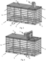
- FIG. 1 a collection device 1 for waste with a chute 2 and an accessible cover or platform 3 is shown.
- the collecting device 1 also has a lower support frame 4 made of steel and an upper support frame 5 made of steel.
- the two support frames 4 and 5 are connected to one another by means of corner supports 6.
- ribbed side walls 7 and 8 made of sheet steel are provided on the outside between the support frames 4 and 5.
- the bottom 9 of the lower support frame 4 is provided with cross bars 10, which are designed as I-beam beams (see Figure 3 ).
- the two support frames 4 and 5, the corner supports, the ribbed side walls 7 and 8 and the floor 9 essentially form a standardized freight container 11, but without a lid, ie the lid is formed by the walk-on cover or platform 3.
- FIGs 3 and 4 correspond to the Figures 1 and 2 , here in a transparent representation, with a lifting device 12 visible. Details are provided below in connection with the Figures 7 and 8th clarified.
- the collecting device 1 with a press container 13 is shown in a transparent representation.
- Figure 6 shows the lifting device 12 with the press container 13 placed on it and the accessible cover 3 of the collecting device 1.
- Such a press container 13 is known, for example, from the company Pöttinger Disposal Technology GmbH, A-4710 Griesmün and in EP 2 103 422 B1 described.
- a rectangular passage 14 is provided below the insertion shaft 2, which fits the filling opening of the press container 13. In this passage 14 there is an electrical control - not visible here - for folding down the chute 2 and operating the lifting device 12 and the required hydraulics.
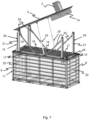
- the collecting device 1 is shown in the open state with the lifting device 12 raised in the freight container 11, which has a support frame 15 made of steel with rectangular gratings 16.
- the gratings 16 are intended to prevent an operator from falling into the open freight container 11.
- the longitudinal beams 17 of the support frame 15 also serve as rails for the - in Figure 6 not visible - rollers of the press container 13.
- stop elements 18 are provided for the press container 13 so that the press container 13 can be correctly positioned with respect to the insertion shaft 2 and the platform 3.
- Parallel to the corner supports 6 and slightly offset inwards Four lifting cylinders 20 with a cylinder part 21 and a piston part 22 are provided on the support frame 15, with which the lifting device 12 can be raised.
- cross struts 24 are fastened between the cylinder parts 21 and the longitudinal beams 17 of the support frame 15 in order to give the lifting cylinders 20 the necessary stability.
- the cross struts 24 are attached at an angle of approximately 45 ° to the longitudinal beam 17.
- two lifting cylinders 25 are provided, which are located on the same fastening 26 of the cross struts 24 shown on the left in the figure are located.
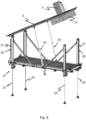
- Figure 8 shows the lifting device 12 with the accessible cover or platform 3 without the open freight container 11.
- ISO containers are standardized large-capacity containers (sea freight containers) made of steel that enable simple and quick loading, transport, storage and unloading of goods.
- the relevant standards e.g. mass, brackets, stackability
- the most common ISO containers are 8 feet (2.4384 m) wide and either 20 feet (6.096 m) or 40 feet (12.192 m) long. This results in the abbreviations “TEU” (Twenty-foot Equivalent Unit) and “FEU” (Forty-foot Equivalent Unit) used as loading units; It is used, for example, to indicate the loading capacity of container ships, handling volumes in ports or freight stations.
- the containers are largely made of steel (usually the durable CORTEN steel).
- the production of a standard container takes place in several steps: First, the so-called “superstructure”, the basic structure of the container made of particularly stable steel parts, is assembled. At their corners are the cast steel container corners, also known in technical jargon as “corner castings” or simply “corners”. Struts are then drawn into the floor in the longitudinal direction.
- the container floor which consists of several layers of wood treated with protective agents, is mounted on these struts. Since the floor has to be very load-bearing and resilient, the plywood panels used are usually made from tropical hardwoods. Bamboo material is now also being used for container floors, with plants growing back ten times faster than tropical hardwood trees.
- the use of composite materials with recycled plastic is also being investigated, Wood Plastic Composite Floorboards for Maersk Container Industry (MCI).
- MCI Wood Plastic Composite Floorboards for Maersk Container Industry
- the walls of the container are made of trapezoidal sheet steel (Corrugation) or, more rarely, smooth sheet steel.
- the container roof and doors are then installed.
- the container is then given a protective coating and given its container number and manufacturer information.
- a toggle lever mechanism can also be provided.
Landscapes
- Engineering & Computer Science (AREA)
- Mechanical Engineering (AREA)
- Refuse Collection And Transfer (AREA)
- Processing Of Solid Wastes (AREA)
Description
- Die Erfindung betrifft eine unterirdische Sammeleinrichtung für Abfälle nach dem Oberbegriff des Patentanspruchs 1.
- Eine solche unterirdische Sammeleinrichung mit Untergrund-Containern ist allgemein bekannt. Diese weisen eine in vertikaler Richtung hebbaren Plattform auf, welche dazu dient, einen oder mehreren Abfallcontainer zu tragen. Ferner ist eine auf einem der Höhe der Abfallcontainer entsprechenden vertikalen Abstand von der Plattform angeordnete, begehbare Abdeckung mit Einwurfschacht vorgesehen.
- Beispielsweise ist in
EP 2 316 754 A1 eine unterirdische Sammeleinrichung beschrieben, die die Merkmale des Oberbegriffs des Anspruchs 1 aufweist, und zwar mit einem Träger, auf welchem ein Abfallcontainer abstellbar ist. Mit einer Hebvorrichtung mit Seilzügen und Rollen kann der Träger auf Erdniveau angehoben werden. Der Träger weist einen flachen rechteckigen Rahmen auf, an dessen Ecken je das eine Ende eines Seilzuges angebracht ist. Die Hebevorrichtung weist einen parallel zum Träger pneumatisch oder hydraulisch bewegbaren Schlitten auf, wobei das andere Ende eines jeden Seilzuges am Schlitten angebracht ist. - In
EP 1 312 566 A1 ist eine unterirdische Sammeleinrichtung beschrieben, welche in einer Grube untergebracht ist, welche eine Plattform aufweist, die geeignet ist für einen auf einem Lastwagen transportierbaren Abfallcontainer. Der Abfallcontainer weist eine begehbare Abdeckung mit Einwurfschacht auf. Mit einem Hydraulikzylinder, der mittig unter der Plattform angeordnet ist, kann die Sammeleinrichtung aus der Grube auf Erdniveau angehoben werden, um den Abfallcontainer auf einen Lastwagen aufzuladen. - Bei diesen bekannten unterirdischen Sammeleinrichtungen wird eine quaderförmige Grube erstellt, welche aus Beton besteht. Um eine solche Sammeleinrichtung betriebsbereit zu erstellen, sind daher Bau- und Montage-Arbeiten von mehreren Wochen notwendig.
- Es ist nun Aufgabe der vorliegenden Erfindung, eine unterirdische Sammeleinrichtung anzugeben, welche baldmöglichst nach dem Transport betriebsbereit ist.
- Diese Aufgabe wird durch eine unterirdische Sammeleinrichtung mit den Merkmalen des Patentanspruchs 1 gelöst.
- Die erfindungsgemässe unterirdische Sammeleinrichtung ist mit einer Hebevorrichtung und einer in vertikaler Richtung von der Hebevorrichtung hebbaren und begehbaren Plattform versehen.
- Die Hebevorrichtung dient dazu, einen oder mehreren Abfallcontainer zu tragen, wobei die Plattform einen Einwurfschacht aufweist. Die Sammeleinrichtung umfasst weiterhin einen Frachtgut-Container. Ferner ist die Hebevorrichtung in dem Frachgut-Container angeordnet, wobei die begehbare Plattform der Sammeleinrichtung gleichzeitig die Abdeckung des Frachtgut-Containers bildet.
- Die erfindungsgemässe Sammeleinrichtung hat den grossen Vorteil, dass lediglich mit einem Bagger eine Grube im Erdreich ausgehoben werden muss und die Sammeleinrichtung mit einem Kran in die Grube gestellt werden kann. Es entfällt somit die aufwendigen Bauarbeiten, um die Grube mit Beton oder Betonelementen auszukleiden.
- In einer bevorzugten Ausführung gemäss Anspruch 2 weist der Frachtgut-Container einen Boden mit Querstreben aus Stahl.
- Dabei kann die Hebevorrichtung einen rechteckigen Trägerrahmen und vier Hubzylinder aufweisen.
- In einer weiteren Ausführung gemäss Anspruch 3 weist der Trägerrahmen Längsträger auf, die als Schienen für die Rollen eines Presscontainers dienen.
- In einer Ausführung gemäss Anspruch 4 kann die Hebevorrichtung Gitterroste auf dem Trägerrahmen aufweisen.
- Die Hubzylinder können dabei gemäss Anspruch 5 einen Zylinderteil und einen Kolbenteil aufweisen.
- In einer bevorzugten Ausführung gemäss Anspruch 6 können Querstreben zwischen den Zylinderteilen und den Längträgern des Trägerrahmens befestigt sein.
- In einer weiteren Ausführung gemäss Anspruch 7 weist die Hebevorrichtung mindestens einen Hubzylinder auf, um die begehbare Abdeckung oder Plattform einseitig anzuheben oder zu kippen.
- Weitere Vorteile der Erfindung ergeben sich aus den abhängigen Patentansprüchen und aus der nachfolgenden Beschreibung, in welcher die Erfindung anhand eines in den schematischen Zeichnungen dargestellten Ausführungsbeispieles näher erläutert wird. Es zeigt:
- Fig. 1
- eine Sammeleinrichtung in einem Frachtgut-Container in geschlossenem Zustand mit Einfüllschacht, in perspektivischer Darstellung,
- Fig. 2
- die Sammeleinrichtung in geschlossenem Zustand mit abgekipptem Einfüllschacht, in perspektivischer Darstellung,
- Fig. 3
- die Sammeleinrichtung gemäss
Figur 1 in durchsichtiger und perspektivischer Darstellung, - Fig. 4
- die Sammeleinrichtung gemäss
Figur 2 in durchsichtiger und perspektivischer Darstellung, - Fig. 5
- die Sammeleinrichtung der
Figur 1 , wobei ein Presscontainer ersichtlich ist, - Fig. 6
- den Presscontainer auf der Hebevorrichtung mit der begehbaren Abdeckung der Sammeleinrichtung,
- Fig. 7
- die Sammeleinrichtung in durchsichtiger und perspektivischer Darstellung mit angehobener Hebevorrichtigung und angehobenen Abdeckung, und
- Fig. 8
- die Hebevorrichtung perspektivisch in Einzeldarstellung.
- In den Figuren sind für dieselben Elemente dieselben Bezugszeichen verwendet, wenn nichts anderes erwähnt worden ist.
- In
Figur 1 ist eine Sammeleinrichtung 1 für Abfälle mit einem Einwurfschacht 2 und einer begehbaren Abdeckung oder Plattform 3 gezeigt. Die Sammeleinrichtung 1 weist ferner einen unteren Trägerrahmen 4 aus Stahl und einen oberen Trägerrahmen 5 aus Stahl auf. Die beiden Trägerrahmen 4 und 5 sind mittels Eckstützen 6 miteinander verbunden. Ferner sind gerippte Seitenwände 7 und 8 aus Stahlblech aussen zwischen den Trägerrahmen 4 und 5 vorgesehen. Der Boden 9 des unteren Trägerrahmens 4 ist mit Querstäben 10 versehen, welche als I-Trägerbalken ausgebildet sind (sieheFigur 3 ). Die beiden Trägerrahmen 4 und 5, die Eckstützen, die gerippten Seitenwänden 7 und 8 und der Boden 9 bilden im Wesentlichen eine genormte Frachtgut-Container 11, jedoch ohne Deckel, d.h. der Deckel wird von der begehbaren Abdeckung oder Plattform 3 gebildet. - In
Figur 2 ist die Sammeleinrichtung 1 mit abgeklapptem Einwurfschacht 2 ersichtlich. - Die
Figuren 3 und 4 entsprechen denFiguren 1 und 2 , hier in einer durchsichtigen Darstellung, wobei eine Hebevorrichtung 12 ersichtlich ist. Einzelheiten werden unten in Zusammenhang mit denFiguren 7 und8 verdeutlicht. InFigur 5 ist die Sammeleinrichtung 1 mit einem Presscontainer 13 in durchsichtiger Darstellung gezeigt.Figur 6 zeigt die Hebevorrichtung 12 mit dem darauf gestellten Presscontainer 13 und die begehbare Abdeckung 3 der Sammeleinrichtung 1. Ein solcher Presscontainer 13 ist beispielsweise bekannt von der Firma Pöttinger Entsorgungstechnik GmbH, A-4710 Grieskirchen und inEP 2 103 422 B1 beschrieben. Unterhalb des Einwurfschachts 2 ist ein rechteckiger Durchgang 14 vorgesehen, welcher passend zur Befüllöffnung des Presscontainers 13 ist. In diesem Durchgang 14 ist eine - hier nicht ersichtliche - elektrische Steuerung für das Abklappen des Einwurfschachts 2 und die Bedienung der Hebevorrichtung 12 und die erforderliche Hydraulik vorgesehen. - In
Figur 7 ist die Sammeleinrichtung 1 in geöffnetem Zustand mit angehobener Hebevorrichtung 12 im Frachtgut-Container 11 dargestellt, welche einen Trägerrahmen 15 aus Stahl mit rechteckigen Gitterrosten 16 aufweist. Die Gitterroste 16 sollen verhindern, dass eine Bedienungsperson in den offenen Frachtgut-Container 11 fallen kann. Die Längsträger 17 des Trägerrahmens 15 dienen gleichzeitig als Schienen für die - inFigur 6 nicht ersichtlichen - Rollen des Presscontainers 13. An den Enden dieser Längsträger 17 sind Stoppelemente 18 für den Presscontainer 13 vorgesehen, damit der Presscontainer 13 richtig positioniert werden kann bezüglich des Einwurfschachts 2 und der Plattform 3. Parallel zu den Eckstützen 6 und etwas nach innen versetzt sind am Trägerrahmen 15 vier Hubzylinder 20 mit einem Zylinderteil 21 und einem Kolbenteil 22 vorgesehen, mit welchen die Hebevorrichtung 12 angehoben werden kann. Ferner sind Querstreben 24 zwischen den Zylinderteilen 21 und den Längsträgern 17 des Trägerrahmens 15 befestigt, um die Hubzylinder 20 die nötige Stabilität zu geben. Die Querstreben 24 sind in einem Winkel von etwa 45° zum Längsträger 17 befestigt. Um die begehbare Abdeckung oder Plattform 3 anzuheben, sind zwei Hubzylinder 25 vorgesehen, welche sich auf derselben Befestigung 26 der in der Figur links ersichtlichen Querstreben 24 befinden. -
Figur 8 zeigt die Hebevorrichtung 12 mit der begehbaren Abdeckung oder Plattform 3 ohne den offenen Frachtgut-Container 11. - ISO-Container sind genormte Grossraumbehälter (Seefracht-Container, engl. Freight containers) aus Stahl, die ein einfaches und schnelles Verladen, Befördern, Lagern und Entladen von Gütern ermöglichen. Die einschlägigen Normen (z. B. Masse, Halterungen, Stapelbarkeit) wurden koordiniert von der Internationalen Seeschifffahrts-Organisation (IMO) beschlossen und sind in der ISO-Norm 668 festgelegt. Die am weitesten verbreiteten ISO-Container haben eine Breite von 8 Fuss (2,4384 m) und sind entweder 20 Fuss (6,096 m) oder 40 Fuß (12,192 m) lang. Daraus ergeben sich die als Beladungs-Masseinheiten verwendete Abkürzungen "TEU" (Twenty-foot Equivalent Unit) und "FEU" (Forty-foot Equivalent Unit); es wird beispielsweise zur Benennung der Ladefähigkeit von Containerschiffen, von Umschlagsmengen in Häfen oder von Güterbahnhöfen verwendet. Die Container bestehen zum Grossteil aus Stahl (meist dem widerstandsfähigen CORTENStahl). Die Herstellung eines Standardcontainers erfolgt in mehreren Schritten: Zuerst wird die so genannte "superstructure", das Grundgerüst des Containers aus besonders stabilen Stahlteilen, montiert. An deren Ecken befinden sich die Stahlguss-Containerecken, im Fachjargon auch "corner-castings" oder schlicht "corners" genannt. Anschliessend werden am Boden in Längsrichtung Streben eingezogen. Auf diesen Streben wird der Containerboden montiert, der aus mehreren Lagen von mit Schutzmitteln behandeltem Holz besteht. Da der Boden sehr tragfähig und widerstandsfähig sein muss, bestehen die verwendeten Sperrholzplatten meist aus tropischen Harthölzern. Inzwischen wird auch Material aus Bambus für die Containerböden benutzt, deren Pflanzen zehnmal schneller nachwachsen als tropische Hartholzbäume. Auch die Benutzung von Kompositwerkstoffen mit recyceltem Kunststoff werden untersucht, Wood Plastic Composit Floorboards für Maersk Container Industry (MCI). Die Wände des Containers bestehen aus Trapez-Stahlblech (Corrugation) oder seltener glattem Stahlblech. Anschliessend werden das Containerdach und die Türen montiert. Danach wird der Container mit einer schützenden Lackierung versehen und erhält seine Containernummer und die Herstellerangaben.
- Es versteht sich, dass anstelle von zwei Hubzylindern 25 auch eine einzelne Hubzylinder vorgesehen sein kann, welche sich etwa mittig auf dem Trägerrahmen 15 abstützt.
- Anstelle von Hubzylinder 25 kann auch ein Kniehebel-Mechanismus vorgesehen sein.
- Anstelle eines einzigen Presscontainers 13 können auch mehrere Abfallcontainer auf dem Trägerrahmen 15 abgestellt werden, wobei dann mehrere Einwurfschächte 2 für die jeweiligen Abfallcontainer vorgesehen sind.
Claims (7)
- Unterirdische Sammeleinrichtung (1) für Abfälle, umfassend eine Hebevorrichtung und eine in vertikaler Richtung von der Hebevorrichtung (12) hebbaren und begehbaren Plattform (3), welche Hebevorrichtung (12) dazu dient, einen oder mehreren Abfallcontainer zu tragen, wobei die Plattform (3) einen Einwurfschacht (2) aufweist, und die Hebevorrichtung (12) einen rechteckigen Trägerrahmen (15) mit Eckstützen und vier parallel zu den Eckstützen angeordnete Hubzylinder (20) aufweist, dadurch gekennzeichnet, dass die Sammeleinrichtung (1) weiter einen Frachtgut-Container (11) umfasst, und dass die Hebevorrichtung der Sammeleinrichtung (1) in dem Frachgut-Container (11) angeordnet ist, wobei die begehbare Plattform (3) der Sammeleinrichtung gleichzeitig die Abdeckung des Frachtgut-Containers (11) bildet.
- Unterirdische Sammeleinrichung (1) nach Anspruch 1, dadurch gekennzeichnet, dass der Frachtgut-Container (11) einen Boden (9) mit Querstreben (10) aus Stahl aufweist.
- Unterirdische Sammeleinrichtung (1) nach Anspruch 2, dadurch gekennzeichnet, dass der Trägerrahmen (15) Längsträger (17) aufweist, die als Schienen für die Rollen eines Presscontainers (13) dienen.
- Unterirdische Sammeleinrichtung (1) nach Anspruch 2 oder 3, dadurch gekennzeichnet, dass die Hebevorrichtung (12) Gitterroste (16) auf dem Trägerrahmen (15) aufweist.
- Unterirdische Sammeleinrichtung (1) nach einem der Ansprüche 1 bis 4, dadurch gekennzeichnet, dass die Hubzylinder (20) einen Zylinderteil (21) und einen Kolbenteil (22) aufweisen.
- Unterirdische Sammeleinrichung (1) nach Anspruch 5, dadurch gekennzeichnet, dass Querstreben (24) zwischen den Zylinderteilen (21) und den Längträgern (17) des Trägerrahmens (15) befestigt sind.
- Unterirdische Sammeleinrichtung (1) nach einem der Ansprüche 1 bis 6, dadurch gekennzeichnet, dass die Hebevorrichtung (12) mindestens einen weiteren Hubzylinder (25) aufweist, um die begehbare Abdeckung oder Plattform (3) einseitig anzuheben oder zu kippen.
Applications Claiming Priority (2)
| Application Number | Priority Date | Filing Date | Title |
|---|---|---|---|
| CH12562017 | 2017-10-14 | ||
| PCT/IB2018/057979 WO2019073462A1 (de) | 2017-10-14 | 2018-10-15 | Unterirdische sammeleinrichtung für abfälle |
Publications (2)
| Publication Number | Publication Date |
|---|---|
| EP3694792A1 EP3694792A1 (de) | 2020-08-19 |
| EP3694792B1 true EP3694792B1 (de) | 2023-11-22 |
Family
ID=64109959
Family Applications (1)
| Application Number | Title | Priority Date | Filing Date |
|---|---|---|---|
| EP18797131.2A Active EP3694792B1 (de) | 2017-10-14 | 2018-10-15 | Unterirdische sammeleinrichtung für abfälle |
Country Status (4)
| Country | Link |
|---|---|
| EP (1) | EP3694792B1 (de) |
| CN (1) | CN111212796A (de) |
| ES (1) | ES2968521T3 (de) |
| WO (1) | WO2019073462A1 (de) |
Family Cites Families (11)
| Publication number | Priority date | Publication date | Assignee | Title |
|---|---|---|---|---|
| DE19758570C2 (de) * | 1997-05-21 | 2002-10-31 | Roland Kohler | Bodenbehälter |
| CN2373411Y (zh) * | 1999-05-25 | 2000-04-12 | 张书勤 | 地平式垃圾集装箱 |
| ES2173797B1 (es) * | 2000-06-23 | 2004-03-01 | Habas Angel Antoli | Cajon soterrado con elevador para contenedores de basura. |
| ITMN20010043A1 (it) | 2001-10-25 | 2003-04-25 | Carlo Galeazzi | Dispositivo per la raccolta di rifiuti |
| CN2571706Y (zh) * | 2002-09-25 | 2003-09-10 | 秦安军 | 液压升降式可移运地下垃圾箱 |
| DE202008003794U1 (de) | 2008-03-18 | 2009-08-13 | Pöttinger Entsorgungstechnik GmbH & Co. KG | Pressvorrichtung für Abfälle und Wertstoffe |
| CH702074A2 (de) | 2009-10-27 | 2011-04-29 | Villiger Entsorgungssysteme Ag | Unterirdische Sammeleinrichtung für Abfälle. |
| ES1072315Y (es) * | 2010-04-13 | 2010-09-17 | Martinez Daniel Canovas | Dispositivo soterrado con plataforma elevadora de contenedores para residuos urbanos |
| CN202440036U (zh) * | 2012-02-15 | 2012-09-19 | 曲建亭 | 一种地埋式环保垃圾箱 |
| CN203845278U (zh) * | 2014-04-13 | 2014-09-24 | 昌吉市三吉隆环卫设备有限责任公司 | 多液压缸举升式地埋垃圾箱 |
| CN205327927U (zh) * | 2016-02-05 | 2016-06-22 | 克拉玛依市诚谊科技服务有限公司 | 导向机构中置式双桶垃圾箱 |
-
2018
- 2018-10-15 WO PCT/IB2018/057979 patent/WO2019073462A1/de not_active Ceased
- 2018-10-15 CN CN201880067041.9A patent/CN111212796A/zh active Pending
- 2018-10-15 EP EP18797131.2A patent/EP3694792B1/de active Active
- 2018-10-15 ES ES18797131T patent/ES2968521T3/es active Active
Non-Patent Citations (1)
| Title |
|---|
| ANONYMOUS: "Intermodal container - Wikipedia", 28 September 2017 (2017-09-28), XP055804214, Retrieved from the Internet <URL:https://en.wikipedia.org/w/index.php?title=Intermodal_container&oldid=802803604> [retrieved on 20210512] * |
Also Published As
| Publication number | Publication date |
|---|---|
| WO2019073462A1 (de) | 2019-04-18 |
| CN111212796A (zh) | 2020-05-29 |
| ES2968521T3 (es) | 2024-05-10 |
| EP3694792A1 (de) | 2020-08-19 |
Similar Documents
| Publication | Publication Date | Title |
|---|---|---|
| DE1937205A1 (de) | Transportgestell oder Fahrzeugladeflaeche fuer Kabelrollen od.dgl. | |
| EP2361739B1 (de) | Anlage zur Herstellung von Betonfertigteilen | |
| DE60005852T2 (de) | Verfahren und vorrichtung zum seetransport von wickelrollen, zwischendeck und zwischendeckanordnung im ladebereich von schiffen | |
| DE3430642C2 (de) | Verfahrbarer Schrägaufzug | |
| EP0444334B1 (de) | Mobiler Rottebehälter | |
| EP3694792B1 (de) | Unterirdische sammeleinrichtung für abfälle | |
| EP2546162B1 (de) | Palette zum Transport von Rund- oder Schnittholz | |
| DE202010010891U1 (de) | Transportpalette | |
| DE2317695A1 (de) | Heb- und senkbare plattform fuer einen kraftwagen, insbesondere als zugang einer unterflurgarage | |
| DE19740814A1 (de) | Containerbrückensystem | |
| AT17104U1 (de) | ISO-Normcontainer | |
| EP0206094B1 (de) | Saugheber | |
| DE69919417T2 (de) | Schiffbau-Verfahren | |
| DE2159602A1 (de) | Verfahren zum transportieren von grossraumbehaeltern wie tanks, silos u. dgl | |
| DE202010009455U1 (de) | Transportbehälter mit oberer Abdeckung | |
| DE3143930C2 (de) | ||
| EP0581209B1 (de) | Schiffskran in Verbindung mit einem Schiff, insbesondere Kühlschiff | |
| EP0870720B1 (de) | Vorrichtung zum Transportieren eines Aufzugssystems | |
| DE548306C (de) | Foerdergeruest fuer Schachtgefaessfoerderung | |
| DE10245438B4 (de) | Verfahren zum Abtransport einer Schwerlast, insbesondere eines aktivierte Primärkreiskomponenten enthaltenden Behälters, aus dem Reaktorgebäude eines Kernkraftwerkes | |
| DE29707713U1 (de) | Transportpalette für plattenartiges Schwergut | |
| DE202008008416U1 (de) | Vorrichtung zum Hochkippen eines Containers | |
| DD205864A1 (de) | Lastaufnahmemittel fuer den vertikal- und horizontaltransport von plattenfoermigem baumaterial | |
| DE4233726A1 (de) | Verfahren zum Be- und Entladen von Materialien in und aus umschlossenen Räumen sowie Einrichtung zur Abdeckung oder Luken von umschlossenen Räumen | |
| DE2229276A1 (de) | Normcontainer |
Legal Events
| Date | Code | Title | Description |
|---|---|---|---|
| STAA | Information on the status of an ep patent application or granted ep patent |
Free format text: STATUS: UNKNOWN |
|
| STAA | Information on the status of an ep patent application or granted ep patent |
Free format text: STATUS: THE INTERNATIONAL PUBLICATION HAS BEEN MADE |
|
| PUAI | Public reference made under article 153(3) epc to a published international application that has entered the european phase |
Free format text: ORIGINAL CODE: 0009012 |
|
| STAA | Information on the status of an ep patent application or granted ep patent |
Free format text: STATUS: REQUEST FOR EXAMINATION WAS MADE |
|
| 17P | Request for examination filed |
Effective date: 20200511 |
|
| AK | Designated contracting states |
Kind code of ref document: A1 Designated state(s): AL AT BE BG CH CY CZ DE DK EE ES FI FR GB GR HR HU IE IS IT LI LT LU LV MC MK MT NL NO PL PT RO RS SE SI SK SM TR |
|
| AX | Request for extension of the european patent |
Extension state: BA ME |
|
| DAV | Request for validation of the european patent (deleted) | ||
| DAX | Request for extension of the european patent (deleted) | ||
| STAA | Information on the status of an ep patent application or granted ep patent |
Free format text: STATUS: EXAMINATION IS IN PROGRESS |
|
| 17Q | First examination report despatched |
Effective date: 20210520 |
|
| GRAP | Despatch of communication of intention to grant a patent |
Free format text: ORIGINAL CODE: EPIDOSNIGR1 |
|
| STAA | Information on the status of an ep patent application or granted ep patent |
Free format text: STATUS: GRANT OF PATENT IS INTENDED |
|
| INTG | Intention to grant announced |
Effective date: 20230601 |
|
| GRAS | Grant fee paid |
Free format text: ORIGINAL CODE: EPIDOSNIGR3 |
|
| GRAA | (expected) grant |
Free format text: ORIGINAL CODE: 0009210 |
|
| STAA | Information on the status of an ep patent application or granted ep patent |
Free format text: STATUS: THE PATENT HAS BEEN GRANTED |
|
| AK | Designated contracting states |
Kind code of ref document: B1 Designated state(s): AL AT BE BG CH CY CZ DE DK EE ES FI FR GB GR HR HU IE IS IT LI LT LU LV MC MK MT NL NO PL PT RO RS SE SI SK SM TR |
|
| REG | Reference to a national code |
Ref country code: GB Ref legal event code: FG4D Free format text: NOT ENGLISH |
|
| REG | Reference to a national code |
Ref country code: CH Ref legal event code: EP |
|
| REG | Reference to a national code |
Ref country code: DE Ref legal event code: R096 Ref document number: 502018013688 Country of ref document: DE |
|
| REG | Reference to a national code |
Ref country code: IE Ref legal event code: FG4D Free format text: LANGUAGE OF EP DOCUMENT: GERMAN |
|
| REG | Reference to a national code |
Ref country code: LT Ref legal event code: MG9D |
|
| REG | Reference to a national code |
Ref country code: NL Ref legal event code: MP Effective date: 20231122 |
|
| PG25 | Lapsed in a contracting state [announced via postgrant information from national office to epo] |
Ref country code: GR Free format text: LAPSE BECAUSE OF FAILURE TO SUBMIT A TRANSLATION OF THE DESCRIPTION OR TO PAY THE FEE WITHIN THE PRESCRIBED TIME-LIMIT Effective date: 20240223 |
|
| PG25 | Lapsed in a contracting state [announced via postgrant information from national office to epo] |
Ref country code: IS Free format text: LAPSE BECAUSE OF FAILURE TO SUBMIT A TRANSLATION OF THE DESCRIPTION OR TO PAY THE FEE WITHIN THE PRESCRIBED TIME-LIMIT Effective date: 20240322 |
|
| PG25 | Lapsed in a contracting state [announced via postgrant information from national office to epo] |
Ref country code: LT Free format text: LAPSE BECAUSE OF FAILURE TO SUBMIT A TRANSLATION OF THE DESCRIPTION OR TO PAY THE FEE WITHIN THE PRESCRIBED TIME-LIMIT Effective date: 20231122 |
|
| PG25 | Lapsed in a contracting state [announced via postgrant information from national office to epo] |
Ref country code: NL Free format text: LAPSE BECAUSE OF FAILURE TO SUBMIT A TRANSLATION OF THE DESCRIPTION OR TO PAY THE FEE WITHIN THE PRESCRIBED TIME-LIMIT Effective date: 20231122 |
|
| PG25 | Lapsed in a contracting state [announced via postgrant information from national office to epo] |
Ref country code: NL Free format text: LAPSE BECAUSE OF FAILURE TO SUBMIT A TRANSLATION OF THE DESCRIPTION OR TO PAY THE FEE WITHIN THE PRESCRIBED TIME-LIMIT Effective date: 20231122 Ref country code: LT Free format text: LAPSE BECAUSE OF FAILURE TO SUBMIT A TRANSLATION OF THE DESCRIPTION OR TO PAY THE FEE WITHIN THE PRESCRIBED TIME-LIMIT Effective date: 20231122 Ref country code: IS Free format text: LAPSE BECAUSE OF FAILURE TO SUBMIT A TRANSLATION OF THE DESCRIPTION OR TO PAY THE FEE WITHIN THE PRESCRIBED TIME-LIMIT Effective date: 20240322 Ref country code: GR Free format text: LAPSE BECAUSE OF FAILURE TO SUBMIT A TRANSLATION OF THE DESCRIPTION OR TO PAY THE FEE WITHIN THE PRESCRIBED TIME-LIMIT Effective date: 20240223 Ref country code: BG Free format text: LAPSE BECAUSE OF FAILURE TO SUBMIT A TRANSLATION OF THE DESCRIPTION OR TO PAY THE FEE WITHIN THE PRESCRIBED TIME-LIMIT Effective date: 20240222 Ref country code: PT Free format text: LAPSE BECAUSE OF FAILURE TO SUBMIT A TRANSLATION OF THE DESCRIPTION OR TO PAY THE FEE WITHIN THE PRESCRIBED TIME-LIMIT Effective date: 20240322 |
|
| REG | Reference to a national code |
Ref country code: ES Ref legal event code: FG2A Ref document number: 2968521 Country of ref document: ES Kind code of ref document: T3 Effective date: 20240510 |
|
| PG25 | Lapsed in a contracting state [announced via postgrant information from national office to epo] |
Ref country code: SE Free format text: LAPSE BECAUSE OF FAILURE TO SUBMIT A TRANSLATION OF THE DESCRIPTION OR TO PAY THE FEE WITHIN THE PRESCRIBED TIME-LIMIT Effective date: 20231122 Ref country code: RS Free format text: LAPSE BECAUSE OF FAILURE TO SUBMIT A TRANSLATION OF THE DESCRIPTION OR TO PAY THE FEE WITHIN THE PRESCRIBED TIME-LIMIT Effective date: 20231122 Ref country code: PL Free format text: LAPSE BECAUSE OF FAILURE TO SUBMIT A TRANSLATION OF THE DESCRIPTION OR TO PAY THE FEE WITHIN THE PRESCRIBED TIME-LIMIT Effective date: 20231122 Ref country code: NO Free format text: LAPSE BECAUSE OF FAILURE TO SUBMIT A TRANSLATION OF THE DESCRIPTION OR TO PAY THE FEE WITHIN THE PRESCRIBED TIME-LIMIT Effective date: 20240222 Ref country code: LV Free format text: LAPSE BECAUSE OF FAILURE TO SUBMIT A TRANSLATION OF THE DESCRIPTION OR TO PAY THE FEE WITHIN THE PRESCRIBED TIME-LIMIT Effective date: 20231122 Ref country code: HR Free format text: LAPSE BECAUSE OF FAILURE TO SUBMIT A TRANSLATION OF THE DESCRIPTION OR TO PAY THE FEE WITHIN THE PRESCRIBED TIME-LIMIT Effective date: 20231122 |
|
| PG25 | Lapsed in a contracting state [announced via postgrant information from national office to epo] |
Ref country code: DK Free format text: LAPSE BECAUSE OF FAILURE TO SUBMIT A TRANSLATION OF THE DESCRIPTION OR TO PAY THE FEE WITHIN THE PRESCRIBED TIME-LIMIT Effective date: 20231122 |
|
| PG25 | Lapsed in a contracting state [announced via postgrant information from national office to epo] |
Ref country code: CZ Free format text: LAPSE BECAUSE OF FAILURE TO SUBMIT A TRANSLATION OF THE DESCRIPTION OR TO PAY THE FEE WITHIN THE PRESCRIBED TIME-LIMIT Effective date: 20231122 |
|
| PG25 | Lapsed in a contracting state [announced via postgrant information from national office to epo] |
Ref country code: SK Free format text: LAPSE BECAUSE OF FAILURE TO SUBMIT A TRANSLATION OF THE DESCRIPTION OR TO PAY THE FEE WITHIN THE PRESCRIBED TIME-LIMIT Effective date: 20231122 |
|
| PG25 | Lapsed in a contracting state [announced via postgrant information from national office to epo] |
Ref country code: SM Free format text: LAPSE BECAUSE OF FAILURE TO SUBMIT A TRANSLATION OF THE DESCRIPTION OR TO PAY THE FEE WITHIN THE PRESCRIBED TIME-LIMIT Effective date: 20231122 Ref country code: SK Free format text: LAPSE BECAUSE OF FAILURE TO SUBMIT A TRANSLATION OF THE DESCRIPTION OR TO PAY THE FEE WITHIN THE PRESCRIBED TIME-LIMIT Effective date: 20231122 Ref country code: RO Free format text: LAPSE BECAUSE OF FAILURE TO SUBMIT A TRANSLATION OF THE DESCRIPTION OR TO PAY THE FEE WITHIN THE PRESCRIBED TIME-LIMIT Effective date: 20231122 Ref country code: EE Free format text: LAPSE BECAUSE OF FAILURE TO SUBMIT A TRANSLATION OF THE DESCRIPTION OR TO PAY THE FEE WITHIN THE PRESCRIBED TIME-LIMIT Effective date: 20231122 Ref country code: DK Free format text: LAPSE BECAUSE OF FAILURE TO SUBMIT A TRANSLATION OF THE DESCRIPTION OR TO PAY THE FEE WITHIN THE PRESCRIBED TIME-LIMIT Effective date: 20231122 Ref country code: CZ Free format text: LAPSE BECAUSE OF FAILURE TO SUBMIT A TRANSLATION OF THE DESCRIPTION OR TO PAY THE FEE WITHIN THE PRESCRIBED TIME-LIMIT Effective date: 20231122 |
|
| REG | Reference to a national code |
Ref country code: DE Ref legal event code: R097 Ref document number: 502018013688 Country of ref document: DE |
|
| PLBE | No opposition filed within time limit |
Free format text: ORIGINAL CODE: 0009261 |
|
| STAA | Information on the status of an ep patent application or granted ep patent |
Free format text: STATUS: NO OPPOSITION FILED WITHIN TIME LIMIT |
|
| PG25 | Lapsed in a contracting state [announced via postgrant information from national office to epo] |
Ref country code: SI Free format text: LAPSE BECAUSE OF FAILURE TO SUBMIT A TRANSLATION OF THE DESCRIPTION OR TO PAY THE FEE WITHIN THE PRESCRIBED TIME-LIMIT Effective date: 20231122 |
|
| 26N | No opposition filed |
Effective date: 20240823 |
|
| PG25 | Lapsed in a contracting state [announced via postgrant information from national office to epo] |
Ref country code: SI Free format text: LAPSE BECAUSE OF FAILURE TO SUBMIT A TRANSLATION OF THE DESCRIPTION OR TO PAY THE FEE WITHIN THE PRESCRIBED TIME-LIMIT Effective date: 20231122 |
|
| GBPC | Gb: european patent ceased through non-payment of renewal fee |
Effective date: 20241015 |
|
| PG25 | Lapsed in a contracting state [announced via postgrant information from national office to epo] |
Ref country code: MC Free format text: LAPSE BECAUSE OF FAILURE TO SUBMIT A TRANSLATION OF THE DESCRIPTION OR TO PAY THE FEE WITHIN THE PRESCRIBED TIME-LIMIT Effective date: 20231122 |
|
| PG25 | Lapsed in a contracting state [announced via postgrant information from national office to epo] |
Ref country code: GB Free format text: LAPSE BECAUSE OF NON-PAYMENT OF DUE FEES Effective date: 20241015 |
|
| PG25 | Lapsed in a contracting state [announced via postgrant information from national office to epo] |
Ref country code: BE Free format text: LAPSE BECAUSE OF NON-PAYMENT OF DUE FEES Effective date: 20241031 Ref country code: LU Free format text: LAPSE BECAUSE OF NON-PAYMENT OF DUE FEES Effective date: 20241015 |
|
| REG | Reference to a national code |
Ref country code: BE Ref legal event code: MM Effective date: 20241031 |
|
| PG25 | Lapsed in a contracting state [announced via postgrant information from national office to epo] |
Ref country code: FI Free format text: LAPSE BECAUSE OF FAILURE TO SUBMIT A TRANSLATION OF THE DESCRIPTION OR TO PAY THE FEE WITHIN THE PRESCRIBED TIME-LIMIT Effective date: 20231122 |
|
| PG25 | Lapsed in a contracting state [announced via postgrant information from national office to epo] |
Ref country code: IE Free format text: LAPSE BECAUSE OF NON-PAYMENT OF DUE FEES Effective date: 20241015 |
|
| REG | Reference to a national code |
Ref country code: CH Ref legal event code: U11 Free format text: ST27 STATUS EVENT CODE: U-0-0-U10-U11 (AS PROVIDED BY THE NATIONAL OFFICE) Effective date: 20251101 |
|
| PGFP | Annual fee paid to national office [announced via postgrant information from national office to epo] |
Ref country code: DE Payment date: 20251020 Year of fee payment: 8 |
|
| PGFP | Annual fee paid to national office [announced via postgrant information from national office to epo] |
Ref country code: AT Payment date: 20251021 Year of fee payment: 8 |
|
| PGFP | Annual fee paid to national office [announced via postgrant information from national office to epo] |
Ref country code: IT Payment date: 20251031 Year of fee payment: 8 |
|
| PGFP | Annual fee paid to national office [announced via postgrant information from national office to epo] |
Ref country code: FR Payment date: 20251024 Year of fee payment: 8 |
|
| PGFP | Annual fee paid to national office [announced via postgrant information from national office to epo] |
Ref country code: CH Payment date: 20251101 Year of fee payment: 8 |
|
| PG25 | Lapsed in a contracting state [announced via postgrant information from national office to epo] |
Ref country code: CY Free format text: LAPSE BECAUSE OF FAILURE TO SUBMIT A TRANSLATION OF THE DESCRIPTION OR TO PAY THE FEE WITHIN THE PRESCRIBED TIME-LIMIT; INVALID AB INITIO Effective date: 20181015 |
|
| PGFP | Annual fee paid to national office [announced via postgrant information from national office to epo] |
Ref country code: ES Payment date: 20251114 Year of fee payment: 8 |
|
| PG25 | Lapsed in a contracting state [announced via postgrant information from national office to epo] |
Ref country code: HU Free format text: LAPSE BECAUSE OF FAILURE TO SUBMIT A TRANSLATION OF THE DESCRIPTION OR TO PAY THE FEE WITHIN THE PRESCRIBED TIME-LIMIT; INVALID AB INITIO Effective date: 20181015 |