EP2316754A1 - Unterirdische Sammeleinrichtung für Abfälle - Google Patents
Unterirdische Sammeleinrichtung für Abfälle Download PDFInfo
- Publication number
- EP2316754A1 EP2316754A1 EP10189099A EP10189099A EP2316754A1 EP 2316754 A1 EP2316754 A1 EP 2316754A1 EP 10189099 A EP10189099 A EP 10189099A EP 10189099 A EP10189099 A EP 10189099A EP 2316754 A1 EP2316754 A1 EP 2316754A1
- Authority
- EP
- European Patent Office
- Prior art keywords
- carriage
- carrier
- collecting device
- cable
- lifting device
- Prior art date
- Legal status (The legal status is an assumption and is not a legal conclusion. Google has not performed a legal analysis and makes no representation as to the accuracy of the status listed.)
- Granted
Links
Images


Classifications
-
- B—PERFORMING OPERATIONS; TRANSPORTING
- B65—CONVEYING; PACKING; STORING; HANDLING THIN OR FILAMENTARY MATERIAL
- B65F—GATHERING OR REMOVAL OF DOMESTIC OR LIKE REFUSE
- B65F1/00—Refuse receptacles; Accessories therefor
- B65F1/14—Other constructional features; Accessories
- B65F1/1452—Lifting, hoisting, elevating mechanisms or the like for refuse receptacles
- B65F1/1457—Lifting, hoisting, elevating mechanisms or the like for refuse receptacles for refuse receptacles located underground
Definitions
- the invention relates to an underground collecting device for waste according to the preamble of patent claim 1.
- Such an underground collection facility with underground containers is well known.
- This has a support on which a waste container is turned off, a lifting device to raise the carrier to earth level, and a cover plate with chute on.
- a collecting device with a recessed in the ground housing with several sections for the accommodation of large containers is known.
- Each section consists of a platform with a cover and a hydraulic cylinder, which can move the container up and down via a cable guide with rollers.
- a carriage In a frame of the housing runs a carriage with four track rollers.
- the track rollers of the platform In the rails of the carriage, the track rollers of the platform are guided.
- the double rails result in a telescopic system, with which the platform can be lifted to ground level.
- the hydraulic cylinder engages two ropes via two rollers.
- the ropes are each attached at one end to a cross member of the carriage and at the other end via Umlenkseilrollen to the platform.
- the carriage When expanding the hydraulic cylinder, the carriage is first moved up to the stop. Afterwards, the platform moves at double the speed of the hydraulic cylinder to the earth level.
- the lifting device described in the above document is mechanically complex and takes a lot of space because of the various pulleys and the vertical hydraulic cylinder. Further, the slide and the platform are only guided on one side by means of track rollers in rails, so that jamming is not excluded because of one-sided load.
- the present invention is based on the object to improve an underground collecting device of the aforementioned type such that a uniform and balanced lifting of a waste container is made possible with a space-saving lifting device.
- the collecting device has the great advantage that the cover plate is lifted automatically even with uneven load on cables and pulleys by means of a carriage with the right force at all four corners. As a result, jamming of the cover plate when lifting is not possible.
- the mechanical structure of the collecting device with the pulleys and the cables is very simple and robust, so that a long service life is given.
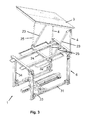
- a waste underground collection device 1 is shown in perspective, comprising a frame-shaped support 2, a cover plate 3 and four supporting posts 4.
- the posts 4 are arranged between the carrier 2 and the cover plate 3.
- the cover plate 3 has a circular opening 5, under which the insertion opening of a waste container can be placed in alignment.
- a lifting device 6 is provided with four, arranged parallel to the post 4 supports 7, which are connected in pairs with a ground-level support beam 8 together.
- a straight guide 9 is provided for a slide 10 which can be moved back and forth on the guide 9.
- This carriage 10 has two on the support beam 8 supporting cross member or arms 11. At the outer ends of the supports 7 are each a deflection roller 13 and 14 are attached.
- the arms 11 of the carriage 10 at their outer ends per two pulleys 16 and 17.
- the guide 9 has at one of its ends two pulleys 18 and 19.
- a hydraulic cylinder 20 is provided which reciprocates the carriage 10 on the guide 9.
- the carriage 10 can of course also be moved pneumatically by means of a pneumatic cylinder.
- Each cable 31 or 32 is guided over the pulleys 14, 13, 16, 30 and 18 (or 19) and each cable 33 or 34 is guided over the pulleys 14, 13, 17, 30 and 18 (or 19) to the carriage 10 ,
- the length of the cables are now such that the frame-shaped support 2 with its support legs 22 exactly horizontal, that is flush with the ends of the posts 7 when the collector is raised.
- the carrier 2 is lowered.
- the path which covers the carriage 10 from left to right corresponds exactly to the stroke of the carrier 2.
- FIG. 3 is now an extension of the collector 1 of FIGS. 1 and 2 represented here by the two - in the FIG. 2 omitted - left post 4 omitted and for two angle bracket 23 and an additional cross member 24 is provided on the frame-shaped carrier 2.
- the cover plate 3 is hinged at one end to the (remaining) post 4 and by means of two hydraulic cylinders 25th tiltable.
- a truck In order for a truck can be moved up with a loading bridge directly to the waste container and the container loaded by means of the loading bridge to the truck. Otherwise, one must first push the waste container out of the area of the collecting device 1 in order to charge it by means of the loading bridge on a truck, as in the execution of the FIGS. 1 and 2 the case is.
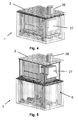
- FIGS. 4 and 5 the collecting device 1 in a perspective view with a waste container 27 and a mounted on the insertion opening 5 chute 28 in the retracted state ( Fig. 4 ) and in the raised state ( Fig. 5 ).
- a plurality of chutes 28 may be provided on the cover plate 3, so that a plurality of smaller waste containers can be lifted with the same lifting device 6.
- two green containers can be provided, which are only half as high as the next container for other household waste. To remove these containers and empty, you need to raise the collector 1 by means of the lifting device 6 only half.
Landscapes
- Engineering & Computer Science (AREA)
- Mechanical Engineering (AREA)
- Processing Of Solid Wastes (AREA)
- Refuse Collection And Transfer (AREA)
Abstract
Description
- Die Erfindung betrifft eine unterirdische Sammeleinrichtung für Abfälle nach dem Oberbegriff des Patentanspruchs 1.
- Eine solche unterirdische Sammeleinrichtung mit Untergrund-Containern ist allgemein bekannt. Diese weist einen Träger, auf welchem ein Abfallcontainer abstellbar ist, eine Hebevorrichtung, um den Träger auf Erdniveau anzuheben, und eine Abdeckplatte mit Einwurfschacht auf.
- Aus
DE-A-198 37 453 ist beispielsweise eine Sammeleinrichtung mit einem im Boden eingelassenen Gehäuse mit mehreren Sektionen für die Unterbringung von Grosscontainern bekannt. Jede Sektion besteht aus einer Plattform mit einer Abdeckung und einem Hydraulikzylinder, welcher über eine Seilführung mit Rollen den Container auf- und abbewegen kann. In einem Rahmengestell des Gehäuses läuft ein Schlitten mit vier Spurrollen. In den Schienen des Schlittens sind die Spurrollen der Plattform geführt. Durch die doppelten Schienen ergibt sich ein Teleskopsystem, mit welchem die Plattform auf Erdniveau gehoben werden kann. Der Hydraulikzylinder greift über zwei Rollen an zwei Seilen an. Die Seile sind jeweils mit dem einen Ende an einem Querträger des Schlittens und an dem anderen Ende über Umlenkseilrollen an der Plattform befestigt. Bei der Ausdehnung des Hydraulikzylinders wird zunächst der Schlitten nach oben bis zum Anschlag bewegt. Nachher bewegt sich die Plattform mit doppelter Geschwindigkeit des Hydraulikzylinders zum Erdniveau. - Die in dem obigen Dokument beschriebene Hebeeinrichtung ist mechanisch aufwendig und nimmt wegen der diversen Umlenkrollen und des vertikalen Hydraulikzylinders viel Platz ein. Ferner sind der Schlitten und die Plattform nur an einer Seite mittels Spurrollen in Schienen geführt, so dass ein Verklemmen wegen einseitiger Belastung nicht ausgeschlossen ist.
- Der vorliegenden Erfindung liegt nun die Aufgabe zugrunde, eine unterirdische Sammeleinrichtung der vorgenannten Art derart zu verbessern, dass eine gleichmässige und ausgewogene Hebung eines Abfallcontainers mit einer platzsparenden Hebeeinrichtung ermöglicht wird.
- Diese Aufgabe wird durch eine unterirdische Sammeleinrichtung für Abfälle mit den Merkmalen des Patentanspruchs 1 gelöst.
- Die erfindungsgemässe Sammeleinrichtung hat den grossen Vorteil, dass die Abdeckplatte auch bei ungleichmässiger Belastung über Seilzüge und Umlenkrollen mittels eines Schlittens automatisch mit der richtigen Kraft an allen vier Ecken angehoben wird. Dadurch ist ein Verklemmen der Abdeckplatte beim Anheben nicht möglich. Der mechanische Aufbau der Sammeleinrichtung mit den Umlenkrollen und den Seilzügen ist sehr einfach und robust, so dass eine lange Lebensdauer gegeben ist.
- Weitere Vorteile der Erfindung ergeben sich aus den abhängigen Patentansprüchen und aus der nachfolgenden Beschreibung, in welcher die Erfindung anhand eines in den schematischen Zeichnungen dargestellten Ausführungsbeispieles näher erläutert wird. Es zeigt:
- Fig. 1
- eine unterirdische Sammeleinrichtung mit einer Abdeckplatte in ver- senktem Zustand,
- Fig. 2
- dieselbe Sammeleinrichtung in angehobenem Zustand,
- Fig. 3
- dieselbe Sammeleinrichtung mit einer kippbaren Abdeckplatte,
- Fig. 4
- dieselbe Sammeleinrichtung mit einem Abfallcontainer in abgesenk- tem Zustand, und
- Fig. 5
- dieselbe Sammeleinrichtung mit einem Abfallcontainer in angehobe- nem Zustand.
- In den Figuren sind für dieselbe Elemente jeweils dieselben Bezugszeichen verwendet, wenn nicht anders angegeben.
- In den
Figuren 1 und2 ist eine unterirdische Sammeleinrichtung 1 für Abfälle in perspektivischer Darstellung gezeigt, welche einen rahmenförmigen Träger 2, eine Abdeckplatte 3 und vier tragende Pfosten 4 aufweist. Die Pfosten 4 sind dabei zwischen dem Träger 2 und der Abdeckplatte 3 angeordnet. Die Abdeckplatte 3 weist eine kreisrunde Öffnung 5 auf, unter welche die Einwurföffnung eines Abfallcontainers fluchtend platziert werden kann. Ferner ist eine Hebevorrichtung 6 mit vier, parallel zu den Pfosten 4 angeordneten Stützen 7 vorgesehen, welche paarweise mit einem bodennahen Tragbalken 8 miteinander verbunden sind. Mittig zu den Tragbalken 8 ist eine gerade Führung 9 für einen auf der Führung 9 hin- und herbewegbaren Schlitten 10 vorgesehen. Dieser Schlitten 10 weist zwei auf den Tragbalken 8 abstützende Querträger oder Arme 11 auf. An den äusseren Enden der Stützen 7 sind je eine Umlenkrolle 13 und 14 angebracht. Ferner weisen die Arme 11 des Schlittens 10 an ihren äusseren Enden je zwei Umlenkrollen 16 und 17 auf. Auch die Führung 9 weist an einem ihrer Enden zwei Umlenkrollen 18 und 19 auf. Auf dem gegenüberliegenden Ende der Führung 9 ist ein Hydraulikzylinder 20 vorgesehen, welcher den Schlitten 10 auf der Führung 9 hin- und herbewegt. Der Schlitten 10 kann selbstverständlich auch pneumatisch mittels eines Pneumatikzylinders bewegt werden. - Damit der rahmenförmige Träger 2 nicht direkt auf dem Schlitten 10 zu liegen kommt, wenn die Sammeleinrichtung 1 geschlossen ist (
Fig. 1 ) sind an den unteren Enden der Pfosten 4 Stützfüsse 21 vorgesehen, die den Abstand zwischen dem Rahmen 2 und dem Schlitten 10 bei abgesenktem Träger 2 bestimmen. Somit kann der Schlitten 10 auch im geschlossenen Zustand der Sammeleinrichtung 1 frei hin- und herbewegen. Die Arme 11 weisen dazu eine U-förmige Abstützung 22 auf, in welcher die beiden Umlenkrollen 16 und 17 angebracht sind und welche zur Abstützung auf den Tragbalken 8 dienen. Es sind nun vier- inFigur 3 gestrichelt dargestellte - Seilzüge 31, 32, 33 und 34 vorgesehen, die jeweils einerseits an einem Stützfuss 21 und andererseits am Schlitten 10 befestigt sind. An den Armen 11 ist ferner je eine weitere Umlenkrolle 30 vorgesehen. Jeder Seilzug 31 oder 32 wird über die Umlenkrollen 14, 13, 16, 30 und 18 (oder 19) und jeder Seilzug 33 oder 34 wird über die Umlenkrollen 14, 13, 17, 30 und 18 (oder 19) zu dem Schlitten 10 geführt. Die Länge der Seilzüge sind nun so bemessen, dass der rahmenförmige Träger 2 mit seinen Stützfüssen 22 genau horizontal, d.h. bündig mit den Enden der Pfosten 7 ist, wenn die Sammeleinrichtung angehoben ist. Durch eine Bewegung nach rechts, wird der Träger 2 gesenkt. Der Weg, welcher der Schlitten 10 von links nach rechts zurücklegt, entspricht dabei genau dem Hub des Trägers 2. - Wenn sich der Schlitten 10 - wie in
Figur 2 dargestellt - in der linken Position befindet, nimmt der Träger 2 die oberste Position ein. Wenn der Schlitten 10 nach rechts bewegt wird, senkt sich der Träger 2. Bei der Darstellung derFigur 1 muss man sich somit den Schlitten 10 ganz rechts denken, d.h. entgegengesetzt zur gezeichneten Position. - In
Figur 3 ist nun eine Erweiterung der Sammeleinrichtung 1 derFiguren 1 und2 dargestellt, indem hier die zwei - in derFigur 2 gezeigten - linken Pfosten 4 weggelassen und dafür zwei Winkelträger 23 und einen zusätzlichen Querträger 24 am rahmenförmigen Träger 2 vorgesehen. Die Abdeckplatte 3 ist an einem Ende an den (verbleibenden) Pfosten 4 angelenkt und mittels zwei Hydraulikzylinder 25 kippbar. Damit kann ein Lastkraftwagen mit einer Ladebrücke direkt an den Abfallcontainer herangefahren werden und der Container mittels der Ladebrücke auf den Lastkraftwagen geladen werden. Ansonsten muss man den Abfallcontainer zunächst aus dem Bereich der Sammeleinrichtung 1 schieben, um diesen mittels der Ladebrücke auf einen Lastkraftwagen aufzuladen, wie das bei der Ausführung derFiguren 1 und2 der Fall ist. - In den
Figuren 4 und 5 ist die Sammeleinrichtung 1 in perspektivischer Ansicht mit einem Abfallcontainer 27 und einem über der Einwurföffnung 5 befestigten Einwurfschacht 28 im versenkten Zustand (Fig. 4 ) und in angehobenem Zustand (Fig. 5 ) gezeigt. - Es können selbstverständlich auch mehrere Einwurfschächte 28 auf der Abdeckplatte 3 vorgesehen sein, so dass mehrere kleinere Abfallcontainer mit derselben Hebevorrichtung 6 angehoben werden können. Dabei können beispielsweise zwei Grüncontainer vorgesehen sein, welche nur halb so hoch sind, wie der danebenstehenden Container für andere Hausabfälle. Um diese Container zu entfernen und zu leeren, braucht man die Sammeleinrichtung 1 mittels der Hebevorrichtung 6 nur zur Hälfte anzuheben.
Claims (7)
- Unterirdische Sammeleinrichtung (1) für Abfälle mit einem Träger (2), auf welchem ein Abfallcontainer abstellbar ist, einer Hebevorrichtung (6), um den Träger auf Erdniveau anzuheben, und einer Abdeckplatte (3) mit Einwurfschacht, wobei die Hebevorrichtung (6) Seilzüge (31, 32, 33, 34) und Rollen (13, 14, 16, 17, 30, 18, 19) aufweist, dadurch gekennzeichnet, dass der Träger (2) einen flachen rechteckigen Rahmen aufweist, an dessen Ecken je das eine Ende eines Seilzuges (31, 32, 33, 34) angebracht ist, und dass die Hebevorrichtung (6) einen parallel zum Träger (2) verschiebbaren Schlitten (10) aufweist, wobei das andere Ende eines jeden Seilzuges am Schlitten (10) angebracht ist.
- Sammeleinrichtung nach Anspruch 1, dadurch gekennzeichnet, dass der Schlitten (10) pneumatisch oder hydraulisch verschiebbar ist.
- Sammeleinrichtung nach Anspruch 1 oder 2, dadurch gekennzeichnet, dass die Hebevorrichtung (6) in einem Rechteck angeordnete Stützen (7) aufweist, wobei an den beiden Endbereichen einer Stütze je eine Umlenkrolle (13, 14) vorgesehen ist.
- Sammeleinrichtung nach einem der Ansprüche 1 bis 3, dadurch gekennzeichnet, dass der Schlitten (10) Querträger (11) aufweist, auf dessen Endbereichen Umlenkrollen (16, 17) angeordnet sind.
- Sammeleinrichtung nach Anspruch 3 oder 4, dadurch gekennzeichnet, dass der Schlitten (10) auf einer mittig zwischen zwei gegenüberliegenden Stützen (7) angeordneten Führung (9) mittels eines Hydraulikzylinders (20) hin- und herbewegbar ist.
- Sammeleinrichtung nach Anspruch 5, dadurch gekennzeichnet, dass die Führung (9) an ihrem einen Endbereich Umlenkrollen (18, 19) für jeden Seilzug aufweist.
- Sammeleinrichtung nach einem der Ansprüche 1 bis 6, dadurch gekennzeichnet, dass die Abdeckplatte (3) einseitig am Träger (2) angelenkt und mittels Hydraulikzylinder (25) kippbar ist.
Applications Claiming Priority (1)
| Application Number | Priority Date | Filing Date | Title |
|---|---|---|---|
| CH16372009A CH702074A2 (de) | 2009-10-27 | 2009-10-27 | Unterirdische Sammeleinrichtung für Abfälle. |
Publications (2)
| Publication Number | Publication Date |
|---|---|
| EP2316754A1 true EP2316754A1 (de) | 2011-05-04 |
| EP2316754B1 EP2316754B1 (de) | 2017-07-26 |
Family
ID=43447734
Family Applications (1)
| Application Number | Title | Priority Date | Filing Date |
|---|---|---|---|
| EP10189099.4A Active EP2316754B1 (de) | 2009-10-27 | 2010-10-27 | Unterirdische Sammeleinrichtung für Abfälle |
Country Status (2)
| Country | Link |
|---|---|
| EP (1) | EP2316754B1 (de) |
| CH (1) | CH702074A2 (de) |
Cited By (4)
| Publication number | Priority date | Publication date | Assignee | Title |
|---|---|---|---|---|
| CN105698835A (zh) * | 2016-03-04 | 2016-06-22 | 清远市新中科检测有限公司 | 一种可调节试验架 |
| WO2019073462A1 (de) | 2017-10-14 | 2019-04-18 | Villiger Public-Systems Gmbh | Unterirdische sammeleinrichtung für abfälle |
| CN109850800A (zh) * | 2019-02-21 | 2019-06-07 | 安徽新园矿山设备制造有限责任公司 | 一种半自动化的气动上料装置 |
| CN115196218A (zh) * | 2022-07-19 | 2022-10-18 | 山东瑞宁环境科技有限公司 | 一种地下垃圾站 |
Citations (2)
| Publication number | Priority date | Publication date | Assignee | Title |
|---|---|---|---|---|
| DE19837453A1 (de) | 1998-08-20 | 1999-07-22 | Juergen Dipl Ing Schaefer | Bodenversenkbares Gehäuse mit hydraulischer Hebevorrichtung |
| WO2006128241A1 (en) * | 2005-06-02 | 2006-12-07 | Evolving Workshop Technologies Pty Ltd | Elevating workshop pit platform |
-
2009
- 2009-10-27 CH CH16372009A patent/CH702074A2/de not_active Application Discontinuation
-
2010
- 2010-10-27 EP EP10189099.4A patent/EP2316754B1/de active Active
Patent Citations (2)
| Publication number | Priority date | Publication date | Assignee | Title |
|---|---|---|---|---|
| DE19837453A1 (de) | 1998-08-20 | 1999-07-22 | Juergen Dipl Ing Schaefer | Bodenversenkbares Gehäuse mit hydraulischer Hebevorrichtung |
| WO2006128241A1 (en) * | 2005-06-02 | 2006-12-07 | Evolving Workshop Technologies Pty Ltd | Elevating workshop pit platform |
Cited By (6)
| Publication number | Priority date | Publication date | Assignee | Title |
|---|---|---|---|---|
| CN105698835A (zh) * | 2016-03-04 | 2016-06-22 | 清远市新中科检测有限公司 | 一种可调节试验架 |
| WO2019073462A1 (de) | 2017-10-14 | 2019-04-18 | Villiger Public-Systems Gmbh | Unterirdische sammeleinrichtung für abfälle |
| CN111212796A (zh) * | 2017-10-14 | 2020-05-29 | 威力格公共系统有限公司 | 地下废物收集装置 |
| CN109850800A (zh) * | 2019-02-21 | 2019-06-07 | 安徽新园矿山设备制造有限责任公司 | 一种半自动化的气动上料装置 |
| CN115196218A (zh) * | 2022-07-19 | 2022-10-18 | 山东瑞宁环境科技有限公司 | 一种地下垃圾站 |
| CN115196218B (zh) * | 2022-07-19 | 2023-07-25 | 山东瑞宁环境科技有限公司 | 一种地下垃圾站 |
Also Published As
| Publication number | Publication date |
|---|---|
| CH702074A2 (de) | 2011-04-29 |
| EP2316754B1 (de) | 2017-07-26 |
Similar Documents
| Publication | Publication Date | Title |
|---|---|---|
| EP2150663B1 (de) | Abstellvorrichtung für kraftfahrzeuge | |
| EP2316754B1 (de) | Unterirdische Sammeleinrichtung für Abfälle | |
| CH660896A5 (de) | Fahrbahn-abschrankungsstrecke. | |
| EP1780167B1 (de) | Fahrzeugkran mit Ballastierung | |
| EP2199229B1 (de) | Lastaufnahmemittel für ein Regalbediengerät, Förderanlage mit einem Regalbediengerät und Verfahren zum Betreiben einer Förderanlage | |
| EP0193005B1 (de) | Vorrichtung zum Lagern und Transportieren schwerer Lasten | |
| DE202017001134U1 (de) | Verkaufs- und Transportbehälter zur Warenpräsentation | |
| DE1484507B1 (de) | Hebevorrichtung fuer eine schwimmfaehige hubinsel | |
| DE102019114652A1 (de) | Parkiervorrichtung | |
| DE102010005866B4 (de) | Anlage zur Herstellung von Betonfertigteilen | |
| DE202016003823U1 (de) | Hubwagen | |
| DE3435690C2 (de) | ||
| DE102007044961A1 (de) | Bauwerk zum Abstellen von Fahrzeugen | |
| DE202006006539U1 (de) | Lagerlift | |
| DE69619060T2 (de) | Bewegliche Plattform für die Überwachung von Höhenunterschieden | |
| AT408009B (de) | Parkgarage mit rostsystem | |
| EP1857403A2 (de) | Einrichtung zum Transport einer Papierrolle oder eines Papierrollensets | |
| DE19633255C1 (de) | Hub- und Parkvorrichtung für PKW's | |
| DE102011112206A1 (de) | Überbrückung einer Bodenaussparung | |
| CH721878A2 (de) | Förderhubeinrichtung, insbesondere zum Bewegen einer Schwerlast, sowie ein Litzenhubsystem | |
| DE2239845A1 (de) | Warenspeicher mit umlaufenden abstellflaechen fuer bewegliches gut | |
| DE2608343C2 (de) | Hebebühne | |
| AT257464B (de) | Vorrichtung zum Verladen schwerer Lasten, z.B. von Behältern | |
| DE202017006310U1 (de) | Palettenwechsler für den Austausch von Paletten | |
| AT205711B (de) | Aufzugsvorrichtung, insbesondere zur Beförderung von Aschentonnen, Bierfässern, Flaschenträgern u. dgl. |
Legal Events
| Date | Code | Title | Description |
|---|---|---|---|
| PUAI | Public reference made under article 153(3) epc to a published international application that has entered the european phase |
Free format text: ORIGINAL CODE: 0009012 |
|
| AK | Designated contracting states |
Kind code of ref document: A1 Designated state(s): AL AT BE BG CH CY CZ DE DK EE ES FI FR GB GR HR HU IE IS IT LI LT LU LV MC MK MT NL NO PL PT RO RS SE SI SK SM TR |
|
| AX | Request for extension of the european patent |
Extension state: BA ME |
|
| 17P | Request for examination filed |
Effective date: 20111104 |
|
| 17Q | First examination report despatched |
Effective date: 20151001 |
|
| GRAP | Despatch of communication of intention to grant a patent |
Free format text: ORIGINAL CODE: EPIDOSNIGR1 |
|
| INTG | Intention to grant announced |
Effective date: 20170221 |
|
| GRAS | Grant fee paid |
Free format text: ORIGINAL CODE: EPIDOSNIGR3 |
|
| GRAA | (expected) grant |
Free format text: ORIGINAL CODE: 0009210 |
|
| AK | Designated contracting states |
Kind code of ref document: B1 Designated state(s): AL AT BE BG CH CY CZ DE DK EE ES FI FR GB GR HR HU IE IS IT LI LT LU LV MC MK MT NL NO PL PT RO RS SE SI SK SM TR |
|
| REG | Reference to a national code |
Ref country code: GB Ref legal event code: FG4D Free format text: NOT ENGLISH |
|
| REG | Reference to a national code |
Ref country code: CH Ref legal event code: EP |
|
| REG | Reference to a national code |
Ref country code: AT Ref legal event code: REF Ref document number: 912153 Country of ref document: AT Kind code of ref document: T Effective date: 20170815 |
|
| REG | Reference to a national code |
Ref country code: IE Ref legal event code: FG4D Free format text: LANGUAGE OF EP DOCUMENT: GERMAN |
|
| REG | Reference to a national code |
Ref country code: DE Ref legal event code: R096 Ref document number: 502010013907 Country of ref document: DE |
|
| REG | Reference to a national code |
Ref country code: CH Ref legal event code: NV Representative=s name: SPIERENBURG AND PARTNER AG, PATENT- UND MARKEN, CH |
|
| REG | Reference to a national code |
Ref country code: FR Ref legal event code: PLFP Year of fee payment: 8 |
|
| REG | Reference to a national code |
Ref country code: NL Ref legal event code: MP Effective date: 20170726 |
|
| REG | Reference to a national code |
Ref country code: LT Ref legal event code: MG4D |
|
| PG25 | Lapsed in a contracting state [announced via postgrant information from national office to epo] |
Ref country code: NL Free format text: LAPSE BECAUSE OF FAILURE TO SUBMIT A TRANSLATION OF THE DESCRIPTION OR TO PAY THE FEE WITHIN THE PRESCRIBED TIME-LIMIT Effective date: 20170726 Ref country code: LT Free format text: LAPSE BECAUSE OF FAILURE TO SUBMIT A TRANSLATION OF THE DESCRIPTION OR TO PAY THE FEE WITHIN THE PRESCRIBED TIME-LIMIT Effective date: 20170726 Ref country code: NO Free format text: LAPSE BECAUSE OF FAILURE TO SUBMIT A TRANSLATION OF THE DESCRIPTION OR TO PAY THE FEE WITHIN THE PRESCRIBED TIME-LIMIT Effective date: 20171026 Ref country code: HR Free format text: LAPSE BECAUSE OF FAILURE TO SUBMIT A TRANSLATION OF THE DESCRIPTION OR TO PAY THE FEE WITHIN THE PRESCRIBED TIME-LIMIT Effective date: 20170726 Ref country code: FI Free format text: LAPSE BECAUSE OF FAILURE TO SUBMIT A TRANSLATION OF THE DESCRIPTION OR TO PAY THE FEE WITHIN THE PRESCRIBED TIME-LIMIT Effective date: 20170726 Ref country code: SE Free format text: LAPSE BECAUSE OF FAILURE TO SUBMIT A TRANSLATION OF THE DESCRIPTION OR TO PAY THE FEE WITHIN THE PRESCRIBED TIME-LIMIT Effective date: 20170726 |
|
| PG25 | Lapsed in a contracting state [announced via postgrant information from national office to epo] |
Ref country code: RS Free format text: LAPSE BECAUSE OF FAILURE TO SUBMIT A TRANSLATION OF THE DESCRIPTION OR TO PAY THE FEE WITHIN THE PRESCRIBED TIME-LIMIT Effective date: 20170726 Ref country code: PL Free format text: LAPSE BECAUSE OF FAILURE TO SUBMIT A TRANSLATION OF THE DESCRIPTION OR TO PAY THE FEE WITHIN THE PRESCRIBED TIME-LIMIT Effective date: 20170726 Ref country code: LV Free format text: LAPSE BECAUSE OF FAILURE TO SUBMIT A TRANSLATION OF THE DESCRIPTION OR TO PAY THE FEE WITHIN THE PRESCRIBED TIME-LIMIT Effective date: 20170726 Ref country code: IS Free format text: LAPSE BECAUSE OF FAILURE TO SUBMIT A TRANSLATION OF THE DESCRIPTION OR TO PAY THE FEE WITHIN THE PRESCRIBED TIME-LIMIT Effective date: 20171126 Ref country code: BG Free format text: LAPSE BECAUSE OF FAILURE TO SUBMIT A TRANSLATION OF THE DESCRIPTION OR TO PAY THE FEE WITHIN THE PRESCRIBED TIME-LIMIT Effective date: 20171026 Ref country code: ES Free format text: LAPSE BECAUSE OF FAILURE TO SUBMIT A TRANSLATION OF THE DESCRIPTION OR TO PAY THE FEE WITHIN THE PRESCRIBED TIME-LIMIT Effective date: 20170726 Ref country code: GR Free format text: LAPSE BECAUSE OF FAILURE TO SUBMIT A TRANSLATION OF THE DESCRIPTION OR TO PAY THE FEE WITHIN THE PRESCRIBED TIME-LIMIT Effective date: 20171027 |
|
| PG25 | Lapsed in a contracting state [announced via postgrant information from national office to epo] |
Ref country code: CZ Free format text: LAPSE BECAUSE OF FAILURE TO SUBMIT A TRANSLATION OF THE DESCRIPTION OR TO PAY THE FEE WITHIN THE PRESCRIBED TIME-LIMIT Effective date: 20170726 Ref country code: DK Free format text: LAPSE BECAUSE OF FAILURE TO SUBMIT A TRANSLATION OF THE DESCRIPTION OR TO PAY THE FEE WITHIN THE PRESCRIBED TIME-LIMIT Effective date: 20170726 Ref country code: RO Free format text: LAPSE BECAUSE OF FAILURE TO SUBMIT A TRANSLATION OF THE DESCRIPTION OR TO PAY THE FEE WITHIN THE PRESCRIBED TIME-LIMIT Effective date: 20170726 |
|
| REG | Reference to a national code |
Ref country code: DE Ref legal event code: R097 Ref document number: 502010013907 Country of ref document: DE |
|
| PG25 | Lapsed in a contracting state [announced via postgrant information from national office to epo] |
Ref country code: EE Free format text: LAPSE BECAUSE OF FAILURE TO SUBMIT A TRANSLATION OF THE DESCRIPTION OR TO PAY THE FEE WITHIN THE PRESCRIBED TIME-LIMIT Effective date: 20170726 Ref country code: SK Free format text: LAPSE BECAUSE OF FAILURE TO SUBMIT A TRANSLATION OF THE DESCRIPTION OR TO PAY THE FEE WITHIN THE PRESCRIBED TIME-LIMIT Effective date: 20170726 Ref country code: SM Free format text: LAPSE BECAUSE OF FAILURE TO SUBMIT A TRANSLATION OF THE DESCRIPTION OR TO PAY THE FEE WITHIN THE PRESCRIBED TIME-LIMIT Effective date: 20170726 Ref country code: MC Free format text: LAPSE BECAUSE OF FAILURE TO SUBMIT A TRANSLATION OF THE DESCRIPTION OR TO PAY THE FEE WITHIN THE PRESCRIBED TIME-LIMIT Effective date: 20170726 |
|
| PLBE | No opposition filed within time limit |
Free format text: ORIGINAL CODE: 0009261 |
|
| STAA | Information on the status of an ep patent application or granted ep patent |
Free format text: STATUS: NO OPPOSITION FILED WITHIN TIME LIMIT |
|
| GBPC | Gb: european patent ceased through non-payment of renewal fee |
Effective date: 20171027 |
|
| 26N | No opposition filed |
Effective date: 20180430 |
|
| REG | Reference to a national code |
Ref country code: IE Ref legal event code: MM4A |
|
| PG25 | Lapsed in a contracting state [announced via postgrant information from national office to epo] |
Ref country code: GB Free format text: LAPSE BECAUSE OF NON-PAYMENT OF DUE FEES Effective date: 20171027 Ref country code: LU Free format text: LAPSE BECAUSE OF NON-PAYMENT OF DUE FEES Effective date: 20171027 |
|
| REG | Reference to a national code |
Ref country code: BE Ref legal event code: MM Effective date: 20171031 |
|
| PG25 | Lapsed in a contracting state [announced via postgrant information from national office to epo] |
Ref country code: BE Free format text: LAPSE BECAUSE OF NON-PAYMENT OF DUE FEES Effective date: 20171031 Ref country code: SI Free format text: LAPSE BECAUSE OF FAILURE TO SUBMIT A TRANSLATION OF THE DESCRIPTION OR TO PAY THE FEE WITHIN THE PRESCRIBED TIME-LIMIT Effective date: 20170726 |
|
| PG25 | Lapsed in a contracting state [announced via postgrant information from national office to epo] |
Ref country code: MT Free format text: LAPSE BECAUSE OF FAILURE TO SUBMIT A TRANSLATION OF THE DESCRIPTION OR TO PAY THE FEE WITHIN THE PRESCRIBED TIME-LIMIT Effective date: 20170726 |
|
| REG | Reference to a national code |
Ref country code: FR Ref legal event code: PLFP Year of fee payment: 9 |
|
| PG25 | Lapsed in a contracting state [announced via postgrant information from national office to epo] |
Ref country code: IE Free format text: LAPSE BECAUSE OF NON-PAYMENT OF DUE FEES Effective date: 20171027 |
|
| PG25 | Lapsed in a contracting state [announced via postgrant information from national office to epo] |
Ref country code: HU Free format text: LAPSE BECAUSE OF FAILURE TO SUBMIT A TRANSLATION OF THE DESCRIPTION OR TO PAY THE FEE WITHIN THE PRESCRIBED TIME-LIMIT; INVALID AB INITIO Effective date: 20101027 |
|
| PG25 | Lapsed in a contracting state [announced via postgrant information from national office to epo] |
Ref country code: CY Free format text: LAPSE BECAUSE OF NON-PAYMENT OF DUE FEES Effective date: 20170726 |
|
| PG25 | Lapsed in a contracting state [announced via postgrant information from national office to epo] |
Ref country code: MK Free format text: LAPSE BECAUSE OF FAILURE TO SUBMIT A TRANSLATION OF THE DESCRIPTION OR TO PAY THE FEE WITHIN THE PRESCRIBED TIME-LIMIT Effective date: 20170726 |
|
| PG25 | Lapsed in a contracting state [announced via postgrant information from national office to epo] |
Ref country code: PT Free format text: LAPSE BECAUSE OF FAILURE TO SUBMIT A TRANSLATION OF THE DESCRIPTION OR TO PAY THE FEE WITHIN THE PRESCRIBED TIME-LIMIT Effective date: 20170726 |
|
| PG25 | Lapsed in a contracting state [announced via postgrant information from national office to epo] |
Ref country code: AL Free format text: LAPSE BECAUSE OF FAILURE TO SUBMIT A TRANSLATION OF THE DESCRIPTION OR TO PAY THE FEE WITHIN THE PRESCRIBED TIME-LIMIT Effective date: 20170726 |
|
| PGFP | Annual fee paid to national office [announced via postgrant information from national office to epo] |
Ref country code: DE Payment date: 20241022 Year of fee payment: 15 |
|
| PGFP | Annual fee paid to national office [announced via postgrant information from national office to epo] |
Ref country code: FR Payment date: 20241025 Year of fee payment: 15 Ref country code: AT Payment date: 20241021 Year of fee payment: 15 |
|
| PGFP | Annual fee paid to national office [announced via postgrant information from national office to epo] |
Ref country code: IT Payment date: 20241031 Year of fee payment: 15 |
|
| PGFP | Annual fee paid to national office [announced via postgrant information from national office to epo] |
Ref country code: CH Payment date: 20241101 Year of fee payment: 15 |
|
| PGFP | Annual fee paid to national office [announced via postgrant information from national office to epo] |
Ref country code: TR Payment date: 20241017 Year of fee payment: 15 |
|
| REG | Reference to a national code |
Ref country code: CH Ref legal event code: U11 Free format text: ST27 STATUS EVENT CODE: U-0-0-U10-U11 (AS PROVIDED BY THE NATIONAL OFFICE) Effective date: 20251101 |