EP3683786B1 - Faltbare vorrichtung - Google Patents
Faltbare vorrichtung Download PDFInfo
- Publication number
- EP3683786B1 EP3683786B1 EP20160630.8A EP20160630A EP3683786B1 EP 3683786 B1 EP3683786 B1 EP 3683786B1 EP 20160630 A EP20160630 A EP 20160630A EP 3683786 B1 EP3683786 B1 EP 3683786B1
- Authority
- EP
- European Patent Office
- Prior art keywords
- flexible display
- guide member
- exemplary embodiment
- end portion
- foldable device
- Prior art date
- Legal status (The legal status is an assumption and is not a legal conclusion. Google has not performed a legal analysis and makes no representation as to the accuracy of the status listed.)
- Active
Links
Images


Classifications
-
- G—PHYSICS
- G09—EDUCATION; CRYPTOGRAPHY; DISPLAY; ADVERTISING; SEALS
- G09F—DISPLAYING; ADVERTISING; SIGNS; LABELS OR NAME-PLATES; SEALS
- G09F9/00—Indicating arrangements for variable information in which the information is built-up on a support by selection or combination of individual elements
- G09F9/30—Indicating arrangements for variable information in which the information is built-up on a support by selection or combination of individual elements in which the desired character or characters are formed by combining individual elements
- G09F9/301—Indicating arrangements for variable information in which the information is built-up on a support by selection or combination of individual elements in which the desired character or characters are formed by combining individual elements flexible foldable or roll-able electronic displays, e.g. thin LCD, OLED
-
- G—PHYSICS
- G02—OPTICS
- G02F—OPTICAL DEVICES OR ARRANGEMENTS FOR THE CONTROL OF LIGHT BY MODIFICATION OF THE OPTICAL PROPERTIES OF THE MEDIA OF THE ELEMENTS INVOLVED THEREIN; NON-LINEAR OPTICS; FREQUENCY-CHANGING OF LIGHT; OPTICAL LOGIC ELEMENTS; OPTICAL ANALOGUE/DIGITAL CONVERTERS
- G02F1/00—Devices or arrangements for the control of the intensity, colour, phase, polarisation or direction of light arriving from an independent light source, e.g. switching, gating or modulating; Non-linear optics
- G02F1/01—Devices or arrangements for the control of the intensity, colour, phase, polarisation or direction of light arriving from an independent light source, e.g. switching, gating or modulating; Non-linear optics for the control of the intensity, phase, polarisation or colour
- G02F1/13—Devices or arrangements for the control of the intensity, colour, phase, polarisation or direction of light arriving from an independent light source, e.g. switching, gating or modulating; Non-linear optics for the control of the intensity, phase, polarisation or colour based on liquid crystals, e.g. single liquid crystal display cells
- G02F1/133—Constructional arrangements; Operation of liquid crystal cells; Circuit arrangements
- G02F1/1333—Constructional arrangements; Manufacturing methods
- G02F1/133305—Flexible substrates, e.g. plastics, organic film
-
- G—PHYSICS
- G06—COMPUTING OR CALCULATING; COUNTING
- G06F—ELECTRIC DIGITAL DATA PROCESSING
- G06F1/00—Details not covered by groups G06F3/00 - G06F13/00 and G06F21/00
- G06F1/16—Constructional details or arrangements
- G06F1/1613—Constructional details or arrangements for portable computers
- G06F1/1633—Constructional details or arrangements of portable computers not specific to the type of enclosures covered by groups G06F1/1615 - G06F1/1626
- G06F1/1637—Details related to the display arrangement, including those related to the mounting of the display in the housing
- G06F1/1652—Details related to the display arrangement, including those related to the mounting of the display in the housing the display being flexible, e.g. mimicking a sheet of paper, or rollable
-
- G—PHYSICS
- G06—COMPUTING OR CALCULATING; COUNTING
- G06F—ELECTRIC DIGITAL DATA PROCESSING
- G06F1/00—Details not covered by groups G06F3/00 - G06F13/00 and G06F21/00
- G06F1/16—Constructional details or arrangements
- G06F1/1613—Constructional details or arrangements for portable computers
- G06F1/1633—Constructional details or arrangements of portable computers not specific to the type of enclosures covered by groups G06F1/1615 - G06F1/1626
- G06F1/1675—Miscellaneous details related to the relative movement between the different enclosures or enclosure parts
- G06F1/1681—Details related solely to hinges
Definitions
- Apparatuses and methods consistent with exemplary embodiments relate to a foldable device including a flexible display.
- a portable foldable device such as a communication terminal, a game player, a multimedia device, a portable computer, a personal digital assistant, a photographing apparatus, etc.
- a mobile device such as a communication terminal, a game player, a multimedia device, a portable computer, a personal digital assistant, a photographing apparatus, etc.
- a display that displays image information and an input unit such as a keypad.
- Many mobile devices include a foldable structure that may fold into a smaller size in order to improve portability. In such mobile devices, two bodies are connected to each other by using the foldable structure. Since a related art display may not fold, the related art display may be disposed on one of the two bodies. Hence, it is difficult to apply a large display to a mobile device including a foldable structure.
- a flexible display that may be bent develops, attempts have been made to apply the flexible display to a mobile device including a foldable structure.
- the flexible display since the flexible display may be disposed over two bodies to cross the foldable structure, a large screen may be provided.
- the flexible display may be bent, if the flexible display is sharply bent, the flexible display itself may be damaged.
- a curved portion having a predetermined curvature is formed at the center of the flexible display when the flexible display folds. When the flexible display folds for a long time and then unfolds, the curved portion may not be spread flat.
- Hinges of foldable devices are disclosed in US 2013/0021762 A1 , KR 10 2011 0100936 A , US 2012/0307423 A1 , US 2012/0044620 A1 , US 7,966,694 B2 , US 2007/0117600 A1 , US 2011/0043976 A1 , US 2014/0196254 A1 and EP 2 765 479 A2 .
- aspects of the invention provide a foldable device including a flexible display that may be spread flat in an unfolded state.
- the first body and the second body may respectively include a first support and a second support that respectively support the first part and the second part of the flexible display, and a first receiver and a second receiver that respectively retreat from the first support and the second support.
- the third part When the movable supporting member is located at the retreat position, the third part may be received in a receiving space defined by the first receiver, the second receiver, and the movable supporting member.
- the first body and the second body may respectively include a first support and a second support that respectively support the first part and the second part of the flexible display, and a first receiver and a second receiver that are respectively provided in the first support and the second support to move between a first position that supports the third part of the flexible display and a second position that receives the curved portion.
- the first receiver and the second receiver may be configured to move between the first position and the second position as the movable supporting member moves between the support position and the retreat position.
- the foldable device may further include a first pivot lever and a second pivot lever having first ends that are pivotably connected to the movable supporting member and second ends that are connected to the first receiver and the second receiver, wherein the first pivot lever and the second pivot lever may move the first receiver and the second receiver to the first position when the movable supporting member moves to the support position, and allow the first receiver and the second receiver to be pushed by the flexible display to move to the second position when the movable supporting member moves to the retreat position.
- the foldable device may further include stoppers that, when the first receiver and the second receiver reach the first position, support the first pivot lever and the second pivot lever so that the first receiver and the second receiver are not separated from the flexible display.
- the foldable device may further include an elastic unit configured to apply a tensile force to the flexible display at the unfolded position.
- the elastic unit may be configured to apply an elastic force to the first body and the second body so that the first body and the second body unfold at the unfolded position.
- the elastic unit may apply the elastic force to the first body and the second body so that the first body and the second body are maintained at the unfolded position.
- the elastic unit may include: a facing arm provided on the second body and including a facing portion; and an elastic arm provided on the first body, configured to contact the facing arm to be elastically deformed when the first body and the second body change between the folded position and the unfolded position, and including a first contact portion that may be configured to elastically contact the facing portion at the unfolded position.
- the elastic arm may further include a second contact portion that is inclined with respect to the first contact portion; and the second contact potion may be configured to elastically contact the facing portion at a predetermined unfolding angle between the folded position and the unfolded position.
- the first contact portion and the second contact portion have planar shapes, and the facing portion may have a planar shape and may surface-contact the first contact portion and the second contact portion.
- the elastic arm may include a boundary portion that projects most, from the elastic arm, toward the second body; and the first contact portion and the second contact portion may have curved shapes and may be distinguished from each other by the boundary portion.
- the first body and the second body may respectively include a first base cover and a second base cover that define an outer appearance, and a first frame and a second frame that are respectively disposed in the first base cover and the second base cover and respectively support the first part and the second part of the flexible display; and the elastic arm may be integrally formed with the first frame and the facing arm may be integrally formed with the second frame.
- the facing arm may contact the elastic arm to be elastically deformed when the first body and the second body change between the folded position and the unfolded position.
- the facing arm may have a leaf spring shape and may be coupled to the second body.
- the foldable device may further include: a magnetic member in the first body; and an attachment member in the second body, wherein the magnetic member and the attachment member may be configured to attach to each other due to a magnetic force when the first body and the second body are in the folded position.
- the foldable device may further include a cover member that covers adjacent edges of the first body and the second body.
- At least one of the first part and the second part of the flexible display may be supported on at least one of the first body and the second body to move in a longitudinal direction.
- the first body and the second body may be configured to pivot about a first central axis and a second central axis that are spaced apart from each other and are foldably connected to each other between the folded position and the unfolded position.
- the foldable device may further include a first gear and a second gear that engage with each other are respectively provided along the first central axis and the second central axis.
- the movable supporting member may be configured to move between a support position that supports the third part of the flexible display and a retreat position that retreats from the support position in order to receive a curved portion formed in the third part.
- the movable supporting member may include slots that extend in a folding/unfolding direction of the first body and the second body; a pair of guide portions that are insertable into the slots may be provided on the first body and the second body to face each other; and when the first body and the second body move between the folded position and the unfolded position, the pair of guide portions may slide in the slots so that the movable supporting member moves between the support position and the retreat position.
- the elastic unit may be configured to apply an elastic force to the first body and the second body so that the first body and the second body unfold at the unfolded position.
- a direction of the elastic force may change from a direction obstructing position change of the first body and the second body to a direction allowing position change of the first body and the second body.
- the elastic unit may include: a facing arm provided on the second body and including a facing portion; and an elastic arm on the first body, configured to contact the facing arm to be elastically deformed when the first body and the second body change between the folded position and the unfolded position, and including a first contact portion that may be configured to elastically contact the facing portion at the unfolded position and a second contact portion that is inclined with respect to the first contact portion and elastically contacts the facing portion at a predetermined unfolding angle between the folded position and the unfolded position.
- the first contact portion and the second contact portion may have planar shapes; and the facing portion may have a planar shape and may surface-contact the first contact portion and the second contact portion.
- the elastic arm further may include a boundary portion that projects most, from the elastic arm, toward the second body.
- the first contact portion and the second contact portion may have curved shapes and may be distinguished from each other by the boundary portion.
- the elastic arm may have a leaf spring shape and may be coupled to the first body.
- the facing arm may have a leaf spring shape, and may be configured to contact the elastic arm to be elastically deformed when the first body and the second body change between the folded position and the unfolded position.
- the flexible display when the first body and the second body are in an unfolded state, the flexible display can be maintained to be flat.
- the first body and the second body can be maintained at a predetermined unfolding angle between a folded position and an unfolded position.
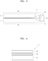
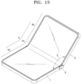
- FIG. 1 is a perspective view illustrating an outer appearance of a foldable device 100 according to an exemplary embodiment.
- FIG. 2 is a side view illustrating a state where the foldable device 100 of FIG. 1 unfolds, according to an exemplary embodiment.
- FIG. 3 is a side view illustrating a state where the foldable device 100 of FIG. 1 folds, according to an exemplary embodiment.
- the flexible display 4 is supported by the first body 1 and the second body 2.
- the flexible display 4 may be divided into a first part 4a that is supported by the first body 1, a second part 4b that is supported by the second body 2, and a third part 4c between the first body 1 and the second body 2.
- the flexible display 4 may be adhered to the first body 1 and the second body 2 by using an adhesive unit such as an adhesive or a double-sided tape.
- the third part 4c of the flexible display 4 may not be supported by the first body 1 or the second body 2. That is, the third part 4c is not adhered to the first body 1 and the second body 2.
- the foldable device 100 may be a portable mobile device such as a communication terminal, a game player, a multimedia device, a portable computer, a persona digital assistance, a photographing apparatus, etc. However, it is understood that one or more other exemplary embodiments are not limited thereto, and the foldable device 100 may be any device including the first body 1 that supports the first part 4a of the flexible display 4 and the second body 2 that supports the second part 4b of the flexible display 4 and is foldably connected to the first body 1.
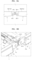
- FIG. 4 is a cross-sectional view illustrating the flexible display 4 according to an exemplary embodiment.
- the flexible display 4 may include a flexible display panel 41 that displays an image and a transparent protective panel 43 that is disposed outside the flexible display panel 41.
- the flexible display panel 41 may be, for example, an organic light-emitting diode (OLED) panel.
- OLED organic light-emitting diode
- an organic emission layer may be disposed between an upper substrate and a lower substrate.
- a polarization plate may be disposed on the upper substrate from which light is emitted.
- the flexible display 4 may further include a touch panel 42 as an input unit (e.g., inputter or input device).
- the touch panel 42 may be disposed between the transparent protective panel 43 and the flexible display panel 41.
- the flexible display panel 41, the touch panel 42, and the transparent protective panel 43 may be adhered to one another by using an optically-clear adhesive (OCA) layer.
- OCA optically-clear adhesive
- the flexible display 4 may further include any of various other optical panels or optical films.
- a processing unit e.g., processor
- an input/output unit e.g., input/output device
- the processing unit may include an image/audio information processing unit (e.g., image/audio information processor).
- the processing unit may include a communication module (e.g., communicator).
- the input/output unit may include an image/audio input/output unit (e.g., image/audio input/output device) and a manipulation unit (e.g., manipulator or manipulation device) for user manipulation.
- the manipulation unit may be realized by using the touch panel 42 of the flexible display 4.
- FIG. 5 is an exploded perspective view illustrating the foldable device 100 of FIG. 1 , according to an exemplary embodiment.
- FIG. 6 is a detailed perspective view illustrating a portion "A" of FIG. 5 , according to an exemplary embodiment.
- FIG. 7 is a cross-sectional view taken along line B-B' of FIG. 6 , according to an exemplary embodiment.
- the first receiver 122 and the second receiver 222 face each other when the first body 1 and the second body 2 are in the folded position of FIG. 3 , to form a receiving space in which the curved portion 4d is received.
- the first receiver 122 and the second receiver 222 are respectively inclined downward from the first support 121 and the second support 221 to be far from the third part 4c of the flexible display 4.
- the third part 4c of the flexible display 4 tends to be slightly bent downward. Since the first receiver 122 and the second receiver 222 are inclined downward from the first support 121 and the second support 221, the third part 4c of the flexible display 4 may be naturally bent downward.
- a stress applied to the flexible display 4 when the first body 1 and the second body 2 change from the unfolded position to the folded position may be reduced and the risk of damage to the flexible display 4 may be reduced.
- the first support 121 and the second support 221 extend to the first receiver 122 and the second receiver 222, the third part 4c of the flexible display 4 may be bent upward, instead of downward, thereby increasing the risk of damage to the third part 4c of the flexible display 4.
- a hinge unit 3 foldably connects the first body 1 and the second body 2.
- the first body 1 and the second body 2 respectively pivot about two central axes 30-1 and 30-2 that are spaced apart from each other.
- the hinge unit 3 may include a connection bracket 31 in which one pair of first connection holes 32-1 and 32-2 are formed, and one pair of hinge members 34-1 and 34-2 that pass through second connection holes 33-1 and 33-2 respectively formed in the first body 1 and the second body 2 and are inserted into the one pair of first connection holes 32-1 and 32-2.
- the second connection holes 33-1 and 33-2 may be respectively formed in both side walls 12a and 22a of the first frame 12 and the second frames 22 or both side walls 11a and 21a of the first base cover 11 and the second base cover 21.
- a cover member 5 surrounds a connecting portion between the first body 1 and the second body 2 to prevent the inside of the foldable device 100 from being exposed to the outside.
- the cover member 5 may include an extending portion 51 that extends along facing edges 13 and 23 of the first body 1 and the second body 2 and side walls 52 that are located on both ends of the extending portion 51.
- Recesses 53 that are sunken from inner surfaces of the side walls 52 are formed (e.g., provided) in the inner surfaces of the side walls 52.
- the recesses 53 are shaped so that the connection bracket 31 may be inserted into each of the recesses 53.
- the cover member 5 may be coupled to the first body 1 and the second body 2 by slightly widening outward the side walls 52 and inserting the connection bracket 31 into the recesses 53.
- the facing edges 13 and 23 of the first body 1 and the second body 2 may be spaced apart from each other, and the inside of the foldable device 100 may be exposed through a space between the facing edges 13 and 23 that are spaced apart from each other.
- the cover member 5 covers the space between the facing edges 13 and 23 in order to prevent the inside of the foldable device 100 from being exposed. Accordingly, the outer appearance of the foldable device 100 may be improved (e.g., aesthetically improved).
- a bottom surface 5a of the cover member 5 does not project beyond bottom surfaces 1a and 2a of the first body 1 and the second body 2. That is, the bottom surface 5a of the cover member 5 is more inwardly curved than the bottom surfaces 1a and 2a of the first body 1 and the second body 2. If the bottom surface 5a of the cover member 5 projects beyond the bottom surfaces 1a and 2a of the first body 1 and the second body 2, the foldable device 100 may unstably move like a seesaw by using the bottom surface 5a of the cover member 5 as a support point. In the configuration of FIG. 2 , when the first body 1 and the second body 2 unfold, the bottom surfaces 1a and 2a of the first body 1 and the second body 2 may be simultaneously stably supported on, for example, a table.
- thicknesses of connecting portions of the first body 1 and the second body 2 that are close to the hinge unit 3 are less than those of the opposite portions. That is, thicknesses of the first body 1 and the second body 2 decrease toward the hinge unit 3.
- a structure in which the bottom surface 5a of the cover member 5 does not project beyond the bottom surfaces 1a and 2a of the first body 1 and the second body 2 may be easily formed (e.g., provided).
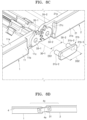
- FIG. 8A is a side view illustrating a gear connection structure that is a modification of a structure for foldably connecting the first body 1 and the second body 2.
- FIG. 8B is a partial exploded perspective view illustrating the gear connection structure of FIG. 8A , according to an exemplary embodiment.
- FIG. 8C is a partial exploded perspective view illustrating the gear connection structure of FIG. 8A , according to another exemplary embodiment.
- FIG. 8D is a side view illustrating a state where the first body 1 and the second body 2 are misaligned with each other in an unfolded state.
- the gear connection structure of FIGS. 8A through 8C may be obtained by adding gears to the structure of FIG. 6 .
- a first gear 35-1 and a second gear 35-2 that engage with each other are respectively provided on the first body 1 and the second body 2. Centers of the first gear 35-1 and the second gear 35-2 respectively correspond to centers of the second connection holes 33-1 and 33-2.
- the first gear 35-1 and the second gear 35-2 are formed on the both side walls 11a and 21a of the first base cover 11 and the second base cover 21, respectively.
- the first gear 35-1 and the second gear 35-2 may be formed on the both side walls 12a and 22a of the first frame 12 and the second frame 22, respectively.
- first body 1 and the second body 2 may be coupled to the connection bracket 31 so that the first body 1 and the second body 2 may pivot about the insertion portions 34a of the hinge members 34-1 and 34-2.
- the cover member 5 covers the connection bracket 31 and the first gear 35-1 and the second gear 35-2.
- the recesses 53 that are sunken from the side walls 52 of the cover member 5 are shaped to receive the connection bracket 31, the first gear 35-1, and the second gear 35-2.
- the connection member 31b includes a bracket portion 31b-3 that is disposed outside the first gear 35-1 and the second gear 35-2, and insertion shafts 31b-1 and 31b-2 that extend from the bracket portion 31b-3 and are inserted into centers of the first gear 35-1 and the second gear 35-2, that is, into the second connection holes 33-1 and 33-2.
- the insertion shafts 31b-1 and 31b-2 are respectively inserted into the second connection holes 33-1 and 33-2.
- the cover member 5 may be coupled to the first body 1 and the second body 2 by slightly widening outward the side walls 52 and inserting the connection member 31b into the recesses 53 (see FIG. 5 ). Accordingly, the side walls 52 of the cover member 5 may prevent the connection member 31b from being separated outward and a state where the insertion shafts 31b-1 and 31b-2 are inserted into the second connection holes 33-1 and 33-2 may be maintained.
- the first gear 35-1 and the second gear 35-2 are covered by the side walls 52 of the cover member 56.
- the recesses 53 may be shaped to receive even the first gear 35-1 and the second gear 35-2.
- the connection member 31b of the present exemplary embodiment may also be applied to the gear connection structure of FIG. 8B .
- an interaxial distance DS1 that is, a distance between the central axes 30-1 and 30-2, is to be maintained.
- the interaxial distance DS1 depends on a distance DS2 between the insertion shafts 31b-1 and 31b-2 provided on the connection member 31b and a difference between diameters of the insertion shafts 31b-1 and 31b-2 and diameters of the second connection holes 33-1 and 33-2.
- a tolerance of the distance DS2 between the insertion shafts 31b-1 and 31b-2 and a tolerance of the difference between the diameters of the insertion shafts 31b-1 and 31b-2 and the second connection holes 33-1 and 33-2 may negatively affect the interaxial distance DS2.
- first body 1 and the second body 2 may be misaligned with each other in an unfolded state, as shown in FIG. 8D .
- the first body 1 and the second body 2 may be misaligned with each other even due to an elastic force applied from an elastic unit that will be described below.
- a level difference 4e may occur in the third part 4c of the flexible display 4.
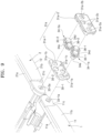
- FIG. 9 is an exploded perspective view illustrating a modification of the hinge unit 3 for foldably connecting the first body 1 and the second body 2.
- the hinge unit 3 includes one pair of hinge members 34-1a and 34-2a on which the first gear 35-1 and the second gear 35-2 are formed and one pair of idle gears 36-1 and 36-2 that connect the first gear 35-1 and the second gear 35-2.
- the one pair of hinge members 34-1a and 34-2a are respectively connected to the first body 1 and the second body 2.
- a connection bracket 31a may include one pair of brackets 31a-1 and 31a-2 that are coupled to each other and form a space in which the first gear 35-1 and the second gear 35-2 and the idle gears 36-1 and 36-2 are received.
- the hinge member 34-1a includes a shaft 34d that extends along the central axis 30-1 and the first gear 35-1 that is provided on the shaft 34d.
- An insertion portion 34e that is inserted into the first body 1, for example, a connection hole 33-1a formed in the side wall 11a of the first base cover 11, is provided on one end portion of the shaft 34d. Shapes of the connection hole 33-1a and the insertion portion 34e are determined or provided so that the hinge member 34-1a rotates along with the first body 1.
- the connection hole 33-1a and the insertion portion 34e have quadrangular cross-sectional shapes.
- the hinge member 34-2a includes the shaft 34d that extends along the central axis 30-2 and the second gear 35-2 that is provided on the shaft 34d.
- the insertion portion 34e that is inserted into the second body 2, for example, a connection hole 33-2a formed in the side wall 21a of the second base cover 21, is provided on one end portion of the shaft 34d. Shapes of the connection hole 33-2a and the insertion portion 34e are determined so that the hinge member 34-2a rotates along with the second body 2.
- the connection hole 33-2a and the insertion portion 34e have quadrangular cross-sectional shapes.
- the insertion portions 34e of the one pair of hinge members 34-1a and 34-2a may pass through support-holes 31a-1a and 31a-1b of the bracket 31a-1 and may be respectively inserted into the connection holes 33-1a and 33-2a formed in the side walls 11a and 21a, and the bracket 31a-2 may be coupled to the bracket 31a-1.
- the hinge member 34-1a passes through the support holes 31a-1a and 31a-2a of the brackets 31a-1 and 31a-2
- the hinge member 34-2a passes through the support holes 31a-1b and 31a-2b of the brackets 31a-1 and 31a-2.
- the connection bracket 31a may be pivotably connected to the one pair of hinge members 34-1a and 34-2a.
- the idle gears 36-1 and 36-2 are pivotably supported in support holes 31a-1c and 31a-2c formed in the one pair of brackets 31a-1 and 31a-2.
- FIG. 10 is an exploded perspective view illustrating another modification of the hinge unit 3 for foldably connecting the first body 1 and the second body 2.
- the hinge unit 3 of FIG. 10 is similar to the hinge unit 3 of FIG. 9 , though the connection bracket 31a of FIG. 9 is replaced with a connection bracket 31a'. That is, the bracket 31a-2 including the support holes 31a-2c of FIG. 9 is replaced with a bracket 31a-2' including support posts 31a-2c'. Also, concave portions 36-5 into which the support posts 31a-2c' are inserted are formed in the idle gears 36-3 and 36-4.
- the first body 1 and the second body 2 may be connected to each other to change between the unfolded position of FIG. 2 and the folded position of FIG. 3 .
- a lubricant applied to the first gear 35-1 and the second gear 35-2 may be prevented from being exposed to the outside and from being contaminated with dust.
- the cover member 5 covers the connection bracket 31a or 31a'.
- the recesses 53 formed in the side walls 52 of the cover member 5 are shaped to receive the connection bracket 31a.
- FIG. 12 is a cross-sectional view taken along line C-C' of FIG. 5 , according to an exemplary embodiment.
- the elastic arm 61 and the facing arm 62 respectively extend from the first base cover 11 and the second base cover 21 and face each other.
- the elastic arm 61 includes a first contact portion 61-1 that contacts a facing portion 62a of the facing arm 62 when the first body 1 and the second body 2 are in the unfolded position.
- the first contact portion 61-1 and the facing portion 62a of the present exemplary embodiment have planar shapes.
- the first contact portion 61-1 is inclined at an angle D1 with respect to the facing portion 62a.
- FIG. 15 is a cross-sectional view illustrating the elastic unit according to another exemplary embodiment.
- the facing arm 62 may contact the elastic arm 61 and may be elastically deformed.
- the elastic arm 61 and the facing arm 62 are respectively referred to as a first elastic arm 61 and a second elastic arm 62.
- the first elastic arm 61 is the same as the elastic arm 61 of FIG. 12 .
- the second elastic arm 62 may be integrally formed with the second frame 22 of the second body 2.
- the facing portion 62a may include a first facing portion 62-1 and a second facing portion 62-2 having planar shapes and respectively corresponding to the first contact portion 61-1 and the second contact portion 61-2.
- the second facing portion 62-2 is distinguished from the first facing portion 62-1 by a boundary portion 62-3 that projects most toward the first body 1.
- the first body 1 and the second body 2 are in the position having the unfolding angle E of FIG. 13
- the second contact portion 61-2 and the second facing portion 62-2 surface-contact each other, and the first elastic arm 61 and the second elastic arm 62 are elastically deformed to push each other.
- the first contact portion 61-1 and the first facing portion 62-1 may surface-contact each other to push each other, the flexible display 4 may be spread flat, and the first body 1 and the second body 2 may be maintained at the completely unfolded position.
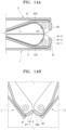
- FIG. 16 is a cross-sectional view illustrating the elastic unit according to another exemplary embodiment.
- a first elastic arm 61' having a leaf spring shape and including the first contact portion 61-1 and the second contact portion 61-2 may be coupled to the first body 1, for example, the first frame 12.
- a second elastic arm 62' having a leaf spring shape and including the first facing portion 62-1 and the second facing portion 62-2 may be coupled to the second body 2, for example, the second frame 22.
- FIG. 17 is a cross-sectional view illustrating the elastic unit according to another exemplary embodiment.
- an elastic arm (first elastic arm) 61" including a first contact portion 61-1" and a second contact portion 61-2" having curved shapes is elastic, has a leaf spring shape, and is coupled to the first body 1, for example, the first frame 21.
- the first contact portion 61-1" and the second contact portion 61-2" are distinguished from each other by a boundary portion 61-3" that projects most toward the second body 2.
- a facing arm (second elastic arm) 62" including a first facing portion 62-1" and a second facing portion 62-2" having curved shapes respectively corresponding to the first contact portion 61-1" and the second contact portion 61-2” is elastic, has a leaf spring shape, and is coupled to the second body 2, for example, the second frame 22.
- the first facing portion 62-1" and the second facing portion 62-2" are distinguished from each other by a boundary portion 62-3" that projects most toward the first body 1.
- FIGS. 18A , 18B, and 18C are cross-sectional views illustrating an initial state where the first body 1 and the second body 2 begin to unfold and the elastic arm 61" contacts the facing arm 62", a state where the first body 1 and the second body 2 are maintained at a predetermined unfolding angle, and a state where the first body 1 and the second body 2 completely unfold. How the first body 1 and the second body 2 fold and unfold will now be explained with reference to FIGS. 18A through 18C .
- the elastic arm 61" and the facing arm 62" are spaced apart from each other.
- the elastic arm 61" contacts the facing arm 62.
- the elastic arm 61" and the facing arm 62 may surface-contact each other. Accordingly, the problem that the first body 1 and the second body 2 are misaligned with each other as shown in FIG. 8D in the connection structure not including the first gear 35-1 and the second gear 35-2 may be reduced by minimizing a vertical component F2 of an elastic force and maximizing a horizontal component F1 of the elastic force.
- the elastic arm 61" is pushed by the facing arm 62" and begins to be elastically deformed.
- a stiffness of the flexible display 4 and the elastic force applied due to the deformation of the elastic arm 61" and the facing arm 62" are balanced, and thus even when an external force for making the first body 1 and the second body 2 unfold is removed, the angle between the first body 1 and the second body 2 is maintained at the unfolding angle E. Even when the first body 1 and the second body 2 further unfold, unless the first body 1 and the second body 2 unfold at an angle exceeding the boundary portions 61-3" and 62-3", the first body 1 and the second body 2 return to the unfolding angle E due to the elastic force of the elastic arm 61" and the facing arm 62".
- the first body 1 and the second body 2 synchronously pivot during a folding/unfolding process.
- the elastic arm 61' or 61" and the facing arm 62' or 62" are symmetric with each other about a center of a line that connects the central axes 30-1 and 30-2 of the first body 1 and the second body 2.
- the elastic arm 61' or 61" and the facing arm 61' or 61" are not misaligned with each other, stably contact each other, and thus may be elastically deformed in desired directions.
- the foldable device 100 may further include a movable supporting member 7 (e.g., movable supporter).
- the movable supporting member 7 includes movable supports 71 that support the third part 4c of the flexible display 4.
- the movable supports 71 may be disposed on both sides in a width direction W and may partially support the third part 4c of the flexible display 4.
- the movable supporting member 7 is located at a support position where the movable supports 71 support the third part 4c of the flexible display 4 when the first body 1 and the second body 2 are in the unfolded position.
- the movable supporting member 7 supports the third part 4c of the flexible display 4 between the first receiver 122 and the second receiver 222.
- the movable supporting member 7 is located at a retreat position to form the receiving space of the curved portion 4d. That is, the movable supporting member 7 moves between the retreat position and the support position as the first body 1 and the second body 2 change between the folded position and the unfolded position.
- the third part 4c may be spread flat.
- the movable supporting member 7 may be raised from the retreat position to the support position to continuously near-support the third part 4c of the flexible display 4.
- the expression 'continuously near-support' means that while the foldable device 100 folds/unfolds, the movable supporting member 7 continuously supports the third part 4c of the flexible display 4 or is raised/retreated to the position that supports the third part 4c of the flexible display 4 that is bent or spread.
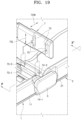
- FIG. 19 is an exploded perspective view illustrating a structure for moving the movable supporting member 7 between the support position and the retreat position, according to an exemplary embodiment.
- slots 72 that extend in a folding/unfolding direction in which the first body 1 and the second body 2 fold/unfold are formed in the movable supporting member 7.
- One pair of guide portions 73-1 and 73-2 that are inserted into the slots 72 are formed around facing edges of the first body 1 and the second body 2 that are adjacent to the hinge unit 3.
- the guide portions 73-1 and 73-2 may be respectively provided on upper ends of ribs 74-1 and 74-2 that respectively extend upward from the first frame 12 and the second frame 22.
- Insertion grooves 75 for inserting the guide portions 73-1 and 73-2 into the slots 72 are formed in the movable supporting member 7.
- the insertion grooves 75 are formed at central portions of the slots 72 in a longitudinal direction 72L of the slots 72. While the first body 1 and the second body 2 fold/unfold, the guide portions 73-1 and 73-2 move in the longitudinal direction 72L of the slots 72. However, the guide portions 73-1 and 73-2 do not move to overlap with the insertion grooves 72. Accordingly, while the movable supporting member 7 is elevated after the guide portions 73-1 and 73-2 are inserted into the slots 72, the guide portions 73-1 and 73-2 are not separated from the slots 72 through the insertion grooves 75.
- FIGS. 20A, 20B , and 20C are cross-sectional views taken along line F-F' of FIG. 19 , illustrating respectively states where the movable supporting member 7 is located at the support position and the retreat position, according to an exemplary embodiment.
- the first body 1 and the second body 2 are in the folded position.
- the guide portions 73-1 and 73-2 are farthest away from each other, and the movable supporting member 7 is located at the retreat position.
- the curved portion 4d of the flexible display 4 is received in a space formed by the first receiver 122, the second receiver 222, and the movable supporting member 7.
- the movable supporting member 7 When the first body 1 and the second body 2 completely unfold as shown in FIG. 20C , the movable supporting member 7 is located at the support position and the third part 4c of the flexible display 4 is stably supported by the movable support 71.
- portions of the third part 4c of the flexible display 4 corresponding to the first receiver 122 and the second receiver 222 between the first support 121 and the second support 221 and the movable supporting member 7 are not supported by another member when the first body 1 and the second body 2 are located at the unfolded position. That is, the third part 4c of the flexible display 4 includes a central portion 4c-3 that is supported by the movable supporting member 7 and both side portions 4c-1 and 4c-2 that are not supported by another member.
- the third part 4c of the flexible display 4 tends to be bent downward, that is, convexly toward the first body 1 and the second body 2.
- the problem that the third part 4c is not convexly bent downward but is convexly bent upward due to a lack of the amount of the movable supporting member 7 that retreats may be solved.
- the first body 1 and the second body 2 may be maintained in the folded state, thereby improving portability and storage.
- a distance between the shaft and the first post is RA1
- a distance between the first post and the second post is RA2
- a distance between the neutral surface of the flexible display and the neutral surface of the guide member is d12
- a distance between the neutral surface of the flexible display and the neutral surface of the hinge unit is d13
- the hinge unit may be connected to the first body and the second body to move relative to the first body and the second body
- the guide member may be connected to the first body and the second body to move relative to the first body and the second body
- the hinge unit may be connected to the first body and the second body to move relative to the first body and the second body.
- the hinge unit may move in a symmetric matter relative to the first body and the second body.
- the hinge unit may include a first connection portion and a second connection portion that are respectively connected to the first body and the second body
- the guide member may include first and second guide members that are spaced apart from each other in a width direction perpendicular to a folding/unfolding direction, one end portion of the first guide member may be fixed to the first body and the other end portion of the first guide member may be connected to the second connection portion to move relative to the second body along with the hinge unit, and one end portion of the second guide member may be fixed to the second body and the other end portion of the second guide member may be connected to the first connection portion to move relative to the first body along with the hinge unit.
- a foldable device includes: a first body and a second body; a flexible display that is supported on the first body and the second body; a hinge unit that is disposed between the first body and the second body, foldably connects the first body and the second body, and is connected to the first body and the second body to move relative to the first body and the second body; and a movement limiting unit that maintains the first body and the second body symmetric with each other about the hinge unit during a folding/unfolding process.
- the hinge unit may include a first connection portion and a second connection portion that are respectively connected to the first body and the second body
- the movement limiting unit may include a first guide member whose one end portion is fixed to the first body and whose other end portion is connected to the second connection portion and moves relative to the second body along with the hinge unit, and a second guide member that is spaced apart from the first guide member in a width direction perpendicular to a folding/unfolding direction and whose one end portion is fixed to the second body and whose other end portion is connected to the first connection portion and moves relative to the first body along with the hinge unit.
- the first guide member and the second guide member may be spaced apart from each other in the width direction that intersects the folding/unfolding direction.
- the first guide member and the second guide member may have sheet shapes that may be elastically bent.
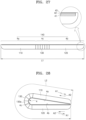
- FIG. 26 is a perspective view illustrating an outer appearance of a foldable device according to an exemplary embodiment.
- FIG. 27 is a side view illustrating a state where the foldable device of FIG. 26 unfolds, according to an exemplary embodiment.
- FIG. 28 is a side view illustrating a state where the foldable device of FIG. 26 folds, according to an exemplary embodiment.
- the foldable device includes a body, a flexible display 140, and a hinge unit 130.
- the body includes a first body 110 and a second body 120.
- the flexible display 140 is supported by the first body 110 and the second body 120.
- the flexible display 140 may be adhered to the first body 110 and the second body 120 by using an adhesive unit such as an adhesive or a double-sided tape.
- the hinge unit 130 is disposed between the first body 110 and the second body 120 and foldably connects the first body 110 and the second body 120.
- a folding/unfolding direction of the first body 110 and the second body 120 is the longitudinal direction L.
- the foldable device may be a portable mobile device such as a communication terminal, a game player, a multimedia device, a portable computer, a personal digital assistant, a photographing apparatus, etc.
- the foldable device may be any device including the first body 110 that supports the first part 4a of the flexible display 140 and the second body 120 that supports the second part 4b of the flexible display 140, wherein the first body 110 and the second body 120 are foldably connected to each other by using the hinge unit 130.
- the flexible display 140 may include the flexible display panel 41 that displays an image and the transparent protective panel 43 that is disposed outside the flexible display panel 41. Also, the flexible display 140 may further include the touch panel 42 as an input unit. The touch panel 42 may be disposed between the transparent protective panel 43 and the flexible display panel 41. However, it is understood that one or more other exemplary embodiments are not limited thereto, and the flexible display 4 may further include any of various other optical panels or optical films.
- a processing unit e.g., processor
- an input/output unit e.g., input/output device
- the processing unit may include an image/audio information processing unit.
- the processing unit may include a communication module.
- the input/output unit may include an image/audio input/output unit (e.g., image/audio input/output device) and a manipulation unit (e.g., manipulator or manipulation device) for user manipulation.
- the manipulation unit may be realized by using the touch panel 42 of the flexible display 140
- the flexible display 140 may be divided into the first part 4a that is coupled to the first body 110, the second part 4b that is coupled to the second body 120, and the third part 4c between the first body 110 and the second body 120.
- the flexible display 140 may be adhered to the first body 110 and the second body 120 by using an adhesive unit such as an adhesive or a double-sided tape.
- the third part 4c of the flexible display 140 is not fixed to the hinge unit 130.
- the foldable device may fold as shown in FIG. 28 .
- the hinge unit 130 is disposed outside the flexible display 140 to form a curved portion 130a having a predetermined curvature as shown in FIG. 28 .
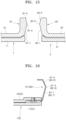
- FIG. 29 is a cross-sectional view illustrating the foldable device according to another exemplary embodiment.
- the hinge unit 130 is connected to the first body 110 and the second body 120 to slide in the longitudinal direction L.
- the hinge unit 130 includes a connection bracket 131 on which a first rail 131a is provided.
- the connection bracket 131 includes first and second connection brackets 131-1 and 131-2.
- the first and second connection brackets 131-1 and 131-2 are respectively disposed on both sides of the hinge unit 130 in the longitudinal direction L.
- the first connection bracket 131-1 is connected to the first body 110 and the second connection bracket 131-2 is connected to the second body 120.
- the distance d12 between the first guide member 150-1 and the second guide member 150-2 and the flexible display 140 in the thickness direction T is equal to the distance d23 between the first guide member 150-1 and the second guide member 150-2 and the hinge unit 130 in the thickness direction T.
- the distance d12 is a distance between the neutral surface NS1 of the flexible display 140 and the neutral surface NS2 of the first guide member 150-1 and the second guide member 150-2 and the distance d23 is a distance between the neutral surface NS2 of the first guide member 150-1 and the second guide member 150-2 and the neutral surface NS3 of the hinge unit 130.
- the neutral surface NS3 of the hinge unit 130 is a surface where there exist central axes of the plurality of connection members 320 about which the plurality of segment members 310 pivot.
- a stress applied to the flexible display 140 during a folding/unfolding process may be reduced due to the first guide member 150-1 and the second guide member 150-2.
- the first body 110 and the second body 120 synchronously move relative to the hinge unit 130 and thus the first body 110 and the second body 120 may be maintained symmetric with each other about the hinge unit 130. That is, the first guide member 150-1 and the second guide member 150-2 operate as a movement limiting unit (e.g., movement limiter) for maintaining the first body 110 and the second body 120 symmetric with each other about the hinge unit 130 by limiting the moving amounts of the first body 110 and the second body 120 relative to the hinge unit 130 during a folding/unfolding process. Accordingly, since the flexile display 140 is not excessively pulled or pushed to one side during a folding/unfolding process, natural folding/unfolding may be achieved and a stress applied to the flexible display 140 may be reduced.
- a movement limiting unit e.g., movement limiter
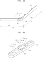
- the foldable device may be asymmetric, and thus the third part 4c of the flexible display 140 may come off from the support surface 301 that is formed by the hinge unit 130 to have the curved shape 4f of FIG. 40 , thereby reducing the beauty of an outer appearance of the foldable device.
- the third part 4c of the flexible display 140 may be permanently deformed. Such a tensile force and such a compressive force may be reduced due to synchronous relative movements of the first body 110 and the second body 120 and the hinge unit 130 and may be further reduced due to the first guide member 150-1 and the second guide member 150-2.
- a flexible display may be stably supported to not be bent during a folding/unfolding process. Since a guide member that elastically bends is disposed between the flexible display and a hinge unit, a stress applied to the flexible display during the folding/unfolding process may be reduced. Since a first body and a second body and the hinge unit move in a symmetric manner, a stress applied to the flexible display during the folding/unfolding process may be reduced and an outer appearance of the foldable device may be improved.
- a mobile terminal device (foldable device) of the present exemplary embodiment improves portability by distributing various electronic parts that are hardly bent on portions corresponding to one side portion and the other side portion of a flexible display that defines a front surface and disposing a flexible hinge between the portions.
- the mobile terminal device of the present exemplary embodiment supports the flexible display so that the flexible display is maintained in a state having a predetermined curvature during a folding process.
- the mobile terminal device of the present exemplary embodiment may be firmly maintained in a folded state and an unfolded state, thereby allowing a user to stably input a touch.
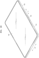
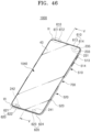
- FIG. 46 is a perspective view illustrating a front surface of a mobile terminal device 1000 according to an exemplary embodiment.
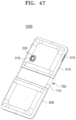
- FIG. 47 is a perspective view illustrating a rear surface of the mobile terminal device 1000 according to an exemplary embodiment.
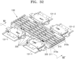
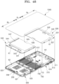
- FIG. 48 is an exploded perspective view illustrating the mobile terminal device 1000 according to an exemplary embodiment.
- FIG. 49 is a cross-sectional view illustrating a flexible display 1040 of FIG. 48 , according to an exemplary embodiment.
- FIG. 50 is a cross-sectional view taken along line V-V of the mobile terminal device 1000 of FIG. 46 , according to an exemplary embodiment.
- the mobile terminal device 1000 includes the flexible display 1040, a first support 530, a second support 540, a first cover 510, a second cover 520, a flexible hinge (e.g., hinge unit) 700, and a communication module 900 (e.g., communication terminal or communicator).
- a flexible hinge e.g., hinge unit
- a communication module 900 e.g., communication terminal or communicator
- a structure of the mobile terminal device 1000 constructed as described above will be explained below and then elements will be sequentially explained in detail.
- the flexible display 1040 has a degree of freedom high enough to be bent to a predetermined curvature.
- the third part 4c formed between the first part 4a and the second part 4b is bent.
- the first support 530 and the second support 540 each formed of (e.g., including) a hard material, even when a user touches a front surface of the flexible display 1040, the flexible display 1040 may not be pushed backward and a touch may be stably input.
- the first cover 510 and the second cover 520 to which the first support 530 and the second support 540 are respectively coupled are connected to each other via the flexible hinge 700.
- the first cover 510 and the second cover 520 and the flexible hinge 700 form the rear surface of the mobile terminal device 1000. That is, the first cover 510, the second cover 520, and the flexible hinge 700 are integrated to form a single cover unit.
- a charged battery 200 (see FIG. 50 ) and a main printed circuit board (PCB) 210 (see FIG. 50 ) are disposed between the first cover 510 and the second cover 520 and the first support 530 and the second support 540.
- a central processing unit (CPU) and the communication module 900 may be mounted on the main PCB 210 and the communication module 900 is electrically connected to an antenna.
- the flexible hinge 700 may be bent so that the third part 4c of the flexible display 1040 has a predetermined curvature.
- the predetermined curvature of the third part 4c may be small enough to not physically damage the flexible display 1040.
- a structure of the mobile terminal device 1000 will now be explained in detail.
- the flexible display 1040 is formed by sequentially stacking the transparent protective panel 43 (hereinafter, referred to as a cover window 43), the touch panel 42, and the flexible display panel 41 from the front to the back.
- a cover window 43 the transparent protective panel 43
- the touch panel 42 the touch panel 42
- the flexible display panel 41 from the front to the back.
- the cover window 43 is a plastic or film cover window. Portions (specifically, outer portions) of the cover window 43 corresponding to the first part 4a and the second part 4b of FIG. 48 are supported by the first support 530 and the second support 540. In this case, the outer portions of the cover window 43 may not be fixed (or attached) to top surfaces 531 and 541 of the first support 530 and the second support 540, or may be fixed (or attached) to the top surfaces 531 and 541 of the first support 530 and the second support 540 to slightly move relative to the first support 530 and the second support 540.
- the cover window 43 may have a pattern formed of a soft metal mesh, silver nanowires (AgNW), or graphene.
- the touch panel 42 is attached to a rear surface of the cover window 43 by using an optically-clear adhesive (OCA) 44-1.
- OCA optically-clear adhesive
- the touch panel 42 detects a user's touch gesture and transmits a touch input signal to the main PCB 210.
- a first flexible printed circuit board (FPCB) 42-1 on which a driving integrated circuit (IC) for driving the touch panel 42 is mounted is electrically connected to one side of the touch panel 42.
- the first FPCB 42-1 is electrically connected to a second FPCB 41-1 of the flexible display panel 41 through a first connector 42-3.
- the first connector 42-3 may be directly connected to the main PCB 210 (see FIG. 50 ) that is disposed on a rear surface of the first support 530.
- the first FPCB 42-1 may have a length greater than that in FIG. 49 so that the first connector 42-3 may pass through a through-hole 532( FIG. 48 ) of the first support 530 to be electrically connected to the main PCB 210.
- the flexible display panel 41 is attached to the rear surface of the cover window 43, or a rear surface of the touch panel 42 if any, by using an OCA 44-3.
- the flexible display panel 41 may be an active matrix organic light-emitting diode (AMOLED) panel or a flexible OLED panel.
- AMOLED active matrix organic light-emitting diode
- the second FPCB 41-1 on which a driving IC for driving the flexible display panel 41 is mounted is electrically connected to one side of the flexible display panel 41.
- a second connector 41-3 may be provided on one end of the second FPCB 41-1, and may pass through the through-hole 532 ( FIG. 48 ) of the first support 530 to be electrically connected to the main PCB 210 (see FIG. 50 ) that is disposed on the rear surface of the first support 530.
- the second FPCB 41-1 may have a length enough to allow the mobile terminal device 1000 to fold/unfold.
- the flexible display panel 41 is disposed on the rear surface of the touch panel 42 in the present exemplary embodiment, it is understood that one or more other exemplary embodiments are not limited thereto and the flexible display panel 41 may be stacked on a front surface of the touch panel 42.
- the flexible display panel 41 is attached to front surfaces of the first support 530 and the second support 540 by using adhesive members 44-4 and 44-5 that are respectively attached to one side portion and the other side portion of a rear surface of the flexible display panel 41.
- the adhesive members 44-4 and 44-5 may be double-sided adhesive tapes thin enough for the mobile terminal device 1000 to have a low thickness or double-sided adhesive tapes having predetermined cushioning properties.
- portions of the flexible display panel 41 corresponding to the first part 4a and the second part 4b other than a portion corresponding to the third part 4c of FIG. 48 are respectively fixed to the first support 530 and the second support 540. Accordingly, when the mobile terminal device 1000 folds and the third part 4c of the flexible display 1040 is bent, the flexible display 1040 is not affected by the adhesive members 44-4 and 44-5, thereby allowing the mobile terminal device 1000 to smoothly fold.
- the first support 530 and the second support 540 are formed of (e.g., include) a hard material and include planar front surfaces in order to stably support the flexible display 1040.
- a plurality of coupling grooves K1 that are arranged at intervals along outer ends of the first support 530 and the second support 540 are formed in the first support 530 and the second support 540.
- a plurality of coupling protrusions K2 that protrude at intervals along inner ends of the first cover 510 and the second cover 520 are snap-fitted to the plurality of coupling grooves K1. Accordingly, the first support 530 and the second support 540 may be respectively detachably coupled to the first cover 510 and the second cover 520.
- the charged battery 200, a memory, and a subscriber identity module (SIM) card may be inserted/taken into/from first and second spaces S1 and S2 by respectively separating the first cover 510 and the second cover 520 from the first support 530 and the second support 540.
- SIM subscriber identity module
- the first space S1 is formed as the first support 530 is coupled to the first cover 510 and the rear surface of the first support 530 that faces a front surface of the first cover 510 is spaced from the front surface of the first cover 510.
- the main PCB 210 may be disposed in the first space S1, and various electronic parts such as a rear camera module 220 (e.g., rear camera) (see FIG. 47 ), a proximity sensor 231, an illumination sensor 233, a front camera module 235 (e.g., front camera), and a speaker may be disposed in the first space S1 (see FIG. 46 ).
- the proximity sensor 231, the illumination sensor 233, and the front camera module 235 are disposed to face the front of the cover window 43 through a first through-groove 533 ( FIG. 48 ) formed in the first support 530 and the rear camera module 220 is disposed to face the back of the first cover 510 through a through-hole 516 (see FIG. 47 ) of the first cover 510.
- the second space S2 is formed as the second support 540 is coupled to the second cover 520 and a rear surface of the second support 540 that faces a front surface of the second cover 520 is spaced apart from the front surface of the second cover.
- the charged battery 200 (see FIG. 50 ) and a tiny microphone 230 (see FIG. 48 ) may be disposed in the second space S2.
- a microphone hole 236 ( FIG. 48 ) is formed in the second cover 520 so that a sound such as voice is input to the tiny microphone 230.
- a plurality of concave grooves 543 and 544 on which a plurality of soft keys 241 and 242 for transmitting a touch input signal to a CPU are disposed in order to control the flexible display panel 41 are formed in an outer portion of the front surface of the second support 540.
- the plurality of soft keys 241 and 242 that are touch sensors are protected by the cover window 43.
- a second through-groove 535 and a third through-groove 545 through which a third FPCB 800 (see FIG. 55 ) passes are respectively formed in facing end portions of the first support 530 and the second support 540.
- the third FPCB 800 may electrically connect the charged battery 200, the tiny microphone 230, and the plurality of soft keys 241 and 242 disposed in the second space S2 to the main PCB 210 disposed in the first space S1.
- the adhesive members 44-4 and 44-5 are attached to the first support 530 and the second support 540 so that the back of the flexible display 1040 is fixed to concave grooves 537 and 547 that are respectively formed in the front surfaces of the first support 530 and the second support 540.
- the back of the flexible display 1040 is received in the concave grooves 537 and 547, thereby preventing a thickness of the mobile terminal device 1000 from being increased.
- the first cover 510 and the second cover 520 are each formed of (e.g., include) a hard material, and are connected to each other by using the flexible hinge 700.
- one pair of packings 511 and 512 for supporting the first support 530 are disposed at both corners of a front end portion of the first cover 510.
- a first control button 513 and a second control button 514 are disposed along one side end of the first cover 510 and a third control button 515 (see FIG. 47 ) is disposed on the other side end that is opposite to the one side end.
- the first through third control buttons 513, 514, and 515 may be set to turn on/off a screen of the flexible display 1040, to control a brightness of the screen, to control a volume of the speaker, etc.
- the first through third control buttons 513, 514, and 515 may be set to work with various applications of the memory provided in the mobile terminal device 1000.
- One pair of second packings 521 and 522 for supporting the second support 540 are disposed at both corners of a front end portion of the second cover 520, like in the first cover 510.
- an insertion hole 523 into which an earphone jack is inserted may be formed in one side end of the second cover 520 and a plurality of antennas may be disposed on an inner surface of the second cover 520.
- the antennas that are for wireless communications may include long-distance antennas that may communicate with other terminals through base stations or access points (APs), and short-distance antenna such as Wi-Fi antennas, near field communication (NFC) antennas, etc.
- a first locking portion 610 and a second locking portion 620 that are coupled to each other when the mobile terminal device 1000 is closed are respectively disposed on the front end portions of the first cover 510 and the second cover 520.
- the first locking portion 610 and the second locking portion 620 may be coupled to each other due to a magnetic force.
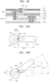
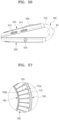
- FIG. 51 is an enlarged view illustrating the first locking portion 610 in a portion VI of FIG. 46 , according to an exemplary embodiment.
- FIG. 52 is an enlarged view illustrating the second locking portion 620 in a portion VII of FIG. 46 , according to an exemplary embodiment.
- FIG. 53 is an enlarged view illustrating a state where the first locking portion 610 and the second locking portion 620 of FIG. 46 are coupled to each other due to a magnetic force, according to an exemplary embodiment.
- the first magnet 611 that is convex is attached to the fifth magnet 621 that is concave
- the first magnet 611 and the fifth magnet 621 are coupled to each other due to not only a magnetic force but also a convex-concave (uneven) joint structure.
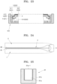
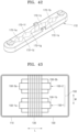
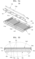
- FIG. 54 is a perspective view illustrating the flexible hinge 700 of FIG. 48 , according to an exemplary embodiment.
- FIG. 55 is an enlarged view illustrating a part of the flexible hinge 700 in a portion X of FIG. 50 , according to an exemplary embodiment.
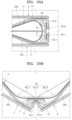
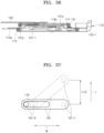
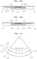
- FIG. 56 is a side view illustrating a state where the mobile terminal device 1000 folds, according to an exemplary embodiment.
- FIG. 57 is an enlarged cross-sectional view illustrating a state where the flexible hinge 700 in a portion XII of FIG. 56 is bent, according to an exemplary embodiment.
- a configuration of the flexible hinge 700 will now be explained in detail with reference to FIGS. 54 through 57 .
- an outer portion 710 and an inner portion 730 of the flexible hinge 700 may be formed by using double-shot injection molding.
- the outer portion 710 may be formed of (e.g., include) a soft material (e.g., soft plastic or polymer).
- the outer portion 710 may have a stiffness enough to be naturally bent when the mobile terminal device 1000 folds as shown in FIG. 56 and enough to allow the mobile terminal device 1000 to be maintained straight in a longitudinal direction when the mobile terminal device 1000 does not fold as shown in FIG. 50 .
- the inner portion 730 is integrally formed with an inner peripheral surface of the outer portion 710, and is formed of a hard material (e.g., hard plastic).
- the inner portion 730 includes a plurality of reinforcing members, that is, first through third reinforcing members 731, 732, and 733 that are arranged at predetermined intervals in a folding/unfolding direction of the flexible display 1040 of FIG. 56 .
- front end portions of the first through third reinforcing members 731, 732, and 733 support a rear surface of the third part 4c (see FIG. 48 ) of the flexible display 1040.
- rear end portions of the third reinforcing members 733 are fixedly inserted into a plurality of slits 710a that are formed in the inner peripheral surface of the outer portion 710.
- receiving grooves 731a, 732a, and 733a in which the third FPCB 800 is mounted are formed in the first through third reinforcing members 731, 732, and 733. In this case, the third FPCB 800 is disposed under the flexible display 1040.
- a strain gauge sensor 810 may be disposed in the receiving grooves 731a, 732a, and 733a of the first through third reinforcing members 731, 732, and 733.
- the strain gauge sensor 810 may be connected to the main PCB 210 through a signal line, and may detect the variation of the length of the flexible hinge 700 as the mobile terminal device 1000 folds and may cause the CPU to control the screen of the flexible display 1040.
- the curvature of the flexible hinge 700 may be set in consideration of a desirable amount of bending of the flexible display 1040.
- the desirable amount of bending of the flexible display 1040 is determined so that when the flexible display 1040 folds, the flexible display 1040 is not physically damaged and when the mobile terminal device 1000 unfolds (see FIG. 51 ), the third part 4c is spread flat.
- a rear surface of the flexible display 1040 is stably supported by the first through third reinforcing members 731, 732, and 733 of the flexible hinge 700 as shown in FIG. 57 .
- the communication module 900 may include an electronic device (see FIG. 50 ) such as an LED modem chip that may communicate with other terminals through base stations or APs and may be mounted on the main PCB 210. Also, chips for establishing communication such as Wi-Fi, NFC, Bluetooth, etc., may be provided on the main PCB 210.
- the present exemplary embodiment is described with reference to the mobile terminal device 1000, when the communication module 900 is omitted, the present exemplary embodiment may be applied to a display device for multimedia.
- the flexible display 1040 is supported by the first support 530 and the second support 540 and the inner portion 730 of the flexible hinge 700 each of which is formed of a hard material, a user's touch (for example, flipping, dragging, or typing) may be stably input by making the mobile terminal device 1000 unfold.
Landscapes
- Engineering & Computer Science (AREA)
- Theoretical Computer Science (AREA)
- Computer Hardware Design (AREA)
- Physics & Mathematics (AREA)
- General Physics & Mathematics (AREA)
- Human Computer Interaction (AREA)
- General Engineering & Computer Science (AREA)
- Nonlinear Science (AREA)
- Chemical & Material Sciences (AREA)
- Crystallography & Structural Chemistry (AREA)
- Mathematical Physics (AREA)
- Optics & Photonics (AREA)
- Telephone Set Structure (AREA)
- Devices For Indicating Variable Information By Combining Individual Elements (AREA)
- Casings For Electric Apparatus (AREA)
- Display Racks (AREA)
- Toys (AREA)
Claims (9)
- Faltbare Vorrichtung, umfassend:eine flexible Anzeige (4), die einen ersten Teil (4a), einen zweiten Teil (4b) und einen dritten Teil (4c) zwischen dem ersten Teil (4a) und dem zweiten Teil (4b) in einer Längsrichtung (L) umfasst;einen ersten Körper (1), der so konfiguriert ist, dass er den ersten Teil (4a) unterstützt;einen zweiten Körper (2), der so konfiguriert ist, dass er den zweiten Teil (4b) unterstützt; undein Scharnier (3), das konfiguriert ist, um den ersten Körper (1) und den zweiten Körper (2) faltbar zu verbinden und eine Vielzahl von Segmentelementen (310) zu umfassen, die schwenkbar miteinander verbunden sind und den dritten Teil (4c) unterstützen;wobei das Segmentelement (310) einen oberen Endabschnitt (311) umfasst, der so konfiguriert ist, dass er den dritten Teil (4c) unterstützt;einen unteren Endabschnitt (312), der so konfiguriert ist, dass er gegenüber dem oberen Endabschnitt (311) positioniert ist; undSeitenabschnitte (313, 314), die so konfiguriert sind, dass sie den oberen Endabschnitt (311) und den unteren Endabschnitt (312) verbinden und geneigt sind;wobei, während der erste Körper (1) und der zweite Körper (2) gefaltet sind, der obere Endabschnitt (311) des Segmentelements (310-1) den oberen Endabschnitt (311) des benachbarten Segmentelements (310-2) berührt, um den dritten Teil (4c) zu unterstützen, damit er in eine bestimmte Form gebogen wird, und der Seitenabschnitt (313) des Segmentelements (310-1) den Seitenabschnitt (314) des benachbarten Segmentelements (310-2) berührt, um zu verhindern, dass der dritte Teil (4c) weiter nach innen gebogen wird, unddass, während der erste Körper (1) und der zweite Körper (2) auseinandergefaltet sind, der untere Endabschnitt (312) des Segmentelements den unteren Endabschnitt (312) des benachbarten Segmentelements berührt, um zu verhindern, dass der dritte Teil (4c) weiter nach außen gebogen wird,dadurch gekennzeichnet, dassdas Scharnier (3) in Bezug auf den ersten Körper (1) und den zweiten Körper (2) gleitend verbunden und so konfiguriert ist, dass es in Längsrichtung gleitet.
- Faltbare Vorrichtung nach Anspruch 1, wobei der dritte Teil (4c) gebogen ist, um einer Form des oberen Endabschnitts (311) der Vielzahl von Segmentelementen (310) zu entsprechen.
- Faltbare Vorrichtung nach Anspruch 1, wobei jedes der Vielzahl von Segmentelementen (310) den oberen Endabschnitt (311) umfasst, dessen Breite so konfiguriert ist, dass sie geringer ist als eine Breite des unteren Endabschnitts (312).
- Faltbare Vorrichtung nach Anspruch 1, ferner umfassend:einen ersten Verbindungsbügel (131-1) und einen zweiten Verbindungsbügel (131-2), die so konfiguriert sind, dass sie jeweils mit gegenüberliegenden Enden des Scharniers (3) gekoppelt werden können,wobei sowohl der erste Verbindungsbügel (131-1) als auch der zweite Verbindungsbügel (131-2) eine erste Schiene (131a) umfassen, undwobei die faltbare Vorrichtung eine zweite Schiene (113) umfasst, die so konfiguriert ist, dass sie im ersten Körper (1) und im zweiten Körper (2) angeordnet und mit der ersten Schiene (131a) gleitend gekoppelt ist.
- Faltbare Vorrichtung nach Anspruch 1, ferner umfassend:
ein flexibles Führungselement (150), das so konfiguriert ist, dass es innerhalb des Scharniers angeordnet wird und den ersten Körper (1) und den zweiten Körper (2) verbindet. - Faltbare Vorrichtung nach Anspruch 5, ferner umfassend:
eine Gleitbetragsteuereinheit, die so konfiguriert ist, dass sie ein Verhältnis zwischen einem Gleitbetrag des Scharniers und einem Gleitbetrag des Führungselements konstant hält. - Faltbare Vorrichtung nach Anspruch 5, wobei das Führungselement ein erstes Führungselement (150-1) und ein zweites Führungselement (150-2) umfasst, die eine Drehung des ersten Körpers (1) und des zweiten Körpers (2) synchronisieren,wobei ein Endabschnitt des ersten Führungselements (150-1) mit dem ersten Körper (1) verbunden ist, und der andere Endabschnitt des ersten Führungselements (150-1) mit einem Ende des Scharniers (3) neben dem zweiten Körper (2) verbunden ist, undwobei ein Endabschnitt des zweiten Führungselements (150-2) mit dem zweiten Körper (2) verbunden ist, und der andere Endabschnitt des zweiten Führungselements (150-2) mit dem anderen Ende des Scharniers (3) neben dem ersten Körper (1) verbunden ist.
- Faltbare Vorrichtung nach Anspruch 1, ferner umfassend:
eine Verriegelungseinheit, die konfiguriert ist, um den ersten Körper (1) und den zweiten Körper (2) zu verriegeln, um mindestens eines von Entfaltungsgraden zwischen einem Grad eines entfalteten Zustands und einem Grad eines gefalteten Zustands zu bilden. - Faltbare Vorrichtung nach Anspruch 1, wobei der erste Körper (1) einen ersten Rahmen (12), an den der erste Teil (4a) gekoppelt ist, und eine erste Basisabdeckung (11) umfasst, an die der erste Rahmen (12) gekoppelt ist, und
wobei der zweite Körper (2) einen zweiten Rahmen (22) umfasst, an den der zweite Teil (4b) gekoppelt ist, und eine zweite Basisabdeckung (21), an die der zweite Rahmen (22) gekoppelt ist.
Priority Applications (1)
| Application Number | Priority Date | Filing Date | Title |
|---|---|---|---|
| EP20204778.3A EP3792903A1 (de) | 2014-02-21 | 2015-01-26 | Faltbare vorrichtung |
Applications Claiming Priority (4)
| Application Number | Priority Date | Filing Date | Title |
|---|---|---|---|
| KR20140020749 | 2014-02-21 | ||
| KR1020140127191A KR101727971B1 (ko) | 2014-02-21 | 2014-09-23 | 접철식 기기 |
| PCT/KR2015/000773 WO2015126068A1 (ko) | 2014-02-21 | 2015-01-26 | 접철식 기기 |
| EP15752893.6A EP3109847B1 (de) | 2014-02-21 | 2015-01-26 | Faltbare vorrichtung |
Related Parent Applications (1)
| Application Number | Title | Priority Date | Filing Date |
|---|---|---|---|
| EP15752893.6A Division EP3109847B1 (de) | 2014-02-21 | 2015-01-26 | Faltbare vorrichtung |
Related Child Applications (2)
| Application Number | Title | Priority Date | Filing Date |
|---|---|---|---|
| EP20204778.3A Division EP3792903A1 (de) | 2014-02-21 | 2015-01-26 | Faltbare vorrichtung |
| EP20204778.3A Division-Into EP3792903A1 (de) | 2014-02-21 | 2015-01-26 | Faltbare vorrichtung |
Publications (3)
| Publication Number | Publication Date |
|---|---|
| EP3683786A1 EP3683786A1 (de) | 2020-07-22 |
| EP3683786B1 true EP3683786B1 (de) | 2025-07-09 |
| EP3683786C0 EP3683786C0 (de) | 2025-07-09 |
Family
ID=54060566
Family Applications (3)
| Application Number | Title | Priority Date | Filing Date |
|---|---|---|---|
| EP15752893.6A Active EP3109847B1 (de) | 2014-02-21 | 2015-01-26 | Faltbare vorrichtung |
| EP20204778.3A Pending EP3792903A1 (de) | 2014-02-21 | 2015-01-26 | Faltbare vorrichtung |
| EP20160630.8A Active EP3683786B1 (de) | 2014-02-21 | 2015-01-26 | Faltbare vorrichtung |
Family Applications Before (2)
| Application Number | Title | Priority Date | Filing Date |
|---|---|---|---|
| EP15752893.6A Active EP3109847B1 (de) | 2014-02-21 | 2015-01-26 | Faltbare vorrichtung |
| EP20204778.3A Pending EP3792903A1 (de) | 2014-02-21 | 2015-01-26 | Faltbare vorrichtung |
Country Status (9)
| Country | Link |
|---|---|
| US (1) | US12153472B2 (de) |
| EP (3) | EP3109847B1 (de) |
| JP (1) | JP6629746B2 (de) |
| KR (9) | KR101727971B1 (de) |
| CN (3) | CN105830140B (de) |
| AU (3) | AU2015219774B2 (de) |
| BR (1) | BR112016019237B1 (de) |
| RU (1) | RU2683290C2 (de) |
| WO (1) | WO2015126068A1 (de) |
Families Citing this family (244)
| Publication number | Priority date | Publication date | Assignee | Title |
|---|---|---|---|---|
| EP3242281A4 (de) * | 2014-12-30 | 2018-08-08 | Shenzhen Royole Technologies Co., Ltd | Stützstruktur mit variabler form und elektronische vorrichtung mit stützstruktur |
| CN106548710B (zh) * | 2015-09-23 | 2019-09-24 | 联想(北京)有限公司 | 一种柔性显示电子设备 |
| KR101801357B1 (ko) | 2015-12-10 | 2017-12-20 | 엘지전자 주식회사 | 이동단말기 |
| CN106917814B (zh) * | 2015-12-24 | 2024-06-18 | 联想(北京)有限公司 | 一种转轴及电子设备 |
| CN105491194B (zh) * | 2015-12-29 | 2018-05-29 | 广东欧珀移动通信有限公司 | 一种折叠终端 |
| CN107831830B (zh) | 2015-12-29 | 2020-05-05 | Oppo广东移动通信有限公司 | 一种折叠终端 |
| KR102248593B1 (ko) * | 2016-01-06 | 2021-05-06 | 삼성전자 주식회사 | 플렉서블 디스플레이 윈도우 및 그를 구비하는 전자 장치 |
| MY188250A (en) | 2016-01-06 | 2021-11-24 | Samsung Electronics Co Ltd | Flexible display window and electronic device having the same |
| KR101820470B1 (ko) | 2016-06-28 | 2018-01-19 | 엘지전자 주식회사 | 이동 단말기 |
| KR102460466B1 (ko) * | 2016-07-06 | 2022-10-28 | 삼성전자주식회사 | 플렉서블 디스플레이를 포함하는 접철식 전자 장치 |
| KR102520575B1 (ko) * | 2016-07-13 | 2023-04-11 | 삼성디스플레이 주식회사 | 표시 장치 |
| KR102487504B1 (ko) * | 2016-08-30 | 2023-01-12 | 삼성디스플레이 주식회사 | 전자 기기 및 이의 동작 방법 |
| JP6838721B2 (ja) * | 2016-09-01 | 2021-03-03 | 株式会社ナチュラレーザ・ワン | 多軸ヒンジ並びにこの多軸ヒンジを用いた電子機器 |
| KR101838566B1 (ko) * | 2016-09-08 | 2018-04-26 | (주)코텍 | 곡면형 영상장치 |
| KR102636648B1 (ko) * | 2016-09-13 | 2024-02-15 | 삼성전자주식회사 | 플렉서블 디스플레이 전자 장치 |
| KR20180030422A (ko) * | 2016-09-15 | 2018-03-23 | 노완동 | 2단 폴더블 디스플레이 표시장치 |
| KR102628024B1 (ko) * | 2016-10-07 | 2024-01-22 | 삼성디스플레이 주식회사 | 폴더블 표시 장치 |
| KR102595230B1 (ko) * | 2016-10-13 | 2023-10-30 | 삼성전자주식회사 | 플렉서블 디스플레이를 포함하는 폴더블 전자 장치 |
| KR102542197B1 (ko) | 2016-10-19 | 2023-06-13 | 삼성디스플레이 주식회사 | 플렉서블 표시 장치 |
| CN108073227B (zh) * | 2016-11-17 | 2020-09-04 | 南京中兴软件有限责任公司 | 一种移动终端 |
| KR102753553B1 (ko) * | 2016-11-30 | 2025-01-10 | 엘지디스플레이 주식회사 | 폴더블 디스플레이 장치 |
| KR102680246B1 (ko) * | 2016-11-30 | 2024-07-01 | 엘지디스플레이 주식회사 | 폴더블 디스플레이의 폴딩장치 및 이를 구비한 디스플레이 장치 |
| CN106601130B (zh) * | 2016-12-12 | 2019-03-05 | 上海天马微电子有限公司 | 一种折叠式柔性显示装置 |
| JP6507183B2 (ja) | 2017-01-10 | 2019-04-24 | レノボ・シンガポール・プライベート・リミテッド | 携帯用情報機器 |
| US10268237B2 (en) * | 2017-01-26 | 2019-04-23 | Guangdong Oppo Mobile Telecommunications Corp., Ltd. | Housing assembly and electronic device |
| CN207283607U (zh) | 2017-01-26 | 2018-04-27 | 广东欧珀移动通信有限公司 | 封装件、壳体组件、显示装置及移动终端 |
| US10274996B2 (en) * | 2017-01-26 | 2019-04-30 | Guangdong Oppo Mobile Telecommunications Corp., Ltd. | Coupling member, housing assembly and electronic device |
| CN207053559U (zh) * | 2017-01-26 | 2018-02-27 | 广东欧珀移动通信有限公司 | 壳体组件、显示装置及移动终端 |
| EP3577532A4 (de) * | 2017-02-03 | 2020-11-18 | Hewlett-Packard Development Company, L.P. | Scharnieranordnungen |
| CN106875847B (zh) | 2017-03-17 | 2019-06-25 | 联想(北京)有限公司 | 一种柔性电子设备 |
| US10754377B2 (en) * | 2017-04-05 | 2020-08-25 | Microsoft Technology Licensing, Llc | Hinged device |
| WO2018193945A1 (ja) * | 2017-04-17 | 2018-10-25 | シャープ株式会社 | 携帯端末、制御方法、およびプログラム |
| CN107067982A (zh) * | 2017-04-20 | 2017-08-18 | 武汉华星光电技术有限公司 | 一种折叠式柔性显示装置 |
| JP6513732B2 (ja) * | 2017-04-27 | 2019-05-15 | レノボ・シンガポール・プライベート・リミテッド | 携帯用情報機器 |
| KR102426694B1 (ko) | 2017-05-02 | 2022-07-29 | 삼성전자주식회사 | 플렉서블 디스플레이를 포함하는 전자 장치 |
| TWI632414B (zh) * | 2017-05-19 | 2018-08-11 | 佳世達科技股份有限公司 | 顯示裝置 |
| CN112860018B (zh) * | 2017-05-19 | 2024-12-27 | 伊英克公司 | 包含数字化及触控感测的可折叠电光显示器 |
| KR102362096B1 (ko) * | 2017-05-29 | 2022-02-11 | 삼성디스플레이 주식회사 | 표시 장치 |
| US10778822B2 (en) | 2017-07-12 | 2020-09-15 | Hangzhou Amphenol Phoenix Telecom Parts Co., Ltd. | Hinge of mobile terminal with flexible screen and mobile terminal with flexible screen |
| US11445094B2 (en) | 2017-08-07 | 2022-09-13 | Apple Inc. | Electronic device having a vision system assembly held by a self-aligning bracket assembly |
| US10268234B2 (en) * | 2017-08-07 | 2019-04-23 | Apple Inc. | Bracket assembly for a multi-component vision system in an electronic device |
| KR200495049Y1 (ko) * | 2017-08-17 | 2022-02-23 | 삼성전자주식회사 | 벤딩 가능한 전자 장치 |
| KR102421304B1 (ko) | 2017-09-18 | 2022-07-18 | 삼성디스플레이 주식회사 | 지지 부재 및 그것을 포함하는 표시 장치 |
| KR102407767B1 (ko) * | 2017-10-19 | 2022-06-10 | 엘지디스플레이 주식회사 | 폴더블 디스플레이 장치 |
| KR101988965B1 (ko) * | 2017-10-25 | 2019-06-13 | 알티전자 주식회사 | 링크 타입 폴더블 힌지 구조 |
| CN107833522B (zh) * | 2017-10-27 | 2019-12-03 | 武汉华星光电半导体显示技术有限公司 | 显示器 |
| CN107748592B (zh) * | 2017-11-09 | 2020-12-18 | 联想(北京)有限公司 | 平板电脑 |
| MY198924A (en) | 2017-11-28 | 2023-10-02 | Samsung Electronics Co Ltd | Foldable display device |
| KR102430043B1 (ko) * | 2017-12-04 | 2022-08-04 | 엘지디스플레이 주식회사 | 폴더블 디스플레이 장치 |
| CN207777905U (zh) * | 2017-12-06 | 2018-08-28 | 杭州安费诺飞凤通信部品有限公司 | 一种内折柔性屏移动终端的铰链及内折柔性屏移动终端 |
| KR102524651B1 (ko) * | 2017-12-29 | 2023-04-21 | 삼성디스플레이 주식회사 | 폴더블 표시 장치 |
| CN108182882B (zh) * | 2018-01-23 | 2020-06-02 | 京东方科技集团股份有限公司 | 柔性显示面板、壳体组件和柔性显示装置 |
| CN108055371A (zh) * | 2018-01-26 | 2018-05-18 | 努比亚技术有限公司 | 一种折叠机构及可折叠移动终端 |
| CN108322567B (zh) * | 2018-02-01 | 2019-11-08 | 杭州安费诺飞凤通信部品有限公司 | 一种内折柔性屏移动终端的铰链及内折柔性屏移动终端 |
| KR102583233B1 (ko) | 2018-02-12 | 2023-09-26 | 삼성디스플레이 주식회사 | 폴더블 표시 장치 |
| KR102108151B1 (ko) * | 2018-02-13 | 2020-05-11 | 주식회사 다이아벨 | 폴딩 힌지 장치 및 이를 구비하는 전자기기 |
| JP6532972B2 (ja) * | 2018-02-27 | 2019-06-19 | レノボ・シンガポール・プライベート・リミテッド | 携帯用情報機器 |
| US10564681B2 (en) | 2018-03-09 | 2020-02-18 | Microsoft Technology Licensing, Llc | Hinged device |
| EP3767611A1 (de) * | 2018-03-12 | 2021-01-20 | Shenzhen Royole Technologies Co., Ltd | Faltkomponente und flexible anzeigevorrichtung |
| JP2022518987A (ja) * | 2018-03-15 | 2022-03-18 | リュー、サン キュ | ディスプレイフォールディング型携帯端末機 |
| CN111937060A (zh) * | 2018-03-28 | 2020-11-13 | 奥福雷株式会社 | 设置有柔性显示面板的内折叠型铰链结构 |
| KR102007426B1 (ko) * | 2018-04-20 | 2019-08-05 | 알티전자 주식회사 | 폴더블 디스플레이 장치 |
| WO2019210766A1 (en) | 2018-05-02 | 2019-11-07 | Guangdong Oppo Mobile Telecommunications Corp., Ltd. | Foldable screen assembly and electronic device |
| CN110493386B (zh) * | 2018-05-14 | 2020-11-24 | Oppo广东移动通信有限公司 | 可折叠电子装置 |
| CN108428408A (zh) * | 2018-05-16 | 2018-08-21 | 深圳市天珑移动技术有限公司 | 柔性屏幕的折叠机构、可折叠显示器及电子设备 |
| CN112449710A (zh) * | 2018-05-18 | 2021-03-05 | 深圳市柔宇科技股份有限公司 | 铰链防护结构及柔性显示装置 |
| KR102085235B1 (ko) * | 2018-05-28 | 2020-03-05 | (주) 프렉코 | 폴더블 디스플레이 장치 |
| KR102085234B1 (ko) * | 2018-05-28 | 2020-03-05 | (주) 프렉코 | 폴더블 디스플레이 장치 |
| CN110545337A (zh) * | 2018-05-28 | 2019-12-06 | 中兴通讯股份有限公司 | 一种电子设备 |
| KR102085236B1 (ko) * | 2018-05-28 | 2020-03-05 | (주) 프렉코 | 절첩식 디스플레이 장치 |
| CN109002079B (zh) * | 2018-06-27 | 2021-07-13 | 努比亚技术有限公司 | 一种用于柔性屏的折叠机构及移动终端 |
| CN108712535A (zh) * | 2018-06-28 | 2018-10-26 | 努比亚技术有限公司 | 可折叠的移动终端 |
| CN108900673B (zh) * | 2018-07-13 | 2021-01-08 | 维沃移动通信有限公司 | 一种移动终端 |
| CN110730255A (zh) * | 2018-07-16 | 2020-01-24 | 北京小米移动软件有限公司 | 可折叠的终端 |
| CN112740307A (zh) * | 2018-08-09 | 2021-04-30 | 深圳市柔宇科技股份有限公司 | 可折叠显示设备 |
| KR102482409B1 (ko) | 2018-08-21 | 2022-12-28 | 삼성디스플레이 주식회사 | 표시 장치 |
| CN109166462B (zh) * | 2018-10-15 | 2021-01-26 | 京东方科技集团股份有限公司 | 折叠式显示装置及其折叠方法 |
| US10901457B2 (en) | 2018-10-15 | 2021-01-26 | Google Llc | Display device including a hinge mechanism with gear-link and slider |
| KR102618812B1 (ko) | 2018-10-31 | 2023-12-28 | 삼성디스플레이 주식회사 | 폴더블 표시 장치 |
| KR102608435B1 (ko) * | 2018-11-02 | 2023-12-04 | 삼성디스플레이 주식회사 | 표시 장치 |
| CN109658826B (zh) * | 2018-11-06 | 2022-05-17 | Oppo广东移动通信有限公司 | 柔性屏和电子设备 |
| CN109658827B (zh) * | 2018-11-06 | 2021-06-15 | Oppo广东移动通信有限公司 | 电子设备 |
| CN109451685B (zh) * | 2018-11-06 | 2020-07-24 | Oppo广东移动通信有限公司 | 折叠式电子设备 |
| CN109661131B (zh) * | 2018-11-06 | 2020-07-21 | Oppo广东移动通信有限公司 | 电子设备 |
| CN111480190B (zh) * | 2018-11-23 | 2022-04-15 | Lg电子株式会社 | 柔性显示装置 |
| CN111919188B (zh) | 2018-11-26 | 2024-07-02 | 谷歌有限责任公司 | 具有电磁调节的柔性显示器 |
| KR102578842B1 (ko) * | 2018-11-27 | 2023-09-14 | 엘지디스플레이 주식회사 | 디스플레이 장치 |
| KR102675919B1 (ko) | 2018-11-30 | 2024-06-17 | 엘지디스플레이 주식회사 | 디스플레이 장치 |
| KR102667174B1 (ko) * | 2018-12-03 | 2024-05-17 | 엘지디스플레이 주식회사 | 디스플레이 장치 |
| KR102524398B1 (ko) * | 2018-12-07 | 2023-04-24 | 삼성전자주식회사 | 접착 구조를 포함하는 전자 장치 |
| CN109345960B (zh) * | 2018-12-12 | 2020-07-10 | 武汉华星光电半导体显示技术有限公司 | 柔性有机发光显示器及弹簧组件 |
| KR102556654B1 (ko) * | 2018-12-14 | 2023-07-19 | 삼성전자주식회사 | 플렉서블 디스플레이와 힌지 구조를 포함하는 전자 장치 |
| KR102695030B1 (ko) * | 2018-12-17 | 2024-08-13 | 삼성전자 주식회사 | 접힘 가능한 배터리 및 그것을 포함하는 전자 장치 |
| KR20200081639A (ko) * | 2018-12-27 | 2020-07-08 | (주)에이유플렉스 | 플렉서블 디스플레이패널이 설치되는 인폴딩타입 힌지구조 |
| JP6917973B2 (ja) | 2018-12-28 | 2021-08-11 | Nissha株式会社 | 折り畳み式表示装置 |
| KR102736380B1 (ko) * | 2019-01-16 | 2024-12-02 | 삼성디스플레이 주식회사 | 표시 장치 및 표시 장치 제조방법 |
| US10469635B1 (en) * | 2019-01-23 | 2019-11-05 | Motorola Mobility Llc | Hinged electronic device with chambers accommodating a dynamic flexible substrate and corresponding systems |
| KR102727939B1 (ko) * | 2019-02-07 | 2024-11-12 | 삼성디스플레이 주식회사 | 폴더블 표시 장치 |
| KR102714756B1 (ko) | 2019-02-12 | 2024-10-11 | 삼성디스플레이 주식회사 | 전자 장치 |
| US11023009B2 (en) | 2019-02-12 | 2021-06-01 | Samsung Display Co., Ltd. | Folding member and display device including the same |
| KR102588997B1 (ko) * | 2019-02-18 | 2023-10-13 | 삼성전자 주식회사 | 배선 부재 고정 구조를 포함하는 전자 장치 |
| KR102676303B1 (ko) | 2019-02-19 | 2024-06-18 | 삼성전자 주식회사 | 의도되지 않은 사용자 입력의 수신을 방지하는 전자 장치 및 전자 장치의 동작 방법 |
| KR102601837B1 (ko) | 2019-02-19 | 2023-11-15 | 삼성전자주식회사 | 힌지 모듈 및 이를 포함하는 폴더블 전자 장치 |
| KR102587600B1 (ko) * | 2019-02-19 | 2023-10-12 | 삼성전자주식회사 | 힌지 모듈 및 이를 포함하는 폴더블 전자 장치 |
| KR102638661B1 (ko) * | 2019-02-19 | 2024-02-21 | 삼성전자주식회사 | 배터리를 가지는 전자 장치 |
| KR102705238B1 (ko) | 2019-02-19 | 2024-09-10 | 삼성전자 주식회사 | 복수의 윈도우를 포함하는 폴더블 전자 장치 |
| CN109727540B (zh) * | 2019-02-28 | 2021-02-26 | 武汉天马微电子有限公司 | 可折叠显示装置 |
| CN109686261B (zh) * | 2019-03-08 | 2019-12-31 | 江苏瑞恒中显光电科技有限公司 | 柔性折叠用户终端及手机、笔记本电脑、电视、车机 |
| KR102642461B1 (ko) * | 2019-03-11 | 2024-03-04 | 삼성전자주식회사 | 접힘 가능한 도전성 플레이트를 포함하는 전자 장치 |
| CN111683165B (zh) * | 2019-03-11 | 2021-09-21 | 深圳市长盈精密技术股份有限公司 | 折叠机构、折叠显示装置及通讯设备 |
| WO2020184988A1 (ko) | 2019-03-11 | 2020-09-17 | 삼성전자 주식회사 | 접힘 가능한 도전성 플레이트를 포함하는 전자 장치 |
| US10761572B1 (en) | 2019-03-25 | 2020-09-01 | Microsoft Technology Licensing, Llc | Hinged device |
| CN109887417B (zh) * | 2019-03-25 | 2021-05-04 | 云谷(固安)科技有限公司 | 一种屏体支撑装置以及可折叠式柔性显示装置 |
| KR102310149B1 (ko) * | 2019-04-05 | 2021-10-08 | 주식회사 에스코넥 | 힌지 장치 및 이를 구비하는 폴더블 디스플레이 장치 |
| KR102411889B1 (ko) * | 2019-04-05 | 2022-06-23 | 주식회사 에스코넥 | 힌지 장치 및 이를 구비하는 폴더블 디스플레이 장치 |
| KR102186343B1 (ko) * | 2019-04-05 | 2020-12-03 | 주식회사 에스코넥 | 힌지 장치 및 이를 구비하는 폴더블 디스플레이 장치 |
| KR102648987B1 (ko) | 2019-04-09 | 2024-03-19 | 삼성전자 주식회사 | 회전 카메라를 포함하는 전자장치 |
| WO2021007750A1 (zh) * | 2019-07-15 | 2021-01-21 | 深圳市柔宇科技有限公司 | 折叠装置及电子设备 |
| CN110010005A (zh) * | 2019-04-18 | 2019-07-12 | 珠海格力电器股份有限公司 | 一种柔性折叠显示屏及显示装置 |
| CN111828461A (zh) * | 2019-04-18 | 2020-10-27 | 深圳市柔宇科技有限公司 | 覆盖机构、折叠装置及电子设备 |
| KR102027089B1 (ko) * | 2019-04-23 | 2019-09-30 | 이혜란 | 스마트펜 수용부를 구비한 폴더블기기용 힌지 구조 |
| WO2020219043A1 (en) * | 2019-04-24 | 2020-10-29 | Google Llc | Support device and foldable device having same |
| CN110010008B (zh) * | 2019-04-26 | 2024-12-20 | 成都拓米电子装备制造有限公司 | 一种适用于显示设备的内折式铰链机构 |
| KR102883463B1 (ko) * | 2019-04-28 | 2025-11-11 | (주)에이유플렉스 | 폴더블 디바이스용 폴딩힌지 |
| KR102375556B1 (ko) | 2019-04-30 | 2022-03-17 | 삼성전자주식회사 | 힌지 구조물 및 이를 포함하는 전자 장치 |
| CN111866234A (zh) * | 2019-04-30 | 2020-10-30 | 安费诺飞凤(安吉)通信部品有限公司 | 内折柔性屏移动终端的遮蔽机构 |
| CN109949707B (zh) * | 2019-05-06 | 2021-05-07 | 惠州Tcl移动通信有限公司 | 可折叠显示装置 |
| CN110164309B (zh) * | 2019-05-24 | 2022-02-22 | 武汉天马微电子有限公司 | 可折叠显示装置 |
| WO2020242059A1 (en) | 2019-05-29 | 2020-12-03 | Samsung Electronics Co., Ltd. | Electronic device including hinge structure |
| KR102711352B1 (ko) * | 2019-05-29 | 2024-09-30 | 삼성전자주식회사 | 힌지 구조를 포함한 전자 장치 |
| CN110332217B (zh) * | 2019-05-30 | 2021-10-15 | 深圳市长盈精密技术股份有限公司 | 同步机构、折叠显示装置及通讯设备 |
| KR102723754B1 (ko) | 2019-05-31 | 2024-10-31 | 삼성전자주식회사 | 밀봉 부재를 포함하는 휴대용 통신 장치 |
| WO2020242036A1 (en) | 2019-05-31 | 2020-12-03 | Samsung Electronics Co., Ltd. | Foldable electronic device including display protection structure |
| KR102716697B1 (ko) * | 2019-06-03 | 2024-10-15 | 삼성전자주식회사 | 폴더블 전자 장치 및 그의 힌지 구조물 |
| KR102310158B1 (ko) * | 2019-06-11 | 2021-10-08 | 주식회사 에스코넥 | 힌지 장치 및 이를 구비하는 폴더블 디스플레이 장치 |
| CN112087540B (zh) * | 2019-06-14 | 2021-10-22 | 北京小米移动软件有限公司 | 折叠装置、显示屏模块及移动终端 |
| CN110401743B (zh) * | 2019-06-14 | 2024-11-05 | 深圳市长盈精密技术股份有限公司 | 升降机构、折叠显示装置及通讯设备 |
| CN110160888B (zh) * | 2019-06-18 | 2022-03-29 | 苏州弗士达科学仪器有限公司 | 一种柔性屏折叠测试装置 |
| US12101420B2 (en) * | 2019-07-08 | 2024-09-24 | Lg Electronics Inc. | Mobile terminal |
| CN112243051B (zh) | 2019-07-17 | 2021-10-22 | 北京小米移动软件有限公司 | 移动终端、天线控制方法及存储介质 |
| CN112243052B (zh) | 2019-07-17 | 2021-10-22 | 北京小米移动软件有限公司 | 移动终端、天线控制方法及存储介质 |
| KR102670921B1 (ko) * | 2019-07-22 | 2024-06-03 | 삼성디스플레이 주식회사 | 폴더블 표시 장치 |
| KR102310162B1 (ko) * | 2019-07-23 | 2021-10-08 | 주식회사 에스코넥 | 힌지 장치 및 이를 구비하는 폴더블 디스플레이 장치 |
| CN110401748B (zh) * | 2019-07-26 | 2021-01-15 | 昆山工研院新型平板显示技术中心有限公司 | 一种折叠装置以及可折叠显示设备 |
| KR102724538B1 (ko) * | 2019-07-26 | 2024-11-04 | 삼성디스플레이 주식회사 | 표시 장치 |
| CN110599907A (zh) * | 2019-09-05 | 2019-12-20 | 武汉华星光电半导体显示技术有限公司 | 一种可折叠显示装置 |
| CN110580854B (zh) * | 2019-09-12 | 2021-11-09 | 云谷(固安)科技有限公司 | 一种柔性屏支撑结构和折叠屏 |
| JP7586827B2 (ja) | 2019-09-27 | 2024-11-19 | 株式会社ワコム | 位置検出センサ及び入力装置 |
| CN110580858A (zh) * | 2019-10-08 | 2019-12-17 | 李萌 | 滑板式支撑结构及柔性显示装置 |
| CN110726363B (zh) * | 2019-10-14 | 2021-11-02 | 武汉华星光电半导体显示技术有限公司 | 一种显示装置及其制作方法 |
| CN114429734B (zh) * | 2019-10-21 | 2024-04-19 | Oppo广东移动通信有限公司 | 折叠屏组件和移动终端 |
| KR102668216B1 (ko) * | 2019-12-02 | 2024-05-23 | 삼성전자주식회사 | 힌지 조립체를 포함하는 폴더블 전자 장치 |
| ES2934985T3 (es) | 2019-12-05 | 2023-02-28 | Samsung Electronics Co Ltd | Dispositivo de comunicación portátil con pantalla |
| CN114338864A (zh) | 2020-09-30 | 2022-04-12 | 华为技术有限公司 | 折叠装置及电子设备 |
| CN113883156A (zh) | 2020-07-01 | 2022-01-04 | 华为技术有限公司 | 折叠模组及折叠式电子设备 |
| CN113141422B (zh) | 2020-01-19 | 2022-09-16 | 华为技术有限公司 | 一种可折叠移动终端 |
| CN114449068A (zh) | 2020-10-31 | 2022-05-06 | 华为技术有限公司 | 铰链机构及可折叠的电子设备 |
| CN115299024B (zh) * | 2019-12-27 | 2023-05-12 | 华为技术有限公司 | 电子设备 |
| KR102683840B1 (ko) | 2020-01-02 | 2024-07-11 | 삼성전자주식회사 | 보강 구조물을 가지는 전자 장치 |
| KR20210091381A (ko) * | 2020-01-13 | 2021-07-22 | 삼성디스플레이 주식회사 | 표시 장치 |
| CN111240413B (zh) * | 2020-01-16 | 2022-05-31 | 京东方科技集团股份有限公司 | 电子设备 |
| CN211455155U (zh) | 2020-01-22 | 2020-09-08 | 华为技术有限公司 | 显示模组及电子设备 |
| KR102183555B1 (ko) * | 2020-02-05 | 2020-11-26 | 노란 | 플렉시블 표시패널의 폴더 구조 |
| KR102641514B1 (ko) | 2020-02-10 | 2024-02-27 | 삼성전자주식회사 | 힌지 조립체를 포함하는 폴더블 전자 장치 |
| CN113280033B (zh) | 2020-02-20 | 2022-07-29 | 北京小米移动软件有限公司 | 铰链、铰链组件和折叠式电子设备 |
| CN111210729B (zh) * | 2020-02-28 | 2022-08-26 | 上海天马微电子有限公司 | 一种可折叠显示装置 |
| KR102348743B1 (ko) * | 2020-03-17 | 2022-01-07 | (주)플렉시고 | 플렉시블 소재의 내구성 평가용 슬라이딩장치 및 평가시스템 |
| KR102881194B1 (ko) * | 2020-03-18 | 2025-11-05 | 삼성디스플레이 주식회사 | 표시 장치의 제조 장치, 및 이를 이용한 표시 장치의 제조 방법 |
| JP2021148953A (ja) | 2020-03-19 | 2021-09-27 | 富士フイルムビジネスイノベーション株式会社 | 情報処理装置及びプログラム |
| CN115398374B (zh) * | 2020-04-14 | 2025-03-18 | 株式会社纳图拉内萨万 | 升降式双轴铰链及应用此升降式双轴铰链的终端机器 |
| KR102250197B1 (ko) * | 2020-06-29 | 2021-05-10 | 주식회사 이음 | 화면의 절곡부를 수용하는 폴더블 힌지장치 |
| KR102250196B1 (ko) * | 2020-04-22 | 2021-05-10 | 주식회사 이음 | 폴더블 디스플레이 장치 |
| US11435785B2 (en) | 2020-04-22 | 2022-09-06 | Eum, Inc. | Foldable display device |
| JP7476645B2 (ja) | 2020-04-23 | 2024-05-01 | 富士フイルムビジネスイノベーション株式会社 | 携帯型情報端末及びプログラム |
| CN111462632B (zh) * | 2020-05-12 | 2022-03-18 | 京东方科技集团股份有限公司 | 显示装置 |
| CN213270696U (zh) * | 2020-05-27 | 2021-05-25 | 杭州安费诺飞凤通信部品有限公司 | 一种应用于内折柔性屏终端的运动机构及内折柔性屏终端 |
| CN111770217A (zh) * | 2020-06-08 | 2020-10-13 | Oppo广东移动通信有限公司 | 转动机构及其电子设备 |
| CN111681548B (zh) * | 2020-06-15 | 2021-12-28 | 武汉华星光电半导体显示技术有限公司 | 可折叠显示装置 |
| WO2021254604A1 (en) * | 2020-06-17 | 2021-12-23 | Huawei Technologies Co., Ltd. | Display assembly for a foldable electronic device |
| CN111726442B (zh) * | 2020-06-30 | 2021-06-18 | 东莞斯蒙奇智能科技有限公司 | 可手动均匀翻转的柔性屏折叠机构及电子设备 |
| JP7022176B2 (ja) * | 2020-07-10 | 2022-02-17 | レノボ・シンガポール・プライベート・リミテッド | 携帯用情報機器及びマイク押圧部品 |
| USD999198S1 (en) | 2020-07-22 | 2023-09-19 | Spigen Korea Co., Ltd. | Case for electronic communications device |
| USD1001113S1 (en) | 2020-07-22 | 2023-10-10 | Spigen Korea Co., Ltd. | Case for electronic communications device |
| USD999199S1 (en) | 2020-07-22 | 2023-09-19 | Spigen Korea Co., Ltd. | Case for electronic communications device |
| USD999200S1 (en) | 2020-07-22 | 2023-09-19 | Spigen Korea Co., Ltd. | Case for electronic communications device |
| JP2023536017A (ja) | 2020-07-31 | 2023-08-23 | サムスン エレクトロニクス カンパニー リミテッド | 導電性部材を含む電子装置 |
| KR102660006B1 (ko) * | 2020-08-03 | 2024-04-24 | 삼성전자주식회사 | 가요성 인쇄회로 기판을 포함하는 전자 장치 |
| JP7667131B2 (ja) | 2020-08-03 | 2025-04-22 | サムスン エレクトロニクス カンパニー リミテッド | 可撓性印刷回路基板を含む電子装置 |
| JP7466191B2 (ja) * | 2020-08-25 | 2024-04-12 | 株式会社ナチュラレーザ・ワン | 開閉装置並びにこの開閉装置を用いた端末機器 |
| US11862047B2 (en) | 2020-08-26 | 2024-01-02 | Samsung Display Co., Ltd. | Display device |
| KR102862341B1 (ko) | 2020-09-03 | 2025-09-19 | 삼성전자주식회사 | 플렉서블 디스플레이를 포함하는 전자 장치 |
| USD1001114S1 (en) | 2020-09-24 | 2023-10-10 | Spigen Korea Co., Ltd. | Case for electronic communications device |
| CN114373383A (zh) * | 2020-10-19 | 2022-04-19 | 深圳市柔宇科技股份有限公司 | 可折叠显示设备 |
| WO2022097340A1 (ja) | 2020-11-06 | 2022-05-12 | 株式会社ワコム | センサ |
| CN116324946A (zh) | 2020-11-06 | 2023-06-23 | 三星电子株式会社 | 包括柔性显示器的电子装置 |
| CN112382201A (zh) * | 2020-11-17 | 2021-02-19 | 武汉华星光电半导体显示技术有限公司 | 柔性屏折叠模组及显示装置 |
| KR20220067764A (ko) * | 2020-11-18 | 2022-05-25 | 삼성전자주식회사 | 플렉서블 디스플레이를 포함하는 폴더블 전자 장치 |
| KR102777942B1 (ko) * | 2020-12-03 | 2025-03-12 | 주식회사 파인엠텍 | 폴더블 구조를 갖는 휴대단말기의 힌지장치 |
| WO2022124426A1 (ko) * | 2020-12-07 | 2022-06-16 | 엘지전자 주식회사 | 이동 단말기 |
| WO2022124425A1 (ko) * | 2020-12-07 | 2022-06-16 | 엘지전자 주식회사 | 이동 단말기 |
| KR20220082957A (ko) * | 2020-12-10 | 2022-06-20 | 삼성디스플레이 주식회사 | 표시 장치 |
| CN214063552U (zh) | 2020-12-15 | 2021-08-27 | 合肥维信诺科技有限公司 | 一种弯折单元、铰链及柔性模组弯折装置 |
| KR102880679B1 (ko) | 2020-12-17 | 2025-11-05 | 삼성디스플레이 주식회사 | 전자 장치 및 전자 장치 구동 방법 |
| CN112648279B (zh) * | 2020-12-30 | 2022-02-08 | 维沃移动通信有限公司 | 铰链机构及电子设备 |
| JP7365490B2 (ja) | 2021-01-27 | 2023-10-19 | サムスン エレクトロニクス カンパニー リミテッド | シーリング部材を含む電子装置 |
| KR102884204B1 (ko) * | 2021-01-27 | 2025-11-13 | 삼성전자 주식회사 | 실링 부재를 포함하는 전자 장치 |
| CN214507124U (zh) * | 2021-02-08 | 2021-10-26 | 杭州安费诺飞凤通信部品有限公司 | 一种铰链及内折柔性屏移动终端 |
| CN112901644A (zh) * | 2021-02-08 | 2021-06-04 | 维沃移动通信有限公司 | 电子设备 |
| CN116848956A (zh) | 2021-02-10 | 2023-10-03 | 三星电子株式会社 | 包括防水结构的电子装置 |
| JP7046244B1 (ja) | 2021-02-12 | 2022-04-01 | レノボ・シンガポール・プライベート・リミテッド | 電子機器 |
| KR20220121270A (ko) | 2021-02-24 | 2022-09-01 | 삼성디스플레이 주식회사 | 표시 장치 |
| CN113067922B (zh) * | 2021-03-19 | 2023-12-15 | 维沃移动通信有限公司 | 折叠机构、支架结构和电子设备 |
| KR102845136B1 (ko) | 2021-04-22 | 2025-08-12 | 삼성전자주식회사 | 방사 성능 향상을 위한 안테나 구조 및 이를 포함하는 전자 장치 |
| AU2022264402B2 (en) | 2021-04-30 | 2025-01-23 | Samsung Electronics Co., Ltd. | Electronic device comprising hinge cover |
| KR102419474B1 (ko) * | 2021-05-04 | 2022-07-11 | (주)케이에이치바텍 | 폴더블 힌지장치 |
| KR102419478B1 (ko) * | 2021-05-07 | 2022-07-11 | (주)케이에이치바텍 | 폴더블 힌지장치 |
| CN113236657A (zh) * | 2021-05-10 | 2021-08-10 | 维沃移动通信有限公司 | 电子设备 |
| KR20220158148A (ko) | 2021-05-20 | 2022-11-30 | 삼성디스플레이 주식회사 | 표시 장치 |
| US12058826B2 (en) | 2021-06-02 | 2024-08-06 | Wuhan China Star Optoelectronics Semiconductor Display Technology Co., Ltd. | Hinge, display panel, and electronic device |
| CN113593416B (zh) | 2021-08-04 | 2023-02-24 | 武汉华星光电半导体显示技术有限公司 | 折叠显示装置 |
| KR20230021220A (ko) * | 2021-08-04 | 2023-02-14 | 삼성디스플레이 주식회사 | 표시 장치 및 그것을 포함하는 전자 장치 |
| KR20230023879A (ko) | 2021-08-10 | 2023-02-20 | 삼성디스플레이 주식회사 | 표시 장치 |
| CN113724596B (zh) * | 2021-08-30 | 2023-06-23 | 京东方科技集团股份有限公司 | 显示装置、显示模组及折叠结构 |
| EP4322139B1 (de) | 2021-09-01 | 2025-10-01 | Samsung Electronics Co., Ltd. | Elektronische vorrichtung mit faltbarer anzeige |
| CN115811565B (zh) | 2021-09-16 | 2025-11-28 | 北京小米移动软件有限公司 | 折叠终端 |
| EP4315305A4 (de) * | 2021-09-27 | 2024-05-08 | BOE Technology Group Co., Ltd. | Schwenkbare trägervorrichtung und anzeigevorrichtung |
| US12364098B2 (en) | 2021-09-29 | 2025-07-15 | Samsung Display Co., Ltd. | Display device |
| TWI785830B (zh) * | 2021-10-06 | 2022-12-01 | 融程電訊股份有限公司 | 強固型可攜式裝置 |
| KR102523273B1 (ko) * | 2021-10-14 | 2023-04-21 | 주식회사 파인엠텍 | 플렉서블 디스플레이패널을 이용한 폴딩식 휴대단말기의 힌지장치 |
| KR20230056821A (ko) | 2021-10-20 | 2023-04-28 | 삼성디스플레이 주식회사 | 전자 장치 |
| CN114046313B (zh) * | 2021-11-25 | 2023-08-22 | 武汉华星光电半导体显示技术有限公司 | 铰链、显示面板及电子装置 |
| CN118402226A (zh) * | 2021-12-08 | 2024-07-26 | 三星电子株式会社 | 包括缓冲层的显示模块和包括显示模块的电子装置 |
| KR20230103435A (ko) * | 2021-12-31 | 2023-07-07 | 엘지디스플레이 주식회사 | 폴더블 표시 장치 |
| KR102426412B1 (ko) * | 2022-01-22 | 2022-07-29 | 주식회사 아이피엘랩스 | 폴더블 디바이스용 힌지장치 |
| CN116486698B (zh) * | 2022-01-24 | 2025-07-15 | 川奇光电科技(扬州)有限公司 | 折叠式显示装置及其支撑组件 |
| TWI801151B (zh) * | 2022-02-25 | 2023-05-01 | 宏碁股份有限公司 | 可攜式電子裝置 |
| US12374239B2 (en) | 2022-05-16 | 2025-07-29 | Samsung Display Co., Ltd. | Display apparatus and method of manufacturing the display apparatus |
| KR102578050B1 (ko) * | 2022-05-19 | 2023-09-14 | 주식회사 엠알케이 | 옵티컬 본딩된 v형 듀얼 디스플레이 장치 |
| CN117307589A (zh) * | 2022-06-23 | 2023-12-29 | 荣耀终端有限公司 | 一种转轴装置、支撑系统和折叠屏设备 |
| WO2024010181A1 (ko) * | 2022-07-06 | 2024-01-11 | 삼성전자 주식회사 | 탄성 부재를 포함하는 폴더블 전자 장치 |
| CN115264265B (zh) * | 2022-07-06 | 2024-08-27 | 沈阳希达电子技术有限公司 | 一种自锁式折叠显示装置及其使用方法 |
| EP4369148A4 (de) * | 2022-09-26 | 2024-11-20 | Samsung Electronics Co., Ltd. | Elektronische vorrichtung mit abnehmbarer scharnierabdeckung |
| USD1070846S1 (en) * | 2023-03-29 | 2025-04-15 | Lenovo (Beijing) Limited | Portable computer |
| CN117392917A (zh) * | 2023-10-31 | 2024-01-12 | 昆山国显光电有限公司 | 折叠机构及柔性显示面板 |
Citations (4)
| Publication number | Priority date | Publication date | Assignee | Title |
|---|---|---|---|---|
| US20070117600A1 (en) * | 2005-11-21 | 2007-05-24 | Robertson William H Jr | Flexible hinge for portable electronic device |
| US20110043976A1 (en) * | 2007-11-21 | 2011-02-24 | Polymer Vision Limited | Electronic Device With A Flexible Display |
| US20140196254A1 (en) * | 2013-01-11 | 2014-07-17 | Prexco Co., Ltd. | Foldable flexible display device |
| EP2765479A2 (de) * | 2013-02-08 | 2014-08-13 | Samsung Electronics Co., Ltd. | Flexibles tragbares Endgerät |
Family Cites Families (41)
| Publication number | Priority date | Publication date | Assignee | Title |
|---|---|---|---|---|
| US6735823B2 (en) * | 2002-03-21 | 2004-05-18 | The Stanley Works | Hinge |
| DE602004015949D1 (de) * | 2004-06-04 | 2008-10-02 | Sony Ericsson Mobile Comm Ab | Klappbares elektronisches Gerät mit einem Blattfedern umfassenden gleitenden Scharnier |
| JP2006072115A (ja) * | 2004-09-03 | 2006-03-16 | Fuji Photo Film Co Ltd | 画像表示装置 |
| US7714801B2 (en) | 2005-01-05 | 2010-05-11 | Nokia Corporation | Foldable electronic device and a flexible display device |
| RU2318230C2 (ru) * | 2006-03-27 | 2008-02-27 | Самсунг Электроникс Ко., Лтд. | Гибкий дисплей |
| US20070297125A1 (en) | 2006-06-27 | 2007-12-27 | Nokia Corporation | Slim profile foldable device |
| KR100867608B1 (ko) | 2007-08-21 | 2008-11-10 | 한국과학기술원 | 접이식 휴대용 단말기 |
| US20120203831A1 (en) | 2011-02-03 | 2012-08-09 | Kent Schoen | Sponsored Stories Unit Creation from Organic Activity Stream |
| US8248764B2 (en) | 2010-02-24 | 2012-08-21 | Motorola Mobility Llc | Hinge mechanism in electronic handset |
| KR20110100936A (ko) * | 2010-03-05 | 2011-09-15 | 삼성전자주식회사 | 플렉시블 디스플레이 소자를 구비하는 휴대용 단말기 |
| KR101292974B1 (ko) | 2010-06-30 | 2013-08-02 | 주식회사 팬택 | 플렉서블 디스플레이를 구비한 이동통신단말기 |
| KR101148397B1 (ko) * | 2010-08-17 | 2012-05-23 | 주식회사 팬택 | 휴대 단말기 |
| CN201733537U (zh) * | 2010-08-17 | 2011-02-02 | 恩斯迈电子(深圳)有限公司 | 折叠式电子装置 |
| KR101170480B1 (ko) * | 2010-11-09 | 2012-08-02 | (주) 유원컴텍 | 접철식 디스플레이부를 갖는 폴더형 휴대단말기 |
| JP2012185797A (ja) | 2011-02-15 | 2012-09-27 | Toshiba Corp | 電子機器 |
| TWI416444B (zh) * | 2011-03-21 | 2013-11-21 | Wistron Corp | 顯示器 |
| US9176535B2 (en) | 2011-06-03 | 2015-11-03 | Microsoft Technology Licensing, Llc | Flexible display flexure assembly |
| US8804324B2 (en) * | 2011-06-03 | 2014-08-12 | Microsoft Corporation | Flexible display overcenter assembly |
| US20120314399A1 (en) | 2011-06-07 | 2012-12-13 | Microsoft Corporation | Flexible display foldable assembly |
| US8787016B2 (en) | 2011-07-06 | 2014-07-22 | Apple Inc. | Flexible display devices |
| EP2546720B1 (de) | 2011-07-11 | 2018-09-26 | Samsung Electronics Co., Ltd. | Flexible Anzeige mit Anzeigeträger |
| EP2546721B1 (de) * | 2011-07-11 | 2020-12-30 | Samsung Electronics Co., Ltd. | Flexible Anzeige mit Anzeigeträger |
| US8605421B2 (en) | 2011-08-17 | 2013-12-10 | Creator Technology B.V. | Display device with flexible display |
| US8711566B2 (en) | 2011-09-02 | 2014-04-29 | Microsoft Corporation | Expandable mobile device |
| KR101346146B1 (ko) * | 2011-12-23 | 2013-12-31 | 주식회사 세네카 | 플렉시블 디스플레이장치용 힌지모듈 |
| US8837126B2 (en) * | 2012-02-28 | 2014-09-16 | Lg Electronics Inc. | Display device |
| KR101329946B1 (ko) | 2012-05-14 | 2013-11-14 | 주식회사 팬택 | 모바일 디바이스 |
| US8908365B2 (en) | 2012-06-25 | 2014-12-09 | Creator Technology B.V. | Display system having a continuous flexible display with display supports |
| KR101386220B1 (ko) | 2012-06-26 | 2014-04-17 | 삼성디스플레이 주식회사 | 플렉시블 디스플레이 장치 |
| US8971031B2 (en) * | 2012-08-07 | 2015-03-03 | Creator Technology B.V. | Display system with a flexible display |
| US9013864B2 (en) | 2012-11-02 | 2015-04-21 | Blackberry Limited | Support for a flexible display |
| KR102105959B1 (ko) | 2013-07-22 | 2020-04-29 | 엘지전자 주식회사 | 이미지 레이어를 제공하는 폴더블 디스플레이 디바이스 및 그 제어 방법 |
| KR101547640B1 (ko) * | 2013-09-16 | 2015-08-27 | (주) 프렉코 | 가이드부재를 갖는 플렉시블 디스플레이장치 |
| US9442530B2 (en) | 2013-12-04 | 2016-09-13 | Nokia Technologies Oy | Foldable device |
| KR102215597B1 (ko) | 2013-12-23 | 2021-02-15 | 삼성전자주식회사 | 전자기기 |
| CN105900037B (zh) | 2014-01-29 | 2020-03-17 | 惠普发展公司,有限责任合伙企业 | 具有柔性显示器的电子设备 |
| KR101875855B1 (ko) | 2014-02-17 | 2018-07-06 | 삼성전자주식회사 | 힌지장치 및 이를 구비하는 폴더블 디스플레이 장치 |
| US9798359B2 (en) * | 2014-02-21 | 2017-10-24 | Samsung Electronics Co., Ltd. | Foldable device |
| KR102233119B1 (ko) | 2014-09-23 | 2021-03-30 | 삼성디스플레이 주식회사 | 표시장치 |
| KR102353760B1 (ko) | 2015-04-01 | 2022-01-20 | 삼성디스플레이 주식회사 | 접이식 표시 장치 |
| US10310565B2 (en) | 2015-06-27 | 2019-06-04 | Intel Corporation | Flexible display structure |
-
2014
- 2014-09-23 KR KR1020140127191A patent/KR101727971B1/ko active Active
-
2015
- 2015-01-26 EP EP15752893.6A patent/EP3109847B1/de active Active
- 2015-01-26 CN CN201580003222.1A patent/CN105830140B/zh active Active
- 2015-01-26 RU RU2016137482A patent/RU2683290C2/ru not_active IP Right Cessation
- 2015-01-26 AU AU2015219774A patent/AU2015219774B2/en not_active Ceased
- 2015-01-26 EP EP20204778.3A patent/EP3792903A1/de active Pending
- 2015-01-26 JP JP2016553527A patent/JP6629746B2/ja active Active
- 2015-01-26 CN CN201810492561.6A patent/CN108646858B/zh active Active
- 2015-01-26 EP EP20160630.8A patent/EP3683786B1/de active Active
- 2015-01-26 CN CN201610921076.7A patent/CN107092303B/zh active Active
- 2015-01-26 WO PCT/KR2015/000773 patent/WO2015126068A1/ko not_active Ceased
- 2015-01-26 BR BR112016019237-0A patent/BR112016019237B1/pt active IP Right Grant
-
2016
- 2016-03-11 KR KR1020160029865A patent/KR101726306B1/ko active Active
-
2017
- 2017-04-12 KR KR1020170047180A patent/KR101861348B1/ko active Active
-
2018
- 2018-05-18 KR KR1020180057446A patent/KR101986617B1/ko active Active
-
2019
- 2019-05-31 KR KR1020190064381A patent/KR102097765B1/ko active Active
- 2019-06-07 AU AU2019204017A patent/AU2019204017B2/en active Active
-
2020
- 2020-03-31 KR KR1020200039388A patent/KR102165889B1/ko active Active
- 2020-10-07 KR KR1020200129604A patent/KR102278681B1/ko active Active
-
2021
- 2021-02-19 AU AU2021201100A patent/AU2021201100B2/en active Active
- 2021-07-12 KR KR1020210091212A patent/KR20210090595A/ko not_active Ceased
-
2022
- 2022-03-30 KR KR1020220039538A patent/KR102394460B1/ko active Active
- 2022-12-23 US US18/088,335 patent/US12153472B2/en active Active
Patent Citations (4)
| Publication number | Priority date | Publication date | Assignee | Title |
|---|---|---|---|---|
| US20070117600A1 (en) * | 2005-11-21 | 2007-05-24 | Robertson William H Jr | Flexible hinge for portable electronic device |
| US20110043976A1 (en) * | 2007-11-21 | 2011-02-24 | Polymer Vision Limited | Electronic Device With A Flexible Display |
| US20140196254A1 (en) * | 2013-01-11 | 2014-07-17 | Prexco Co., Ltd. | Foldable flexible display device |
| EP2765479A2 (de) * | 2013-02-08 | 2014-08-13 | Samsung Electronics Co., Ltd. | Flexibles tragbares Endgerät |
Also Published As
Similar Documents
| Publication | Publication Date | Title |
|---|---|---|
| AU2021201100B2 (en) | Foldable device | |
| US11567540B2 (en) | Foldable device |
Legal Events
| Date | Code | Title | Description |
|---|---|---|---|
| PUAI | Public reference made under article 153(3) epc to a published international application that has entered the european phase |
Free format text: ORIGINAL CODE: 0009012 |
|
| STAA | Information on the status of an ep patent application or granted ep patent |
Free format text: STATUS: THE APPLICATION HAS BEEN PUBLISHED |
|
| AC | Divisional application: reference to earlier application |
Ref document number: 3109847 Country of ref document: EP Kind code of ref document: P |
|
| AK | Designated contracting states |
Kind code of ref document: A1 Designated state(s): AL AT BE BG CH CY CZ DE DK EE ES FI FR GB GR HR HU IE IS IT LI LT LU LV MC MK MT NL NO PL PT RO RS SE SI SK SM TR |
|
| STAA | Information on the status of an ep patent application or granted ep patent |
Free format text: STATUS: REQUEST FOR EXAMINATION WAS MADE |
|
| 17P | Request for examination filed |
Effective date: 20201012 |
|
| RBV | Designated contracting states (corrected) |
Designated state(s): AL AT BE BG CH CY CZ DE DK EE ES FI FR GB GR HR HU IE IS IT LI LT LU LV MC MK MT NL NO PL PT RO RS SE SI SK SM TR |
|
| STAA | Information on the status of an ep patent application or granted ep patent |
Free format text: STATUS: EXAMINATION IS IN PROGRESS |
|
| 17Q | First examination report despatched |
Effective date: 20211022 |
|
| GRAP | Despatch of communication of intention to grant a patent |
Free format text: ORIGINAL CODE: EPIDOSNIGR1 |
|
| STAA | Information on the status of an ep patent application or granted ep patent |
Free format text: STATUS: GRANT OF PATENT IS INTENDED |
|
| INTG | Intention to grant announced |
Effective date: 20250210 |
|
| GRAS | Grant fee paid |
Free format text: ORIGINAL CODE: EPIDOSNIGR3 |
|
| GRAA | (expected) grant |
Free format text: ORIGINAL CODE: 0009210 |
|
| STAA | Information on the status of an ep patent application or granted ep patent |
Free format text: STATUS: THE PATENT HAS BEEN GRANTED |
|
| AC | Divisional application: reference to earlier application |
Ref document number: 3109847 Country of ref document: EP Kind code of ref document: P |
|
| AK | Designated contracting states |
Kind code of ref document: B1 Designated state(s): AL AT BE BG CH CY CZ DE DK EE ES FI FR GB GR HR HU IE IS IT LI LT LU LV MC MK MT NL NO PL PT RO RS SE SI SK SM TR |
|
| REG | Reference to a national code |
Ref country code: GB Ref legal event code: FG4D |
|
| REG | Reference to a national code |
Ref country code: CH Ref legal event code: EP |
|
| REG | Reference to a national code |
Ref country code: IE Ref legal event code: FG4D |
|
| REG | Reference to a national code |
Ref country code: DE Ref legal event code: R096 Ref document number: 602015091987 Country of ref document: DE |
|
| U01 | Request for unitary effect filed |
Effective date: 20250805 |
|
| U07 | Unitary effect registered |
Designated state(s): AT BE BG DE DK EE FI FR IT LT LU LV MT NL PT RO SE SI Effective date: 20250814 |