EP3680945B1 - Élément électroluminescent - Google Patents
Élément électroluminescent Download PDFInfo
- Publication number
- EP3680945B1 EP3680945B1 EP17924326.6A EP17924326A EP3680945B1 EP 3680945 B1 EP3680945 B1 EP 3680945B1 EP 17924326 A EP17924326 A EP 17924326A EP 3680945 B1 EP3680945 B1 EP 3680945B1
- Authority
- EP
- European Patent Office
- Prior art keywords
- group
- ring
- formula
- substituent
- represented
- Prior art date
- Legal status (The legal status is an assumption and is not a legal conclusion. Google has not performed a legal analysis and makes no representation as to the accuracy of the status listed.)
- Active
Links
- 150000001875 compounds Chemical class 0.000 claims description 482
- 125000001424 substituent group Chemical group 0.000 claims description 361
- 239000012044 organic layer Substances 0.000 claims description 241
- 125000005842 heteroatom Chemical group 0.000 claims description 240
- 229920000642 polymer Polymers 0.000 claims description 211
- 239000010410 layer Substances 0.000 claims description 199
- 125000003118 aryl group Chemical group 0.000 claims description 171
- 125000000217 alkyl group Chemical group 0.000 claims description 142
- 150000004696 coordination complex Chemical group 0.000 claims description 129
- 238000000034 method Methods 0.000 claims description 127
- 125000000753 cycloalkyl group Chemical group 0.000 claims description 114
- 239000000463 material Substances 0.000 claims description 101
- 238000002347 injection Methods 0.000 claims description 94
- 239000007924 injection Substances 0.000 claims description 94
- 125000004435 hydrogen atom Chemical group [H]* 0.000 claims description 87
- 125000004432 carbon atom Chemical group C* 0.000 claims description 83
- 238000004132 cross linking Methods 0.000 claims description 78
- 125000003277 amino group Chemical group 0.000 claims description 72
- 125000004429 atom Chemical group 0.000 claims description 63
- 125000000732 arylene group Chemical group 0.000 claims description 57
- 125000003545 alkoxy group Chemical group 0.000 claims description 55
- 125000000000 cycloalkoxy group Chemical group 0.000 claims description 53
- 230000005281 excited state Effects 0.000 claims description 38
- 125000004433 nitrogen atom Chemical group N* 0.000 claims description 37
- 229910052757 nitrogen Inorganic materials 0.000 claims description 36
- 125000002029 aromatic hydrocarbon group Chemical group 0.000 claims description 32
- 125000001997 phenyl group Chemical group [H]C1=C([H])C([H])=C(*)C([H])=C1[H] 0.000 claims description 30
- 229910052723 transition metal Inorganic materials 0.000 claims description 29
- 150000003624 transition metals Chemical class 0.000 claims description 29
- JUJWROOIHBZHMG-UHFFFAOYSA-N Pyridine Chemical group C1=CC=NC=C1 JUJWROOIHBZHMG-UHFFFAOYSA-N 0.000 claims description 27
- 125000004104 aryloxy group Chemical group 0.000 claims description 27
- 125000005843 halogen group Chemical group 0.000 claims description 27
- 125000004430 oxygen atom Chemical group O* 0.000 claims description 25
- 229910052717 sulfur Inorganic materials 0.000 claims description 22
- 125000004434 sulfur atom Chemical group 0.000 claims description 21
- 229910052799 carbon Inorganic materials 0.000 claims description 19
- PBMFSQRYOILNGV-UHFFFAOYSA-N pyridazine Chemical group C1=CC=NN=C1 PBMFSQRYOILNGV-UHFFFAOYSA-N 0.000 claims description 19
- 125000004093 cyano group Chemical group *C#N 0.000 claims description 18
- 239000003446 ligand Substances 0.000 claims description 17
- 125000002947 alkylene group Chemical group 0.000 claims description 15
- KDLHZDBZIXYQEI-UHFFFAOYSA-N Palladium Chemical group [Pd] KDLHZDBZIXYQEI-UHFFFAOYSA-N 0.000 claims description 14
- BASFCYQUMIYNBI-UHFFFAOYSA-N platinum Chemical group [Pt] BASFCYQUMIYNBI-UHFFFAOYSA-N 0.000 claims description 14
- 239000003963 antioxidant agent Substances 0.000 claims description 13
- 229910052741 iridium Inorganic materials 0.000 claims description 13
- GKOZUEZYRPOHIO-UHFFFAOYSA-N iridium atom Chemical group [Ir] GKOZUEZYRPOHIO-UHFFFAOYSA-N 0.000 claims description 13
- 230000003078 antioxidant effect Effects 0.000 claims description 11
- WCZVZNOTHYJIEI-UHFFFAOYSA-N cinnoline Chemical group N1=NC=CC2=CC=CC=C21 WCZVZNOTHYJIEI-UHFFFAOYSA-N 0.000 claims description 11
- 238000004057 DFT-B3LYP calculation Methods 0.000 claims description 10
- 125000002993 cycloalkylene group Chemical group 0.000 claims description 10
- 239000007850 fluorescent dye Substances 0.000 claims description 9
- KJTLSVCANCCWHF-UHFFFAOYSA-N Ruthenium Chemical group [Ru] KJTLSVCANCCWHF-UHFFFAOYSA-N 0.000 claims description 8
- 229910052703 rhodium Inorganic materials 0.000 claims description 8
- MHOVAHRLVXNVSD-UHFFFAOYSA-N rhodium atom Chemical group [Rh] MHOVAHRLVXNVSD-UHFFFAOYSA-N 0.000 claims description 8
- 229910052707 ruthenium Inorganic materials 0.000 claims description 8
- WTKZEGDFNFYCGP-UHFFFAOYSA-N Pyrazole Chemical group C=1C=NNC=1 WTKZEGDFNFYCGP-UHFFFAOYSA-N 0.000 claims description 7
- 125000000129 anionic group Chemical group 0.000 claims description 7
- 238000004364 calculation method Methods 0.000 claims description 7
- 230000005283 ground state Effects 0.000 claims description 5
- 230000036962 time dependent Effects 0.000 claims description 5
- 239000000470 constituent Substances 0.000 claims description 4
- 125000001570 methylene group Chemical group [H]C([H])([*:1])[*:2] 0.000 claims description 4
- 125000001425 triazolyl group Chemical group 0.000 claims 1
- YXFVVABEGXRONW-UHFFFAOYSA-N Toluene Chemical compound CC1=CC=CC=C1 YXFVVABEGXRONW-UHFFFAOYSA-N 0.000 description 87
- 230000015572 biosynthetic process Effects 0.000 description 85
- -1 2-ethylhexyl group Chemical group 0.000 description 74
- 230000000052 comparative effect Effects 0.000 description 43
- 238000004519 manufacturing process Methods 0.000 description 41
- 238000011156 evaluation Methods 0.000 description 37
- 238000003786 synthesis reaction Methods 0.000 description 31
- 239000000203 mixture Substances 0.000 description 27
- 125000003983 fluorenyl group Chemical group C1(=CC=CC=2C3=CC=CC=C3CC12)* 0.000 description 25
- 239000002904 solvent Substances 0.000 description 23
- 102100035248 Alpha-(1,3)-fucosyltransferase 4 Human genes 0.000 description 22
- 101001022185 Homo sapiens Alpha-(1,3)-fucosyltransferase 4 Proteins 0.000 description 22
- MVPPADPHJFYWMZ-UHFFFAOYSA-N chlorobenzene Chemical compound ClC1=CC=CC=C1 MVPPADPHJFYWMZ-UHFFFAOYSA-N 0.000 description 20
- 229910052751 metal Inorganic materials 0.000 description 20
- 239000002184 metal Substances 0.000 description 20
- 125000000609 carbazolyl group Chemical group C1(=CC=CC=2C3=CC=CC=C3NC12)* 0.000 description 18
- 239000000976 ink Substances 0.000 description 18
- 239000000758 substrate Substances 0.000 description 18
- 150000004945 aromatic hydrocarbons Chemical group 0.000 description 16
- CTQNGGLPUBDAKN-UHFFFAOYSA-N O-Xylene Chemical compound CC1=CC=CC=C1C CTQNGGLPUBDAKN-UHFFFAOYSA-N 0.000 description 14
- 239000000243 solution Substances 0.000 description 14
- 239000008096 xylene Substances 0.000 description 14
- 150000001721 carbon Chemical group 0.000 description 13
- 125000000714 pyrimidinyl group Chemical group 0.000 description 13
- 229920001577 copolymer Polymers 0.000 description 12
- 239000011572 manganese Substances 0.000 description 12
- 239000002994 raw material Substances 0.000 description 12
- TXCDCPKCNAJMEE-UHFFFAOYSA-N dibenzofuran Chemical compound C1=CC=C2C3=CC=CC=C3OC2=C1 TXCDCPKCNAJMEE-UHFFFAOYSA-N 0.000 description 11
- 239000000178 monomer Substances 0.000 description 11
- YLQBMQCUIZJEEH-UHFFFAOYSA-N Furan Chemical compound C=1C=COC=1 YLQBMQCUIZJEEH-UHFFFAOYSA-N 0.000 description 10
- 239000011521 glass Substances 0.000 description 10
- PUZPDOWCWNUUKD-UHFFFAOYSA-M sodium fluoride Chemical compound [F-].[Na+] PUZPDOWCWNUUKD-UHFFFAOYSA-M 0.000 description 10
- OKKJLVBELUTLKV-UHFFFAOYSA-N Methanol Chemical compound OC OKKJLVBELUTLKV-UHFFFAOYSA-N 0.000 description 9
- 238000013329 compounding Methods 0.000 description 9
- IYYZUPMFVPLQIF-ALWQSETLSA-N dibenzothiophene Chemical group C1=CC=CC=2[34S]C3=C(C=21)C=CC=C3 IYYZUPMFVPLQIF-ALWQSETLSA-N 0.000 description 9
- XXPBFNVKTVJZKF-UHFFFAOYSA-N dihydrophenanthrene Natural products C1=CC=C2CCC3=CC=CC=C3C2=C1 XXPBFNVKTVJZKF-UHFFFAOYSA-N 0.000 description 9
- 125000001624 naphthyl group Chemical group 0.000 description 9
- 125000004306 triazinyl group Chemical group 0.000 description 9
- WYURNTSHIVDZCO-UHFFFAOYSA-N Tetrahydrofuran Chemical compound C1CCOC1 WYURNTSHIVDZCO-UHFFFAOYSA-N 0.000 description 8
- 125000004076 pyridyl group Chemical group 0.000 description 8
- JYEUMXHLPRZUAT-UHFFFAOYSA-N 1,2,3-triazine Chemical compound C1=CN=NN=C1 JYEUMXHLPRZUAT-UHFFFAOYSA-N 0.000 description 7
- 239000012298 atmosphere Substances 0.000 description 7
- SNRUBQQJIBEYMU-UHFFFAOYSA-N dodecane Chemical compound CCCCCCCCCCCC SNRUBQQJIBEYMU-UHFFFAOYSA-N 0.000 description 7
- 229910052731 fluorine Inorganic materials 0.000 description 7
- 125000001153 fluoro group Chemical group F* 0.000 description 7
- 238000010438 heat treatment Methods 0.000 description 7
- 150000002500 ions Chemical class 0.000 description 7
- IJGRMHOSHXDMSA-UHFFFAOYSA-N nitrogen Substances N#N IJGRMHOSHXDMSA-UHFFFAOYSA-N 0.000 description 7
- YNPNZTXNASCQKK-UHFFFAOYSA-N phenanthrene Chemical group C1=CC=C2C3=CC=CC=C3C=CC2=C1 YNPNZTXNASCQKK-UHFFFAOYSA-N 0.000 description 7
- 125000001484 phenothiazinyl group Chemical group C1(=CC=CC=2SC3=CC=CC=C3NC12)* 0.000 description 7
- 125000001644 phenoxazinyl group Chemical group C1(=CC=CC=2OC3=CC=CC=C3NC12)* 0.000 description 7
- 125000000843 phenylene group Chemical group C1(=C(C=CC=C1)*)* 0.000 description 7
- 125000002943 quinolinyl group Chemical group N1=C(C=CC2=CC=CC=C12)* 0.000 description 7
- 238000007740 vapor deposition Methods 0.000 description 7
- ICPSWZFVWAPUKF-UHFFFAOYSA-N 1,1'-spirobi[fluorene] Chemical group C1=CC=C2C=C3C4(C=5C(C6=CC=CC=C6C=5)=CC=C4)C=CC=C3C2=C1 ICPSWZFVWAPUKF-UHFFFAOYSA-N 0.000 description 6
- YTPLMLYBLZKORZ-UHFFFAOYSA-N Thiophene Chemical compound C=1C=CSC=1 YTPLMLYBLZKORZ-UHFFFAOYSA-N 0.000 description 6
- 125000004988 dibenzothienyl group Chemical group C1(=CC=CC=2SC3=C(C21)C=CC=C3)* 0.000 description 6
- 238000000295 emission spectrum Methods 0.000 description 6
- 125000002183 isoquinolinyl group Chemical group C1(=NC=CC2=CC=CC=C12)* 0.000 description 6
- 238000006116 polymerization reaction Methods 0.000 description 6
- 150000003852 triazoles Chemical group 0.000 description 6
- IVURTNNWJAPOML-UHFFFAOYSA-N 5,10-dihydrophenazine Chemical group C1=CC=C2NC3=CC=CC=C3NC2=C1 IVURTNNWJAPOML-UHFFFAOYSA-N 0.000 description 5
- HJCUTNIGJHJGCF-UHFFFAOYSA-N 9,10-dihydroacridine Chemical group C1=CC=C2CC3=CC=CC=C3NC2=C1 HJCUTNIGJHJGCF-UHFFFAOYSA-N 0.000 description 5
- 102100022749 Aminopeptidase N Human genes 0.000 description 5
- 101000757160 Homo sapiens Aminopeptidase N Proteins 0.000 description 5
- 101000946889 Homo sapiens Monocyte differentiation antigen CD14 Proteins 0.000 description 5
- 102100035877 Monocyte differentiation antigen CD14 Human genes 0.000 description 5
- 102000003729 Neprilysin Human genes 0.000 description 5
- 108090000028 Neprilysin Proteins 0.000 description 5
- 125000003342 alkenyl group Chemical group 0.000 description 5
- 125000000304 alkynyl group Chemical group 0.000 description 5
- 238000004458 analytical method Methods 0.000 description 5
- 229920001940 conductive polymer Polymers 0.000 description 5
- 125000001449 isopropyl group Chemical group [H]C([H])([H])C([H])(*)C([H])([H])[H] 0.000 description 5
- 239000002244 precipitate Substances 0.000 description 5
- 239000011775 sodium fluoride Substances 0.000 description 5
- 235000013024 sodium fluoride Nutrition 0.000 description 5
- 239000000126 substance Substances 0.000 description 5
- 125000000999 tert-butyl group Chemical group [H]C([H])([H])C(*)(C([H])([H])[H])C([H])([H])[H] 0.000 description 5
- UJOBWOGCFQCDNV-UHFFFAOYSA-N 9H-carbazole Chemical compound C1=CC=C2C3=CC=CC=C3NC2=C1 UJOBWOGCFQCDNV-UHFFFAOYSA-N 0.000 description 4
- 238000005481 NMR spectroscopy Methods 0.000 description 4
- KAESVJOAVNADME-UHFFFAOYSA-N Pyrrole Chemical compound C=1C=CNC=1 KAESVJOAVNADME-UHFFFAOYSA-N 0.000 description 4
- 239000007864 aqueous solution Substances 0.000 description 4
- 238000006243 chemical reaction Methods 0.000 description 4
- 239000011365 complex material Substances 0.000 description 4
- 229910001873 dinitrogen Inorganic materials 0.000 description 4
- 238000005516 engineering process Methods 0.000 description 4
- 125000001495 ethyl group Chemical group [H]C([H])([H])C([H])([H])* 0.000 description 4
- 238000007641 inkjet printing Methods 0.000 description 4
- 238000004020 luminiscence type Methods 0.000 description 4
- 238000005259 measurement Methods 0.000 description 4
- 125000002496 methyl group Chemical group [H]C([H])([H])* 0.000 description 4
- 125000000168 pyrrolyl group Chemical group 0.000 description 4
- 238000001542 size-exclusion chromatography Methods 0.000 description 4
- ZWEHNKRNPOVVGH-UHFFFAOYSA-N 2-Butanone Chemical compound CCC(C)=O ZWEHNKRNPOVVGH-UHFFFAOYSA-N 0.000 description 3
- QTBSBXVTEAMEQO-UHFFFAOYSA-N Acetic acid Chemical compound CC(O)=O QTBSBXVTEAMEQO-UHFFFAOYSA-N 0.000 description 3
- CSCPPACGZOOCGX-UHFFFAOYSA-N Acetone Chemical compound CC(C)=O CSCPPACGZOOCGX-UHFFFAOYSA-N 0.000 description 3
- 229910000838 Al alloy Inorganic materials 0.000 description 3
- OKTJSMMVPCPJKN-UHFFFAOYSA-N Carbon Chemical compound [C] OKTJSMMVPCPJKN-UHFFFAOYSA-N 0.000 description 3
- XEKOWRVHYACXOJ-UHFFFAOYSA-N Ethyl acetate Chemical compound CCOC(C)=O XEKOWRVHYACXOJ-UHFFFAOYSA-N 0.000 description 3
- LYCAIKOWRPUZTN-UHFFFAOYSA-N Ethylene glycol Chemical compound OCCO LYCAIKOWRPUZTN-UHFFFAOYSA-N 0.000 description 3
- 238000004566 IR spectroscopy Methods 0.000 description 3
- KFZMGEQAYNKOFK-UHFFFAOYSA-N Isopropanol Chemical compound CC(C)O KFZMGEQAYNKOFK-UHFFFAOYSA-N 0.000 description 3
- ZMXDDKWLCZADIW-UHFFFAOYSA-N N,N-Dimethylformamide Chemical compound CN(C)C=O ZMXDDKWLCZADIW-UHFFFAOYSA-N 0.000 description 3
- IMNFDUFMRHMDMM-UHFFFAOYSA-N N-Heptane Chemical compound CCCCCCC IMNFDUFMRHMDMM-UHFFFAOYSA-N 0.000 description 3
- PXHVJJICTQNCMI-UHFFFAOYSA-N Nickel Chemical compound [Ni] PXHVJJICTQNCMI-UHFFFAOYSA-N 0.000 description 3
- 229910045601 alloy Inorganic materials 0.000 description 3
- 239000000956 alloy Substances 0.000 description 3
- 229910052782 aluminium Inorganic materials 0.000 description 3
- XAGFODPZIPBFFR-UHFFFAOYSA-N aluminium Chemical compound [Al] XAGFODPZIPBFFR-UHFFFAOYSA-N 0.000 description 3
- 239000003054 catalyst Substances 0.000 description 3
- 229910052802 copper Inorganic materials 0.000 description 3
- 239000010949 copper Substances 0.000 description 3
- 125000000392 cycloalkenyl group Chemical group 0.000 description 3
- IKJFYINYNJYDTA-UHFFFAOYSA-N dibenzothiophene sulfone Chemical group C1=CC=C2S(=O)(=O)C3=CC=CC=C3C2=C1 IKJFYINYNJYDTA-UHFFFAOYSA-N 0.000 description 3
- 239000000539 dimer Substances 0.000 description 3
- 230000005284 excitation Effects 0.000 description 3
- YLQWCDOCJODRMT-UHFFFAOYSA-N fluoren-9-one Chemical group C1=CC=C2C(=O)C3=CC=CC=C3C2=C1 YLQWCDOCJODRMT-UHFFFAOYSA-N 0.000 description 3
- 125000004051 hexyl group Chemical group [H]C([H])([H])C([H])([H])C([H])([H])C([H])([H])C([H])([H])C([H])([H])* 0.000 description 3
- WUNJCKOTXFSWBK-UHFFFAOYSA-N indeno[2,1-a]carbazole Chemical group C1=CC=C2C=C3C4=NC5=CC=CC=C5C4=CC=C3C2=C1 WUNJCKOTXFSWBK-UHFFFAOYSA-N 0.000 description 3
- 125000003454 indenyl group Chemical group C1(C=CC2=CC=CC=C12)* 0.000 description 3
- VVVPGLRKXQSQSZ-UHFFFAOYSA-N indolo[3,2-c]carbazole Chemical group C1=CC=CC2=NC3=C4C5=CC=CC=C5N=C4C=CC3=C21 VVVPGLRKXQSQSZ-UHFFFAOYSA-N 0.000 description 3
- 125000001041 indolyl group Chemical group 0.000 description 3
- 150000002739 metals Chemical class 0.000 description 3
- 239000003960 organic solvent Substances 0.000 description 3
- WCPAKWJPBJAGKN-UHFFFAOYSA-N oxadiazole Chemical compound C1=CON=N1 WCPAKWJPBJAGKN-UHFFFAOYSA-N 0.000 description 3
- 229910052763 palladium Inorganic materials 0.000 description 3
- 238000000926 separation method Methods 0.000 description 3
- 238000004544 sputter deposition Methods 0.000 description 3
- UBOXGVDOUJQMTN-UHFFFAOYSA-N 1,1,2-trichloroethane Chemical compound ClCC(Cl)Cl UBOXGVDOUJQMTN-UHFFFAOYSA-N 0.000 description 2
- RFFLAFLAYFXFSW-UHFFFAOYSA-N 1,2-dichlorobenzene Chemical compound ClC1=CC=CC=C1Cl RFFLAFLAYFXFSW-UHFFFAOYSA-N 0.000 description 2
- CHLICZRVGGXEOD-UHFFFAOYSA-N 1-Methoxy-4-methylbenzene Chemical compound COC1=CC=C(C)C=C1 CHLICZRVGGXEOD-UHFFFAOYSA-N 0.000 description 2
- IANQTJSKSUMEQM-UHFFFAOYSA-N 1-benzofuran Chemical group C1=CC=C2OC=CC2=C1 IANQTJSKSUMEQM-UHFFFAOYSA-N 0.000 description 2
- FCEHBMOGCRZNNI-UHFFFAOYSA-N 1-benzothiophene Chemical group C1=CC=C2SC=CC2=C1 FCEHBMOGCRZNNI-UHFFFAOYSA-N 0.000 description 2
- WJFKNYWRSNBZNX-UHFFFAOYSA-N 10H-phenothiazine Chemical compound C1=CC=C2NC3=CC=CC=C3SC2=C1 WJFKNYWRSNBZNX-UHFFFAOYSA-N 0.000 description 2
- TZMSYXZUNZXBOL-UHFFFAOYSA-N 10H-phenoxazine Chemical compound C1=CC=C2NC3=CC=CC=C3OC2=C1 TZMSYXZUNZXBOL-UHFFFAOYSA-N 0.000 description 2
- IGDNJMOBPOHHRN-UHFFFAOYSA-N 5h-benzo[b]phosphindole Chemical compound C1=CC=C2C3=CC=CC=C3PC2=C1 IGDNJMOBPOHHRN-UHFFFAOYSA-N 0.000 description 2
- RZVHIXYEVGDQDX-UHFFFAOYSA-N 9,10-anthraquinone Chemical group C1=CC=C2C(=O)C3=CC=CC=C3C(=O)C2=C1 RZVHIXYEVGDQDX-UHFFFAOYSA-N 0.000 description 2
- BPMFPOGUJAAYHL-UHFFFAOYSA-N 9H-Pyrido[2,3-b]indole Chemical group C1=CC=C2C3=CC=CC=C3NC2=N1 BPMFPOGUJAAYHL-UHFFFAOYSA-N 0.000 description 2
- BZHCVCNZIJZMRN-UHFFFAOYSA-N 9h-pyridazino[3,4-b]indole Chemical group N1=CC=C2C3=CC=CC=C3NC2=N1 BZHCVCNZIJZMRN-UHFFFAOYSA-N 0.000 description 2
- KWOLFJPFCHCOCG-UHFFFAOYSA-N Acetophenone Chemical compound CC(=O)C1=CC=CC=C1 KWOLFJPFCHCOCG-UHFFFAOYSA-N 0.000 description 2
- 229910001316 Ag alloy Inorganic materials 0.000 description 2
- XMWRBQBLMFGWIX-UHFFFAOYSA-N C60 fullerene Chemical compound C12=C3C(C4=C56)=C7C8=C5C5=C9C%10=C6C6=C4C1=C1C4=C6C6=C%10C%10=C9C9=C%11C5=C8C5=C8C7=C3C3=C7C2=C1C1=C2C4=C6C4=C%10C6=C9C9=C%11C5=C5C8=C3C3=C7C1=C1C2=C4C6=C2C9=C5C3=C12 XMWRBQBLMFGWIX-UHFFFAOYSA-N 0.000 description 2
- HEDRZPFGACZZDS-UHFFFAOYSA-N Chloroform Chemical compound ClC(Cl)Cl HEDRZPFGACZZDS-UHFFFAOYSA-N 0.000 description 2
- RYGMFSIKBFXOCR-UHFFFAOYSA-N Copper Chemical compound [Cu] RYGMFSIKBFXOCR-UHFFFAOYSA-N 0.000 description 2
- IAZDPXIOMUYVGZ-UHFFFAOYSA-N Dimethylsulphoxide Chemical compound CS(C)=O IAZDPXIOMUYVGZ-UHFFFAOYSA-N 0.000 description 2
- LFQSCWFLJHTTHZ-UHFFFAOYSA-N Ethanol Chemical compound CCO LFQSCWFLJHTTHZ-UHFFFAOYSA-N 0.000 description 2
- YNQLUTRBYVCPMQ-UHFFFAOYSA-N Ethylbenzene Chemical compound CCC1=CC=CC=C1 YNQLUTRBYVCPMQ-UHFFFAOYSA-N 0.000 description 2
- PEDCQBHIVMGVHV-UHFFFAOYSA-N Glycerine Chemical compound OCC(O)CO PEDCQBHIVMGVHV-UHFFFAOYSA-N 0.000 description 2
- LTEQMZWBSYACLV-UHFFFAOYSA-N Hexylbenzene Chemical compound CCCCCCC1=CC=CC=C1 LTEQMZWBSYACLV-UHFFFAOYSA-N 0.000 description 2
- 229910000846 In alloy Inorganic materials 0.000 description 2
- SECXISVLQFMRJM-UHFFFAOYSA-N N-Methylpyrrolidone Chemical compound CN1CCCC1=O SECXISVLQFMRJM-UHFFFAOYSA-N 0.000 description 2
- UFWIBTONFRDIAS-UHFFFAOYSA-N Naphthalene Chemical compound C1=CC=CC2=CC=CC=C21 UFWIBTONFRDIAS-UHFFFAOYSA-N 0.000 description 2
- OFBQJSOFQDEBGM-UHFFFAOYSA-N Pentane Chemical compound CCCCC OFBQJSOFQDEBGM-UHFFFAOYSA-N 0.000 description 2
- KYQCOXFCLRTKLS-UHFFFAOYSA-N Pyrazine Chemical compound C1=CN=CC=N1 KYQCOXFCLRTKLS-UHFFFAOYSA-N 0.000 description 2
- SMWDFEZZVXVKRB-UHFFFAOYSA-N Quinoline Chemical compound N1=CC=CC2=CC=CC=C21 SMWDFEZZVXVKRB-UHFFFAOYSA-N 0.000 description 2
- BQCADISMDOOEFD-UHFFFAOYSA-N Silver Chemical compound [Ag] BQCADISMDOOEFD-UHFFFAOYSA-N 0.000 description 2
- XLOMVQKBTHCTTD-UHFFFAOYSA-N Zinc monoxide Chemical compound [Zn]=O XLOMVQKBTHCTTD-UHFFFAOYSA-N 0.000 description 2
- DZBUGLKDJFMEHC-UHFFFAOYSA-N acridine Chemical compound C1=CC=CC2=CC3=CC=CC=C3N=C21 DZBUGLKDJFMEHC-UHFFFAOYSA-N 0.000 description 2
- 125000002252 acyl group Chemical group 0.000 description 2
- 229920005603 alternating copolymer Polymers 0.000 description 2
- 150000001450 anions Chemical class 0.000 description 2
- RDOXTESZEPMUJZ-UHFFFAOYSA-N anisole Chemical compound COC1=CC=CC=C1 RDOXTESZEPMUJZ-UHFFFAOYSA-N 0.000 description 2
- MWPLVEDNUUSJAV-UHFFFAOYSA-N anthracene Chemical compound C1=CC=CC2=CC3=CC=CC=C3C=C21 MWPLVEDNUUSJAV-UHFFFAOYSA-N 0.000 description 2
- 150000004982 aromatic amines Chemical group 0.000 description 2
- 125000006615 aromatic heterocyclic group Chemical group 0.000 description 2
- FCEUOTOBJMBWHC-UHFFFAOYSA-N benzo[f]cinnoline Chemical group N1=CC=C2C3=CC=CC=C3C=CC2=N1 FCEUOTOBJMBWHC-UHFFFAOYSA-N 0.000 description 2
- BMWYMEQOMFGKSN-UHFFFAOYSA-N benzo[g]cinnoline Chemical group N1=NC=CC2=CC3=CC=CC=C3C=C21 BMWYMEQOMFGKSN-UHFFFAOYSA-N 0.000 description 2
- 229920001400 block copolymer Polymers 0.000 description 2
- 125000000484 butyl group Chemical group [H]C([*])([H])C([H])([H])C([H])([H])C([H])([H])[H] 0.000 description 2
- XJHCXCQVJFPJIK-UHFFFAOYSA-M caesium fluoride Chemical compound [F-].[Cs+] XJHCXCQVJFPJIK-UHFFFAOYSA-M 0.000 description 2
- 150000001768 cations Chemical class 0.000 description 2
- 239000012295 chemical reaction liquid Substances 0.000 description 2
- 239000003795 chemical substances by application Substances 0.000 description 2
- 229910052801 chlorine Inorganic materials 0.000 description 2
- JHIVVAPYMSGYDF-UHFFFAOYSA-N cyclohexanone Chemical compound O=C1CCCCC1 JHIVVAPYMSGYDF-UHFFFAOYSA-N 0.000 description 2
- 125000000113 cyclohexyl group Chemical group [H]C1([H])C([H])([H])C([H])([H])C([H])(*)C([H])([H])C1([H])[H] 0.000 description 2
- DIOQZVSQGTUSAI-UHFFFAOYSA-N decane Chemical compound CCCCCCCCCC DIOQZVSQGTUSAI-UHFFFAOYSA-N 0.000 description 2
- IYYZUPMFVPLQIF-UHFFFAOYSA-N dibenzothiophene Chemical compound C1=CC=C2C3=CC=CC=C3SC2=C1 IYYZUPMFVPLQIF-UHFFFAOYSA-N 0.000 description 2
- 238000009826 distribution Methods 0.000 description 2
- 125000003438 dodecyl group Chemical group [H]C([H])([H])C([H])([H])C([H])([H])C([H])([H])C([H])([H])C([H])([H])C([H])([H])C([H])([H])C([H])([H])C([H])([H])C([H])([H])C([H])([H])* 0.000 description 2
- 238000000605 extraction Methods 0.000 description 2
- 229910003472 fullerene Inorganic materials 0.000 description 2
- 229920000578 graft copolymer Polymers 0.000 description 2
- 229910002804 graphite Inorganic materials 0.000 description 2
- 239000010439 graphite Substances 0.000 description 2
- AWJUIBRHMBBTKR-UHFFFAOYSA-N isoquinoline Chemical compound C1=NC=CC2=CC=CC=C21 AWJUIBRHMBBTKR-UHFFFAOYSA-N 0.000 description 2
- 238000003475 lamination Methods 0.000 description 2
- 239000007788 liquid Substances 0.000 description 2
- PQXKHYXIUOZZFA-UHFFFAOYSA-M lithium fluoride Chemical compound [Li+].[F-] PQXKHYXIUOZZFA-UHFFFAOYSA-M 0.000 description 2
- 238000004949 mass spectrometry Methods 0.000 description 2
- 239000011159 matrix material Substances 0.000 description 2
- 125000000956 methoxy group Chemical group [H]C([H])([H])O* 0.000 description 2
- QPJVMBTYPHYUOC-UHFFFAOYSA-N methyl benzoate Chemical compound COC(=O)C1=CC=CC=C1 QPJVMBTYPHYUOC-UHFFFAOYSA-N 0.000 description 2
- UAEPNZWRGJTJPN-UHFFFAOYSA-N methylcyclohexane Chemical compound CC1CCCCC1 UAEPNZWRGJTJPN-UHFFFAOYSA-N 0.000 description 2
- VLKZOEOYAKHREP-UHFFFAOYSA-N n-Hexane Chemical compound CCCCCC VLKZOEOYAKHREP-UHFFFAOYSA-N 0.000 description 2
- FRASJONUBLZVQX-UHFFFAOYSA-N naphthoquinone group Chemical group C1(C=CC(C2=CC=CC=C12)=O)=O FRASJONUBLZVQX-UHFFFAOYSA-N 0.000 description 2
- 230000007935 neutral effect Effects 0.000 description 2
- BKIMMITUMNQMOS-UHFFFAOYSA-N nonane Chemical compound CCCCCCCCC BKIMMITUMNQMOS-UHFFFAOYSA-N 0.000 description 2
- TVMXDCGIABBOFY-UHFFFAOYSA-N octane Chemical compound CCCCCCCC TVMXDCGIABBOFY-UHFFFAOYSA-N 0.000 description 2
- 229910052760 oxygen Inorganic materials 0.000 description 2
- 239000001301 oxygen Substances 0.000 description 2
- 125000006340 pentafluoro ethyl group Chemical group FC(F)(F)C(F)(F)* 0.000 description 2
- 125000005003 perfluorobutyl group Chemical group FC(F)(F)C(F)(F)C(F)(F)C(F)(F)* 0.000 description 2
- 125000005005 perfluorohexyl group Chemical group FC(F)(F)C(F)(F)C(F)(F)C(F)(F)C(F)(F)C(F)(F)* 0.000 description 2
- 125000005007 perfluorooctyl group Chemical group FC(C(C(C(C(C(C(C(F)(F)F)(F)F)(F)F)(F)F)(F)F)(F)F)(F)F)(F)* 0.000 description 2
- 125000001792 phenanthrenyl group Chemical group C1(=CC=CC=2C3=CC=CC=C3C=CC12)* 0.000 description 2
- 229950000688 phenothiazine Drugs 0.000 description 2
- HXITXNWTGFUOAU-UHFFFAOYSA-N phenylboronic acid Chemical compound OB(O)C1=CC=CC=C1 HXITXNWTGFUOAU-UHFFFAOYSA-N 0.000 description 2
- 229910052698 phosphorus Inorganic materials 0.000 description 2
- 239000011574 phosphorus Substances 0.000 description 2
- 229910052697 platinum Inorganic materials 0.000 description 2
- NROKBHXJSPEDAR-UHFFFAOYSA-M potassium fluoride Chemical compound [F-].[K+] NROKBHXJSPEDAR-UHFFFAOYSA-M 0.000 description 2
- 238000007639 printing Methods 0.000 description 2
- UMJSCPRVCHMLSP-UHFFFAOYSA-N pyridine Natural products COC1=CC=CN=C1 UMJSCPRVCHMLSP-UHFFFAOYSA-N 0.000 description 2
- 229920005604 random copolymer Polymers 0.000 description 2
- 238000007789 sealing Methods 0.000 description 2
- 229910052709 silver Inorganic materials 0.000 description 2
- 239000004332 silver Substances 0.000 description 2
- 229940073455 tetraethylammonium hydroxide Drugs 0.000 description 2
- LRGJRHZIDJQFCL-UHFFFAOYSA-M tetraethylazanium;hydroxide Chemical compound [OH-].CC[N+](CC)(CC)CC LRGJRHZIDJQFCL-UHFFFAOYSA-M 0.000 description 2
- 229930192474 thiophene Natural products 0.000 description 2
- 125000002023 trifluoromethyl group Chemical group FC(F)(F)* 0.000 description 2
- IIOSDXGZLBPOHD-UHFFFAOYSA-N tris(2-methoxyphenyl)phosphane Chemical compound COC1=CC=CC=C1P(C=1C(=CC=CC=1)OC)C1=CC=CC=C1OC IIOSDXGZLBPOHD-UHFFFAOYSA-N 0.000 description 2
- WFKWXMTUELFFGS-UHFFFAOYSA-N tungsten Chemical compound [W] WFKWXMTUELFFGS-UHFFFAOYSA-N 0.000 description 2
- 229910052721 tungsten Inorganic materials 0.000 description 2
- 239000010937 tungsten Substances 0.000 description 2
- XLYOFNOQVPJJNP-UHFFFAOYSA-N water Substances O XLYOFNOQVPJJNP-UHFFFAOYSA-N 0.000 description 2
- DSSYKIVIOFKYAU-XCBNKYQSSA-N (R)-camphor Chemical compound C1C[C@@]2(C)C(=O)C[C@@H]1C2(C)C DSSYKIVIOFKYAU-XCBNKYQSSA-N 0.000 description 1
- FNQJDLTXOVEEFB-UHFFFAOYSA-N 1,2,3-benzothiadiazole Chemical group C1=CC=C2SN=NC2=C1 FNQJDLTXOVEEFB-UHFFFAOYSA-N 0.000 description 1
- SLLFVLKNXABYGI-UHFFFAOYSA-N 1,2,3-benzoxadiazole Chemical group C1=CC=C2ON=NC2=C1 SLLFVLKNXABYGI-UHFFFAOYSA-N 0.000 description 1
- UGUHFDPGDQDVGX-UHFFFAOYSA-N 1,2,3-thiadiazole Chemical group C1=CSN=N1 UGUHFDPGDQDVGX-UHFFFAOYSA-N 0.000 description 1
- ZXBSSAFKXWFUMF-UHFFFAOYSA-N 1,2,3-trinitrofluoren-9-one Chemical compound C12=CC=CC=C2C(=O)C2=C1C=C([N+](=O)[O-])C([N+]([O-])=O)=C2[N+]([O-])=O ZXBSSAFKXWFUMF-UHFFFAOYSA-N 0.000 description 1
- WSLDOOZREJYCGB-UHFFFAOYSA-N 1,2-Dichloroethane Chemical compound ClCCCl WSLDOOZREJYCGB-UHFFFAOYSA-N 0.000 description 1
- UXJHQQLYKUVLIE-UHFFFAOYSA-N 1,2-dihydroacridine Chemical compound C1=CC=C2N=C(C=CCC3)C3=CC2=C1 UXJHQQLYKUVLIE-UHFFFAOYSA-N 0.000 description 1
- 229940015975 1,2-hexanediol Drugs 0.000 description 1
- 125000001989 1,3-phenylene group Chemical group [H]C1=C([H])C([*:1])=C([H])C([*:2])=C1[H] 0.000 description 1
- RYHBNJHYFVUHQT-UHFFFAOYSA-N 1,4-Dioxane Chemical compound C1COCCO1 RYHBNJHYFVUHQT-UHFFFAOYSA-N 0.000 description 1
- AZQWKYJCGOJGHM-UHFFFAOYSA-N 1,4-benzoquinone Chemical compound O=C1C=CC(=O)C=C1 AZQWKYJCGOJGHM-UHFFFAOYSA-N 0.000 description 1
- 125000001140 1,4-phenylene group Chemical group [H]C1=C([H])C([*:2])=C([H])C([H])=C1[*:1] 0.000 description 1
- FRJNKYGTHPUSJR-UHFFFAOYSA-N 1-benzothiophene 1,1-dioxide Chemical group C1=CC=C2S(=O)(=O)C=CC2=C1 FRJNKYGTHPUSJR-UHFFFAOYSA-N 0.000 description 1
- TVBBBGXDQQURHJ-UHFFFAOYSA-N 1-benzothiophene 1-oxide Chemical group C1=CC=C2S(=O)C=CC2=C1 TVBBBGXDQQURHJ-UHFFFAOYSA-N 0.000 description 1
- 125000006039 1-hexenyl group Chemical group 0.000 description 1
- 125000001637 1-naphthyl group Chemical group [H]C1=C([H])C([H])=C2C(*)=C([H])C([H])=C([H])C2=C1[H] 0.000 description 1
- 125000005978 1-naphthyloxy group Chemical group 0.000 description 1
- KWKAKUADMBZCLK-UHFFFAOYSA-N 1-octene Chemical group CCCCCCC=C KWKAKUADMBZCLK-UHFFFAOYSA-N 0.000 description 1
- 125000006017 1-propenyl group Chemical group 0.000 description 1
- 125000000530 1-propynyl group Chemical group [H]C([H])([H])C#C* 0.000 description 1
- BAXOFTOLAUCFNW-UHFFFAOYSA-N 1H-indazole Chemical group C1=CC=C2C=NNC2=C1 BAXOFTOLAUCFNW-UHFFFAOYSA-N 0.000 description 1
- DJMUYABFXCIYSC-UHFFFAOYSA-N 1H-phosphole Chemical compound C=1C=CPC=1 DJMUYABFXCIYSC-UHFFFAOYSA-N 0.000 description 1
- VFBJMPNFKOMEEW-UHFFFAOYSA-N 2,3-diphenylbut-2-enedinitrile Chemical group C=1C=CC=CC=1C(C#N)=C(C#N)C1=CC=CC=C1 VFBJMPNFKOMEEW-UHFFFAOYSA-N 0.000 description 1
- HIXDQWDOVZUNNA-UHFFFAOYSA-N 2-(3,4-dimethoxyphenyl)-5-hydroxy-7-methoxychromen-4-one Chemical compound C=1C(OC)=CC(O)=C(C(C=2)=O)C=1OC=2C1=CC=C(OC)C(OC)=C1 HIXDQWDOVZUNNA-UHFFFAOYSA-N 0.000 description 1
- IXHWGNYCZPISET-UHFFFAOYSA-N 2-[4-(dicyanomethylidene)-2,3,5,6-tetrafluorocyclohexa-2,5-dien-1-ylidene]propanedinitrile Chemical compound FC1=C(F)C(=C(C#N)C#N)C(F)=C(F)C1=C(C#N)C#N IXHWGNYCZPISET-UHFFFAOYSA-N 0.000 description 1
- 125000004974 2-butenyl group Chemical group C(C=CC)* 0.000 description 1
- 125000000069 2-butynyl group Chemical group [H]C([H])([H])C#CC([H])([H])* 0.000 description 1
- SVONRAPFKPVNKG-UHFFFAOYSA-N 2-ethoxyethyl acetate Chemical compound CCOCCOC(C)=O SVONRAPFKPVNKG-UHFFFAOYSA-N 0.000 description 1
- 125000006176 2-ethylbutyl group Chemical group [H]C([H])([H])C([H])([H])C([H])(C([H])([H])*)C([H])([H])C([H])([H])[H] 0.000 description 1
- 125000001622 2-naphthyl group Chemical group [H]C1=C([H])C([H])=C2C([H])=C(*)C([H])=C([H])C2=C1[H] 0.000 description 1
- 125000005979 2-naphthyloxy group Chemical group 0.000 description 1
- 125000003903 2-propenyl group Chemical group [H]C([*])([H])C([H])=C([H])[H] 0.000 description 1
- 125000001494 2-propynyl group Chemical group [H]C#CC([H])([H])* 0.000 description 1
- 125000004975 3-butenyl group Chemical group C(CC=C)* 0.000 description 1
- 125000000474 3-butynyl group Chemical group [H]C#CC([H])([H])C([H])([H])* 0.000 description 1
- 125000006201 3-phenylpropyl group Chemical group [H]C1=C([H])C([H])=C(C([H])=C1[H])C([H])([H])C([H])([H])C([H])([H])* 0.000 description 1
- CMSGUKVDXXTJDQ-UHFFFAOYSA-N 4-(2-naphthalen-1-ylethylamino)-4-oxobutanoic acid Chemical compound C1=CC=C2C(CCNC(=O)CCC(=O)O)=CC=CC2=C1 CMSGUKVDXXTJDQ-UHFFFAOYSA-N 0.000 description 1
- DDTHMESPCBONDT-UHFFFAOYSA-N 4-(4-oxocyclohexa-2,5-dien-1-ylidene)cyclohexa-2,5-dien-1-one Chemical compound C1=CC(=O)C=CC1=C1C=CC(=O)C=C1 DDTHMESPCBONDT-UHFFFAOYSA-N 0.000 description 1
- 229940077398 4-methyl anisole Drugs 0.000 description 1
- 125000006043 5-hexenyl group Chemical group 0.000 description 1
- ZCYVEMRRCGMTRW-UHFFFAOYSA-N 7553-56-2 Chemical group [I] ZCYVEMRRCGMTRW-UHFFFAOYSA-N 0.000 description 1
- 239000005725 8-Hydroxyquinoline Substances 0.000 description 1
- KYNSBQPICQTCGU-UHFFFAOYSA-N Benzopyrane Chemical compound C1=CC=C2C=CCOC2=C1 KYNSBQPICQTCGU-UHFFFAOYSA-N 0.000 description 1
- WKBOTKDWSSQWDR-UHFFFAOYSA-N Bromine atom Chemical group [Br] WKBOTKDWSSQWDR-UHFFFAOYSA-N 0.000 description 1
- 238000007125 Buchwald synthesis reaction Methods 0.000 description 1
- DKPFZGUDAPQIHT-UHFFFAOYSA-N Butyl acetate Natural products CCCCOC(C)=O DKPFZGUDAPQIHT-UHFFFAOYSA-N 0.000 description 1
- OYPRJOBELJOOCE-UHFFFAOYSA-N Calcium Chemical compound [Ca] OYPRJOBELJOOCE-UHFFFAOYSA-N 0.000 description 1
- ZAMOUSCENKQFHK-UHFFFAOYSA-N Chlorine atom Chemical compound [Cl] ZAMOUSCENKQFHK-UHFFFAOYSA-N 0.000 description 1
- 241000723346 Cinnamomum camphora Species 0.000 description 1
- XDTMQSROBMDMFD-UHFFFAOYSA-N Cyclohexane Chemical compound C1CCCCC1 XDTMQSROBMDMFD-UHFFFAOYSA-N 0.000 description 1
- UFHFLCQGNIYNRP-VVKOMZTBSA-N Dideuterium Chemical group [2H][2H] UFHFLCQGNIYNRP-VVKOMZTBSA-N 0.000 description 1
- 229910052693 Europium Inorganic materials 0.000 description 1
- DGAQECJNVWCQMB-PUAWFVPOSA-M Ilexoside XXIX Chemical compound C[C@@H]1CC[C@@]2(CC[C@@]3(C(=CC[C@H]4[C@]3(CC[C@@H]5[C@@]4(CC[C@@H](C5(C)C)OS(=O)(=O)[O-])C)C)[C@@H]2[C@]1(C)O)C)C(=O)O[C@H]6[C@@H]([C@H]([C@@H]([C@H](O6)CO)O)O)O.[Na+] DGAQECJNVWCQMB-PUAWFVPOSA-M 0.000 description 1
- 238000005577 Kumada cross-coupling reaction Methods 0.000 description 1
- WHXSMMKQMYFTQS-UHFFFAOYSA-N Lithium Chemical compound [Li] WHXSMMKQMYFTQS-UHFFFAOYSA-N 0.000 description 1
- HBBGRARXTFLTSG-UHFFFAOYSA-N Lithium ion Chemical compound [Li+] HBBGRARXTFLTSG-UHFFFAOYSA-N 0.000 description 1
- FYYHWMGAXLPEAU-UHFFFAOYSA-N Magnesium Chemical compound [Mg] FYYHWMGAXLPEAU-UHFFFAOYSA-N 0.000 description 1
- CRZQGDNQQAALAY-UHFFFAOYSA-N Me ester-Phenylacetic acid Natural products COC(=O)CC1=CC=CC=C1 CRZQGDNQQAALAY-UHFFFAOYSA-N 0.000 description 1
- 229910000861 Mg alloy Inorganic materials 0.000 description 1
- ZOKXTWBITQBERF-UHFFFAOYSA-N Molybdenum Chemical compound [Mo] ZOKXTWBITQBERF-UHFFFAOYSA-N 0.000 description 1
- 229930192627 Naphthoquinone Natural products 0.000 description 1
- 238000006411 Negishi coupling reaction Methods 0.000 description 1
- ZCQWOFVYLHDMMC-UHFFFAOYSA-N Oxazole Chemical compound C1=COC=N1 ZCQWOFVYLHDMMC-UHFFFAOYSA-N 0.000 description 1
- PCNDJXKNXGMECE-UHFFFAOYSA-N Phenazine Natural products C1=CC=CC2=NC3=CC=CC=C3N=C21 PCNDJXKNXGMECE-UHFFFAOYSA-N 0.000 description 1
- ISWSIDIOOBJBQZ-UHFFFAOYSA-N Phenol Chemical compound OC1=CC=CC=C1 ISWSIDIOOBJBQZ-UHFFFAOYSA-N 0.000 description 1
- OAICVXFJPJFONN-UHFFFAOYSA-N Phosphorus Chemical compound [P] OAICVXFJPJFONN-UHFFFAOYSA-N 0.000 description 1
- 229920000265 Polyparaphenylene Polymers 0.000 description 1
- 229920000292 Polyquinoline Polymers 0.000 description 1
- ZLMJMSJWJFRBEC-UHFFFAOYSA-N Potassium Chemical compound [K] ZLMJMSJWJFRBEC-UHFFFAOYSA-N 0.000 description 1
- NPYPAHLBTDXSSS-UHFFFAOYSA-N Potassium ion Chemical compound [K+] NPYPAHLBTDXSSS-UHFFFAOYSA-N 0.000 description 1
- CZPWVGJYEJSRLH-UHFFFAOYSA-N Pyrimidine Chemical compound C1=CN=CN=C1 CZPWVGJYEJSRLH-UHFFFAOYSA-N 0.000 description 1
- VYPSYNLAJGMNEJ-UHFFFAOYSA-N Silicium dioxide Chemical compound O=[Si]=O VYPSYNLAJGMNEJ-UHFFFAOYSA-N 0.000 description 1
- FKNQFGJONOIPTF-UHFFFAOYSA-N Sodium cation Chemical compound [Na+] FKNQFGJONOIPTF-UHFFFAOYSA-N 0.000 description 1
- 238000006619 Stille reaction Methods 0.000 description 1
- 238000006069 Suzuki reaction reaction Methods 0.000 description 1
- FZWLAAWBMGSTSO-UHFFFAOYSA-N Thiazole Chemical compound C1=CSC=N1 FZWLAAWBMGSTSO-UHFFFAOYSA-N 0.000 description 1
- ATJFFYVFTNAWJD-UHFFFAOYSA-N Tin Chemical compound [Sn] ATJFFYVFTNAWJD-UHFFFAOYSA-N 0.000 description 1
- RTAQQCXQSZGOHL-UHFFFAOYSA-N Titanium Chemical compound [Ti] RTAQQCXQSZGOHL-UHFFFAOYSA-N 0.000 description 1
- 238000007099 Yamamoto allylation reaction Methods 0.000 description 1
- HCHKCACWOHOZIP-UHFFFAOYSA-N Zinc Chemical compound [Zn] HCHKCACWOHOZIP-UHFFFAOYSA-N 0.000 description 1
- ULGYAEQHFNJYML-UHFFFAOYSA-N [AlH3].[Ca] Chemical compound [AlH3].[Ca] ULGYAEQHFNJYML-UHFFFAOYSA-N 0.000 description 1
- JFBZPFYRPYOZCQ-UHFFFAOYSA-N [Li].[Al] Chemical compound [Li].[Al] JFBZPFYRPYOZCQ-UHFFFAOYSA-N 0.000 description 1
- JHYLKGDXMUDNEO-UHFFFAOYSA-N [Mg].[In] Chemical compound [Mg].[In] JHYLKGDXMUDNEO-UHFFFAOYSA-N 0.000 description 1
- FZEYVTFCMJSGMP-UHFFFAOYSA-N acridone Chemical group C1=CC=C2C(=O)C3=CC=CC=C3NC2=C1 FZEYVTFCMJSGMP-UHFFFAOYSA-N 0.000 description 1
- 150000001338 aliphatic hydrocarbons Chemical class 0.000 description 1
- PNEYBMLMFCGWSK-UHFFFAOYSA-N aluminium oxide Inorganic materials [O-2].[O-2].[O-2].[Al+3].[Al+3] PNEYBMLMFCGWSK-UHFFFAOYSA-N 0.000 description 1
- SNAAJJQQZSMGQD-UHFFFAOYSA-N aluminum magnesium Chemical compound [Mg].[Al] SNAAJJQQZSMGQD-UHFFFAOYSA-N 0.000 description 1
- 150000001408 amides Chemical class 0.000 description 1
- PYKYMHQGRFAEBM-UHFFFAOYSA-N anthraquinone Natural products CCC(=O)c1c(O)c2C(=O)C3C(C=CC=C3O)C(=O)c2cc1CC(=O)OC PYKYMHQGRFAEBM-UHFFFAOYSA-N 0.000 description 1
- 150000004056 anthraquinones Chemical class 0.000 description 1
- QVGXLLKOCUKJST-UHFFFAOYSA-N atomic oxygen Chemical compound [O] QVGXLLKOCUKJST-UHFFFAOYSA-N 0.000 description 1
- 125000005334 azaindolyl group Chemical group N1N=C(C2=CC=CC=C12)* 0.000 description 1
- 229910052788 barium Inorganic materials 0.000 description 1
- DSAJWYNOEDNPEQ-UHFFFAOYSA-N barium atom Chemical compound [Ba] DSAJWYNOEDNPEQ-UHFFFAOYSA-N 0.000 description 1
- HCAUQPZEWLULFJ-UHFFFAOYSA-N benzo[f]quinoline Chemical group C1=CC=C2C3=CC=CC=C3C=CC2=N1 HCAUQPZEWLULFJ-UHFFFAOYSA-N 0.000 description 1
- QRUDEWIWKLJBPS-UHFFFAOYSA-N benzotriazole Chemical group C1=CC=C2N[N][N]C2=C1 QRUDEWIWKLJBPS-UHFFFAOYSA-N 0.000 description 1
- 125000003354 benzotriazolyl group Chemical group N1N=NC2=C1C=CC=C2* 0.000 description 1
- 229910052790 beryllium Inorganic materials 0.000 description 1
- ATBAMAFKBVZNFJ-UHFFFAOYSA-N beryllium atom Chemical compound [Be] ATBAMAFKBVZNFJ-UHFFFAOYSA-N 0.000 description 1
- 125000004106 butoxy group Chemical group [*]OC([H])([H])C([H])([H])C(C([H])([H])[H])([H])[H] 0.000 description 1
- 229910052792 caesium Inorganic materials 0.000 description 1
- TVFDJXOCXUVLDH-UHFFFAOYSA-N caesium atom Chemical compound [Cs] TVFDJXOCXUVLDH-UHFFFAOYSA-N 0.000 description 1
- 239000011575 calcium Substances 0.000 description 1
- 229910052791 calcium Inorganic materials 0.000 description 1
- 229960000846 camphor Drugs 0.000 description 1
- 229930008380 camphor Natural products 0.000 description 1
- 239000011203 carbon fibre reinforced carbon Substances 0.000 description 1
- 125000003178 carboxy group Chemical group [H]OC(*)=O 0.000 description 1
- 238000005266 casting Methods 0.000 description 1
- 230000008859 change Effects 0.000 description 1
- 239000000460 chlorine Substances 0.000 description 1
- 125000001309 chloro group Chemical group Cl* 0.000 description 1
- 239000011248 coating agent Substances 0.000 description 1
- 238000000576 coating method Methods 0.000 description 1
- 229910017052 cobalt Inorganic materials 0.000 description 1
- 239000010941 cobalt Substances 0.000 description 1
- GUTLYIVDDKVIGB-UHFFFAOYSA-N cobalt atom Chemical compound [Co] GUTLYIVDDKVIGB-UHFFFAOYSA-N 0.000 description 1
- 239000003086 colorant Substances 0.000 description 1
- 238000004440 column chromatography Methods 0.000 description 1
- ZYGHJZDHTFUPRJ-UHFFFAOYSA-N coumarin Chemical group C1=CC=C2OC(=O)C=CC2=C1 ZYGHJZDHTFUPRJ-UHFFFAOYSA-N 0.000 description 1
- 238000005859 coupling reaction Methods 0.000 description 1
- HPXRVTGHNJAIIH-UHFFFAOYSA-N cyclohexanol Chemical compound OC1CCCCC1 HPXRVTGHNJAIIH-UHFFFAOYSA-N 0.000 description 1
- HHNHBFLGXIUXCM-GFCCVEGCSA-N cyclohexylbenzene Chemical compound [CH]1CCCC[C@@H]1C1=CC=CC=C1 HHNHBFLGXIUXCM-GFCCVEGCSA-N 0.000 description 1
- WVIIMZNLDWSIRH-UHFFFAOYSA-N cyclohexylcyclohexane Chemical group C1CCCCC1C1CCCCC1 WVIIMZNLDWSIRH-UHFFFAOYSA-N 0.000 description 1
- 125000004956 cyclohexylene group Chemical group 0.000 description 1
- 125000004210 cyclohexylmethyl group Chemical group [H]C([H])(*)C1([H])C([H])([H])C([H])([H])C([H])([H])C([H])([H])C1([H])[H] 0.000 description 1
- 125000002933 cyclohexyloxy group Chemical group C1(CCCCC1)O* 0.000 description 1
- 125000002704 decyl group Chemical group [H]C([H])([H])C([H])([H])C([H])([H])C([H])([H])C([H])([H])C([H])([H])C([H])([H])C([H])([H])C([H])([H])C([H])([H])* 0.000 description 1
- 125000006612 decyloxy group Chemical group 0.000 description 1
- 230000003111 delayed effect Effects 0.000 description 1
- 125000004663 dialkyl amino group Chemical group 0.000 description 1
- 125000004986 diarylamino group Chemical group 0.000 description 1
- NGDPCAMPVQYGCW-UHFFFAOYSA-N dibenzothiophene 5-oxide Chemical group C1=CC=C2S(=O)C3=CC=CC=C3C2=C1 NGDPCAMPVQYGCW-UHFFFAOYSA-N 0.000 description 1
- 125000001664 diethylamino group Chemical group [H]C([H])([H])C([H])([H])N(*)C([H])([H])C([H])([H])[H] 0.000 description 1
- 125000002147 dimethylamino group Chemical group [H]C([H])([H])N(*)C([H])([H])[H] 0.000 description 1
- 239000000975 dye Substances 0.000 description 1
- 230000000694 effects Effects 0.000 description 1
- 150000002148 esters Chemical class 0.000 description 1
- RTZKZFJDLAIYFH-UHFFFAOYSA-N ether Substances CCOCC RTZKZFJDLAIYFH-UHFFFAOYSA-N 0.000 description 1
- 125000001301 ethoxy group Chemical group [H]C([H])([H])C([H])([H])O* 0.000 description 1
- 125000000816 ethylene group Chemical group [H]C([H])([*:1])C([H])([H])[*:2] 0.000 description 1
- 125000002534 ethynyl group Chemical group [H]C#C* 0.000 description 1
- OGPBJKLSAFTDLK-UHFFFAOYSA-N europium atom Chemical compound [Eu] OGPBJKLSAFTDLK-UHFFFAOYSA-N 0.000 description 1
- 238000001914 filtration Methods 0.000 description 1
- 125000002541 furyl group Chemical group 0.000 description 1
- 235000011187 glycerol Nutrition 0.000 description 1
- PCHJSUWPFVWCPO-UHFFFAOYSA-N gold Chemical compound [Au] PCHJSUWPFVWCPO-UHFFFAOYSA-N 0.000 description 1
- 229910052737 gold Inorganic materials 0.000 description 1
- 239000010931 gold Substances 0.000 description 1
- 229910052736 halogen Inorganic materials 0.000 description 1
- RBTKNAXYKSUFRK-UHFFFAOYSA-N heliogen blue Chemical compound [Cu].[N-]1C2=C(C=CC=C3)C3=C1N=C([N-]1)C3=CC=CC=C3C1=NC([N-]1)=C(C=CC=C3)C3=C1N=C([N-]1)C3=CC=CC=C3C1=N2 RBTKNAXYKSUFRK-UHFFFAOYSA-N 0.000 description 1
- 125000003187 heptyl group Chemical group [H]C([*])([H])C([H])([H])C([H])([H])C([H])([H])C([H])([H])C([H])([H])C([H])([H])[H] 0.000 description 1
- 125000005446 heptyloxy group Chemical group [H]C([H])([H])C([H])([H])C([H])([H])C([H])([H])C([H])([H])C([H])([H])C([H])([H])O* 0.000 description 1
- 150000002391 heterocyclic compounds Chemical class 0.000 description 1
- 125000004836 hexamethylene group Chemical group [H]C([H])([*:2])C([H])([H])C([H])([H])C([H])([H])C([H])([H])C([H])([H])[*:1] 0.000 description 1
- FHKSXSQHXQEMOK-UHFFFAOYSA-N hexane-1,2-diol Chemical compound CCCCC(O)CO FHKSXSQHXQEMOK-UHFFFAOYSA-N 0.000 description 1
- FUZZWVXGSFPDMH-UHFFFAOYSA-N hexanoic acid Chemical compound CCCCCC(O)=O FUZZWVXGSFPDMH-UHFFFAOYSA-N 0.000 description 1
- 125000003707 hexyloxy group Chemical group [H]C([H])([H])C([H])([H])C([H])([H])C([H])([H])C([H])([H])C([H])([H])O* 0.000 description 1
- 238000005286 illumination Methods 0.000 description 1
- 239000012535 impurity Substances 0.000 description 1
- SNWQUNCRDLUDEX-UHFFFAOYSA-N inden-1-one Chemical group C1=CC=C2C(=O)C=CC2=C1 SNWQUNCRDLUDEX-UHFFFAOYSA-N 0.000 description 1
- 229910052738 indium Inorganic materials 0.000 description 1
- APFVFJFRJDLVQX-UHFFFAOYSA-N indium atom Chemical compound [In] APFVFJFRJDLVQX-UHFFFAOYSA-N 0.000 description 1
- LHJOPRPDWDXEIY-UHFFFAOYSA-N indium lithium Chemical compound [Li].[In] LHJOPRPDWDXEIY-UHFFFAOYSA-N 0.000 description 1
- 229910003437 indium oxide Inorganic materials 0.000 description 1
- YZASAXHKAQYPEH-UHFFFAOYSA-N indium silver Chemical compound [Ag].[In] YZASAXHKAQYPEH-UHFFFAOYSA-N 0.000 description 1
- PJXISJQVUVHSOJ-UHFFFAOYSA-N indium(iii) oxide Chemical compound [O-2].[O-2].[O-2].[In+3].[In+3] PJXISJQVUVHSOJ-UHFFFAOYSA-N 0.000 description 1
- AMGQUBHHOARCQH-UHFFFAOYSA-N indium;oxotin Chemical compound [In].[Sn]=O AMGQUBHHOARCQH-UHFFFAOYSA-N 0.000 description 1
- 239000011261 inert gas Substances 0.000 description 1
- 230000003993 interaction Effects 0.000 description 1
- 230000002687 intercalation Effects 0.000 description 1
- 238000009830 intercalation Methods 0.000 description 1
- 229910052740 iodine Inorganic materials 0.000 description 1
- 238000007733 ion plating Methods 0.000 description 1
- YERGTYJYQCLVDM-UHFFFAOYSA-N iridium(3+);2-(4-methylphenyl)pyridine Chemical compound [Ir+3].C1=CC(C)=CC=C1C1=CC=CC=N1.C1=CC(C)=CC=C1C1=CC=CC=N1.C1=CC(C)=CC=C1C1=CC=CC=N1 YERGTYJYQCLVDM-UHFFFAOYSA-N 0.000 description 1
- 125000002510 isobutoxy group Chemical group [H]C([H])([H])C([H])(C([H])([H])[H])C([H])([H])O* 0.000 description 1
- 125000000959 isobutyl group Chemical group [H]C([H])([H])C([H])(C([H])([H])[H])C([H])([H])* 0.000 description 1
- 125000001972 isopentyl group Chemical group [H]C([H])([H])C([H])(C([H])([H])[H])C([H])([H])C([H])([H])* 0.000 description 1
- 150000002576 ketones Chemical class 0.000 description 1
- 239000004973 liquid crystal related substance Substances 0.000 description 1
- 229910052744 lithium Inorganic materials 0.000 description 1
- 229910001416 lithium ion Inorganic materials 0.000 description 1
- GCICAPWZNUIIDV-UHFFFAOYSA-N lithium magnesium Chemical compound [Li].[Mg] GCICAPWZNUIIDV-UHFFFAOYSA-N 0.000 description 1
- 239000011777 magnesium Substances 0.000 description 1
- 229910052749 magnesium Inorganic materials 0.000 description 1
- SJCKRGFTWFGHGZ-UHFFFAOYSA-N magnesium silver Chemical compound [Mg].[Ag] SJCKRGFTWFGHGZ-UHFFFAOYSA-N 0.000 description 1
- WPBNNNQJVZRUHP-UHFFFAOYSA-L manganese(2+);methyl n-[[2-(methoxycarbonylcarbamothioylamino)phenyl]carbamothioyl]carbamate;n-[2-(sulfidocarbothioylamino)ethyl]carbamodithioate Chemical compound [Mn+2].[S-]C(=S)NCCNC([S-])=S.COC(=O)NC(=S)NC1=CC=CC=C1NC(=S)NC(=O)OC WPBNNNQJVZRUHP-UHFFFAOYSA-L 0.000 description 1
- AUHZEENZYGFFBQ-UHFFFAOYSA-N mesitylene Substances CC1=CC(C)=CC(C)=C1 AUHZEENZYGFFBQ-UHFFFAOYSA-N 0.000 description 1
- 125000001827 mesitylenyl group Chemical group [H]C1=C(C(*)=C(C([H])=C1C([H])([H])[H])C([H])([H])[H])C([H])([H])[H] 0.000 description 1
- 229910001512 metal fluoride Inorganic materials 0.000 description 1
- 229910044991 metal oxide Inorganic materials 0.000 description 1
- 150000004706 metal oxides Chemical class 0.000 description 1
- UZKWTJUDCOPSNM-UHFFFAOYSA-N methoxybenzene Substances CCCCOC=C UZKWTJUDCOPSNM-UHFFFAOYSA-N 0.000 description 1
- 229940095102 methyl benzoate Drugs 0.000 description 1
- GYNNXHKOJHMOHS-UHFFFAOYSA-N methyl-cycloheptane Natural products CC1CCCCCC1 GYNNXHKOJHMOHS-UHFFFAOYSA-N 0.000 description 1
- 229910052750 molybdenum Inorganic materials 0.000 description 1
- 239000011733 molybdenum Substances 0.000 description 1
- IBHBKWKFFTZAHE-UHFFFAOYSA-N n-[4-[4-(n-naphthalen-1-ylanilino)phenyl]phenyl]-n-phenylnaphthalen-1-amine Chemical compound C1=CC=CC=C1N(C=1C2=CC=CC=C2C=CC=1)C1=CC=C(C=2C=CC(=CC=2)N(C=2C=CC=CC=2)C=2C3=CC=CC=C3C=CC=2)C=C1 IBHBKWKFFTZAHE-UHFFFAOYSA-N 0.000 description 1
- 229940094933 n-dodecane Drugs 0.000 description 1
- 150000002791 naphthoquinones Chemical class 0.000 description 1
- 229910052759 nickel Inorganic materials 0.000 description 1
- 125000000449 nitro group Chemical group [O-][N+](*)=O 0.000 description 1
- 239000012299 nitrogen atmosphere Substances 0.000 description 1
- 125000006611 nonyloxy group Chemical group 0.000 description 1
- 125000002347 octyl group Chemical group [H]C([*])([H])C([H])([H])C([H])([H])C([H])([H])C([H])([H])C([H])([H])C([H])([H])C([H])([H])[H] 0.000 description 1
- 125000005447 octyloxy group Chemical group [H]C([H])([H])C([H])([H])C([H])([H])C([H])([H])C([H])([H])C([H])([H])C([H])([H])C([H])([H])O* 0.000 description 1
- 238000007645 offset printing Methods 0.000 description 1
- 230000003287 optical effect Effects 0.000 description 1
- 229960003540 oxyquinoline Drugs 0.000 description 1
- 125000004115 pentoxy group Chemical group [*]OC([H])([H])C([H])([H])C([H])([H])C(C([H])([H])[H])([H])[H] 0.000 description 1
- 125000001147 pentyl group Chemical group C(CCCC)* 0.000 description 1
- 125000002080 perylenyl group Chemical group C1(=CC=C2C=CC=C3C4=CC=CC5=CC=CC(C1=C23)=C45)* 0.000 description 1
- CSHWQDPOILHKBI-UHFFFAOYSA-N peryrene Natural products C1=CC(C2=CC=CC=3C2=C2C=CC=3)=C3C2=CC=CC3=C1 CSHWQDPOILHKBI-UHFFFAOYSA-N 0.000 description 1
- 125000000951 phenoxy group Chemical group [H]C1=C([H])C([H])=C(O*)C([H])=C1[H] 0.000 description 1
- 229940049953 phenylacetate Drugs 0.000 description 1
- WLJVXDMOQOGPHL-UHFFFAOYSA-N phenylacetic acid Chemical compound OC(=O)CC1=CC=CC=C1 WLJVXDMOQOGPHL-UHFFFAOYSA-N 0.000 description 1
- 125000003386 piperidinyl group Chemical group 0.000 description 1
- 239000004033 plastic Substances 0.000 description 1
- 229920003023 plastic Polymers 0.000 description 1
- 238000007747 plating Methods 0.000 description 1
- 229920003227 poly(N-vinyl carbazole) Polymers 0.000 description 1
- 229920000553 poly(phenylenevinylene) Polymers 0.000 description 1
- 229920000767 polyaniline Polymers 0.000 description 1
- 229920002098 polyfluorene Polymers 0.000 description 1
- 230000000379 polymerizing effect Effects 0.000 description 1
- 229920000128 polypyrrole Polymers 0.000 description 1
- 229920000123 polythiophene Polymers 0.000 description 1
- 239000011591 potassium Substances 0.000 description 1
- 229910052700 potassium Inorganic materials 0.000 description 1
- 239000011698 potassium fluoride Substances 0.000 description 1
- 235000003270 potassium fluoride Nutrition 0.000 description 1
- 229910001414 potassium ion Inorganic materials 0.000 description 1
- 239000000843 powder Substances 0.000 description 1
- 230000008569 process Effects 0.000 description 1
- 125000002572 propoxy group Chemical group [*]OC([H])([H])C(C([H])([H])[H])([H])[H] 0.000 description 1
- 125000001436 propyl group Chemical group [H]C([*])([H])C([H])([H])C([H])([H])[H] 0.000 description 1
- 125000004805 propylene group Chemical group [H]C([H])([H])C([H])([*:1])C([H])([H])[*:2] 0.000 description 1
- MCJGNVYPOGVAJF-UHFFFAOYSA-N quinolin-8-ol Chemical compound C1=CN=C2C(O)=CC=CC2=C1 MCJGNVYPOGVAJF-UHFFFAOYSA-N 0.000 description 1
- 238000007348 radical reaction Methods 0.000 description 1
- 238000001953 recrystallisation Methods 0.000 description 1
- 238000001226 reprecipitation Methods 0.000 description 1
- 238000012552 review Methods 0.000 description 1
- 229910052701 rubidium Inorganic materials 0.000 description 1
- IGLNJRXAVVLDKE-UHFFFAOYSA-N rubidium atom Chemical compound [Rb] IGLNJRXAVVLDKE-UHFFFAOYSA-N 0.000 description 1
- 238000007650 screen-printing Methods 0.000 description 1
- 125000002914 sec-butyl group Chemical group [H]C([H])([H])C([H])([H])C([H])(*)C([H])([H])[H] 0.000 description 1
- 239000000741 silica gel Substances 0.000 description 1
- 229910002027 silica gel Inorganic materials 0.000 description 1
- 239000010703 silicon Substances 0.000 description 1
- 229910052710 silicon Inorganic materials 0.000 description 1
- 239000011734 sodium Substances 0.000 description 1
- 229910052708 sodium Inorganic materials 0.000 description 1
- 229910001415 sodium ion Inorganic materials 0.000 description 1
- KBXGMZXLKCUSEB-UHFFFAOYSA-M sodium;[ethyl(oxidosulfinothioyl)amino]ethane Chemical compound [Na+].CCN(CC)S([O-])=S KBXGMZXLKCUSEB-UHFFFAOYSA-M 0.000 description 1
- 239000007787 solid Substances 0.000 description 1
- 238000000956 solid--liquid extraction Methods 0.000 description 1
- 239000007921 spray Substances 0.000 description 1
- 229910052712 strontium Inorganic materials 0.000 description 1
- CIOAGBVUUVVLOB-UHFFFAOYSA-N strontium atom Chemical compound [Sr] CIOAGBVUUVVLOB-UHFFFAOYSA-N 0.000 description 1
- 150000005846 sugar alcohols Polymers 0.000 description 1
- 150000003462 sulfoxides Chemical class 0.000 description 1
- 239000011593 sulfur Substances 0.000 description 1
- DZLFLBLQUQXARW-UHFFFAOYSA-N tetrabutylammonium Chemical compound CCCC[N+](CCCC)(CCCC)CCCC DZLFLBLQUQXARW-UHFFFAOYSA-N 0.000 description 1
- NLDYACGHTUPAQU-UHFFFAOYSA-N tetracyanoethylene Chemical group N#CC(C#N)=C(C#N)C#N NLDYACGHTUPAQU-UHFFFAOYSA-N 0.000 description 1
- 125000000383 tetramethylene group Chemical group [H]C([H])([*:1])C([H])([H])C([H])([H])C([H])([H])[*:2] 0.000 description 1
- 150000003536 tetrazoles Chemical group 0.000 description 1
- VLLMWSRANPNYQX-UHFFFAOYSA-N thiadiazole Chemical compound C1=CSN=N1.C1=CSN=N1 VLLMWSRANPNYQX-UHFFFAOYSA-N 0.000 description 1
- 125000001544 thienyl group Chemical group 0.000 description 1
- 229910052718 tin Inorganic materials 0.000 description 1
- 239000011135 tin Substances 0.000 description 1
- XOLBLPGZBRYERU-UHFFFAOYSA-N tin dioxide Chemical compound O=[Sn]=O XOLBLPGZBRYERU-UHFFFAOYSA-N 0.000 description 1
- 229910001887 tin oxide Inorganic materials 0.000 description 1
- 229910052719 titanium Inorganic materials 0.000 description 1
- 239000010936 titanium Substances 0.000 description 1
- 238000013519 translation Methods 0.000 description 1
- 125000000391 vinyl group Chemical group [H]C([*])=C([H])[H] 0.000 description 1
- 229910052725 zinc Inorganic materials 0.000 description 1
- 239000011701 zinc Substances 0.000 description 1
- YVTHLONGBIQYBO-UHFFFAOYSA-N zinc indium(3+) oxygen(2-) Chemical compound [O--].[Zn++].[In+3] YVTHLONGBIQYBO-UHFFFAOYSA-N 0.000 description 1
- 239000011787 zinc oxide Substances 0.000 description 1
- 229960001296 zinc oxide Drugs 0.000 description 1
Classifications
-
- H—ELECTRICITY
- H10—SEMICONDUCTOR DEVICES; ELECTRIC SOLID-STATE DEVICES NOT OTHERWISE PROVIDED FOR
- H10K—ORGANIC ELECTRIC SOLID-STATE DEVICES
- H10K85/00—Organic materials used in the body or electrodes of devices covered by this subclass
- H10K85/10—Organic polymers or oligomers
- H10K85/111—Organic polymers or oligomers comprising aromatic, heteroaromatic, or aryl chains, e.g. polyaniline, polyphenylene or polyphenylene vinylene
- H10K85/115—Polyfluorene; Derivatives thereof
-
- H—ELECTRICITY
- H10—SEMICONDUCTOR DEVICES; ELECTRIC SOLID-STATE DEVICES NOT OTHERWISE PROVIDED FOR
- H10K—ORGANIC ELECTRIC SOLID-STATE DEVICES
- H10K85/00—Organic materials used in the body or electrodes of devices covered by this subclass
- H10K85/30—Coordination compounds
- H10K85/341—Transition metal complexes, e.g. Ru(II)polypyridine complexes
-
- C—CHEMISTRY; METALLURGY
- C09—DYES; PAINTS; POLISHES; NATURAL RESINS; ADHESIVES; COMPOSITIONS NOT OTHERWISE PROVIDED FOR; APPLICATIONS OF MATERIALS NOT OTHERWISE PROVIDED FOR
- C09K—MATERIALS FOR MISCELLANEOUS APPLICATIONS, NOT PROVIDED FOR ELSEWHERE
- C09K11/00—Luminescent, e.g. electroluminescent, chemiluminescent materials
- C09K11/06—Luminescent, e.g. electroluminescent, chemiluminescent materials containing organic luminescent materials
-
- H—ELECTRICITY
- H10—SEMICONDUCTOR DEVICES; ELECTRIC SOLID-STATE DEVICES NOT OTHERWISE PROVIDED FOR
- H10K—ORGANIC ELECTRIC SOLID-STATE DEVICES
- H10K50/00—Organic light-emitting devices
- H10K50/10—OLEDs or polymer light-emitting diodes [PLED]
- H10K50/11—OLEDs or polymer light-emitting diodes [PLED] characterised by the electroluminescent [EL] layers
- H10K50/12—OLEDs or polymer light-emitting diodes [PLED] characterised by the electroluminescent [EL] layers comprising dopants
-
- H—ELECTRICITY
- H10—SEMICONDUCTOR DEVICES; ELECTRIC SOLID-STATE DEVICES NOT OTHERWISE PROVIDED FOR
- H10K—ORGANIC ELECTRIC SOLID-STATE DEVICES
- H10K85/00—Organic materials used in the body or electrodes of devices covered by this subclass
- H10K85/10—Organic polymers or oligomers
- H10K85/111—Organic polymers or oligomers comprising aromatic, heteroaromatic, or aryl chains, e.g. polyaniline, polyphenylene or polyphenylene vinylene
-
- H—ELECTRICITY
- H10—SEMICONDUCTOR DEVICES; ELECTRIC SOLID-STATE DEVICES NOT OTHERWISE PROVIDED FOR
- H10K—ORGANIC ELECTRIC SOLID-STATE DEVICES
- H10K85/00—Organic materials used in the body or electrodes of devices covered by this subclass
- H10K85/10—Organic polymers or oligomers
- H10K85/151—Copolymers
-
- H—ELECTRICITY
- H10—SEMICONDUCTOR DEVICES; ELECTRIC SOLID-STATE DEVICES NOT OTHERWISE PROVIDED FOR
- H10K—ORGANIC ELECTRIC SOLID-STATE DEVICES
- H10K85/00—Organic materials used in the body or electrodes of devices covered by this subclass
- H10K85/30—Coordination compounds
- H10K85/341—Transition metal complexes, e.g. Ru(II)polypyridine complexes
- H10K85/342—Transition metal complexes, e.g. Ru(II)polypyridine complexes comprising iridium
-
- H—ELECTRICITY
- H10—SEMICONDUCTOR DEVICES; ELECTRIC SOLID-STATE DEVICES NOT OTHERWISE PROVIDED FOR
- H10K—ORGANIC ELECTRIC SOLID-STATE DEVICES
- H10K85/00—Organic materials used in the body or electrodes of devices covered by this subclass
- H10K85/60—Organic compounds having low molecular weight
- H10K85/649—Aromatic compounds comprising a hetero atom
- H10K85/654—Aromatic compounds comprising a hetero atom comprising only nitrogen as heteroatom
-
- H—ELECTRICITY
- H10—SEMICONDUCTOR DEVICES; ELECTRIC SOLID-STATE DEVICES NOT OTHERWISE PROVIDED FOR
- H10K—ORGANIC ELECTRIC SOLID-STATE DEVICES
- H10K85/00—Organic materials used in the body or electrodes of devices covered by this subclass
- H10K85/60—Organic compounds having low molecular weight
- H10K85/649—Aromatic compounds comprising a hetero atom
- H10K85/657—Polycyclic condensed heteroaromatic hydrocarbons
- H10K85/6572—Polycyclic condensed heteroaromatic hydrocarbons comprising only nitrogen in the heteroaromatic polycondensed ring system, e.g. phenanthroline or carbazole
-
- C—CHEMISTRY; METALLURGY
- C09—DYES; PAINTS; POLISHES; NATURAL RESINS; ADHESIVES; COMPOSITIONS NOT OTHERWISE PROVIDED FOR; APPLICATIONS OF MATERIALS NOT OTHERWISE PROVIDED FOR
- C09K—MATERIALS FOR MISCELLANEOUS APPLICATIONS, NOT PROVIDED FOR ELSEWHERE
- C09K2211/00—Chemical nature of organic luminescent or tenebrescent compounds
- C09K2211/10—Non-macromolecular compounds
- C09K2211/1003—Carbocyclic compounds
- C09K2211/1007—Non-condensed systems
-
- C—CHEMISTRY; METALLURGY
- C09—DYES; PAINTS; POLISHES; NATURAL RESINS; ADHESIVES; COMPOSITIONS NOT OTHERWISE PROVIDED FOR; APPLICATIONS OF MATERIALS NOT OTHERWISE PROVIDED FOR
- C09K—MATERIALS FOR MISCELLANEOUS APPLICATIONS, NOT PROVIDED FOR ELSEWHERE
- C09K2211/00—Chemical nature of organic luminescent or tenebrescent compounds
- C09K2211/10—Non-macromolecular compounds
- C09K2211/1018—Heterocyclic compounds
- C09K2211/1025—Heterocyclic compounds characterised by ligands
- C09K2211/1029—Heterocyclic compounds characterised by ligands containing one nitrogen atom as the heteroatom
-
- C—CHEMISTRY; METALLURGY
- C09—DYES; PAINTS; POLISHES; NATURAL RESINS; ADHESIVES; COMPOSITIONS NOT OTHERWISE PROVIDED FOR; APPLICATIONS OF MATERIALS NOT OTHERWISE PROVIDED FOR
- C09K—MATERIALS FOR MISCELLANEOUS APPLICATIONS, NOT PROVIDED FOR ELSEWHERE
- C09K2211/00—Chemical nature of organic luminescent or tenebrescent compounds
- C09K2211/18—Metal complexes
- C09K2211/185—Metal complexes of the platinum group, i.e. Os, Ir, Pt, Ru, Rh or Pd
-
- H—ELECTRICITY
- H10—SEMICONDUCTOR DEVICES; ELECTRIC SOLID-STATE DEVICES NOT OTHERWISE PROVIDED FOR
- H10K—ORGANIC ELECTRIC SOLID-STATE DEVICES
- H10K2101/00—Properties of the organic materials covered by group H10K85/00
- H10K2101/10—Triplet emission
-
- H—ELECTRICITY
- H10—SEMICONDUCTOR DEVICES; ELECTRIC SOLID-STATE DEVICES NOT OTHERWISE PROVIDED FOR
- H10K—ORGANIC ELECTRIC SOLID-STATE DEVICES
- H10K50/00—Organic light-emitting devices
- H10K50/10—OLEDs or polymer light-emitting diodes [PLED]
- H10K50/11—OLEDs or polymer light-emitting diodes [PLED] characterised by the electroluminescent [EL] layers
-
- H—ELECTRICITY
- H10—SEMICONDUCTOR DEVICES; ELECTRIC SOLID-STATE DEVICES NOT OTHERWISE PROVIDED FOR
- H10K—ORGANIC ELECTRIC SOLID-STATE DEVICES
- H10K50/00—Organic light-emitting devices
- H10K50/10—OLEDs or polymer light-emitting diodes [PLED]
- H10K50/14—Carrier transporting layers
- H10K50/15—Hole transporting layers
-
- H—ELECTRICITY
- H10—SEMICONDUCTOR DEVICES; ELECTRIC SOLID-STATE DEVICES NOT OTHERWISE PROVIDED FOR
- H10K—ORGANIC ELECTRIC SOLID-STATE DEVICES
- H10K50/00—Organic light-emitting devices
- H10K50/10—OLEDs or polymer light-emitting diodes [PLED]
- H10K50/14—Carrier transporting layers
- H10K50/16—Electron transporting layers
-
- H—ELECTRICITY
- H10—SEMICONDUCTOR DEVICES; ELECTRIC SOLID-STATE DEVICES NOT OTHERWISE PROVIDED FOR
- H10K—ORGANIC ELECTRIC SOLID-STATE DEVICES
- H10K50/00—Organic light-emitting devices
- H10K50/10—OLEDs or polymer light-emitting diodes [PLED]
- H10K50/17—Carrier injection layers
-
- H—ELECTRICITY
- H10—SEMICONDUCTOR DEVICES; ELECTRIC SOLID-STATE DEVICES NOT OTHERWISE PROVIDED FOR
- H10K—ORGANIC ELECTRIC SOLID-STATE DEVICES
- H10K50/00—Organic light-emitting devices
- H10K50/10—OLEDs or polymer light-emitting diodes [PLED]
- H10K50/17—Carrier injection layers
- H10K50/171—Electron injection layers
Definitions
- the present invention relates to a light emitting device.
- Patent Document 1 describes a light emitting device having an organic layer containing a polymer compound (P0) represented by the following formula and a light emitting layer containing a host material and an iridium complex.
- P0 polymer compound
- Patent Document 2 describes an OLED(example 4) with the strucutre ITO/Ir(mPPy)3+PIC-TRZ/ ⁇ -NPD/A1.
- the above-described light emitting device is not necessarily sufficient in external quantum efficiency.
- the present invention has an object of providing a light emitting device excellent in external quantum efficiency.
- the present invention provides the following [1] to [12].
- a light emitting device excellent in external quantum efficiency can be provided.
- Me represents a methyl group
- Et represents an ethyl group
- Bu represents a butyl group
- i-Pr represents an isopropyl group
- t-Bu represents a tert-butyl group.
- a hydrogen atom may be a heavy hydrogen atom or a light hydrogen atom.
- the solid line representing a bond with the central metal means a covalent bond or a coordination bond.
- Polymer compound means a polymer having molecular weight distribution and having a polystyrene-equivalent number-average molecular weight of 1 ⁇ 10 3 to 1 ⁇ 10 8 .
- the polymer compound may be any of a block copolymer, a random copolymer, an alternating copolymer and a graft copolymer, and may also be another form.
- the end group of the polymer compound is preferably a stable group since if a polymerization active group remains intact there, there is a possibility of a decrease in a light emitting property or luminance life when the polymer compound is used for fabrication of a light emitting device.
- the end group of the polymer compound is preferably a group conjugatively bonded to the main chain and includes, for example, an aryl group or a monovalent hetero ring group bonding to the main chain of the polymer compound via a carbon-carbon bond.
- Low molecular compound means a compound having no molecular weight distribution and having a molecular weight of 1 ⁇ 10 4 or less.
- Constant unit means a unit occurring once or more times in the polymer compound.
- Alkyl group may be any of linear and branched.
- the number of carbon atoms of the linear alkyl group, not including the number of carbon atoms of the substituent, is usually 1 to 50, preferably 3 to 30, more preferably 4 to 20.
- the number of carbon atoms of the branched alkyl group, not including the number of carbon atoms of the substituent is usually 3 to 50, preferably 3 to 30, more preferably 4 to 20.
- the alkyl group optionally has a substituent and examples thereof include a methyl group, an ethyl group, a propyl group, an isopropyl group, a butyl group, a 2-butyl group, an isobutyl group, a tert-butyl group, a pentyl group, an isoamyl group, a 2-ethylbutyl group, a hexyl group, a heptyl group, an octyl group, a 2-ethylhexyl group, a 3-propylheptyl group, a decyl group, a 3,7-dimethyloctyl group, a 2-ethyloctyl group, a 2-hexyldecyl group and a dodecyl group, and groups obtained by substituting a hydrogen atom in these groups with a cycloalkyl group, an alkoxy group, a cycloalk
- the number of carbon atoms of "cycloalkyl group”, not including the number of carbon atoms of the substituent, is usually 3 to 50, preferably 3 to 30, more preferably 4 to 20.
- the cycloalkyl group optionally has a substituent and examples thereof include a cyclohexyl group, a cyclohexylmethyl group and a cyclohexylethyl group.
- Aryl group means an atomic group remaining after removing from an aromatic hydrocarbon one hydrogen atom bonding directly to a carbon atom constituting the ring.
- the number of carbon atoms of the aryl group, not including the number of carbon atoms of the substituent, is usually 6 to 60, preferably 6 to 20, more preferably 6 to 10.
- the aryl group optionally has a substituent and examples thereof include a phenyl group, a 1-naphthyl group, a 2-naphthyl group, a 1-anthracenyl group, a 2-anthracenyl group, a 9-anthracenyl group, a 1-pyrenyl group, a 2-pyrenyl group, a 4-pyrenyl group, a 2-fluorenyl group, a 3-fluorenyl group, a 4-fluorenyl group, a 2-phenylphenyl group, a 3-phenylphenyl group and a 4-phenylphenyl group, and groups obtained by substituting a hydrogen atom in these groups with an alkyl group, a cycloalkyl group, an alkoxy group, a cycloalkoxy group, an aryl group, a fluorine atom and the like.
- Alkoxy group may be any of linear and branched.
- the number of carbon atoms of the linear alkoxy group, not including the number of carbon atoms of the substituent, is usually 1 to 40, preferably 4 to 10.
- the number of carbon atoms of the branched alkoxy group, not including the number of carbon atoms of the substituent is usually 3 to 40, preferably 4 to 10.
- the alkoxy group optionally has a substituent and examples thereof include a methoxy group, an ethoxy group, a propyloxy group, an isopropyloxy group, a butyloxy group, an isobutyloxy group, a tert-butyloxy group, a pentyloxy group, a hexyloxy group, a heptyloxy group, an octyloxy group, a 2-ethylhexyloxy group, a nonyloxy group, a decyloxy group, a 3,7-dimethyloctyloxy group and a lauryloxy group, and groups obtained by substituting a hydrogen atom in these groups with a cycloalkyl group, an alkoxy group, a cycloalkoxy group, an aryl group, a fluorine atom or the like.
- the number of carbon atoms of the "cycloalkoxy group", not including the number of carbon atoms of the substituent, is usually 3 to 40, preferably 4 to 10.
- the cycloalkoxy group optionally has a substituent and examples thereof include a cyclohexyloxy group.
- the number of carbon atoms of the "aryloxy group”, not including the number of carbon atoms of the substituent, is usually 6 to 60, preferably 6 to 48.
- the aryloxy group optionally has a substituent and examples thereof include a phenoxy group, a 1-naphthyloxy group, a 2-naphthyloxy group, a 1-anthracenyloxy group, a 9-anthracenyloxy group and a 1-pyrenyloxy group, and groups obtained by substituting a hydrogen atom in these groups with an alkyl group, a cycloalkyl group, an alkoxy group, a cycloalkoxy group, a fluorine atom or the like.
- p-valent hetero ring group (p represents an integer of 1 or more) means an atomic group remaining after removing from a heterocyclic compound p hydrogen atoms among hydrogen atoms bonding directly to carbon atoms or hetero atoms constituting the ring.
- p-valent aromatic hetero ring group as an atomic group remaining after removing from an aromatic heterocyclic compound p hydrogen atoms among hydrogen atoms bonding directly to carbon atoms or hetero atoms constituting the ring is preferable.
- Aromatic heterocyclic compound means a compound in which the hetero ring itself shows aromaticity such as oxadiazole, thiadiazole, thiazole, oxazole, thiophene, pyrrole, phosphole, furan, pyridine, pyrazine, pyrimidine, triazine, pyridazine, quinoline, isoquinoline, carbazole, dibenzophosphole and the like, and a compound in which an aromatic ring is condensed to the hetero ring even if the hetero ring itself shows no aromaticity such as phenoxazine, phenothiazine, dibenzoborole, dibenzosilole, benzopyran and the like.
- the number of carbon atoms of the monovalent hetero ring group, not including the number of carbon atoms of the substituent, is usually 2 to 60, preferably 4 to 20.
- the monovalent hetero ring group optionally has a substituent and examples thereof include a thienyl group, a pyrrolyl group, a furyl group, a pyridinyl group, a piperidinyl group, a quinolinyl group, an isoquinolinyl group, a pyrimidinyl group and a triazinyl group, and groups obtained by substituting a hydrogen atom in these groups with an alkyl group, a cycloalkyl group, an alkoxy group, a cycloalkoxy group or the like.
- Halogen atom denotes a fluorine atom, a chlorine atom, a bromine atom or an iodine atom.
- amino group optionally has a substituent, and a substituted amino group is preferred.
- the substituent which the amino group has is preferably an alkyl group, a cycloalkyl group, an aryl group or a monovalent hetero ring group.
- the substituted amino group includes, for example, a dialkylamino group, a dicycloalkylamino group and a diarylamino group.
- the amino group includes, for example, a dimethylamino group, a diethylamino group, a diphenylamino group, a bis(4-methylphenyl)amino group, a bis(4-tert-butylphenyl)amino group and a bis(3,5-di-tert-butylphenyl)amino group.
- Alkenyl group may be any of linear and branched.
- the number of carbon atoms of the linear alkenyl group, not including the number of carbon atoms of the substituent, is usually 2 to 30, preferably 3 to 20.
- the number of carbon atoms of the branched alkenyl group, not including the number of carbon atoms of the substituent is usually 3 to 30, preferably 4 to 20.
- the number of carbon atoms of the "cycloalkenyl group", not including the number of carbon atoms of the substituent, is usually 3 to 30, preferably 4 to 20.
- the alkenyl group and the cycloalkenyl group optionally have a substituent and examples thereof include a vinyl group, a 1-propenyl group, a 2-propenyl group, a 2-butenyl group, a 3-butenyl group, a 3-pentenyl group, a 4-pentenyl group, a 1-hexenyl group, a 5-hexenyl group and a 7-octenyl group, and these groups having a substituent.
- Alkynyl group may be any of linear and branched.
- the number of carbon atoms of the alkynyl group, not including the number of carbon atoms of the substituent, is usually 2 to 20, preferably 3 to 20.
- the number of carbon atoms of the branched alkynyl group, not including the number of carbon atoms of the substituent is usually 4 to 30, preferably 4 to 20.
- the number of carbon atoms of the "cycloalkynyl group", not including the number of carbon atoms of the substituent, is usually 4 to 30, preferably 4 to 20.
- the alkynyl group and the cycloalkynyl group optionally have a substituent and examples thereof include an ethynyl group, a 1-propynyl group, a 2-propynyl group, a 2-butynyl group, a 3-butynyl group, a 3-pentynyl group, a 4-pentynyl group, a 1-hexynyl group and a 5-hexynyl group, and these groups having a substituent.
- Arylene group means an atomic group remaining after removing from an aromatic hydrocarbon two hydrogen atoms bonding directly to carbon atoms constituting the ring.
- the number of carbon atoms of the arylene group, not including the number of carbon atoms of the substituent, is usually 6 to 60, preferably 6 to 30, more preferably 6 to 18.
- the arylene group optionally has a substituent and examples thereof include a phenylene group, a naphthalenediyl group, an anthracenediyl group, a phenanthrenedilyl group, a dihydrophenanthrenedilyl group, a naphthacenediyl group, a fluorenediyl group, a pyrenediyl group, a perylenediyl group and a chrysenediyl group, and these groups having a substituent, and groups represented by the formula (A-1) to the formula (A-20) are preferable.
- the arylene group includes groups obtained by bonding a plurality of these groups.
- Rand R a each independently represent a hydrogen atom, an alkyl group, a cycloalkyl group, an aryl group or a monovalent hetero ring group.
- a plurality of R and R a each may be the same or different, and the plurality of R a may be combined together to form a ring together with atoms to which they are attached.
- the number of carbon atoms of the divalent hetero ring group, not including the number of carbon atoms of the substituent, is usually 2 to 60, preferably 3 to 20, more preferably 4 to 15.
- the divalent hetero ring group optionally has a substituent and examples thereof include divalent groups obtained by removing from pyridine, diazabenzene, triazine, azanaphthalene, diazanaphthalene, carbazole, dibenzofuran, dibenzothiophene, dibenzosilole, phenoxazine, phenothiazine, acridine, dihydroacridine, furan, thiophene, azole, diazole and triazole two hydrogen atoms among hydrogen atoms bonding directly to carbon atoms or hetero atoms constituting the ring, preferably groups represented by the formula (AA-1) to the formula (AA-34).
- the divalent hetero ring group includes groups obtained by bonding a plurality of these groups. [wherein, R and R a represent the same meaning as described above.]
- Crosslinking group refers to a group capable of generating a new bond by being subjected to a heating treatment, an ultraviolet irradiation treatment, a near-ultraviolet irradiation treatment, a visible light irradiation treatment, an infrared irradiation treatment, a radical reaction and the like, preferably includes crosslinking groups represented by the formula (XL-1) to the formula (XL-19) in Group A of crosslinking group.
- Substituent denotes a halogen atom, a cyano group, an alkyl group, a cycloalkyl group, an aryl group, a monovalent hetero ring group, an alkoxy group, a cycloalkoxy group, an aryloxy group, an amino group, a substituted amino group, an alkenyl group, a cycloalkenyl group, an alkynyl group or a cycloalkynyl group.
- the substituent may also be a crosslinking group.
- the light emitting device of the present invention is
- the method for forming the first organic layer and the second organic layer includes, for example, dry methods such as a vacuum vapor deposition method and the like and wet methods such as a spin coat method, an inkjet printing method and the like, and wet methods are preferable.
- the first organic layer is formed by a wet method, it is preferable to use a first ink described later.
- the second organic layer is formed by a wet method, it is preferable to use a second ink described later.
- a polymer compound containing a constitutional unit having a crosslinking group contained in the second organic layer can be crosslinked by heating or light irradiation. It is preferable that, after formation of the second organic layer, a polymer compound containing a constitutional unit having a crosslinking group contained in the second organic layer is crosslinked by heating. Since the second organic layer contains a polymer compound containing a constitutional unit having a crosslinking group in cross-linked state (crosslinked body of a polymer compound containing a constitutional unit having a crosslinking group), the second organic layer is substantially insolubilized in a solvent. Hence, the second organic layer can be suitably used for lamination of a light emitting device.
- the temperature of heating for causing crosslinking is usually 25°C to 300°C, preferably 50°C to 260°C, more preferably 130°C to 230°C, further preferably 180°C to 210°C.
- the time of heating is usually 0.1 minute to 1000 minutes, preferably 0.5 minutes to 500 minutes, more preferably 1 minute to 120 minutes, further preferably 10 minutes to 60 minutes.
- the kind of the light used for irradiation includes, for example, ultraviolet, near-ultraviolet and visible light.
- the method for analyzing components contained in the first organic layer and the second organic layer includes, for example, chemical separation and analysis methods such as extraction and the like, instrumental analysis methods such as infrared spectroscopy (IR), nuclear magnetic resonance spectroscopy (NMR), mass spectrometry (MS) and the like, and analysis methods combining chemical separation and analysis methods with instrumental analysis methods.
- chemical separation and analysis methods such as extraction and the like
- instrumental analysis methods such as infrared spectroscopy (IR), nuclear magnetic resonance spectroscopy (NMR), mass spectrometry (MS) and the like
- analysis methods combining chemical separation and analysis methods with instrumental analysis methods include, for example, chemical separation and analysis methods such as extraction and the like, instrumental analysis methods such as infrared spectroscopy (IR), nuclear magnetic resonance spectroscopy (NMR), mass spectrometry (MS) and the like.
- the components can be separated into components substantially insoluble in an organic solvent (insoluble component) and components soluble in an organic solvent (soluble component).
- the insoluble component can be analyzed by infrared spectroscopy or nuclear magnetic resonance spectroscopy and the soluble component can be analyzed by nuclear magnetic resonance spectroscopy or mass spectrometry.
- the phosphorescent transition metal complex contained in the first organic layer in the light emitting device of the present invention will be explained.
- Phosphorescent transition metal complex means usually a compound showing phosphorescence at room temperature (25°C), preferably a metal complex showing light emission from triplet excited state at room temperature. This metal complex showing light emission from triplet excited state has a central metal atom and a ligand.
- the central metal atom includes, for example, metal atoms having an atomic number of 40 or more, having the spin-orbital interaction to the complex and capable of causing intersystem crossing between singlet state and triplet state.
- the metal atom includes, for example, a ruthenium atom, a rhodium atom, a palladium atom, an iridium atom and a platinum atom, and is preferably an iridium atom or a platinum atom, since the light emitting device of the present invention is more excellent in external quantum efficiency.
- the ligand includes neutral or anionic monodentate ligands or neutral or anionic polydentate ligands forming at least one bond selected from the group consisting of a coordination bond and a covalent bond with a central metal atom.
- the bond between a central metal atom and a ligand includes, for example, a metal-nitrogen bond, a metal-carbon bond, a metal-oxygen bond, a metal-phosphorus bond, a metal-sulfur bond and a metal-halogen bond.
- the polydentate ligand means usually a bidentate or more and hexadentate or less ligand.
- the phosphorescent transition metal complex is preferably a metal complex represented by the formula (1), since the light emitting device of the present invention is more excellent in external quantum efficiency.
- M is preferably an iridium atom or a platinum atom, more preferably an iridium atom, since the light emitting device of the present invention is more excellent in external quantum efficiency.
- n 1 is preferably 2 or 3, more preferably 3.
- n 1 is preferably 2.
- E 1 and E 2 are each preferably a carbon atom.
- the number of carbon atoms of the aromatic hetero ring represented by Ring L 1 is usually 2 to 60, preferably 3 to 30, more preferably 4 to 15.
- Ring L 1 is preferably a 5-membered aromatic hetero ring or a 6-membered aromatic hetero ring, more preferably a 5-membered aromatic hetero ring having two or more and four or less nitrogen atoms as a constituent atom or a 6-membered aromatic hetero ring having one or more and four or less nitrogen atoms as a constituent atom, and the foregoing rings optionally have a substituent.
- E 1 is preferably a carbon atom.
- Ring L 1 includes, for example, a diazole ring, a triazole ring, a tetrazole ring, a pyridine ring, a diazabenzene ring, a triazine ring, an azanaphthalene ring and a diazanaphthalene ring, and is preferably a pyridine ring, a diazabenzene ring, an azanaphthalene ring, a diazanaphthalene ring, a triazole ring or a diazole ring, more preferably a pyridine ring, a diazabenzene ring, an azanaphthalene ring or a diazanaphthalene ring, further preferably a pyridine ring, a quinoline ring or an isoquinoline ring, and the foregoing rings optionally have a substituent.
- the number of carbon atoms of the aromatic hydrocarbon ring represented by Ring L 2 is usually 6 to 60, preferably 6 to 30, more preferably 6 to 18.
- the aromatic hydrocarbon ring represented by Ring L 2 includes a benzene ring, a naphthalene ring, an indene ring, a fluorene ring, a phenanthrene ring, a dihydrophenanthrene ring and rings obtained by condensing two or more and five or less these rings, and since the light emitting device of the present invention is more excellent in external quantum efficiency, it is preferably a benzene ring, a naphthalene ring, a fluorene ring, a phenanthrene ring or a dihydrophenanthrene ring, more preferably a benzene ring, a fluorene ring or a dihydrophenanthrene ring, further preferably a benzene
- the number of carbon atoms of the aromatic hetero ring represented by Ring L 2 is usually 2 to 60, preferably 3 to 30, more preferably 4 to 15.
- the aromatic hetero ring represented by Ring L 2 includes a pyrrole ring, a diazole ring, a furan ring, a thiophene ring, a pyridine ring, a diazabenzene ring and rings obtained by condensing one or more and five or less aromatic rings to these rings, and since the light emitting device of the present invention is more excellent in external quantum efficiency, it is preferably a pyridine ring, a diazabenzene ring, an azanaphthalene ring, a diazanaphthalene ring, an indole ring, a benzofuran ring, a benzothiophene ring, a carbazole ring, an azacarbazole ring, a diazacarbazole ring,
- Ring L 2 is preferably a benzene ring, a fluorene ring, a dihydrophenanthrene ring, a pyridine ring, a diazabenzene ring, a carbazole ring, a dibenzofuran ring or a dibenzothiophene ring, more preferably a benzene ring, a pyridine ring or a diazabenzene ring, further preferably a benzene ring, and the foregoing rings optionally have a substituent, since the light emitting device of the present invention is further excellent in external quantum efficiency.
- the substituent which Ring L 1 and Ring L 2 optionally have is preferably an alkyl group, a cycloalkyl group, an alkoxy group, a cycloalkoxy group, an aryl group, an aryloxy group, a monovalent hetero ring group, a substituted amino group or a halogen atom, more preferably an alkyl group, a cycloalkyl group, an aryl group, a monovalent hetero ring group or a substituted amino group, further preferably an alkyl group, an aryl group or a monovalent hetero ring group, particularly preferably an aryl group or a monovalent hetero ring group, and the foregoing groups optionally further have a substituent.
- At least one of Ring L 1 and Ring L 2 preferably has a substituent, since the light emitting device of the present invention is more excellent in external quantum efficiency.
- the aryl group as the substituent which Ring L 1 and Ring L 2 optionally have is preferably a phenyl group, a naphthyl group, a phenanthrenyl group, a dihydrophenanthrenyl group or a fluorenyl group, more preferably a phenyl group or a fluorenyl group, further preferably a phenyl group, and the foregoing groups optionally have a substituent.
- the monovalent hetero ring group as the substituent which Ring L 1 and Ring L 2 optionally have is preferably a pyridyl group, a pyrimidinyl group, a triazinyl group, a quinolinyl group, an isoquinolinyl group, a dibenzofuranyl group, a dibenzothienyl group, a carbazolyl group, an azacarbazolyl group, a diazacarbazolyl group, a phenoxazinyl group or a phenothiazinyl group, more preferably a pyridyl group, a pyrimidinyl group, a triazinyl group, a dibenzofuranyl group, a dibenzothienyl group or a carbazolyl group, further preferably a pyridyl group, a pyrimidinyl group or a triazinyl group, and the foregoing groups optionally have a substituent.
- the substituent which the amino group has is preferably an aryl group or a monovalent hetero ring group, more preferably an aryl group, and the foregoing groups optionally further have a substituent.
- the examples and preferable range of the aryl group as the substituent which the amino group has are the same as the examples and preferable range of the aryl group as the substituent which Ring L 1 and Ring L 2 optionally have.
- the examples and preferable range of the monovalent hetero ring group as the substituent which the amino group has are the same as the examples and preferable range of the monovalent hetero ring group as the substituent which Ring L 1 and Ring L 2 optionally have.
- the substituent which the substituent which Ring L 1 and Ring L 2 optionally have optionally further has is preferably an alkyl group, a cycloalkyl group, an aryl group, a monovalent hetero ring group or a substituted amino group, more preferably an alkyl group, a cycloalkyl group or an aryl group, further preferably an alkyl group, and the foregoing groups optionally further have a substituent.
- the aryl group, the monovalent hetero ring group or the substituted amino group as the substituent which Ring L 1 and Ring L 2 optionally have is preferably a group represented by the formula (D-A), the formula (D-B) or the formula (D-C), more preferably a group represented by the formula (D-A) or the formula (D-B), since the light emitting device of the present invention is more excellent in external quantum efficiency.
- m DA1 , m DA2 , m DA3 , m DA4 , m DA5 , m DA6 and m DA7 are each usually an integer of 10 or less, preferably an integer of 5 or less, more preferably an integer of 2 or less, further preferably 0 or 1. It is preferable that m DA2 , m DA3 , m DA4 , m DA5 , m DA6 and m DA7 are the same integer.
- G DA is preferably an aromatic hydrocarbon group or a hetero ring group, more preferably a group obtained by removing from a benzene ring, a pyridine ring, a pyrimidine ring, a triazine ring or a carbazole ring three hydrogen atoms directly bonding to carbon atoms or nitrogen atoms constituting the ring, and the foregoing groups optionally have a substituent.
- the substituent which G DA optionally has is preferably an alkyl group, a cycloalkyl group, an alkoxy group, a cycloalkoxy group, an aryl group or a monovalent hetero ring group, more preferably an alkyl group, a cycloalkyl group, an alkoxy group or a cycloalkoxy group, further preferably an alkyl group or a cycloalkyl group, and the foregoing groups optionally have a substituent.
- G DA is preferably a group represented by the formula (GDA-11) to the formula (GDA-15), more preferably a group represented by the formula (GDA-11) to the formula (GDA-14), further preferably a group represented by the formula (GDA-11) or the formula (GDA-14).
- R DA is preferably a hydrogen atom, an alkyl group, a cycloalkyl group, an alkoxy group or a cycloalkoxy group, more preferably a hydrogen atom, an alkyl group or a cycloalkyl group, and the foregoing groups optionally have a substituent.
- Ar DA1 , Ar DA2 , Ar DA3 , Ar DA4 , Ar DA5 , Ar DA6 and Ar DA7 are each preferably a phenylene group, a fluorenediyl group or a carbazolediyl group, more preferably a group represented by the formula (ArDA-1) to the formula (ArDA-5), further preferably a group represented by the formula (ArDA-1) to the formula (ArDA-3), particularly preferably a group represented by the formula (ArDA-2), and the foregoing groups optionally have a substituent.
- R DB is preferably an alkyl group, a cycloalkyl group, an aryl group or a monovalent hetero ring group, more preferably an aryl group or a monovalent hetero ring group, further preferably an aryl group, and the foregoing groups optionally have a substituent.
- T DA is preferably a group represented by the formula (TDA-1) to the formula (TDA-3), more preferably a group represented by the formula (TDA-1). [wherein, R DA and R DB represent the same meaning as described above.]
- the group represented by the formula (D-A) is preferably a group represented by the formula (D-A1) to the formula (D-A5), more preferably a group represented by the formula (D-A1) or the formula (D-A3) to the formula (D-A5), further preferably a group represented by the formula (D-A1), the formula (D-A3) or the formula (D-A5).
- the group represented by the formula (D-B) is preferably a group represented by the formula (D-B1) to the formula (D-B3), more preferably a group represented by the formula (D-B1). [wherein,
- the group represented by the formula (D-C) is preferably a group represented by the formula (D-C1) to the formula (D-C4), more preferably a group represented by the formula (D-C1) to the formula (D-C3), further preferably a group represented by the formula (D-C1) or the formula (D-C2), particularly preferably a group represented by the formula (D-C1). [wherein,
- np1 is preferably an integer of 0 to 2, more preferably 0 or 1.
- np2 is preferably 0 or 1
- np3 is preferably 0.
- np4 is preferably an integer of 0 to 2
- np5 is preferably an integer of 0 to 3, more preferably 0 or 1.
- np6 is preferably an integer of 0 to 2, more preferably 0 or 1.
- the alkyl group or the cycloalkyl group represented by R p1 , R p2 , R p3 , R p4 , R p5 and R p6 is preferably a methyl group, an ethyl group, an isopropyl group, a tert-butyl group, a hexyl group, a 2-ethylhexyl group, a cyclohexyl group or a tert-octyl group.
- the alkoxy group or the cycloalkoxy group represented by R p1 , R p2 , R p3 , R p4 , R p5 and R p6 is preferably a methoxy group, a 2-ethylhexyloxy group or a cyclohexyloxyl group.
- R p1 , R p2 , R p3 , R p4 , R p5 and R p6 are each preferably an alkyl group optionally having a substituent or a cycloalkyl group optionally having a substituent, more preferably an alkyl group optionally having a substituent, further preferably a methyl group, an ethyl group, an isopropyl group, a tert-butyl group, a hexyl group, a 2-ethylhexyl group or a tert-octyl group.
- substituents which Ring L 1 optionally has When a plurality of the substituents which Ring L 1 optionally has are present, it is preferable that they are not combined together to form a ring together with atoms to which they are attached. When a plurality of the substituents which Ring L 2 optionally has are present, it is preferable that they are not combined together to form a ring together with atoms to which they are attached. It is preferable that the substituent which Ring L 1 optionally has and the substituent which Ring L 2 optionally has are not combined together to form a ring together with atoms to which they are attached.
- the anionic bidentate ligand represented by A 1 -G 1 -A 2 includes, for example, ligands represented by the following formulae. However, the anionic bidentate ligand represented by A 1 -G 1 -A 2 is different from a ligand of which number is defined by subscript n 1 . [wherein, * represents a site binding to M]
- the metal complex represented by the formula (1) is preferably a metal complex represented by the formula (1-A), since the light emitting device of the present invention is more excellent in external quantum efficiency.
- Ring L 1A is preferably a pyridine ring, a diazabenzene ring, an azanaphthalene ring or a diazanaphthalene ring, more preferably a pyridine ring, a quinoline ring or an isoquinoline ring, and the foregoing rings optionally have a substituent, since the light emitting device of the present invention is more excellent in external quantum efficiency.
- Ring L 1A When a plurality of the substituents which Ring L 1A optionally has are present, it is preferable that they are not combined together to form a ring together with atoms to which they are attached.
- Ring L 2A is a pyridine ring
- a pyridine ring in which E 21A is a nitrogen atom a pyridine ring in which E 22A is a nitrogen atom or a pyridine ring in which E 23A is a nitrogen atom is preferable, a pyridine ring in which E 22A is a nitrogen atom is more preferable.
- Ring L 2A is a diazabenzene ring
- a pyrimidine ring in which E 21A and E 23A are each a nitrogen atom or a pyrimidine ring in which E 22A and E 24A are each a nitrogen atom is preferable
- a pyrimidine ring in which E 22A and E 24A are each a nitrogen atom is more preferable.
- Ring L 2A is preferably a benzene ring.
- E 21A , E 22A , E 23A and E 24A are each preferably a carbon atom.
- R 21A , R 22A , R 23A and R 24A are each preferably a hydrogen atom, an alkyl group, a cycloalkyl group, an aryl group, a monovalent hetero ring group or a substituted amino group, more preferably a hydrogen atom, an alkyl group or an aryl group, and the foregoing groups optionally have a substituent, since the light emitting device of the present invention is more excellent in external quantum efficiency.
- R 21A and R 24A are each further preferably a hydrogen atom.
- R 22A is further preferably a hydrogen atom or an aryl group optionally having a substituent.
- R 23A is further preferably a hydrogen atom or an alkyl group optionally having a substituent.
- At least one of Ring L 1A has a substituent, or at least one of R 21A , R 22A , R 23A and R 24A is an alkyl group, a cycloalkyl group, an alkoxy group, a cycloalkoxy group, an aryl group, an aryloxy group, a monovalent hetero ring group, a substituted amino group or a halogen atom, since the light emitting device of the present invention is more excellent in external quantum efficiency.
- R 21A , R 22A , R 23A and R 24A is an alkyl group, a cycloalkyl group, an alkoxy group, a cycloalkoxy group, an aryl group, an aryloxy group, a monovalent hetero ring group, a substituted amino group or a halogen atom
- at least one of R 22A and R 23A is an alkyl group, a cycloalkyl group, an alkoxy group, a cycloalkoxy group, an aryl group, an aryloxy group, a monovalent hetero ring group, a substituted amino group or a halogen atom
- it is more preferable that at least one of R 22A and R 23A is an alkyl group, a cycloalkyl group, an aryl group, a monovalent hetero ring group or a substituted amino group, and the foregoing groups optionally have a substituent, since the light emitting device of
- the examples and preferable ranges of the aryl group, the monovalent hetero ring group and the substituted amino group represented by R 21A , R 22A , R 23A and R 24A are the same as the examples and preferable ranges of the aryl group, the monovalent hetero ring group and the substituted amino group as the substituent which Ring L 1 and Ring L 2 optionally have, respectively.
- R 21A and R 22A , R 22A and R 23A , R 23A and R 24A , and, the substituent which Ring L 1A optionally has and R 21A are each not combined together to form a ring together with atoms to which they are attached.
- the metal complex represented by the formula (1-A) is preferably a metal complex represented by the formula (1-A1) to the formula (1-A4) or the formula (1-B1) to the formula (1-B5), more preferably a metal complex represented by the formula (1-B1) to the formula (1-B5), further preferably a metal complex represented by the formula (1-B1), the formula (1-B2) or the formula (1-B3), particularly preferably a metal complex represented by the formula (1-B1), since the light emitting device of the present invention is more excellent in external quantum efficiency.
- R 11A , R 12A and R 13A each independently represent a hydrogen atom, an alkyl group, a cycloalkyl group, an alkoxy group, a cycloalkoxy group, an aryl group, an aryloxy group, a monovalent hetero ring group, a substituted amino group or a halogen atom, and the foregoing groups optionally have a substituent.
- R 11A , R 12A and R 13A When a plurality of R 11A , R 12A and R 13A are present, they may be the same or different at each occurrence.
- R 11A and R 21A may be combined together to form a ring together with atoms to which they are attached.
- R 12A and R 13A may be combined together to form a ring together with atoms to which they are attached.
- R 11A and R 12A , R 12A and R 13A , and, R 11A and R 21A each may be combined together to form a ring together with atoms to which they are attached.
- R 11A is preferably an alkyl group, a cycloalkyl group, an aryl group or a monovalent hetero ring group, more preferably an aryl group or a monovalent hetero ring group, further preferably an aryl group, and the foregoing groups optionally have a substituent.
- R 12A is preferably a hydrogen atom, an alkyl group, a cycloalkyl group, an aryl group, a monovalent hetero ring group or a substituted amino group, more preferably a hydrogen atom, an alkyl group or an aryl group, further preferably a hydrogen atom, and the foregoing groups optionally have a substituent.
- R 12A is preferably an alkyl group, a cycloalkyl group, an aryl group or a monovalent hetero ring group, more preferably an aryl group or a monovalent hetero ring group, further preferably an aryl group, and the foregoing groups optionally have a substituent.
- R 11A is preferably a hydrogen atom, an alkyl group, a cycloalkyl group, an aryl group, a monovalent hetero ring group or a substituted amino group, more preferably a hydrogen atom, an alkyl group or an aryl group, further preferably a hydrogen atom, and the foregoing groups optionally have a substituent.
- R 13A is preferably a hydrogen atom, an alkyl group, a cycloalkyl group, an aryl group, a monovalent hetero ring group or a substituted amino group, more preferably a hydrogen atom, an alkyl group or an aryl group, further preferably a hydrogen atom, and the foregoing groups optionally have a substituent.
- the examples and preferable ranges of the aryl group, the monovalent hetero ring group and the substituted amino group represented by R 11A , R 12A and R 13A are the same as the examples and preferable ranges of the aryl group, the monovalent hetero ring group and the substituted amino group as the substituent which Ring L 1 and Ring L 2 optionally have, respectively.
- R 11A and R 12A , R 12A and R 13A , and, R 11A and R 21A are each not combined together to form a ring together with atoms to which they are attached.
- R 11B , R 12B , R 13B , R 14B , R 15B , R 16B , R 17B and R 18B are each preferably a hydrogen atom, an alkyl group, a cycloalkyl group, an aryl group, a monovalent hetero ring group or a substituted amino group, more preferably a hydrogen atom, an alkyl group, an aryl group or a monovalent hetero ring group, and the foregoing groups optionally have a substituent, since the light emitting device of the present invention is more excellent in external quantum efficiency.
- R 11B , R 14B , R 15B , R 16B , R 17B and R 18B are each preferably a hydrogen atom or an alkyl group, more preferably a hydrogen atom, and the foregoing groups optionally have a substituent, since synthesis of the metal complex is easy.
- R 12B is preferably a hydrogen atom, an aryl group or a monovalent hetero ring group, more preferably a hydrogen atom, and the foregoing groups optionally have a substituent, since the light emitting device of the present invention is further excellent in external quantum efficiency.
- R 13B is preferably a hydrogen atom, an aryl group or a monovalent hetero ring group, and the foregoing groups optionally have a substituent, since the light emitting device of the present invention is further excellent in external quantum efficiency.
- the examples and preferable ranges of the aryl group, the monovalent hetero ring group and the substituted amino group represented by R 11B , R 12B , R 13B , R 14B , R 15B , R 16B , R 17B and R 18B are the same as the examples and preferable ranges of the aryl group, the monovalent hetero ring group and the substituted amino group as the substituent which Ring L 1 and Ring L 2 optionally have, respectively.
- R 11B , R 12B , R 13B , R 14B , R 11B , R 12B , R 13B , R 14B , R 15B , R 16B , R 17B , R 18B , R 21A , R 22A , R 23A and R 24A is preferably an alkyl group, a cycloalkyl group, an alkoxy group, a cycloalkoxy group, an aryl group, an aryloxy group, a monovalent hetero ring group, a substituted amino group or a halogen atom
- at least one of R 12B , R 13B , R 22A and R 23A is more preferably an alkyl group, a cycloalkyl group, an alkoxy group, a cycloalkoxy group, an aryl group, an aryloxy group, a monovalent hetero ring group, a substituted amino group or
- R 11B and R 12B , R 12B and R 13B , R 13B and R 14B , R 11B and R 21A , R 13B and R 15B , R 15B and R 16B , R 16B and R 17B , R 17B and R 18B , R 18B and R 21A , R 11B and R 18B , R 14B and R 15B , and, R 12B and R 18B are each not combined together to form a ring together with atoms to which they are attached.
- the phosphorescent transition metal complex includes, for example, metal complexes represented by the following formulae.
- the phosphorescent transition metal complex is available from Aldrich, Luminescence Technology Corp., American Dye Source and the like.
- the low molecular compound satisfying at least one requirement selected from the group consisting of Requirement (I) and Requirement (II) and containing no transition metal (hereinafter, referred to as “compound (T) "), contained in the first organic layer of the light emitting device of the present invention, will be explained.
- the compound (T) is preferably a thermally activated delayed fluorescent (TADF) compound.
- the molecular weight of the compound (T) is usually 1 ⁇ 10 2 to 1 ⁇ 10 4 , preferably 2 ⁇ 10 2 to 5 ⁇ 10 3 , more preferably 3 ⁇ 10 2 to 3 ⁇ 10 3 , further preferably 5 ⁇ 10 2 to 1.5 ⁇ 10 3 .
- the absolute value of the difference between the energy level of the lowest triplet excited state and the energy level of the lowest singlet excited state is preferably 0.20 eV or less, more preferably 0.16 eV or less, since the light emitting device of the present invention is more excellent in external quantum efficiency.
- ⁇ E ST is preferably 0.001 eV or more and 0.25 eV or less, more preferably 0.01 eV or more and 0.20 eV or less, further preferably 0.015 eV or more and 0.16 eV or less, since the light emitting device of the present invention is further excellent in external quantum efficiency.
- ⁇ E ST For calculation of the value of ⁇ E ST a compound, the structure of the ground state of the compound is optimized by the B3LYP level density functional method. In this operation, 6-31G* is used as the base function. Then, ⁇ E ST the compound is calculated by the B3LYP level time-dependent density functional method using the resultant optimized structure. However, when an atom for which 6-31G* cannot be used is contained, LANL2DZ is used for the atom. As the quantum chemical calculation program, Gaussian09 is used for calculation.
- ⁇ E ST of the compound represented by the formula (T-1) is usually 0.60 eV or less, preferably 0.35 eV or less, more preferably 0.25 eV or less, further preferably 0.20 eV or less, particularly preferably 0.16 eV or less, since the light emitting device of the present invention is more excellent in external quantum efficiency.
- ⁇ E ST of the compound represented by the formula (T-1) is preferably 0.0001 eV or more and 0.40 eV or less, more preferably 0.001 eV or more and 0.25 eV or less, further preferably 0.01 eV or more and 0.20 eV or less, particularly preferably 0.015 eV or more and 0.16 eV or less, since the light emitting device of the present invention is further excellent in external quantum efficiency.
- n T1 is preferably an integer of 0 or more and 3 or less, more preferably 0 or 1, since the light emitting device of the present invention is more excellent in external quantum efficiency.
- n T2 is preferably an integer of 1 or more and 5 or less, more preferably 1 or 2, since the light emitting device of the present invention is more excellent in external quantum efficiency.
- Neitrogen atom having no double bond denotes a nitrogen atom having only a single bond between the nitrogen atom and all atoms bonded to the nitrogen atom.
- Consing a nitrogen atom having no double bond in the ring means that a group represented by -N(-R N )- (wherein, R N represents a hydrogen atom or a substituent.) or a group represented by the formula: is contained in the ring.
- the number of the nitrogen atom having no double bond constituting the ring is usually 1 to 10, preferably 1 to 5, more preferably 1 to 3, further preferably 1 or 2.
- the number of the carbon atom constituting the ring is usually 2 to 60, preferably 5 to 40, more preferably 10 to 25.
- the monovalent donor type hetero ring group includes, for example, groups obtained by removing from a pyrrole ring, an indole ring, a carbazole ring, a 9,10-dihydroacridine ring, a 5,10-dihydrophenazine ring, a phenoxazine ring, a phenothiazine ring, an indolocarbazole ring, an indenocarbazole ring or rings obtained by condensing one or more and five or less aromatic hydrocarbon rings and/or hetero rings to these hetero rings one hydrogen atom bonding directly to a carbon atom or a hetero atom constituting the ring, and the foregoing groups optionally have a substituent.
- the monovalent donor type hetero ring group is preferably a group obtained by removing from a carbazole ring, a 9,10-dihydroacridine ring, a 5,10-dihydrophenazine ring, a phenoxazine ring, a phenothiazine ring, an indolocarbazole ring or an indenocarbazole ring one hydrogen atom bonding directly to a carbon atom or a hetero atom constituting the ring, more preferably a group obtained by removing from a carbazole ring, an indolocarbazole ring or an indenocarbazole ring one hydrogen atom bonding directly to a carbon atom or a hetero atom constituting the ring, and the foregoing groups optionally have a substituent, since the light emitting device of the present invention is more excellent in external quantum efficiency.
- the examples and preferable ranges of the substituted amino group represented by Ar T1 are the same as the examples and preferable ranges of the substituted amino group as a substituent which Ar T1 optionally has described later.
- the substituent which Ar T1 optionally has is preferably an alkyl group, a cycloalkyl group, an alkoxy group, a cycloalkoxy group, an aryl group, an aryloxy group, a monovalent hetero ring group, a substituted amino group, a halogen atom or a cyano group, more preferably an alkyl group, a cycloalkyl group, an aryl group, a monovalent hetero ring group or a substituted amino group, further preferably an alkyl group, an aryl group or a monovalent hetero ring group, and the foregoing groups optionally further have a substituent.
- the aryl group as the substituent which Ar T1 optionally has is preferably a phenyl group, a naphthyl group, a phenanthrenyl group, a dihydrophenanthrenyl group or a fluorenyl group, more preferably a phenyl group or a fluorenyl group, further preferably a phenyl group, and the foregoing groups optionally have a substituent.
- the monovalent hetero ring group as the substituent which Ar T1 optionally has is preferably a pyridyl group, a pyrimidinyl group, a triazinyl group, a quinolinyl group, an isoquinolinyl group, a dibenzofuranyl group, a dibenzothienyl group, a carbazolyl group, an azacarbazolyl group, a diazacarbazolyl group, a phenoxazinyl group or a phenothiazinyl group, more preferably a pyridyl group, a pyrimidinyl group, a triazinyl group, a dibenzofuranyl group, a dibenzothienyl group or a carbazolyl group, further preferably a dibenzofuranyl group, a dibenzothienyl group or a carbazolyl group, and the foregoing groups optionally have a substituent.
- the substituent which the amino group has is preferably an aryl group or a monovalent hetero ring group, more preferably an aryl group, and the foregoing groups optionally further have a substituent.
- the examples and preferable ranges of the aryl group as the substituent which the amino group has are the same as the examples and preferable ranges of the aryl group as the substituent which Ar T1 optionally has.
- the examples and preferable ranges of the monovalent hetero ring group as the substituent which the amino group has are the same as the examples and preferable ranges of the monovalent hetero ring group as the substituent which Ar T1 optionally has.
- the substituent which the substituent which Ar T1 optionally has optionally further has is preferably an alkyl group, a cycloalkyl group, an alkoxy group, a cycloalkoxy group, an aryl group, an aryloxy group, a monovalent hetero ring group, a substituted amino group, a halogen atom or a cyano group, more preferably an alkyl group, a cycloalkyl group, an aryl group, a monovalent hetero ring group or a substituted amino group, further preferably an alkyl group or an aryl group, and the foregoing groups optionally further have a substituent.
- the examples and preferable ranges of the aryl group, the monovalent hetero ring group and the substituted amino group as the substituent which the substituent which Ar T1 optionally has optionally further has are the same as the examples and preferable ranges of the aryl group, the monovalent hetero ring group and the substituted amino group as the substituent which Ar T1 optionally has, respectively.
- At least one Ar T1 is preferably a monovalent donor type hetero ring group, more preferably a group represented by the formula (T1-1), and the foregoing groups optionally have a substituent, since the light emitting device of the present invention is more excellent in external quantum efficiency.
- the monovalent donor type hetero ring group is preferably a group represented by the formula (T1-1).
- Ar T1 is preferably a monovalent donor type hetero ring group, more preferably a group represented by the formula (T1-1), and the foregoing groups optionally have a substituent, since the light emitting device of the present invention is further excellent in external quantum efficiency.
- Ring R T1 and Ring R T2 are each preferably a benzene ring, a naphthalene ring, a fluorene ring, a spirobifluorene ring, a phenanthrene ring, a dihydrophenanthrene ring, a carbazole ring, a dibenzofuran ring, a dibenzothiophene ring, a phenoxazine ring, a phenothiazine ring, a 9,10-dihydroacridine ring or a 5,10-dihydrophenazine ring, more preferably a benzene ring, a fluorene ring, a spirobifluorene ring, a carbazole ring, a dibenzofuran ring or a dibenzothiophene ring, further preferably a benzene ring, a fluorene ring or a carbazole
- X T1 is preferably a single bond, an oxygen atom or a sulfur atom, more preferably a single bond.
- R XT1 is preferably an alkyl group, a cycloalkyl group, an aryl group or a monovalent hetero ring group, more preferably an aryl group or a monovalent hetero ring group, further preferably an aryl group, and the foregoing groups optionally have a substituent.
- R XT1 ' is preferably an alkyl group, a cycloalkyl group, an aryl group or a monovalent hetero ring group, more preferably an alkyl group or an aryl group, further preferably an alkyl group, and the foregoing groups optionally have a substituent.
- R XT1 ' are not combined together to form a ring together with carbon atoms to which they are attached.
- the examples and preferable ranges of the aryl group, the monovalent hetero ring group and the substituted amino group represented by R XT1 and R XT1 ' are the same as the examples and preferable ranges of the aryl group, the monovalent hetero ring group and the substituted amino group as the substituent which Ar T1 optionally has, respectively.
- the group represented by the formula (T1-1) is preferably a group represented by the formula (T1-1A), the formula (T1-1B), the formula (T1-1C) or the formula (T1-1D), more preferably a group represented by the formula (T1-1A), the formula (T1-1B) or the formula (T1-1C), since the light emitting device of the present invention is more excellent in external quantum efficiency.
- X T2 and X T3 are each preferably a single bond, a group represented by -N(R XT2 )- or a group represented by -C(R XT2 ') 2 -.
- At least one of X T2 and X T3 is preferably a single bond, and it is more preferable that X T3 is a single bond.
- X T2 and X T3 are a single bond
- the other one is preferably an oxygen atom, a sulfur atom, a group represented by -N(R XT2 )- or a group represented by -C(R XT2 ') 2 -, more preferably a group represented by -N(R XT2 )- or a group represented by -C(R XT2' ) 2 -.
- R XT2 are the same as the examples and preferable ranges of R XT1 .
- R XT2 ' are the same as the examples and preferable ranges of R XT1 '.
- R T1 , R T2 , R T3 , R T4 , R T5 , R T6 , R T7 , R T8 , R T9 , R T10 , R T11 and R T12 are each preferably a hydrogen atom, an alkyl group, a cycloalkyl group, an aryl group, a monovalent hetero ring group or a substituted amino group, more preferably a hydrogen atom, an alkyl group, a cycloalkyl group, an aryl group, a monovalent hetero ring group or a substituted amino group, further preferably a hydrogen atom, an alkyl group, an aryl group or a monovalent hetero ring group, and the foregoing groups optionally further have a substituent.
- R T1 , R T2 , R T4 , R T5 , R T7 and R T8 represent a hydrogen atom.
- R T1 , R T2 , R T3 , R T4 , R T5 , R T6 , R T7 , R T8 , R T9 , R T10 , R T11 and R T12 represent a hydrogen atom.
- the examples and preferable ranges of the aryl group, the monovalent hetero ring group and the substituted amino group represented by R T1 , R T2 , R T3 , R T4 , R T5 , R T6 , R T7 , R T8 , R T9 , R T10 , R T11 and R T12 are the same as the examples and preferable ranges of the aryl group, the monovalent hetero ring group and the substituted amino group as the substituent which Ar T1 optionally has, respectively.
- L T1 is preferably an arylene group or a divalent hetero ring group, more preferably an arylene group, and the foregoing groups optionally have a substituent.
- the arylene group represented by L T1 is preferably a group represented by the formula (A-1) to the formula (A-9), the formula (A-19) or the formula (A-20), more preferably a group represented by the formula (A-1) to the formula (A-3), the formula (A-8) or the formula (A-9), further preferably a group represented by the formula (A-1) or (A-2), and the foregoing groups optionally have a substituent.
- the divalent hetero ring group represented by L T1 is preferably a group represented by the formula (AA-1) to the formula (AA-6), the formula (AA-10) to the formula (AA-15) or the formula (AA-18) to the formula (AA-22), more preferably a group represented by the formula (AA-1) to the formula (AA-4), the formula (AA-10) to the formula (AA-15).
- R T1 ' is preferably an aryl group or a monovalent hetero ring group, more preferably an aryl group, and the foregoing groups optionally have a substituent.
- the examples and preferable ranges of the aryl group and the monovalent hetero ring group represented by R T1 ' are the same as the examples and preferable ranges of the aryl group and the monovalent hetero ring group as the substituent which Ar T1 optionally has, respectively.
- the number of carbon atoms of the aromatic hydrocarbon group represented by Ar T2 is usually 6 to 60, preferably 6 to 30, more preferably 6 to 18.
- the electron attracting group includes, for example, an alkyl group having a fluorene atom as a substituent, a fluorene atom, a cyano group, a nitro group, an acyl group and a carboxyl group, and is preferably an alkyl group having a fluorene atom as a substituent, a fluorene atom, a cyano group or an acyl group, more preferably a cyano group.
- the alkyl group having a fluorene atom as a substituent is preferably a trifluoromethyl group, a pentafluoroethyl group, a perfluorobutyl group, a perfluorohexyl group or a perfluorooctyl group.
- the number of the electron attracting group of the aromatic hydrocarbon group is usually 1 to 10, preferably 1 to 5, more preferably 1 to 3, further preferably 1 or 2.
- the number of carbon atoms of the hetero ring group represented by Ar T2 is usually 2 to 60, preferably 2 to 30, more preferably 3 to 15.
- the substituent which Ar T2 optionally has is preferably an alkyl group, a cycloalkyl group, an alkoxy group, a cycloalkoxy group, an aryl group, an aryloxy group, a monovalent hetero ring group other than the monovalent donor type hetero ring group, or an electron attracting group, more preferably an alkyl group, an aryl group, a monovalent hetero ring group other than the monovalent donor type hetero ring group, or an electron attracting group, further preferably an alkyl group or an aryl group, and the foregoing groups optionally have a substituent.
- the examples and preferable ranges of the aryl group as the substituent which Ar T2 optionally has are the same as the examples and preferable ranges of the aryl group as the substituent which Ar T1 optionally has.
- the monovalent hetero ring group other than the monovalent donor type hetero ring group is preferably a pyridyl group, a pyrimidinyl group, a triazinyl group, a quinolinyl group, an isoquinolinyl group, a dibenzofuranyl group, a dibenzothienyl group, an azacarbazolyl group or a diazacarbazolyl group, more preferably a pyridyl group, a pyrimidinyl group or a triazinyl group, and the foregoing groups optionally further have a substituent.
- the compound represented by the formula (T-1) is preferably a compound represented by the formula (T'-1) to the formula (T'-16), more preferably a compound represented by the formula (T'-1) to the formula (T'-5) or the formula (T'-10) to the formula (T'-12), further preferably a compound represented by the formula (T'-1) or the formula (T'-3), particularly preferably a compound represented by the formula (T'-3), since the light emitting device of the present invention is more excellent in external quantum efficiency.
- T X1 is preferably a group represented by -N(R 1T )-.
- R 1T is preferably a hydrogen atom, an alkyl group, an aryl group, a monovalent hetero ring group other than the monovalent donor type hetero ring group, an electron attracting group or a group represented by the formula (1T'), more preferably a hydrogen atom, an alkyl group, an aryl group or a group represented by the formula (1T'), further preferably a hydrogen atom, an aryl group or a group represented by the formula (1T'), and the foregoing groups optionally have a substituent. At least one of a plurality of R 1T is a group represented by the formula (1T').
- R 1T ' is preferably a hydrogen atom, an alkyl group, an aryl group, a monovalent hetero ring group other than the monovalent donor type hetero ring group, an electron attracting group or a group represented by the formula (1T'), more preferably a hydrogen atom, an alkyl group, an aryl group, an electron attracting group or a group represented by the formula (1T'), further preferably a hydrogen atom, an electron attracting group or a group represented by the formula (1T'), and the foregoing groups optionally have a substituent. At least one of a plurality of R 1T ' is a group represented by the formula (1T'), and at least one of them is an electron attracting group.]
- R 1T preferably represent a group represented by the formula (1T').
- R 1T ' preferably represent a group represented by the formula (1T')
- 1 or 2 groups R 1T ' more preferably represent a group represented by the formula (1T').
- R 1T ' preferably represent an electron attracting group
- 1 or 2 groups R 1T ' further preferably represent an electron attracting group.
- L T1 , n T1 and Ar T1 represent the same meaning as described above.
- the compound (T) satisfies Requirement (I) and Requirement (II), since the light emitting device of the present invention is more excellent in external quantum efficiency.
- the compound (T) includes, for example, compounds represented by the following formulae.
- Z 2 represents an oxygen atom or a sulfur atom.
- Z 2 is preferably an oxygen atom.
- the compound (T) is available from Aldrich, Luminescence Technology Corp. and the like. Additionally, it can be synthesized according to methods described in, for example, International Publication WO 2007/063754 , International Publication WO 2008/056746 , International Publication WO 2011/032686 , International Publication WO 2012/096263 , JP-A No. 2009-227663 , JP-ANo. 2010-275255 , Advanced Materials (Adv. Mater), vol. 26, pp. 7931-7958, 2014 .
- the first organic layer may be a layer containing a compound (T), a phosphorescent transition metal complex, and at least one selected from the group consisting of a hole transporting material, a hole injection material, an electron transporting material, an electron injection material, a fluorescent compound and an antioxidant (hereinafter, referred to also as "first composition").
- first composition a compound consisting of a hole transporting material, a hole injection material, an electron transporting material, an electron injection material, a fluorescent compound and an antioxidant.
- the hole transporting material is classified into a low molecular compound and a polymer compound, and is preferably a polymer compound.
- the hole transporting material may have a crosslinking group.
- the polymer compound includes, for example, polyvinylcarbazole and derivatives thereof; and polyarylnene having an aromatic amine structure in the side chain or main chain and derivatives thereof.
- the polymer compound may be a compound to which an electron accepting site is bonded.
- the electron accepting site includes, for example, fullerene, tetrafluorotetracyanoquinodimethane, tetracyanoethylene, trinitrofluorenone and the like, preferably fullerene.
- the compounding amount of the hole transporting material is usually 1 to 400 parts by mass, preferably 5 to 150 parts by mass, when the sum of the compound (T) and the phosphorescent transition metal complex is taken as 100 parts by mass.
- the hole transporting material may be used singly or in combination of two or more kinds thereof.
- the electron transporting material is classified into a low molecular compound and a polymer compound.
- the electron transporting material may have a crosslinking group.
- the low molecular compound includes, for example, a metal complex having 8-hydroxyquinoline as a ligand, oxadiazole, anthraquinodimethane, benzoquinone, naphthoquinone, anthraquinone, tetracyanoanthraquinodimethane, fluorenone, diphenyldicyanoethylene and diphenoquinone, and derivatives thereof.
- the polymer compound includes, for example, polyphenylene, polyfluorene, and derivatives thereof.
- the polymer compound may be doped with a metal.
- the compounding amount of the electron transporting material is usually 1 to 400 parts by mass, preferably 5 to 150 parts by mass, when the sum of the compound (T) and the phosphorescent transition metal complex is taken as 100 parts by mass.
- the electron transporting material may be used singly or in combination of two or more.
- the hole injection material and the electron injection material are each classified into a low molecular compound and a polymer compound.
- the hole injection material and the electron injection material may have a crosslinking group.
- the low molecular compound includes, for example, metal phthalocyanines such as copper phthalocyanine and the like; carbon; oxides of metals such as molybdenum, tungsten and the like; metal fluorides such as lithium fluoride, sodium fluoride, cesium fluoride, potassium fluoride and the like.
- the polymer compound includes, for example, polyaniline, polythiophene, polypyrrole, polyphenylenevinylene, polythienylenevinylene, polyquinoline and polyquinoxaline, and derivatives thereof; electrically conductive polymers such as a polymer containing an aromatic amine structure in the main chain or side chain, and the like.
- the compounding amounts of the hole injection material and the electron injection material are each usually 1 to 400 parts by mass, preferably 5 to 150 parts by mass when the sum of the compound (T) and the phosphorescent transition metal complex is taken as 100 parts by mass.
- the electron injection material and the hole injection material each may be used singly or in combination of two or more kinds thereof.
- the electric conductivity of the electrically conductive polymer is preferably 1 ⁇ 10 -5 S/cm to 1 ⁇ 10 3 S/cm.
- the electrically conductive polymer can be doped with an appropriate amount of ions.
- the kind of the ion to be doped is an anion for the hole injection material and a cation for the electron injection material.
- the anion includes, for example, a polystyrenesulfonic ion, an alkylbenzenesulfonic ion and a camphor sulfonic ion.
- the cation includes, for example, a lithium ion, a sodium ion, a potassium ion and a tetrabutylammonium ion.
- the ion to be doped may be used singly or in combination of two or more kinds thereof.
- the fluorescent compound is classified into a low molecular compound and a polymer compound.
- the fluorescent compound may have a crosslinking group.
- the low molecular compound includes, for example, naphthalene and derivatives thereof, anthracene and derivatives thereof and perylene and derivatives thereof.
- the polymer compound includes polymer compounds containing, for example, a phenylene group, a naphthalenediyl group, anthracenediyl group, a fluorenediyl group, a phenanthrenedilyl group, a dihydrophenanthrenedilyl group, a group represented by the formula (X) described later, a carbazolediyl group, a phenoxazinediyl group, a phenothiazinediyl group, a pyrenediyl group and the like.
- the compounding amount of the fluorescent compound is usually 0.1 to 400 parts by mass, preferably 5 to 150 parts by mass when the sum of the compound (T) and the phosphorescent transition metal complex is taken as 100 parts by mass.
- the fluorescent compound may be used singly or in combination of two or more kinds thereof.
- the antioxidant may be a compound which is soluble in a solvent which is the same as the solvent for the compound (T) and the phosphorescent transition metal complex and does not inhibit light emission and charge transportation, and includes, for example, phenol type antioxidants and phosphorus-based antioxidants.
- the compounding amount of the antioxidant is usually 0.001 to 10 parts by mass, when the sum of the compound (T) and the phosphorescent transition metal complex is taken as 100 parts by mass.
- the antioxidant may be used singly or in combination of two or more kinds thereof.
- composition containing the compound (T), a phosphorescent transition metal complex and a solvent can be suitably used for application methods such as a spin coat method, a casting method, a micro gravure coat method, a gravure coat method, a bar coat method, a roll coat method, a wire bar coat method, a dip coat method, a spray coat method, a screen printing method, a flexo printing method, an offset printing method, an inkjet printing method, a capillary coat method, a nozzle coat method and the like.
- the viscosity of the first ink may be adjusted according to the type of the application method, and when applied to printing methods in which a solution passes through a discharge device such as an inkjet printing method and the like, the viscosity is preferably 1 to 20 mPa•s at 25°C since clogging and flight deflection during discharge scarcely occur.
- the solvent contained in the first ink is preferably a solvent capable of dissolving or uniformly dispersing solid components in the ink.
- the solvent includes, for example, chlorine-based solvents such as 1,2-dichloroethane, 1,1,2-trichloroethane, chlorobenzene, o-dichlorobenzene and the like; ether type solvents such as tetrahydrofuran, dioxane, anisole, 4-methylanisole and the like; aromatic hydrocarbon type solvents such as toluene, xylene, mesitylene, ethylbenzene, n-hexylbenzene, cyclohexylbenzene and the like; aliphatic hydrocarbon type solvents such as cyclohexane, methylcyclohexane, n-pentane, n-hexane, n-heptane, n-octane, n-nonane, n-decan
- the compounding amount of the solvent is usually 1000 to 100000 parts by mass, preferably 2000 to 20000 parts by mass, when the sum of the compound (T) and the phosphorescent transition metal complex is taken as 100 parts by mass.
- the second organic layer is a layer containing a crosslinked body of a polymer compound containing a constitutional unit having a crosslinking group (hereinafter, referred to also as "polymer compound of the second organic layer").
- the crosslinked body of the polymer compound of the second organic layer is obtained by bringing the polymer compound of the second organic layer into crosslinked state by the above-described methods, conditions and the like.
- the energy level of the lowest triplet excited state of the polymer compound of the second organic layer is preferably 2.34 eV or more, more preferably 2.36 eV or more, since the light emitting device of the present invention is more excellent in external quantum efficiency.
- the energy level of the lowest triplet excited state of the polymer compound of the second organic layer is preferably 4. 00 eV or less, more preferably 3.00 eV or less, further preferably 2.36 eV or more and 2.70 eV or less, since the light emitting device of the present invention is more excellent in external quantum efficiency and the polymer compound of the second organic layer is excellent in stability.
- the energy level of the lowest triplet excited state of the polymer compound can be determined by fabricating a film composed of the polymer compound, measuring the phosphorescent emission spectrum of this film at 77 K, and converting the maximum peak wavelength at the shortest wavelength in the resultant phosphorescent emission spectrum into energy.
- the thickness of the film is usually 10 nm to 1 um.
- application methods such as a spin coat method, a drop cast method and the like are mentioned, and a drop cast method is preferable.
- the magnitude relation of the energy level of the lowest triplet excited state of the polymer compound can be compared by a computational scientific method. Specifically, the energy level of the lowest triplet excited state of each polymer compound is calculated by a computational scientific method, and the magnitude relation can be compared by the calculation result obtained.
- Gaussian 09 is used as the quantum chemical calculation program, and the ground state of a dimer as a monomer unit is structurally-optimized by the B3LYP level density functional method, and as the basis function, 6-31G* is used in this process. Then, the energy level of the lowest triplet excited state of the polymer compound is calculated by the B3LYP level time dependent density functional method. When an atom for which 6-31G* cannot be used is contained, LANL2DZ is used for this atom. In the case where the polymer compound consists of only one type of monomer unit, the lowest excited triplet energy is calculated for a dimer of the monomer unit and is taken as the lowest excited triplet energy of the polymer compound.
- the lowest excited triplet energy is calculated for all dimers which can occur in the polymerization of the monomer unit contained in a molar ratio of 1% or more, and the lowest value is adopted as the lowest excited triplet energy of the polymer compound.
- the polymer compound of the second organic layer is preferably a polymer compound containing a constitutional unit having at least one crosslinking group selected from Group A of crosslinking group, since the light emitting device of the present invention is more excellent in external quantum efficiency.
- the crosslinking group selected from Group A of crosslinking group is preferably a crosslinking group represented by the formula (XL-1) to the formula (XL-4), the formula (XL-7) to the formula (XL-10) or the formula (XL-16) to the formula (XL-19), more preferably a crosslinking group represented by the formula (XL-1), the formula (XL-3), the formula (XL-9), the formula (XL-10), the formula (XL-16) or the formula (XL-17) to the formula (XL-19), further preferably a crosslinking group represented by the formula (XL-1), the formula (XL-16) or the formula (XL-17) to the formula (XL-19), particularly preferably a crosslinking group represented by the formula (XL-1) or the formula (XL-17), since the light emitting device of the present invention is more excellent in external quantum efficiency.
- the constitutional unit having at least one crosslinking group selected from Group A of crosslinking group contained in the polymer compound of the second organic layer is preferably a constitutional unit represented by the formula (2) or a constitutional unit represented by the formula (2'), and constitutional units represented by the following formulae may also be used.
- the polymer compound of the second organic layer contains two or more constitutional units having at least one crosslinking group selected from Group A of crosslinking group, it is preferable that the crosslinking groups are mutually different in at least two constitutional units having at least one crosslinking group selected from Group A of crosslinking group.
- the combination of the mutually different crosslinking groups is preferably a combination of a crosslinking group represented by the formula (XL-1), the formula (XL-2), the formula (XL-5) to the formula (XL-8) or the formula (XL-14) to the formula (XL-16) with a crosslinking group represented by the formula (XL-3), the formula (XL-4), the formula (XL-13) or the formula (XL-17) to the formula (XL-19), more preferably a combination of a crosslinking group represented by the formula (XL-1) or the formula (XL-16) with a crosslinking group represented by the formula (XL-17) to the formula (XL-19), further preferably a combination of a crosslinking group represented by the formula (XL-1) with a crosslinking group represented by the formula (XL-17).
- nA is preferably an integer of 0 to 3, more preferably an integer of 0 to 2, further preferably 1, since the light emitting device of the present invention is more excellent in external quantum efficiency.
- n is preferably 2, since the light emitting device of the present invention is more excellent in external quantum efficiency.
- Ar 3 is preferably an aromatic hydrocarbon group optionally having a substituent, since the light emitting device of the present invention is more excellent in external quantum efficiency.
- the number of carbon atoms of the aromatic hydrocarbon group represented by Ar 3 is usually 6 to 60, preferably 6 to 30, more preferably 6 to 18.
- the examples and the preferable range of the arylene group portion obtained by removing n substituents of the aromatic hydrocarbon group represented by Ar 3 are the same as the examples and the preferable range of the arylene group represented by Ar Y1 described later.
- the number of carbon atoms of the hetero ring group represented by Ar 3 is usually 2 to 60, preferably 3 to 30, more preferably 4 to 18.
- the examples and the preferable range of the divalent hetero ring group portion obtained by removing n substituents of the hetero ring group represented by Ar 3 are the same as the examples and the preferable range of the divalent hetero ring group represented by Ar Y1 described later.
- the number of carbon atoms of the alkylene group represented by L A is usually 1 to 20, preferably 1 to 15, more preferably 1 to 10.
- the number of carbon atoms of the cycloalkylene group represented by L A is usually 3 to 20.
- the alkylene group and the cycloalkylene group represented by L A optionally have a substituent and examples thereof include a methylene group, an ethylene group, a propylene group, a butylene group, a hexylene group, a cyclohexylene group and an octylene group, and groups obtained by substituting a hydrogen atom in these groups with an alkyl group, a cycloalkyl group, an alkoxy group, a cycloalkoxy group, an aryl group, a monovalent hetero ring group, a fluorine atom and the like.
- the examples and the preferable range of the arylene group represented by L A are the same as the examples and the preferable range of the arylene group represented by Ar Y1 , however, the arylene group represented by L A is preferably a phenylene group or a fluorenediyl group, more preferably a m-phenylene group, a p-phenylene group, a fluorene-2,7-diyl group or a fluorene-9,9-diyl group, and the foregoing groups optionally further have a substituent, since the light emitting device of the present invention is more excellent in external quantum efficiency.
- the examples and the preferable range of the divalent hetero ring group represented by L A are the same as the examples and the preferable range of the divalent hetero ring group represented by Ar Y1 .
- L A is preferably an arylene group or an alkylene group, more preferably a phenylene group, a fluorenediyl group or an alkylene group, further preferably an alkylene group, and these groups optionally have a substituent, since production of the polymer compound of the second organic layer becomes easy.
- the substituent which the group represented by L A optionally has is preferably an alkyl group, a cycloalkyl group, an alkoxy group, a cycloalkoxy group, an aryl group, a monovalent hetero ring group, a substituted amino group, a fluorine atom, a cyano group or a crosslinking group selected from Group A of crosslinking group, more preferably an alkyl group, a cycloalkyl group, an alkoxy group, a cycloalkoxy group, an aryl group, a monovalent hetero ring group or a crosslinking group selected from Group A of crosslinking group, further preferably an alkyl group, a cycloalkyl group, an aryl group or a monovalent hetero ring group, particularly preferably an alkyl group, a cycloalkyl group or an aryl group, and the foregoing groups optionally further have a substituent.
- X is preferably a crosslinking group represented by the formula (XL-1) to the formula (XL-4), the formula (XL-7) to the formula (XL-10) or the formula (XL-16) to the formula (XL-19), more preferably a crosslinking group represented by the formula (XL-1), the formula (XL-3), the formula (XL-9), the formula (XL-10), the formula (XL-16) or the formula (XL-17) to the formula (XL-19), further preferably a crosslinking group represented by the formula (XL-1), the formula (XL-16) or the formula (XL-17) to the formula (XL-19), particularly preferably a crosslinking group represented by the formula (XL-1) or the formula (XL-17), since the light emitting device of the present invention is more excellent in external quantum efficiency.
- the amount of the constitutional unit represented by the formula (2) is preferably 0.5 to 80% by mol, more preferably 3 to 65% by mol, further preferably 5 to 50% by mol with respect to the total amount of constitutional units contained in the polymer compound of the second organic layer, since the polymer compound of the second organic layer is excellent in stability and crosslinkability.
- the constitutional unit represented by the formula (2) may be contained only singly or in combination of two or more kinds thereof in the polymer compound of the second organic layer.
- the crosslinking groups represented by X are mutually different in at least two constitutional units represented by the formula (2).
- the preferable range of the combination of the mutually different crosslinking groups represented by X is the same as the preferable range of the combination of the mutually different crosslinking groups described above.
- mA is preferably an integer of 0 to 3, more preferably an integer of 0 to 2, further preferably 0 or 1, particularly preferably 0, since the light emitting device of the present invention is more excellent in external quantum efficiency.
- m is preferably 1 or 2, more preferably 2, since the light emitting device of the present invention is more excellent in external quantum efficiency.
- c is preferably 0, since production of the polymer compound of the second organic layer is easy and the light emitting device of the present invention is more excellent in external quantum efficiency.
- Ar 5 is preferably an aromatic hydrocarbon group optionally having a substituent, since the light emitting device of the present invention is more excellent in external quantum efficiency.
- the definition and the examples of the arylene group portion obtained by removing m substituents of the aromatic hydrocarbon group represented by Ar 5 are the same as the definition and the examples of the arylene group represented by Ar X 2 in the formula (X) described later.
- the definition and the examples of the divalent hetero ring group portion obtained by removing m substituents of the hetero ring group represented by Ar 5 are the same as the definition and the examples of the divalent hetero ring group portion represented by Ar X 2 in the formula (X) described later.
- the definition and the examples of the divalent group obtained by removing m substituents of a group in which at least one aromatic hydrocarbon ring and at least one hetero ring are bonded directly represented by Ar 5 are the same as the definition and the examples of the divalent group in which at least one arylene group and at least one divalent hetero ring group are bonded directly represented by Ar X 2 in the formula (X) described later.
- Ar 4 and Ar 6 are each preferably an arylene group optionally having a substituent, since the light emitting device of the present invention is more excellent in external quantum efficiency.
- the definition and the examples of the arylene group represented by Ar 4 and Ar 6 are the same as the definition and the examples of the arylene group represented by Ar X 1 and Ar X 3 in the formula (X) described later.
- the definition and the examples of the divalent hetero ring group represented by Ar 4 and Ar 6 are the same as the definition and the examples of the divalent hetero ring group represented by Ar X 1 and Ar X 3 in the formula (X) described later.
- the examples and preferable ranges of the substituent which the group represented by Ar 4 , Ar 5 and Ar 6 optionally has are the same as the examples and preferable ranges of the substituent which a group represented by Ar Y 1 described later optionally has.
- the examples and preferable ranges of the substituent which the substituent which the group represented by Ar 4 , Ar 5 and Ar 6 optionally has optionally further has are the same as the examples and preferable ranges of the substituent which the substituent which a group represented by Ar Y 1 described later optionally has optionally further has.
- the definition and the examples of the alkylene group, the cycloalkylene group, the arylene group and the divalent hetero ring group represented by K A are the same as the definition and the examples of the alkylene group, the cycloalkylene group, the arylene group and the divalent hetero ring group represented by L A , respectively.
- K A is preferably an arylene group or an alkylene group, more preferably a phenylene group, a fluorenediyl group or an alkylene group, further preferably a phenylene group or a methylene group, and the foregoing groups optionally have a substituent, since production of the polymer compound of the second organic layer becomes easy.
- crosslinking group represented by X' are the same as the definition and the examples of the crosslinking group represented by X described above.
- the amount of the constitutional unit represented by the formula (2') is preferably 0.5 to 50% by mol, more preferably 3 to 30% by mol, further preferably 5 to 20% by mol with respect to the total amount of constitutional units contained in the polymer compound of the second organic layer, since the polymer compound of the second organic layer is excellent in stability and the polymer compound of the second organic layer is excellent in crosslinkability.
- the constitutional unit represented by the formula (2') may be contained only singly or in combination of two or more kinds thereof in the polymer compound of the second organic layer.
- the crosslinking groups represented by X' are mutually different in at least two constitutional units represented by the formula (2').
- the preferable range of the combination of the mutually different crosslinking groups represented by X' is the same as the preferable range of the combination of the mutually different crosslinking groups described above.
- the constitutional unit represented by the formula (2) includes, for example, constitutional units represented by the formula (2-1) to the formula (2-30), and the constitutional unit represented by the formula (2') includes, for example, constitutional units represented by the formula (2'-1) to the formula (2'-9).
- constitutional units represented by the formula (2-1) to the formula (2-9) or the formula (2-30) since the polymer compound of the second organic layer is excellent in crosslinkability.
- the polymer compound of the second organic layer further contains a constitutional unit represented by the formula (Y), since the light emitting device of the present invention is more excellent in external quantum efficiency.
- the polymer compound of the second organic layer further contains a constitutional unit represented by the formula (X), since excellent hole transportability is obtained.
- the polymer compound of the second organic layer further contains a constitutional unit represented by the formula (X) and a constitutional unit represented by the formula (Y), since excellent hole transportability is obtained and the light emitting device of the present invention is more excellent in external quantum efficiency.
- Ar Y1 represents an arylene group, a divalent hetero ring group or a divalent group in which at least one arylene group and at least one divalent hetero ring group are bonded directly, and the foregoing groups optionally have a substituent.
- the arylene group represented by Ar Y1 is preferably a group represented by the formula (A-1) to the formula (1-10), the formula (A-19) or the formula (A-20), more preferably a group represented by the formula (A-1) to the formula (A-3), the formula (A-6)-the formula (A-10), the formula (A-19) or the formula (A-20), further preferably a group represented by the formula (A-1), the formula (A-2), the formula (A-7), the formula (A-9) or the formula (A-19), since the light emitting device of the present invention is more excellent in external quantum efficiency.
- the divalent hetero ring group represented by Ar Y1 is preferably a group represented by the formula (AA-1) to the formula (AA-4), the formula (AA-10) to the formula (AA-15), the formula (AA-18) to the formula (AA-22), the formula (AA-33) or the formula (AA-34), further preferably a group represented by the formula (AA-4), the formula (AA-10), the formula (AA-12), the formula (AA-14) or the formula (AA-33), since the light emitting device of the present invention is more excellent in external quantum efficiency.
- the more preferable range and the further preferable range of the arylene group and the divalent hetero ring group are the same as the more preferable range and the further preferable range of the arylene group and the divalent hetero ring group represented by Ar Y1 described above, respectively.
- Divalent group in which at least one arylene group and at least one divalent hetero ring group are bonded directly includes, for example, groups represented by the following formulae, and the foregoing groups optionally have a substituent.
- R X X represents a hydrogen atom, an alkyl group, a cycloalkyl group, an aryl group or a monovalent hetero ring group, and the foregoing groups optionally have a substituent.
- R XX is preferably an alkyl group, a cycloalkyl group or an aryl group, and the foregoing groups optionally have a substituent.
- the substituent which the group represented by Ar Y1 optionally has is preferably an alkyl group, a cycloalkyl group, an alkoxy group, a cycloalkoxy group, an aryl group, a monovalent hetero ring group, a substituted amino group, a fluorene atom or a cyano group, more preferably an alkyl group, a cycloalkyl group, an alkoxy group, a cycloalkoxy group, an aryl group, a monovalent hetero ring group or a substituted amino group, further preferably an alkyl group, a cycloalkyl group, an aryl group or a monovalent hetero ring group, particularly preferably an alkyl group, a cycloalkyl group or an aryl group, and the foregoing groups optionally further have a substituent.
- the substituent which the substituent which the group represented by Ar Y1 optionally has optionally further has is preferably an alkyl group, a cycloalkyl group, an alkoxy group, a cycloalkoxy group, an aryl group, a monovalent hetero ring group, a substituted amino group, a fluorene atom or a cyano group, more preferably an alkyl group, a cycloalkyl group, an aryl group or a monovalent hetero ring group, further preferably an alkyl group or a cycloalkyl group, and the foregoing groups optionally further have a substituent.
- the arylene group represented by Ar Y1 is preferably a group represented by any of the formula (Y-1) or the formula (Y-2), more preferably a group represented by the formula (Y-1), since the light emitting device of the present invention is more excellent in external quantum efficiency and the energy level of the lowest triplet excited state of the polymer compound of the second organic layer is higher.
- the divalent group in which at least one arylene group and at least one divalent hetero ring group are bonded directly represented by Ar Y1 is preferably a group represented by any of the formula (Y-4) to the formula (Y-7), since the light emitting device of the present invention is more excellent in external quantum efficiency and the polymer compound of the second organic layer is excellent in electron transportability.
- the divalent hetero ring group represented by Ar Y1 is preferably a group represented by any of the formula (Y-8) to the formula (Y-10), more preferably a group represented by the formula (Y-10), since the light emitting device of the present invention is more excellent in external quantum efficiency and the polymer compound of the second organic layer is excellent in hole transportability.
- n Y 1 is preferably 1 or 2, more preferably 2.
- R Y 1 1 is preferably an alkyl group, a cycloalkyl group, an aryl group or a monovalent hetero ring group, more preferably an alkyl group, a cycloalkyl group or an aryl group, further preferably an alkyl group or a cycloalkyl group, particularly preferably an alkyl group, and the foregoing groups optionally have a substituent.
- R Y 1 1 When a plurality of R Y 1 1 are present, it is preferable that adj acent R Y 1 1 are not combined together to form a ring together with carbon atoms to which they are attached.
- the group represented by the formula (Y-1) is preferably a group represented by the formula (Y-1-1) to the formula (Y-1-4), more preferably a group represented by the formula (Y-1-1) or the formula (Y-1-2), further preferably a group represented by the formula (Y-1-1). [wherein,
- R Y 1 is preferably a hydrogen atom, an alkyl group, a cycloalkyl group, an aryl group or a monovalent hetero ring group, more preferably a hydrogen atom, an alkyl group, a cycloalkyl group or an aryl group, further preferably a hydrogen atom, an alkyl group or a cycloalkyl group, particularly preferably a hydrogen atom or an alkyl group, and the foregoing groups optionally have a substituent.
- R Y 1 are not combined together to form a ring together with carbon atoms to which they are attached.
- n Y2 is preferably an integer of 1 or more and 4 or less, more preferably 1 or 2, further preferably 2.
- R Y2 is preferably an alkyl group, a cycloalkyl group, an aryl group or a monovalent hetero ring group, more preferably an alkyl group, a cycloalkyl group or an aryl group, and the foregoing groups optionally have a substituent.
- the combination of two groups R Y2 in the group represented by -C(R Y2 ) 2 - is preferably a combination in which both represent an alkyl group or a cycloalkyl group, both represent an aryl group, both represent a monovalent hetero ring group, or one represents an alkyl group or a cycloalkyl group and the other represents an aryl group or a monovalent hetero ring group, more preferably a combination in which one represents an alkyl group or a cycloalkyl group and the other represents an aryl group, and these groups optionally have a substituent.
- R Y2 may be combined together to form a ring together with atoms to which they are attached, and when R Y2 forms a ring, the group represented by -C(R Y2 ) 2 - is preferably a group represented by the formula (Y-A1) to the formula (Y-A5), more preferably a group represented by the
- R Y2 in the group represented by -C(R Y2 ) 2 -C(R Y2 ) 2 - represent preferably an alkyl group or a cycloalkyl group optionally having a substituent.
- a plurality of R Y2 may be combined together to form a ring together with atoms to which they are attached, and when R Y2 forms a ring, the group represented by -C(R Y2 ) 2 -C(R Y2 ) 2 - is preferably a group represented by the formula (Y-B1) to the formula (Y-B5), more preferably a group represented by the formula (Y-B3), and the foregoing groups optionally have a substituent.
- R Y2 represents the same meaning as described above.
- the group represented by the formula (Y-2) is preferably a group represented by the formula (Y-2-1) to (Y-2-4), more preferably a group represented by the formula (Y-2-1) or the formula (Y-2-2).
- R Y1 , R Y11 and X Y1 represent the same meaning as described above.]
- R Y3 is preferably an alkyl group, a cycloalkyl group, an aryl group or a monovalent hetero ring group, more preferably an aryl group or a monovalent hetero ring group, further preferably an aryl group, and the foregoing groups optionally have a substituent.
- the group represented by the formula (Y-4) is preferably a group represented by the formula (Y-4').
- the group represented by the formula (Y-6) is preferably a group represented by the formula (Y-6'). [wherein, R Y 1 and R Y 3 represent the same meaning as described above.] [wherein,
- R Y4 is preferably an alkyl group, a cycloalkyl group, an aryl group or a monovalent hetero ring group, more preferably an aryl group or a monovalent hetero ring group, further preferably an aryl group, and the foregoing groups optionally have a substituent.
- the polymer compound of the second organic layer preferably contains a group represented by the formula (Y-1), the formula (Y-2) or the formula (Y-8) to the formula (Y-10), more preferably contains a group represented by the formula (Y-1), the formula (Y-2) or the formula (Y-10), further preferably contains a group represented by the formula (Y-1) or the formula (Y-10), particularly preferably contains a group represented by the formula (Y-1), since the energy level of the lowest triplet excited state is higher.
- the constitutional unit represented by the formula (Y) includes, for example, constitutional units composed of the arylene group represented by the formula (Y-101) to the formula (Y-121), constitutional units composed of the divalent hetero ring group represented by the formula (Y-201) to the formula (Y-206), and constitutional units composed of the divalent group in which at least one arylene group and at least one divalent hetero ring group are bonded directly represented by the formula (Y-300) to the formula (Y-304).
- the amount is preferably 0.5 to 90% by mole, more preferably 30 to 60% by mole, with respect to the total amount of constitutional units contained in the polymer compound of the second organic layer, since the light emitting device of the present invention is more excellent in external quantum efficiency.
- the amount is preferably 0.1 to 90% by mole, more preferably 1 to 70% by mole, further preferably 10 to 50% by mole, with respect to the total amount of constitutional units contained in the polymer compound of the second organic layer, since the polymer compound of the second organic layer is excellent in charge transportability.
- the constitutional unit represented by the formula (Y) may contained only singly or in combination of two or more kinds thereof in the polymer compound of the second organic layer.
- a X 1 is preferably 2 or less, more preferably 0 or 1, further preferably 0, since the light emitting device of the present invention is more excellent in external quantum efficiency.
- a X2 is preferably 2 or less, more preferably 0 or 1, further preferably 0, since the light emitting device of the present invention is more excellent in external quantum efficiency.
- R X1 , R X2 and R X3 are each preferably an alkyl group, a cycloalkyl group, an aryl group or a monovalent hetero ring group, more preferably an aryl group or a monovalent hetero ring group, further preferably an aryl group, and the foregoing groups optionally have a substituent.
- the examples and preferable ranges of the arylene group and the divalent hetero ring group represented by Ar X1 , Ar X2 , Ar X3 and Ar X4 are the same as the examples and preferable ranges of the arylene group and the divalent hetero ring group represented by Ar Y1 , respectively.
- the examples and preferable ranges of the arylene group and the divalent hetero ring group are the same as the examples and preferable ranges of the arylene group and the divalent hetero ring group represented by Ar Y1 , respectively.
- the divalent group in which at least one arylene group and at least one divalent hetero ring group are bonded directly represented by Ar X 2 and Ar X 4 includes groups which are the same as the divalent group in which at least one arylene group and at least one divalent hetero ring group are bonded directly represented by Ar Y1 in the formula (Y).
- Ar X1 , Ar X2 , Ar X3 and Ar X4 are each preferably an arylene group optionally having a substituent.
- At least one of Ar X1 and Ar X3 is preferably a group represented by the formula (Y-1) or the formula (Y-2), more preferably a group represented by the formula (Y-1), further preferably a group represented by the formula (Y-1-1) or the formula (Y-1-2), particularly preferably a group represented by the formula (Y-1-2), since the energy level of the lowest triplet excited state of the polymer compound of the second organic layer is higher.
- Ar X1 and Ar X3 are each preferably a group represented by the formula (Y-1) or the formula (Y-2), more preferably a group represented by the formula (Y-1), further preferably a group represented by the formula (Y-1-1) or the formula (Y-1-2), particularly preferably a group represented by the formula (Y-1-2), since the light emitting device of the present invention is more excellent in external quantum efficiency and the energy level of the lowest triplet excited state of the polymer compound of the second organic layer is higher.
- the examples and the preferable range of the substituent which the substituent which the group represented by Ar X 1 to Ar X 4 and R X 1 to R X 3 optionally has optionally further has are the same as the examples and the preferable range of the substituent which the substituent which the group represented by Ar Y1 optionally has optionally further has.
- the constitutional unit represented by the formula (X) is preferably a constitutional unit represented by the formula (X-1) to the formula (X-7), more preferably a constitutional unit represented by the formula (X-1) to the formula (X-6).
- R X 4 and R X 5 each independently represent a hydrogen atom, an alkyl group, a cycloalkyl group, an alkoxy group, a cycloalkoxy group, an aryl group, an aryloxy group, a halogen atom, a monovalent hetero ring group or a cyano group, and the foregoing groups optionally have a substituent.
- a plurality of R X 4 may be the same or different.
- a plurality of R X 5 may be the same or different, and the adjacent R X 5 may be combined together to form a ring together with carbon atoms to which they are attached.
- R X 4 is preferably a hydrogen atom, an alkyl group, a cycloalkyl group, an alkoxy group, a cycloalkoxy group, an aryl group or a monovalent hetero ring group, more preferably a hydrogen atom, an alkyl group, a cycloalkyl group, an aryl group or a monovalent hetero ring group, further preferably a hydrogen atom, an alkyl group, a cycloalkyl group or an aryl group, particularly preferably a hydrogen atom or an alkyl group, and the foregoing groups optionally further have a substituent.
- R X 5 is preferably a hydrogen atom, an alkyl group, a cycloalkyl group, an alkoxy group, a cycloalkoxy group, an aryl group or a monovalent hetero ring group, more preferably a hydrogen atom, an alkyl group, a cycloalkyl group, an aryl group or a monovalent hetero ring group, further preferably an alkyl group, a cycloalkyl group, an aryl group or a monovalent hetero ring group, particularly preferably an alkyl group or an aryl group, and the foregoing groups optionally further have a substituent.
- the amount of the constitutional unit represented by the formula (X) is preferably 0.1 to 90% by mole, more preferably 1 to 70% by mole, further preferably 10 to 50% by mole, with respect to the total amount of constitutional units contained in the polymer compound of the second organic layer, since excellent hole transportability is obtained.
- the constitutional unit represented by the formula (X) includes, for example, constitutional units represented by the formula (X1-1) to the formula (X1-15).
- the constitutional unit represented by the formula (X) may be contained only singly or in combination of two or more kinds thereof.
- the polymer compound of the second organic layer includes, for example, polymer compounds P-1 to P-8.
- other constitutional unit denotes a constitutional unit other than constitutional units represented by the formula (2), the formula (2'), the formula (X) and the formula (Y).
- the polymer compound of the second organic layer may be any of a block copolymer, a random copolymer, an alternating copolymer and a graft copolymer, and may also be another form, and is preferably a copolymer obtained by copolymerizing a plurality of raw material monomers.
- the polystyrene-equivalent number-average molecular weight of the polymer compound of the second organic layer is preferably 5 ⁇ 10 3 to 1 ⁇ 10 6 , more preferably 1 ⁇ 10 4 to 5 ⁇ 10 5 , further preferably 1.5 ⁇ 10 4 to 1 ⁇ 10 5 .
- the polymer compound of the second organic layer can be produced using known polymerization methods described in Chemical Review (Chem. Rev.), vol. 109, pp. 897 to 1091 (2009 ) and the like, and methods of polymerizing by a coupling reaction using a transition metal catalyst such as the Suzuki reaction, the Yamamoto reaction, the Buchwald reaction, the Stille reaction, the Negishi reaction, the Kumada reaction and the like are exemplified.
- the method of charging monomers includes a method in which the entire monomers are charged all at once into the reaction system, a method in which a part of the monomers is charged and reacted, then, the remaining monomers are charged all at once, continuously or in a divided manner, a method of charging monomers continuously or dividedly, and other methods.
- the transition metal catalyst includes a palladium catalyst, a nickel catalyst and the like.
- the second organic layer may be a layer containing a composition containing a crosslinked body of the polymer compound of the second organic layer and at least one material selected from the group consisting of a hole transporting material, a hole injection material, an electron transporting material, an electron injection material, a light emitting material and an antioxidant (hereinafter, referred to also as "second composition").
- the examples and the preferable range of the hole transporting material, the electron transporting material, the hole injection material and the electron injection material contained in the second composition are the same as the examples and the preferable range of the hole transporting material, the electron transporting material, the hole injection material and the electron injection material contained in the first composition.
- the light emitting material contained in the second composition includes, for example, fluorescent light emitting materials which may be contained in the first composition, and phosphorescent metal complexes having iridium, platinum or europium as the central metal.
- the light emitting material may be used singly or in combination of two or more kinds thereof.
- the compounding amounts of a hole transporting material, an electron transporting material, a hole injection material, an electron injection material and a light emitting material are each usually 1 to 400 parts by mass, preferably 5 to 150 parts by mass when the amount of the crosslinked body of the polymer compound of the second organic layer is taken as 100 parts by mass.
- the examples and the preferable range of the antioxidant contained in the second composition are the same as the examples and the preferable range of the antioxidant contained in the first composition.
- the compounding amount of the antioxidant is usually 0.001 to 10 parts by mass when the amount of the crosslinked body of the polymer compound of the second organic layer is taken as 100 parts by mass.
- a composition containing the polymer compound of the second organic layer and a solvent (hereinafter, referred to also as "second ink") can be suitably used in wet methods explained in the section of the first ink.
- the preferable range of the viscosity of the second ink is the same as the preferable range of the viscosity of the first ink.
- the examples and the preferable range of the solvent contained in the second ink are the same as the examples and the preferable range of the solvent contained in the first ink.
- the compounding amount of the solvent is usually 1000 to 100000 parts by mass, preferably 2000 to 20000 parts by mass when the amount of the polymer compound of the second organic layer is taken as 100 parts by mass.
- the light emitting device of the present invention may have layers other than the anode, the cathode, the first organic layer and the second organic layer.
- the first organic layer is usually a light emitting layer (hereinafter, referred to as "first light emitting layer").
- the second organic layer is usually a hole transporting layer, a second light emitting layer or an electron transporting layer, preferably a hole transporting layer or a second light emitting layer, more preferably a hole transporting layer.
- the first organic layer and the second organic layer are adjacent, since the light emitting device of the present invention is more excellent in external quantum efficiency.
- the second organic layer is preferably a layer disposed between the anode and the first organic layer, more preferably a hole transporting layer or a second light emitting layer disposed between the anode and the first organic layer, further preferably a hole transporting layer disposed between the anode and the first organic layer, since the light emitting device of the present invention is more excellent in external quantum efficiency.
- the compound (T) and the phosphorescent transition metal complex may each be contained singly or in combination of two or more kinds thereof.
- the crosslinked body of the polymer compound of the second organic layer may be contained singly or in combination of two or more kinds thereof.
- the second organic layer is a hole transporting layer disposed between the anode and the first organic layer
- a hole injection layer is further provided between the anode and the second organic layer, since the light emitting device of the present invention is more excellent in external quantum efficiency.
- the second organic layer is a hole transporting layer disposed between the anode and the first organic layer
- at least one of an electron injection layer and an electron transporting layer is further provided between the cathode and the first organic layer, since the light emitting device of the present invention is more excellent in external quantum efficiency.
- the second organic layer is a second light emitting layer disposed between the anode and the first organic layer
- at least one of a hole injection layer and a hole transporting layer is further provided between the anode and the second organic layer, since the light emitting device of the present invention is more excellent in external quantum efficiency.
- the second organic layer is a second light emitting layer disposed between the anode and the first organic layer
- at least one of an electron injection layer and an electron transporting layer is further provided between the cathode and the first organic layer, since the light emitting device of the present invention is more excellent in external quantum efficiency.
- the second organic layer is a second light emitting layer disposed between the cathode and the first organic layer
- at least one of a hole injection layer and a hole transporting layer is further provided between the anode and the first organic layer, since the light emitting device of the present invention is more excellent in external quantum efficiency.
- the second organic layer is a second light emitting layer disposed between the cathode and the first organic layer
- at least one of an electron injection layer and an electron transporting layer is further provided between the cathode and the second organic layer, since the light emitting device of the present invention is more excellent in external quantum efficiency.
- the second organic layer is an electron transporting layer disposed between the cathode and the first organic layer
- at least one of a hole injection layer and a hole transporting layer is further provided between the anode and the first organic layer, since the light emitting device of the present invention is more excellent in external quantum efficiency.
- the second organic layer is an electron transporting layer disposed between the cathode and the first organic layer
- an electron injection layer is further provided between the cathode and the second organic layer, since the light emitting device of the present invention is more excellent in external quantum efficiency.
- the specific layer constitution of the light emitting device of the present invention includes, for example, layer constitutions represented by (D1) to (D14) .
- the light emitting device of the present invention usually has a substrate, and an anode may be first laminated on the substrate, or a cathode may be first laminated on the substrate.
- “/” means that layers before and after are laminated adjacent to each other.
- second light emitting layer (second organic layer) /first light emitting layer (first organic layer) means that a second light emitting layer (second organic layer) and a first light emitting layer (first organic layer) are laminated adjacent to each other.
- Layer constitutions represented by (D3) to (D12) are preferable, layer constitutions represented by (D7) to (D10) are more preferable, since the light emitting device of the present invention is more excellent in external quantum efficiency.
- two or more layers of the anode, the hole injection layer, the hole transporting layer, the second light emitting layer, the electron transporting layer, the electron injection layer and the cathode may be provided, respectively, as necessary.
- anodes When a plurality of anodes, hole injection layers, hole transporting layers, second light emitting layers, electron transporting layers, electron injection layers and cathodes are present, they may be the same or different at each occurrence.
- the thicknesses of the anode, the hole injection layer, the hole transporting layer, the first light emitting layer, the second light emitting layer, the electron transporting layer, the electron injection layer and the cathode are each usually 1 nm to 1 um, preferably 2 nm to 500 nm, further preferably 5 nm to 150 nm.
- the order, the number and the thickness of layers to be laminated may be adjusted in consideration of the light emission efficiency, the driving voltage and the device life of the light emitting device.
- the second light emitting layer is usually a layer containing a second organic layer and a light emitting material, and preferably a layer containing a light emitting material.
- the light emitting material contained in the second light emitting layer includes, for example, light emitting materials which the first composition may contain described above.
- the light emitting material contained in the second light emitting layer may be contained singly or in combination of two or more kinds thereof.
- the light emitting device of the present invention has a second light emitting layer and when a hole transporting layer described later and an electron transporting layer described later are not a second organic layer, it is preferable that the second light emitting layer is a second organic layer.
- the hole transporting layer is usually a layer containing a second organic layer or a hole transporting material, and preferably a second organic layer.
- the hole transporting material includes, for example, hole transporting materials which the first composition may contain described above.
- the hole transporting material contained in the hole transporting layer may be contained singly or in combination of two or more kinds thereof.
- the hole transporting layer is a second organic layer.
- the electron transporting layer is usually a layer containing a second organic layer or an electron transporting material, and is preferably a layer containing an electron transporting material.
- the electron transporting material contained in the electron transporting layer includes, for example, electron transporting materials which the first composition may contain described above.
- the electron transporting material contained in the electron transporting layer may be contained singly or in combination of two or more kinds thereof.
- the light emitting device of the present invention has an electron transporting layer and when a second light emitting layer described above and a hole transporting layer described above are not a second organic layer, it is preferable that the electron transporting layer is a second organic layer.
- the hole injection layer is a layer containing a hole injection material.
- the hole injection material contained in the hole injection layer includes, for example, hole injection materials which the first composition may contain described above.
- the hole injection material contained in the hole injection layer may be contained singly or in combination of two or more kinds thereof.
- the electron injection layer is a layer containing an electron injection material.
- the electron injection material contained in the electron injection layer includes, for example, electron injection materials which the first composition may contain described above.
- the electron injection material contained in the electron injection layer may be contained singly or in combination of two or more kinds thereof.
- the substrate in the light emitting device may advantageously be a substrate on which an electrode can be formed and which does not change chemically in forming an organic layer, and is, for example, a substrate made of a material such as glass, plastic, silicon and the like.
- a substrate made of a material such as glass, plastic, silicon and the like.
- the electrode farthest from the substrate is transparent or semi-transparent.
- the material of the anode includes, for example, electrically conductive metal oxides and semi-transparent metals, preferably includes indium oxide, zinc oxide, tin oxide; electrically conductive compounds such as indium-tin-oxide (ITO), indium-zinc-oxide and the like; argentine-palladium-copper (APC) complex; NESA, gold, platinum, silver and copper.
- electrically conductive metal oxides and semi-transparent metals preferably includes indium oxide, zinc oxide, tin oxide; electrically conductive compounds such as indium-tin-oxide (ITO), indium-zinc-oxide and the like; argentine-palladium-copper (APC) complex; NESA, gold, platinum, silver and copper.
- ITO indium-tin-oxide
- APC argentine-palladium-copper
- the material of the cathode includes, for example, metals such as lithium, sodium, potassium, rubidium, cesium, beryllium, magnesium, calcium, strontium, barium, aluminum, zinc, indium and the like; alloys composed of two or more of them; alloys composed of at least one of them and at least one of silver, copper, manganese, titanium, cobalt, nickel, tungsten and tin; and graphite and graphite intercalation compounds.
- the alloy includes, for example, a magnesium-silver alloy, a magnesium-indium alloy, a magnesium-aluminum alloy, an indium-silver alloy, a lithium-aluminum alloy, a lithium-magnesium alloy, a lithium-indium alloy and a calcium-aluminum alloy.
- At least one of the anode and the cathode is usually transparent or semi-transparent, and it is preferable that the anode is transparent or semi-transparent.
- the method for forming the anode and the cathode includes, for example, a vacuum vapor deposition method, a sputtering method, an ion plating method, a plating method and a lamination method.
- the method for forming each of the first light emitting layer, the second light emitting layer, the hole transporting layer, the electron transporting layer, the hole injection layer, the electron injection layer and the like in the light emitting device of the present invention includes, when a low molecular compound is used, for example, a method of vacuum vapor deposition from a powder and a method of forming a film from a solution or melted state, and when a polymer compound is used, for example, a method of forming a film from a solution or melted state.
- the first light emitting layer, the second light emitting layer, the hole transporting layer, the electron transporting layer, the hole injection layer and the electron injection layer can be formed by application methods such as a spin coat method, an inkjet printing method and the like using the first ink, the second ink, and inks containing the light emitting material, the hole transporting material, the electron transporting material, the hole injection material and the electron injection material described above, respectively.
- the planar anode and the planar cathode may be arranged so as to overlap each other.
- patterned light emission there are a method of installing a mask having a patterned window on the surface of a planar light emitting device, a method in which a layer to be formed as a non-light emitting part is formed extremely thick so as to cause substantially non light emission and a method of forming an anode or a cathode, or both electrodes in a pattern.
- a segment type display capable of displaying numerals, letters and the like can be obtained by forming a pattern by any one of these methods and disposing several electrodes so that several electrodes can be turned on and off independently.
- both the anode and the cathode may be formed in a stripe shape and arranged so as to be orthogonal to each other. Partial color display and multicolor display become possible by a method of separately coating plural kinds of polymer compounds having different emission colors or a method using a color filter or a fluorescence conversion filter.
- the dot matrix display can be driven passively or can be driven actively in combination with a TFT and the like. These displays can be used for displays of computers, televisions, portable terminals, and the like.
- the planar light emitting device can be suitably used as a planar light source for backlight of a liquid crystal display, or as a planar light source for illumination. If a flexible substrate is used, it can be used as a curved light source and a curved display.
- the polystyrene-equivalent number-average molecular weight (Mn) and the polystyrene-equivalent weight-average molecular weight (Mw) of a polymer compound were determined by size exclusion chromatography (SEC) using tetrahydrofuran as a mobile phase.
- SEC size exclusion chromatography
- a polymer compound to be measured was dissolved at a concentration of about 0.05% by mass in tetrahydrofuran, and 10 ⁇ L of the solution was injected into SEC. The mobile phase was run at a flow rate of 2.0 mL/min.
- PLgel MIXED-B manufactured by Polymer Laboratories
- UV-VIS detector manufactured by Shimadzu Corp., trade name: SPD-10Avp
- ⁇ E ST For calculation of the value of ⁇ E ST a compound, the structure of the ground state of the compound was optimized by the B3LYP level density functional method. In this operation, 6-31G* was used as the base function. Then, ⁇ E ST the compound was calculated by the B3LYP level time-dependent density functional method using the resultant optimized structure. As the quantum chemical calculation program, Gaussian09 was used for calculation.
- the energy level of the lowest triplet excited state of a polymer compound was determined by measuring the phosphorescent emission spectrum of the polymer compound at 77 K.
- the polymer compound was dissolved in xylene at a concentration of 3.0% by mass.
- the resultant xylene solution was used to form a film on a glass substrate by a drop cast method, then, vacuum-dried at room temperature, to form a film of the polymer compound.
- the glass substrate carrying the polymer compound film formed thereon was placed in a glass tube containing a nitrogen atmosphere having an oxygen concentration of less than 5 ppm, then, the glass tube was sealed.
- the sealed glass tube was cooled to 77 K with liquid nitrogen, and used as a measurement sample.
- the resultant measurement sample was irradiated with excitation light (excitation wavelength: 325 nm), and the phosphorescent emission spectrum of the polymer compound was measured.
- a value obtained by converting the maximum peak wavelength of the shortest wavelength in the phosphorescent emission spectrum of the resultant polymer compound into energy was defined as the energy level of the lowest triplet excited state of the polymer compound.
- a rotary optical chopper was used.
- He-Cd laser manufactured by Kimmon Koha Co., Ltd.
- a detector a multichannel spectrometer (trade name: PMA-12) manufactured by Hamamatsu Photonics K.K. was used.
- a compound M1 was synthesized according to a method described in JP-A No. 2010-189630 .
- a compound M2 was synthesized according to a method described in JP-A No. 2008-106241 .
- a compound M3 was synthesized according to a method described in JP-A No. 2010-215886 .
- a compound M4 was synthesized with reference to a method described in International Publication WO 2002/045184 .
- a compound M5 was synthesized according to a method described in International Publication WO 2005/049546 .
- a compound M6 was synthesized according to a method described in International Publication WO 2011/049241 .
- a compound M7 was synthesized according to a method described in International Publication WO 2015/145871 .
- a compound M8 was synthesized according to a method described in International Publication WO 2013/146806 .
- a compound M9 was synthesized with reference to a method described in International Publication WO 2017/146083 .
- a compound M10 was synthesized with reference to a method described in JP-A No. 2010-215886 .
- a compound M11 was synthesized according to a method described in International Publication WO 2016/031639 .
- a compound M12 was synthesized according to a method described in JP-A No. 2011-174062 .
- a compound M13 was synthesized according to a method described in International Publication WO 2016/031639 .
- a compound M14 was synthesized according to a method described in JP-A No. 2011-174062 .
- a compound M15 was synthesized according to a method described in International Publication WO 2013/191088 .
- a compound M16 was synthesized according to a method described in International Publication WO 2013/191088 .
- a compound M17 was synthesized according to a method described in International Publication WO 2016/031639 .
- a compound M18 was synthesized according to a method described in International Publication WO 2013/146806 .
- a compound M19 was synthesized according to a method described in International Publication WO 2016/031639 .
- a compound M20 was synthesized with reference to a method described in International Publication WO 2002/045184 .
- Step 1 An inert gas atmosphere was prepared in a reaction vessel, then, the compound M1 (0.995 g), the compound M4 (0.736 g), the compound M2 (0.106 g), the compound M3 (0.0924 g), dichlorobis[tris(2-methoxyphenyl)phosphine]palladium (1.8 mg) and toluene (50 mL) were added, and the mixture was heated at 105°C.
- Step 2 Into the resultant reaction liquid, a 20% by mass tetraethyl ammonium hydroxide aqueous solution (6.6 mL) was dropped, and the solution was refluxed 5.5 hours.
- Step 3 Thereafter, to this were added phenylboronic acid (24.4 mg), a 20% by mass tetraethyl ammonium hydroxide aqueous solution (6.6 mL) and dichlorobis[tris(2-methoxyphenyl)phosphine]palladium (1.8 mg), and the solution was refluxed for 14 hours.
- Step 4 Thereafter, to this was added a sodium diethyldithiacarbamate aqueous solution, and the mixture was stirred at 80°C for 2 hours.
- the resultant reaction liquid was cooled, then, washed with water twice, with 3% by mass acetic acid aqueous solution twice, and with water twice, and the resultant solution was dropped into methanol, to generate a precipitate.
- the resultant precipitate was dissolved in toluene, and purified by passing through an alumina column and a silica gel column in this order.
- the resultant solution was dropped into methanol, and stirred, to generate a precipitate.
- the resultant precipitate was collected by filtration and dried, to obtain 0.91 g of a polymer compound HTL-1.
- the polymer compound HTL-1 had an Mn of 5.2 ⁇ 10 4 and an Mw of 2.5 ⁇ 10 5 .
- the polymer compound HTL-1 is a copolymer constituted of a constitutional unit derived from the compound M1, a constitutional unit derived from the compound M4, a constitutional unit derived from the compound M2, a constitutional unit derived from the compound M3 at a molar ratio of 50:40:5:5, according to the theoretical values calculated from the amounts of the charged raw material.
- the energy level of the lowest triplet excited state of polymer compound HTL-1 was 2.45 eV.
- a polymer compound HTL-2 was synthesized according to a method described in International Publication WO 2013/146806 using the compound M1, the compound M5 and the compound M6.
- the polymer compound HTL-2 had an Mn of 1.9 ⁇ 10 4 and an Mw of 9.9 ⁇ 10 4 .
- the polymer compound HTL-2 is a copolymer constituted of a constitutional unit derived from the compound M1, a constitutional unit derived from the compound M5, a constitutional unit derived from the compound M6 at a molar ratio of 50:42.5:7.5, according to the theoretical values calculated from the amounts of the charged raw materials.
- the energy level of the lowest triplet excited state of the polymer compound HTL-2 was 2.33 eV.
- a polymer compound HTL-3 was synthesized with reference to a method described in International Publication WO 2015/145871 using the compound M7, the compound M8 and the compound M9.
- the polymer compound HTL-3 had an Mn of 2.8 ⁇ 10 4 and an Mw of 1.1 ⁇ 10 5 .
- the polymer compound HTL-3 is a copolymer constituted of a constitutional unit derived from the compound M7, a constitutional unit derived from the compound M8, a constitutional unit derived from the compound M9 at a molar ratio of 40:10:50, according to the theoretical values calculated from the amounts of the charged raw materials.
- the energy level of the lowest triplet excited state of the polymer compound HTL-3 was 2.69 eV.
- a polymer compound HTL-4 was synthesized with reference to a method described in International Publication WO 2016/031639 using the compound M1, the compound M10, the compound M2 and the compound M3.
- the polymer compound HTL-4 had an Mn of 2.4 ⁇ 10 4 and an Mw of 1.7 ⁇ 10 5 .
- the polymer compound HTL-4 is a copolymer constituted of a constitutional unit derived from the compound M1, a constitutional unit derived from the compound M10, a constitutional unit derived from the compound M2, a constitutional unit derived from the compound M3 at a molar ratio of 50:40:5:5, according to the theoretical values calculated from the amounts of the charged raw materials.
- the energy level of the lowest triplet excited state of the polymer compound HTL-4 was 2.49 eV.
- a polymer compound HTL-5 was synthesized according to a method described in International Publication WO 2016/031639 using the compound M11, the compound M12, the compound M2 and the compound M3.
- the polymer compound HTL-5 had an Mn of 5.3 ⁇ 10 4 and an Mw of 2.0 ⁇ 10 5 .
- the polymer compound HTL-5 is a copolymer constituted of a constitutional unit derived from the compound M11, a constitutional unit derived from the compound M12, a constitutional unit derived from the compound M2, a constitutional unit derived from the compound M3 at a molar ratio of 50:40:5:5, according to the theoretical values calculated from the amounts of the charged raw materials.
- the energy level of the lowest triplet excited state of the polymer compound HTL-5 was 2.37 eV.
- a polymer compound HTL-6 was synthesized according to a method described in International Publication WO 2016/031639 using the compound M13, the compound M12, the compound M2 and the compound M3.
- the polymer compound HTL-6 had an Mn of 4.2 ⁇ 10 4 and an Mw of 1.2 ⁇ 10 5 .
- the polymer compound HTL-6 is a copolymer constituted of a constitutional unit derived from the compound M13, a constitutional unit derived from the compound M12, a constitutional unit derived from the compound M2, a constitutional unit derived from the compound M3 at a molar ratio of 50:40:5:5, according to the theoretical values calculated from the amounts of the charged raw materials.
- the energy level of the lowest triplet excited state of the polymer compound HTL-6 was 2.36 eV.
- a polymer compound HTL-7 was synthesized according to a method described in International Publication WO 2016/031639 using the compound M14, the compound M15, the compound M16 and the compound M17.
- the polymer compound HTL-7 had an Mn of 5.1 ⁇ 10 4 and an Mw of 2.0 ⁇ 10 5 .
- the polymer compound HTL-7 is a copolymer constituted of a constitutional unit derived from the compound M14, a constitutional unit derived from the compound M15, a constitutional unit derived from the compound M16, a constitutional unit derived from the compound M17 at a molar ratio of 40:5:5:50, according to the theoretical values calculated from the amounts of the charged raw materials.
- the energy level of the lowest triplet excited state of the polymer compound HTL-7 was 2.33 eV.
- a polymer compound HTL-8 was synthesized according to a method described in International Publication WO 2015/145871 using the compound M7, the compound M8 and the compound M5 .
- the polymer compound HTL-8 had an Mn of 2.3 ⁇ 10 4 and an Mw of 1.2 ⁇ 10 5 .
- the polymer compound HTL-8 is a copolymer constituted of a constitutional unit derived from the compound M7, a constitutional unit derived from the compound M8, a constitutional unit derived from the compound M5 at a molar ratio of 45:5:50, according to the theoretical values calculated from the amounts of the charged raw materials.
- the energy level of the lowest triplet excited state of the polymer compound HTL-8 was 2.33 eV.
- a polymer compound HTL-9 was synthesized according to a method described in International Publication WO 2016/125560 using the compound M18, the compound M8 and the compound M4.
- the polymer compound HTL-5 had an Mn of 3.6 ⁇ 10 4 and an Mw of 2.0 ⁇ 10 5 .
- the polymer compound HTL-9 is a copolymer constituted of a constitutional unit derived from the compound M18, a constitutional unit derived from the compound M8, a constitutional unit derived from the compound M4 at a molar ratio of 40:10:50, according to the theoretical values calculated from the amounts of the charged raw materials.
- the energy level of the lowest triplet excited state of the polymer compound HTL-9 was 2.46 eV.
- a polymer compound HTL-C1 was synthesized with reference to a method described in International Publication WO 2016/031639 using the compound M19, the compound M4 and the compound M6.
- the polymer compound HTL-C1 had an Mn of 1.4 ⁇ 10 4 and an Mw of 2.7 ⁇ 10 4 .
- the polymer compound HTL-C1 is a copolymer constituted of a constitutional unit derived from the compound M19, a constitutional unit derived from the compound M4, a constitutional unit derived from the compound M6 at a molar ratio of 50:42.5:7.5, according to the theoretical values calculated from the amounts of the charged raw materials.
- the energy level of the lowest triplet excited state of the polymer compound HTL-C1 was 2.28 eV.
- a polymer compound HTL-C2 was synthesized with reference to a method described in JP-ANo. 2012-144722 using the compound M14, the compound M5, the compound M20 and the compound M3.
- the polymer compound HTL-C2 had an Mn of 5.0 ⁇ 10 4 and an Mw 2.5 ⁇ 10 5 .
- the polymer compound HTL-C2 is a copolymer constituted of a constitutional unit derived from the compound M14, a constitutional unit derived from the compound M5, a constitutional unit derived from the compound M20, a constitutional unit derived from the compound M3 at a molar ratio of 50:30:12.5:7.5, according to the theoretical values calculated from the amounts of the charged raw materials.
- the energy level of the lowest triplet excited state of the polymer compound HTL-C2 was 2.16 eV.
- a metal complex G1 was synthesized according to a method described in JP-A No. 2013-237789 .
- a metal complex G2 was synthesized according to a method described in International Publication WO 2009/131255 .
- a metal complex G3 was synthesized with reference to a method described in International Publication WO 2011/032626 .
- a metal complex G4 was synthesized with reference to a method described in JP-A No. 2014-224101 .
- Metal complexes G5 and G6 were synthesized according to a method described in JP-A No. 2014-224101 .
- a metal complex R1 was synthesized with reference to a method described in JP-A No. 2006-188673 .
- a metal complex R2 was synthesized according to a method described in JP-A No. 2008-179617 .
- a metal complex R3 was synthesized according to a method described in JP-A No. 2011-105701 .
- a compound H1 was synthesized with reference to a method described in International Publication WO 2010/136109 .
- a compound H2 was synthesized with reference to a method described in International Publication WO 2014/115743 .
- a compound H3 was synthesized with reference to a method described in JP-A No. 2010-254676 .
- a compound H4 was synthesized with reference to a method described in International Publication WO 2011/070963 .
- a compound H5 was synthesized with reference to a method described in International Publication WO 2008/056746 .
- a compound H6 was purchased from Luminescence Technology Corp.
- a compound H7 was synthesized with reference to a method described in International Publication WO 2006/114966 .
- a compound HC2 was synthesized according to a method described in JP-A No. 2010-189630 .
- An ITO film was deposited with a thickness of 45 nm on a glass substrate by a sputtering method to form an anode.
- a polythiophene-sulfonic acid type hole injection agent AQ-1200 manufactured by Plextronics was spin-coated to form a film with a thickness of 35 nm, and the film was heated on a hot plate at 170°C for 15 minutes under an air atmosphere, to form a hole injection layer.
- the polymer compound HTL-1 was dissolved at a concentration of 0.6% by mass in xylene.
- the resultant xylene solution was spin-coated on the hole injection layer, to form a film with a thickness of 20 nm, and the film was heated on a hot plate at 180°C for 60 minutes under a nitrogen gas atmosphere, to form a second organic layer. By this heating, the polymer compound HTL-1 became a crosslinked body.
- the resultant toluene solution was spin-coated on the second organic layer to form a film with a thickness of 80 nm, and the film was heated at 130°C for 10 minutes under a nitrogen gas atmosphere, to form a first organic layer.
- the substrate carrying the first organic layer formed was placed in a vapor deposition machine, and the pressure in the machine was reduced to 1.0 ⁇ 10 -4 Pa or less, then, sodium fluoride was vapor-deposited with a thickness of about 4 nm on the first organic layer, then, aluminum was vapor-deposited with a thickness of about 80 nm on the sodium fluoride layer, as a cathode. After vapor deposition, sealing with a glass substrate was performed, to fabricate a light emitting device D1.
- a light emitting device D4 was fabricated in the same manner as in Example D3, except that "the polymer compound HTL-4" was used instead of "the polymer compound HTL-3" in (Formation of second organic layer) of Example D3.
- a light emitting device D5 was fabricated in the same manner as in Example D3, except that "the polymer compound HTL-1" was used instead of "the polymer compound HTL-3" in (Formation of second organic layer) of Example D3.
- a light emitting device D6 was fabricated in the same manner as in Example D3, except that "the polymer compound HTL-5" was used instead of "the polymer compound HTL-3" in (Formation of second organic layer) of Example D3.
- a light emitting device D7 was fabricated in the same manner as in Example D3, except that "the polymer compound HTL-6" was used instead of “the polymer compound HTL-3" in (Formation of second organic layer) of Example D3.
- a light emitting device CD10 was fabricated in the same manner as in Example D3, except that "the polymer compound HTL-7" was instead of “the polymer compound HTL-3" in (Formation of second organic layer) of Example D3.
- a light emitting device CD11 was fabricated in the same manner as in Example D3, except that "the polymer compound HTL-8" was used instead of "the polymer compound HTL-3" in (Formation of second organic layer) of Example D3.
- a light emitting device CD12 was fabricated in the same manner as in Example D3, except that "the polymer compound HTL-2" was used instead of "the polymer compound HTL-3" in (Formation of second organic layer) of Example D3.
- a light emitting device DCD3 was fabricated in the same manner as in Example D3, except that "the polymer compound HTL-C2" was used instead of "the polymer compound HTL-3" in (Formation of second organic layer) of Example D3.
- An ITO film was deposited with a thickness of 45 nm on a glass substrate by a sputtering method to form an anode.
- a polythiophene-sulfonic acid type hole injection agent AQ-1200 manufactured by Plextronics was spin-coated to form a film with a thickness of 65 nm, and the film was heated on a hot plate at 170°C for 15 minutes under an air atmosphere, to form a hole injection layer.
- the polymer compound HTL-2 was dissolved at a concentration of 0.6% by mass in xylene.
- the resultant xylene solution was spin-coated on the hole injection layer, to form a film with a thickness of 20 nm, and the film was heated on a hot plate at 180°C for 60 minutes under a nitrogen gas atmosphere, to form a second organic layer. By this heating, the polymer compound HTL-2 became a crosslinked body.
- the resultant xylene solution was spin-coated on the second organic layer to form a film with a thickness of 80 nm, and the film was heated at 130°C for 10 minutes under a nitrogen gas atmosphere, to form a first organic layer.
- the substrate carrying the first organic layer formed was placed in a vapor deposition machine, and the pressure in the machine was reduced to 1.0 ⁇ 10 -4 Pa or less, then, sodium fluoride was vapor-deposited with a thickness of about 4 nm on the first organic layer, then, aluminum was vapor-deposited with a thickness of about 80 nm on the sodium fluoride layer, as a cathode. After vapor deposition, sealing with a glass substrate was performed, to fabricate a light emitting device CD15.
- a light emitting device D23 was fabricated in the same manner as in Comparative Example CD15, except that "the polymer compound HTL-9" was used instead of "the polymer compound HTL-2" in (Formation of second organic layer) of Comparative Example CD15.
- a light emitting device D24 was fabricated in the same manner as in Comparative Example CD15, except that "the polymer compound HTL-1" was used instead of “the polymer compound HTL-2" in (Formation of second organic layer) of Comparative Example CD15.
- a light emitting device excellent in external quantum efficiency can be provided.
Landscapes
- Chemical & Material Sciences (AREA)
- Engineering & Computer Science (AREA)
- Materials Engineering (AREA)
- Physics & Mathematics (AREA)
- Spectroscopy & Molecular Physics (AREA)
- Organic Chemistry (AREA)
- Crystallography & Structural Chemistry (AREA)
- Inorganic Chemistry (AREA)
- Optics & Photonics (AREA)
- Electroluminescent Light Sources (AREA)
- Polyoxymethylene Polymers And Polymers With Carbon-To-Carbon Bonds (AREA)
Claims (12)
- Dispositif électroluminescent ayant une anode, une cathode, une première couche organique disposée entre l'anode et la cathode, et une deuxième couche organique disposée entrel'anode et la cathode, dans lequella première couche organique et la deuxième couche organique sont adjacentes,la première couche organique est une couche contenant un complexe de métal de transition phosphorescent et un composé de faible poids moléculaire satisfaisant au moins une exigence choisie dans le groupe constitué par l'exigence (I) et l'exigence (II) et ne contenant pas de métal de transition,la deuxième couche organique est une couche contenant un corps réticulé d'un composé polymère contenant une unité constitutionnelle ayant un groupe de réticulation, et le niveau d'énergie de l'état excité de triplet le plus bas du composé polymère est de 2,34 eV ou plus :(I) la valeur absolue de la différence entre le niveau d'énergie de l'état excité de triplet le plus bas et le niveau d'énergie de l'état excité de singulet le plus bas est inférieure à 0,25 eV, dans lequel, pour le calcul de ladite valeur, Gaussian09 est utilisé comme programme de calcul de chimie quantique, la structure de l'état fondamental du composé est optimisée par la méthode fonctionnelle de densité de niveau B3LYP en utilisant 6-31G∗ comme fonction de base dans cette opération, puis ladite valeur est calculée par la méthode fonctionnelle de densité dépendante du temps de niveau B3LYP en utilisant la structure optimisée résultante et, lorsqu'un atome pour lequel 6-31G∗ ne peut pas être utilisé est contenu, LANL2DZ est utilisé pour l'atome,(II) représenté par la formule (T-1),dans laquelle,
 nT1 représente un nombre entier supérieur ou égal à 0 et inférieur ou égal à 5, et lorsqu'une pluralité de nT1 sont présents, ils peuvent être identiques ou différents,nT2 représente un nombre entier de 1 ou plus et 10 ou moins,ArT1 représente un groupe amino substitué ou un groupe hétérocyclique monovalent, et le groupe hétérocyclique monovalent est un groupe hétérocyclique monovalent contenant un atome d'azote n'ayant pas de double liaison dans le cycle et ne contenant pas de groupe représenté par =N-, de groupe représenté par -C(= O)-, de groupe représenté par -S(=O)- et de groupe représenté par - S(=O)2- dans le cycle, et les groupes précédents ont éventuellement un substituant, et lorsqu'une pluralité d'ArT1 sont présents, ils peuvent être identiques ou différents,LT1 représente un groupe alkylène, un groupe cycloalkylène, un groupe arylène, un groupe hétérocyclique divalent, un groupe représenté par -NRT1'-, un atome d'oxygène ou un atome de soufre, et les groupes précédents ont éventuellement un substituant, RT1' représente un atome d'hydrogène, un groupe alkyle, un groupe cycloalkyle, un groupe aryle ou un groupe hétérocyclique monovalent, et les groupes précédents ont éventuellement un substituant, et lorsqu'une pluralité de LT1 sont présents, ils peuvent être identiques ou différents,ArT2 représente un groupe hydrocarbure aromatique ou un groupe hétérocyclique, et les groupes précédents ont éventuellement un substituant,lorsque tous ArT1 sont chacun un groupe amino substitué ou un groupe représenté par la formule (T1-1A), ArT2 est un groupe hétérocyclique monocyclique contenant deux ou plusieurs groupes représentés par =N- dans le cycle, un groupe hétérocyclique condensé contenant au moins un groupe choisi dans le groupe constitué par un groupe représenté par -C(=O)-, un groupe représenté par -S(=O)-, un groupe représenté par -S(=O)2- et un groupe représenté par =N- dans le cycle, un groupe hydrocarbure aromatique contenant un groupe représenté par -C(=O)- dans le cycle ou un groupe hydrocarbure aromatique ayant un groupe attirant les électrons, et les groupes précédents ont éventuellement un substituant,
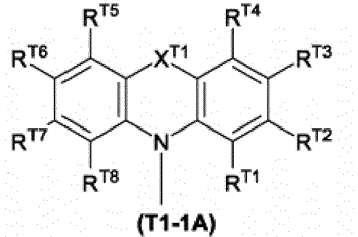 XT1 représente une liaison simple, un atome d'oxygène, un atome de soufre, un groupe représenté par -N(RXT1)- ou un groupe représenté par -C(RXT1')2-, RXT1 et RXT1' représentent chacun indépendamment un atome d'hydrogène, un groupe alkyle, un groupe cycloalkyle, un groupe alcoxy, un groupe cycloalcoxy, un groupe aryle, un groupe aryloxy, un groupe hétérocyclique monovalent, un groupe amino substitué, un atome d'halogène ou un groupe cyano, et les groupes précédents ont éventuellement un substituant, et une pluralité de RXT1' peuvent être identiques ou différents et peuvent être combinés ensemble pour former un cycle avec les atomes auxquels ils sont attachés,RT1, RT2, RT3, RT4, RT5, RT6, RT7 et RT8 représentent chacun indépendamment un atome d'hydrogène, un groupe alkyle, un groupe cycloalkyle, un groupe alcoxy, un groupe cycloalcoxy, un groupe aryle, un groupe aryloxy, un groupe hétérocyclique monovalent, un groupe amino substitué, un atome d'halogène ou un groupe cyano, et les groupes précédents ont éventuellement un substituant.
 - Dispositif électroluminescent selon la revendication 1, dans lequel ledit groupe de réticulation est un groupe de réticulation choisi dans le groupe A du groupe de réticulation :

- Dispositif électroluminescent selon la revendication 2, dans lequel ladite unité constitutionnelle ayant un groupe de réticulation est une unité constitutionnelle représentée par la formule (2) ou la formule (2') :
 nA représente un nombre entier de 0 à 5 et n représente 1 ou 2, et lorsque plusieurs nA sont présents, ils peuvent être identiques ou différents,Ar3 représente un groupe hydrocarbure aromatique ou un groupe hétérocyclique, et les groupes précédents ont éventuellement un substituant,LA représente un groupe alkylène, un groupe cycloalkylène, un groupe arylène, un groupe hétérocyclique divalent, un groupe représenté par -NR'-, un atome d'oxygène ou un atome de soufre, et les groupes précédents ont éventuellement un substituant, R' représente un atome d'hydrogène, un groupe alkyle, un groupe cycloalkyle, un groupe aryle ou un groupe hétérocyclique monovalent, et les groupes précédents ont éventuellement un substituant, et lorsqu'une pluralité de LA sont présents, ils peuvent être identiques ou différents,X représente un groupe de réticulation choisi dans ledit groupe A du groupe de réticulation, et lorsqu'une pluralité de X sont présents, ils peuvent être identiques ou différents,
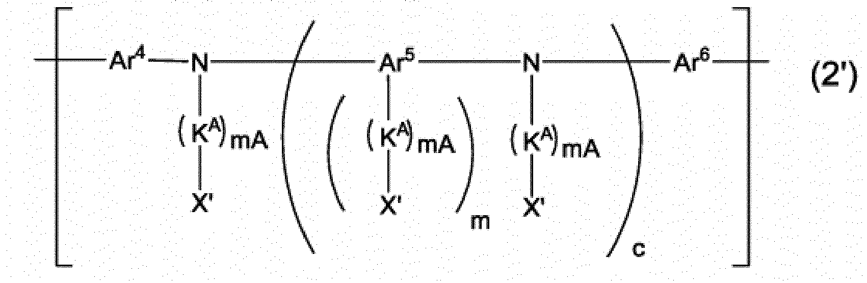 mA représente un nombre entier de 0 à 5, m représente un nombre entier de 1 à 4 et c représente 0 ou 1, et lorsque plusieurs mA sont présents, ils peuvent être identiques ou différents,Ar5 représente un groupe hydrocarbure aromatique, un groupe hétérocyclique ou un groupe dans lequel au moins un cycle hydrocarbure aromatique et au moins un hétérocycle sont liés directement, et les groupes précédents ont éventuellement un substituant,Ar4 et Ar6 représentent chacun indépendamment un groupe arylène ou un groupe hétérocyclique divalent, et les groupes précédents ont éventuellement un substituant,Ar4, Ar5 et Ar6 peuvent être liés directement ou par l'intermédiaire d'un atome d'oxygène ou d'un atome de soufre à des groupes autres que ces groupes liés à un atome d'azote auquel ces groupes sont attachés, pour former un cycle, respectivement,KA représente un groupe alkylène, un groupe cycloalkylène, un groupe arylène, un groupe hétérocyclique divalent, un groupe représenté par -NR'-, un atome d'oxygène ou un atome de soufre, et les groupes précédents ont éventuellement un substituant, R' représente la même signification que celle décrite ci-dessus, et lorsqu'une pluralité de KA sont présents, ils peuvent être identiques ou différents,X' représente un groupe de réticulation choisi parmi ledit groupe A du groupe de réticulation, un atome d'hydrogène, un groupe alkyle, un groupe cycloalkyle, un groupe aryle ou un groupe hétérocyclique monovalent, et les groupes précédents ont éventuellement un substituant, et lorsqu'une pluralité des X' sont présents, ils peuvent être identiques ou différents, et au moins un X' est un groupe de réticulation choisi dans ledit groupe A du groupe de réticulation.
 - Dispositif électroluminescent selon l'une quelconque des revendications 1 à 3, dans lequel au moins un desdits ArT1 est un groupe représenté par la formule (T1-1) :
 XT1 représente la même signification que celle décrite ci-dessus,le cycle RT1 et le cycle RT2 représentent chacun indépendamment un cycle hydrocarbure aromatique ne contenant pas de groupe représenté par -C(=O)- dans le cycle ou un hétérocycle ne contenant pas de groupe représenté par =N-, de groupe représenté par -C(=O)-, de groupe représenté par -S(=O)- et de groupe représenté par -S(=O)2- dans le cycle, et les cycles précédents ont éventuellement un substituant.
 - Dispositif électroluminescent selon la revendication 4, dans lequel ledit groupe représenté par la formule (T1-1) est un groupe représenté par la formule (T1-1A), la formule (T1-1B), la formule (T1-1C) ou la formule (T1-1D) :

 XT1 représente la même signification que celle décrite ci-dessus,XT2 et XT3 représentent chacun indépendamment une liaison simple, un atome d'oxygène, un atome de soufre, un groupe représenté par -N(RXT2)- ou un groupe représenté par -C(RXT2')2-, et RXT2 et RXT2' représentent chacun indépendamment un atome d'hydrogène, un groupe alkyle, un groupe cycloalkyle, un groupe alcoxy, un groupe cycloalcoxy, un groupe aryle, un groupe aryloxy, un groupe hétérocyclique monovalent, un groupe amino substitué, un atome d'halogène ou un groupe cyano, et les groupes précédent ont éventuellement un substituant, et une pluralité de RXT2' peuvent être identiques ou différents et peuvent être combinés ensemble pour former un cycle avec les atomes auxquels ils sont attachés,RT1, RT2, RT3, RT4, RT5, RT6, RT7, RT8, RT9, RT10, RT11 et RT12 représentent chacun indépendamment un atome d'hydrogène, un groupe alkyle, un groupe cycloalkyle, un groupe alcoxy, un groupe cycloalcoxy, un groupe aryle, un groupe aryloxy, un groupe hétérocyclique monovalent, un groupe amino substitué, un atome d'halogène ou un groupe cyano, et les groupes précédents ont éventuellement un substituant.
 - Dispositif électroluminescent selon l'une quelconque des revendications 1 à 5, dans lequel ledit ArT2 est un groupe hétérocyclique monocyclique contenant deux ou plusieurs groupes représentés par =N- dans le cycle et ayant éventuellement un substituant.
- Dispositif électroluminescent selon l'une quelconque des revendications 1 à 6, dans lequel ledit composé de faible poids moléculaire ne contenant pas de métal de transition satisfait à ladite exigence (1) et à ladite exigence (II).
- Dispositif électroluminescent selon l'une quelconque des revendications 1 à 7, dans lequel ledit complexe de métal de transition phosphorescent est un complexe métallique représenté par la formule (1) :
 M représente un atome de ruthénium, un atome de rhodium, un atome de palladium, un atome d'iridium ou un atome de platine,n1 représente un nombre entier de 1 ou plus, n2 représente un nombre entier de 0 ou plus, n1+n2 vaut 3 lorsque M est un atome de ruthénium, un atome de rhodium ou un atome d'iridium, tandis que n1+n2 vaut 2 lorsque M est un atome de palladium ou un atome de platine,E1 et E2 représentent chacun indépendamment un atome de carbone ou un atome d'azote, au moins l'un parmi E1 et E2 est un atome de carbone, et lorsqu'une pluralité de E1 et E2 sont présents, ils peuvent être identiques ou différents à chaque occurrence,le cycle L1 représente un hétérocycle aromatique, et ce cycle a éventuellement un substituant, et lorsqu'une pluralité de substituants sont présents, ils peuvent être combinés ensemble pour former un cycle avec les atomes auxquels ils sont attachés, et lorsqu'une pluralité de cycles L1 sont présents, ils peuvent être identiques ou différents,le cycle L2 représente un cycle hydrocarbure aromatique ou un hétérocycle aromatique, et les cycles précédents ont éventuellement un substituant, et lorsqu'une pluralité de substituants sont présents, ils peuvent être combinés ensemble pour former un cycle avec les atomes auxquels ils sont attachés, et lorsqu'une pluralité de cycles L2 sont présents, ils peuvent être identiques ou différents,le substituant que possède éventuellement le cycle L1 et le substituant que possède éventuellement le cycle L2 peuvent être combinés ensemble pour former un cycle avec les atomes auxquels ils sont attachés,A1-G1-A2 représente un ligand anionique bidenté, A1 et A2 représentent chacun indépendamment un atome de carbone, un atome d'oxygène ou un atome d'azote, et ces atomes peuvent être des atomes constitutifs de cycle, G1 représente une liaison simple ou un groupe atomique constituant un ligand bidenté avec A1 et A2, et lorsqu'une pluralité de A1-G1-A2 sont présents, ils peuvent être identiques ou différents.
 - Dispositif électroluminescent selon la revendication 8, dans lequel ledit complexe métallique représenté par la formule (1) est un complexe métallique représenté par la formule (1-A) :
 M, n1, n2, E1 et A1-G1-A2 représentent la même signification que celle décrite ci-dessus,le cycle L1A représente un cycle pyridine, un cycle diazabenzène, un cycle azanaphthalène, un cycle diazanaphthalène, un cycle triazole ou un cycle diazole, et les cycles précédents ont éventuellement un substituant, et lorsqu'une pluralité de substituants sont présents, ils peuvent être combinés ensemble pour former un cycle avec les atomes auxquels ils sont attachés, et lorsqu'une pluralité de cycles L1A sont présents, ils peuvent être identiques ou différents,E21A, E22A, E23A et E24A représentent chacun indépendamment un atome d'azote ou un atome de carbone, et lorsqu'une pluralité de E21A, E22A, E23A et E24A sont présents, ils peuvent être identiques ou différents à chaque occurrence, et lorsque E21A est un atome d'azote, R21A est absent, et lorsque E22A est un atome d'azote, R22A est absent, et lorsque E23A est un atome d'azote, R23A est absent, et lorsque E24A est un atome d'azote, R24A est absent,R21A, R22A, R23A et R24A représentent chacun indépendamment un atome d'hydrogène, un groupe alkyle, un groupe cycloalkyle, un groupe alcoxy, un groupe cycloalcoxy, un groupe aryle, un groupe aryloxy, un groupe hétérocyclique monovalent, un groupe amino substitué ou un atome d'halogène, et les groupes précédents ont éventuellement un substituant, et lorsqu'une pluralité de R21A, R22A, R23A et R24A sont présents, ils peuvent être identiques ou différents à chaque occurrence, R21A et R22A, R22A et R23A, R23A et R24A, et, le substituant que le cycle L1A a éventuellement et R21A peuvent chacun être combinés ensemble pour former un cycle avec les atomes auxquels ils sont attachés, etle cycle L2A représente un cycle benzène, un cycle pyridine ou un cycle diazabenzène.
 - Dispositif électroluminescent selon la revendication 9, dans lequel ledit complexe métallique représenté par la formule (1-A) est un complexe métallique représenté par la formule (1-B1), la formule (1-B2), la formule (1-B3), la formule (1-B4) ou la formule (1-B5) :


 M, n1, n2, R21A, R22A, R23A, R24A et A1-G1-A2 représentent la même signification que celle décrite ci-dessus,n11 et n21 représentent chacun indépendamment 1 ou 2, n11+n21 vaut 3 lorsque M est un atome de ruthénium, un atome de rhodium ou un atome d'iridium, tandis que n11+n21 vaut 2 lorsque M est un atome de palladium ou un atome de platine,R11B, R12B, R13B, R14B, R15B, R16B, R17B et R18B représentent chacun indépendamment un atome d'hydrogène, un groupe alkyle, un groupe cycloalkyle, un groupe alcoxy, un groupe cycloalcoxy, un groupe aryle, un groupe aryloxy, un groupe hétérocyclique monovalent, un groupe amino substitué ou un atome d'halogène, et les groupes précédents ont éventuellement un substituant, et lorsqu'une pluralité de R11B, R12B, R13B, R14B, R15B, R16B, R17B et R18B sont présents, ils peuvent être identiques ou différents à chaque occurrence,et dans la formule (1-B1), R11B et R12B, R12B et R13B, R13B et R14B, et R11B et R21A peuvent chacun être combinés ensemble pour former un cycle avec les atomes auxquels ils sont attachés, et dans la formule (1-B2), R13B et R14B, R13B et R15B, R15B et R16B, R16B et R17B, R17B et R18B, et R18B et R21A peuvent chacun être combinés ensemble pour former un cycle avec les atomes auxquels ils sont attachés, et dans la formule (1-B3), R11B et R12B, R12B et R13B, R13B et R14B, R11B et R21A, R13B et R15B, R15B et R16B, R16B et R17B, R17B et R18B, et R18B et R21A peuvent être combinés ensemble pour former un cycle avec les atomes auxquels ils sont attachés, et dans la formule (1-B4), R11B et R18B, R14B et R15B, R15B et R16B, R16B et R17B, R17B et R18B, et R11B et R21A peuvent chacun être combinés ensemble pour former un cycle avec les atomes auxquels ils sont attachés, et dans la formule (1-B5), R11B et R12B, R12B et R18B, R15B et R16B, R16B et R17B, R17B et R18B, et R11B et R21A peuvent chacun être combinés ensemble pour former un cycle avec les atomes auxquels ils sont attachés.
 - Dispositif électroluminescent selon l'une quelconque des revendications 1 à 10, dans lequel ladite première couche organique contient en outre au moins un élément choisi dans le groupe constitué par un matériau de transport de trous, un matériau d'injection de trous, un matériau de transport d'électrons, un matériau d'injection d'électrons, un composé fluorescent et un antioxydant.
- Dispositif électroluminescent selon l'une quelconque des revendications 1 à 11, dans lequel ladite deuxième couche organique est une couche disposée entre ladite anode et ladite première couche organique.
Applications Claiming Priority (1)
| Application Number | Priority Date | Filing Date | Title |
|---|---|---|---|
| PCT/JP2017/032043 WO2019049225A1 (fr) | 2017-09-06 | 2017-09-06 | Élément électroluminescent |
Publications (3)
| Publication Number | Publication Date |
|---|---|
| EP3680945A1 EP3680945A1 (fr) | 2020-07-15 |
| EP3680945A4 EP3680945A4 (fr) | 2021-04-21 |
| EP3680945B1 true EP3680945B1 (fr) | 2023-09-06 |
Family
ID=65634977
Family Applications (1)
| Application Number | Title | Priority Date | Filing Date |
|---|---|---|---|
| EP17924326.6A Active EP3680945B1 (fr) | 2017-09-06 | 2017-09-06 | Élément électroluminescent |
Country Status (6)
| Country | Link |
|---|---|
| US (1) | US11515477B2 (fr) |
| EP (1) | EP3680945B1 (fr) |
| JP (1) | JP6566050B2 (fr) |
| KR (1) | KR102361349B1 (fr) |
| CN (1) | CN111052430B (fr) |
| WO (1) | WO2019049225A1 (fr) |
Families Citing this family (6)
| Publication number | Priority date | Publication date | Assignee | Title |
|---|---|---|---|---|
| JP7405676B2 (ja) * | 2020-03-31 | 2023-12-26 | 住友化学株式会社 | 発光素子及び組成物 |
| JP7086258B2 (ja) | 2020-09-24 | 2022-06-17 | 住友化学株式会社 | 発光素子及び組成物 |
| JP7079883B2 (ja) | 2020-09-24 | 2022-06-02 | 住友化学株式会社 | 発光素子及び組成物 |
| JP7015406B1 (ja) | 2020-09-24 | 2022-02-02 | 住友化学株式会社 | 発光素子及び組成物 |
| JP7058792B2 (ja) | 2020-09-24 | 2022-04-22 | 住友化学株式会社 | 発光素子及び組成物 |
| JP7086259B2 (ja) * | 2020-09-24 | 2022-06-17 | 住友化学株式会社 | 発光素子及び組成物 |
Family Cites Families (55)
| Publication number | Priority date | Publication date | Assignee | Title |
|---|---|---|---|---|
| GB0028867D0 (en) | 2000-11-28 | 2001-01-10 | Avecia Ltd | Field effect translators,methods for the manufacture thereof and materials therefor |
| WO2002066552A1 (fr) | 2001-02-20 | 2002-08-29 | Isis Innovation Limited | Dendrimeres contenant du metal |
| GB0311234D0 (en) | 2003-05-16 | 2003-06-18 | Isis Innovation | Organic phosphorescent material and organic optoelectronic device |
| KR101283742B1 (ko) | 2003-11-14 | 2013-07-08 | 스미또모 가가꾸 가부시키가이샤 | 할로겐화 비스디아릴아미노폴리시클릭 방향족 화합물의 중합체 |
| TWI385193B (zh) | 2004-12-07 | 2013-02-11 | Sumitomo Chemical Co | 高分子材料及使用該高分子材料之元件 |
| GB2439030B (en) | 2005-04-18 | 2011-03-02 | Konica Minolta Holdings Inc | Organic electroluminescent device, display and illuminating device |
| US9051344B2 (en) | 2005-05-06 | 2015-06-09 | Universal Display Corporation | Stability OLED materials and devices |
| KR101082258B1 (ko) | 2005-12-01 | 2011-11-09 | 신닛테츠가가쿠 가부시키가이샤 | 유기 전계 발광소자용 화합물 및 유기 전계 발광소자 |
| JP5446079B2 (ja) | 2006-09-25 | 2014-03-19 | 住友化学株式会社 | 高分子化合物及びそれを用いた高分子発光素子 |
| WO2008056746A1 (fr) | 2006-11-09 | 2008-05-15 | Nippon Steel Chemical Co., Ltd. | Composé pour un dispositif électroluminescent organique et dispositif électroluminescent organique |
| JP5262104B2 (ja) | 2006-12-27 | 2013-08-14 | 住友化学株式会社 | 金属錯体、高分子化合物及びこれらを含む素子 |
| JP5499487B2 (ja) | 2008-02-25 | 2014-05-21 | 三菱化学株式会社 | キノリン系化合物、有機電界発光素子用材料、有機電界発光素子用組成物、有機電界発光素子、有機elディスプレイおよび有機el照明 |
| CN102015820A (zh) | 2008-04-25 | 2011-04-13 | 住友化学株式会社 | 具有含氮杂环化合物的残基的高分子化合物 |
| JP5625271B2 (ja) | 2008-07-29 | 2014-11-19 | 住友化学株式会社 | 高分子化合物及びそれを用いた発光素子 |
| JP5720097B2 (ja) | 2009-01-20 | 2015-05-20 | 住友化学株式会社 | メタフェニレン系高分子化合物及びそれを用いた発光素子 |
| JP5624784B2 (ja) | 2009-03-31 | 2014-11-12 | 株式会社半導体エネルギー研究所 | ヘテロ芳香環を有する誘導体、ヘテロ芳香環を有する誘導体を用いた発光素子、発光装置、照明装置、電子機器 |
| JP5560592B2 (ja) | 2009-05-29 | 2014-07-30 | 三菱化学株式会社 | 含窒素複素環化合物、有機電界発光素子材料、有機電界発光素子用組成物、有機電界発光素子、有機elディスプレイ及び有機el照明 |
| DE102009023155A1 (de) | 2009-05-29 | 2010-12-02 | Merck Patent Gmbh | Materialien für organische Elektrolumineszenzvorrichtungen |
| DE102009041414A1 (de) | 2009-09-16 | 2011-03-17 | Merck Patent Gmbh | Metallkomplexe |
| CN102498120B (zh) | 2009-09-16 | 2016-06-08 | 默克专利有限公司 | 用于制造电子器件的制剂 |
| JP5742160B2 (ja) | 2009-10-19 | 2015-07-01 | 住友化学株式会社 | 金属錯体、高分子化合物及びそれを用いた素子 |
| WO2011049241A1 (fr) | 2009-10-22 | 2011-04-28 | 住友化学株式会社 | Élément électroluminescent organique |
| JP5124785B2 (ja) | 2009-12-07 | 2013-01-23 | 新日鉄住金化学株式会社 | 有機発光材料及び有機発光素子 |
| KR101769173B1 (ko) | 2010-01-28 | 2017-08-17 | 스미또모 가가꾸 가부시키가이샤 | 고분자 화합물 및 그것을 이용하여 이루어지는 발광 소자 |
| CN103154005B (zh) * | 2010-10-13 | 2015-08-26 | 新日铁住金化学株式会社 | 含氮芳香族化合物、有机半导体材料及有机电子器件 |
| KR101855548B1 (ko) | 2010-12-21 | 2018-05-04 | 스미또모 가가꾸 가부시키가이샤 | 조성물 및 블록형 공중합체 |
| CN103329619B (zh) | 2011-01-11 | 2015-04-01 | 三菱化学株式会社 | 有机电致发光器件用组合物、有机电致发光器件、显示装置及照明装置 |
| JP5905271B2 (ja) | 2012-01-18 | 2016-04-20 | 住友化学株式会社 | 金属錯体及び該金属錯体を含む発光素子 |
| GB201223369D0 (en) * | 2012-12-24 | 2013-02-06 | Cambridge Display Tech Ltd | Polymer and device |
| US9761820B2 (en) * | 2012-01-31 | 2017-09-12 | Cambridge Display Technology Limited | Polymer |
| EP2832761B1 (fr) | 2012-03-27 | 2020-11-18 | Sumitomo Chemical Company, Limited | Composé polymère et élément d'émission de lumière utilisant celui-ci |
| GB201207866D0 (en) * | 2012-05-04 | 2012-06-20 | Cambridge Display Tech Ltd | Organic light emitting device and method |
| JP5970952B2 (ja) | 2012-05-16 | 2016-08-17 | 住友化学株式会社 | 高分子化合物およびそれを用いた発光素子 |
| WO2013191088A1 (fr) | 2012-06-19 | 2013-12-27 | 住友化学株式会社 | Composé polymère, et élément luminescent mettant en œuvre celui-ci |
| US9166175B2 (en) * | 2012-11-27 | 2015-10-20 | Universal Display Corporation | Organic electroluminescent materials and devices |
| WO2014115743A1 (fr) | 2013-01-23 | 2014-07-31 | 国立大学法人九州大学 | Matériau électroluminescent et élément électroluminescent organique l'utilisant |
| JP6331617B2 (ja) | 2013-04-15 | 2018-05-30 | 住友化学株式会社 | 金属錯体およびそれを用いた発光素子 |
| WO2015020217A1 (fr) | 2013-08-09 | 2015-02-12 | 出光興産株式会社 | Composition pour électroluminescence organique, matériau pour élément électroluminescent organique, solution de matériau pour élément électroluminescent organique, et élément électroluminescent organique |
| US9741934B2 (en) | 2014-03-25 | 2017-08-22 | Sumitomo Chemical Company, Limited | Polymer compound and light emitting device using the same |
| JP2015191978A (ja) | 2014-03-27 | 2015-11-02 | セイコーエプソン株式会社 | 発光装置および電子機器 |
| JP6610536B2 (ja) | 2014-04-09 | 2019-11-27 | 住友化学株式会社 | 発光素子およびそれに用いる組成物 |
| JP5867580B2 (ja) * | 2014-06-04 | 2016-02-24 | 住友化学株式会社 | 発光素子 |
| KR102402729B1 (ko) | 2014-06-18 | 2022-05-26 | 메르크 파텐트 게엠베하 | 유기 전계발광 소자용 재료 |
| DE102014008722B4 (de) | 2014-06-18 | 2024-08-22 | Merck Patent Gmbh | Zusammensetzungen für elektronische Vorrichtungen, Formulierung diese enthaltend, Verwendung der Zusammensetzung, Verwendung der Formulierung sowie organische elektronische Vorrichtung enthaltend die Zusammensetzung |
| JP6651469B2 (ja) | 2014-06-30 | 2020-02-19 | メルク、パテント、ゲゼルシャフト、ミット、ベシュレンクテル、ハフツングMerck Patent GmbH | 金属錯体 |
| WO2016015815A1 (fr) | 2014-07-28 | 2016-02-04 | Merck Patent Gmbh | Complexes métalliques |
| JP6819289B2 (ja) | 2014-08-28 | 2021-01-27 | 住友化学株式会社 | 高分子化合物およびそれを用いた発光素子 |
| US9882151B2 (en) * | 2014-11-14 | 2018-01-30 | Universal Display Corporation | Organic electroluminescent materials and devices |
| US20180022990A1 (en) * | 2015-02-03 | 2018-01-25 | Sumitomo Chemical Company, Limited | Composition and light emitting device using the same |
| JP6524578B2 (ja) * | 2015-03-19 | 2019-06-05 | 日本放送協会 | 化合物および有機エレクトロルミネッセンス素子 |
| US10177318B2 (en) * | 2015-10-29 | 2019-01-08 | Universal Display Corporation | Organic electroluminescent materials and devices |
| US20190214577A1 (en) * | 2015-12-04 | 2019-07-11 | Guangzhou Chinaray Optoelectronic Materials Ltd. | Thermally activated delayed fluorescence material, polymer, mixture, formulation, and organic electronic device |
| CN105418486A (zh) * | 2015-12-25 | 2016-03-23 | 上海天马有机发光显示技术有限公司 | 有机电致发光化合物及其有机光电装置 |
| JP6881430B2 (ja) | 2016-02-25 | 2021-06-02 | 住友化学株式会社 | 発光素子及び該発光素子に用いる高分子化合物 |
| JPWO2017154882A1 (ja) | 2016-03-10 | 2018-03-15 | 住友化学株式会社 | 発光素子 |
-
2017
- 2017-09-06 EP EP17924326.6A patent/EP3680945B1/fr active Active
- 2017-09-06 CN CN201780094604.9A patent/CN111052430B/zh active Active
- 2017-09-06 US US16/642,412 patent/US11515477B2/en active Active
- 2017-09-06 WO PCT/JP2017/032043 patent/WO2019049225A1/fr unknown
- 2017-09-06 JP JP2017564138A patent/JP6566050B2/ja active Active
- 2017-09-06 KR KR1020207009438A patent/KR102361349B1/ko active IP Right Grant
Also Published As
| Publication number | Publication date |
|---|---|
| KR102361349B1 (ko) | 2022-02-14 |
| KR20200051683A (ko) | 2020-05-13 |
| JPWO2019049225A1 (ja) | 2019-11-07 |
| US11515477B2 (en) | 2022-11-29 |
| CN111052430B (zh) | 2023-04-04 |
| WO2019049225A1 (fr) | 2019-03-14 |
| CN111052430A (zh) | 2020-04-21 |
| US20210159416A1 (en) | 2021-05-27 |
| EP3680945A4 (fr) | 2021-04-21 |
| JP6566050B2 (ja) | 2019-08-28 |
| EP3680945A1 (fr) | 2020-07-15 |
Similar Documents
| Publication | Publication Date | Title |
|---|---|---|
| EP3522248B1 (fr) | Élément électroluminescent et composition servant à la fabrication de l'élément électroluminescent | |
| EP3439061B1 (fr) | Élément électroluminescent | |
| US11588119B2 (en) | Light emitting device | |
| EP3680945B1 (fr) | Élément électroluminescent | |
| EP3154101B1 (fr) | Élément électroluminescent | |
| EP3288094B1 (fr) | Élément électroluminescent et composition utilisée dans ledit élément électroluminescent | |
| JP7346015B2 (ja) | 発光素子 | |
| EP3235891A1 (fr) | Composition et élément électroluminescent mettant en uvre cette composition | |
| EP3522247B1 (fr) | Élément électroluminescent | |
| EP3618578A1 (fr) | Composition et élément électroluminescent faisant appel à ladite composition | |
| JP6399243B2 (ja) | 発光素子 | |
| EP3618577A1 (fr) | Composition et élément électroluminescent la comprenant | |
| EP3490019B1 (fr) | Élément électroluminescent | |
| EP3932926B1 (fr) | Élément électroluminescent | |
| EP3618131A1 (fr) | Élément électroluminescent | |
| EP3787052B1 (fr) | Élément électroluminescent | |
| EP4219468A1 (fr) | Élément luminescent et composition | |
| EP3478030A1 (fr) | Élément électroluminescent | |
| JP2019186576A (ja) | 発光素子 | |
| EP4219469A1 (fr) | Élément électroluminescent et composition | |
| EP4219467A1 (fr) | Élément électroluminescent et composition | |
| EP4219654A1 (fr) | Élément électroluminescent et composition |
Legal Events
| Date | Code | Title | Description |
|---|---|---|---|
| STAA | Information on the status of an ep patent application or granted ep patent |
Free format text: STATUS: THE INTERNATIONAL PUBLICATION HAS BEEN MADE |
|
| PUAI | Public reference made under article 153(3) epc to a published international application that has entered the european phase |
Free format text: ORIGINAL CODE: 0009012 |
|
| STAA | Information on the status of an ep patent application or granted ep patent |
Free format text: STATUS: REQUEST FOR EXAMINATION WAS MADE |
|
| 17P | Request for examination filed |
Effective date: 20200219 |
|
| AK | Designated contracting states |
Kind code of ref document: A1 Designated state(s): AL AT BE BG CH CY CZ DE DK EE ES FI FR GB GR HR HU IE IS IT LI LT LU LV MC MK MT NL NO PL PT RO RS SE SI SK SM TR |
|
| AX | Request for extension of the european patent |
Extension state: BA ME |
|
| DAV | Request for validation of the european patent (deleted) | ||
| DAX | Request for extension of the european patent (deleted) | ||
| A4 | Supplementary search report drawn up and despatched |
Effective date: 20210322 |
|
| RIC1 | Information provided on ipc code assigned before grant |
Ipc: H01L 51/00 20060101ALI20210316BHEP Ipc: C09K 11/06 20060101ALI20210316BHEP Ipc: H01L 51/50 20060101AFI20210316BHEP |
|
| REG | Reference to a national code |
Ref country code: DE Ref legal event code: R079 Ref document number: 602017074010 Country of ref document: DE Free format text: PREVIOUS MAIN CLASS: H01L0051500000 Ipc: C09K0011060000 Ref country code: DE Ref legal event code: R079 Free format text: PREVIOUS MAIN CLASS: H01L0051500000 Ipc: C09K0011060000 |
|
| RIC1 | Information provided on ipc code assigned before grant |
Ipc: H10K 101/10 20230101ALI20230412BHEP Ipc: H10K 85/60 20230101ALI20230412BHEP Ipc: H10K 85/30 20230101ALI20230412BHEP Ipc: H10K 85/10 20230101ALI20230412BHEP Ipc: C09K 11/06 20060101AFI20230412BHEP |
|
| GRAP | Despatch of communication of intention to grant a patent |
Free format text: ORIGINAL CODE: EPIDOSNIGR1 |
|
| STAA | Information on the status of an ep patent application or granted ep patent |
Free format text: STATUS: GRANT OF PATENT IS INTENDED |
|
| RIC1 | Information provided on ipc code assigned before grant |
Ipc: H10K 101/40 20230101ALN20230517BHEP Ipc: H10K 50/15 20230101ALN20230517BHEP Ipc: H10K 50/11 20230101ALN20230517BHEP Ipc: H10K 101/10 20230101ALI20230517BHEP Ipc: H10K 85/60 20230101ALI20230517BHEP Ipc: H10K 85/30 20230101ALI20230517BHEP Ipc: H10K 85/10 20230101ALI20230517BHEP Ipc: C09K 11/06 20060101AFI20230517BHEP |
|
| INTG | Intention to grant announced |
Effective date: 20230530 |
|
| GRAS | Grant fee paid |
Free format text: ORIGINAL CODE: EPIDOSNIGR3 |
|
| GRAA | (expected) grant |
Free format text: ORIGINAL CODE: 0009210 |
|
| STAA | Information on the status of an ep patent application or granted ep patent |
Free format text: STATUS: THE PATENT HAS BEEN GRANTED |
|
| AK | Designated contracting states |
Kind code of ref document: B1 Designated state(s): AL AT BE BG CH CY CZ DE DK EE ES FI FR GB GR HR HU IE IS IT LI LT LU LV MC MK MT NL NO PL PT RO RS SE SI SK SM TR |
|
| REG | Reference to a national code |
Ref country code: GB Ref legal event code: FG4D |
|
| REG | Reference to a national code |
Ref country code: CH Ref legal event code: EP |
|
| REG | Reference to a national code |
Ref country code: IE Ref legal event code: FG4D |
|
| REG | Reference to a national code |
Ref country code: DE Ref legal event code: R096 Ref document number: 602017074010 Country of ref document: DE |
|
| PGFP | Annual fee paid to national office [announced via postgrant information from national office to epo] |
Ref country code: DE Payment date: 20230906 Year of fee payment: 7 |
|
| REG | Reference to a national code |
Ref country code: LT Ref legal event code: MG9D |
|
| REG | Reference to a national code |
Ref country code: NL Ref legal event code: MP Effective date: 20230906 |
|
| PG25 | Lapsed in a contracting state [announced via postgrant information from national office to epo] |
Ref country code: GR Free format text: LAPSE BECAUSE OF FAILURE TO SUBMIT A TRANSLATION OF THE DESCRIPTION OR TO PAY THE FEE WITHIN THE PRESCRIBED TIME-LIMIT Effective date: 20231207 |
|
| PG25 | Lapsed in a contracting state [announced via postgrant information from national office to epo] |
Ref country code: SE Free format text: LAPSE BECAUSE OF FAILURE TO SUBMIT A TRANSLATION OF THE DESCRIPTION OR TO PAY THE FEE WITHIN THE PRESCRIBED TIME-LIMIT Effective date: 20230906 Ref country code: RS Free format text: LAPSE BECAUSE OF FAILURE TO SUBMIT A TRANSLATION OF THE DESCRIPTION OR TO PAY THE FEE WITHIN THE PRESCRIBED TIME-LIMIT Effective date: 20230906 Ref country code: NO Free format text: LAPSE BECAUSE OF FAILURE TO SUBMIT A TRANSLATION OF THE DESCRIPTION OR TO PAY THE FEE WITHIN THE PRESCRIBED TIME-LIMIT Effective date: 20231206 Ref country code: LV Free format text: LAPSE BECAUSE OF FAILURE TO SUBMIT A TRANSLATION OF THE DESCRIPTION OR TO PAY THE FEE WITHIN THE PRESCRIBED TIME-LIMIT Effective date: 20230906 Ref country code: LT Free format text: LAPSE BECAUSE OF FAILURE TO SUBMIT A TRANSLATION OF THE DESCRIPTION OR TO PAY THE FEE WITHIN THE PRESCRIBED TIME-LIMIT Effective date: 20230906 Ref country code: HR Free format text: LAPSE BECAUSE OF FAILURE TO SUBMIT A TRANSLATION OF THE DESCRIPTION OR TO PAY THE FEE WITHIN THE PRESCRIBED TIME-LIMIT Effective date: 20230906 Ref country code: GR Free format text: LAPSE BECAUSE OF FAILURE TO SUBMIT A TRANSLATION OF THE DESCRIPTION OR TO PAY THE FEE WITHIN THE PRESCRIBED TIME-LIMIT Effective date: 20231207 Ref country code: FI Free format text: LAPSE BECAUSE OF FAILURE TO SUBMIT A TRANSLATION OF THE DESCRIPTION OR TO PAY THE FEE WITHIN THE PRESCRIBED TIME-LIMIT Effective date: 20230906 |
|
| REG | Reference to a national code |
Ref country code: AT Ref legal event code: MK05 Ref document number: 1608577 Country of ref document: AT Kind code of ref document: T Effective date: 20230906 |
|
| PG25 | Lapsed in a contracting state [announced via postgrant information from national office to epo] |
Ref country code: NL Free format text: LAPSE BECAUSE OF FAILURE TO SUBMIT A TRANSLATION OF THE DESCRIPTION OR TO PAY THE FEE WITHIN THE PRESCRIBED TIME-LIMIT Effective date: 20230906 |
|
| PG25 | Lapsed in a contracting state [announced via postgrant information from national office to epo] |
Ref country code: IS Free format text: LAPSE BECAUSE OF FAILURE TO SUBMIT A TRANSLATION OF THE DESCRIPTION OR TO PAY THE FEE WITHIN THE PRESCRIBED TIME-LIMIT Effective date: 20240106 |
|
| PG25 | Lapsed in a contracting state [announced via postgrant information from national office to epo] |
Ref country code: AT Free format text: LAPSE BECAUSE OF FAILURE TO SUBMIT A TRANSLATION OF THE DESCRIPTION OR TO PAY THE FEE WITHIN THE PRESCRIBED TIME-LIMIT Effective date: 20230906 |
|
| PG25 | Lapsed in a contracting state [announced via postgrant information from national office to epo] |
Ref country code: ES Free format text: LAPSE BECAUSE OF FAILURE TO SUBMIT A TRANSLATION OF THE DESCRIPTION OR TO PAY THE FEE WITHIN THE PRESCRIBED TIME-LIMIT Effective date: 20230906 |
|
| PG25 | Lapsed in a contracting state [announced via postgrant information from national office to epo] |
Ref country code: SM Free format text: LAPSE BECAUSE OF FAILURE TO SUBMIT A TRANSLATION OF THE DESCRIPTION OR TO PAY THE FEE WITHIN THE PRESCRIBED TIME-LIMIT Effective date: 20230906 Ref country code: RO Free format text: LAPSE BECAUSE OF FAILURE TO SUBMIT A TRANSLATION OF THE DESCRIPTION OR TO PAY THE FEE WITHIN THE PRESCRIBED TIME-LIMIT Effective date: 20230906 Ref country code: IS Free format text: LAPSE BECAUSE OF FAILURE TO SUBMIT A TRANSLATION OF THE DESCRIPTION OR TO PAY THE FEE WITHIN THE PRESCRIBED TIME-LIMIT Effective date: 20240106 Ref country code: ES Free format text: LAPSE BECAUSE OF FAILURE TO SUBMIT A TRANSLATION OF THE DESCRIPTION OR TO PAY THE FEE WITHIN THE PRESCRIBED TIME-LIMIT Effective date: 20230906 Ref country code: EE Free format text: LAPSE BECAUSE OF FAILURE TO SUBMIT A TRANSLATION OF THE DESCRIPTION OR TO PAY THE FEE WITHIN THE PRESCRIBED TIME-LIMIT Effective date: 20230906 Ref country code: CZ Free format text: LAPSE BECAUSE OF FAILURE TO SUBMIT A TRANSLATION OF THE DESCRIPTION OR TO PAY THE FEE WITHIN THE PRESCRIBED TIME-LIMIT Effective date: 20230906 Ref country code: AT Free format text: LAPSE BECAUSE OF FAILURE TO SUBMIT A TRANSLATION OF THE DESCRIPTION OR TO PAY THE FEE WITHIN THE PRESCRIBED TIME-LIMIT Effective date: 20230906 Ref country code: SK Free format text: LAPSE BECAUSE OF FAILURE TO SUBMIT A TRANSLATION OF THE DESCRIPTION OR TO PAY THE FEE WITHIN THE PRESCRIBED TIME-LIMIT Effective date: 20230906 Ref country code: PT Free format text: LAPSE BECAUSE OF FAILURE TO SUBMIT A TRANSLATION OF THE DESCRIPTION OR TO PAY THE FEE WITHIN THE PRESCRIBED TIME-LIMIT Effective date: 20240108 |
|
| REG | Reference to a national code |
Ref country code: CH Ref legal event code: PL |
|
| PG25 | Lapsed in a contracting state [announced via postgrant information from national office to epo] |
Ref country code: LU Free format text: LAPSE BECAUSE OF NON-PAYMENT OF DUE FEES Effective date: 20230906 |
|
| REG | Reference to a national code |
Ref country code: BE Ref legal event code: MM Effective date: 20230930 |
|
| PG25 | Lapsed in a contracting state [announced via postgrant information from national office to epo] |
Ref country code: PL Free format text: LAPSE BECAUSE OF FAILURE TO SUBMIT A TRANSLATION OF THE DESCRIPTION OR TO PAY THE FEE WITHIN THE PRESCRIBED TIME-LIMIT Effective date: 20230906 Ref country code: LU Free format text: LAPSE BECAUSE OF NON-PAYMENT OF DUE FEES Effective date: 20230906 Ref country code: IT Free format text: LAPSE BECAUSE OF FAILURE TO SUBMIT A TRANSLATION OF THE DESCRIPTION OR TO PAY THE FEE WITHIN THE PRESCRIBED TIME-LIMIT Effective date: 20230906 |
|
| REG | Reference to a national code |
Ref country code: DE Ref legal event code: R097 Ref document number: 602017074010 Country of ref document: DE |
|
| PG25 | Lapsed in a contracting state [announced via postgrant information from national office to epo] |
Ref country code: MC Free format text: LAPSE BECAUSE OF FAILURE TO SUBMIT A TRANSLATION OF THE DESCRIPTION OR TO PAY THE FEE WITHIN THE PRESCRIBED TIME-LIMIT Effective date: 20230906 |
|
| REG | Reference to a national code |
Ref country code: IE Ref legal event code: MM4A |
|
| PG25 | Lapsed in a contracting state [announced via postgrant information from national office to epo] |
Ref country code: IE Free format text: LAPSE BECAUSE OF NON-PAYMENT OF DUE FEES Effective date: 20230906 |
|
| PG25 | Lapsed in a contracting state [announced via postgrant information from national office to epo] |
Ref country code: DK Free format text: LAPSE BECAUSE OF FAILURE TO SUBMIT A TRANSLATION OF THE DESCRIPTION OR TO PAY THE FEE WITHIN THE PRESCRIBED TIME-LIMIT Effective date: 20230906 |
|
| PLBE | No opposition filed within time limit |
Free format text: ORIGINAL CODE: 0009261 |
|
| STAA | Information on the status of an ep patent application or granted ep patent |
Free format text: STATUS: NO OPPOSITION FILED WITHIN TIME LIMIT |
|
| PG25 | Lapsed in a contracting state [announced via postgrant information from national office to epo] |
Ref country code: CH Free format text: LAPSE BECAUSE OF NON-PAYMENT OF DUE FEES Effective date: 20230930 |
|
| PG25 | Lapsed in a contracting state [announced via postgrant information from national office to epo] |
Ref country code: MC Free format text: LAPSE BECAUSE OF FAILURE TO SUBMIT A TRANSLATION OF THE DESCRIPTION OR TO PAY THE FEE WITHIN THE PRESCRIBED TIME-LIMIT Effective date: 20230906 Ref country code: IE Free format text: LAPSE BECAUSE OF NON-PAYMENT OF DUE FEES Effective date: 20230906 Ref country code: DK Free format text: LAPSE BECAUSE OF FAILURE TO SUBMIT A TRANSLATION OF THE DESCRIPTION OR TO PAY THE FEE WITHIN THE PRESCRIBED TIME-LIMIT Effective date: 20230906 Ref country code: CH Free format text: LAPSE BECAUSE OF NON-PAYMENT OF DUE FEES Effective date: 20230930 Ref country code: SI Free format text: LAPSE BECAUSE OF FAILURE TO SUBMIT A TRANSLATION OF THE DESCRIPTION OR TO PAY THE FEE WITHIN THE PRESCRIBED TIME-LIMIT Effective date: 20230906 |
|
| 26N | No opposition filed |
Effective date: 20240607 |
|
| GBPC | Gb: european patent ceased through non-payment of renewal fee |
Effective date: 20231206 |
|
| PG25 | Lapsed in a contracting state [announced via postgrant information from national office to epo] |
Ref country code: BE Free format text: LAPSE BECAUSE OF NON-PAYMENT OF DUE FEES Effective date: 20230930 |