EP3645182B1 - Method and electronic device for determining the temperature of a metal strip, related control method, computer program, control apparatus and hot rolling installation - Google Patents
Method and electronic device for determining the temperature of a metal strip, related control method, computer program, control apparatus and hot rolling installation Download PDFInfo
- Publication number
- EP3645182B1 EP3645182B1 EP17737645.6A EP17737645A EP3645182B1 EP 3645182 B1 EP3645182 B1 EP 3645182B1 EP 17737645 A EP17737645 A EP 17737645A EP 3645182 B1 EP3645182 B1 EP 3645182B1
- Authority
- EP
- European Patent Office
- Prior art keywords
- cooling
- coolant
- air
- temperature
- strip
- Prior art date
- Legal status (The legal status is an assumption and is not a legal conclusion. Google has not performed a legal analysis and makes no representation as to the accuracy of the status listed.)
- Active
Links
- 238000000034 method Methods 0.000 title claims description 83
- 239000002184 metal Substances 0.000 title claims description 35
- 229910052751 metal Inorganic materials 0.000 title claims description 35
- 238000005098 hot rolling Methods 0.000 title claims description 26
- 238000009434 installation Methods 0.000 title claims description 24
- 238000004590 computer program Methods 0.000 title claims description 4
- 238000001816 cooling Methods 0.000 claims description 179
- 239000002826 coolant Substances 0.000 claims description 111
- 230000004907 flux Effects 0.000 claims description 40
- 229910000831 Steel Inorganic materials 0.000 claims description 13
- 239000010959 steel Substances 0.000 claims description 13
- 230000005855 radiation Effects 0.000 claims description 8
- XLYOFNOQVPJJNP-UHFFFAOYSA-N water Substances O XLYOFNOQVPJJNP-UHFFFAOYSA-N 0.000 claims description 8
- 239000007788 liquid Substances 0.000 claims description 6
- 239000000758 substrate Substances 0.000 claims description 2
- 229910001566 austenite Inorganic materials 0.000 description 9
- 230000000052 comparative effect Effects 0.000 description 8
- 230000009466 transformation Effects 0.000 description 6
- 239000012809 cooling fluid Substances 0.000 description 5
- 229910000859 α-Fe Inorganic materials 0.000 description 5
- 238000005096 rolling process Methods 0.000 description 4
- 238000005070 sampling Methods 0.000 description 4
- OKTJSMMVPCPJKN-UHFFFAOYSA-N Carbon Chemical compound [C] OKTJSMMVPCPJKN-UHFFFAOYSA-N 0.000 description 3
- 229910052799 carbon Inorganic materials 0.000 description 3
- 229910001562 pearlite Inorganic materials 0.000 description 3
- 238000007792 addition Methods 0.000 description 2
- 230000003116 impacting effect Effects 0.000 description 2
- 238000004519 manufacturing process Methods 0.000 description 2
- 239000000203 mixture Substances 0.000 description 2
- 230000006911 nucleation Effects 0.000 description 2
- 238000010899 nucleation Methods 0.000 description 2
- 238000004088 simulation Methods 0.000 description 2
- 239000000126 substance Substances 0.000 description 2
- 230000000930 thermomechanical effect Effects 0.000 description 2
- 238000011144 upstream manufacturing Methods 0.000 description 2
- XEEYBQQBJWHFJM-UHFFFAOYSA-N Iron Chemical group [Fe] XEEYBQQBJWHFJM-UHFFFAOYSA-N 0.000 description 1
- 241001028048 Nicola Species 0.000 description 1
- 230000001133 acceleration Effects 0.000 description 1
- 238000005275 alloying Methods 0.000 description 1
- 229910052782 aluminium Inorganic materials 0.000 description 1
- 230000015556 catabolic process Effects 0.000 description 1
- 229910052804 chromium Inorganic materials 0.000 description 1
- 229910052802 copper Inorganic materials 0.000 description 1
- 230000008878 coupling Effects 0.000 description 1
- 238000010168 coupling process Methods 0.000 description 1
- 238000005859 coupling reaction Methods 0.000 description 1
- 238000000354 decomposition reaction Methods 0.000 description 1
- 238000006731 degradation reaction Methods 0.000 description 1
- 238000009792 diffusion process Methods 0.000 description 1
- 238000006073 displacement reaction Methods 0.000 description 1
- 230000005484 gravity Effects 0.000 description 1
- 230000016507 interphase Effects 0.000 description 1
- 229910052750 molybdenum Inorganic materials 0.000 description 1
- 229910052759 nickel Inorganic materials 0.000 description 1
- 229910001568 polygonal ferrite Inorganic materials 0.000 description 1
- 229910052710 silicon Inorganic materials 0.000 description 1
- 238000000638 solvent extraction Methods 0.000 description 1
- 238000004804 winding Methods 0.000 description 1
Images


Classifications
-
- B—PERFORMING OPERATIONS; TRANSPORTING
- B21—MECHANICAL METAL-WORKING WITHOUT ESSENTIALLY REMOVING MATERIAL; PUNCHING METAL
- B21B—ROLLING OF METAL
- B21B37/00—Control devices or methods specially adapted for metal-rolling mills or the work produced thereby
- B21B37/74—Temperature control, e.g. by cooling or heating the rolls or the product
- B21B37/76—Cooling control on the run-out table
-
- B—PERFORMING OPERATIONS; TRANSPORTING
- B21—MECHANICAL METAL-WORKING WITHOUT ESSENTIALLY REMOVING MATERIAL; PUNCHING METAL
- B21B—ROLLING OF METAL
- B21B45/00—Devices for surface or other treatment of work, specially combined with or arranged in, or specially adapted for use in connection with, metal-rolling mills
- B21B45/02—Devices for surface or other treatment of work, specially combined with or arranged in, or specially adapted for use in connection with, metal-rolling mills for lubricating, cooling, or cleaning
- B21B45/0203—Cooling
- B21B45/0209—Cooling devices, e.g. using gaseous coolants
- B21B45/0215—Cooling devices, e.g. using gaseous coolants using liquid coolants, e.g. for sections, for tubes
- B21B45/0218—Cooling devices, e.g. using gaseous coolants using liquid coolants, e.g. for sections, for tubes for strips, sheets, or plates
-
- C—CHEMISTRY; METALLURGY
- C21—METALLURGY OF IRON
- C21D—MODIFYING THE PHYSICAL STRUCTURE OF FERROUS METALS; GENERAL DEVICES FOR HEAT TREATMENT OF FERROUS OR NON-FERROUS METALS OR ALLOYS; MAKING METAL MALLEABLE, e.g. BY DECARBURISATION OR TEMPERING
- C21D1/00—General methods or devices for heat treatment, e.g. annealing, hardening, quenching or tempering
- C21D1/84—Controlled slow cooling
-
- C—CHEMISTRY; METALLURGY
- C21—METALLURGY OF IRON
- C21D—MODIFYING THE PHYSICAL STRUCTURE OF FERROUS METALS; GENERAL DEVICES FOR HEAT TREATMENT OF FERROUS OR NON-FERROUS METALS OR ALLOYS; MAKING METAL MALLEABLE, e.g. BY DECARBURISATION OR TEMPERING
- C21D11/00—Process control or regulation for heat treatments
- C21D11/005—Process control or regulation for heat treatments for cooling
-
- C—CHEMISTRY; METALLURGY
- C21—METALLURGY OF IRON
- C21D—MODIFYING THE PHYSICAL STRUCTURE OF FERROUS METALS; GENERAL DEVICES FOR HEAT TREATMENT OF FERROUS OR NON-FERROUS METALS OR ALLOYS; MAKING METAL MALLEABLE, e.g. BY DECARBURISATION OR TEMPERING
- C21D9/00—Heat treatment, e.g. annealing, hardening, quenching or tempering, adapted for particular articles; Furnaces therefor
- C21D9/46—Heat treatment, e.g. annealing, hardening, quenching or tempering, adapted for particular articles; Furnaces therefor for sheet metals
-
- G—PHYSICS
- G01—MEASURING; TESTING
- G01K—MEASURING TEMPERATURE; MEASURING QUANTITY OF HEAT; THERMALLY-SENSITIVE ELEMENTS NOT OTHERWISE PROVIDED FOR
- G01K13/00—Thermometers specially adapted for specific purposes
- G01K13/04—Thermometers specially adapted for specific purposes for measuring temperature of moving solid bodies
-
- G—PHYSICS
- G01—MEASURING; TESTING
- G01K—MEASURING TEMPERATURE; MEASURING QUANTITY OF HEAT; THERMALLY-SENSITIVE ELEMENTS NOT OTHERWISE PROVIDED FOR
- G01K17/00—Measuring quantity of heat
- G01K17/06—Measuring quantity of heat conveyed by flowing media, e.g. in heating systems e.g. the quantity of heat in a transporting medium, delivered to or consumed in an expenditure device
- G01K17/08—Measuring quantity of heat conveyed by flowing media, e.g. in heating systems e.g. the quantity of heat in a transporting medium, delivered to or consumed in an expenditure device based upon measurement of temperature difference or of a temperature
-
- C—CHEMISTRY; METALLURGY
- C21—METALLURGY OF IRON
- C21D—MODIFYING THE PHYSICAL STRUCTURE OF FERROUS METALS; GENERAL DEVICES FOR HEAT TREATMENT OF FERROUS OR NON-FERROUS METALS OR ALLOYS; MAKING METAL MALLEABLE, e.g. BY DECARBURISATION OR TEMPERING
- C21D8/00—Modifying the physical properties by deformation combined with, or followed by, heat treatment
- C21D8/02—Modifying the physical properties by deformation combined with, or followed by, heat treatment during manufacturing of plates or strips
- C21D8/0247—Modifying the physical properties by deformation combined with, or followed by, heat treatment during manufacturing of plates or strips characterised by the heat treatment
- C21D8/0263—Modifying the physical properties by deformation combined with, or followed by, heat treatment during manufacturing of plates or strips characterised by the heat treatment following hot rolling
-
- C—CHEMISTRY; METALLURGY
- C21—METALLURGY OF IRON
- C21D—MODIFYING THE PHYSICAL STRUCTURE OF FERROUS METALS; GENERAL DEVICES FOR HEAT TREATMENT OF FERROUS OR NON-FERROUS METALS OR ALLOYS; MAKING METAL MALLEABLE, e.g. BY DECARBURISATION OR TEMPERING
- C21D8/00—Modifying the physical properties by deformation combined with, or followed by, heat treatment
- C21D8/02—Modifying the physical properties by deformation combined with, or followed by, heat treatment during manufacturing of plates or strips
- C21D8/04—Modifying the physical properties by deformation combined with, or followed by, heat treatment during manufacturing of plates or strips to produce plates or strips for deep-drawing
- C21D8/0447—Modifying the physical properties by deformation combined with, or followed by, heat treatment during manufacturing of plates or strips to produce plates or strips for deep-drawing characterised by the heat treatment
- C21D8/0463—Modifying the physical properties by deformation combined with, or followed by, heat treatment during manufacturing of plates or strips to produce plates or strips for deep-drawing characterised by the heat treatment following hot rolling
Definitions
- the present invention relates to a method for determining the temperature of a metal strip, the strip being movable inside a cooling apparatus of a hot rolling installation, the method being implemented by an electronic determination device.
- the invention also relates to a method for controlling a cooling apparatus of a hot rolling installation.
- the invention also relates to a computer program including software instructions which, when executed by a processor, implement such a method.
- the invention also relates to an electronic determination device for determining the temperature of a metal strip, the strip being movable inside a cooling apparatus of a hot rolling installation.
- the invention also relates to a control apparatus for controlling a cooling apparatus and to a hot rolling installation for delivering a metal strip, such as a hot-rolled steel strip.
- Dynamic Run-Out Table Cooling Simulator and Temperature Controllers relate to the control of steel strip cooling after hot rolling. It describes a dynamic run-out table cooling simulator which has been developed to predict temperature property accurately for a wide range of steel chemical compositions and strip dimensions, based on coupling between physically grounded thermal and metallurgical models. It discloses a controller based on model predictions and allowing controlling strip temperature on several positions on the table.
- this article teaches that in order to properly compute the strip thermal path, heat transfer equation has to be solved with account for various phenomena occurring at the strip surfaces. While traveling on the run-out table a strip can be cooled by air; water coming from the headers; and water remaining on the strip after it passes the header.
- the temperature of the hot-rolled steel strip needs to be determined accurately because the equipment upstream of the run-out table, in particular the finishing mill, induce disturbances, such as variations in the strip temperature at the entry of the run-out table or accelerations of the strip. These disturbances result in variations in the cooling of the strip and therefore in its temperature at the time of its winding, and these variations are liable to cause a degradation of the steel strip mechanical properties, leading to a derating of the corresponding steel coil.
- WO 2014/006681 A1 which forms the basis for the preamble of claim 1 and claim 17, also concerns a temperature controller used in a hot rolling line.
- the temperature of the hot-rolled steel strip which is determined from this thermal model is sometimes not sufficiently accurate.
- An object of the invention is therefore to provide a method and a related electronic device for determining the temperature of a metal strip more accurately.
- the subject-matter of the invention is a method for determining the temperature of a metal strip, according to claim 1.
- the method according to the invention provides, regarding the coolant header cooling, a thermal model which is configured for modeling both an impingement cooling corresponding to the cooling of the strip portion by coolant falling under the at least one coolant header and a parallel flow cooling corresponding to the cooling of the strip portion by coolant falling at a given distance from the at least one coolant header.
- the temperature of a metal strip determined with the method according to the invention is therefore more accurate.
- the method according to the invention is more robust. Indeed, its implementation in several distinct plants shows, as it will be explained in further details in the following of the description, that the method according to the invention is performing in several industrial configurations since there is no typical production line in the plants and the plants are almost different from one to another.
- the method is according to any one of claims 2 to 14.
- the subject-matter of the invention is also a method for controlling a cooling apparatus of a hot rolling installation, according to claim 15.
- the subject-matter of the invention is also a computer program according to claim 16.
- the subject-matter of the invention is also an electronic determination device for determining the temperature of a metal strip, according to claim 17.
- the subject-matter of the invention is also a control apparatus for controlling a cooling apparatus of a hot rolling installation, according to claim 18.
- the subject-matter of the invention is also a hot rolling installation for delivering a metal strip, such as a hot-rolled steel strip, according to claim 19.
- the expression "substantially equal to” defines a relation of equality to plus or minus 10%, preferably to plus or minus 5%.
- coolant is meant a cooling fluid.
- the coolant also called cooling fluid, includes for example water, and is preferably water.
- modeling refers to a numerical simulation, such as a simulation run on a computer.
- a hot-rolling installation for delivering a metal strip 1, such as a hot-rolled steel strip, includes a furnace 2 and a rolling mill 3.
- the hot-rolling installation also includes a cooling apparatus 4 for cooling the metal strip 1 and a control apparatus 5 for controlling the cooling apparatus 4.
- the metal strip 1 which, on discharge from the furnace 2 and the rolling mill 3, is moved in a running direction A.
- the running direction A of the strip 1 is substantially horizontal.
- the strip 1 then passes through the cooling apparatus 4, in which the strip is cooled from an initial temperature, which is for example substantially equal to the temperature at the end of the rolling of the strip, down to a final temperature which is for example room temperature, i.e. about 20°C.
- the strip 1 passes through the cooling apparatus 4 in the running direction A at a running speed which is preferably comprised between 1 m/s and 25 m/s.
- the strip 1 is for example a metal plate, such as a hot-rolled steel strip, having a thickness comprised between 1 mm and 30 mm.
- the initial temperature is for example greater than or equal to 600°C, notably greater than or equal to 800°C, or even greater than 1000°C.
- At least one first cooling fluid jet is ejected on a first surface 6 of the strip 1, and at least one second cooling fluid jet is ejected on a second surface 7 of the strip 1.
- the cooling fluid also called coolant, is for example water.
- the strip 1 is running horizontally, so that the first surface 6 of the strip 1 is an upper surface, oriented upwards during the running of the strip 1, and the second surface 7 of the strip 1 is a lower surface, oriented downwards during the running of the strip 1.
- the selected orientations are indicative and are meant with respect to the Figures.
- the terms of « upstream » and « downstream » are meant relatively to the orientation selected in the Figures. These terms are used with respect to the running strip 1.
- the terms of « transverse » « longitudinal » and « vertical » should be understood with respect to the running direction A of the strip 1, which is a longitudinal direction.
- the term of « longitudinal » refers to a direction parallel to the running direction A of the strip 1
- the term of « transverse » refers to a direction orthogonal to the running direction A of the strip 1 and contained in a plane parallel to the first 6 and second 7 surfaces of the strip 1
- the term of « vertical » refers to a direction orthogonal to the running direction A of the strip 1 and orthogonal to the first 6 and second 7 surfaces of the strip 1.
- « length » a dimension of an object in the longitudinal direction will be referred to, by « width » a dimension of an object in a transverse direction, and by « height » a dimension of an object in a vertical direction.
- the cooling apparatus 4 illustrated on Figure 2 comprises at least one top valve 8 and/or at least one bottom valve 9.
- the cooling apparatus 4 comprises preferably several top valves 8 and/or several bottom valves 9, and still preferably several top valves 8 and several bottom valves 9.
- only three top valves 8 and two bottom valves 9 are shown for simplicity of the drawings.
- the cooling apparatus 4 comprises several rollers 10 for supporting the strip 1 and for contributing to the movement of the strip 1 in the moving direction A.
- the control apparatus 5 comprises an electronic determination device 12 for determining the temperature of the metal strip 1, the strip 1 being as described above movable inside the cooling apparatus 4, and an electronic control device 14 for controlling the cooling apparatus 4 according to the temperature determined by the determination device 12.
- the control apparatus 5 includes a processing unit 16 formed for example of a memory 17 and of a processor 18 coupled to the memory 17.
- Each valve 8, 9 is configured for opening or closing the coolant flow 10 in the direction of the metal strip 1.
- Each top valve 8 is disposed above the strip1.
- Each top valve 8 is preferably also disposed above the rollers 10.
- the coolant falls under the valve, i.e. flows downwards in the direction of the metal strip 1.
- Each bottom valve 9 is disposed under the strip1.
- Each bottom valve 9 is preferably also disposed under the rollers 10.
- the coolant is ejected above the valve 9, i.e. upwards in the direction of the metal strip 1. In other words, the coolant is ejected substantially perpendicular to the metal strip 1 from each corresponding valve 8, 9.
- the coolant includes for example water.
- the coolant is preferably water.
- Each valve 8, 9 includes one or several headers, each header including at least one nozzle 20 whereby the coolant flows out.
- Each valve 8, 9 includes preferably several nozzles 20 which are for example dispatched into two rows 22 on both sides of the corresponding valve 8, 9.
- Each row 22 of nozzle(s) 20 is also called header.
- each valve 8, 9 includes two rows 22 of several nozzles 20.
- Each row 22 of nozzle(s) 20 is located at a respective distance D top_i , D bottom_j from a pyrometer 24, where i is an index of a corresponding row 22 of a given top valve 8 and j is an index of a corresponding row 22 of a given bottom valve 9.
- the cooling apparatus 4 comprises for example nine top valves 8 and nine bottom valves 9, the skilled person will understand that the index i for the top rows is comprised between 1 and 18 and similarly that the index j for the bottom rows is comprised between 1 and 18.
- the distances D top_1 , D top_2 , D top_3 , D top_45 D top_5 , etc. are substantially equal to 6 m, 6.9 m, 7.8 m, 8.7 m and respectively 9.6 m.
- the distance ⁇ D top_intra between two rows 22 of a given top valve 8 is substantially equal to 0.9 m and the distance ⁇ D top_inter between two rows 22 of two successive top valves 8 is substantially equal to 0.9 m.
- the distances D bottom_1 , D bottom_2 , D bottom_3 , D bottom_4 , D bottom_5 , etc. are substantially equal to 6 m, 6.3 m, 6.9 m, 7.2 m and respectively 7.8 m.
- the distance ⁇ D bottom_intra between two rows 22 of a given bottom valve 9 is substantially equal to 0.3 m and the distance ⁇ D bottom_inter between two rows 22 of two successive bottom valves 9 is substantially equal to 0.6 m.
- each top valve 8 is at a same height H top relatively from the metal strip 1. In other words, for the top valves 8, all the nozzles 20 are separated from the metal strip 1 by a same distance H top .
- the height H top is for example substantially equal to 2 m.
- the height H top varies from one top valve 8 to the other.
- each bottom valve 9 is at a same height H bottom relatively from the metal strip 1.
- all the nozzles 20 are separated from the metal strip 1 by a same distance H bottom .
- the height H bottom is for example substantially equal to 0.15 m.
- the height H bottom varies from one bottom valve 9 to the other.
- the strip 1 is discretized by the determination device 12 into elementary elements, each elementary element being called portions or also slice.
- the determination device 12 comprises an acquisition module 26 configured for acquiring a measure of a temperature Tk of a portion of the strip 1, also called strip portion, at a current time instant k.
- the determination device 12 comprises an estimation module 28 configured for estimating, at the current time instant k, a heat flux ⁇ (T(k)) extracted from the strip portion inside the cooling apparatus 4 according to a thermal model.
- the determination device 12 comprises a computation module 30 configured for computing a temperature Tk+1 of the strip portion at a next time instant k+1 from the acquired measure of the temperature Tk and the estimated extracted heat flux ⁇ (T(k)).
- the determination device 12 is configured for simulating the cooling of the strip 1, in particular for computing the thermal evolution of the strip 1.
- the electronic control device 14 is configured for controlling the cooling apparatus 4 according to the temperature determined by the determination device 12.
- the electronic control device 14 is configured for determining the flow for each valve 8, 9, and accordingly for determining which valve 8, 9 needs to be turned on or off. For example, based on a given cooling pattern, a given pyrometer position and an aimed temperature, the electronic control device 14 is configured for determining which valves 8, 9 need to be turned on or off in order to compensate for temperature variation and strip speed variation.
- control device 14, the acquisition module 26, the estimation module 28 and the computation module 30 are for example each realized, i.e. implemented, as a software executable by the processor 18.
- the memory 17 of the processing unit 16 is then adapted to store a control software configured to control the cooling apparatus 4 according to the temperature determined by the determination device 12, an acquisition software configured to acquire a measure of a temperature Tk of a strip portion at a current time instant k, an estimation software configured to estimate, at the current time instant k, a heat flux ⁇ (T(k)) extracted from the strip portion inside the cooling apparatus 4 according to the thermal model and a computation software configured to compute a temperature Tk+1 of the strip portion at a next time instant k+1 from the acquired measure of the temperature Tk and the estimated extracted heat flux ⁇ (T(k)).
- the processor 18 of the processing unit 16 is then configured to execute the control software, the acquisition software, the estimation software and the computation software.
- control device 14 the acquisition module 26, the estimation module 28 and the computation module 30 are each in the form of a programmable logic component, such as a Field Programmable Gate Array or FPGA, or in the form of a dedicated integrated circuit, such as an Application Specific integrated Circuit or ASIC.
- a programmable logic component such as a Field Programmable Gate Array or FPGA
- a dedicated integrated circuit such as an Application Specific integrated Circuit or ASIC.
- the thermal model is configured for modeling an air cooling corresponding to the cooling of the strip portion by air radiation and air convection; a coolant header cooling corresponding to the cooling of the strip portion by at least one coolant header, i.e. by at least one row 22 of nozzle(s); and a remaining coolant cooling corresponding to the cooling of the strip portion by coolant remaining on the strip portion after the strip portion passed under the at least one coolant header.
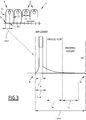
- the thermal model is further configured for modeling both an impingement cooling corresponding to the cooling of the strip portion by coolant impinging from the at least one coolant header, and a parallel flow cooling corresponding to the cooling of the strip portion by coolant falling at a given distance from the at least one coolant header, as shown in Figure 3 .
- the impingement cooling, the parallel flow cooling, the remaining coolant cooling and the air cooling are also called cooling regimes.
- the estimation module 28 is configured to estimate the extracted heat flux ⁇ (T(k)) of the strip portion for at least one surface among the upper surface 6 and the lower surface 7 of the strip 1.
- the estimation module 28 is preferably configured to estimate the extracted heat flux ⁇ (T(k)) for both upper and lower surfaces 6, 7 of the strip 1.
- the estimation module 28 is configured to estimate the extracted heat flux ⁇ (T(k)) only for the upper surface 6 of the strip 1, the cooling regimes taken into account in the thermal model are the impingement cooling, the parallel flow cooling, the remaining coolant cooling and the air cooling for the upper surface 6 of the strip 1.
- the estimation module 28 is configured to estimate the extracted heat flux ⁇ (T(k)) only for the lower surface 7 of the strip 1, the cooling regimes taken into account in the thermal model are the impingement cooling and the air cooling for the lower surface 7 of the strip 1.
- the cooling regimes taken into account in the thermal model are, on one hand, the impingement cooling, the parallel flow cooling, the remaining coolant cooling and the air cooling for the upper surface 6 of the strip 1, and on the other hand, the impingement cooling and the air cooling for the lower surface 7 of the strip 1.
- the computation module 30 is configured for computing the temperature T k+1 of the strip portion at the next time instant k+1 from the acquired measure of the temperature T k and the estimated extracted heat flux ⁇ k .
- L portion is the distance traveled by a given strip portion, or strip slice, between two successive time instants, for example the time instants k, k+1 corresponding to successive positions of the strip portion with successive position indexes N, N+1.
- this distance L portion is equal to the difference between the two positions corresponding to the two successive position indexes N, N+1.
- the impingement zone is centered on the position of current row 22 of nozzle(s) 20 along the running direction A.
- the length L IMP of the impingement zone is for example substantially equal to 3 times an impact diameter D imp along said direction A.
- the impact diameter D imp is the diameter of the coolant flow when impacting the strip 1 to cool it, as shown in Figure 3 .
- the value of the impact diameter D imp is for example comprised between 5 mm and 25 mm.
- the parallel flow zone is the zone immediately after the impingement zone and adjacent to it.
- the length of the parallel flow zone is noted L PF .
- the length of the parallel flow zone L PF is for example comprised between 0.1 m and 2 m.
- the remaining coolant zone is the zone immediately after the parallel flow zone and adjacent to it.
- the length of the remaining coolant zone is noted L RC .
- the length of the remaining coolant zone L RC is for example comprised between 0.1 m and 2 m.
- the air zone is the zone immediately after the remaining coolant zone and adjacent to it. The air zone extends up to the impingement zone for the next row 22 of nozzle(s) 20 of the corresponding top valve 8.
- the impingement zone for the lower surface 7 is also centered on the position of current row 22 of nozzle(s) 20 of the corresponding bottom valve 9 along the running direction A.
- the length L IMP of the impingement zone is for example also substantially equal to 3 times the impact diameter D imp of the nozzle 20 of the corresponding bottom valve 9.
- the air zone is the zone immediately after the impingement zone and adjacent to it.
- the air zone extends up to the impingement zone for the next row 22 of nozzle(s) 20 of the corresponding bottom valve 9.
- the thermal model depends preferably on the impact diameter D imp and on a Reynolds number Re of the coolant.
- Impingement corresponds to the coolant flowing from the header, or row 22 of nozzle(s), and impacting directly the strip 1.
- Impingement corresponds to the coolant flowing from the header, or row 22 of nozzle(s), and impacting directly the strip 1.
- the thermal conductivities ⁇ l , ⁇ v , the saturation temperature T sat , the impact diameter D imp , the Reynolds number of the coolant Re, the Prandtl number of the coolant Pr and the predefined coefficient Q FB have predetermined values known from the estimation module 28.
- the temperature of the coolant T coolant is preferably measured via a temperature sensor, not shown.
- the temperature of the coolant T coolant is a predefined parameter with a predetermined value known from the estimation module 28.
- t is the notation for the time instant when considered in a continuous manner and that the estimation module 28 is configured to discretize the time into successive time instants k, k+1 in order to estimate the extracted heat flux ⁇ (T(k)).
- the thermal model cooling depends preferably on a saturation temperature of the coolant.
- the saturation temperature Tsat and the predefined coefficients Q FB_//1 , Q FB_//2 , Q FB_//3 have predetermined values known from the estimation module 28.
- the thermal model depends preferably on a radiative air cooling flux, on an extracted heat flux previously estimated for the parallel flow cooling and on a length covered by the substrate portion within a remaining coolant section of the cooling apparatus.
- the air cooling is the sum of the air radiation cooling and of the air convection cooling.
- the thermal model depends preferably on a strip portion temperature and on the Stefan constant.
- the Stefan constant a, the emissivity of the strip portion ⁇ and the air temperature T a have predetermined values known from the estimation module 28.
- the thermal model depends preferably on a strip portion temperature and on a heat exchange coefficient H.
- the thermal conductivity of the air ⁇ air the Reynolds number of the air Re air , the Prandtl number of the air Pr air and the air temperature T a have predetermined values known from the estimation module 28.
- step 100 the strip 1 is discretized into the elementary elements, called portions or slices.
- the temperature and metallurgical profile is periodically updated by solving the heat equation, as it will be explained in further detail hereinafter, until it reaches the position of a coiling pyrometer, not shown. The method last until the final portion of the strip 1 reaches the coiling pyrometer position.
- the given portion is displaced by a displacement equal to v x dt, with v a speed of the strip 1 along the running direction A and dt a sampling period, i.e. the time period between two successive time instants k, k+1.
- the strip speed is preferably considered to be constant during the sampling period dt.
- ⁇ pos round v ⁇ dt dx
- a measure of a temperature T k of the strip portion at the current time instant k is acquired by the acquisition module 26 from a corresponding temperature sensor, not shown.
- the determination device 12 calculates, at the next step 120, a phase transformation evolution and new thermo-mechanical properties of the strip portion according to a metallurgical model.
- a metallurgical status of the portion such as a percentage of austenite transformed
- the thermo-mechanical properties of the strip such as the density and/or the specific heat, are also updated.
- the metallurgical model is adapted to describe the decomposition of austenite phase into polygonal ferrite and then further into pearlite with account for steel chemical composition, austenite grain size out of the finishing rolling mill, as well as for the run-out table cooling path.
- This metallurgical model is grounded on the assumption of local equilibrium without partitioning of substitutional atoms.
- the nucleation of ferrite is assumed to occur at austenite grain edges and faces; the driving force for nucleation and the carbon concentration at the austenite/ferrite interface are computed with account for concentrations of alloying additions (Si, Mo, Cr, Ni, Cu, Al).
- Mixed mode of growth of nuclei is adopted where the instantaneous interphase boundary velocity during the austenite/ferrite transformation is calculated as the result of diffusion in austenite of carbon rejected by the transformation and mobility of iron atoms at the austenite/ferrite interface.
- the carbon concentration in the remaining portions of austenite increases until the critical concentration is reached at which pearlite transformation begins.
- the onset of pearlite transformation is described using Hultgren formalism.
- the heat flux ⁇ k extracted from the strip portion inside the cooling apparatus 4 is estimated by the estimation module 28, at the current time instant k, according to the above described thermal model.
- the estimated extracted heat flux corresponds to the time period from the current time instant k to the next time instant k+1.
- the estimation module 28 determines the cooling regime which applies to the upper surface 6 and/or to the lower surface 7 of the strip portion.
- the cooling regime is determined among the impingement cooling which follows for example equation (2), the parallel flow cooling which follows for example equation (3), the remaining coolant cooling which follows for example equations (4) to (8) and the air cooling which follows for example equations (5) to (8).
- the cooling regime is determined among the impingement cooling which follows for example equation (2) and the air cooling which follows for example equations (5) to (8).
- the thermal model is, regarding the coolant header cooling, configured for modeling both the impingement cooling corresponding to the cooling of the strip portion by coolant impinging from the at least one coolant header 22, and a parallel flow cooling corresponding to the cooling of the strip portion by coolant falling at a given distance from the at least one coolant header 22.
- This given distance is for example greater than or equal to L IMP /2, i.e. half of the length L IMP of the impingement zone, when the impingement zone is centered on the position of current row 22 of nozzle(s) 20 along the running direction A.
- the computation module 30 then computes, in the next step 140, the temperature T k+1 of the strip portion at the next time instant k+1 from the acquired measure of the temperature T k and the estimated extracted heat flux ⁇ k . For computing this temperature of the strip portion, the computation module 30 solves a heat equation, such as the equation (1).
- the control device 14 finally controls the cooling apparatus 4 according to the temperature determined by the determination device 12. In particular, the control device 14 determines the flow for each valve 8, 9, and accordingly determines which valve 8, 9 needs to be turned on or off.
- the method and the determination device 12 according to the invention provide, regarding the coolant header cooling, a thermal model which is configured for modeling both the impingement cooling and the parallel flow cooling. Accordingly, the temperature of the metal strip 1 determined with the method according to the invention is more accurate than the temperature of the metal strip 1 determined with the prior art method, as it will presented hereinafter in view of Figures 5 to 10 .
- Figure 5 shows two comparative curves 200, 210 for a first plant including the hot-rolling installation, regarding the percentage of coils that are provided within a defined tolerance on a coiling temperature error, said defined tolerance being indicated on abscissa axis.
- a first curve 200 illustrates the results of the method according to the invention while a second curve 210 shows the results of the prior art method. It will be apparent for the skilled person that the results with the method according to the invention are much better than the ones with the prior art method, since for value of the defined tolerance indicated on abscissa axis, the percentage of provided coils within said defined tolerance are each time better with the method according to the invention than with the prior art method.
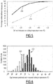
- Figure 6 shows two comparative histograms 250, 260 for the first plant indicating the number of coils that are provided for a respective gap between the predicted and measured coiling temperatures, said gap being indicated on abscissa axis.
- a first histogram 250 illustrates the results of the method according to the invention while a second histogram 260 shows the results of the prior art method. It will be apparent for the skilled person that the results with the method according to the invention are again much better than the ones with the prior art method, since for the low values of the gap indicated on abscissa axis, the number of provided coils are each time higher with the method according to the invention than with the prior art method. Conversely, for high values of the gap, which correspond to a lower accuracy, the number of provided coils are each time higher with the prior art method than with the method according to the invention.
- Figure 7 shows two comparative curves 300, 310 for a second plant including the hot-rolling installation, indicating the percentage of coils that are provided within a defined tolerance on a coiling temperature error.
- a third curve 300 illustrates the results of the method according to the invention while a fourth curve 310 shows the results of the prior art method. It will be apparent for this second plant that the results with the method according to the invention are also much better than the ones with the prior art method.
- Figure 8 shows two comparative histograms 350, 360 for the second plant which indicate the number of coils that are provided for a respective gap between the predicted and measured coiling temperatures.
- a third histogram 350 illustrates the results of the method according to the invention while a fourth histogram 360 shows the results of the prior art method.
- Figure 9 shows, similarly to Figures 5 and 7 , two comparative curves 400, 410 for a third plant including the hot-rolling installation, illustrating the percentage of coils that are provided within a defined tolerance on a coiling temperature error.
- a fifth curve 400 illustrates the results of the method according to the invention while a sixth curve 410 shows the results of the prior art method. Again for this third plant the results with the method according to the invention are better than the ones with the prior art method.
- Figure 10 shows, as for Figures 6 and 8 , two comparative histograms 450, 460 for the third plant with the number of coils provided for a respective gap between the predicted and measured coiling temperatures.
- a fifth histogram 450 illustrates the results of the method according to the invention while a sixth histogram 460 shows the results of the prior art method. The results with the method according to the invention are still better than the ones with the prior art method.
- the skilled person will notice that the results of the method according to the invention are similar from one plant to another, as illustrated with the similar curves 200, 300, 400 and also with the similar histograms 250, 350, 450, while being always better than the results of the prior art method.
- the minor differences between the curves 200, 300, 400 and/or between the histograms 250, 350, 450 from one plant to another are due to differences between input data, in particular to sensors differences from one plant to another.
- the method according to the invention is also more robust. Indeed, its implementation in several distinct plants, as illustrated by the Figures 5 to 10 , shows that the method according to the invention is performing in several industrial configurations since there is no typical production line in the plants and the plants are almost different from one to another.
Landscapes
- Chemical & Material Sciences (AREA)
- Engineering & Computer Science (AREA)
- Mechanical Engineering (AREA)
- Physics & Mathematics (AREA)
- Crystallography & Structural Chemistry (AREA)
- Thermal Sciences (AREA)
- Materials Engineering (AREA)
- Metallurgy (AREA)
- Organic Chemistry (AREA)
- General Physics & Mathematics (AREA)
- Combustion & Propulsion (AREA)
- Control Of Heat Treatment Processes (AREA)
- Control Of Metal Rolling (AREA)
- Heat Treatment Of Strip Materials And Filament Materials (AREA)
Priority Applications (1)
| Application Number | Priority Date | Filing Date | Title |
|---|---|---|---|
| PL17737645T PL3645182T3 (pl) | 2017-06-26 | 2017-06-26 | Sposób i elektroniczne urządzenie do określania temperatury taśmy metalowej, powiązany sposób sterowania, program komputerowy, aparat sterujący oraz instalacja do walcowania na gorąco |
Applications Claiming Priority (1)
| Application Number | Priority Date | Filing Date | Title |
|---|---|---|---|
| PCT/IB2017/053804 WO2019002910A1 (en) | 2017-06-26 | 2017-06-26 | METHOD AND ELECTRONIC DEVICE FOR DETERMINING THE TEMPERATURE OF A METAL STRIP, METHOD OF CONTROLLING THE SAME, COMPUTER PROGRAM, CONTROL APPARATUS AND INSTALLATION OF HOT ROLLING |
Publications (2)
| Publication Number | Publication Date |
|---|---|
| EP3645182A1 EP3645182A1 (en) | 2020-05-06 |
| EP3645182B1 true EP3645182B1 (en) | 2021-08-04 |
Family
ID=59313287
Family Applications (1)
| Application Number | Title | Priority Date | Filing Date |
|---|---|---|---|
| EP17737645.6A Active EP3645182B1 (en) | 2017-06-26 | 2017-06-26 | Method and electronic device for determining the temperature of a metal strip, related control method, computer program, control apparatus and hot rolling installation |
Country Status (14)
| Country | Link |
|---|---|
| US (2) | US20200156129A1 (ko) |
| EP (1) | EP3645182B1 (ko) |
| JP (1) | JP6841976B2 (ko) |
| KR (1) | KR102136042B1 (ko) |
| CN (1) | CN110799276B (ko) |
| AU (1) | AU2017421673B2 (ko) |
| CA (1) | CA3067283C (ko) |
| ES (1) | ES2886455T3 (ko) |
| MX (1) | MX2019015519A (ko) |
| PL (1) | PL3645182T3 (ko) |
| RU (1) | RU2734507C1 (ko) |
| UA (1) | UA125408C2 (ko) |
| WO (1) | WO2019002910A1 (ko) |
| ZA (1) | ZA201908157B (ko) |
Citations (4)
| Publication number | Priority date | Publication date | Assignee | Title |
|---|---|---|---|---|
| WO1998049354A1 (de) | 1997-04-25 | 1998-11-05 | Siemens Aktiengesellschaft | Verfahren und einrichtung zur kühlung von metallen in einem hüttenwerk |
| JP2011200914A (ja) | 2010-03-25 | 2011-10-13 | Jfe Steel Corp | 巻取温度制御装置及び巻取温度制御方法 |
| JP2012000663A (ja) | 2010-06-21 | 2012-01-05 | Kobe Steel Ltd | 圧延材の冷却制御方法、及びこの冷却制御方法が適用された連続圧延機 |
| WO2014006681A1 (ja) | 2012-07-02 | 2014-01-09 | 東芝三菱電機産業システム株式会社 | 温度制御装置 |
Family Cites Families (23)
| Publication number | Priority date | Publication date | Assignee | Title |
|---|---|---|---|---|
| SU759165A1 (ru) * | 1978-09-18 | 1980-08-30 | Предприятие П/Я А-7697 | Устройство дл регулировани температуры полосы на выходном рольганге непрерывного стана гор чей прокатки |
| FR2517039A1 (fr) * | 1981-11-26 | 1983-05-27 | Usinor | Procede et installation pour effectuer le refroidissement controle de toles |
| JP2954485B2 (ja) * | 1994-02-07 | 1999-09-27 | 新日本製鐵株式会社 | 熱延鋼帯の捲取温度制御方法 |
| JP3480366B2 (ja) * | 1999-05-07 | 2003-12-15 | 住友金属工業株式会社 | 熱延鋼板の巻取温度制御方法 |
| DE19963186B4 (de) * | 1999-12-27 | 2005-04-14 | Siemens Ag | Verfahren zur Steuerung und/oder Regelung der Kühlstrecke einer Warmbandstrasse zum Walzen von Metallband und zugehörige Vorrichtung |
| JP2001234251A (ja) * | 2000-02-28 | 2001-08-28 | Kawasaki Steel Corp | 連続帯板の板幅方向温度制御方法 |
| JP4958761B2 (ja) * | 2007-12-21 | 2012-06-20 | 株式会社日立製作所 | 巻取り温度制御装置および制御方法 |
| EP2361699A1 (de) * | 2010-02-26 | 2011-08-31 | Siemens Aktiengesellschaft | Verfahren zur Kühlung eines Blechs mittels einer Kühlstrecke, Kühlstrecke und Steuer- und/oder Regeleinrichtung für eine Kühlstrecke |
| US9056342B2 (en) * | 2010-04-09 | 2015-06-16 | Toshiba Mitsubishi-Electric Industrial Systems Corporation | Rolled material cooling control apparatus, rolled material cooling control method, and rolled material cooling control program |
| JP5679914B2 (ja) * | 2011-06-15 | 2015-03-04 | 株式会社神戸製鋼所 | 鋼板の温度予測方法 |
| CN102371283B (zh) * | 2011-10-14 | 2013-08-28 | 东北大学 | 用于改善中厚板轧后超快速冷却均匀性的方法 |
| JP5948967B2 (ja) * | 2012-03-01 | 2016-07-06 | Jfeスチール株式会社 | 熱間圧延における金属板の温度予測方法、冷却制御方法及び冷却制御装置 |
| JP5811046B2 (ja) * | 2012-06-20 | 2015-11-11 | 新日鐵住金株式会社 | 熱延鋼板の温度むら予測方法、平坦度制御方法、温度むら制御方法、及び、製造方法 |
| JP6136544B2 (ja) * | 2013-05-02 | 2017-05-31 | 新日鐵住金株式会社 | 仕上圧延前温度算出方法、仕上圧延前温度制御方法、仕上圧延前温度算出装置および仕上圧延前温度制御装置 |
| JP2015080788A (ja) * | 2013-10-21 | 2015-04-27 | 東芝三菱電機産業システム株式会社 | 圧延材の温度制御装置 |
| CN103611734B (zh) * | 2013-11-25 | 2015-11-18 | 华中科技大学 | 一种层流冷却温度控制方法及系统 |
| CN105522004B (zh) * | 2014-09-30 | 2017-09-08 | 上海梅山钢铁股份有限公司 | 一种热轧带钢船形卷取温度精度控制及统计方法 |
| CN105652913B (zh) * | 2014-11-14 | 2018-03-09 | 宝山钢铁股份有限公司 | 钢板感应加热过程边部温度控制方法和控制装置 |
| JP6558060B2 (ja) * | 2015-05-07 | 2019-08-14 | 日本製鉄株式会社 | 厚鋼板の冷却制御方法、冷却制御装置、製造方法、および、製造装置 |
| JP6433373B2 (ja) * | 2015-05-11 | 2018-12-05 | 株式会社神戸製鋼所 | 熱伝達率モデルを構成するパラメータの推定方法 |
| JP6645037B2 (ja) * | 2015-06-16 | 2020-02-12 | 日本製鉄株式会社 | 厚鋼板の冷却制御方法、冷却制御装置、製造方法、および、製造装置 |
| CN105327949B (zh) * | 2015-11-25 | 2017-08-22 | 北京金自天正智能控制股份有限公司 | 一种热轧带钢卷取温度的流量控制方法 |
| CN106311778A (zh) * | 2016-08-30 | 2017-01-11 | 北京首钢自动化信息技术有限公司 | 一种在线自动保养热轧层流冷却集管的方法 |
-
2017
- 2017-06-26 PL PL17737645T patent/PL3645182T3/pl unknown
- 2017-06-26 US US16/626,173 patent/US20200156129A1/en active Pending
- 2017-06-26 AU AU2017421673A patent/AU2017421673B2/en active Active
- 2017-06-26 RU RU2019143165A patent/RU2734507C1/ru active
- 2017-06-26 EP EP17737645.6A patent/EP3645182B1/en active Active
- 2017-06-26 WO PCT/IB2017/053804 patent/WO2019002910A1/en unknown
- 2017-06-26 CA CA3067283A patent/CA3067283C/en active Active
- 2017-06-26 JP JP2020520842A patent/JP6841976B2/ja active Active
- 2017-06-26 ES ES17737645T patent/ES2886455T3/es active Active
- 2017-06-26 UA UAA201912240A patent/UA125408C2/uk unknown
- 2017-06-26 KR KR1020197037407A patent/KR102136042B1/ko active IP Right Grant
- 2017-06-26 MX MX2019015519A patent/MX2019015519A/es unknown
- 2017-06-26 CN CN201780092481.5A patent/CN110799276B/zh active Active
-
2019
- 2019-12-09 ZA ZA2019/08157A patent/ZA201908157B/en unknown
-
2024
- 2024-01-23 US US18/420,054 patent/US20240157421A1/en active Pending
Patent Citations (4)
| Publication number | Priority date | Publication date | Assignee | Title |
|---|---|---|---|---|
| WO1998049354A1 (de) | 1997-04-25 | 1998-11-05 | Siemens Aktiengesellschaft | Verfahren und einrichtung zur kühlung von metallen in einem hüttenwerk |
| JP2011200914A (ja) | 2010-03-25 | 2011-10-13 | Jfe Steel Corp | 巻取温度制御装置及び巻取温度制御方法 |
| JP2012000663A (ja) | 2010-06-21 | 2012-01-05 | Kobe Steel Ltd | 圧延材の冷却制御方法、及びこの冷却制御方法が適用された連続圧延機 |
| WO2014006681A1 (ja) | 2012-07-02 | 2014-01-09 | 東芝三菱電機産業システム株式会社 | 温度制御装置 |
Non-Patent Citations (6)
| Title |
|---|
| BISWAS SAROJ K, CHEN SHIH-J, SATYANARAYANA AND A: "Optimal temperature tracking for accelerated cooling processes in hot rolling of steel", DYNAMICS AND CONTROL, vol. 7, 1997, pages 327 - 340, XP055924001 |
| FRANCO, GOEFFREY: "Boiling heat transfer during cooling of a hot moving steel plate by multiple top jets", PHD-THESIS, December 2008 (2008-12-01), pages 1 - 102, XP055924003 |
| PARK, II SEOUK: "Effects of Cooling Water Supply Nozzle Array on Cool- ing Performance of Run Out Table in Hot Rolling Process", ISIJ INTERNA- TIONAL, vol. 53, no. 1, 2013, pages 71 - 75, XP055924006 |
| PARK, II SEOUK: "Numerical Analysis for Film Boiling Heat Transfer of a Moving Hot Steel Plate", ISIJ INTERNATIONAL, vol. 51, no. 5, 2011, pages 743 - 747, XP055923974 |
| TIMM W., WEINZIERL K., LEIPERTZ A.: "Modellierung des Wärmeübergangs beim Strahl- sieden auf stark überhitzten Oberflächen", CHEMIEINGENIEURTECHNIK, vol. 75, no. 12, 2003, pages 1832 - 1835, XP071059242 |
| XU, FUCHANG: "Finite element simulation of water cooling process of steel strips on runout table", PHD-THESIS, March 2006 (2006-03-01), pages 1 - 240, XP055923972 |
Also Published As
| Publication number | Publication date |
|---|---|
| JP6841976B2 (ja) | 2021-03-10 |
| CA3067283C (en) | 2022-03-22 |
| CN110799276B (zh) | 2021-03-19 |
| KR20200003218A (ko) | 2020-01-08 |
| AU2017421673B2 (en) | 2020-10-01 |
| WO2019002910A1 (en) | 2019-01-03 |
| US20200156129A1 (en) | 2020-05-21 |
| UA125408C2 (uk) | 2022-03-02 |
| CA3067283A1 (en) | 2019-01-03 |
| EP3645182A1 (en) | 2020-05-06 |
| CN110799276A (zh) | 2020-02-14 |
| ZA201908157B (en) | 2021-06-30 |
| AU2017421673A1 (en) | 2020-01-02 |
| US20240157421A1 (en) | 2024-05-16 |
| PL3645182T3 (pl) | 2022-01-03 |
| KR102136042B1 (ko) | 2020-07-21 |
| ES2886455T3 (es) | 2021-12-20 |
| BR112019027307A2 (pt) | 2020-07-21 |
| JP2020525302A (ja) | 2020-08-27 |
| RU2734507C1 (ru) | 2020-10-19 |
| MX2019015519A (es) | 2020-02-13 |
Similar Documents
| Publication | Publication Date | Title |
|---|---|---|
| EP2070608B1 (en) | Method of cooling control, cooling control unit and cooling water quantity computing unit | |
| KR101903298B1 (ko) | 연속 주조기의 2차 냉각 제어 방법 및 2차 냉각 제어 장치 | |
| US10710133B2 (en) | Temperature calculation method, temperature calculation apparatus, heating control method, and heating control apparatus | |
| JP5776642B2 (ja) | 連続鋳造機の二次冷却方法及び二次冷却装置 | |
| JP5565200B2 (ja) | 熱間圧延における仕上温度制御装置 | |
| JP5811046B2 (ja) | 熱延鋼板の温度むら予測方法、平坦度制御方法、温度むら制御方法、及び、製造方法 | |
| JP5757296B2 (ja) | 連続鋳造機の2次冷却制御方法及び2次冷却制御装置 | |
| Camporredondo S et al. | Analysis of thin-slab casting by the compact-strip process: Part I. Heat extraction and solidification | |
| EP3645182B1 (en) | Method and electronic device for determining the temperature of a metal strip, related control method, computer program, control apparatus and hot rolling installation | |
| JP6558060B2 (ja) | 厚鋼板の冷却制御方法、冷却制御装置、製造方法、および、製造装置 | |
| JP5493993B2 (ja) | 厚鋼板の冷却制御装置、冷却制御方法、及び、製造方法 | |
| JP3423500B2 (ja) | 熱延鋼板の巻取温度制御装置及びその巻取温度制御方法 | |
| CN105537284A (zh) | 一种热连轧精轧入口温度预报方法 | |
| JPH08103809A (ja) | 熱間圧延における鋼板の冷却制御方法 | |
| Muvunzi et al. | Heat transfer in a hot stamping process: a review | |
| Vidoni et al. | Profile strip casting with inline hot rolling: Numerical simulations for the process chain design | |
| JP6451331B2 (ja) | 熱伝達率の同定方法 | |
| JP6485196B2 (ja) | 厚鋼板の冷却制御方法、冷却制御装置、製造方法、および、製造装置 | |
| JP6781409B2 (ja) | 温度推定方法および温度推定装置 | |
| BR112019027307B1 (pt) | Método para determinar a temperatura de uma tira de metal, método para controlar um aparelho de resfriamento, meio de armazenamento legível por computador, dispositivo eletrônico de determinação, aparelho de controle e instalação de laminação a quente | |
| Nobari | Mechanistic jet impingement model for cooling of hot steel plates | |
| JP5757217B2 (ja) | 鋼板の冷却制御方法、鋼板の製造装置 | |
| JPH04274812A (ja) | 熱間圧延における鋼帯の冷却制御方法 | |
| Bierbrauer et al. | Application of the Eulerian-Lagrangian Method to Water-Jet Cooling of a Hot Moving Strip | |
| POLKONTINUIRNO et al. | A NONDESTRUCTIVE EXPERIMENTAL DETERMINATION OF THE HEAT FLUX DURING COOLING OF DIRECT-CHILL CAST ALUMINUM ALLOY BILLETS |
Legal Events
| Date | Code | Title | Description |
|---|---|---|---|
| STAA | Information on the status of an ep patent application or granted ep patent |
Free format text: STATUS: UNKNOWN |
|
| STAA | Information on the status of an ep patent application or granted ep patent |
Free format text: STATUS: THE INTERNATIONAL PUBLICATION HAS BEEN MADE |
|
| PUAI | Public reference made under article 153(3) epc to a published international application that has entered the european phase |
Free format text: ORIGINAL CODE: 0009012 |
|
| STAA | Information on the status of an ep patent application or granted ep patent |
Free format text: STATUS: REQUEST FOR EXAMINATION WAS MADE |
|
| 17P | Request for examination filed |
Effective date: 20191224 |
|
| AK | Designated contracting states |
Kind code of ref document: A1 Designated state(s): AL AT BE BG CH CY CZ DE DK EE ES FI FR GB GR HR HU IE IS IT LI LT LU LV MC MK MT NL NO PL PT RO RS SE SI SK SM TR |
|
| AX | Request for extension of the european patent |
Extension state: BA ME |
|
| DAX | Request for extension of the european patent (deleted) | ||
| RAV | Requested validation state of the european patent: fee paid |
Extension state: MA Effective date: 20191224 |
|
| GRAP | Despatch of communication of intention to grant a patent |
Free format text: ORIGINAL CODE: EPIDOSNIGR1 |
|
| STAA | Information on the status of an ep patent application or granted ep patent |
Free format text: STATUS: GRANT OF PATENT IS INTENDED |
|
| INTG | Intention to grant announced |
Effective date: 20210316 |
|
| GRAS | Grant fee paid |
Free format text: ORIGINAL CODE: EPIDOSNIGR3 |
|
| GRAA | (expected) grant |
Free format text: ORIGINAL CODE: 0009210 |
|
| STAA | Information on the status of an ep patent application or granted ep patent |
Free format text: STATUS: THE PATENT HAS BEEN GRANTED |
|
| AK | Designated contracting states |
Kind code of ref document: B1 Designated state(s): AL AT BE BG CH CY CZ DE DK EE ES FI FR GB GR HR HU IE IS IT LI LT LU LV MC MK MT NL NO PL PT RO RS SE SI SK SM TR |
|
| REG | Reference to a national code |
Ref country code: GB Ref legal event code: FG4D |
|
| REG | Reference to a national code |
Ref country code: AT Ref legal event code: REF Ref document number: 1416441 Country of ref document: AT Kind code of ref document: T Effective date: 20210815 |
|
| REG | Reference to a national code |
Ref country code: CH Ref legal event code: EP |
|
| REG | Reference to a national code |
Ref country code: DE Ref legal event code: R096 Ref document number: 602017043363 Country of ref document: DE |
|
| REG | Reference to a national code |
Ref country code: IE Ref legal event code: FG4D |
|
| REG | Reference to a national code |
Ref country code: SE Ref legal event code: TRGR |
|
| REG | Reference to a national code |
Ref country code: RO Ref legal event code: EPE |
|
| REG | Reference to a national code |
Ref country code: NL Ref legal event code: FP |
|
| REG | Reference to a national code |
Ref country code: LT Ref legal event code: MG9D |
|
| REG | Reference to a national code |
Ref country code: ES Ref legal event code: FG2A Ref document number: 2886455 Country of ref document: ES Kind code of ref document: T3 Effective date: 20211220 |
|
| REG | Reference to a national code |
Ref country code: SK Ref legal event code: T3 Ref document number: E 38492 Country of ref document: SK |
|
| PG25 | Lapsed in a contracting state [announced via postgrant information from national office to epo] |
Ref country code: FI Free format text: LAPSE BECAUSE OF FAILURE TO SUBMIT A TRANSLATION OF THE DESCRIPTION OR TO PAY THE FEE WITHIN THE PRESCRIBED TIME-LIMIT Effective date: 20210804 Ref country code: PT Free format text: LAPSE BECAUSE OF FAILURE TO SUBMIT A TRANSLATION OF THE DESCRIPTION OR TO PAY THE FEE WITHIN THE PRESCRIBED TIME-LIMIT Effective date: 20211206 Ref country code: NO Free format text: LAPSE BECAUSE OF FAILURE TO SUBMIT A TRANSLATION OF THE DESCRIPTION OR TO PAY THE FEE WITHIN THE PRESCRIBED TIME-LIMIT Effective date: 20211104 Ref country code: LT Free format text: LAPSE BECAUSE OF FAILURE TO SUBMIT A TRANSLATION OF THE DESCRIPTION OR TO PAY THE FEE WITHIN THE PRESCRIBED TIME-LIMIT Effective date: 20210804 Ref country code: BG Free format text: LAPSE BECAUSE OF FAILURE TO SUBMIT A TRANSLATION OF THE DESCRIPTION OR TO PAY THE FEE WITHIN THE PRESCRIBED TIME-LIMIT Effective date: 20211104 Ref country code: HR Free format text: LAPSE BECAUSE OF FAILURE TO SUBMIT A TRANSLATION OF THE DESCRIPTION OR TO PAY THE FEE WITHIN THE PRESCRIBED TIME-LIMIT Effective date: 20210804 Ref country code: RS Free format text: LAPSE BECAUSE OF FAILURE TO SUBMIT A TRANSLATION OF THE DESCRIPTION OR TO PAY THE FEE WITHIN THE PRESCRIBED TIME-LIMIT Effective date: 20210804 |
|
| PG25 | Lapsed in a contracting state [announced via postgrant information from national office to epo] |
Ref country code: LV Free format text: LAPSE BECAUSE OF FAILURE TO SUBMIT A TRANSLATION OF THE DESCRIPTION OR TO PAY THE FEE WITHIN THE PRESCRIBED TIME-LIMIT Effective date: 20210804 Ref country code: GR Free format text: LAPSE BECAUSE OF FAILURE TO SUBMIT A TRANSLATION OF THE DESCRIPTION OR TO PAY THE FEE WITHIN THE PRESCRIBED TIME-LIMIT Effective date: 20211105 |
|
| PG25 | Lapsed in a contracting state [announced via postgrant information from national office to epo] |
Ref country code: DK Free format text: LAPSE BECAUSE OF FAILURE TO SUBMIT A TRANSLATION OF THE DESCRIPTION OR TO PAY THE FEE WITHIN THE PRESCRIBED TIME-LIMIT Effective date: 20210804 |
|
| REG | Reference to a national code |
Ref country code: DE Ref legal event code: R026 Ref document number: 602017043363 Country of ref document: DE |
|
| PLBI | Opposition filed |
Free format text: ORIGINAL CODE: 0009260 |
|
| PLAX | Notice of opposition and request to file observation + time limit sent |
Free format text: ORIGINAL CODE: EPIDOSNOBS2 |
|
| PG25 | Lapsed in a contracting state [announced via postgrant information from national office to epo] |
Ref country code: SM Free format text: LAPSE BECAUSE OF FAILURE TO SUBMIT A TRANSLATION OF THE DESCRIPTION OR TO PAY THE FEE WITHIN THE PRESCRIBED TIME-LIMIT Effective date: 20210804 Ref country code: EE Free format text: LAPSE BECAUSE OF FAILURE TO SUBMIT A TRANSLATION OF THE DESCRIPTION OR TO PAY THE FEE WITHIN THE PRESCRIBED TIME-LIMIT Effective date: 20210804 Ref country code: AL Free format text: LAPSE BECAUSE OF FAILURE TO SUBMIT A TRANSLATION OF THE DESCRIPTION OR TO PAY THE FEE WITHIN THE PRESCRIBED TIME-LIMIT Effective date: 20210804 |
|
| 26 | Opposition filed |
Opponent name: SMS GROUP GMBH Effective date: 20220504 |
|
| PG25 | Lapsed in a contracting state [announced via postgrant information from national office to epo] |
Ref country code: SI Free format text: LAPSE BECAUSE OF FAILURE TO SUBMIT A TRANSLATION OF THE DESCRIPTION OR TO PAY THE FEE WITHIN THE PRESCRIBED TIME-LIMIT Effective date: 20210804 |
|
| PLBB | Reply of patent proprietor to notice(s) of opposition received |
Free format text: ORIGINAL CODE: EPIDOSNOBS3 |
|
| PG25 | Lapsed in a contracting state [announced via postgrant information from national office to epo] |
Ref country code: MC Free format text: LAPSE BECAUSE OF FAILURE TO SUBMIT A TRANSLATION OF THE DESCRIPTION OR TO PAY THE FEE WITHIN THE PRESCRIBED TIME-LIMIT Effective date: 20210804 |
|
| REG | Reference to a national code |
Ref country code: CH Ref legal event code: PL |
|
| PG25 | Lapsed in a contracting state [announced via postgrant information from national office to epo] |
Ref country code: LU Free format text: LAPSE BECAUSE OF NON-PAYMENT OF DUE FEES Effective date: 20220626 Ref country code: LI Free format text: LAPSE BECAUSE OF NON-PAYMENT OF DUE FEES Effective date: 20220630 Ref country code: IE Free format text: LAPSE BECAUSE OF NON-PAYMENT OF DUE FEES Effective date: 20220626 Ref country code: CH Free format text: LAPSE BECAUSE OF NON-PAYMENT OF DUE FEES Effective date: 20220630 |
|
| P01 | Opt-out of the competence of the unified patent court (upc) registered |
Effective date: 20230427 |
|
| PGFP | Annual fee paid to national office [announced via postgrant information from national office to epo] |
Ref country code: RO Payment date: 20230606 Year of fee payment: 7 Ref country code: NL Payment date: 20230523 Year of fee payment: 7 Ref country code: IT Payment date: 20230523 Year of fee payment: 7 Ref country code: FR Payment date: 20230523 Year of fee payment: 7 Ref country code: DE Payment date: 20230523 Year of fee payment: 7 Ref country code: CZ Payment date: 20230526 Year of fee payment: 7 |
|
| PGFP | Annual fee paid to national office [announced via postgrant information from national office to epo] |
Ref country code: TR Payment date: 20230529 Year of fee payment: 7 Ref country code: SK Payment date: 20230529 Year of fee payment: 7 Ref country code: SE Payment date: 20230523 Year of fee payment: 7 Ref country code: PL Payment date: 20230524 Year of fee payment: 7 Ref country code: AT Payment date: 20230525 Year of fee payment: 7 |
|
| PGFP | Annual fee paid to national office [announced via postgrant information from national office to epo] |
Ref country code: BE Payment date: 20230523 Year of fee payment: 7 |
|
| PGFP | Annual fee paid to national office [announced via postgrant information from national office to epo] |
Ref country code: GB Payment date: 20230524 Year of fee payment: 7 Ref country code: ES Payment date: 20230703 Year of fee payment: 7 |
|
| REG | Reference to a national code |
Ref country code: DE Ref legal event code: R100 Ref document number: 602017043363 Country of ref document: DE |
|
| PLCK | Communication despatched that opposition was rejected |
Free format text: ORIGINAL CODE: EPIDOSNREJ1 |
|
| PLBN | Opposition rejected |
Free format text: ORIGINAL CODE: 0009273 |
|
| STAA | Information on the status of an ep patent application or granted ep patent |
Free format text: STATUS: OPPOSITION REJECTED |
|
| PG25 | Lapsed in a contracting state [announced via postgrant information from national office to epo] |
Ref country code: MK Free format text: LAPSE BECAUSE OF FAILURE TO SUBMIT A TRANSLATION OF THE DESCRIPTION OR TO PAY THE FEE WITHIN THE PRESCRIBED TIME-LIMIT Effective date: 20210804 Ref country code: CY Free format text: LAPSE BECAUSE OF FAILURE TO SUBMIT A TRANSLATION OF THE DESCRIPTION OR TO PAY THE FEE WITHIN THE PRESCRIBED TIME-LIMIT Effective date: 20210804 |
|
| REG | Reference to a national code |
Ref country code: CH Ref legal event code: PK Free format text: DIE PUBLIKATION VOM 17.04.2024 WURDE AM 24.04.2024 IRRTUEMLICHERWEISE ERNEUT PUBLIZIERT. LA PUBLICATION DU 17.04.2024 A ETE REPUBLIEE PAR ERREUR LE 24.04.2024. LA PUBBLICAZIONE DEL 17.04.2024 E STATA ERRONEAMENTE RIPUBBLICATA IL 24.04.2024. |
|
| VS25 | Lapsed in a validation state [announced via postgrant information from nat. office to epo] |
Ref country code: MA Free format text: LAPSE BECAUSE OF FAILURE TO SUBMIT A TRANSLATION OF THE DESCRIPTION OR TO PAY THE FEE WITHIN THE PRESCRIBED TIME-LIMIT Effective date: 20210804 |
|
| 27O | Opposition rejected |
Effective date: 20231212 |