EP3636558A1 - Palette - Google Patents
Palette Download PDFInfo
- Publication number
- EP3636558A1 EP3636558A1 EP19213762.8A EP19213762A EP3636558A1 EP 3636558 A1 EP3636558 A1 EP 3636558A1 EP 19213762 A EP19213762 A EP 19213762A EP 3636558 A1 EP3636558 A1 EP 3636558A1
- Authority
- EP
- European Patent Office
- Prior art keywords
- pallet
- recess
- basic structure
- side surfaces
- undercuts
- Prior art date
- Legal status (The legal status is an assumption and is not a legal conclusion. Google has not performed a legal analysis and makes no representation as to the accuracy of the status listed.)
- Pending
Links
Images


Classifications
-
- B—PERFORMING OPERATIONS; TRANSPORTING
- B65—CONVEYING; PACKING; STORING; HANDLING THIN OR FILAMENTARY MATERIAL
- B65D—CONTAINERS FOR STORAGE OR TRANSPORT OF ARTICLES OR MATERIALS, e.g. BAGS, BARRELS, BOTTLES, BOXES, CANS, CARTONS, CRATES, DRUMS, JARS, TANKS, HOPPERS, FORWARDING CONTAINERS; ACCESSORIES, CLOSURES, OR FITTINGS THEREFOR; PACKAGING ELEMENTS; PACKAGES
- B65D19/00—Pallets or like platforms, with or without side walls, for supporting loads to be lifted or lowered
- B65D19/0004—Rigid pallets without side walls
- B65D19/0006—Rigid pallets without side walls the load supporting surface being made of a single element
- B65D19/003—Rigid pallets without side walls the load supporting surface being made of a single element forming discontinuous or non-planar contact surfaces
- B65D19/0032—Rigid pallets without side walls the load supporting surface being made of a single element forming discontinuous or non-planar contact surfaces the base surface being made of a single element
- B65D19/0036—Rigid pallets without side walls the load supporting surface being made of a single element forming discontinuous or non-planar contact surfaces the base surface being made of a single element forming discontinuous or non-planar contact surfaces
- B65D19/004—Rigid pallets without side walls the load supporting surface being made of a single element forming discontinuous or non-planar contact surfaces the base surface being made of a single element forming discontinuous or non-planar contact surfaces and each contact surface having a discrete foot-like shape
-
- B—PERFORMING OPERATIONS; TRANSPORTING
- B65—CONVEYING; PACKING; STORING; HANDLING THIN OR FILAMENTARY MATERIAL
- B65D—CONTAINERS FOR STORAGE OR TRANSPORT OF ARTICLES OR MATERIALS, e.g. BAGS, BARRELS, BOTTLES, BOXES, CANS, CARTONS, CRATES, DRUMS, JARS, TANKS, HOPPERS, FORWARDING CONTAINERS; ACCESSORIES, CLOSURES, OR FITTINGS THEREFOR; PACKAGING ELEMENTS; PACKAGES
- B65D2203/00—Decoration means, markings, information elements, contents indicators
-
- B—PERFORMING OPERATIONS; TRANSPORTING
- B65—CONVEYING; PACKING; STORING; HANDLING THIN OR FILAMENTARY MATERIAL
- B65D—CONTAINERS FOR STORAGE OR TRANSPORT OF ARTICLES OR MATERIALS, e.g. BAGS, BARRELS, BOTTLES, BOXES, CANS, CARTONS, CRATES, DRUMS, JARS, TANKS, HOPPERS, FORWARDING CONTAINERS; ACCESSORIES, CLOSURES, OR FITTINGS THEREFOR; PACKAGING ELEMENTS; PACKAGES
- B65D2519/00—Pallets or like platforms, with or without side walls, for supporting loads to be lifted or lowered
- B65D2519/00004—Details relating to pallets
- B65D2519/00009—Materials
- B65D2519/00014—Materials for the load supporting surface
- B65D2519/00034—Plastic
-
- B—PERFORMING OPERATIONS; TRANSPORTING
- B65—CONVEYING; PACKING; STORING; HANDLING THIN OR FILAMENTARY MATERIAL
- B65D—CONTAINERS FOR STORAGE OR TRANSPORT OF ARTICLES OR MATERIALS, e.g. BAGS, BARRELS, BOTTLES, BOXES, CANS, CARTONS, CRATES, DRUMS, JARS, TANKS, HOPPERS, FORWARDING CONTAINERS; ACCESSORIES, CLOSURES, OR FITTINGS THEREFOR; PACKAGING ELEMENTS; PACKAGES
- B65D2519/00—Pallets or like platforms, with or without side walls, for supporting loads to be lifted or lowered
- B65D2519/00004—Details relating to pallets
- B65D2519/00009—Materials
- B65D2519/00049—Materials for the base surface
- B65D2519/00069—Plastic
-
- B—PERFORMING OPERATIONS; TRANSPORTING
- B65—CONVEYING; PACKING; STORING; HANDLING THIN OR FILAMENTARY MATERIAL
- B65D—CONTAINERS FOR STORAGE OR TRANSPORT OF ARTICLES OR MATERIALS, e.g. BAGS, BARRELS, BOTTLES, BOXES, CANS, CARTONS, CRATES, DRUMS, JARS, TANKS, HOPPERS, FORWARDING CONTAINERS; ACCESSORIES, CLOSURES, OR FITTINGS THEREFOR; PACKAGING ELEMENTS; PACKAGES
- B65D2519/00—Pallets or like platforms, with or without side walls, for supporting loads to be lifted or lowered
- B65D2519/00004—Details relating to pallets
- B65D2519/00009—Materials
- B65D2519/00154—Materials for the side walls
- B65D2519/00159—Paper
-
- B—PERFORMING OPERATIONS; TRANSPORTING
- B65—CONVEYING; PACKING; STORING; HANDLING THIN OR FILAMENTARY MATERIAL
- B65D—CONTAINERS FOR STORAGE OR TRANSPORT OF ARTICLES OR MATERIALS, e.g. BAGS, BARRELS, BOTTLES, BOXES, CANS, CARTONS, CRATES, DRUMS, JARS, TANKS, HOPPERS, FORWARDING CONTAINERS; ACCESSORIES, CLOSURES, OR FITTINGS THEREFOR; PACKAGING ELEMENTS; PACKAGES
- B65D2519/00—Pallets or like platforms, with or without side walls, for supporting loads to be lifted or lowered
- B65D2519/00004—Details relating to pallets
- B65D2519/00258—Overall construction
- B65D2519/00263—Overall construction of the pallet
- B65D2519/00268—Overall construction of the pallet made of one piece
-
- B—PERFORMING OPERATIONS; TRANSPORTING
- B65—CONVEYING; PACKING; STORING; HANDLING THIN OR FILAMENTARY MATERIAL
- B65D—CONTAINERS FOR STORAGE OR TRANSPORT OF ARTICLES OR MATERIALS, e.g. BAGS, BARRELS, BOTTLES, BOXES, CANS, CARTONS, CRATES, DRUMS, JARS, TANKS, HOPPERS, FORWARDING CONTAINERS; ACCESSORIES, CLOSURES, OR FITTINGS THEREFOR; PACKAGING ELEMENTS; PACKAGES
- B65D2519/00—Pallets or like platforms, with or without side walls, for supporting loads to be lifted or lowered
- B65D2519/00004—Details relating to pallets
- B65D2519/00258—Overall construction
- B65D2519/00283—Overall construction of the load supporting surface
- B65D2519/00288—Overall construction of the load supporting surface made of one piece
-
- B—PERFORMING OPERATIONS; TRANSPORTING
- B65—CONVEYING; PACKING; STORING; HANDLING THIN OR FILAMENTARY MATERIAL
- B65D—CONTAINERS FOR STORAGE OR TRANSPORT OF ARTICLES OR MATERIALS, e.g. BAGS, BARRELS, BOTTLES, BOXES, CANS, CARTONS, CRATES, DRUMS, JARS, TANKS, HOPPERS, FORWARDING CONTAINERS; ACCESSORIES, CLOSURES, OR FITTINGS THEREFOR; PACKAGING ELEMENTS; PACKAGES
- B65D2519/00—Pallets or like platforms, with or without side walls, for supporting loads to be lifted or lowered
- B65D2519/00004—Details relating to pallets
- B65D2519/00258—Overall construction
- B65D2519/00283—Overall construction of the load supporting surface
- B65D2519/00308—Overall construction of the load supporting surface grid type, e.g. perforated plate
-
- B—PERFORMING OPERATIONS; TRANSPORTING
- B65—CONVEYING; PACKING; STORING; HANDLING THIN OR FILAMENTARY MATERIAL
- B65D—CONTAINERS FOR STORAGE OR TRANSPORT OF ARTICLES OR MATERIALS, e.g. BAGS, BARRELS, BOTTLES, BOXES, CANS, CARTONS, CRATES, DRUMS, JARS, TANKS, HOPPERS, FORWARDING CONTAINERS; ACCESSORIES, CLOSURES, OR FITTINGS THEREFOR; PACKAGING ELEMENTS; PACKAGES
- B65D2519/00—Pallets or like platforms, with or without side walls, for supporting loads to be lifted or lowered
- B65D2519/00004—Details relating to pallets
- B65D2519/00258—Overall construction
- B65D2519/00313—Overall construction of the base surface
- B65D2519/00318—Overall construction of the base surface made of one piece
-
- B—PERFORMING OPERATIONS; TRANSPORTING
- B65—CONVEYING; PACKING; STORING; HANDLING THIN OR FILAMENTARY MATERIAL
- B65D—CONTAINERS FOR STORAGE OR TRANSPORT OF ARTICLES OR MATERIALS, e.g. BAGS, BARRELS, BOTTLES, BOXES, CANS, CARTONS, CRATES, DRUMS, JARS, TANKS, HOPPERS, FORWARDING CONTAINERS; ACCESSORIES, CLOSURES, OR FITTINGS THEREFOR; PACKAGING ELEMENTS; PACKAGES
- B65D2519/00—Pallets or like platforms, with or without side walls, for supporting loads to be lifted or lowered
- B65D2519/00004—Details relating to pallets
- B65D2519/00258—Overall construction
- B65D2519/00313—Overall construction of the base surface
- B65D2519/00328—Overall construction of the base surface shape of the contact surface of the base
- B65D2519/00338—Overall construction of the base surface shape of the contact surface of the base contact surface having a discrete foot-like shape
-
- B—PERFORMING OPERATIONS; TRANSPORTING
- B65—CONVEYING; PACKING; STORING; HANDLING THIN OR FILAMENTARY MATERIAL
- B65D—CONTAINERS FOR STORAGE OR TRANSPORT OF ARTICLES OR MATERIALS, e.g. BAGS, BARRELS, BOTTLES, BOXES, CANS, CARTONS, CRATES, DRUMS, JARS, TANKS, HOPPERS, FORWARDING CONTAINERS; ACCESSORIES, CLOSURES, OR FITTINGS THEREFOR; PACKAGING ELEMENTS; PACKAGES
- B65D2519/00—Pallets or like platforms, with or without side walls, for supporting loads to be lifted or lowered
- B65D2519/00004—Details relating to pallets
- B65D2519/00258—Overall construction
- B65D2519/00398—Overall construction reinforcements
- B65D2519/00402—Integral, e.g. ribs
- B65D2519/00407—Integral, e.g. ribs on the load supporting surface
-
- B—PERFORMING OPERATIONS; TRANSPORTING
- B65—CONVEYING; PACKING; STORING; HANDLING THIN OR FILAMENTARY MATERIAL
- B65D—CONTAINERS FOR STORAGE OR TRANSPORT OF ARTICLES OR MATERIALS, e.g. BAGS, BARRELS, BOTTLES, BOXES, CANS, CARTONS, CRATES, DRUMS, JARS, TANKS, HOPPERS, FORWARDING CONTAINERS; ACCESSORIES, CLOSURES, OR FITTINGS THEREFOR; PACKAGING ELEMENTS; PACKAGES
- B65D2519/00—Pallets or like platforms, with or without side walls, for supporting loads to be lifted or lowered
- B65D2519/00004—Details relating to pallets
- B65D2519/00547—Connections
- B65D2519/00636—Connections structures connecting side walls to the pallet
- B65D2519/00641—Structures intended to be disassembled
- B65D2519/00661—Structures intended to be disassembled side walls maintained connected to pallet by means of auxiliary locking elements, e.g. spring loaded locking pins
-
- B—PERFORMING OPERATIONS; TRANSPORTING
- B65—CONVEYING; PACKING; STORING; HANDLING THIN OR FILAMENTARY MATERIAL
- B65D—CONTAINERS FOR STORAGE OR TRANSPORT OF ARTICLES OR MATERIALS, e.g. BAGS, BARRELS, BOTTLES, BOXES, CANS, CARTONS, CRATES, DRUMS, JARS, TANKS, HOPPERS, FORWARDING CONTAINERS; ACCESSORIES, CLOSURES, OR FITTINGS THEREFOR; PACKAGING ELEMENTS; PACKAGES
- B65D2519/00—Pallets or like platforms, with or without side walls, for supporting loads to be lifted or lowered
- B65D2519/00004—Details relating to pallets
- B65D2519/00736—Details
- B65D2519/00741—Dimensional aspects of the pallet
- B65D2519/00771—Dimensional aspects of the pallet smaller than "standard"
-
- B—PERFORMING OPERATIONS; TRANSPORTING
- B65—CONVEYING; PACKING; STORING; HANDLING THIN OR FILAMENTARY MATERIAL
- B65D—CONTAINERS FOR STORAGE OR TRANSPORT OF ARTICLES OR MATERIALS, e.g. BAGS, BARRELS, BOTTLES, BOXES, CANS, CARTONS, CRATES, DRUMS, JARS, TANKS, HOPPERS, FORWARDING CONTAINERS; ACCESSORIES, CLOSURES, OR FITTINGS THEREFOR; PACKAGING ELEMENTS; PACKAGES
- B65D2519/00—Pallets or like platforms, with or without side walls, for supporting loads to be lifted or lowered
- B65D2519/00004—Details relating to pallets
- B65D2519/00736—Details
- B65D2519/008—Drainage means
-
- B—PERFORMING OPERATIONS; TRANSPORTING
- B65—CONVEYING; PACKING; STORING; HANDLING THIN OR FILAMENTARY MATERIAL
- B65D—CONTAINERS FOR STORAGE OR TRANSPORT OF ARTICLES OR MATERIALS, e.g. BAGS, BARRELS, BOTTLES, BOXES, CANS, CARTONS, CRATES, DRUMS, JARS, TANKS, HOPPERS, FORWARDING CONTAINERS; ACCESSORIES, CLOSURES, OR FITTINGS THEREFOR; PACKAGING ELEMENTS; PACKAGES
- B65D2519/00—Pallets or like platforms, with or without side walls, for supporting loads to be lifted or lowered
- B65D2519/00004—Details relating to pallets
- B65D2519/00736—Details
- B65D2519/0081—Elements or devices for locating articles
- B65D2519/00815—Elements or devices for locating articles on the pallet
-
- B—PERFORMING OPERATIONS; TRANSPORTING
- B65—CONVEYING; PACKING; STORING; HANDLING THIN OR FILAMENTARY MATERIAL
- B65D—CONTAINERS FOR STORAGE OR TRANSPORT OF ARTICLES OR MATERIALS, e.g. BAGS, BARRELS, BOTTLES, BOXES, CANS, CARTONS, CRATES, DRUMS, JARS, TANKS, HOPPERS, FORWARDING CONTAINERS; ACCESSORIES, CLOSURES, OR FITTINGS THEREFOR; PACKAGING ELEMENTS; PACKAGES
- B65D2519/00—Pallets or like platforms, with or without side walls, for supporting loads to be lifted or lowered
- B65D2519/00004—Details relating to pallets
- B65D2519/00736—Details
- B65D2519/00935—Details with special means for nesting or stacking
- B65D2519/0094—Details with special means for nesting or stacking nestable
Definitions
- the present application relates to a pallet with an essentially rectangular basic structure and four side surfaces enclosing the basic structure, of which two side surfaces are arranged on opposite sides of the basic structure and are aligned parallel to one another, the basic structure each having a flat top surface, apart from structural stiffening structures. and underside and feet are arranged on the underside for supporting the basic structure.
- Such pallets are often used to transport goods and are often integrated into a deposit system. This and the widest possible field of application require that the dimensions of the pallets are standardized. Depending on the size, 1 ⁇ 4 euro pallets with a base area of 400 x 600 mm, half euro pallets with a base area of 800 x 600 mm, and euro pallets with a base area of 800 x 1200 mm can be distinguished. A variety of other sizes are also available on the market. The present invention is primarily intended for use with 1 ⁇ 4 euro pallets, even if use with other pallet dimensions is not excluded.
- pallets made of various materials such as. B. wood, plastic or sheet metal.
- the WO 2010/057586 A1 discloses, for example, a pallet made from a fiber reinforced thermoplastic. It is formed by a corrugated iron channel and rib structure that is stiffened by transverse web walls. Such a pallet is lightweight, can be manufactured in one piece and has a highly resilient structure.
- the pallets are referred to as "display pallets". Display pallets are therefore used not only for transport but also for the presentation of the goods. In order to achieve a sales-promoting and appealing effect on customers, the pallets are encased with so-called displays.
- Displays are often appropriately printed cardboard or cardboard structures for product presentation, which are attached to or on the pallet.
- displays can also be used to secure loads during transport. For both purposes, it is necessary that the displays can be attached to or on the pallet as quickly, easily and securely as possible. The most important thing is that the display maintains the specified position during transport and primarily during the sales process.
- conventional pallets have slot-shaped recesses in the edge regions of the upper side of the basic structure, into which protruding fastening structures of the display can be inserted.
- the above fastening structures have, for example, shaped and / or attached latching lugs which engage and latch into the slot-shaped recesses.
- a disadvantage of this type of fastening is above all the increased material requirement for producing the locking lugs and the difficult insertion of the locking lugs into the slot-shaped fastening structures.
- Fastening such displays requires access to the top of the pallet, but this is only possible to a limited extent with already loaded pallets.
- the actual display takes a view of the slit-shaped recesses, so that the fastening structures have to be introduced "blindly" into the recesses.
- An alternative fastening option provides T-shaped depressions on the side surfaces of the pallets, which have approximately the thickness of the display material.
- the depressions are therefore a few millimeters, z. B. 2 to 5 mm deep.
- the sections provided on the displays for pressing into these depressions are also T-shaped and designed with oversize. Pressing it in leads to local material deformation, which is only possible with a sufficiently thin material thickness. However, this deformation prevents the extension of the display from being reliably fitted into the recess of the pallet and thus being securely attached to the pallet. If the material thickness is increased in order to avoid undesired deformations, it is very difficult or even impossible to insert the display extension. In both cases, a secure connection between the display and the pallet is not guaranteed.
- the present object is achieved according to the invention by a pallet of the type mentioned at the outset, at least one recess being arranged on at least two of the four side surfaces for the form-fitting reception of a display extension.
- the pallet is preferably made of plastic by injection molding or by deep drawing.
- the recess extends over the vertical extent of the side surface. This enables two-sided access to the in the recess introduced display extension.
- the insertion and execution of the display extension can be monitored or controlled from two sides, ie once from the top or perpendicular to the side surface and once from the bottom of the basic structure.
- the display extension can also be gripped with a tool and pulled into or out of the recess. It is not absolutely necessary that the display extension itself extends over the entire vertical extent of the recess. The lower edge of the display can rest on the edge of the basic structure next to the recess in order to support the display.
- the recess extends over the vertical extension of the side surface, access from the side surface to the recess is also possible. Both a control or monitoring of the insertion and removal process of the display extension from the side, as well as a visual inspection of the correct attachment is possible at any time. If necessary, the positioning of the material extension can be corrected using the side, top and / or bottom access option.
- the recess has undercuts in the top view of the side surfaces along its vertically running boundaries, the undercuts preferably extending over the entire vertical extent of the recess.
- the display extension inserted into the recess is preferably clamped in the (or the) vertically running undercut (s). Depending on the dimensioning of the material section introduced into the undercut, a form fit is thus created which ensures a secure and firm positioning of the display extension in the recess.
- the undercuts can also be used to adjust the display extension.
- the display extension can be moved along the undercut in a defined manner until it has reached the desired position.
- a longer undercut means that the force or the positive fit can be distributed over a larger contact area.
- the recess has a horizontal cross-sectional area that decreases in a direction from the underside of the basic structure to the upper side of the basic structure.
- the recess has a wedge-shaped cross section tapering upwards in a section perpendicular to the side surface.
- the undercuts then also have a wedge-shaped cross section.
- the display extension inserted into the wedge-shaped undercuts can be jammed against movement in all directions. Vertical movement of the display as well as horizontal movements can thus be prevented.
- the clamping force is dependent on the material thickness of the display extension introduced into the undercut and its geometric design.
- the horizontal cross-sectional area of the recess is essentially rectangular or semicircular.
- force components are formed along the display extension adjacent to the rear wall, i.e. the inner (towards the center of the pallet) border, which point in the direction of the undercuts and thus the holding force of the display extension inserted in the undercuts.
- a further recess is provided in the rear wall of the recess, which makes it possible, from the underside of the basic structure, at least in sections for a section of the recess applied to the rear wall of the recess To reach behind the display extension with a tool and / or one hand.
- the display extension can thus be gripped with the tool or by hand and easily removed from the recess.
- the recess provided for engaging behind can be essentially rectangular or semicircular. Other geometrical configurations are not excluded, as long as they allow an at least section-wise reaching behind with a tool or a hand.
- This recess is expediently located in the center of the rear wall and thus away from the undercuts.
- the undercuts are each formed by webs which extend from the side wall of the recess parallel to the side walls of the pallet and preferably extend flush with them.
- the vertically running webs of the recess forming the undercuts have an additional, horizontally running recess, which is preferably designed in the form of a slot.
- the horizontal recess in the vertical webs allows the display extension to be aligned horizontally in the recess.
- holding means can be introduced into the horizontal recess, some of which penetrate into the material of the basic structure of the pallet after they have penetrated a section of the display extension introduced into the undercuts of the recess.
- the horizontal cutouts serve to accommodate the horizontal extension on the display extension. or appropriate surveys.
- Such elevations can be, for example, webs or noses, which, introduced into the horizontal cutouts, effectively prevent vertical movement of the display extension in the recess.
- the display does not necessarily have to sit on the top of the pallet.
- the cutouts also offer access to the sections of the display extension which are introduced into the undercuts in order to release these sections.
- the recesses of two opposite side faces are arranged on corresponding sections with respect to the length of the side faces.
- Each of the four side surfaces preferably has a recess, the recesses being arranged centrally in the side surfaces.
- the pallet in one embodiment has rounded corners that are offset inwards.
- Display bases with extensions at the corners which can also have latching lugs, for example, can be slipped over the inwardly offset corners of the pallet in order to ensure safe and precise positioning.
- fixing straps can be positioned securely and precisely on the pallet, with the corners offset inwards to prevent the fixing straps from sliding sideways.
- the basic structure has at least one slot-shaped receptacle for a fastening means along an imaginary line running parallel to one of the side surfaces.
- a slot-shaped receptacle in this sense has at least two side walls, the height of which corresponds to at least the minimum width, preferably twice the minimum width, of the slot.
- the receptacle can be secured by a latching mechanism, such as undercuts for receiving latching lugs, award.
- fasteners such.
- B. webs can be introduced, which additionally support the walls of the display and prevent slipping.
- Two such slot-like receptacles are preferably arranged parallel to one another along an imaginary line running parallel to one of the side surfaces.
- the two pairs of opposite side faces have different lengths, so that the direction running along the longer side faces can be referred to as the longitudinal direction.
- one of the directions of the side surfaces can be arbitrarily defined as the longitudinal direction.
- two receptacles for fastening means that are spaced apart from one another in the longitudinal direction are provided along the longitudinal center line.
- Such a recording can be a slit-shaped recording in the sense described above. With the help of these recordings, displays with a smaller footprint can also be attached to the base structure. If the basic structure of the pallet is square, one of the two center lines bisecting the basic structure in a plan view takes the place of the longitudinal direction.
- Such slot-like receptacles differ from other openings in the top and bottom of the pallet primarily in that they have side walls extending perpendicular to the top and bottom walls, which extend to a greater depth than the wall thickness of the pallet material or any reinforcing ribs.
- the receptacles arranged on the center line are preferably rectangular for a fastening means.
- At least one side surface of one foot of the pallet preferably two feet, and particularly preferably all Feet, a recess for attaching packaging material.
- the recesses on the feet can in particular be triangular, for example a stretch film can be inserted into the recess and clamped in a corner of the triangular recess.
- a fixing tape can be fastened with a hook in the recess in the side surface for transport security, for example.
- the feet are formed by a funnel-shaped depression extending from the top, from the bottom of which a central truncated pyramid extends to the top.
- the feet are best seen from a truncated pyramid in its vertical center.
- Preferably two out of four feet have an elongated cross section, the longer axes of which are aligned parallel to the longitudinal axis of the pallet.
- a wall of the funnel-shaped depression of the feet can be perforated, so that a passage extending from the top to the bottom of the basic structure is obtained next to the foot.
- the basic structure alternately has upwardly open and downwardly open depressions / ribs which are stiffened with transverse struts.
- a pallet designed in this way helps to reduce the material costs during production, the transport costs also being reduced as a result of the reduced transport weight.
- the underside and / or the top side of the basic structure has fixing sections for fastening fixing straps.
- the fixing straps can be recesses punched out of the top and bottom, which have, for example, an elongated shape with rounded corners.
- the punched-out recesses serve also the drainage of liquids that could otherwise collect in the recesses of the pallet.
- the pallet is designed such that a plurality of pallets can be stacked one above the other.
- the underside of the basic structure is preferably designed to be complementary to the upper side of the basic structure such that two pallets interlock, at least in sections.
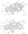
- Figure 1 shows a pallet 1 with an essentially rectangular basic structure 2 and four side surfaces enclosing the basic structure 2 3. Of the four side surfaces 3, two side surfaces 3 are arranged on opposite sides of the basic structure 2 and aligned parallel to one another. Apart from structural stiffening structures, the basic structure 2 has an essentially flat upper side 4 and an essentially flat lower side 5, the latter in the top view of FIG Figure 1 cannot be seen. In addition, the basic structure 2 is mirror-symmetrical to an imaginary center line 14 running in the longitudinal direction of the pallet 1, ie elements and sections of one side are mirror-symmetrical on the other side of the center line 14, even if they are not provided with reference numerals.
- funnel-shaped depressions 16 are provided, each forming a foot 6 for supporting the basic structure 2 from a floor surface.
- a central truncated pyramid 24 extends from the bottom of the depression 16 (see Figure 2 ) upwards, the surface of which is flush with the pallet top 4.
- Two of the four feet 6 have an elongated cross section, the longer axes of which are aligned parallel to the longitudinal axis of the pallet 1.
- one of the narrower walls is cut out, so that a passage 17 extending from the upper side 4 of the basic structure 2 to the lower side 5 of the basic structure 2 is formed.
- Each of the four side surfaces 3 has a centrally arranged recess 7 for receiving a display extension 8 (in Figure 1 not shown).
- a display extension 8 in Figure 1 not shown.
- vertically extending undercuts 9 are provided on the vertically extending boundaries of the recess 7, the undercuts 9 extending over the entire vertical extent of the recess 7.
- the horizontal cross-sectional area 10 of the recess 7 is rectangular and decreases from the bottom to the top 5, 4.
- the corners 12 of the pallet 1 are offset inwards and thus offer a further fastening possibility for projections arranged at the corners of the display, which can be put over the corners 12 of the pallet 1 offset inwards, for example.
- the receptacles 13 are rectangular slots which are arranged in the upper side 4 of the basic structure 2 and have four side walls which extend to the lower side 5. The height of these side walls corresponds to at least twice the minimum width of the slots.
- the basic structure of in Figure 1 also has two slot-shaped receptacles 13, arranged parallel to one another, for a fastening means along an imaginary line running parallel to one of the side surfaces 3.
- the basic structure 2 of the pallet 1 according to the invention has ten slot-shaped receptacles 13 on the upper side 4 - two receptacles 13 arranged on the center line and two receptacles 13 running parallel to the respective edges of the side surfaces 3 - which serve to hold fastening means.
- FIG 2 is a perspective view of the embodiment according to the Figure 1 shown.
- the basic structure 2 is alternately made up of ribs and depressions 18 which are stiffened by transverse struts, the basic structure 2 has an essentially flat top and bottom 4, 5. Both on the top 4 and on the bottom 5, fixing sections 19 are provided for fastening fixing bands.
- the fixing sections 19 are punched out of the respective top and bottom sides 4, 5. They have an elongated shape with rounded corners.
- the feet 6 are clearly recognizable on their outer side with a recess 15 for fastening packaging material and / or fastening means.
- the recesses 15 are triangular here and are arranged on the side surfaces of each foot 6, which run along the longitudinal direction of the pallet 1.
- the recesses 7 have vertically extending undercuts 9 at their vertically extending boundaries, the undercuts 9 extending over the entire vertical extent of the recess 7.
- the recesses 7 here in turn extend over the entire vertical extent of the respective side surface 3. In other words, each of the four side surfaces 3 is interrupted by one of the four recesses 7.
- the horizontal cross-sectional area 10 of the recess 7 is essentially rectangular, the horizontal cross-sectional area 10 decreasing from the underside 5 in the direction of the top 4. Due to the rectangular shape of the horizontal cross-sectional area 10 and its decrease in the direction of the top 4 of the basic structure, the recess 7 has a wedge-shaped profile tapering upwards in a section perpendicular to the side surface 3. A display extension 8 which is introduced into the recess 7 and has a corresponding wedge profile can, on the one hand, contact the rear boundary surface of the recess 7 and is supported thereby. On the other hand, folded-over wedge sections 22 engage behind the vertically extending webs 23, which form the undercuts 9, and thus prevent the display extension 8 from being able to be moved upward or laterally out of the recess 7.
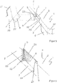
- FIG Figure 3 A perspective view of an embodiment according to the invention obliquely from below is shown in FIG Figure 3 shown.
- the top and bottom 4, 5 of the basic structure 2 are complementary to each other.
- Several pallets 1 can be stacked one above the other.
- FIG. 10 is a partially sectional perspective view of an embodiment according to FIG Figure 3 shown.
- the feet 6 are formed by a funnel-shaped depression 16 extending from the top 4, a central truncated pyramid 24 extending from the bottom of the depression 16 to the top 4.
- the end of the truncated pyramid 6 is flush with the top 4 of the basic structure 2.
- the basic structure has 2 depressions and ribs 18. These structures, alternately open at the top and bottom, are stiffened with cross struts and each define a level of the top and bottom 5, 4 of the pallet 1.
- Figure 5 shows a section of a pallet 1 according to the invention with recesses 7 for receiving a display extension 8.
- Two of the feet 6 supporting the basic structure 2 are shown, one foot 6 having an essentially elongated cross section compared to the other foot 6.
- a recess 15 is not provided in any of the side surfaces of the feet 6.
- a recess 7 for receiving a display extension 8 is provided on one side surface 3 shown. Recognizable, the recess 7 extends over the vertical extension of the side surface 3, so that the side surface 3 is interrupted by the recess 7.
- the recess 7 has vertically extending undercuts 9 at its vertically extending boundaries, which extend over the entire extend vertically of the recess 7 and are formed by webs 23 which extend flush with the side wall surface from the lateral boundaries of the recesses 7 and into the latter. Since the horizontal cross-sectional area 10 of the recess 7 (in Figure 5 indicated by a dashed line) decreases from the bottom 5 of the base structure 2 to the top 4 of the base structure, the side profile of the recess 7 and the undercuts 9 are wedge-shaped.
- a dovetail-shaped display extension 8 can be pressed into the recess 7 from the side, the lateral wedge sections 22 of the display extension 8 bending along a pre-folded line and partially bending open again after passing the webs 23 and engaging in the vertically extending undercuts 9.
- the fold edge lies against the rear wall boundary of the recess 7 and thus ensures that the wedge sections 22 are held in the undercuts 9 in a positive and non-positive manner.
- the wedge-like shape of the side undercut profile prevents the display extension 8 from being moved upwards out of the recess 7. Sliding down is prevented either by the display 20 resting on the top 4 of the pallet 1 or by engagement of projections in the recesses 11 of the webs 23.
- the display extension 8 is also supported on the rear wall boundary of the recess 7, which increases the stability. As shown here, the display 20 and the display extension 8 can have a corrugated cardboard structure 22.
- the basic structure 2 has inwardly offset corners 12.
- FIG. 6 A partial sectional view showing a perspective view of an embodiment according to Figure 5 with an engaged display extension 8 is in Figure 6 shown.
- the pallet 1 with an essentially rectangular basic structure 2 has four side surfaces 3 enclosing the basic structure 2 (only one of which is shown here).
- the side surface 3 has a recess 7, into which a display extension 8 is introduced.
- the display extension 8 has a corrugated cardboard structure 21 and two wedge sections 22 which can be bent along a pre-folded line.
- the bent wedge sections 22 engage in the vertically running undercuts 9 of the recess 7 and thus fix the display extension 8 in the recess 7. Because the horizontal cross-sectional area 10 of the recess 7 is rectangular and decreases from the underside 5 of the basic structure 2 in the direction of the top 4 , the side profile of the recess 7 is wedge-shaped.
- the wedge shape means that the wedge sections 22 of the display extension 8 cannot be moved out of the recess 7 in the direction of the upper side 4 of the basic structure 2.
- the display extension 8 can be supported on the rear wall recess 7 over a large area, so that the stability of the fastening is increased.
- Figure 7 is a perspective section according to Figure 6 shown on another embodiment of the present invention.
- the pallet 1 has all the features of the embodiment shown in the previous figures.
- the recess 7 extends over the vertical extent of the side surface 3 and has a horizontal cross section 10 which is rectangular and which decreases from the bottom to the top 5, 4.
- the recess 7 has undercuts 9 at its vertical boundaries which extend over the extent of the recess 7.
- the Undercuts 9 have a lateral wedge profile, into which, as shown here, a wedge section 22 of the display extension can engage.
- the webs 23 forming the undercuts 9 here have a horizontally running recess 11 into which a nose arranged on the wedge sections 22 can engage, whereby a vertical movement of the display extension 8 in the recess 7 can be prevented. Due to the slot-shaped recess 11, it is also possible to detach the wedge sections 22 from the undercut 9 if necessary. For this purpose, for example, a tool can be inserted into the slot-shaped recesses 11 with which the wedge sections 22 can be bent and pulled out of the undercuts 22. If the lugs introduced into the horizontally running recesses 11 protrude beyond the side surface 3, then no tools are required to bend the wedge sections 22 and to lead them out of the undercut 9.
Landscapes
- Engineering & Computer Science (AREA)
- Mechanical Engineering (AREA)
- Pallets (AREA)
Applications Claiming Priority (4)
| Application Number | Priority Date | Filing Date | Title |
|---|---|---|---|
| DE102011003999A DE102011003999A1 (de) | 2011-02-11 | 2011-02-11 | Palette |
| EP18183163.7A EP3403942B1 (de) | 2011-02-11 | 2012-02-08 | Palette |
| EP14004418.1A EP2878550A1 (de) | 2011-02-11 | 2012-02-08 | Palette |
| EP12154453.0A EP2487117B1 (de) | 2011-02-11 | 2012-02-08 | Palette |
Related Parent Applications (3)
| Application Number | Title | Priority Date | Filing Date |
|---|---|---|---|
| EP14004418.1A Division EP2878550A1 (de) | 2011-02-11 | 2012-02-08 | Palette |
| EP18183163.7A Division EP3403942B1 (de) | 2011-02-11 | 2012-02-08 | Palette |
| EP12154453.0A Division EP2487117B1 (de) | 2011-02-11 | 2012-02-08 | Palette |
Publications (1)
| Publication Number | Publication Date |
|---|---|
| EP3636558A1 true EP3636558A1 (de) | 2020-04-15 |
Family
ID=45566910
Family Applications (6)
| Application Number | Title | Priority Date | Filing Date |
|---|---|---|---|
| EP14004358.9A Active EP2878548B1 (de) | 2011-02-11 | 2012-02-08 | Palette |
| EP18183163.7A Active EP3403942B1 (de) | 2011-02-11 | 2012-02-08 | Palette |
| EP12154453.0A Active EP2487117B1 (de) | 2011-02-11 | 2012-02-08 | Palette |
| EP14004418.1A Ceased EP2878550A1 (de) | 2011-02-11 | 2012-02-08 | Palette |
| EP19213762.8A Pending EP3636558A1 (de) | 2011-02-11 | 2012-02-08 | Palette |
| EP14004359.7A Active EP2878549B1 (de) | 2011-02-11 | 2012-02-08 | Palette |
Family Applications Before (4)
| Application Number | Title | Priority Date | Filing Date |
|---|---|---|---|
| EP14004358.9A Active EP2878548B1 (de) | 2011-02-11 | 2012-02-08 | Palette |
| EP18183163.7A Active EP3403942B1 (de) | 2011-02-11 | 2012-02-08 | Palette |
| EP12154453.0A Active EP2487117B1 (de) | 2011-02-11 | 2012-02-08 | Palette |
| EP14004418.1A Ceased EP2878550A1 (de) | 2011-02-11 | 2012-02-08 | Palette |
Family Applications After (1)
| Application Number | Title | Priority Date | Filing Date |
|---|---|---|---|
| EP14004359.7A Active EP2878549B1 (de) | 2011-02-11 | 2012-02-08 | Palette |
Country Status (4)
| Country | Link |
|---|---|
| EP (6) | EP2878548B1 (pl) |
| DE (1) | DE102011003999A1 (pl) |
| ES (2) | ES2533183T3 (pl) |
| PL (2) | PL3403942T3 (pl) |
Families Citing this family (20)
| Publication number | Priority date | Publication date | Assignee | Title |
|---|---|---|---|---|
| DE202015104613U1 (de) * | 2015-08-31 | 2015-09-22 | Cabka Gmbh & Co. Kg | Display-Palette aus Kunststoff |
| ES2673431T3 (es) | 2015-08-31 | 2018-06-21 | Cabka Gmbh & Co. Kg | Palet de expositor de plástico |
| DE102015012066A1 (de) | 2015-09-22 | 2017-03-23 | Karimov GmbH | Transportpalette, Modul und Faltbogen dafür sowie Verfahren zum Herstellen einer Transportpalette |
| RU2731187C2 (ru) | 2016-01-28 | 2020-08-31 | Чеп Текнолоджи Пти Лимитед | Тележка |
| US11225356B2 (en) | 2017-08-16 | 2022-01-18 | Chep Technology Pty Limited | Stackable fractional plastic pallet |
| FI20175880A1 (fi) * | 2017-10-09 | 2019-04-10 | Wimao Oy | Rakenne-elementti, menetelmä sen valmistamiseksi ja käyttö |
| CA188144S (en) | 2018-12-20 | 2020-09-03 | Chep Technology Pty Ltd | Pallet attachment |
| US11174070B2 (en) * | 2019-08-07 | 2021-11-16 | Rehrig Pacific Company | Stackable pallet |
| DE202021103163U1 (de) | 2021-06-10 | 2022-09-20 | Ipp Gmbh | Ladungsträger |
| DE102021115056A1 (de) | 2021-06-10 | 2022-12-15 | Ipp Gmbh | Ladungsträger |
| DE102021115057A1 (de) | 2021-06-10 | 2022-12-15 | Ipp Gmbh | Ladungsträger |
| DE202021103161U1 (de) | 2021-06-10 | 2022-09-14 | Ipp Gmbh | Ladungsträger |
| DE202021103160U1 (de) | 2021-06-10 | 2022-09-15 | Ipp Gmbh | Ladungsträger |
| DE102021115058A1 (de) | 2021-06-10 | 2022-12-15 | Ipp Gmbh | Ladungsträger |
| DE202021106622U1 (de) | 2021-12-03 | 2023-03-27 | Ipp Gmbh | Ladungsträger |
| DE102021131955A1 (de) | 2021-12-03 | 2023-06-07 | Ipp Gmbh | Ladungsträger |
| DE102021131954A1 (de) | 2021-12-03 | 2023-06-07 | Ipp Gmbh | Ladungsträger |
| DE202021106621U1 (de) | 2021-12-03 | 2023-03-24 | Ipp Gmbh | Ladungsträger |
| DE102022107556A1 (de) | 2022-03-30 | 2023-10-05 | Schoeller Allibert Gmbh | System mit zumindest einer leichtbaupalette und zumindest einer behälterlage mit einem oder mehreren behältern |
| EP4311791A1 (en) * | 2022-07-29 | 2024-01-31 | Motherson Innovations Company Ltd. | Pallet |
Citations (8)
| Publication number | Priority date | Publication date | Assignee | Title |
|---|---|---|---|---|
| FR1397498A (fr) * | 1964-03-20 | 1965-04-30 | J A Benoit S A Soc | Dispositif de chargement sur palettes |
| FR2128054A1 (fr) * | 1971-03-02 | 1972-10-20 | Papeteries De Lumbres | Palette pour le classement et le transport d'objets ou de materiaux |
| DE3806069A1 (de) * | 1987-02-26 | 1988-09-15 | Schoeller & Co Ag A | Palette |
| DE9304350U1 (pl) * | 1993-03-23 | 1993-05-27 | Siemens Nixdorf Informationssysteme Ag, 4790 Paderborn, De | |
| EP1473247A2 (en) * | 2003-04-28 | 2004-11-03 | The Boeing Company | Enhanced aerial delivery system (eads) platform |
| DE202005004645U1 (de) * | 2005-03-16 | 2005-05-25 | Smurfit Europa Carton Gmbh | Verbundanordnung eines Transportbehälters mit einer Palette sowie Behälterzuschnitt und Palette für die Verbundanordnung |
| WO2010057586A1 (de) | 2008-11-19 | 2010-05-27 | Aks Kunststoff Systeme Gmbh & Co. Kg | Kunststoffpalette |
| GB2486661A (en) * | 2010-12-21 | 2012-06-27 | Smurfit Kappa Corrugated Uk Ltd | Container locking mechanism |
Family Cites Families (6)
| Publication number | Priority date | Publication date | Assignee | Title |
|---|---|---|---|---|
| DE59200995D1 (de) * | 1991-07-23 | 1995-01-26 | Siemens Nixdorf Inf Syst | Mehrwegcontainer zur verpackung von gütern aller art. |
| US20050145144A1 (en) * | 2004-01-05 | 2005-07-07 | Gab Christopher N. | Pallet |
| EP1705130A1 (en) * | 2005-03-21 | 2006-09-27 | AVK Plastics B.V. | Pallet and method of securing goods onto a pallet |
| DE202009018185U1 (de) * | 2009-10-22 | 2011-05-12 | Lidl Stiftung & Co. Kg | Kunststoffpalette für den Transport von Gütern |
| AU2010269108B2 (en) * | 2010-04-19 | 2011-07-07 | Vinex Singapore Pte Ltd | Pallets made of plastics or paper |
| DE202010016859U1 (de) * | 2010-12-22 | 2011-03-24 | Arpack Gmbh | Palette zur Aufnahme von Warenträgern |
-
2011
- 2011-02-11 DE DE102011003999A patent/DE102011003999A1/de active Pending
-
2012
- 2012-02-08 ES ES12154453.0T patent/ES2533183T3/es active Active
- 2012-02-08 PL PL18183163T patent/PL3403942T3/pl unknown
- 2012-02-08 EP EP14004358.9A patent/EP2878548B1/de active Active
- 2012-02-08 EP EP18183163.7A patent/EP3403942B1/de active Active
- 2012-02-08 ES ES18183163T patent/ES2773716T3/es active Active
- 2012-02-08 EP EP12154453.0A patent/EP2487117B1/de active Active
- 2012-02-08 PL PL12154453T patent/PL2487117T3/pl unknown
- 2012-02-08 EP EP14004418.1A patent/EP2878550A1/de not_active Ceased
- 2012-02-08 EP EP19213762.8A patent/EP3636558A1/de active Pending
- 2012-02-08 EP EP14004359.7A patent/EP2878549B1/de active Active
Patent Citations (8)
| Publication number | Priority date | Publication date | Assignee | Title |
|---|---|---|---|---|
| FR1397498A (fr) * | 1964-03-20 | 1965-04-30 | J A Benoit S A Soc | Dispositif de chargement sur palettes |
| FR2128054A1 (fr) * | 1971-03-02 | 1972-10-20 | Papeteries De Lumbres | Palette pour le classement et le transport d'objets ou de materiaux |
| DE3806069A1 (de) * | 1987-02-26 | 1988-09-15 | Schoeller & Co Ag A | Palette |
| DE9304350U1 (pl) * | 1993-03-23 | 1993-05-27 | Siemens Nixdorf Informationssysteme Ag, 4790 Paderborn, De | |
| EP1473247A2 (en) * | 2003-04-28 | 2004-11-03 | The Boeing Company | Enhanced aerial delivery system (eads) platform |
| DE202005004645U1 (de) * | 2005-03-16 | 2005-05-25 | Smurfit Europa Carton Gmbh | Verbundanordnung eines Transportbehälters mit einer Palette sowie Behälterzuschnitt und Palette für die Verbundanordnung |
| WO2010057586A1 (de) | 2008-11-19 | 2010-05-27 | Aks Kunststoff Systeme Gmbh & Co. Kg | Kunststoffpalette |
| GB2486661A (en) * | 2010-12-21 | 2012-06-27 | Smurfit Kappa Corrugated Uk Ltd | Container locking mechanism |
Also Published As
| Publication number | Publication date |
|---|---|
| EP2487117A1 (de) | 2012-08-15 |
| EP2878550A1 (de) | 2015-06-03 |
| EP2487117B1 (de) | 2014-12-31 |
| EP2878548B1 (de) | 2016-09-14 |
| EP2878549A1 (de) | 2015-06-03 |
| ES2533183T3 (es) | 2015-04-08 |
| EP3403942B1 (de) | 2019-12-11 |
| ES2773716T3 (es) | 2020-07-14 |
| DE102011003999A1 (de) | 2012-08-16 |
| EP2878548A1 (de) | 2015-06-03 |
| EP3403942A1 (de) | 2018-11-21 |
| PL2487117T3 (pl) | 2015-05-29 |
| EP2878549B1 (de) | 2016-07-20 |
| PL3403942T3 (pl) | 2020-08-24 |
Similar Documents
| Publication | Publication Date | Title |
|---|---|---|
| EP2487117B1 (de) | Palette | |
| EP3124391B1 (de) | Trägeranordnung | |
| EP3094568B1 (de) | Behälter für den transport von waren und vorrichtung zur unterteilung eines solchen behälters | |
| EP1754897B1 (de) | Lagerungsvorrichtung | |
| EP3569110B1 (de) | Blumenkasten | |
| DE602005000018T2 (de) | Lagersystem und Komponenten dafür | |
| EP3303731B1 (de) | Gerüstbodenelement, insbesondere für ein baugerüst | |
| DE2255086C2 (de) | Abstandhaltendes Verbindungsglied zur Herstellung einer mehrschaligen Wand | |
| DE4101486C2 (de) | Vorrichtung zum lösbaren Verbinden vorzugsweise flächiger Teile | |
| EP2324732B1 (de) | Lagerregal, insbesondere automatisches Kleinteilelager | |
| WO2011023188A2 (de) | Verlorene schalung und schalungssystem | |
| EP3753857B1 (de) | Wandelement eines paletten-aufsatzrahmens und paletten-aufsatzrahmen | |
| DE102012000242B4 (de) | Stapelbare Warenpalette | |
| EP2767483B1 (de) | Stapelbarer Transportbehälter | |
| EP1279356B1 (de) | Fachboden für ein Regal sowie Regal | |
| DE212020000379U1 (de) | Palette | |
| DE202014102178U1 (de) | Regal-Traverse | |
| EP2927157B1 (de) | Transportsicherung für Wickelrollen | |
| EP3659479B1 (de) | Wannenträger aus einem hartschaumstoff sowie zur versandanordnung gestapelte teile eines wannenträgers | |
| EP2526838B1 (de) | Regal aus einem knickbaren flächigen Material | |
| EP2227610B1 (de) | Tragstruktur | |
| EP3974347A1 (de) | Regalpaneel mit verformung | |
| WO2004113741A1 (de) | Möbelverbindung | |
| EP1066774B1 (de) | Lagerregal | |
| DE102017008168A1 (de) | Displayelement für warentragende Displays und Verfahren zur Herstellung eines warentragenden Displays |
Legal Events
| Date | Code | Title | Description |
|---|---|---|---|
| PUAI | Public reference made under article 153(3) epc to a published international application that has entered the european phase |
Free format text: ORIGINAL CODE: 0009012 |
|
| STAA | Information on the status of an ep patent application or granted ep patent |
Free format text: STATUS: THE APPLICATION HAS BEEN PUBLISHED |
|
| AC | Divisional application: reference to earlier application |
Ref document number: 3403942 Country of ref document: EP Kind code of ref document: P Ref document number: 2487117 Country of ref document: EP Kind code of ref document: P Ref document number: 2878550 Country of ref document: EP Kind code of ref document: P |
|
| AK | Designated contracting states |
Kind code of ref document: A1 Designated state(s): AL AT BE BG CH CY CZ DE DK EE ES FI FR GB GR HR HU IE IS IT LI LT LU LV MC MK MT NL NO PL PT RO RS SE SI SK SM TR |
|
| STAA | Information on the status of an ep patent application or granted ep patent |
Free format text: STATUS: REQUEST FOR EXAMINATION WAS MADE |
|
| 17P | Request for examination filed |
Effective date: 20200924 |
|
| RBV | Designated contracting states (corrected) |
Designated state(s): AL AT BE BG CH CY CZ DE DK EE ES FI FR GB GR HR HU IE IS IT LI LT LU LV MC MK MT NL NO PL PT RO RS SE SI SK SM TR |
|
| STAA | Information on the status of an ep patent application or granted ep patent |
Free format text: STATUS: EXAMINATION IS IN PROGRESS |
|
| 17Q | First examination report despatched |
Effective date: 20220707 |