EP2927157B1 - Transportsicherung für Wickelrollen - Google Patents
Transportsicherung für Wickelrollen Download PDFInfo
- Publication number
- EP2927157B1 EP2927157B1 EP14162558.2A EP14162558A EP2927157B1 EP 2927157 B1 EP2927157 B1 EP 2927157B1 EP 14162558 A EP14162558 A EP 14162558A EP 2927157 B1 EP2927157 B1 EP 2927157B1
- Authority
- EP
- European Patent Office
- Prior art keywords
- pallet
- holding
- end walls
- groove
- security device
- Prior art date
- Legal status (The legal status is an assumption and is not a legal conclusion. Google has not performed a legal analysis and makes no representation as to the accuracy of the status listed.)
- Not-in-force
Links
Images


Classifications
-
- B—PERFORMING OPERATIONS; TRANSPORTING
- B65—CONVEYING; PACKING; STORING; HANDLING THIN OR FILAMENTARY MATERIAL
- B65D—CONTAINERS FOR STORAGE OR TRANSPORT OF ARTICLES OR MATERIALS, e.g. BAGS, BARRELS, BOTTLES, BOXES, CANS, CARTONS, CRATES, DRUMS, JARS, TANKS, HOPPERS, FORWARDING CONTAINERS; ACCESSORIES, CLOSURES, OR FITTINGS THEREFOR; PACKAGING ELEMENTS; PACKAGES
- B65D85/00—Containers, packaging elements or packages, specially adapted for particular articles or materials
- B65D85/66—Containers, packaging elements or packages, specially adapted for particular articles or materials for jumbo rolls; for rolls of floor covering
-
- B—PERFORMING OPERATIONS; TRANSPORTING
- B65—CONVEYING; PACKING; STORING; HANDLING THIN OR FILAMENTARY MATERIAL
- B65D—CONTAINERS FOR STORAGE OR TRANSPORT OF ARTICLES OR MATERIALS, e.g. BAGS, BARRELS, BOTTLES, BOXES, CANS, CARTONS, CRATES, DRUMS, JARS, TANKS, HOPPERS, FORWARDING CONTAINERS; ACCESSORIES, CLOSURES, OR FITTINGS THEREFOR; PACKAGING ELEMENTS; PACKAGES
- B65D19/00—Pallets or like platforms, with or without side walls, for supporting loads to be lifted or lowered
- B65D19/38—Details or accessories
- B65D19/44—Elements or devices for locating articles on platforms
-
- B—PERFORMING OPERATIONS; TRANSPORTING
- B65—CONVEYING; PACKING; STORING; HANDLING THIN OR FILAMENTARY MATERIAL
- B65D—CONTAINERS FOR STORAGE OR TRANSPORT OF ARTICLES OR MATERIALS, e.g. BAGS, BARRELS, BOTTLES, BOXES, CANS, CARTONS, CRATES, DRUMS, JARS, TANKS, HOPPERS, FORWARDING CONTAINERS; ACCESSORIES, CLOSURES, OR FITTINGS THEREFOR; PACKAGING ELEMENTS; PACKAGES
- B65D2519/00—Pallets or like platforms, with or without side walls, for supporting loads to be lifted or lowered
- B65D2519/00004—Details relating to pallets
- B65D2519/00009—Materials
- B65D2519/00014—Materials for the load supporting surface
- B65D2519/00034—Plastic
-
- B—PERFORMING OPERATIONS; TRANSPORTING
- B65—CONVEYING; PACKING; STORING; HANDLING THIN OR FILAMENTARY MATERIAL
- B65D—CONTAINERS FOR STORAGE OR TRANSPORT OF ARTICLES OR MATERIALS, e.g. BAGS, BARRELS, BOTTLES, BOXES, CANS, CARTONS, CRATES, DRUMS, JARS, TANKS, HOPPERS, FORWARDING CONTAINERS; ACCESSORIES, CLOSURES, OR FITTINGS THEREFOR; PACKAGING ELEMENTS; PACKAGES
- B65D2519/00—Pallets or like platforms, with or without side walls, for supporting loads to be lifted or lowered
- B65D2519/00004—Details relating to pallets
- B65D2519/00009—Materials
- B65D2519/00049—Materials for the base surface
- B65D2519/00069—Plastic
-
- B—PERFORMING OPERATIONS; TRANSPORTING
- B65—CONVEYING; PACKING; STORING; HANDLING THIN OR FILAMENTARY MATERIAL
- B65D—CONTAINERS FOR STORAGE OR TRANSPORT OF ARTICLES OR MATERIALS, e.g. BAGS, BARRELS, BOTTLES, BOXES, CANS, CARTONS, CRATES, DRUMS, JARS, TANKS, HOPPERS, FORWARDING CONTAINERS; ACCESSORIES, CLOSURES, OR FITTINGS THEREFOR; PACKAGING ELEMENTS; PACKAGES
- B65D2519/00—Pallets or like platforms, with or without side walls, for supporting loads to be lifted or lowered
- B65D2519/00004—Details relating to pallets
- B65D2519/00009—Materials
- B65D2519/00154—Materials for the side walls
- B65D2519/00174—Plastic
-
- B—PERFORMING OPERATIONS; TRANSPORTING
- B65—CONVEYING; PACKING; STORING; HANDLING THIN OR FILAMENTARY MATERIAL
- B65D—CONTAINERS FOR STORAGE OR TRANSPORT OF ARTICLES OR MATERIALS, e.g. BAGS, BARRELS, BOTTLES, BOXES, CANS, CARTONS, CRATES, DRUMS, JARS, TANKS, HOPPERS, FORWARDING CONTAINERS; ACCESSORIES, CLOSURES, OR FITTINGS THEREFOR; PACKAGING ELEMENTS; PACKAGES
- B65D2519/00—Pallets or like platforms, with or without side walls, for supporting loads to be lifted or lowered
- B65D2519/00004—Details relating to pallets
- B65D2519/00258—Overall construction
- B65D2519/00263—Overall construction of the pallet
- B65D2519/00268—Overall construction of the pallet made of one piece
-
- B—PERFORMING OPERATIONS; TRANSPORTING
- B65—CONVEYING; PACKING; STORING; HANDLING THIN OR FILAMENTARY MATERIAL
- B65D—CONTAINERS FOR STORAGE OR TRANSPORT OF ARTICLES OR MATERIALS, e.g. BAGS, BARRELS, BOTTLES, BOXES, CANS, CARTONS, CRATES, DRUMS, JARS, TANKS, HOPPERS, FORWARDING CONTAINERS; ACCESSORIES, CLOSURES, OR FITTINGS THEREFOR; PACKAGING ELEMENTS; PACKAGES
- B65D2519/00—Pallets or like platforms, with or without side walls, for supporting loads to be lifted or lowered
- B65D2519/00004—Details relating to pallets
- B65D2519/00258—Overall construction
- B65D2519/00283—Overall construction of the load supporting surface
- B65D2519/00288—Overall construction of the load supporting surface made of one piece
-
- B—PERFORMING OPERATIONS; TRANSPORTING
- B65—CONVEYING; PACKING; STORING; HANDLING THIN OR FILAMENTARY MATERIAL
- B65D—CONTAINERS FOR STORAGE OR TRANSPORT OF ARTICLES OR MATERIALS, e.g. BAGS, BARRELS, BOTTLES, BOXES, CANS, CARTONS, CRATES, DRUMS, JARS, TANKS, HOPPERS, FORWARDING CONTAINERS; ACCESSORIES, CLOSURES, OR FITTINGS THEREFOR; PACKAGING ELEMENTS; PACKAGES
- B65D2519/00—Pallets or like platforms, with or without side walls, for supporting loads to be lifted or lowered
- B65D2519/00004—Details relating to pallets
- B65D2519/00258—Overall construction
- B65D2519/00313—Overall construction of the base surface
- B65D2519/00318—Overall construction of the base surface made of one piece
-
- B—PERFORMING OPERATIONS; TRANSPORTING
- B65—CONVEYING; PACKING; STORING; HANDLING THIN OR FILAMENTARY MATERIAL
- B65D—CONTAINERS FOR STORAGE OR TRANSPORT OF ARTICLES OR MATERIALS, e.g. BAGS, BARRELS, BOTTLES, BOXES, CANS, CARTONS, CRATES, DRUMS, JARS, TANKS, HOPPERS, FORWARDING CONTAINERS; ACCESSORIES, CLOSURES, OR FITTINGS THEREFOR; PACKAGING ELEMENTS; PACKAGES
- B65D2519/00—Pallets or like platforms, with or without side walls, for supporting loads to be lifted or lowered
- B65D2519/00004—Details relating to pallets
- B65D2519/00258—Overall construction
- B65D2519/00313—Overall construction of the base surface
- B65D2519/00328—Overall construction of the base surface shape of the contact surface of the base
- B65D2519/00338—Overall construction of the base surface shape of the contact surface of the base contact surface having a discrete foot-like shape
-
- B—PERFORMING OPERATIONS; TRANSPORTING
- B65—CONVEYING; PACKING; STORING; HANDLING THIN OR FILAMENTARY MATERIAL
- B65D—CONTAINERS FOR STORAGE OR TRANSPORT OF ARTICLES OR MATERIALS, e.g. BAGS, BARRELS, BOTTLES, BOXES, CANS, CARTONS, CRATES, DRUMS, JARS, TANKS, HOPPERS, FORWARDING CONTAINERS; ACCESSORIES, CLOSURES, OR FITTINGS THEREFOR; PACKAGING ELEMENTS; PACKAGES
- B65D2519/00—Pallets or like platforms, with or without side walls, for supporting loads to be lifted or lowered
- B65D2519/00004—Details relating to pallets
- B65D2519/00258—Overall construction
- B65D2519/00398—Overall construction reinforcements
- B65D2519/00402—Integral, e.g. ribs
- B65D2519/00422—Integral, e.g. ribs on the walls
-
- B—PERFORMING OPERATIONS; TRANSPORTING
- B65—CONVEYING; PACKING; STORING; HANDLING THIN OR FILAMENTARY MATERIAL
- B65D—CONTAINERS FOR STORAGE OR TRANSPORT OF ARTICLES OR MATERIALS, e.g. BAGS, BARRELS, BOTTLES, BOXES, CANS, CARTONS, CRATES, DRUMS, JARS, TANKS, HOPPERS, FORWARDING CONTAINERS; ACCESSORIES, CLOSURES, OR FITTINGS THEREFOR; PACKAGING ELEMENTS; PACKAGES
- B65D2519/00—Pallets or like platforms, with or without side walls, for supporting loads to be lifted or lowered
- B65D2519/00004—Details relating to pallets
- B65D2519/00258—Overall construction
- B65D2519/00492—Overall construction of the side walls
- B65D2519/00497—Overall construction of the side walls whereby at least one side wall is made of one piece
-
- B—PERFORMING OPERATIONS; TRANSPORTING
- B65—CONVEYING; PACKING; STORING; HANDLING THIN OR FILAMENTARY MATERIAL
- B65D—CONTAINERS FOR STORAGE OR TRANSPORT OF ARTICLES OR MATERIALS, e.g. BAGS, BARRELS, BOTTLES, BOXES, CANS, CARTONS, CRATES, DRUMS, JARS, TANKS, HOPPERS, FORWARDING CONTAINERS; ACCESSORIES, CLOSURES, OR FITTINGS THEREFOR; PACKAGING ELEMENTS; PACKAGES
- B65D2519/00—Pallets or like platforms, with or without side walls, for supporting loads to be lifted or lowered
- B65D2519/00004—Details relating to pallets
- B65D2519/00547—Connections
- B65D2519/00577—Connections structures connecting side walls, including corner posts, to each other
- B65D2519/00631—Connections structures connecting side walls, including corner posts, to each other sidewalls not connected to each other, e.g. spaced apart frames
-
- B—PERFORMING OPERATIONS; TRANSPORTING
- B65—CONVEYING; PACKING; STORING; HANDLING THIN OR FILAMENTARY MATERIAL
- B65D—CONTAINERS FOR STORAGE OR TRANSPORT OF ARTICLES OR MATERIALS, e.g. BAGS, BARRELS, BOTTLES, BOXES, CANS, CARTONS, CRATES, DRUMS, JARS, TANKS, HOPPERS, FORWARDING CONTAINERS; ACCESSORIES, CLOSURES, OR FITTINGS THEREFOR; PACKAGING ELEMENTS; PACKAGES
- B65D2519/00—Pallets or like platforms, with or without side walls, for supporting loads to be lifted or lowered
- B65D2519/00004—Details relating to pallets
- B65D2519/00547—Connections
- B65D2519/00636—Connections structures connecting side walls to the pallet
- B65D2519/00641—Structures intended to be disassembled
- B65D2519/00661—Structures intended to be disassembled side walls maintained connected to pallet by means of auxiliary locking elements, e.g. spring loaded locking pins
-
- B—PERFORMING OPERATIONS; TRANSPORTING
- B65—CONVEYING; PACKING; STORING; HANDLING THIN OR FILAMENTARY MATERIAL
- B65D—CONTAINERS FOR STORAGE OR TRANSPORT OF ARTICLES OR MATERIALS, e.g. BAGS, BARRELS, BOTTLES, BOXES, CANS, CARTONS, CRATES, DRUMS, JARS, TANKS, HOPPERS, FORWARDING CONTAINERS; ACCESSORIES, CLOSURES, OR FITTINGS THEREFOR; PACKAGING ELEMENTS; PACKAGES
- B65D2519/00—Pallets or like platforms, with or without side walls, for supporting loads to be lifted or lowered
- B65D2519/00004—Details relating to pallets
- B65D2519/00736—Details
- B65D2519/0081—Elements or devices for locating articles
-
- B—PERFORMING OPERATIONS; TRANSPORTING
- B65—CONVEYING; PACKING; STORING; HANDLING THIN OR FILAMENTARY MATERIAL
- B65D—CONTAINERS FOR STORAGE OR TRANSPORT OF ARTICLES OR MATERIALS, e.g. BAGS, BARRELS, BOTTLES, BOXES, CANS, CARTONS, CRATES, DRUMS, JARS, TANKS, HOPPERS, FORWARDING CONTAINERS; ACCESSORIES, CLOSURES, OR FITTINGS THEREFOR; PACKAGING ELEMENTS; PACKAGES
- B65D2519/00—Pallets or like platforms, with or without side walls, for supporting loads to be lifted or lowered
- B65D2519/00004—Details relating to pallets
- B65D2519/00736—Details
- B65D2519/00935—Details with special means for nesting or stacking
- B65D2519/00955—Details with special means for nesting or stacking stackable
- B65D2519/00965—Details with special means for nesting or stacking stackable when loaded
- B65D2519/00975—Details with special means for nesting or stacking stackable when loaded through the side walls
Definitions
- sheet material in particular plastic film
- a winding core the combination of the winding core with the web-like material located thereon is referred to as a winding roll.
- the winding core typically consists of a sleeve made of plastic or a rigid cardboard.
- the winding core is supported on its end faces by means of so-called end walls, which cause the underside of the wound web-shaped material is arranged at a distance above the ground.
- the end walls either in the winding core axially projecting bearing journal or bearing bores, are inserted into the bearing bushes, which in turn enter the winding core.
- the two end walls form with the winding core or the winding roll a bearing assembly which is arranged on a pallet.
- Such end walls are used for example in the EP 0 753 469 B1 described, these end walls each consist of a rectangular plate. On one of the winding roll facing the front of this plate are a ring attachment and a central Inserted arranged. At the two opposite edges of this plate are perpendicular to the plate arranged side surfaces, wherein two of the opposite side surfaces have a smooth surface and the other two opposite side surfaces are structured differently. The four side surfaces are connected by rounded corners.
- the first of the structured side surfaces has corrugations, which are designed such that slip resistance is imparted when the end wall is placed on a wooden pallet.
- the second of the structured side surfaces also also has troughs which correspond to another side wall of the storage composite so that two bearing assemblies can be stacked on top of each other.
- the end walls are fastened with the bearing assembly arranged therebetween with transport or tension bands on the pallet.
- the end walls by means of plastic or wooden strips, which are bolted to the pallet, against lateral slipping, ie in the direction of the longitudinal axis of the winding core are secured. This requires individual, manual work and is therefore complicated and expensive.
- the pallet on which the bearing assembly is to be mounted is divided into two parts, so that a distance between the two pallet halves can be adapted to the distance between the two end walls or to the length of the winding roll.
- the two halves of the pallets are connected to each other via bars, whereby the bars protrude more or less into openings of the pallet halves, depending on the distance. If the pallet halves are in the correct position, the beams are attached to the respective pallet half so that the pallet halves can not slip further apart. In addition, a sliding apart of the end walls during the transport of the winding core is prevented by being held together with metal or plastic belt.
- This transport system can not be combined with common transport systems, whereby always an entire new transport system must be purchased, which is associated with high acquisition costs.
- Another disadvantage is that the transport of the composite bearing on the two pallet halves, when the two pallet halves are pushed apart, is difficult because the opening for the introduction, for example, forks of a forklift are very far apart.
- the beams are not suitable as a storage area for the forks of a forklift, since the beams do not have sufficient strength.
- the present invention is based on the object to provide a reliable, cost-effective and easy transport protection of the bearing assembly of winding roll and end walls on a pallet available, with a stable securing different lengths bobbins to be made possible by a precise adjustability of the distance between the two end walls.
- the underlying object is achieved in that between holding means and end wall, a holding element is arranged, and that the end wall and the holding means are each releasably positively connected to the holding element, wherein the end wall by means of the holding element in the Holding means is attached.
- the retaining means can be dispensed with the attachment of the end walls on the pallet by means of complex to be mounted connection and auxiliary means such as bolted plastic or wooden strips.
- auxiliary means such as bolted plastic or wooden strips.
- the attachment of the end walls is considerably simplified and also accelerated.
- the holding means according to the invention are made of plastic, so that the hygienic circumstances can be improved.
- the holding means are first inserted or inserted on the pallet, so that in relation to a displacement parallel to the surface of the pallet, a positive connection is formed. Subsequently, the end walls are mounted with the winding roll arranged therebetween perpendicular to the holding elements and holding means, wherein a Longitudinal axis of the winding roll is arranged perpendicular to the end wall and parallel to the pallet. Again, there is a positive connection in relation to a displacement of the end wall relative to the respective holding means.
- the end walls are typically removed from the holding means or the pallet. Subsequently, the holding means can be released again from the pallet, wherein the holding means can preferably be used several times.
- the storage of the holding means and the pallets takes up less space by removing the holding means.
- the holding means can not only be arranged several times on different pallets, but it is preferably provided that the holding means can be attached to common pallets, so that can be dispensed with the purchase of special pallets and thus costs can be saved.
- the holding means is connected via a tongue and groove connection and / or a pin-recess connection with the pallet.
- the pallet groove or exception is preferably located in the pallet and the spring or the pin on one side of the holding means facing the pallet. Nevertheless, by means of these types of connection sufficient force transmission can take place, so that the winding roll is sufficiently secured with the web-shaped material during transport and is not damaged, that is, rocking of the end walls in the direction of the longitudinal axis of the winding roll and thus damaging the film cut edges is avoided.
- the tongue and groove connection can also be a combination of two tooth geometries.
- the pallet grooves are preferably arranged at regular intervals from each other.
- the arrangement of several pallet grooves in the pallet allows a transport of different lengths winding rollers with the same range, since the holding means can be solved after each transport of the pallet and used again in a different position.
- a position of the holding means on the pallet can thus be adapted to the distance between the two end walls accordingly. Consequently, only one standard size of the pallet is needed be kept ready.
- the transport of the pallet can be standardized because the distance, for example, two forks of a forklift can always remain the same orientation and does not need to be changed constantly.
- the holding means has at least one holding means groove on a surface facing away from the pallet, wherein the holding means groove is arranged at a first angle to the longitudinal axis of the winding roll, wherein the angle is preferably 45 degrees.
- the retaining element is in particular mounted in the retaining mean groove, wherein the retaining element preferably has adjacent to a groove bottom two mutually opposite groove cheeks. The groove bottom is arranged at an equal angle to the longitudinal axis of the winding roll as the holding agent groove in the holding means.
- the two groove cheeks of the holding element are preferably fastened to the groove bottom such that they are arranged with their respective horizontal longitudinal axis parallel to the end wall and perpendicular to the longitudinal axis of the winding roll. Consequently, the groove bottom is configured parallelogram-shaped.
- This arrangement of the retaining agent groove and thus of the retaining element has the advantage that, with a large displacement of the retaining element in the retaining center groove, a smaller displacement of the groove cheeks of the retaining element occurs in a direction perpendicular to the end wall and parallel to the pallet. Consequently, the holding means can be adjusted so that even very small differences in the length of the winding rolls can be compensated, that is, it is a very finely divided adjustment possible. Accordingly, standard dimensions can be dispensed with in the winding rolls.
- the retaining element has a fastening tongue which, on its side facing the retaining means, has a row of teeth which preferably corresponds to a further row of teeth arranged perpendicularly to the retaining means grooves in the retaining means groove and the two rows of teeth form a toothing, the end walls preferably in the installed state with your weight force the two rows of teeth in contact.
- the holding element can no longer be displaced in a direction perpendicular to the longitudinal axis of the holding means groove.
- the holding element is preferably introduced into the holding means groove such that an upper side of the holding means, ie a side facing the end wall, is level with the top of the groove bottom of the holding element, whereby a displacement of the holding element in a direction perpendicular to the first angle through the Grooved walls of the retaining agent groove is prevented.
- the holding element on its side facing away from the holding means has a Halteelementnut, which is shaped so that the end walls with their depth in the width the Halteelementnut fit.
- the Halteelementnut has the two groove cheeks and the floor.
- the end walls have on their side surfaces at least one groove for receiving a conveyor belt.
- the at least one conveyor belt is passed from the one end wall under the pallet to the next end wall and then again to the first end wall on a side remote from the pallet side of the end wall.
- support struts are arranged between the opposite end walls on a corner of the respective end wall facing away from the pallet.
- the struts prevent the sidewalls from tilting in the direction of the winding roll or away from it. That is, by means of the support struts, the side walls are better supported and thus a sufficient support of the winding roll can be ensured.
- the holding means and / or holding elements be adapted to the length of the winding roll, but it is inventively provided that the support struts are adjustable in their length.
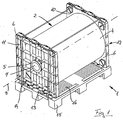
- FIG. 1 an inventive transport lock 1 for bobbins 2 is shown, wherein the winding rollers 2 a winding core 3 according to FIG. 3 having a tubular average and web-shaped Good 4 have.
- the winding roll 2 is fastened by means of bearing bushes 5 on two end walls 6 . Both end walls 6 have an opening 7 in the form of a center hole, through which the bearing bushes 5 in an inside 8 according to FIG. 3 the winding core 3 are guided.
- a longitudinal axis 9 of the winding roll 2 is arranged horizontally and corresponds to a longitudinal axis of the opening 7.
- the end walls 6 each have a front side 10 aligned with one another and a rear side 11 facing away from the winding roller 2 .
- the winding roller 2 with the two end walls 6 forms a bearing assembly 12 of the four holding means 13 with four associated holding elements 14 according to FIG. 7 is mounted on a pallet 15.
- the pallet 15 is arranged horizontally and has a plurality of pallet grooves 16.
- conveyor belts 17 By means of conveyor belts 17, the end walls 6 are additionally stabilized.
- the conveyor belts 17 pass under the pallet 15 along the two end walls 6 along the winding roll 2, wherein the conveyor belts 17 do not touch the winding roll 2.
- each support strut 46 is formed by two outer elements 47, 48 and a central element 49, wherein the two outer elements 47, 48 arranged in the central element 49 and by means of a tongue and groove connection 50 are connected.
- a length of the support struts 46 can be adjusted to a distance between the two opposite end faces 6.
- FIG. 2a represents an enlargement of the connection between the central member 49 and the outer member 47.
- the tongue and groove connection 50 is located on a side facing away from the pallet 15 side of the support struts 46.
- a tongue and groove connection 51 according to FIG. 2b also be arranged on two opposite vertical sides 52, 53 of the support struts 46.
- the FIG. 3 shows a vertical section along the longitudinal axis 9 of the winding roll 2.
- the winding core 3 with the web-shaped Good 4 thereon, is fixed by means of the bearing bushes 5 on the end walls 6, so that between the pallet 15 and the web-shaped Good 4 there is a distance A.
- the longitudinal axis 9 of the winding core 3 or the winding roller 2 is horizontal and is identical to a longitudinal axis of the bearing bushes 5. Furthermore, it is visible that the two end walls 6 are mounted on two opposite sides of the winding roll 2 perpendicular to the pallet 15.
- FIG. 4 the winding roll facing front side 10 of one of the two end walls 6 is shown.
- the opening 7 through which normally the bearing bush is guided.
- the end wall 6 has four side surfaces, which are arranged perpendicular to the end wall 6.
- elevations 19 and troughs 20 In the upper side surface 18 are elevations 19 and troughs 20, a so-called Stapelarret réelle, which corresponds to a further Stapelarret réelle, ie with elevations and troughs, an end wall, not shown, so that the end wall, not shown here, are arranged on the end wall 6 shown here could.
- a Rifflung 22 in the form of an anti-slip Rifflung, which prevents the end walls 6 can be moved in a direction perpendicular to the longitudinal axis 9 of the winding roll 2.
- the end wall 6 is mounted by means of the holding element 14 in the holding means 13, wherein both the holding element 14 and the holding means 13 are normally already arranged on the pallet.
- FIG. 5 shows the back 11 of the end wall 6 according to FIG. 4 and the retaining means 13 and the retaining element 14.
- the back 11 has horizontal ribs 23 and vertical ribs 24, so that the end wall 6, despite its light weight, has sufficient stability.
- FIG. 6 shows a side view of the end wall 6, the holding means 13 and the holding member 14 according to FIG. 4 , wherein the end wall 6 has a depth T.
- FIG. 7 the holding means 13 according to the invention is shown with the installed holding element 14 according to the invention.
- the holding means 13 has on its side facing away from the range not shown top 26 two crossed Garffennuten 27, 28, which are formed by groove walls 29 and a groove bottom 30.
- An angle not shown here between a first holding means groove 31 or a second holding means groove 32 and the longitudinal axis of the winding roll, not shown here, is 45 degrees or 135 degrees. Consequently, an angle ⁇ between the first holding agent groove 31 and the second holding agent groove 32 is 90 degrees.
- the holding element 14 can be arranged either in the first holding means groove 27 or in the second holding means groove 28, the holding element 14 having a holding element groove 33 with a groove bottom 34 and two groove cheeks 35.
- a longitudinal axis 36 of the groove cheeks 35 is arranged perpendicular to the longitudinal axis of the winding roll, not shown here, so that the end walls, not shown here, can be arranged perpendicular to the longitudinal axis of the winding roll in the holding element 14.
- a top surface 37 of the groove bottom 34 is parallelogram-shaped.
- a width B between the groove cheeks 35 corresponds to the depth T of the end wall 6 according to FIG. 6 ,
- the holding means 13 facing away from the top 37 of the groove bottom 34 and the groove walls 29 of the holding means 13 have a same height H.
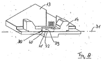
- a fixing tongue 39 which protrudes in the uninstalled state in the Garelementnut 33 and at its the retaining means 13 facing side 40 according to FIG. 8 a row of teeth 41 having with another row of teeth 42 in the holding means 13 correspond.
- the row of teeth 42 is arranged perpendicular to the two GarstoffverInstitutn 31, 32 .
- the row of teeth 41 of the holding element 14 forms a toothing 38 with the row of teeth 42 of the holding means 13 .
- FIG. 7a an alternative holding means 52 is shown, which in terms of the holding means 13 according to FIG. 7 distinguishes that on a surface 53 of the holding means 52 rubber inserts 54 are located, which provide additional protection against slipping of the end walls perpendicular to the longitudinal axis of the winding roll or in a direction along the longitudinal axis of the winding roll.
- FIG. 8 shows a vertical section of the holding means 13 and the holding member 14 along the first Walkerstoffnutverlaufs 31. From this shows that the row of teeth 41 can engage in the mounting tongue 39 of the support member 14 in the row of teeth 42 of the holding means 13 and both rows of teeth 41, 42 a toothing 46th form when the end wall, not shown here, is placed on the support member 14 . A movement of the holding element 14 in the holding means 13 is completely prevented and thus prevented movement of the end walls in a direction perpendicular to the longitudinal axis of the winding roll.
- the row of teeth 41 is not completely in the row of teeth 42.
- the fixing tongue 39 can be raised even further, so that the row of teeth 41 protrudes completely from the row of teeth 42 , whereby the holding member 14 along the Garffennutverlaufes 31 can be moved. As a result, different distances between the two opposite end walls can be adjusted.
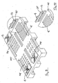
- FIG. 9 shows a pallet 115 with four holding means 13 with therein holding elements 14, wherein four different forms of a tongue and groove connections between the pallet 115 and holding means 13 are shown.
- the tongue and groove connections shown here have for example a rectangular elongated shape, a plurality of juxtaposed circular, diamond-shaped or triangular shapes. Other shapes are also conceivable.
Landscapes
- Engineering & Computer Science (AREA)
- Mechanical Engineering (AREA)
- Packaging Of Machine Parts And Wound Products (AREA)
Description
- Die Erfindung betrifft eine Transportsicherung für Wickelrollen, wobei die Transportsicherung folgendes aufweist:
- a) eine Palette,
- b) mindestens zwei Haltemittel, und
- c) zwei Stirnwände, wobei die Stirnwände im Wesentlichen senkrecht zu der Palette, auf zwei sich gegenüberliegenden Seiten der Palette und parallel zueinander angeordnet sind, wobei zwischen beiden Stirnwänden die Wickelrolle angeordnet ist und eine Längsachse der Wickelrolle senkrecht zu beiden Stirnwänden verläuft und
- d) die Haltemittel durch werkzeugloses Einstecken oder Einsetzen formschlüssig mit der Palette verbindbar und wieder davon entfernbar sind, und jede Stirnwand formschlüssig mit einem Haltemittel verbindbar und wieder davon entfernbar ist.
- Bekanntermaßen wird bahnförmiges Gut, insbesondere Folie aus Kunststoff, auf einen Wickelkern aufgewickelt. Im Sinne der vorliegenden Anmeldung wird die Kombination aus dem Wickelkern mit dem darauf befindlichen bahnförmigen Gut als Wickelrolle bezeichnet. Der Wickelkern besteht typischerweise aus einer Hülse aus Kunststoff oder einer starren Pappe. Um bei einem Transport die teilweise sehr hochwertigen und teuren Folien nicht zu beschädigen, wird der Wickelkern an seinen Stirnseiten mit Hilfe von so genannten Stirnwänden abgestützt, die bewirken, dass die Unterseite des aufgewickelten bahnförmigen Gutes im Abstand oberhalb des Bodens angeordnet ist. Dazu weisen die Stirnwände entweder in den Wickelkern axial vorstehende Lagerzapfen oder aber Lagerbohrungen auf, in die Lagerbuchsen eingesteckt werden, die wiederum in den Wickelkern eintreten. Die beiden Stirnwände bilden mit dem Wickelkern beziehungsweise der Wickelrolle einen Lagerverbund, der auf einer Palette angeordnet wird.
- Derartige Stirnwände werden beispielsweise in der
EP 0 753 469 B1 beschrieben, wobei diese Stirnwände jeweils aus einer rechteckigen Platte bestehen. Auf einer der Wickelrolle zugewandten Vorderseite dieser Platte sind ein Ringaufsatz und eine zentrale Einstecköffnung angeordnet. An den jeweils zwei sich gegenüberliegenden Rändern dieser Platte befinden sich senkrecht zu der Platte angeordnete Seitenflächen, wobei zwei der sich gegenüberliegenden Seitenflächen eine glatte Oberfläche aufweisen und die anderen zwei sich gegenüberliegenden Seitenflächen unterschiedlich strukturiert sind. Die vier Seitenflächen sind über abgerundete Ecken miteinander verbunden. Die erste der strukturierten Seitenflächen weist Riffelungen auf, welche derart ausgestaltet sind, dass bei einem Aufsetzen der Stirnwand auf einer Holzpalette Rutschfestigkeit verliehen wird. Die zweite der strukturierten Seitenflächen weist neben der Riffelung auch noch Mulden auf, die mit einer anderen Seitenwand des Lagerverbundes korrespondieren, sodass zwei Lagerverbunde aufeinander gestapelt werden können. - Typischerweise werden die Stirnwände mit dem dazwischen angeordneten Lagerverbund mit Transport- beziehungsweise Spannbändern auf der Palette befestigt. Zusätzlich ist meist vorgesehen, dass die Stirnwände mittels Kunststoff- oder Holzleisten, die mit der Palette verschraubt werden, gegen seitliches Verrutschen, also in Richtung der Längsachse des Wickelkerns gesichert werden. Dies erfordert individuelles, manuelles Arbeiten und ist daher aufwendig und teuer.
- In der
EP 1 705 134 A2 wird ein variables Transportsystem für bahnförmiges Gut beschrieben. Die Palette, auf der der Lagerverbund angebracht werden soll, ist zweigeteilt, sodass ein Abstand der beiden Palettenhälften an den Abstand zwischen den beiden Stirnwänden beziehungsweise an die Länge der Wickelrolle angepasst werden kann. Die beiden Palettenhälften sind über Balken miteinander verbunden, wobei die Balken je nach Abstand mehr oder weniger in Öffnungen der Palettenhälften hineinragen. Befinden sich die Palettenhälften an der richtigen Position, werden die Balken an der jeweiligen Palettenhälfte befestigt, sodass die Palettenhälften nicht weiter auseinander rutschen können. Zusätzlich wird ein Auseinanderschieben der Stirnwände während des Transports des Wickelkernes dadurch verhindert, dass diese mit Metall- oder Kunststoffriemen zusammengehalten werden. - Dieses Transportsystem lässt sich nicht mit gängigen Transportsystemen kombinieren, wodurch immer ein gesamtes neues Transportssystem angeschafft werden muss, welches mit hohen Anschaffungskosten verbunden ist. Ein weiterer Nachteil besteht darin, dass der Transport des Lagerverbundes auf den beiden Palettenhälften, wenn die beiden Palettenhälften auseinander geschoben sind, erschwert wird, da die Öffnung für die Einführung beispielsweise von Gabeln eines Gabelstaplers sehr weit auseinander liegen. Die Balken eignen sich nicht als Ablagefläche für die Gabeln eines Gabelstapler, da die Balken keine ausreichende Festigkeit aufweisen.
- Aufgrund der Größe der Paletten ist es schwierig, mittels dieser zweigeteilten Palette einen genauen Abstand für die Länge der Wickelrolle einzustellen.
- Eine weitere Transportsicherung für Wickelrollen ist aus der
EP 0 648 684 A1 bekannt. Diese Transportsicherung weist alle Merkmale des Oberbegriffs des Anspruchs 1 auf. - Der vorliegenden Erfindung liegt nunmehr die Aufgabe zugrunde eine zuverlässige, kostengünstige und einfache Transportsicherung des Lagerverbunds aus Wickelrolle und Stirnwänden auf einer Palette zur Verfügung zu stellen, wobei eine stabile Sicherung unterschiedlich langer Wickelrollen durch eine präzise Einstellbarkeit des Abstandes der beiden Stirnwände ermöglicht werden soll.
- Ausgehend von einer Transportsicherung der eingangs beschriebenen Art wird die zugrunde liegende Aufgabe dadurch gelöst, dass zwischen Haltemittel und Stirnwand ein Halteelement angeordnet ist, und dass die Stirnwand und das Haltemittel jeweils lösbar formschlüssig mit dem Halteelement verbunden sind, wobei die Stirnwand mittels des Halteelements in dem Haltemittel angebracht ist.
- Mittels dieses zusätzlichen Halteelements soll eine feinere Justierung des Abstandes zwischen den beiden Stirnwänden, also eine exakte Ausrichtung der Stirnwände zueinander ermöglicht werden. Das heißt, dass der Abstand zwischen den beiden sich gegenüberliegenden Stirnwänden möglichst in sehr kleinen Schritten änderbar ist und somit jede Länge einer Wickelrolle mittels der Transportsicherung transportiert werden kann.
- Aufgrund der Haltemittel kann auf die Befestigung der Stirnwände auf der Palette mittels aufwendig zu montierenden Verbindungs- und Hilfsmitteln wie beispielsweise verschraubten Kunststoff- oder Holzleisten verzichtet werden. Infolgedessen wird die Arbeitssicherheit verbessert und die Verletzungsgefahr reduziert. Hinzu kommt, dass die Anbringung der Stirnwände erheblich vereinfacht und zudem beschleunigt wird. Vorzugsweise bestehen die erfindungsgemäßen Haltemittel aus Kunststoff, sodass die hygienischen Umstände verbessert werden können.
- Die Haltemittel werden zunächst auf der Palette eingesteckt oder eingesetzt, sodass in Bezug auf eine Verschiebung parallel zu der Oberfläche der Palette ein formschlüssiger Verbund entsteht. Anschließend werden die Stirnwände mit der dazwischen angeordneten Wickelrolle senkrecht auf die Halteelemente und Haltemittel angebracht, wobei eine Längsachse der Wickelrolle senkrecht zu der Stirnwand und parallel zu der Palette angeordnet ist. Auch hier entsteht ein Formschlussverbund in Bezug auf eine Verschiebung der Stirnwand gegenüber dem jeweiligen Haltemittel.
- Nach dem Transport werden die Stirnwände typischerweise von den Haltemitteln beziehungsweise der Palette entnommen. Anschließend können auch die Haltemittel wieder von der Palette gelöst werden, wobei die Haltemittel vorzugsweise mehrfach verwendet werden können. Die Lagerung der Haltemittel sowie der Paletten nimmt durch die Entnahme der Haltemittel weniger Platz in Anspruch.
- Die Haltemittel können nicht nur mehrfach auf unterschiedlichen Paletten angeordnet werden, sondern es ist vorzugsweise vorgesehen, dass die Haltemittel an gängige Paletten angebracht werden können, sodass auf die Anschaffung spezieller Paletten verzichtet werden kann und somit Kosten eingespart werden können. Dadurch dass die Haltemittel sich wieder von der Palette lösen lassen, können auch unterschiedlich große Paletten eingesetzt werden.
- Damit die Montage sowie die Entnahme des Haltemittels von der Palette möglichst einfach durchführbar ist, ist in einer weiteren Ausgestaltung der Erfindung vorgesehen, dass das Haltemittel über eine Nut-Federverbindung und/oder eine Stift-Ausnehmung-Verbindung mit der Palette verbunden ist. Die Palettennut beziehungsweise Ausnahme befindet sich vorzugsweise in der Palette und die Feder beziehungsweise der Stift an einer der Palette zugewandten Seite des Haltemittels. Nichtsdestotrotz kann mittels dieser Verbindungsarten eine ausreichende Kraftübertragung stattfinden, sodass die Wickelrolle mit dem bahnförmigen Gut während des Transportes ausreichend gesichert ist und nicht beschädigt wird, das heißt, dass ein Schaukeln der Stirnwände in Richtung der Längsachse der Wickelrolle und somit eine Beschädigung der Folien-Schnittkanten vermieden wird.
- Im Sinne der vorliegenden Anmeldung kann die Nut-Federverbindung auch eine Kombination aus zwei Zahngeometrien sein.
- In konstruktiver Hinsicht ist es besonders vorteilhaft, wenn sich mehrere Paletten nuten oder Durchbrüche in einer Oberfläche der Palette befinden, wobei die Palettennuten vorzugsweise in regelmäßigen Abständen zueinander angeordnet sind. Die Anordnung mehrerer Palettennuten in der Palette erlaubt ein Transport unterschiedlich langer Wickelrollen mit derselben Palette, da die Haltemittel nach jedem Transport von der Palette gelöst und an einer anderen Position wieder eingesetzt werden können. Eine Position der Haltemittel auf der Palette kann also dem Abstand zwischen den beiden Stirnwänden entsprechend angepasst werden. Folglich braucht nur eine Standardgröße der Palette bereitgehalten werden. Hinzu kommt, dass dadurch der Transport der Palette standardisiert werden kann, da der Abstand beispielsweise zweier Gabeln eines Gabelstaplers immer gleich ausgerichtet bleiben kann und nicht ständig geändert werden muss.
- In einer Weiterentwicklung der Erfindung ist vorgesehen, dass das Haltemittel auf einer der Palette abgewandten Fläche mindestens eine Haltemittelnut aufweist, wobei die Haltemittelnut unter einem ersten Winkel zu der Längsachse der Wickelrolle angeordnet ist, wobei der Winkel vorzugsweise 45 Grad beträgt. Das Halteelement wird insbesondere in der Haltemittelnut angebracht, wobei das Halteelement vorzugsweise neben einem Nutboden zwei sich gegenüberliegende Nutwangen aufweist. Der Nutboden ist in einem gleichen Winkel zu der Längsachse der Wickelrolle angeordnet wie die Haltemittelnut in dem Haltemittel. Wohingegen die beiden Nutwangen des Halteelements vorzugsweise derart an dem Nutboden befestigt sind, dass diese mit ihrer jeweiligen horizontalen Längsachse parallel zu der Stirnwand und senkrecht zur Längsachse der Wickelrolle angeordnet sind. Folglich ist der Nutboden parallelogrammförmig ausgestaltet.
- Diese Anordnung der Haltemittelnut und somit des Halteelements weist den Vorteil auf, dass bei einer großen Verschiebung des Halteelements in der Haltemittelnut eine geringere Verschiebung der Nutwangen des Halteelements in eine Richtung senkrecht zu der Stirnwand und parallel zur Palette auftritt. Folglich können die Haltemittel derart eingestellt werden, dass bereits sehr geringe Unterschiede der Länge der Wickelrollen ausgeglichen werden können, das heißt, es ist eine sehr feinteilige Einstellung möglich. Dementsprechend kann auf Standardmaße bei den Wickelrollen verzichtet werden.
- Ferner wird vorgeschlagen, dass das Halteelement eine Befestigungszunge aufweist, die, auf ihrer dem Haltemittel zugewandten Seite, eine Zahnreihe aufweist, welche vorzugsweise mit einer weiteren in den Haltemittelnuten senkrecht zu einem Haltemittelnutverlauf angeordneten Zahnreihe korrespondiert und die beiden Zahnreihen eine Verzahnung bilden, wobei die Stirnwände vorzugsweise im installierten Zustand mit Ihrer Gewichtskraft die beiden Zahnreihen in Kontakt bringen. Das Halteelement lässt sich nun nicht mehr in eine Richtung senkrecht zu der Längsachse der Haltemittelnut verschieben. Durch die Positionierung des Haltemittels in den Nuten der Palette und die Verzahnung zwischen dem Halteelement und dem Haltemittel ist eine quasi stufenlose Anordnung der Stirnwände beziehungsweise eine Anordnung der Stirnwände mit einem Rastermaß von vorzugsweise 1,0 bis 10,0 mm, weiter vorzugsweise 1,5 bis 7,0 mm, weiter vorzugsweise zwischen 2,0 und 5,0 mm möglich, wodurch zwischen einer maximalen und einer minimalen Länge jede Länge einer Wickelrolle mit den Stirnwänden auf der Palette angebracht werden kann.
- Das Halteelement wird vorzugsweise derart in der Haltemittelnut eingebracht, dass eine Oberseite des Haltemittels, also eine der Stirnwand zugewandten Seite, auf einer Höhe mit der Oberseite des Nutbodens des Halteelements liegt, wodurch eine Verschiebung des Halteelements in eine Richtung senkrecht zu dem ersten Winkel durch die Nutwandungen der Haltemittelnut verhindert wird.
- Damit verhindert wird, dass die auf dem Halteelement befindliche Stirnwand nicht verrutschen kann, ist in einer Weiterentwicklung der Erfindung vorgesehen, dass das Halteelement auf seiner dem Haltemittel abgewandten Seite eine Halteelementnut aufweist, die so ausgeformt ist, dass die Stirnwände mit ihrer Tiefe in die Breite der Halteelementnut passen. Die Halteelementnut weist die beiden Nutwangen sowie den Nutzboden auf. Mittels dieser Anordnung wird verhindert, dass die Stirnwände in eine Richtung entlang der Längsachse parallel zu der Platte bewegt werden können.
- In einer weiteren Ausgestaltung der Erfindung ist vorgesehen, dass die Stirnwände an ihren Seitenflächen mindestens eine Rille zur Aufnahme eines Transportbandes aufweisen. Vorzugsweise wird das mindestens eine Transportband von der einen Stirnwand unter der Palette hindurch zu nächsten Stirnwand und dann wieder zu der ersten Stirnwand auf einer der Palette abgewandten Seite der Stirnwand vorbeigeführt. Mittels der Transportbänder kann ein Umkippen der Transportbänder in eine Richtung welche von der Wickelrolle wegführt verhindert werden, wodurch eine zusätzliche Sicherung der Stirnwände während des Transportes stattfindet.
- Alternativ oder zusätzlich kann vorgesehen sein, dass sich zwischen den sich gegenüberliegenden Stirnwänden an einer der Palette abgewandten Ecke der jeweiligen Stirnwand Stützstreben angeordnet sind. Die Stützstreben verhindern, dass die Seitenwände in die Richtung der Wickelrolle oder von dieser wegkippen können. Das heißt, dass mittels der Stützstreben die Seitenwände besser gestützt sind und somit eine ausreichende Halterung der Wickelrolle gewährleistet werden kann.
- Es sollen nicht nur die Haltemittel und/oder Halteelemente an die Länge der Wickelrolle angepasst werden können, sondern es ist erfindungsgemäß vorgesehen, dass die Stützstreben in ihrer Länge verstellbar sind.
- Die vorstehend beschriebene Erfindung wird nachfolgend anhand von Ausführungsbeispielen, die in den Figuren dargestellt werden, näher erläutert.
- Es zeigt:
- Fig. 1:
- eine Transportsicherung in einer ersten erfindungsgemäßen Ausführungsform,
- Fig. 2:
- eine Transportsicherung gemäß
Figur 1 , wobei Stützstreben zwischen Stirnwänden angeordnet sind, - Fig. 2a:
- eine Feder-Nut-Verbindung gemäß
Figur 2 in einer ersten Ausführungsform, - Fig. 2b:
- eine Feder-Nut-Verbindung gemäß
Figur 2 in einer zweiten Ausführungsform, - Fig. 3:
- einen Vertikalschnitt der Transportsicherung gemäß
Figur 1 , - Fig. 4:
- eine Stirnwand mit dem erfindungsgemäßen Haltemittel gemäß
Figur 1 und einem Halteelement, - Fig. 5:
- eine Rückseite der Stirnwand, des Haltemittels sowie des Halteelements gemäß
Figur 4 , - Fig. 6:
- eine Seitenansicht des Stirnwand, des Haltemittels sowie des Halteelements gemäß
Figur 4 , - Fig. 7:
- eine Ansicht des Haltemittels in seiner ersten Ausführungsform mit einem erfindungsgemäßen Halteelement gemäß
Figur 4 , - Fig. 7a:
- eine Ansicht des Haltemittels gemäß
Figur 4 in einer alternativen Ausführungsform, - Fig. 8:
- eine Schnittansicht des Haltemittels und des erfindungsgemäßen Halteelements gemäß
Figur 7 , - Fig. 9:
- eine Ansicht einer Palette einer Transportsicherung mit dem Haltemittel und dem dazugehörigen erfindungsgemäßen Halteelement gemäß
Figur 7 und - Fig. 10:
- eine Vergrößerung eines Ausschnitts der Palette und des Haltemittels gemäß
Figur 9 . - In der
Figur 1 wird eine erfindungsgemäße Transportsicherung 1 für Wickelrollen 2 dargestellt, wobei die Wickelrollen 2 einen Wickelkern 3 gemäßFigur 3 mit einem rohrförmigen Durchschnitt sowie bahnförmiges Gut 4 aufweisen. Die Wickelrolle 2 wird mittels Lagerbuchsen 5 an zwei Stirnwänden 6 befestigt. Beide Stirnwände 6 weisen einen Durchbruch 7 in Form einer Zentrierbohrung auf, durch welchen die Lagerbuchsen 5 in eine Innenseite 8 gemäßFigur 3 des Wickelkerns 3 geführt werden. Eine Längsachse 9 der Wickelrolle 2 ist horizontal angeordnet und entspricht einer Längsachse des Durchbruchs 7. - Die Stirnwände 6 weisen jeweils eine zueinander ausgerichtete Vorderseite 10 und eine von der Wickelrolle 2 abgewandte Rückseite 11 auf. Die Wickelrolle 2 mit den beiden Stirnwänden 6 bildet einen Lagerverbund 12 der mittels vier Haltemitteln 13 mit vier dazugehörigen Halteelementen 14 gemäß
Figur 7 auf einer Palette 15 angebracht wird. Die Palette 15 ist horizontal angeordnet und weist mehrere Palettennuten 16 auf. - Mittels Transportbändern 17 werden die Stirnwände 6 zusätzlich stabilisiert. Die Transportbänder 17 führen unter der Palette 15 durch an den beiden Stirnwänden 6 entlang über die Wickelrolle 2, wobei die Transportbänder 17 die Wickelrolle 2 nicht berühren.
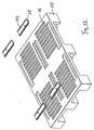
- Alternativ ist in
Figur 2 vorgesehen, dass zusätzlich zu den Transportbändern 17 Stützstreben 46 zwischen den beiden sich gegenüberliegenden Stirnwänden 6 angeordnet sind. Die jeweilige Stützstrebe 46 ist dreiteilig, das heißt, jede Stützstrebe 46 wird von zwei äußeren Elementen 47, 48 und einem mittleren Element 49 gebildet, wobei die beiden äußeren Elemente 47, 48 in dem mittleren Element 49 angeordnet und mittels einer Feder-Nut-Verbindung 50 verbunden sind. Mit Hilfe der Feder-Nut-Verbindung 50 kann eine Länge der Stützstreben 46 an einen Abstand zwischen den beiden sich gegenüberliegenden Stirnflächen 6 angepasst werden. - Die
Figur 2a stellt eine Vergrößerung der Verbindung zwischen dem mittleren Element 49 und dem äußeren Element 47 dar. Die Feder-Nut-Verbindung 50 befindet sich auf einer von der Palette 15 abgewandten Seite der Stützstreben 46. Alternativ kann eine Feder-Nut-Verbindung 51 gemäßFigur 2b auch an zwei sich gegenüberliegenden vertikalen Seiten 52, 53 der Stützstreben 46 angeordnet sein. DieFigur 3 zeigt einen Vertikalschnitt entlang der Längsachse 9 der Wickelrolle 2. Der Wickelkern 3 mit dem darauf befindlichen bahnförmigen Gut 4, ist mittels der Lagerbuchsen 5 an den Stirnwänden 6 befestigt, sodass zwischen der Palette 15 und dem bahnförmigen Gut 4 ein Abstand A besteht. Die Längsachse 9 des Wickelkerns 3 beziehungsweise der Wickelrolle 2 verläuft horizontal und ist identisch mit einer Längsachse der Lagerbuchsen 5. Weiterhin ist sichtbar, dass die beiden Stirnwände 6 an zwei sich gegenüberliegenden Seiten der Wickelrolle 2 senkrecht zur Palette 15 angebracht sind. - In der
Figur 4 wird die der Wickelrolle zugewandte Vorderseite 10 einer der beiden Stirnwände 6 dargestellt. In der Stirnwand 6 befindet sich der Durchbruch 7, durch welchen normalerweise die Lagerbuchse geführt wird. Die Stirnwand 6 weist vier Seitenflächen auf, welche senkrecht zu der Stirnwand 6 angeordnet sind. In der oberen Seitenfläche 18 befinden sich Erhebungen 19 und Mulden 20, eine sogenannte Stapelarretierung, die mit einer weiteren Stapelarretierung, also mit Erhebungen und Mulden, einer hier nicht dargestellten Stirnwand korrespondiert, sodass die hier nicht dargestellte Stirnwand auf der hier dargestellten Stirnwand 6 angeordnet werden könnte. Auf den Erhebungen 19 sowie auf einer unteren Seitenfläche 21 befindet sich eine Rifflung 22 in Form einer Anti-Rutsch-Rifflung, welche verhindert, dass die Stirnwände 6 in eine Richtung senkrecht zu der Längsachse 9 der Wickelrolle 2 verschoben werden kann. Die Stirnwand 6 wird mittels des Halteelements 14 in dem Haltemittel 13 angebracht, wobei sowohl das Halteelement 14 als auch das Haltemittel 13 normalerweise bereits auf der Palette angeordnet sind. - Die
Figur 5 zeigt die Rückseite 11 der Stirnwand 6 gemäßFigur 4 und das Haltemittel 13 sowie das Halteelement 14. Die Rückseite 11 weist horizontale Rippen 23 und vertikale Rippen 24 auf, sodass die Stirnwand 6 trotz ihres geringen Gewichts eine ausreichende Stabilität aufweist. An dem Haltemittel 13 befindet sich eine Feder 25, die mit der Palettennut 16 gemäßFigur 1 in der Palette 15 korrespondiert und einen Formschluss bildet. - Die
Figur 6 zeigt eine Seitenansicht der Stirnwand 6, des Haltemittels 13 und des Halteelements 14 gemäßFigur 4 , wobei die Stirnwand 6 eine Tiefe T aufweist. - In der
Figur 7 wird das erfindungsgemäße Haltemittel 13 mit dem installierten erfindungsgemäßen Halteelement 14 dargestellt. - Das Haltemittel 13 weist an seiner der hier nicht dargestellten Palette abgewandten Oberseite 26 zwei gekreuzte Haltemittelnuten 27, 28 auf, welche von Nutwandungen 29 und einem Nutgrund 30 gebildet werden. Ein hier nicht dargestellter Winkel zwischen einem ersten Haltemittelnutverlauf 31 oder einem zweiten Haltemittelnutverlauf 32 und der hier nicht dargestellten Längsachse der Wickelrolle beträgt 45 Grad beziehungsweise 135 Grad. Folglich beträgt ein Winkel α zwischen dem ersten Haltemittelnutverlauf 31 und dem zweiten Haltemittelnutverlauf 32 90 Grad.
- Das Halteelement 14 kann entweder in der ersten Haltemittelnut 27 oder in die zweite Haltemittelnut 28 angeordnet werden, wobei das Halteelement 14 eine Halteelementnut 33 mit einem Nutboden 34 und zwei Nutwangen 35 aufweist. Eine Längsachse 36 der Nutwangen 35 ist senkrecht zu der hier nicht dargestellten Längsachse der Wickelrolle angeordnet, sodass auch die hier nicht dargestellten Stirnwände senkrecht zur Längsachse der Wickelrolle in dem Halteelement 14 angeordnet werden können. Infolge dieser Anordnung ist eine Oberseite 37 des Nutbodens 34 parallelogrammförmig. Eine Breite B zwischen den Nutwangen 35 entspricht der Tiefe T der Stirnwand 6 gemäß
Figur 6 . - Im eingebauten Zustand des Halteelements 14, weisen die dem Haltemittel 13 abgewandte Oberseite 37 des Nutbodens 34 und die Nutwandungen 29 des Haltemittels 13 eine gleiche Höhe H auf.
- In dem Nutboden 34 des Halteelements 14 befindet sich eine Befestigungszunge 39, die im nicht installierten Zustand in die Halteelementnut 33 herausragt und an seiner dem Haltemittel 13 zugewandten Seite 40 gemäß
Figur 8 eine Zahnreihe 41 aufweist, die mit einer weiteren Zahnreihe 42 in dem Haltemittel 13 korrespondieren. Die Zahnreihe 42 ist senkrecht zu dem beiden Haltemittelverläufen 31, 32 angeordnet. Die Zahnreihe 41 des Halteelements 14 bildet mit der Zahnreihe 42 des Haltemittels 13 eine Verzahnung 38. - In der
Figur 7a wird ein alternatives Haltemittel 52 dargestellt, welches sich in der Hinsicht von dem Haltemittel 13 gemäßFigur 7 unterscheidet, dass sich auf einer Oberfläche 53 des Haltemittels 52 Gummieinlagen 54 befinden, welche einen zusätzlichen Schutz vor einem Verrutschen der Stirnwände senkrecht zu der Längsachse der Wickelrolle oder in eine Richtung entlang der Längsachse der Wickelrolle bieten. - Die
Figur 8 zeigt einen Vertikalschnitt des Haltemittels 13 sowie des Halteelements 14 entlang des ersten Haltemittelnutverlaufs 31. Aus dieser geht hervor, dass die Zahnreihe 41 in der Befestigungszunge 39 des Halteelements 14 in die Zahnreihe 42 des Haltemittels 13 eingreifen kann und beide Zahnreihen 41, 42 eine Verzahnung 46 bilden, wenn die hier nicht dargestellte Stirnwand auf das Halteelement 14 platziert wird. Eine Bewegung des Halteelements 14 in dem Haltemittel 13 wird vollständig verhindert und folglich eine Bewegung der Stirnwände in eine Richtung senkrecht zu der Längsachse der Wickelrolle unterbunden. - In dem dargestellten Zustand befindet sich die Zahnreihe 41 nicht vollständig in der Zahnreihe 42. Allerdings kann die Befestigungszunge 39 noch weiter angehoben werden, sodass die Zahnreihe 41 vollständig aus der Zahnreihe 42 hervorsteht, wodurch das Halteelement 14 entlang des Haltemittelnutverlaufes 31 verschoben werden kann. Dadurch können verschiedene Abstände zwischen den beiden sich gegenüberliegenden Stirnwänden eingestellt werden.
- Die
Figur 9 zeigt eine Palette 115 mit vier Haltemitteln 13 mit darin befindlichen Halteelementen 14, wobei vier verschiedene Formen einer Nut-Feder-Verbindungen zwischen Palette 115 und Haltemittel 13 dargestellt sind. Die hier dargestellten Nut-Feder-Verbindungen haben beispielsweise eine rechteckige längliche Form, mehrere nebeneinander angeordnete kreisförmige, rautenförmige oder dreieckige Formen. Andere Formen sind allerdings auch denkbar. Bei allen vorgegeben Formen befinden sich die Federn 25 an einer der Palette 115 zugewandten Unterseite 43 des Haltemittels 13 und die dazugehörigen Nuten 16, 116, 216, 316 sind in der Palette 115 angeordnet. Durch eine Aneinanderreihung der Nuten 16, 116, 216, 316 in Längsrichtung der Wickelrolle in der Palette 115 ist eine erfindungsgemäße Ausrichtung der Stirnwände möglich, wobei eine feinere Justierung mittels des Halteelements 14 in dem Haltemittel 13 stattfindet. - In der
Figur 10 wird die Nut-Feder-Verbindung zwischen dem Haltemittel 13 und der Palette 115 noch einmal vergrößert dargestellt. - Die verschiedenen Merkmale können je einzeln für sich oder zu mehreren in beliebigen Kombinationen bei Varianten der Erfindung verwirklicht sein.
-
- T
- Tiefe
- A
- Abstand
- H
- Höhe
- B
- Breite
- α
- Winkel
- 1
- Transportsicherung
- 2
- Wickelrolle
- 3
- Wickelkern
- 4
- Gut
- 5
- Lagerbuchse
- 6
- Stirnwände
- 7
- Durchbruch
- 8
- Innenseite
- 9
- Längsachse
- 10
- Vorderseite
- 11
- Rückseite
- 12
- Lagerverbund
- 13
- Haltemittel
- 14
- Halteelement
- 15, 115
- Palette
- 16, 116, 216, 316
- Palettennut
- 17
- Transportband
- 18
- Seitenfläche
- 19
- Erhebung
- 20
- Mulde
- 21
- Seitenfläche
- 22
- Rifflung
- 23
- Rippe
- 24
- Rippe
- 25
- Feder
- 26
- Oberseite
- 27
- Haltemittelnut
- 28
- Haltemittelnut
- 29
- Nutwandung
- 30
- Nutgrund
- 31
- Haltemittelnutverlauf
- 32
- Haltemittelnutverlauf
- 33
- Halteelementnut
- 34
- Nutboden
- 35
- Notwangen
- 36
- Längsachse
- 37
- Oberseite
- 38
- Verzahnung
- 39
- Befestigungszunge
- 40
- Seite
- 41
- Zahnreihe
- 42
- Zahnreihe
- 43
- Unterseite
- 44
- Längsachse
- 45
- Zahnelement
- 46
- Stützstreben
- 47
- äußeres Element
- 48
- äußeres Element
- 49
- mittleres Element
- 50
- Feder-Nut-Verbindung
- 51
- Feder-Nut-Verbindung
- 52
- Haltemittel
- 53
- Oberfläche
- 54
- Gummieinlagen
Claims (9)
- Transportsicherung (1) für Wickelrollen (2) aufweisend:a) eine Palette (15, 115),b) mindestens zwei Haltemittel (13), undc) zwei Stirnwände (6), wobei die Stirnwände (6) im Wesentlichen senkrecht zu der Palette (15, 115), auf zwei sich gegenüberliegenden Seiten der Palette (15, 115) und parallel zueinander angeordnet sind, wobei zwischen beiden Stirnwänden (6) die Wickelrolle (2) angeordnet ist und eine Längsachse (9) der Wickelrolle (2) senkrecht zu beiden Stirnwänden (6) verläuft, undd) die Haltemittel (13) durch werkzeugloses Einstecken oder Einsetzen formschlüssig mit der Palette (15, 115) verbindbar und wieder davon entfernbar sind, und jede Stirnwand (6) formschlüssig mit einem Haltemittel (13) verbindbar und wieder davon entfernbar ist,dadurch gekennzeichnet, dass
zwischen Haltemittel (13) und Stirnwand (6) ein Halteelement (14) angeordnet ist, und dass die Stirnwand (6) und das Haltemittel (13) jeweils lösbar formschlüssig mit dem Halteelement (14) verbunden sind, wobei die Stirnwand (6) mittels des Halteelements (14) in dem Haltemittel (13) angebracht ist. - Transportsicherung (1) nach Anspruch 1, dadurch gekennzeichnet, dass das Haltemittel (13) über eine Nut-Federverbindung und/oder eine Stift-Ausnehmung-Verbindung mit der Palette (15, 115) verbunden ist.
- Transportsicherung (1) nach mindestens einem der Ansprüche 1 oder 2, dadurch gekennzeichnet, dass die Palette (15, 115) in einer Oberfläche mehrere Palettennuten (16, 116, 216, 316) oder Durchbrüche aufweist.
- Transportsicherung (1) nach einem der Ansprüche 1 bis 3, dadurch gekennzeichnet, dass das Haltemittel (13) auf einer der Palette (15, 115) abgewandten Fläche mindestens eine Haltemittelnut (27, 28) aufweist, wobei die Haltemittelnut (27, 28) unter einem ersten Winkel zu der Längsachse (9) der Wickelrolle (2) angeordnet ist, wobei der Winkel vorzugsweise 45 Grad beträgt.
- Transportsicherung (1) nach einem der Ansprüche 1 bis 4, dadurch gekennzeichnet, dass das Halteelement (14) eine Befestigungszunge (39)
aufweist, die, auf ihrer dem Haltemittel (13) zugewandten Seite (40), eine Zahnreihe (41) aufweist, welche vorzugsweise mit einer weiteren in der Haltemittelnut (27, 28) senkrecht zu einem Haltemittelnutverlauf (31, 32) angeordneten Zahnreihe (42) korrespondiert und die beiden Zahnreihen (41, 42) eine Verzahnung (38) bilden, wobei die Stirnwände (6) vorzugsweise im installierten Zustand mit Ihrer Gewichtskraft die beiden Zahnreihen (41, 42) in Kontakt bringen. - Transportsicherung (1) nach mindestens einem der Ansprüche 1 bis 5, dadurch gekennzeichnet, dass das Halteelement (14) auf seiner dem Haltemittel (13) abgewandten Seite eine Halteelementnut (33) aufweist, die so ausgeformt ist, dass die Stirnwände (6) mit ihrer Tiefe (T) in die Breite (B) der Halteelementnut passen.
- Transportsicherung (1) nach einem der Ansprüch 1 bis 6, dadurch gekennzeichnet, dass die Stirnwände (6) an ihren Seitenflächen mindestens eine Rille zur Aufnahme eines Transportbandes (17) aufweisen.
- Transportsicherung nach einem der Ansprüche 1 bis 7, dadurch gekennzeichnet, dass an den der Palette (15) abgewandten Ecken der Stirnwände (6) zwischen den Stirnwänden (6) Stützstreben (46) angeordnet sind.
- Transportsicherung nach Anspruch 8, dadurch gekennzeichnet, dass die Stützstreben (46) in ihrer Länge verstellbar sind.
Priority Applications (1)
| Application Number | Priority Date | Filing Date | Title |
|---|---|---|---|
| EP14162558.2A EP2927157B1 (de) | 2014-03-31 | 2014-03-31 | Transportsicherung für Wickelrollen |
Applications Claiming Priority (1)
| Application Number | Priority Date | Filing Date | Title |
|---|---|---|---|
| EP14162558.2A EP2927157B1 (de) | 2014-03-31 | 2014-03-31 | Transportsicherung für Wickelrollen |
Publications (2)
| Publication Number | Publication Date |
|---|---|
| EP2927157A1 EP2927157A1 (de) | 2015-10-07 |
| EP2927157B1 true EP2927157B1 (de) | 2016-05-11 |
Family
ID=50424046
Family Applications (1)
| Application Number | Title | Priority Date | Filing Date |
|---|---|---|---|
| EP14162558.2A Not-in-force EP2927157B1 (de) | 2014-03-31 | 2014-03-31 | Transportsicherung für Wickelrollen |
Country Status (1)
| Country | Link |
|---|---|
| EP (1) | EP2927157B1 (de) |
Families Citing this family (1)
| Publication number | Priority date | Publication date | Assignee | Title |
|---|---|---|---|---|
| IT202100000305U1 (it) | 2021-01-25 | 2022-07-25 | Lucy Plast S P A | Elemento di supporto per una bobina |
Family Cites Families (7)
| Publication number | Priority date | Publication date | Assignee | Title |
|---|---|---|---|---|
| FR2711112B1 (fr) * | 1993-10-13 | 1995-12-15 | Rhone Poulenc Films | Dispositif de positionnement de bobine et procédé d'emballage utilisant ce dispositif. |
| DE19524954A1 (de) | 1995-07-08 | 1997-01-09 | Hoechst Ag | Stirnwand aus formbarem Material |
| JP4753179B2 (ja) * | 2003-09-11 | 2011-08-24 | 三甲株式会社 | 巻回物包装体、巻回物包装用端壁および巻回物包装体の組立方法 |
| ITMI20050472A1 (it) | 2005-03-22 | 2006-09-23 | Lucy Plast S P A | Sistema di trasporto e stoccaggio per bobine |
| US7699167B2 (en) * | 2007-07-13 | 2010-04-20 | Badger Plug Company | Rolled goods handler |
| JP5493174B2 (ja) * | 2010-08-09 | 2014-05-14 | 日東電工株式会社 | 収容箱 |
| JP6146065B2 (ja) * | 2012-03-27 | 2017-06-14 | キョーラク株式会社 | ロール体用コンテナ |
-
2014
- 2014-03-31 EP EP14162558.2A patent/EP2927157B1/de not_active Not-in-force
Also Published As
| Publication number | Publication date |
|---|---|
| EP2927157A1 (de) | 2015-10-07 |
Similar Documents
| Publication | Publication Date | Title |
|---|---|---|
| EP3094568B1 (de) | Behälter für den transport von waren und vorrichtung zur unterteilung eines solchen behälters | |
| EP2878548B1 (de) | Palette | |
| EP2545813B9 (de) | Warenvorschubeinsatz für ein Warenvorschubsystem | |
| EP1754897B1 (de) | Lagerungsvorrichtung | |
| EP3303731B1 (de) | Gerüstbodenelement, insbesondere für ein baugerüst | |
| EP2927157B1 (de) | Transportsicherung für Wickelrollen | |
| DE202016002839U1 (de) | Verpackungspapierdispenservorrichtung | |
| EP2505512B1 (de) | Transporteinheit und Verfahren zum Bilden einer Transporteinheit | |
| DE102016006237A1 (de) | Kappenanordnung zur Halterung wenigstens einer Federleiste einer Unterfederung für ein Möbel oder einen Rahmen und zugehörige Federleiste | |
| DE202019101370U1 (de) | Ladungsträger mit Wandelementen | |
| DE2523964C2 (de) | Traggestell zum Transport der Gerüstelemente von Baugerüsten | |
| DE102017111334B3 (de) | Boxensystem | |
| DE102014011070B4 (de) | Palette | |
| EP3241471B1 (de) | Verpackungspapierdispenservorrichtung | |
| EP0615912B1 (de) | Transport- und Verpackungsbehältnis | |
| AT14826U1 (de) | Palette | |
| EP3047168B1 (de) | Stapelhilfe für ringe mit unterschiedlichem durchmesser sowie verfahren zum stapeln von grosswälzlagerringen | |
| EP2226272A2 (de) | Regalsystem | |
| DE202008011483U1 (de) | Rollenhalter | |
| DE202012104733U1 (de) | Vorrichtung zur zumindest teilweisen Verkleidung einer Palette | |
| DE202011001890U1 (de) | Rollenkernstandfuß | |
| DE202015106493U1 (de) | Absperrvorrichtung | |
| EP3290352A1 (de) | Sicherungsstreifen und verfahren zur sicherung eines transportgutes | |
| DE19524388A1 (de) | Palettensystem | |
| DE4334330A1 (de) | Vorrichtung für das Abziehen eines Blattes von einem Blattstapel |
Legal Events
| Date | Code | Title | Description |
|---|---|---|---|
| PUAI | Public reference made under article 153(3) epc to a published international application that has entered the european phase |
Free format text: ORIGINAL CODE: 0009012 |
|
| 17P | Request for examination filed |
Effective date: 20150120 |
|
| AK | Designated contracting states |
Kind code of ref document: A1 Designated state(s): AL AT BE BG CH CY CZ DE DK EE ES FI FR GB GR HR HU IE IS IT LI LT LU LV MC MK MT NL NO PL PT RO RS SE SI SK SM TR |
|
| AX | Request for extension of the european patent |
Extension state: BA ME |
|
| GRAP | Despatch of communication of intention to grant a patent |
Free format text: ORIGINAL CODE: EPIDOSNIGR1 |
|
| RIC1 | Information provided on ipc code assigned before grant |
Ipc: B65D 85/66 20060101AFI20151020BHEP Ipc: B65D 19/44 20060101ALN20151020BHEP |
|
| INTG | Intention to grant announced |
Effective date: 20151104 |
|
| RBV | Designated contracting states (corrected) |
Designated state(s): AL AT BE BG CH CY CZ DE DK EE ES FI FR GB GR HR HU IE IS IT LI LT LU LV MC MK MT NL NO PL PT RO RS SE SI SK SM TR |
|
| RIC1 | Information provided on ipc code assigned before grant |
Ipc: B65D 19/44 20060101ALN20151222BHEP Ipc: B65D 85/66 20060101AFI20151222BHEP |
|
| INTG | Intention to grant announced |
Effective date: 20160114 |
|
| GRAS | Grant fee paid |
Free format text: ORIGINAL CODE: EPIDOSNIGR3 |
|
| GRAA | (expected) grant |
Free format text: ORIGINAL CODE: 0009210 |
|
| AK | Designated contracting states |
Kind code of ref document: B1 Designated state(s): AL AT BE BG CH CY CZ DE DK EE ES FI FR GB GR HR HU IE IS IT LI LT LU LV MC MK MT NL NO PL PT RO RS SE SI SK SM TR |
|
| REG | Reference to a national code |
Ref country code: GB Ref legal event code: FG4D Free format text: NOT ENGLISH |
|
| REG | Reference to a national code |
Ref country code: CH Ref legal event code: EP |
|
| REG | Reference to a national code |
Ref country code: AT Ref legal event code: REF Ref document number: 798472 Country of ref document: AT Kind code of ref document: T Effective date: 20160515 |
|
| REG | Reference to a national code |
Ref country code: IE Ref legal event code: FG4D Free format text: LANGUAGE OF EP DOCUMENT: GERMAN |
|
| REG | Reference to a national code |
Ref country code: DE Ref legal event code: R096 Ref document number: 502014000754 Country of ref document: DE |
|
| REG | Reference to a national code |
Ref country code: LT Ref legal event code: MG4D |
|
| REG | Reference to a national code |
Ref country code: NL Ref legal event code: MP Effective date: 20160511 |
|
| PG25 | Lapsed in a contracting state [announced via postgrant information from national office to epo] |
Ref country code: LT Free format text: LAPSE BECAUSE OF FAILURE TO SUBMIT A TRANSLATION OF THE DESCRIPTION OR TO PAY THE FEE WITHIN THE PRESCRIBED TIME-LIMIT Effective date: 20160511 Ref country code: NL Free format text: LAPSE BECAUSE OF FAILURE TO SUBMIT A TRANSLATION OF THE DESCRIPTION OR TO PAY THE FEE WITHIN THE PRESCRIBED TIME-LIMIT Effective date: 20160511 Ref country code: FI Free format text: LAPSE BECAUSE OF FAILURE TO SUBMIT A TRANSLATION OF THE DESCRIPTION OR TO PAY THE FEE WITHIN THE PRESCRIBED TIME-LIMIT Effective date: 20160511 Ref country code: NO Free format text: LAPSE BECAUSE OF FAILURE TO SUBMIT A TRANSLATION OF THE DESCRIPTION OR TO PAY THE FEE WITHIN THE PRESCRIBED TIME-LIMIT Effective date: 20160811 |
|
| PG25 | Lapsed in a contracting state [announced via postgrant information from national office to epo] |
Ref country code: PT Free format text: LAPSE BECAUSE OF FAILURE TO SUBMIT A TRANSLATION OF THE DESCRIPTION OR TO PAY THE FEE WITHIN THE PRESCRIBED TIME-LIMIT Effective date: 20160912 Ref country code: SE Free format text: LAPSE BECAUSE OF FAILURE TO SUBMIT A TRANSLATION OF THE DESCRIPTION OR TO PAY THE FEE WITHIN THE PRESCRIBED TIME-LIMIT Effective date: 20160511 Ref country code: ES Free format text: LAPSE BECAUSE OF FAILURE TO SUBMIT A TRANSLATION OF THE DESCRIPTION OR TO PAY THE FEE WITHIN THE PRESCRIBED TIME-LIMIT Effective date: 20160511 Ref country code: LV Free format text: LAPSE BECAUSE OF FAILURE TO SUBMIT A TRANSLATION OF THE DESCRIPTION OR TO PAY THE FEE WITHIN THE PRESCRIBED TIME-LIMIT Effective date: 20160511 Ref country code: RS Free format text: LAPSE BECAUSE OF FAILURE TO SUBMIT A TRANSLATION OF THE DESCRIPTION OR TO PAY THE FEE WITHIN THE PRESCRIBED TIME-LIMIT Effective date: 20160511 Ref country code: GR Free format text: LAPSE BECAUSE OF FAILURE TO SUBMIT A TRANSLATION OF THE DESCRIPTION OR TO PAY THE FEE WITHIN THE PRESCRIBED TIME-LIMIT Effective date: 20160812 Ref country code: HR Free format text: LAPSE BECAUSE OF FAILURE TO SUBMIT A TRANSLATION OF THE DESCRIPTION OR TO PAY THE FEE WITHIN THE PRESCRIBED TIME-LIMIT Effective date: 20160511 |
|
| PG25 | Lapsed in a contracting state [announced via postgrant information from national office to epo] |
Ref country code: IT Free format text: LAPSE BECAUSE OF FAILURE TO SUBMIT A TRANSLATION OF THE DESCRIPTION OR TO PAY THE FEE WITHIN THE PRESCRIBED TIME-LIMIT Effective date: 20160511 |
|
| PG25 | Lapsed in a contracting state [announced via postgrant information from national office to epo] |
Ref country code: EE Free format text: LAPSE BECAUSE OF FAILURE TO SUBMIT A TRANSLATION OF THE DESCRIPTION OR TO PAY THE FEE WITHIN THE PRESCRIBED TIME-LIMIT Effective date: 20160511 Ref country code: CZ Free format text: LAPSE BECAUSE OF FAILURE TO SUBMIT A TRANSLATION OF THE DESCRIPTION OR TO PAY THE FEE WITHIN THE PRESCRIBED TIME-LIMIT Effective date: 20160511 Ref country code: SK Free format text: LAPSE BECAUSE OF FAILURE TO SUBMIT A TRANSLATION OF THE DESCRIPTION OR TO PAY THE FEE WITHIN THE PRESCRIBED TIME-LIMIT Effective date: 20160511 Ref country code: DK Free format text: LAPSE BECAUSE OF FAILURE TO SUBMIT A TRANSLATION OF THE DESCRIPTION OR TO PAY THE FEE WITHIN THE PRESCRIBED TIME-LIMIT Effective date: 20160511 Ref country code: RO Free format text: LAPSE BECAUSE OF FAILURE TO SUBMIT A TRANSLATION OF THE DESCRIPTION OR TO PAY THE FEE WITHIN THE PRESCRIBED TIME-LIMIT Effective date: 20160511 |
|
| REG | Reference to a national code |
Ref country code: DE Ref legal event code: R097 Ref document number: 502014000754 Country of ref document: DE |
|
| PG25 | Lapsed in a contracting state [announced via postgrant information from national office to epo] |
Ref country code: SM Free format text: LAPSE BECAUSE OF FAILURE TO SUBMIT A TRANSLATION OF THE DESCRIPTION OR TO PAY THE FEE WITHIN THE PRESCRIBED TIME-LIMIT Effective date: 20160511 Ref country code: PL Free format text: LAPSE BECAUSE OF FAILURE TO SUBMIT A TRANSLATION OF THE DESCRIPTION OR TO PAY THE FEE WITHIN THE PRESCRIBED TIME-LIMIT Effective date: 20160511 |
|
| PLBE | No opposition filed within time limit |
Free format text: ORIGINAL CODE: 0009261 |
|
| STAA | Information on the status of an ep patent application or granted ep patent |
Free format text: STATUS: NO OPPOSITION FILED WITHIN TIME LIMIT |
|
| 26N | No opposition filed |
Effective date: 20170214 |
|
| PG25 | Lapsed in a contracting state [announced via postgrant information from national office to epo] |
Ref country code: SI Free format text: LAPSE BECAUSE OF FAILURE TO SUBMIT A TRANSLATION OF THE DESCRIPTION OR TO PAY THE FEE WITHIN THE PRESCRIBED TIME-LIMIT Effective date: 20160511 |
|
| REG | Reference to a national code |
Ref country code: DE Ref legal event code: R119 Ref document number: 502014000754 Country of ref document: DE |
|
| REG | Reference to a national code |
Ref country code: CH Ref legal event code: PL |
|
| PG25 | Lapsed in a contracting state [announced via postgrant information from national office to epo] |
Ref country code: MC Free format text: LAPSE BECAUSE OF FAILURE TO SUBMIT A TRANSLATION OF THE DESCRIPTION OR TO PAY THE FEE WITHIN THE PRESCRIBED TIME-LIMIT Effective date: 20160511 |
|
| REG | Reference to a national code |
Ref country code: IE Ref legal event code: MM4A |
|
| REG | Reference to a national code |
Ref country code: FR Ref legal event code: ST Effective date: 20171130 |
|
| PG25 | Lapsed in a contracting state [announced via postgrant information from national office to epo] |
Ref country code: FR Free format text: LAPSE BECAUSE OF NON-PAYMENT OF DUE FEES Effective date: 20170331 Ref country code: LU Free format text: LAPSE BECAUSE OF NON-PAYMENT OF DUE FEES Effective date: 20170331 Ref country code: DE Free format text: LAPSE BECAUSE OF NON-PAYMENT OF DUE FEES Effective date: 20171003 |
|
| PG25 | Lapsed in a contracting state [announced via postgrant information from national office to epo] |
Ref country code: LI Free format text: LAPSE BECAUSE OF NON-PAYMENT OF DUE FEES Effective date: 20170331 Ref country code: IE Free format text: LAPSE BECAUSE OF NON-PAYMENT OF DUE FEES Effective date: 20170331 Ref country code: CH Free format text: LAPSE BECAUSE OF NON-PAYMENT OF DUE FEES Effective date: 20170331 |
|
| REG | Reference to a national code |
Ref country code: BE Ref legal event code: MM Effective date: 20170331 |
|
| PG25 | Lapsed in a contracting state [announced via postgrant information from national office to epo] |
Ref country code: BE Free format text: LAPSE BECAUSE OF NON-PAYMENT OF DUE FEES Effective date: 20170331 |
|
| PG25 | Lapsed in a contracting state [announced via postgrant information from national office to epo] |
Ref country code: MT Free format text: LAPSE BECAUSE OF FAILURE TO SUBMIT A TRANSLATION OF THE DESCRIPTION OR TO PAY THE FEE WITHIN THE PRESCRIBED TIME-LIMIT Effective date: 20160511 |
|
| PG25 | Lapsed in a contracting state [announced via postgrant information from national office to epo] |
Ref country code: AL Free format text: LAPSE BECAUSE OF FAILURE TO SUBMIT A TRANSLATION OF THE DESCRIPTION OR TO PAY THE FEE WITHIN THE PRESCRIBED TIME-LIMIT Effective date: 20160511 |
|
| GBPC | Gb: european patent ceased through non-payment of renewal fee |
Effective date: 20180331 |
|
| PG25 | Lapsed in a contracting state [announced via postgrant information from national office to epo] |
Ref country code: GB Free format text: LAPSE BECAUSE OF NON-PAYMENT OF DUE FEES Effective date: 20180331 |
|
| PG25 | Lapsed in a contracting state [announced via postgrant information from national office to epo] |
Ref country code: HU Free format text: LAPSE BECAUSE OF FAILURE TO SUBMIT A TRANSLATION OF THE DESCRIPTION OR TO PAY THE FEE WITHIN THE PRESCRIBED TIME-LIMIT; INVALID AB INITIO Effective date: 20140331 |
|
| PG25 | Lapsed in a contracting state [announced via postgrant information from national office to epo] |
Ref country code: BG Free format text: LAPSE BECAUSE OF FAILURE TO SUBMIT A TRANSLATION OF THE DESCRIPTION OR TO PAY THE FEE WITHIN THE PRESCRIBED TIME-LIMIT Effective date: 20160511 |
|
| PG25 | Lapsed in a contracting state [announced via postgrant information from national office to epo] |
Ref country code: CY Free format text: LAPSE BECAUSE OF FAILURE TO SUBMIT A TRANSLATION OF THE DESCRIPTION OR TO PAY THE FEE WITHIN THE PRESCRIBED TIME-LIMIT Effective date: 20160511 |
|
| PG25 | Lapsed in a contracting state [announced via postgrant information from national office to epo] |
Ref country code: MK Free format text: LAPSE BECAUSE OF FAILURE TO SUBMIT A TRANSLATION OF THE DESCRIPTION OR TO PAY THE FEE WITHIN THE PRESCRIBED TIME-LIMIT Effective date: 20160511 |
|
| PG25 | Lapsed in a contracting state [announced via postgrant information from national office to epo] |
Ref country code: TR Free format text: LAPSE BECAUSE OF FAILURE TO SUBMIT A TRANSLATION OF THE DESCRIPTION OR TO PAY THE FEE WITHIN THE PRESCRIBED TIME-LIMIT Effective date: 20160511 |
|
| PG25 | Lapsed in a contracting state [announced via postgrant information from national office to epo] |
Ref country code: IS Free format text: LAPSE BECAUSE OF FAILURE TO SUBMIT A TRANSLATION OF THE DESCRIPTION OR TO PAY THE FEE WITHIN THE PRESCRIBED TIME-LIMIT Effective date: 20160911 |
|
| REG | Reference to a national code |
Ref country code: AT Ref legal event code: MM01 Ref document number: 798472 Country of ref document: AT Kind code of ref document: T Effective date: 20190331 |
|
| PG25 | Lapsed in a contracting state [announced via postgrant information from national office to epo] |
Ref country code: AT Free format text: LAPSE BECAUSE OF NON-PAYMENT OF DUE FEES Effective date: 20190331 |