EP3636558A1 - Pallet - Google Patents
Pallet Download PDFInfo
- Publication number
- EP3636558A1 EP3636558A1 EP19213762.8A EP19213762A EP3636558A1 EP 3636558 A1 EP3636558 A1 EP 3636558A1 EP 19213762 A EP19213762 A EP 19213762A EP 3636558 A1 EP3636558 A1 EP 3636558A1
- Authority
- EP
- European Patent Office
- Prior art keywords
- pallet
- recess
- basic structure
- side surfaces
- undercuts
- Prior art date
- Legal status (The legal status is an assumption and is not a legal conclusion. Google has not performed a legal analysis and makes no representation as to the accuracy of the status listed.)
- Pending
Links
Images


Classifications
-
- B—PERFORMING OPERATIONS; TRANSPORTING
- B65—CONVEYING; PACKING; STORING; HANDLING THIN OR FILAMENTARY MATERIAL
- B65D—CONTAINERS FOR STORAGE OR TRANSPORT OF ARTICLES OR MATERIALS, e.g. BAGS, BARRELS, BOTTLES, BOXES, CANS, CARTONS, CRATES, DRUMS, JARS, TANKS, HOPPERS, FORWARDING CONTAINERS; ACCESSORIES, CLOSURES, OR FITTINGS THEREFOR; PACKAGING ELEMENTS; PACKAGES
- B65D19/00—Pallets or like platforms, with or without side walls, for supporting loads to be lifted or lowered
- B65D19/0004—Rigid pallets without side walls
- B65D19/0006—Rigid pallets without side walls the load supporting surface being made of a single element
- B65D19/003—Rigid pallets without side walls the load supporting surface being made of a single element forming discontinuous or non-planar contact surfaces
- B65D19/0032—Rigid pallets without side walls the load supporting surface being made of a single element forming discontinuous or non-planar contact surfaces the base surface being made of a single element
- B65D19/0036—Rigid pallets without side walls the load supporting surface being made of a single element forming discontinuous or non-planar contact surfaces the base surface being made of a single element forming discontinuous or non-planar contact surfaces
- B65D19/004—Rigid pallets without side walls the load supporting surface being made of a single element forming discontinuous or non-planar contact surfaces the base surface being made of a single element forming discontinuous or non-planar contact surfaces and each contact surface having a discrete foot-like shape
-
- B—PERFORMING OPERATIONS; TRANSPORTING
- B65—CONVEYING; PACKING; STORING; HANDLING THIN OR FILAMENTARY MATERIAL
- B65D—CONTAINERS FOR STORAGE OR TRANSPORT OF ARTICLES OR MATERIALS, e.g. BAGS, BARRELS, BOTTLES, BOXES, CANS, CARTONS, CRATES, DRUMS, JARS, TANKS, HOPPERS, FORWARDING CONTAINERS; ACCESSORIES, CLOSURES, OR FITTINGS THEREFOR; PACKAGING ELEMENTS; PACKAGES
- B65D2203/00—Decoration means, markings, information elements, contents indicators
-
- B—PERFORMING OPERATIONS; TRANSPORTING
- B65—CONVEYING; PACKING; STORING; HANDLING THIN OR FILAMENTARY MATERIAL
- B65D—CONTAINERS FOR STORAGE OR TRANSPORT OF ARTICLES OR MATERIALS, e.g. BAGS, BARRELS, BOTTLES, BOXES, CANS, CARTONS, CRATES, DRUMS, JARS, TANKS, HOPPERS, FORWARDING CONTAINERS; ACCESSORIES, CLOSURES, OR FITTINGS THEREFOR; PACKAGING ELEMENTS; PACKAGES
- B65D2519/00—Pallets or like platforms, with or without side walls, for supporting loads to be lifted or lowered
- B65D2519/00004—Details relating to pallets
- B65D2519/00009—Materials
- B65D2519/00014—Materials for the load supporting surface
- B65D2519/00034—Plastic
-
- B—PERFORMING OPERATIONS; TRANSPORTING
- B65—CONVEYING; PACKING; STORING; HANDLING THIN OR FILAMENTARY MATERIAL
- B65D—CONTAINERS FOR STORAGE OR TRANSPORT OF ARTICLES OR MATERIALS, e.g. BAGS, BARRELS, BOTTLES, BOXES, CANS, CARTONS, CRATES, DRUMS, JARS, TANKS, HOPPERS, FORWARDING CONTAINERS; ACCESSORIES, CLOSURES, OR FITTINGS THEREFOR; PACKAGING ELEMENTS; PACKAGES
- B65D2519/00—Pallets or like platforms, with or without side walls, for supporting loads to be lifted or lowered
- B65D2519/00004—Details relating to pallets
- B65D2519/00009—Materials
- B65D2519/00049—Materials for the base surface
- B65D2519/00069—Plastic
-
- B—PERFORMING OPERATIONS; TRANSPORTING
- B65—CONVEYING; PACKING; STORING; HANDLING THIN OR FILAMENTARY MATERIAL
- B65D—CONTAINERS FOR STORAGE OR TRANSPORT OF ARTICLES OR MATERIALS, e.g. BAGS, BARRELS, BOTTLES, BOXES, CANS, CARTONS, CRATES, DRUMS, JARS, TANKS, HOPPERS, FORWARDING CONTAINERS; ACCESSORIES, CLOSURES, OR FITTINGS THEREFOR; PACKAGING ELEMENTS; PACKAGES
- B65D2519/00—Pallets or like platforms, with or without side walls, for supporting loads to be lifted or lowered
- B65D2519/00004—Details relating to pallets
- B65D2519/00009—Materials
- B65D2519/00154—Materials for the side walls
- B65D2519/00159—Paper
-
- B—PERFORMING OPERATIONS; TRANSPORTING
- B65—CONVEYING; PACKING; STORING; HANDLING THIN OR FILAMENTARY MATERIAL
- B65D—CONTAINERS FOR STORAGE OR TRANSPORT OF ARTICLES OR MATERIALS, e.g. BAGS, BARRELS, BOTTLES, BOXES, CANS, CARTONS, CRATES, DRUMS, JARS, TANKS, HOPPERS, FORWARDING CONTAINERS; ACCESSORIES, CLOSURES, OR FITTINGS THEREFOR; PACKAGING ELEMENTS; PACKAGES
- B65D2519/00—Pallets or like platforms, with or without side walls, for supporting loads to be lifted or lowered
- B65D2519/00004—Details relating to pallets
- B65D2519/00258—Overall construction
- B65D2519/00263—Overall construction of the pallet
- B65D2519/00268—Overall construction of the pallet made of one piece
-
- B—PERFORMING OPERATIONS; TRANSPORTING
- B65—CONVEYING; PACKING; STORING; HANDLING THIN OR FILAMENTARY MATERIAL
- B65D—CONTAINERS FOR STORAGE OR TRANSPORT OF ARTICLES OR MATERIALS, e.g. BAGS, BARRELS, BOTTLES, BOXES, CANS, CARTONS, CRATES, DRUMS, JARS, TANKS, HOPPERS, FORWARDING CONTAINERS; ACCESSORIES, CLOSURES, OR FITTINGS THEREFOR; PACKAGING ELEMENTS; PACKAGES
- B65D2519/00—Pallets or like platforms, with or without side walls, for supporting loads to be lifted or lowered
- B65D2519/00004—Details relating to pallets
- B65D2519/00258—Overall construction
- B65D2519/00283—Overall construction of the load supporting surface
- B65D2519/00288—Overall construction of the load supporting surface made of one piece
-
- B—PERFORMING OPERATIONS; TRANSPORTING
- B65—CONVEYING; PACKING; STORING; HANDLING THIN OR FILAMENTARY MATERIAL
- B65D—CONTAINERS FOR STORAGE OR TRANSPORT OF ARTICLES OR MATERIALS, e.g. BAGS, BARRELS, BOTTLES, BOXES, CANS, CARTONS, CRATES, DRUMS, JARS, TANKS, HOPPERS, FORWARDING CONTAINERS; ACCESSORIES, CLOSURES, OR FITTINGS THEREFOR; PACKAGING ELEMENTS; PACKAGES
- B65D2519/00—Pallets or like platforms, with or without side walls, for supporting loads to be lifted or lowered
- B65D2519/00004—Details relating to pallets
- B65D2519/00258—Overall construction
- B65D2519/00283—Overall construction of the load supporting surface
- B65D2519/00308—Overall construction of the load supporting surface grid type, e.g. perforated plate
-
- B—PERFORMING OPERATIONS; TRANSPORTING
- B65—CONVEYING; PACKING; STORING; HANDLING THIN OR FILAMENTARY MATERIAL
- B65D—CONTAINERS FOR STORAGE OR TRANSPORT OF ARTICLES OR MATERIALS, e.g. BAGS, BARRELS, BOTTLES, BOXES, CANS, CARTONS, CRATES, DRUMS, JARS, TANKS, HOPPERS, FORWARDING CONTAINERS; ACCESSORIES, CLOSURES, OR FITTINGS THEREFOR; PACKAGING ELEMENTS; PACKAGES
- B65D2519/00—Pallets or like platforms, with or without side walls, for supporting loads to be lifted or lowered
- B65D2519/00004—Details relating to pallets
- B65D2519/00258—Overall construction
- B65D2519/00313—Overall construction of the base surface
- B65D2519/00318—Overall construction of the base surface made of one piece
-
- B—PERFORMING OPERATIONS; TRANSPORTING
- B65—CONVEYING; PACKING; STORING; HANDLING THIN OR FILAMENTARY MATERIAL
- B65D—CONTAINERS FOR STORAGE OR TRANSPORT OF ARTICLES OR MATERIALS, e.g. BAGS, BARRELS, BOTTLES, BOXES, CANS, CARTONS, CRATES, DRUMS, JARS, TANKS, HOPPERS, FORWARDING CONTAINERS; ACCESSORIES, CLOSURES, OR FITTINGS THEREFOR; PACKAGING ELEMENTS; PACKAGES
- B65D2519/00—Pallets or like platforms, with or without side walls, for supporting loads to be lifted or lowered
- B65D2519/00004—Details relating to pallets
- B65D2519/00258—Overall construction
- B65D2519/00313—Overall construction of the base surface
- B65D2519/00328—Overall construction of the base surface shape of the contact surface of the base
- B65D2519/00338—Overall construction of the base surface shape of the contact surface of the base contact surface having a discrete foot-like shape
-
- B—PERFORMING OPERATIONS; TRANSPORTING
- B65—CONVEYING; PACKING; STORING; HANDLING THIN OR FILAMENTARY MATERIAL
- B65D—CONTAINERS FOR STORAGE OR TRANSPORT OF ARTICLES OR MATERIALS, e.g. BAGS, BARRELS, BOTTLES, BOXES, CANS, CARTONS, CRATES, DRUMS, JARS, TANKS, HOPPERS, FORWARDING CONTAINERS; ACCESSORIES, CLOSURES, OR FITTINGS THEREFOR; PACKAGING ELEMENTS; PACKAGES
- B65D2519/00—Pallets or like platforms, with or without side walls, for supporting loads to be lifted or lowered
- B65D2519/00004—Details relating to pallets
- B65D2519/00258—Overall construction
- B65D2519/00398—Overall construction reinforcements
- B65D2519/00402—Integral, e.g. ribs
- B65D2519/00407—Integral, e.g. ribs on the load supporting surface
-
- B—PERFORMING OPERATIONS; TRANSPORTING
- B65—CONVEYING; PACKING; STORING; HANDLING THIN OR FILAMENTARY MATERIAL
- B65D—CONTAINERS FOR STORAGE OR TRANSPORT OF ARTICLES OR MATERIALS, e.g. BAGS, BARRELS, BOTTLES, BOXES, CANS, CARTONS, CRATES, DRUMS, JARS, TANKS, HOPPERS, FORWARDING CONTAINERS; ACCESSORIES, CLOSURES, OR FITTINGS THEREFOR; PACKAGING ELEMENTS; PACKAGES
- B65D2519/00—Pallets or like platforms, with or without side walls, for supporting loads to be lifted or lowered
- B65D2519/00004—Details relating to pallets
- B65D2519/00547—Connections
- B65D2519/00636—Connections structures connecting side walls to the pallet
- B65D2519/00641—Structures intended to be disassembled
- B65D2519/00661—Structures intended to be disassembled side walls maintained connected to pallet by means of auxiliary locking elements, e.g. spring loaded locking pins
-
- B—PERFORMING OPERATIONS; TRANSPORTING
- B65—CONVEYING; PACKING; STORING; HANDLING THIN OR FILAMENTARY MATERIAL
- B65D—CONTAINERS FOR STORAGE OR TRANSPORT OF ARTICLES OR MATERIALS, e.g. BAGS, BARRELS, BOTTLES, BOXES, CANS, CARTONS, CRATES, DRUMS, JARS, TANKS, HOPPERS, FORWARDING CONTAINERS; ACCESSORIES, CLOSURES, OR FITTINGS THEREFOR; PACKAGING ELEMENTS; PACKAGES
- B65D2519/00—Pallets or like platforms, with or without side walls, for supporting loads to be lifted or lowered
- B65D2519/00004—Details relating to pallets
- B65D2519/00736—Details
- B65D2519/00741—Dimensional aspects of the pallet
- B65D2519/00771—Dimensional aspects of the pallet smaller than "standard"
-
- B—PERFORMING OPERATIONS; TRANSPORTING
- B65—CONVEYING; PACKING; STORING; HANDLING THIN OR FILAMENTARY MATERIAL
- B65D—CONTAINERS FOR STORAGE OR TRANSPORT OF ARTICLES OR MATERIALS, e.g. BAGS, BARRELS, BOTTLES, BOXES, CANS, CARTONS, CRATES, DRUMS, JARS, TANKS, HOPPERS, FORWARDING CONTAINERS; ACCESSORIES, CLOSURES, OR FITTINGS THEREFOR; PACKAGING ELEMENTS; PACKAGES
- B65D2519/00—Pallets or like platforms, with or without side walls, for supporting loads to be lifted or lowered
- B65D2519/00004—Details relating to pallets
- B65D2519/00736—Details
- B65D2519/008—Drainage means
-
- B—PERFORMING OPERATIONS; TRANSPORTING
- B65—CONVEYING; PACKING; STORING; HANDLING THIN OR FILAMENTARY MATERIAL
- B65D—CONTAINERS FOR STORAGE OR TRANSPORT OF ARTICLES OR MATERIALS, e.g. BAGS, BARRELS, BOTTLES, BOXES, CANS, CARTONS, CRATES, DRUMS, JARS, TANKS, HOPPERS, FORWARDING CONTAINERS; ACCESSORIES, CLOSURES, OR FITTINGS THEREFOR; PACKAGING ELEMENTS; PACKAGES
- B65D2519/00—Pallets or like platforms, with or without side walls, for supporting loads to be lifted or lowered
- B65D2519/00004—Details relating to pallets
- B65D2519/00736—Details
- B65D2519/0081—Elements or devices for locating articles
- B65D2519/00815—Elements or devices for locating articles on the pallet
-
- B—PERFORMING OPERATIONS; TRANSPORTING
- B65—CONVEYING; PACKING; STORING; HANDLING THIN OR FILAMENTARY MATERIAL
- B65D—CONTAINERS FOR STORAGE OR TRANSPORT OF ARTICLES OR MATERIALS, e.g. BAGS, BARRELS, BOTTLES, BOXES, CANS, CARTONS, CRATES, DRUMS, JARS, TANKS, HOPPERS, FORWARDING CONTAINERS; ACCESSORIES, CLOSURES, OR FITTINGS THEREFOR; PACKAGING ELEMENTS; PACKAGES
- B65D2519/00—Pallets or like platforms, with or without side walls, for supporting loads to be lifted or lowered
- B65D2519/00004—Details relating to pallets
- B65D2519/00736—Details
- B65D2519/00935—Details with special means for nesting or stacking
- B65D2519/0094—Details with special means for nesting or stacking nestable
Definitions
- the present application relates to a pallet with an essentially rectangular basic structure and four side surfaces enclosing the basic structure, of which two side surfaces are arranged on opposite sides of the basic structure and are aligned parallel to one another, the basic structure each having a flat top surface, apart from structural stiffening structures. and underside and feet are arranged on the underside for supporting the basic structure.
- Such pallets are often used to transport goods and are often integrated into a deposit system. This and the widest possible field of application require that the dimensions of the pallets are standardized. Depending on the size, 1 ⁇ 4 euro pallets with a base area of 400 x 600 mm, half euro pallets with a base area of 800 x 600 mm, and euro pallets with a base area of 800 x 1200 mm can be distinguished. A variety of other sizes are also available on the market. The present invention is primarily intended for use with 1 ⁇ 4 euro pallets, even if use with other pallet dimensions is not excluded.
- pallets made of various materials such as. B. wood, plastic or sheet metal.
- the WO 2010/057586 A1 discloses, for example, a pallet made from a fiber reinforced thermoplastic. It is formed by a corrugated iron channel and rib structure that is stiffened by transverse web walls. Such a pallet is lightweight, can be manufactured in one piece and has a highly resilient structure.
- the pallets are referred to as "display pallets". Display pallets are therefore used not only for transport but also for the presentation of the goods. In order to achieve a sales-promoting and appealing effect on customers, the pallets are encased with so-called displays.
- Displays are often appropriately printed cardboard or cardboard structures for product presentation, which are attached to or on the pallet.
- displays can also be used to secure loads during transport. For both purposes, it is necessary that the displays can be attached to or on the pallet as quickly, easily and securely as possible. The most important thing is that the display maintains the specified position during transport and primarily during the sales process.
- conventional pallets have slot-shaped recesses in the edge regions of the upper side of the basic structure, into which protruding fastening structures of the display can be inserted.
- the above fastening structures have, for example, shaped and / or attached latching lugs which engage and latch into the slot-shaped recesses.
- a disadvantage of this type of fastening is above all the increased material requirement for producing the locking lugs and the difficult insertion of the locking lugs into the slot-shaped fastening structures.
- Fastening such displays requires access to the top of the pallet, but this is only possible to a limited extent with already loaded pallets.
- the actual display takes a view of the slit-shaped recesses, so that the fastening structures have to be introduced "blindly" into the recesses.
- An alternative fastening option provides T-shaped depressions on the side surfaces of the pallets, which have approximately the thickness of the display material.
- the depressions are therefore a few millimeters, z. B. 2 to 5 mm deep.
- the sections provided on the displays for pressing into these depressions are also T-shaped and designed with oversize. Pressing it in leads to local material deformation, which is only possible with a sufficiently thin material thickness. However, this deformation prevents the extension of the display from being reliably fitted into the recess of the pallet and thus being securely attached to the pallet. If the material thickness is increased in order to avoid undesired deformations, it is very difficult or even impossible to insert the display extension. In both cases, a secure connection between the display and the pallet is not guaranteed.
- the present object is achieved according to the invention by a pallet of the type mentioned at the outset, at least one recess being arranged on at least two of the four side surfaces for the form-fitting reception of a display extension.
- the pallet is preferably made of plastic by injection molding or by deep drawing.
- the recess extends over the vertical extent of the side surface. This enables two-sided access to the in the recess introduced display extension.
- the insertion and execution of the display extension can be monitored or controlled from two sides, ie once from the top or perpendicular to the side surface and once from the bottom of the basic structure.
- the display extension can also be gripped with a tool and pulled into or out of the recess. It is not absolutely necessary that the display extension itself extends over the entire vertical extent of the recess. The lower edge of the display can rest on the edge of the basic structure next to the recess in order to support the display.
- the recess extends over the vertical extension of the side surface, access from the side surface to the recess is also possible. Both a control or monitoring of the insertion and removal process of the display extension from the side, as well as a visual inspection of the correct attachment is possible at any time. If necessary, the positioning of the material extension can be corrected using the side, top and / or bottom access option.
- the recess has undercuts in the top view of the side surfaces along its vertically running boundaries, the undercuts preferably extending over the entire vertical extent of the recess.
- the display extension inserted into the recess is preferably clamped in the (or the) vertically running undercut (s). Depending on the dimensioning of the material section introduced into the undercut, a form fit is thus created which ensures a secure and firm positioning of the display extension in the recess.
- the undercuts can also be used to adjust the display extension.
- the display extension can be moved along the undercut in a defined manner until it has reached the desired position.
- a longer undercut means that the force or the positive fit can be distributed over a larger contact area.
- the recess has a horizontal cross-sectional area that decreases in a direction from the underside of the basic structure to the upper side of the basic structure.
- the recess has a wedge-shaped cross section tapering upwards in a section perpendicular to the side surface.
- the undercuts then also have a wedge-shaped cross section.
- the display extension inserted into the wedge-shaped undercuts can be jammed against movement in all directions. Vertical movement of the display as well as horizontal movements can thus be prevented.
- the clamping force is dependent on the material thickness of the display extension introduced into the undercut and its geometric design.
- the horizontal cross-sectional area of the recess is essentially rectangular or semicircular.
- force components are formed along the display extension adjacent to the rear wall, i.e. the inner (towards the center of the pallet) border, which point in the direction of the undercuts and thus the holding force of the display extension inserted in the undercuts.
- a further recess is provided in the rear wall of the recess, which makes it possible, from the underside of the basic structure, at least in sections for a section of the recess applied to the rear wall of the recess To reach behind the display extension with a tool and / or one hand.
- the display extension can thus be gripped with the tool or by hand and easily removed from the recess.
- the recess provided for engaging behind can be essentially rectangular or semicircular. Other geometrical configurations are not excluded, as long as they allow an at least section-wise reaching behind with a tool or a hand.
- This recess is expediently located in the center of the rear wall and thus away from the undercuts.
- the undercuts are each formed by webs which extend from the side wall of the recess parallel to the side walls of the pallet and preferably extend flush with them.
- the vertically running webs of the recess forming the undercuts have an additional, horizontally running recess, which is preferably designed in the form of a slot.
- the horizontal recess in the vertical webs allows the display extension to be aligned horizontally in the recess.
- holding means can be introduced into the horizontal recess, some of which penetrate into the material of the basic structure of the pallet after they have penetrated a section of the display extension introduced into the undercuts of the recess.
- the horizontal cutouts serve to accommodate the horizontal extension on the display extension. or appropriate surveys.
- Such elevations can be, for example, webs or noses, which, introduced into the horizontal cutouts, effectively prevent vertical movement of the display extension in the recess.
- the display does not necessarily have to sit on the top of the pallet.
- the cutouts also offer access to the sections of the display extension which are introduced into the undercuts in order to release these sections.
- the recesses of two opposite side faces are arranged on corresponding sections with respect to the length of the side faces.
- Each of the four side surfaces preferably has a recess, the recesses being arranged centrally in the side surfaces.
- the pallet in one embodiment has rounded corners that are offset inwards.
- Display bases with extensions at the corners which can also have latching lugs, for example, can be slipped over the inwardly offset corners of the pallet in order to ensure safe and precise positioning.
- fixing straps can be positioned securely and precisely on the pallet, with the corners offset inwards to prevent the fixing straps from sliding sideways.
- the basic structure has at least one slot-shaped receptacle for a fastening means along an imaginary line running parallel to one of the side surfaces.
- a slot-shaped receptacle in this sense has at least two side walls, the height of which corresponds to at least the minimum width, preferably twice the minimum width, of the slot.
- the receptacle can be secured by a latching mechanism, such as undercuts for receiving latching lugs, award.
- fasteners such.
- B. webs can be introduced, which additionally support the walls of the display and prevent slipping.
- Two such slot-like receptacles are preferably arranged parallel to one another along an imaginary line running parallel to one of the side surfaces.
- the two pairs of opposite side faces have different lengths, so that the direction running along the longer side faces can be referred to as the longitudinal direction.
- one of the directions of the side surfaces can be arbitrarily defined as the longitudinal direction.
- two receptacles for fastening means that are spaced apart from one another in the longitudinal direction are provided along the longitudinal center line.
- Such a recording can be a slit-shaped recording in the sense described above. With the help of these recordings, displays with a smaller footprint can also be attached to the base structure. If the basic structure of the pallet is square, one of the two center lines bisecting the basic structure in a plan view takes the place of the longitudinal direction.
- Such slot-like receptacles differ from other openings in the top and bottom of the pallet primarily in that they have side walls extending perpendicular to the top and bottom walls, which extend to a greater depth than the wall thickness of the pallet material or any reinforcing ribs.
- the receptacles arranged on the center line are preferably rectangular for a fastening means.
- At least one side surface of one foot of the pallet preferably two feet, and particularly preferably all Feet, a recess for attaching packaging material.
- the recesses on the feet can in particular be triangular, for example a stretch film can be inserted into the recess and clamped in a corner of the triangular recess.
- a fixing tape can be fastened with a hook in the recess in the side surface for transport security, for example.
- the feet are formed by a funnel-shaped depression extending from the top, from the bottom of which a central truncated pyramid extends to the top.
- the feet are best seen from a truncated pyramid in its vertical center.
- Preferably two out of four feet have an elongated cross section, the longer axes of which are aligned parallel to the longitudinal axis of the pallet.
- a wall of the funnel-shaped depression of the feet can be perforated, so that a passage extending from the top to the bottom of the basic structure is obtained next to the foot.
- the basic structure alternately has upwardly open and downwardly open depressions / ribs which are stiffened with transverse struts.
- a pallet designed in this way helps to reduce the material costs during production, the transport costs also being reduced as a result of the reduced transport weight.
- the underside and / or the top side of the basic structure has fixing sections for fastening fixing straps.
- the fixing straps can be recesses punched out of the top and bottom, which have, for example, an elongated shape with rounded corners.
- the punched-out recesses serve also the drainage of liquids that could otherwise collect in the recesses of the pallet.
- the pallet is designed such that a plurality of pallets can be stacked one above the other.
- the underside of the basic structure is preferably designed to be complementary to the upper side of the basic structure such that two pallets interlock, at least in sections.
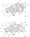
- Figure 1 shows a pallet 1 with an essentially rectangular basic structure 2 and four side surfaces enclosing the basic structure 2 3. Of the four side surfaces 3, two side surfaces 3 are arranged on opposite sides of the basic structure 2 and aligned parallel to one another. Apart from structural stiffening structures, the basic structure 2 has an essentially flat upper side 4 and an essentially flat lower side 5, the latter in the top view of FIG Figure 1 cannot be seen. In addition, the basic structure 2 is mirror-symmetrical to an imaginary center line 14 running in the longitudinal direction of the pallet 1, ie elements and sections of one side are mirror-symmetrical on the other side of the center line 14, even if they are not provided with reference numerals.
- funnel-shaped depressions 16 are provided, each forming a foot 6 for supporting the basic structure 2 from a floor surface.
- a central truncated pyramid 24 extends from the bottom of the depression 16 (see Figure 2 ) upwards, the surface of which is flush with the pallet top 4.
- Two of the four feet 6 have an elongated cross section, the longer axes of which are aligned parallel to the longitudinal axis of the pallet 1.
- one of the narrower walls is cut out, so that a passage 17 extending from the upper side 4 of the basic structure 2 to the lower side 5 of the basic structure 2 is formed.
- Each of the four side surfaces 3 has a centrally arranged recess 7 for receiving a display extension 8 (in Figure 1 not shown).
- a display extension 8 in Figure 1 not shown.
- vertically extending undercuts 9 are provided on the vertically extending boundaries of the recess 7, the undercuts 9 extending over the entire vertical extent of the recess 7.
- the horizontal cross-sectional area 10 of the recess 7 is rectangular and decreases from the bottom to the top 5, 4.
- the corners 12 of the pallet 1 are offset inwards and thus offer a further fastening possibility for projections arranged at the corners of the display, which can be put over the corners 12 of the pallet 1 offset inwards, for example.
- the receptacles 13 are rectangular slots which are arranged in the upper side 4 of the basic structure 2 and have four side walls which extend to the lower side 5. The height of these side walls corresponds to at least twice the minimum width of the slots.
- the basic structure of in Figure 1 also has two slot-shaped receptacles 13, arranged parallel to one another, for a fastening means along an imaginary line running parallel to one of the side surfaces 3.
- the basic structure 2 of the pallet 1 according to the invention has ten slot-shaped receptacles 13 on the upper side 4 - two receptacles 13 arranged on the center line and two receptacles 13 running parallel to the respective edges of the side surfaces 3 - which serve to hold fastening means.
- FIG 2 is a perspective view of the embodiment according to the Figure 1 shown.
- the basic structure 2 is alternately made up of ribs and depressions 18 which are stiffened by transverse struts, the basic structure 2 has an essentially flat top and bottom 4, 5. Both on the top 4 and on the bottom 5, fixing sections 19 are provided for fastening fixing bands.
- the fixing sections 19 are punched out of the respective top and bottom sides 4, 5. They have an elongated shape with rounded corners.
- the feet 6 are clearly recognizable on their outer side with a recess 15 for fastening packaging material and / or fastening means.
- the recesses 15 are triangular here and are arranged on the side surfaces of each foot 6, which run along the longitudinal direction of the pallet 1.
- the recesses 7 have vertically extending undercuts 9 at their vertically extending boundaries, the undercuts 9 extending over the entire vertical extent of the recess 7.
- the recesses 7 here in turn extend over the entire vertical extent of the respective side surface 3. In other words, each of the four side surfaces 3 is interrupted by one of the four recesses 7.
- the horizontal cross-sectional area 10 of the recess 7 is essentially rectangular, the horizontal cross-sectional area 10 decreasing from the underside 5 in the direction of the top 4. Due to the rectangular shape of the horizontal cross-sectional area 10 and its decrease in the direction of the top 4 of the basic structure, the recess 7 has a wedge-shaped profile tapering upwards in a section perpendicular to the side surface 3. A display extension 8 which is introduced into the recess 7 and has a corresponding wedge profile can, on the one hand, contact the rear boundary surface of the recess 7 and is supported thereby. On the other hand, folded-over wedge sections 22 engage behind the vertically extending webs 23, which form the undercuts 9, and thus prevent the display extension 8 from being able to be moved upward or laterally out of the recess 7.
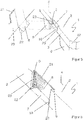
- FIG Figure 3 A perspective view of an embodiment according to the invention obliquely from below is shown in FIG Figure 3 shown.
- the top and bottom 4, 5 of the basic structure 2 are complementary to each other.
- Several pallets 1 can be stacked one above the other.
- FIG. 10 is a partially sectional perspective view of an embodiment according to FIG Figure 3 shown.
- the feet 6 are formed by a funnel-shaped depression 16 extending from the top 4, a central truncated pyramid 24 extending from the bottom of the depression 16 to the top 4.
- the end of the truncated pyramid 6 is flush with the top 4 of the basic structure 2.
- the basic structure has 2 depressions and ribs 18. These structures, alternately open at the top and bottom, are stiffened with cross struts and each define a level of the top and bottom 5, 4 of the pallet 1.
- Figure 5 shows a section of a pallet 1 according to the invention with recesses 7 for receiving a display extension 8.
- Two of the feet 6 supporting the basic structure 2 are shown, one foot 6 having an essentially elongated cross section compared to the other foot 6.
- a recess 15 is not provided in any of the side surfaces of the feet 6.
- a recess 7 for receiving a display extension 8 is provided on one side surface 3 shown. Recognizable, the recess 7 extends over the vertical extension of the side surface 3, so that the side surface 3 is interrupted by the recess 7.
- the recess 7 has vertically extending undercuts 9 at its vertically extending boundaries, which extend over the entire extend vertically of the recess 7 and are formed by webs 23 which extend flush with the side wall surface from the lateral boundaries of the recesses 7 and into the latter. Since the horizontal cross-sectional area 10 of the recess 7 (in Figure 5 indicated by a dashed line) decreases from the bottom 5 of the base structure 2 to the top 4 of the base structure, the side profile of the recess 7 and the undercuts 9 are wedge-shaped.
- a dovetail-shaped display extension 8 can be pressed into the recess 7 from the side, the lateral wedge sections 22 of the display extension 8 bending along a pre-folded line and partially bending open again after passing the webs 23 and engaging in the vertically extending undercuts 9.
- the fold edge lies against the rear wall boundary of the recess 7 and thus ensures that the wedge sections 22 are held in the undercuts 9 in a positive and non-positive manner.
- the wedge-like shape of the side undercut profile prevents the display extension 8 from being moved upwards out of the recess 7. Sliding down is prevented either by the display 20 resting on the top 4 of the pallet 1 or by engagement of projections in the recesses 11 of the webs 23.
- the display extension 8 is also supported on the rear wall boundary of the recess 7, which increases the stability. As shown here, the display 20 and the display extension 8 can have a corrugated cardboard structure 22.
- the basic structure 2 has inwardly offset corners 12.
- FIG. 6 A partial sectional view showing a perspective view of an embodiment according to Figure 5 with an engaged display extension 8 is in Figure 6 shown.
- the pallet 1 with an essentially rectangular basic structure 2 has four side surfaces 3 enclosing the basic structure 2 (only one of which is shown here).
- the side surface 3 has a recess 7, into which a display extension 8 is introduced.
- the display extension 8 has a corrugated cardboard structure 21 and two wedge sections 22 which can be bent along a pre-folded line.
- the bent wedge sections 22 engage in the vertically running undercuts 9 of the recess 7 and thus fix the display extension 8 in the recess 7. Because the horizontal cross-sectional area 10 of the recess 7 is rectangular and decreases from the underside 5 of the basic structure 2 in the direction of the top 4 , the side profile of the recess 7 is wedge-shaped.
- the wedge shape means that the wedge sections 22 of the display extension 8 cannot be moved out of the recess 7 in the direction of the upper side 4 of the basic structure 2.
- the display extension 8 can be supported on the rear wall recess 7 over a large area, so that the stability of the fastening is increased.
- Figure 7 is a perspective section according to Figure 6 shown on another embodiment of the present invention.
- the pallet 1 has all the features of the embodiment shown in the previous figures.
- the recess 7 extends over the vertical extent of the side surface 3 and has a horizontal cross section 10 which is rectangular and which decreases from the bottom to the top 5, 4.
- the recess 7 has undercuts 9 at its vertical boundaries which extend over the extent of the recess 7.
- the Undercuts 9 have a lateral wedge profile, into which, as shown here, a wedge section 22 of the display extension can engage.
- the webs 23 forming the undercuts 9 here have a horizontally running recess 11 into which a nose arranged on the wedge sections 22 can engage, whereby a vertical movement of the display extension 8 in the recess 7 can be prevented. Due to the slot-shaped recess 11, it is also possible to detach the wedge sections 22 from the undercut 9 if necessary. For this purpose, for example, a tool can be inserted into the slot-shaped recesses 11 with which the wedge sections 22 can be bent and pulled out of the undercuts 22. If the lugs introduced into the horizontally running recesses 11 protrude beyond the side surface 3, then no tools are required to bend the wedge sections 22 and to lead them out of the undercut 9.
Abstract
Die vorliegende Erfindung betrifft eine Palette (1) mit einer im Wesentlichen rechteckigen Grundstruktur (2) und vier die Grundstruktur (2) einfassenden Seitenflächen (3), von welchen je zwei Seitenflächen (3) auf gegenüberliegenden Seiten der Grundstruktur (2) angeordnet und parallel zueinander ausgerichtet sind, wobei die Grundstruktur (2) je eine von Versteifungsstrukturen abgesehen ebene Ober- und Unterseite (4, 5) aufweist und wobei an der Unterseite (5) Füße (6) zum Abstützen der Grundstruktur (2) angeordnet sind, wobei die Palette nach innen versetzte Ecken ausweist, dass Fortsätze an den Ecken eines Displaysockels über die nach innen versetzten Ecken stülpbar sind.The invention relates to a pallet (1) with an essentially rectangular basic structure (2) and four side surfaces (3) enclosing the basic structure (2), two side surfaces (3) of which are arranged on opposite sides of the basic structure (2) and parallel are aligned with each other, the base structure (2) each having a flat top and bottom (4, 5) apart from stiffening structures and wherein on the bottom (5) feet (6) for supporting the base structure (2) are arranged, the Pallet offset corners shows that extensions on the corners of a display base can be slipped over the offset corners.
Description
Die vorliegende Anmeldung betrifft eine Palette mit einer im Wesentlichen rechteckigen Grundstruktur und vier die Grundstruktur einfassenden Seitenflächen, von welchen je zwei Seitenflächen auf gegenüberliegenden Seiten der Grundstruktur angeordnet und parallel zueinander ausgerichtet sind, wobei die Grundstruktur je eine, von konstruktiven Versteifungsstrukturen abgesehen, ebene Ober- und Unterseite aufweist und wobei an der Unterseite Füße zum Abstützen der Grundstruktur angeordnet sind.The present application relates to a pallet with an essentially rectangular basic structure and four side surfaces enclosing the basic structure, of which two side surfaces are arranged on opposite sides of the basic structure and are aligned parallel to one another, the basic structure each having a flat top surface, apart from structural stiffening structures. and underside and feet are arranged on the underside for supporting the basic structure.
Derartige Paletten werden häufig zum Warentransport verwendet und sind oftmals in ein Pfandsystem integriert. Dies und ein möglichst breites Anwendungsfeld erfordern, dass die Abmessungen der Paletten vereinheitlicht sind. Abhängig von der Größe sind ¼-Europaletten, mit einer Grundfläche von 400 x 600 mm, halbe Europaletten, mit einer Grundfläche von 800 x 600 mm, und Europaletten, mit einer Grundfläche von 800 x 1200 mm, zu unterscheiden. Daneben sind eine Vielzahl von anderen Größen auf dem Markt verfügbar. Die vorliegende Erfindung ist primär für die Verwendung mit ¼-Europaletten vorgesehen, auch wenn eine Verwendung mit anderen Palettenmaßen nicht ausgeschlossen ist.Such pallets are often used to transport goods and are often integrated into a deposit system. This and the widest possible field of application require that the dimensions of the pallets are standardized. Depending on the size, ¼ euro pallets with a base area of 400 x 600 mm, half euro pallets with a base area of 800 x 600 mm, and euro pallets with a base area of 800 x 1200 mm can be distinguished. A variety of other sizes are also available on the market. The present invention is primarily intended for use with ¼ euro pallets, even if use with other pallet dimensions is not excluded.
Bekanntermaßen können Paletten aus diversen Materialien, wie z. B. Holz, Kunststoff oder Blech hergestellt sein. Die
Werden Paletten in Verkaufsräumen aufgestellt, um darauf befindliche Waren direkt, ohne diese erste in Regale einzusortieren, dem Kunden anzubieten, so werden die Paletten als sog. "Display-Paletten" bezeichnet. Display-Paletten dienen daher, neben dem Transport auch der Präsentation der Waren. Um eine verkaufsfördernde und ansprechende Wirkung auf die Kunden zu erzielen, werden die Paletten mit sog. Displays ummantelt.If pallets are set up in sales rooms so that the goods on them can be offered directly to the customer without sorting them on shelves, the pallets are referred to as "display pallets". Display pallets are therefore used not only for transport but also for the presentation of the goods. In order to achieve a sales-promoting and appealing effect on customers, the pallets are encased with so-called displays.
Displays sind oftmals zur Warenpräsentation entsprechend bedruckte Papp- oder Kartonaufbauten, die auf bzw. an der Palette befestigt werden. Neben der Funktion der Warenpräsentation können Displays während des Transportes auch zur Ladungssicherung verwendet werden. Für beide Verwendungszwecke ist es erforderlich, dass die Displays möglichst schnell, einfach und sicher an bzw. auf der Palette befestigt werden können. Entscheidend ist dabei vor allem, dass das Display die vorgegebene Position während des Transportes und in erster Linie während des Verkaufsvorganges beibehält.Displays are often appropriately printed cardboard or cardboard structures for product presentation, which are attached to or on the pallet. In addition to the function of product presentation, displays can also be used to secure loads during transport. For both purposes, it is necessary that the displays can be attached to or on the pallet as quickly, easily and securely as possible. The most important thing is that the display maintains the specified position during transport and primarily during the sales process.
Zu diesem Zweck weisen herkömmliche Paletten in den Randbereichen der Oberseite der Grundstruktur schlitzförmige Ausnehmungen auf, in die vorstehende Befestigungsstrukturen des Displays eingeführt werden können. Die vorstehenden Befestigungsstrukturen haben z.B. ausgeformte und/oder aufgesetzte Rastnasen, die in die schlitzförmigen Ausnehmungen eingreifen und verrasten. Nachteilig ist bei dieser Art der Befestigung vor allem der erhöhte Materialbedarf zur Herstellung der Rastnasen und das schwierige Einführen der Rastnasen in die schlitzförmigen Befestigungsstrukturen. Die Befestigung solcher Displays erfordert einen Zugang zu der Oberseite der Palette, der jedoch bei bereits beladenen Paletten nur begrenzt möglich ist. Zudem nimmt das eigentliche Display die Sicht auf die schlitzförmigen Ausnehmungen, so dass die Einführung der Befestigungsstrukturen in die Ausnehmungen "blind" zu erfolgen hat.For this purpose, conventional pallets have slot-shaped recesses in the edge regions of the upper side of the basic structure, into which protruding fastening structures of the display can be inserted. The above fastening structures have, for example, shaped and / or attached latching lugs which engage and latch into the slot-shaped recesses. A disadvantage of this type of fastening is above all the increased material requirement for producing the locking lugs and the difficult insertion of the locking lugs into the slot-shaped fastening structures. Fastening such displays requires access to the top of the pallet, but this is only possible to a limited extent with already loaded pallets. In addition, the actual display takes a view of the slit-shaped recesses, so that the fastening structures have to be introduced "blindly" into the recesses.
Eine alternative Befestigungsmöglichkeit sieht an den Seitenflächen der Paletten T-förmige Vertiefungen vor, die in etwa die Stärke des Displaymaterials haben. Bei der Verwendung von Displays aus Pappe sind die Vertiefungen daher wenige Millimeter, z. B. 2 bis 5 mm tief. Die an den Displays für das Hineinpressen in diese Vertiefungen vorgesehenen Abschnitte sind ebenfalls T-förmig und mit Übermaß ausgestaltet. Das Hineinpressen führt zu einer lokalen Materialverformung, die nur bei einer hinreichend dünnen Materialstärke möglich ist,. Diese Verformung verhindert jedoch, dass der Fortsatz des Displays zuverlässig in der Vertiefung der Palette eingepasst und damit sicher an der Palette befestigt werden kann. Wird die Materialstärke, um ungewollte Verformungen zu vermeiden, erhöht, ist ein Einbringen des Displayfortsatzes nur sehr mühsam oder gar nicht mehr möglich. In beiden Fällen ist eine sichere Verbindung zwischen Display und Palette nicht gewährleistet.An alternative fastening option provides T-shaped depressions on the side surfaces of the pallets, which have approximately the thickness of the display material. When using cardboard displays, the depressions are therefore a few millimeters, z. B. 2 to 5 mm deep. The sections provided on the displays for pressing into these depressions are also T-shaped and designed with oversize. Pressing it in leads to local material deformation, which is only possible with a sufficiently thin material thickness. However, this deformation prevents the extension of the display from being reliably fitted into the recess of the pallet and thus being securely attached to the pallet. If the material thickness is increased in order to avoid undesired deformations, it is very difficult or even impossible to insert the display extension. In both cases, a secure connection between the display and the pallet is not guaranteed.
Vor dem Hintergrund des genannten Standes der Technik ist es daher Aufgabe der vorliegenden Erfindung, eine Palette mit Aufnahmen zur sicheren und schnellen Befestigung eines Displays an einer Palette bereitzustellen.Against the background of the prior art mentioned, it is therefore an object of the present invention to provide a pallet with receptacles for securely and quickly attaching a display to a pallet.
Die vorliegende Aufgabe wird erfindungsgemäß gelöst durch eine Palette der eingangs erwähnten Art, wobei an zumindest zwei der vier Seitenflächen wenigstens eine Ausnehmung zur formschlüssigen Aufnahme eines Displayfortsatzes angeordnet ist. Die Palette ist vorzugsweise aus Kunststoff im Spritzgussverfahren oder durch Tiefziehen hergestellt.The present object is achieved according to the invention by a pallet of the type mentioned at the outset, at least one recess being arranged on at least two of the four side surfaces for the form-fitting reception of a display extension. The pallet is preferably made of plastic by injection molding or by deep drawing.
In einer besonders bevorzugten Ausführungsform erstreckt sich die Ausnehmung über die vertikale Ausdehnung der Seitenfläche. Dies ermöglicht einen zweiseitigen Zugang zu dem in die Ausnehmung eingebrachten Displayfortsatz. Das Ein- und Ausführen des Displayfortsatzes kann je nach Ausgestaltung von zwei Seiten her, d.h. einmal von der Oberseite her oder senkrecht zu der Seitenfläche und einmal von der Unterseite der Grundstruktur her, überwacht bzw. gesteuert werden. Der Displayfortsatz kann zu diesem Zweck auch mit einem Werkzeug ergriffen werden und in die Ausnehmung hinein bzw. aus der Ausnehmung heraus gezogen werden. Es ist nicht zwingend erforderlich, dass sich der Displayfortsatz selbst über die gesamte vertikale Ausdehnung der Ausnehmung erstreckt. Die untere Kante des Displays kann dabei auf dem Rand der Grundstruktur neben der Ausnehmung aufliegen, um so das Display abzustützen.In a particularly preferred embodiment, the recess extends over the vertical extent of the side surface. This enables two-sided access to the in the recess introduced display extension. Depending on the design, the insertion and execution of the display extension can be monitored or controlled from two sides, ie once from the top or perpendicular to the side surface and once from the bottom of the basic structure. For this purpose, the display extension can also be gripped with a tool and pulled into or out of the recess. It is not absolutely necessary that the display extension itself extends over the entire vertical extent of the recess. The lower edge of the display can rest on the edge of the basic structure next to the recess in order to support the display.
Weil die Ausnehmung sich über die vertikal verlaufende Ausdehnung der Seitenfläche erstreckt, ist darüber hinaus auch ein Zugang von der Seitenfläche auf die Ausnehmung möglich. Sowohl eine Kontrolle bzw. Überwachung des Ein- und Ausbringungsvorgangs des Displayfortsatzes von der Seite, als auch eine Sichtkontrolle der ordnungsgemäßen Befestigung ist jederzeit möglich. Im Bedarfsfall kann die Positionierung des Materialfortsatzes durch die seitliche, obere und/oder untere Zugriffsmöglichkeit korrigiert werden.Because the recess extends over the vertical extension of the side surface, access from the side surface to the recess is also possible. Both a control or monitoring of the insertion and removal process of the display extension from the side, as well as a visual inspection of the correct attachment is possible at any time. If necessary, the positioning of the material extension can be corrected using the side, top and / or bottom access option.
In einer weiteren Ausführungsform weist die Ausnehmung in der Draufsicht auf die Seitenflächen entlang ihrer vertikal verlaufenden Begrenzungen Hinterschneidungen auf, wobei die Hinterschneidungen sich vorzugsweise über die gesamte vertikale Ausdehnung der Ausnehmung erstrecken. Der in die Ausnehmung eingeführte Displayfortsatz wird vorzugsweise in der (bzw. den) vertikal verlaufenden Hinterschneidung(en) eingeklemmt. In Abhängigkeit von der Dimensionierung des in die Hinterschneidung eingebrachten Materialabschnittes entsteht so ein Formschluss, der eine sichere und feste Positionierung des Displayfortsatzes in der Ausnehmung gewährleistet.In a further embodiment, the recess has undercuts in the top view of the side surfaces along its vertically running boundaries, the undercuts preferably extending over the entire vertical extent of the recess. The display extension inserted into the recess is preferably clamped in the (or the) vertically running undercut (s). Depending on the dimensioning of the material section introduced into the undercut, a form fit is thus created which ensures a secure and firm positioning of the display extension in the recess.
Erstrecken sich die vertikalen Hinterschneidungen über die vertikale Ausdehnung der Ausnehmung, so können die Hinterschneidungen auch zur Justierung des Displayfortsatzes verwendet werden. Zu diesem Zweck kann der Displayfortsatz entlang der Hinterschneidung definiert bewegt werden, bis er die gewünschte Position erreicht hat. Zusätzlich bewirkt eine längere Hinterschneidung, dass die Kraft bzw. der Formschluss auf eine größere Kontaktfläche verteilt werden kann.If the vertical undercuts extend over the vertical extent of the recess, the undercuts can also be used to adjust the display extension. For this purpose, the display extension can be moved along the undercut in a defined manner until it has reached the desired position. In addition, a longer undercut means that the force or the positive fit can be distributed over a larger contact area.
In einer bevorzugten Ausführungsform weist die Ausnehmung eine horizontale Querschnittsfläche auf, die in eine Richtung von der Unterseite der Grundstruktur zu der Oberseite der Grundstruktur hin abnimmt. Anders ausgedrückt hat die Ausnehmung in einem Schnitt senkrecht zur Seitenfläche einen sich nach oben verjüngenden keilförmigen Querschnitt. Auch die Hinterschneidungen haben dann einen keilförmigen Querschnitt. Der in die keilförmigen Hinterschneidungen eingeführte Displayfortsatz kann gegen eine Bewegung in allen Richtungen verklemmt werden. Eine vertikale Bewegung des Displays ebenso wie horizontale Bewegungen können somit verhindert werden. Die Klemmkraft ist abhängig von der Materialstärke des in die Hinterschneidung eingebrachten Displayfortsatzes sowie dessen geometrischer Ausgestaltung.In a preferred embodiment, the recess has a horizontal cross-sectional area that decreases in a direction from the underside of the basic structure to the upper side of the basic structure. In other words, the recess has a wedge-shaped cross section tapering upwards in a section perpendicular to the side surface. The undercuts then also have a wedge-shaped cross section. The display extension inserted into the wedge-shaped undercuts can be jammed against movement in all directions. Vertical movement of the display as well as horizontal movements can thus be prevented. The clamping force is dependent on the material thickness of the display extension introduced into the undercut and its geometric design.
In einer weiter bevorzugten Ausführungsform ist die horizontale Querschnittsfläche der Ausnehmung im Wesentlichen rechteckig oder halbkreisförmig ausgeformt. Bei der Verwendung von schwalbenschwanzförmigen Displayfortsätzen und einer halbkreisförmig ausgestalteten Querschnittsfläche, bilden sich entlang des an der Rückwand, d. h. der inneren (zum Zentrum der Palette hin liegenden) Begrenzung der Ausnehmung, anliegenden Displayfortsatzes Kraftkomponenten aus, die in Richtung der Hinterschneidungen weisen und so die Haltekraft des in die Hinterschneidungen eingebrachten Displayfortsatzes erhöhen.In a further preferred embodiment, the horizontal cross-sectional area of the recess is essentially rectangular or semicircular. When using dovetail-shaped display extensions and a semicircular cross-sectional area, force components are formed along the display extension adjacent to the rear wall, i.e. the inner (towards the center of the pallet) border, which point in the direction of the undercuts and thus the holding force of the display extension inserted in the undercuts.
In einer Ausführungsform ist vorgesehen, dass im näher zu der Unterseite der Grundstruktur angebrachten Bereich der Ausnehmung eine weitere Aussparung in der Rückwand der Ausnehmung vorgesehen ist, die es ermöglicht, von der Unterseite der Grundstruktur aus zumindest abschnittsweise einen an die Rückwand der Ausnehmung angelegten Abschnitt des Displayfortsatzes mit einem Werkzeug und/oder einer Hand zu hintergreifen. Der Displayfortsatz kann so mit dem Werkzeug bzw. mit der Hand gegriffen werden und leicht aus der Ausnehmung entfernt werden. Die zum Hintergreifen vorgesehene Aussparung kann im Wesentlichen rechteckig oder halbkreisförmig ausgestaltet sein. Nicht ausgeschlossen sind andere geometrische Ausgestaltungen, solange diese ein zumindest abschnittsweises Hintergreifen mit einem Werkzeug bzw. einer Hand ermöglichen. Diese Aussparung liegt zweckmäßigerweise im Zentrum der Rückwand und somit entfernt von den Hinterscheidungen.In one embodiment it is provided that in the area of the recess which is located closer to the underside of the basic structure, a further recess is provided in the rear wall of the recess, which makes it possible, from the underside of the basic structure, at least in sections for a section of the recess applied to the rear wall of the recess To reach behind the display extension with a tool and / or one hand. The display extension can thus be gripped with the tool or by hand and easily removed from the recess. The recess provided for engaging behind can be essentially rectangular or semicircular. Other geometrical configurations are not excluded, as long as they allow an at least section-wise reaching behind with a tool or a hand. This recess is expediently located in the center of the rear wall and thus away from the undercuts.
In einer weiteren Ausführungsform werden die Hinterschneidungen gebildet durch je einen, sich von der Seiteanwand der Ausnehmung parallel zu den Seitenwänden der Palette und vorzugsweise bündig mit diesen erstreckende Stege gebildet.In a further embodiment, the undercuts are each formed by webs which extend from the side wall of the recess parallel to the side walls of the pallet and preferably extend flush with them.
Weiterhin weisen die vertikal verlaufenden die Hinterschneidungen bildenden Stege der Ausnehmung in einer bevorzugten Variante eine zusätzliche, horizontal verlaufende Aussparung auf, die bevorzugt schlitzförmig ausgestaltet ist. Die horizontale Aussparung in den vertikal verlaufenden Stegen ermöglicht eine horizontale Ausrichtung des Displayfortsatzes in der Ausnehmung. So können beispielsweise in die horizontale Aussparung Haltemittel eingebracht werden, die teilweise in das Material der Grundstruktur der Palette eindringen, nachdem sie einen in die Hinterschneidungen der Ausnehmung eingebrachten Abschnitt des Displayfortsatzes durchdrungen haben. Alternativ dienen die horizontalen Aussparungen der Aufnahme von horizontal auf dem Displayfortsatz auf- bzw. angebrachte Erhebungen. Derartige Erhebungen können beispielsweise Stege oder Nasen sein, die eingebracht in die horizontalen Aussparungen eine vertikale Bewegung des Displayfortsatzes in der Ausnehmung wirksam verhindern. Das Display muss dann nicht notwendigerweise auf der Oberseite der Palette aufsitzen. Die Aussparungen bieten auch eine Zugriffsmöglichkeit auf die in die Hinterschneidungen eingebrachten Abschnitte des Displayfortsatzes zum Lösen dieser Abschnitte.Furthermore, in a preferred variant, the vertically running webs of the recess forming the undercuts have an additional, horizontally running recess, which is preferably designed in the form of a slot. The horizontal recess in the vertical webs allows the display extension to be aligned horizontally in the recess. For example, holding means can be introduced into the horizontal recess, some of which penetrate into the material of the basic structure of the pallet after they have penetrated a section of the display extension introduced into the undercuts of the recess. Alternatively, the horizontal cutouts serve to accommodate the horizontal extension on the display extension. or appropriate surveys. Such elevations can be, for example, webs or noses, which, introduced into the horizontal cutouts, effectively prevent vertical movement of the display extension in the recess. The display does not necessarily have to sit on the top of the pallet. The cutouts also offer access to the sections of the display extension which are introduced into the undercuts in order to release these sections.
In einer Ausführungsform sind die Ausnehmungen zweier gegenüberliegender Seitenflächen bezüglich der Länge der Seitenflächen an entsprechenden Abschnitten angeordnet. Bevorzugt weist jede der vier Seitenflächen eine Ausnehmung auf, wobei die Ausnehmungen in den Seitenflächen mittig angeordnet sind.In one embodiment, the recesses of two opposite side faces are arranged on corresponding sections with respect to the length of the side faces. Each of the four side surfaces preferably has a recess, the recesses being arranged centrally in the side surfaces.
Erfindungsgemäß weist die Palette in einer Ausführungsform abgerundete und nach innen versetzte Ecken auf. Displaysockel mit Fortsätzen an den Ecken, die beispielsweise auch Rastnasen aufweisen können, können über die nach innen versetzten Ecken der Palette gestülpt werden, um so eine sichere und genaue Positionierung zu gewährleisten. Des Weiteren können Fixierbänder sicher und genau an der Palette positioniert werden, wobei die nach innen versetzten Ecken ein seitliches Verrutschen der Fixierbänder verhindern.According to the invention, the pallet in one embodiment has rounded corners that are offset inwards. Display bases with extensions at the corners, which can also have latching lugs, for example, can be slipped over the inwardly offset corners of the pallet in order to ensure safe and precise positioning. Furthermore, fixing straps can be positioned securely and precisely on the pallet, with the corners offset inwards to prevent the fixing straps from sliding sideways.
Die Grundstruktur weist in einer Ausführungsform entlang einer gedachten, parallel zu einer der Seitenflächen verlaufenden Linie wenigstens eine schlitzförmige Aufnahme für ein Befestigungsmittel auf. Eine schlitzförmige Aufnahme in diesem Sinne hat zumindest zwei Seitenwände, deren Höhe mindestens der minimalen Breite, vorzugsweise der doppelten minimalen Breite, des Schlitzes entspricht. Alternativ oder zusätzlich kann sich die Aufnahme durch einen Verrastungsmechanismus, wie beispielsweise Hinterschneidungen zur Aufnahme von Rastnasen, auszeichen. In derartige schlitzförmige Aufnahmen können Befestigungsmittel, wie z. B. Stege, eingebracht werden, die die Wände des Displays zusätzlich abstützen und ein Verrutschen verhindern. Bevorzugt sind entlang einer gedachten, parallel zu einer der Seitenflächen verlaufenden Linie zwei solcher schlitzförmigen Aufnahmen parallel zueinander angeordnet.In one embodiment, the basic structure has at least one slot-shaped receptacle for a fastening means along an imaginary line running parallel to one of the side surfaces. A slot-shaped receptacle in this sense has at least two side walls, the height of which corresponds to at least the minimum width, preferably twice the minimum width, of the slot. As an alternative or in addition, the receptacle can be secured by a latching mechanism, such as undercuts for receiving latching lugs, award. In such slot-shaped receptacles, fasteners such. B. webs can be introduced, which additionally support the walls of the display and prevent slipping. Two such slot-like receptacles are preferably arranged parallel to one another along an imaginary line running parallel to one of the side surfaces.
Im Allgemeinen haben die beiden Paare von gegenüberliegenden Seitenflächen unterschiedliche Längen, so dass die entlang der längeren Seitenflächen verlaufende Richtung zwanglos als Längsrichtung bezeichnet werden kann. Im Falle einer quadratischen Palette kann willkürlich eine der Richtungen der Seitenflächen als Längsrichtung definiert werden. In einer Ausführungsform sind entlang der in Längsrichtung verlaufenden Mittellinie zwei zueinander in Längsrichtung beabstandete Aufnahmen für Befestigungsmittel vorgesehen. Eine solche Aufnahme kann ein schlitzförmige Aufnahme in dem oben beschriebene Sinne sein. Mit Hilfe dieser Aufnahmen können auch Displays mit einer kleineren Grundfläche auf der Grundstruktur befestigt werden. Ist die Grundstruktur der Palette quadratisch ausgeführt, so tritt an die Stelle der Längsrichtung eine der zwei die Grundstruktur in einer Draufsicht halbierenden Mittellinien. Derartige, schlitzförmige Aufnahmen unterscheiden sich von anderen Durchbrüchen in der Ober- und Unterseite der Palette vor allem dadurch, dass sie sich senkrecht zur Ober- und Unterseite Wände erstreckende Seitenwände haben die in eine größere Tiefe reichen als die Wandstärke des Palettenmaterials oder etwaige Verstärkungsrippen.In general, the two pairs of opposite side faces have different lengths, so that the direction running along the longer side faces can be referred to as the longitudinal direction. In the case of a square pallet, one of the directions of the side surfaces can be arbitrarily defined as the longitudinal direction. In one embodiment, two receptacles for fastening means that are spaced apart from one another in the longitudinal direction are provided along the longitudinal center line. Such a recording can be a slit-shaped recording in the sense described above. With the help of these recordings, displays with a smaller footprint can also be attached to the base structure. If the basic structure of the pallet is square, one of the two center lines bisecting the basic structure in a plan view takes the place of the longitudinal direction. Such slot-like receptacles differ from other openings in the top and bottom of the pallet primarily in that they have side walls extending perpendicular to the top and bottom walls, which extend to a greater depth than the wall thickness of the pallet material or any reinforcing ribs.
Bevorzugt sind die auf der Mittellinie angeordneten Aufnahmen für ein Befestigungsmittel rechteckig ausgeformt.The receptacles arranged on the center line are preferably rectangular for a fastening means.
In einer Ausführungsform weist zumindest eine Seitenfläche eines Fußes der Palette, vorzugsweise zweier Füße und besonders bevorzugt aller Füße, eine Ausnehmung zum Befestigen von Verpackungsmaterial auf. Die Ausnehmungen an den Füßen können insbesondere dreieckig ausgeformt sein, wobei beispielsweise eine Stretchfolie in die Ausnehmung hineingeführt und in einer Ecke der dreieckigen Ausnehmung eingeklemmt werden kann. Vorgesehen ist auch, dass ein Fixierband mit beispielsweise einem Haken in der Aussparung der Seitenfläche zur Transportsicherung befestigbar ist.In one embodiment, at least one side surface of one foot of the pallet, preferably two feet, and particularly preferably all Feet, a recess for attaching packaging material. The recesses on the feet can in particular be triangular, for example a stretch film can be inserted into the recess and clamped in a corner of the triangular recess. It is also provided that a fixing tape can be fastened with a hook in the recess in the side surface for transport security, for example.
In einer besonders bevorzugten Ausführungsform werden die Füße durch eine von der Oberseite ausgehende trichterförmige Vertiefung gebildet von deren Grund sich ein zentraler Pyramidenstumpf sich bis zu der Oberseite erstreckt. Die Füße besten so gesehen näherungsweise aus einem in seiner vertikalen Mitte in sich zurück gefalteten Pyramidenstumpf. Vorzugsweise weisen zwei von vier Füßen einen länglichen Querschnitt auf, deren längere Achsen parallel zu der Längsachse der Palette ausgerichtet sind. Eine Wand der trichterförmigen Vertiefung der Füße kann durchbrochen sein, so dass man neben dem Fuss von der Oberseite zur Unterseite der Grundstruktur erstreckende Durchführung erhält.In a particularly preferred embodiment, the feet are formed by a funnel-shaped depression extending from the top, from the bottom of which a central truncated pyramid extends to the top. The feet are best seen from a truncated pyramid in its vertical center. Preferably two out of four feet have an elongated cross section, the longer axes of which are aligned parallel to the longitudinal axis of the pallet. A wall of the funnel-shaped depression of the feet can be perforated, so that a passage extending from the top to the bottom of the basic structure is obtained next to the foot.
In einer Ausführungsform weist die Grundstruktur im Wechsel nach oben offene und nach unten offene Vertiefungen/Rippen auf, die mit Querverstrebungen versteift sind. Eine derartig ausgestaltete Palette hilft, die Materialkosten bei der Herstellung zu senken, wobei in der Folge durch das verringerte Transportgewicht auch die Transportkosten sinken.In one embodiment, the basic structure alternately has upwardly open and downwardly open depressions / ribs which are stiffened with transverse struts. A pallet designed in this way helps to reduce the material costs during production, the transport costs also being reduced as a result of the reduced transport weight.
Zur Ladungssicherung in einer Ausführungsform beispielsweise vorgesehen, dass die Unterseite und/oder die Oberseite der Grundstruktur Fixierabschnitte für die Befestigung von Fixierbändern aufweist. Die Fixierbänder können aus der Ober- und Unterseite gestanzte Aussparungen sein, die beispielsweise eine längliche Form mit abgerundeten Ecken haben. Die herausgestanzten Aussparungen dienen auch dem Ablauf von Flüssigkeiten, welche sich sonst in den Vertiefungen der Palette sammeln könnten.For securing loads in one embodiment, it is provided, for example, that the underside and / or the top side of the basic structure has fixing sections for fastening fixing straps. The fixing straps can be recesses punched out of the top and bottom, which have, for example, an elongated shape with rounded corners. The punched-out recesses serve also the drainage of liquids that could otherwise collect in the recesses of the pallet.
In einer Ausführungsform ist die Palette derart ausgestaltet, dass mehrere Paletten übereinander stapelbar sind. Zu diesem Zweck ist bevorzugt die Unterseite der Grundstruktur derart komplementär zu der Oberseite der Grundstruktur ausgestaltet, dass zwei Paletten zumindest abschnittsweise ineinandergreifen.In one embodiment, the pallet is designed such that a plurality of pallets can be stacked one above the other. For this purpose, the underside of the basic structure is preferably designed to be complementary to the upper side of the basic structure such that two pallets interlock, at least in sections.
Weitere Vorteile, Merkmale und Anwendungsmöglichkeiten der vorliegenden Erfindung werden deutlich anhand der folgenden Beschreibung von bevorzugten Ausführungsformen und den dazugehörigen Figuren. Es zeigen:
-
Figur 1 -
Figur 2Figur 1 ; -
Figur 3 -
Figur 4Figur 3 -
Figur 5 -
Figur 6Figur 4 mit einem in Eingriff gebrachten Displayfortsatz; -
Figur 7Figur 5 einer weiteren Ausführungsform der Erfindung.
-
Figure 1 is a schematic plan view of an embodiment of the present invention; -
Figure 2 a perspective view of the embodiment of the inventionFigure 1 ; -
Figure 3 a perspective view of a pallet according to the invention obliquely from below; -
Figure 4 a perspective view, partially in section, inFigure 3 shown embodiment -
Figure 5 a section of a pallet according to the invention with a recess for receiving a display extension; -
Figure 6 a perspective view of an embodiment according toFigure 4 with an engaged display extension; -
Figure 7 a perspective section accordinglyFigure 5 a further embodiment of the invention.
Auf der Oberseite 4 sind vier trichterförmige Vertiefungen 16 vorgesehen die je einen Fuß 6 zum Abstützen der Grundstruktur 2 von einer Bodenfläche bilden. Vom Grund der Vertiefung 16 erstreckt sich ein zentraler Pyramidenstumpf 24 (siehe
Jede der vier Seitenflächen 3 weist eine mittig angeordnete Ausnehmung 7 zur Aufnahme eines Displayfortsatzes 8 (in
Die Ecken 12 der Palette 1 sind nach innen versetzt und bieten so eine weitere Befestigungsmöglichkeit für an den Ecken des Displays angeordnete Fortsätze, die beispielsweise über die nach innen versetzten Ecken 12 der Palette 1 gestülpt werden können.The
Auf der gedachten, in Längsrichtung verlaufenden Mittellinie 14 sind zwei voneinander in Längsrichtung beabstandete Aufnahmen 13 für Befestigungsmittel vorgesehen. In dieser Ausführungsform sind die Aufnahmen 13 rechteckige Schlitze, die in der Oberseite 4 der Grundstruktur 2 angeordnet sind und vier sich zu der Unterseite 5 erstreckende Seitenwände haben. Die Höhe dieser Seitenwände entspricht dabei mindestens der doppelten minimalen Breite der Schlitze.On the imaginary, longitudinally extending
Die Grundstruktur der in
In
Gut erkennbar weisen die Füße 6 an ihrer Außenseite eine Aussparung 15 zum Befestigen von Verpackungsmaterial und/oder Befestigungsmitteln auf. Die Aussparungen 15 sind hier dreieckig ausgestaltet und sind auf den Seitenflächen jeden Fußes 6 angeordnet, die entlang der Längsrichtung der Palette 1 verlaufen.The
Die Ausnehmungen 7 weisen an ihren vertikal verlaufenden Begrenzungen vertikal verlaufende Hinterschneidungen 9 auf, wobei die Hinterschneidungen 9 sich über die gesamte vertikale Ausdehnung der Ausnehmung 7 erstrecken. Die Ausnehmungen 7 erstrecken sich hier wiederum über die gesamte vertikale Ausdehnung der jeweiligen Seitenfläche 3. Mit anderen Worten ist jede der vier Seitenflächen 3 durch eine der vier Ausnehmungen 7 unterbrochen.The
Die horizontale Querschnittsfläche 10 der Ausnehmung 7 ist im Wesentlichen rechteckig ausgestaltet, wobei die horizontale Querschnittsfläche 10 von der Unterseite 5 in Richtung der Oberseite 4 abnimmt. Durch die rechteckige Form der horizontalen Querschnittsfläche 10 und deren Abnahme in Richtung der Oberseite 4 der Grundstruktur, weist die Ausnehmung 7 in einem Schnitt senkrecht zu der Seitenfläche 3 ein sich nach oben verjüngendes keilförmiges Profil auf. Ein Displayfortsatz 8 welcher in die Ausnehmung 7 eingebracht wird und ein entsprechendes Keilprofil aufweist, kann sich einerseits an die hintere Begrenzungsfläche der Ausnehmung 7 anlegen und wird dadurch abgestützt. Andererseits greifen umgefaltete Keilabschnitte 22 hinter die vertikal verlaufenden Stege 23, welche die Hinterschneidungen 9 bilden und verhindern so, dass der Displayfortsatz 8 nach oben oder seitlich aus der Ausnehmung 7 hinaus bewegt werden kann.The horizontal
Eine perspektivische Ansicht einer erfindungsgemäßen Ausführungsform von schräg unten ist in
In
Weiter ist erkennbar, dass die Grundstruktur 2 Vertiefungen und Rippen 18 aufweist. Diese im Wechsel nach oben und unten offene Strukturen sind mit Querverstrebungen versteift und definieren je eine Ebene der Ober- bzw. der Unterseite 5, 4 der Palette 1.It can also be seen that the basic structure has 2 depressions and
An der einen gezeigten Seitenfläche 3 ist eine Ausnehmung 7 zur Aufnahme eines Displayfortsatzes 8 vorgesehen. Erkennbar erstreckt sich die Ausnehmung 7 über die vertikal verlaufende Ausdehnung der Seitenfläche 3, so dass die Seitenfläche 3 durch die Ausnehmung 7 unterbrochen ist.A
Die Ausnehmung 7 weist an ihren vertikal verlaufenden Begrenzungen vertikal verlaufende Hinterschneidungen 9 auf, die sich über die gesamte vertikale Ausdehnung der Ausnehmung 7 erstrecken und von Stegen 23 gebildet werden, die sich bündig mit der Seitenwandoberflläche von den seitlichen Begrenzungen der Ausnehmungen 7 und in diese hinein erstrecken. Da die horizontale Querschnittsfläche 10 der Ausnehmung 7 (in
Ein schwalbenschwanzförmiger Displayfortsatz 8 kann von der Seite in die Ausnehmung 7 gedrückt werden, wobei sich die seitlichen Keilabschnitte 22 des Displayfortsatzes 8 entlang einer vorgefalzten Linie umbiegen und nach dem Passieren der Stege 23 wieder teilweise aufbiegen und in die vertikal verlaufenden Hinterschneidungen 9 eingreifen. Die Falzkante liegt dabei an der rückwandigen Begrenzung der Ausnehmung 7 an und gewährleistet so, dass die Keilabschnitte 22 form- und kraftschlüssig in den Hinterschneidungen 9 gehalten werden. Die keilartige Form des seitlichen Hinterschneidungsprofils verhindert dabei, dass der Displayfortsatz 8 nach oben aus der Ausnehmung 7 heraus bewegt werden kann. Ein Herausgleiten nach unten wird verhindert entweder durch das Aufsitzen des Displays 20 auf der Oberseite 4 der Palette 1 oder durch Eingriff von Vorsprüngen in die Aussparungen 11 der Stege 23.A dovetail-shaped
Der Displayfortsatz 8 wird zudem an der rückwandigen Begrenzung der Ausnehmung 7 großflächig abgestützt, wodurch die Stabilität erhöht ist. Wie hier dargestellt, kann das Display 20 und der Displayfortsatz 8 eine Wellpappenstruktur 22 aufweisen.The
Ebenfalls in
Eine teilweise einen Schnitt zeigende, perspektivische Ansicht auf eine Ausführungsform gemäß
Die Seitenfläche 3 weist eine Ausnehmung 7 auf, in die ein Displayfortsatz 8 eingebracht ist. Der Displayfortsatz 8 hat eine Wellpappenstruktur 21 und zwei Keilabschnitte 22, die entlang einer vorgefalzten Linie abknickbar sind.The
Die abgeknickten Keilabschnitte 22 greifen in die vertikal verlaufenden Hinterschneidungen 9 der Ausnehmung 7 und fixieren so den Displayfortsatz 8 in der Ausnehmung 7. Weil die horizontale Querschnittsfläche 10 der Ausnehmung 7 rechteckig ausgestaltet ist und von der Unterseite 5 der Grundstruktur 2 in Richtung der Oberseite 4 abnimmt, ist das Seitenprofil der Ausnehmung 7 keilförmig. Die Keilform bewirkt, dass die Keilabschnitte 22 des Displayfortsatzes 8 nicht in Richtung der Oberseite 4 der Grundstruktur 2 aus der Ausnehmung 7 heraus bewegt werden können. Zu dem kann der Displayfortsatz 8 an der rückwandigen Ausnehmung 7 großflächig abgestützt werden, so dass die Stabilität der Befestigung erhöht ist.The
In
Die die Hinterschneidungen 9 bildenden Stege 23 haben hier eine horizontal verlaufende Aussparung 11, in die eine an den Keilabschnitten 22 angeordnete Nase eingreifen kann, wodurch eine vertikale Bewegung des Displayfortsatzes 8 in der Ausnehmung 7 verhindert werden kann. Durch die schlitzförmige Aussparung 11 ist es weiter möglich, die Keilabschnitte 22 aus der Hinterschneidung 9 bei Bedarf zu lösen. Hierzu kann beispielsweise ein Werkzeug in die schlitzförmigen Aussparungen 11 eingeführt werden, mit dem die Keilabschnitte 22 umgebogen und aus den Hinterschneidungen 22 heraus gezogen werden können. Stehen die in die horizontal verlaufenden Aussparungen 11 eingebrachten Nasen über die Seitenfläche 3 hervor, so bedarf es keines Werkzeugs, um die Keilabschnitte 22 umzubiegen und aus der Hinterschneidung 9 herauszuführen.The
Für Zwecke der ursprünglichen Offenbarung wird darauf hingewiesen, dass sämtliche Merkmale, die sich aus der vorliegenden Beschreibung, den Zeichnungen und den abhängigen Ansprüchen für einen Fachmann erschließen, auch wenn sie konkret nur im Zusammenhang mit bestimmten weiteren Merkmalen beschrieben wurden, sowohl einzeln als auch in beliebigen Zusammenstellungen mit anderen der hier offenbarten Merkmale oder Merkmalsgruppen kombinierbar sind, soweit dies nicht ausdrücklich ausgeschlossen wurde oder technische Gegebenheiten derartige Kombinationen unmöglich oder sinnlos machen. Auf die umfassende, explizite Darstellung sämtlicher denkbarer Merkmalskombinationen und die Betonung der Unabhängigkeit der einzelnen Merkmale voneinander wird hier nur der Kürze und der Lesbarkeit der Beschreibung wegen verzichtet.For the purposes of the original disclosure, it is pointed out that all features which are apparent to a person skilled in the art from the present description, the drawings and the dependent claims, even if they have only been described concretely in connection with certain further features, both individually and in any combinations can be combined with other of the features or groups of features disclosed here, unless this has not been expressly excluded or technical circumstances make such combinations impossible or senseless. The comprehensive, explicit representation of all conceivable combinations of features and the emphasis on the independence of the individual features from one another are omitted here only for the sake of brevity and legibility of the description.
- 11
- Palettepalette
- 22nd
- GrundstrukturBasic structure
- 33rd
- SeitenflächeSide surface
- 44th
- OberseiteTop
- 55
- Unterseitebottom
- 66
- Fußfoot
- 77
- AusnehmungRecess
- 88th
- DisplayfortsatzDisplay extension
- 99
- vertikal verlaufende Hinterschneidungvertical undercut
- 1010th
- horizontale Querschnittsflächehorizontal cross-sectional area
- 1111
- horizontale Aussparunghorizontal recess
- 1212th
- Eckecorner
- 1313
- Aufnahmeadmission
- 1414
- MittellinieCenter line
- 1515
- AussparungRecess
- 1616
- Vertiefungdeepening
- 1717th
- Durchführungexecution
- 1818th
- Vertiefungen/RippenDepressions / ribs
- 1919th
- FixierabschnitteFixing sections
- 2020th
- DisplayDisplay
- 2121
- WellpappenstrukturCorrugated cardboard structure
- 2222
- KeilabschnitteWedge sections
- 2323
- Stegweb
- 2424th
- PyramidenstumpfTruncated pyramid
Claims (15)
Applications Claiming Priority (4)
| Application Number | Priority Date | Filing Date | Title |
|---|---|---|---|
| DE102011003999A DE102011003999A1 (en) | 2011-02-11 | 2011-02-11 | palette |
| EP18183163.7A EP3403942B1 (en) | 2011-02-11 | 2012-02-08 | Pallet |
| EP14004418.1A EP2878550A1 (en) | 2011-02-11 | 2012-02-08 | Pallet |
| EP12154453.0A EP2487117B1 (en) | 2011-02-11 | 2012-02-08 | Palette |
Related Parent Applications (3)
| Application Number | Title | Priority Date | Filing Date |
|---|---|---|---|
| EP12154453.0A Division EP2487117B1 (en) | 2011-02-11 | 2012-02-08 | Palette |
| EP18183163.7A Division EP3403942B1 (en) | 2011-02-11 | 2012-02-08 | Pallet |
| EP14004418.1A Division EP2878550A1 (en) | 2011-02-11 | 2012-02-08 | Pallet |
Publications (1)
| Publication Number | Publication Date |
|---|---|
| EP3636558A1 true EP3636558A1 (en) | 2020-04-15 |
Family
ID=45566910
Family Applications (6)
| Application Number | Title | Priority Date | Filing Date |
|---|---|---|---|
| EP12154453.0A Active EP2487117B1 (en) | 2011-02-11 | 2012-02-08 | Palette |
| EP18183163.7A Active EP3403942B1 (en) | 2011-02-11 | 2012-02-08 | Pallet |
| EP14004359.7A Active EP2878549B1 (en) | 2011-02-11 | 2012-02-08 | Pallet |
| EP14004418.1A Ceased EP2878550A1 (en) | 2011-02-11 | 2012-02-08 | Pallet |
| EP14004358.9A Active EP2878548B1 (en) | 2011-02-11 | 2012-02-08 | Pallet |
| EP19213762.8A Pending EP3636558A1 (en) | 2011-02-11 | 2012-02-08 | Pallet |
Family Applications Before (5)
| Application Number | Title | Priority Date | Filing Date |
|---|---|---|---|
| EP12154453.0A Active EP2487117B1 (en) | 2011-02-11 | 2012-02-08 | Palette |
| EP18183163.7A Active EP3403942B1 (en) | 2011-02-11 | 2012-02-08 | Pallet |
| EP14004359.7A Active EP2878549B1 (en) | 2011-02-11 | 2012-02-08 | Pallet |
| EP14004418.1A Ceased EP2878550A1 (en) | 2011-02-11 | 2012-02-08 | Pallet |
| EP14004358.9A Active EP2878548B1 (en) | 2011-02-11 | 2012-02-08 | Pallet |
Country Status (4)
| Country | Link |
|---|---|
| EP (6) | EP2487117B1 (en) |
| DE (1) | DE102011003999A1 (en) |
| ES (2) | ES2533183T3 (en) |
| PL (2) | PL3403942T3 (en) |
Families Citing this family (20)
| Publication number | Priority date | Publication date | Assignee | Title |
|---|---|---|---|---|
| EP3135596B1 (en) | 2015-08-31 | 2018-03-21 | Cabka GmbH & Co. KG | Plastic display pallet |
| DE202015104613U1 (en) * | 2015-08-31 | 2015-09-22 | Cabka Gmbh & Co. Kg | Plastic display pallet |
| DE102015012066A1 (en) | 2015-09-22 | 2017-03-23 | Karimov GmbH | Transport pallet, module and folded sheet therefor, and method of manufacturing a transport pallet |
| SG11201805956PA (en) | 2016-01-28 | 2018-08-30 | Chep Technology Pty Ltd | Dolly |
| US10494141B2 (en) | 2017-08-16 | 2019-12-03 | Chep Technology Pty Limited | Reconfigurable pallet/dolly platform |
| FI20175880A1 (en) * | 2017-10-09 | 2019-04-10 | Wimao Oy | Structural element, method for producing the same and use |
| CA188144S (en) | 2018-12-20 | 2020-09-03 | Chep Technology Pty Ltd | Pallet attachment |
| US11174070B2 (en) * | 2019-08-07 | 2021-11-16 | Rehrig Pacific Company | Stackable pallet |
| DE202021103161U1 (en) | 2021-06-10 | 2022-09-14 | Ipp Gmbh | charge carrier |
| DE202021103163U1 (en) | 2021-06-10 | 2022-09-20 | Ipp Gmbh | charge carrier |
| DE102021115057A1 (en) | 2021-06-10 | 2022-12-15 | Ipp Gmbh | charge carrier |
| DE102021115056A1 (en) | 2021-06-10 | 2022-12-15 | Ipp Gmbh | charge carrier |
| DE102021115058A1 (en) | 2021-06-10 | 2022-12-15 | Ipp Gmbh | charge carrier |
| DE202021103160U1 (en) | 2021-06-10 | 2022-09-15 | Ipp Gmbh | charge carrier |
| DE202021106621U1 (en) | 2021-12-03 | 2023-03-24 | Ipp Gmbh | charge carrier |
| DE102021131954A1 (en) | 2021-12-03 | 2023-06-07 | Ipp Gmbh | charge carrier |
| DE102021131955A1 (en) | 2021-12-03 | 2023-06-07 | Ipp Gmbh | charge carrier |
| DE202021106622U1 (en) | 2021-12-03 | 2023-03-27 | Ipp Gmbh | charge carrier |
| DE102022107556A1 (en) | 2022-03-30 | 2023-10-05 | Schoeller Allibert Gmbh | SYSTEM WITH AT LEAST ONE LIGHTWEIGHT PALLET AND AT LEAST ONE CONTAINER LAYER WITH ONE OR MORE CONTAINERS |
| EP4311791A1 (en) * | 2022-07-29 | 2024-01-31 | Motherson Innovations Company Ltd. | Pallet |
Citations (8)
| Publication number | Priority date | Publication date | Assignee | Title |
|---|---|---|---|---|
| FR1397498A (en) * | 1964-03-20 | 1965-04-30 | J A Benoit S A Soc | Pallet loading device |
| FR2128054A1 (en) * | 1971-03-02 | 1972-10-20 | Papeteries De Lumbres | Expanded polystyrene pallet - which supports the sidewalls of a cardboard pack |
| DE3806069A1 (en) * | 1987-02-26 | 1988-09-15 | Schoeller & Co Ag A | Pallet |
| DE9304350U1 (en) * | 1993-03-23 | 1993-05-27 | Siemens Nixdorf Informationssysteme Ag, 4790 Paderborn, De | |
| EP1473247A2 (en) * | 2003-04-28 | 2004-11-03 | The Boeing Company | Enhanced aerial delivery system (eads) platform |
| DE202005004645U1 (en) * | 2005-03-16 | 2005-05-25 | Smurfit Europa Carton Gmbh | Combined cardboard box-pallet unit has at least a lug in the box bottom section that is formed as a stamped extension of the bottom flap that extends through a locating slit in the pallet |
| WO2010057586A1 (en) | 2008-11-19 | 2010-05-27 | Aks Kunststoff Systeme Gmbh & Co. Kg | Plastic pallet |
| GB2486661A (en) * | 2010-12-21 | 2012-06-27 | Smurfit Kappa Corrugated Uk Ltd | Container locking mechanism |
Family Cites Families (6)
| Publication number | Priority date | Publication date | Assignee | Title |
|---|---|---|---|---|
| ATE115494T1 (en) * | 1991-07-23 | 1994-12-15 | Siemens Nixdorf Inf Syst | REUSABLE CONTAINERS FOR PACKAGING GOODS OF ALL KINDS. |
| US20050145144A1 (en) * | 2004-01-05 | 2005-07-07 | Gab Christopher N. | Pallet |
| EP1705130A1 (en) * | 2005-03-21 | 2006-09-27 | AVK Plastics B.V. | Pallet and method of securing goods onto a pallet |
| DE202009018185U1 (en) * | 2009-10-22 | 2011-05-12 | Lidl Stiftung & Co. Kg | Plastic pallet for the transport of goods |
| WO2011003126A1 (en) * | 2010-04-19 | 2011-01-13 | Vinex Australia Pty Ltd | Pallets made of plastics or paper |
| DE202010016859U1 (en) * | 2010-12-22 | 2011-03-24 | Arpack Gmbh | Pallet for receiving goods carriers |
-
2011
- 2011-02-11 DE DE102011003999A patent/DE102011003999A1/en active Pending
-
2012
- 2012-02-08 EP EP12154453.0A patent/EP2487117B1/en active Active
- 2012-02-08 EP EP18183163.7A patent/EP3403942B1/en active Active
- 2012-02-08 ES ES12154453.0T patent/ES2533183T3/en active Active
- 2012-02-08 EP EP14004359.7A patent/EP2878549B1/en active Active
- 2012-02-08 ES ES18183163T patent/ES2773716T3/en active Active
- 2012-02-08 EP EP14004418.1A patent/EP2878550A1/en not_active Ceased
- 2012-02-08 PL PL18183163T patent/PL3403942T3/en unknown
- 2012-02-08 EP EP14004358.9A patent/EP2878548B1/en active Active
- 2012-02-08 PL PL12154453T patent/PL2487117T3/en unknown
- 2012-02-08 EP EP19213762.8A patent/EP3636558A1/en active Pending
Patent Citations (8)
| Publication number | Priority date | Publication date | Assignee | Title |
|---|---|---|---|---|
| FR1397498A (en) * | 1964-03-20 | 1965-04-30 | J A Benoit S A Soc | Pallet loading device |
| FR2128054A1 (en) * | 1971-03-02 | 1972-10-20 | Papeteries De Lumbres | Expanded polystyrene pallet - which supports the sidewalls of a cardboard pack |
| DE3806069A1 (en) * | 1987-02-26 | 1988-09-15 | Schoeller & Co Ag A | Pallet |
| DE9304350U1 (en) * | 1993-03-23 | 1993-05-27 | Siemens Nixdorf Informationssysteme Ag, 4790 Paderborn, De | |
| EP1473247A2 (en) * | 2003-04-28 | 2004-11-03 | The Boeing Company | Enhanced aerial delivery system (eads) platform |
| DE202005004645U1 (en) * | 2005-03-16 | 2005-05-25 | Smurfit Europa Carton Gmbh | Combined cardboard box-pallet unit has at least a lug in the box bottom section that is formed as a stamped extension of the bottom flap that extends through a locating slit in the pallet |
| WO2010057586A1 (en) | 2008-11-19 | 2010-05-27 | Aks Kunststoff Systeme Gmbh & Co. Kg | Plastic pallet |
| GB2486661A (en) * | 2010-12-21 | 2012-06-27 | Smurfit Kappa Corrugated Uk Ltd | Container locking mechanism |
Also Published As
| Publication number | Publication date |
|---|---|
| PL2487117T3 (en) | 2015-05-29 |
| EP2487117A1 (en) | 2012-08-15 |
| EP2878550A1 (en) | 2015-06-03 |
| ES2773716T3 (en) | 2020-07-14 |
| EP2878549B1 (en) | 2016-07-20 |
| EP3403942A1 (en) | 2018-11-21 |
| EP2487117B1 (en) | 2014-12-31 |
| DE102011003999A1 (en) | 2012-08-16 |
| EP2878549A1 (en) | 2015-06-03 |
| EP3403942B1 (en) | 2019-12-11 |
| EP2878548A1 (en) | 2015-06-03 |
| EP2878548B1 (en) | 2016-09-14 |
| ES2533183T3 (en) | 2015-04-08 |
| PL3403942T3 (en) | 2020-08-24 |
Similar Documents
| Publication | Publication Date | Title |
|---|---|---|
| EP2487117B1 (en) | Palette | |
| EP3124391B1 (en) | Support assembly | |
| EP3094568B1 (en) | Container for transporting goods and device for dividing such a container | |
| EP1754897B1 (en) | Storage device | |
| EP3569110B1 (en) | Flower box | |
| DE602005000018T2 (en) | Storage system and components for it | |
| EP3303731B1 (en) | Framework platform element, in particular for scaffolding | |
| DE2255086C2 (en) | Spacer connecting member for the production of a multi-layer wall | |
| DE4101486C2 (en) | Device for releasably connecting preferably flat parts | |
| EP2324732B1 (en) | Storage rack, in particular automatic small part storage | |
| WO2011023188A2 (en) | Permanent formwork and formwork system | |
| EP3753857B1 (en) | Wall element of a pallet stacking frame and pallet stacking frame | |
| DE102012000242B4 (en) | Stackable pallet of goods | |
| EP2767483B1 (en) | Stackable transport container | |
| EP1279356B1 (en) | Shelf base for a shelf and shelving unit | |
| DE202014102178U1 (en) | Shelf Traverse | |
| EP2927157B1 (en) | Transport securing device for winding reels | |
| EP3659479B1 (en) | Tub support made of a hard foam and parts of a tub support stacked in a shipping arrangement | |
| EP2526838B1 (en) | Shelf made of foldable sheet material | |
| EP2227610B1 (en) | Carrying structure | |
| EP3974347A1 (en) | Shelf panel with deformation | |
| WO2004113741A1 (en) | Assembly system for furniture | |
| DE212020000379U1 (en) | palette | |
| EP1066774B1 (en) | Shelving unit | |
| DE102017008168A1 (en) | Display element for goods-carrying displays and method for producing a goods-carrying display |
Legal Events
| Date | Code | Title | Description |
|---|---|---|---|
| PUAI | Public reference made under article 153(3) epc to a published international application that has entered the european phase |
Free format text: ORIGINAL CODE: 0009012 |
|
| STAA | Information on the status of an ep patent application or granted ep patent |
Free format text: STATUS: THE APPLICATION HAS BEEN PUBLISHED |
|
| AC | Divisional application: reference to earlier application |
Ref document number: 3403942 Country of ref document: EP Kind code of ref document: P Ref document number: 2487117 Country of ref document: EP Kind code of ref document: P Ref document number: 2878550 Country of ref document: EP Kind code of ref document: P |
|
| AK | Designated contracting states |
Kind code of ref document: A1 Designated state(s): AL AT BE BG CH CY CZ DE DK EE ES FI FR GB GR HR HU IE IS IT LI LT LU LV MC MK MT NL NO PL PT RO RS SE SI SK SM TR |
|
| STAA | Information on the status of an ep patent application or granted ep patent |
Free format text: STATUS: REQUEST FOR EXAMINATION WAS MADE |
|
| 17P | Request for examination filed |
Effective date: 20200924 |
|
| RBV | Designated contracting states (corrected) |
Designated state(s): AL AT BE BG CH CY CZ DE DK EE ES FI FR GB GR HR HU IE IS IT LI LT LU LV MC MK MT NL NO PL PT RO RS SE SI SK SM TR |
|
| STAA | Information on the status of an ep patent application or granted ep patent |
Free format text: STATUS: EXAMINATION IS IN PROGRESS |
|
| 17Q | First examination report despatched |
Effective date: 20220707 |