EP3600675B1 - Zerkleinerungsvorrichtung - Google Patents
Zerkleinerungsvorrichtung Download PDFInfo
- Publication number
- EP3600675B1 EP3600675B1 EP18734437.9A EP18734437A EP3600675B1 EP 3600675 B1 EP3600675 B1 EP 3600675B1 EP 18734437 A EP18734437 A EP 18734437A EP 3600675 B1 EP3600675 B1 EP 3600675B1
- Authority
- EP
- European Patent Office
- Prior art keywords
- comb
- comminution
- flap
- machine frame
- spring means
- Prior art date
- Legal status (The legal status is an assumption and is not a legal conclusion. Google has not performed a legal analysis and makes no representation as to the accuracy of the status listed.)
- Active
Links
Images


Classifications
-
- B—PERFORMING OPERATIONS; TRANSPORTING
- B02—CRUSHING, PULVERISING, OR DISINTEGRATING; PREPARATORY TREATMENT OF GRAIN FOR MILLING
- B02C—CRUSHING, PULVERISING, OR DISINTEGRATING IN GENERAL; MILLING GRAIN
- B02C18/00—Disintegrating by knives or other cutting or tearing members which chop material into fragments
- B02C18/06—Disintegrating by knives or other cutting or tearing members which chop material into fragments with rotating knives
- B02C18/14—Disintegrating by knives or other cutting or tearing members which chop material into fragments with rotating knives within horizontal containers
- B02C18/145—Disintegrating by knives or other cutting or tearing members which chop material into fragments with rotating knives within horizontal containers with knives spaced axially and circumferentially on the periphery of a cylindrical rotor unit
-
- B—PERFORMING OPERATIONS; TRANSPORTING
- B02—CRUSHING, PULVERISING, OR DISINTEGRATING; PREPARATORY TREATMENT OF GRAIN FOR MILLING
- B02C—CRUSHING, PULVERISING, OR DISINTEGRATING IN GENERAL; MILLING GRAIN
- B02C18/00—Disintegrating by knives or other cutting or tearing members which chop material into fragments
- B02C18/06—Disintegrating by knives or other cutting or tearing members which chop material into fragments with rotating knives
- B02C18/16—Details
- B02C18/18—Knives; Mountings thereof
- B02C2018/188—Stationary counter-knives; Mountings thereof
Definitions
- the invention relates to a comminution device for comminuting comminution material, with a machine frame, a driven comminution roller mounted on the machine frame and having comminution tools, a comb having counter-tools and a comb flap pivotably mounted on the machine frame, the comminution roller interacting with the comminution, whereby the comminution is pivotally mounted on the comb flap in the region of its upper end, at least one spring means engaging with its first end on the comb and the comb being resiliently supported by the spring means.
- Devices of this type which are usually used for the comminution of feed material, in particular substrates, preferably in the waste and recycling area, are already known in the prior art and usually have at least one rotatably driven comminution roller.
- Individual tools or comminution tools in particular teeth, cutting edges and / or movable flails, are provided on the cylindrical jacket of the comminution roller, that is to say on the roller body.
- these comminution tools interact with the counter-tools of the comb, the counter-tools of the comb being designed in such a way that when the comminution roller rotates or rotates, the feed material is comminuted.
- the comb is usually designed as a comb bar for holding the tools and usually extends at least substantially over the entire width of the comminution roller.
- the comb can be made in one or more parts.
- the comb as a whole can be dismantled with the counter tools and can be exchanged for an already pre-equipped comb with "new" counter tools, so that an exchange of worn and / or overloaded, mostly damaged counter tools is made possible in a time-saving manner.
- the comb also called a comb bar
- the comb can be used both in terms of its distance to the shredding roller, in particular radially to the shredding roller, and also with respect to its inclination about its longitudinal axis, so that the best possible adaptation to the process task can be achieved.
- the comb is designed such that it can deflect in the event of an overload and there is an opening area between the comminution roller and the comb, so that damage to the machine is at least substantially avoided.
- an overload can be caused by the fact that the diameter of a feed piece corresponds approximately to or is greater than the clear distance between the comminution roller and the comb, so that the feed piece in question cannot be easily shredded.
- the comb is designed as a rocker which is designed to be pivotable about an axis. Therefore, the comb is also called the "comb beam”.
- the large comb flap can be opened for revision purposes or to replace the comb, so that easy, almost ground-level access to the inner machine area can be ensured, with which access the cleaning or maintenance and repair work can be carried out.
- the comb flap can be pivoted either in the upper area or in the lower area of the machine frame. When the comb flap is swung open, the comb is also moved at the same time, so that the entire unit can be opened when the comb flap is swung open.
- the prior art provides for the comb to be pivotably supported on the comb flap.
- a spring means acts on the comb, which engages the comb with its first end and is mounted on the comb flap with its second end.
- the arrangement of the second end of the spring means on the comb flap means that the entire reaction forces from the comminution process are absorbed by the comb flap and transferred to the machine frame via the latter.
- This configuration requires that the comb flap is made appropriately reinforced in order to achieve high rigidity.
- the disadvantage here is that the very rigid design of the comb flap and / or the comb results in high system costs and an increased weight of the entire comminution device means that the comminution device is transported, for example, when changing location, significantly more difficult.
- the smallest possible weight of the comminution device is desirable, since the total weight of mobile machines is limited due to approval regulations.
- the DE 299 10 772 U1 shows a comminution machine with fixed, comb-like teeth and a rotor with circumferentially attached, laterally offset rotor teeth relative to the fixed teeth, which are movable between the fixed, comb-like teeth when the rotor rotates.
- Another such shredding device is from DE29809078U known.
- the object of the invention is now to provide a comminution device which avoids or at least substantially reduces the aforementioned disadvantages in the prior art.
- the object of the present invention is to provide a comminution device which is lighter in weight than the comminution devices known in the prior art.
- the invention is defined by the appended claims.
- the above-mentioned object is at least essentially achieved according to the invention in a comminution device of the type mentioned at the outset in that the spring means is supported with its second end directly on the machine frame.
- the comb flap By supporting the spring means with the second end directly on the machine frame, a significant reduction in the bending moment that occurs on the comb flap is achieved compared to the prior art, since the reaction forces absorbed by the comb are dissipated directly into the machine frame without being passed over the comb flap. As a result, the comb flap at least essentially has to absorb almost no or only slight loads, which are then introduced directly into the machine frame.
- there is at least essentially no more flow of force in the comb flap so that preferably the comb flap only has to be designed for its necessary inherent stability and can accordingly be carried out simply and with reduced weight.
- the comb flap at least essentially only takes on the weight of the comb, in particular the comb beam rocker, and preferably does not take over any more forces from the work process as such.
- the comb flap is relieved of the majority of the reaction forces and can therefore be designed to save weight.
- the solution according to the invention appears to be disadvantageous since the spring means is arranged with its longitudinal axis at an angle to the crest which deviates from the 90 ° angle. It is important in this context that the 90 ° angle between the longitudinal axis of the spring means and the comb ensures the best possible transfer of force from the comb to the spring means.
- the advantages of an arrangement of the spring means according to the invention clearly outweigh the disadvantages with regard to the deviation of the 90 ° angle.
- the reaction forces that act on the comb are not transmitted at an optimal 90 ° angle
- arranging the spring means with its second end on the machine frame enables a significant reduction, namely by up to 90%, of the bending moment acting on the comb flap. Due to the reduced bending moment, the comb flap can be made significantly less stiff, but at the same time the plant and / or occupational safety can be easily guaranteed.
- the spring means also acts as a damping means, so that the comb can dodge in the event of an overload and there is a widened distance between the shredding roller and the comb. Accordingly, damage to the machine that would otherwise be caused particularly due to an overload can be avoided.
- the center of the joint of the comb flap and the articulation point of the spring means are arranged at its second end at least substantially on the same kinematic axis or lie on it.
- the comb flap rotates around the kinematic axis when it is swiveled. In the regular operating state, the comb flap is firmly connected to the machine frame. It is therefore advantageous when opening or swinging open the comb flap, in particular together with the comb, does not cause a change in position of the comb with respect to the comb flap. By avoiding a relative movement of the comb to the comb flap, the control engineering complexity of a hydraulic movement during the pivoting process of the comb flap is reduced.
- the 90 ° position is related to the tangential effect, which refers to the circular swiveling path of the comb when it dodges in the event of an overload.
- Bearing lugs with bearing openings are preferably provided or fastened on the machine frame, which serve to connect or couple with the comb flap and the spring means. It is particularly preferred if the center points of the bearing openings lie on the kinematic axis.
- the arrangement of the center points of the bearing openings on the kinematic axis has the advantage that the comb flap can be opened without changing the position of the comb relative to the comb flap.
- the mounting brackets enable in particular one simple arrangement of the comb flap or the spring means on the machine frame.
- the comb flap is arranged on the bearing brackets with their swivel bearing at the bottom of the machine frame. The upper area of the comb flap indicates that it faces the material to be comminuted, which is fed onto the size reduction device, and the lower area is in particular facing a surface on which the size reduction device is positioned.
- the shredding device has at least one locking device for locking the comb flap in the closed state of the comb flap, the locking device being effective between the comb flap and the machine frame.
- the locking device locks the comb flap on the machine frame.
- the comb flap supports the comb bar or the comb to the machine frame for short path lengths.
- the comb flap is preferably stiffened in this area, but in particular this stiffening can be neglected in comparison to the total weight or in comparison to the proportion of the total weight, the costs resulting from the stiffening of the comb flap in the area of the locking device being almost negligible or not weight.
- the locking device preferably does not take on high forces from the work process, since the majority of the forces and moments that occur are dissipated directly to the machine frame by means of the spring means.
- the comb flap can be swung open together with the comb, so that there is an opening area or an access possibility to the inner area of the shredding device.
- the locking device has, in particular wedge-like, locking bolts, the locking bolts being arranged on the comb flap and the machine frame having locking openings for engagement of the locking bolts.
- the locking bolts are brought into engagement with the locking openings of the machine frame by introducing them into the locking openings.
- the locking bolts are fixed in their end position, in particular in the locked state of the comb flap, so that opening of the locking device or pivoting open of the comb flap is only possible after loosening the fixing of the locking bolts.
- the locking bolts are provided on the side of the comb flap opposite the pivot bearing of the comb flap.
- the comb is designed as a comb beam rocker mounted at least in the region of its two ends.
- the design of the comb as a comb beam rocker enables, in particular, that the comb can deflect in the event of an overload and allows a gap between the comminution roller and the comb, which preferably ensures the removal of comminution material, which in particular has a critical diameter.
- the comb is pivotally mounted on the comb flap.
- the comb can also be constructed in several parts, the counter tools of the comb being designed to interact with the comminution tools of the comminution roller.
- the comb preferably extends at least substantially over the entire width of the comb flap and is pivotably mounted in each case in the side edge region of the comb flap.
- the comb likewise extends at least essentially over the width of the comminution roller, the counter tools of the comb interacting with the comminution tools of the comminution roller in such a way that the comminution material is comminuted.
- the comb is mounted on the one hand by the spring means on the machine frame and on the other hand pivotably on the comb flap. Since the comb advantageously extends over the width of the comb flap, the pivot bearing is provided on the front area of the comb flap, and consequently in the side edge region of the comb flap.
- the swivel mounting of the comb does not have to be provided directly on the front side of the comb flap, but only in an area that is in the vicinity of the front end of the comb flap.
- it is preferably not only pivotably mounted in the side edge regions of the comb flap, but also, for example, in the central region of the comb flap.
- the swivel mounting of the comb only has to absorb low reaction forces and transfer it to the comb flap, as a Most of the forces and moments that occur during the work process are derived from the spring means on the machine frame.
- the comb is preferably mounted in the upper region of the comb flap, the pivot bearing points of the comb being arranged adjacent to the locking bolts of the locking device.
- the distance between the pivot bearing points of the comb or the pivot bearing of the comb to the locking bolts is preferably 1 cm to 100 cm, preferably from 5 cm to 50 cm, more preferably from 5 cm to 30 cm.
- the comb flap is preferably stiffer in the area between the pivot bearing of the comb and the locking bolts than in the remaining area of the comb flap, so that reliable operation of the comminution device is ensured.
- the comb is arranged in the upper region of the comb flap and is stored in the side edge regions, that is to say in the upper side edge regions of the comb flap.
- the comb is formed in one piece and is supported on the comb flap by two pivot bearing points.
- the comb is advantageously designed in such a way that it can perform a pivoting movement.
- the spring means is designed in such a way that it allows the comb to pivot, in particular to increase the distance, preferably the clear distance, between the comminution roller and the comb, in particular in the event of an overload.
- the distance between the shredding roller and the comb is more than 2 cm and can be increased to 20 cm, in particular in the event of an overload and during an evasive movement, in particular up to 40 cm.
- the comb After an evasive action or after a swiveling movement of the comb, the comb returns to its starting position due to the spring force of the spring means.
- An evasive movement of up to 40 cm enables non-crushable material to be ejected.
- the spring means is designed as a hydraulic cylinder and / or pressure holding cylinder.
- the movement of the spring means is preferably carried out in a force-controlled manner, the comb, in particular the comb beam rocker, being able to perform a pivoting movement in the event of an overload.
- a hydraulic tumbler for the force-controlled swiveling movement of the comb can be carried out by means of hydraulic cylinders with a defined pre-pressure accumulator.
- the spring means are preferably designed in such a way that they adjust the inclination of the comb about its longitudinal axis and can increase or decrease the distance to the comminution roller.
- the spring means take over a large part of the forces that result from the support of the comb.
- the cylinders absorb the forces and transmit them to the machine frame.
- the aforementioned cylinders also serve in particular to position the comb against the comminution roller, depending on the desired comminution result.
- the spring means is designed as a hydraulic cylinder and is coupled to a hydraulic control device.
- the hydraulic control device is designed such that it can control and / or regulate, in particular change and / or adjust, the spring force of the hydraulic cylinder, in particular in connection with the pressure accumulators of the hydraulic cylinders.
- the spring means does a job to move or pivot the comb, which is why the aforementioned cylinders can also be assigned to the working cylinders.
- the cylinders can at least essentially have the shape of a circular cylinder and / or be designed as a hollow cylinder.
- a spring means engages with its first end on the rear in the lateral region of the comb.
- the first end of the spring means indicates that the spring means engages with one end region on the comb.
- the second end engages in a bearing bracket on the machine frame.
- at least two spring means act on the comb, at least one spring means acting on each lateral edge region of the comb.
- the comb is preferably formed in one piece and extends, at least essentially, across the width of the comb flap.
- the lateral spring means in particular take over the largest part of the reaction forces from the work process and direct the reaction forces in the machine frame. The reaction forces are absorbed axially through the longitudinal axis of the spring means supporting the comb bar.
- a further spring means acts on the back of the central region of the comb with its first end.
- at least two spring means on the rear of the lateral area and at least one further spring means on the rear of the central area of the comb have their respective first ends.
- the use of the further cylinder also ensures that the central area of the comb is supported, the bending load on the comb can thus be greatly reduced, since the additional spring means also derives the reaction forces from the central area of the comb directly into the machine frame.
- the comminution device has a device for measuring and / or controlling and / or regulating the swivel angle of the comb.
- a displacement measuring means is advantageously provided, the device having this displacement measuring means and / or the device being coupled to the displacement measuring means .
- the spring means is also coupled to the device, wherein the spring means can adjust the swivel angle of the comb.
- the displacement measuring means is coupled in particular via the device to the spring means and / or the spring means, the measured distance of the comb from the machine frame being able to be used to control and / or regulate the swivel angle of the comb.
- the spring means are advantageously used to adjust the swivel angle of the comb, so that the displacement measuring means can have an indirect influence on the spring means and in particular on the swivel angle of the comb.
- the path measuring device can also record special operating states, in particular whereby an immediate shutdown of the comminution device can be triggered if the swivel angle of the comb deviates too much from the desired value.
- comminution material is carried out which is not comminutable and has a diameter which exceeds the maximum swiveling movement of the comb, this can be recorded in particular by the displacement measuring means. Since this too large, non-comminutable feed material would cause the comb to pivot, which would extend beyond the range of the permitted swiveling movement of the comb or would limit the maximum limit value of the swiveling angle of the comb, it makes sense to switch off the comminution device, in particular with regard to safety-related aspects. After an immediate shutdown, this critical feed material can be manually removed from the comminution device by the operating personnel.
- the displacement measuring means in particular in the form of a cylinder, is preferably arranged at one end on the rear of the comb and at the other end on the machine frame, preferably on the kinematic axis. One end engages the back of the comb and the other end engages the machine frame.
- Bearing brackets each with a bearing opening on the machine frame, are also provided for the displacement measuring device.
- the bearing plates for the displacement measuring means are arranged on the kinematic axis, in particular with the center of the bearing opening for the displacement measuring means also lying on the kinematic axis, so that preferably all center points of the bearing plates for the spring means and for the displacement measuring means lie on the same axis, so that there is no change in position of the other end of the displacement measuring means to the comb flap when pivoting open or during a, in particular circular, pivoting process of the comb flap.
- the displacement measuring device is designed as a sensor, in particular the device being coupled to a storage device which records and stores the movement of the comb or the pivoting angle of the comb. Accordingly, operational processes, especially for later evaluation, can be traced.
- the end position of the comb can be set at least essentially freely, preferably controlled and / or regulated, using the displacement measuring means.
- the displacement measuring device indicates the position of the comb, in particular the comb beam rocker.
- an opening device is effective between the machine frame and the comb flap, the opening device being designed to automatically pivot the flap. After the comb flap has been swung open, the opening device enables access to the inner area of the comminution device in order to maintain the tools of the comminution roller as required exchange. In addition, the opened opening flap also allows access to the comb in order to maintain and / or replace the comb's counter tools.
- the opening device advantageously pivots the comb flap about the kinematic axis, the center points of the joint or the pivot bearing of the comb flap being arranged on the kinematic axis.
- the opening device is preferably designed such that a force-controlled lowering of the comb flap is ensured.
- the opening device can only initiate pivoting of the comb flap when the locking device is unlocked and permits pivoting of the comb flap.
- the opening device preferably has at least one hydraulic cylinder which is attached with one end to the machine frame, in particular to a lateral bearing wall, and with its other end to a longitudinal edge side of the comb flap.
- the hydraulic cylinder enables the comb flap to be swiveled open or swiveled in a force-controlled manner.
- a hydraulic cylinder is provided on the respective longitudinal edge sides of the comb flap. The hydraulic cylinders are supported on the machine frame when the comb flap is pivoted.
- a material feed hopper in particular directly on the machine frame, is preferably provided for feeding the material to be comminuted above the comminution roller and the counter-comb.
- the material feed hopper can also be arranged above the comminution device, in particular not connected to the machine frame.
- the machine frame has a first bearing wall and a second bearing wall opposite the first bearing wall, at least one comminution roller being provided between the first bearing wall and the second bearing wall, wherein in the region of a first opening in the first bearing wall
- the gearbox connection of a gearbox projects with which the comminution roller is connected in terms of gear on its first end face facing the gearbox connection, and an opening for the comminution roller is provided in the second bearing wall.
- an opening area open to the outside is provided which merges into the second opening.
- the invention relates to a comminution device or a device for comminution with a comb arranged on the comb flap, the comb being supported directly on the machine frame by means of at least one spring means.
- the load on the comb flap is significantly reduced, so that the entire size reduction device can be designed to save weight.
- Fig. 1 shows a comminution device 1 for use for comminuting comminution material with a first bearing wall 2 and a second bearing wall 3, a comminution roller 5 or its roller body 14, which has comminution tools 22, being provided between the first bearing wall 2 and the second bearing wall 3.
- the first bearing wall 2 has a first opening 6 for arranging the comminution roller 5.
- the second bearing wall 3, on the other hand, has a second opening 10 for arranging the comminution roller 5.
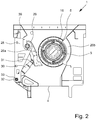
- the first bearing wall 2 and the second bearing wall 3 as well as the roller body 15 are enclosed in a machine frame 4, as can be seen in particular Fig. 2 results.
- Fig. 1 not all components required for the function of the comminution device 1 are shown. So it shows Fig. 1 neither the flange connection 16 nor the mounting plate 17.
- Comminution devices 1 of the type in question can in principle be used in all areas in which a feed material is to be comminuted.
- devices 1 of the type in question are used for comminuting waste and recycling material.
- Fig. 3 shows components of a device 1, intended for use for comminution, with a machine frame 4 having a first bearing wall 2 and a second bearing wall 3 opposite the first bearing wall 2, with at least one comminution roller 5 provided between the first bearing wall 2 and the second bearing wall 3, whereby through a first Opening 6 in the first bearing wall 2 protrudes a gear connection 7 of a gear 8, to which the comminution roller 5 is connected in a geared manner on its first end face 9 facing the gear connection 7, and a second opening 10 for the comminution roller 5 is provided in the second bearing wall 3.
- a comminution device 1 of the type in question not only to have a comminution roller 5, but also a plurality, in particular two, of comminution rollers 5.
- an opening area 12 is provided which opens outwards and merges into the second opening 10. This results in particular from Fig. 5 .
- the second opening 10 of the second bearing wall 3 is thus accessible to the outside up to at least one edge side 11 of the second bearing wall 3 via an opening area 12.
- the shredding roller 5 can be removed from the shredding device 1 via the opening area 12 or inserted into the shredding device 1 via the opening area 12 and coupled to the gear connection 7.
- the comminution roller 5 comprises the roller body 14 and the comminution tools 22.
- the shredding roller 5 is connected to the second bearing wall 3 via a fastening plate 17.
- the fastening plate 17 is arranged in the region of the second end face 15 on the comminution roller 5. How from the Fig. 3 and 4th results, the fastening plate 17 covers the opening area 12 and the second opening 10.
- the comminution roller 5 is arranged on the fastening plate 17 via a flange connection 16 or is mounted or fastened on the fastening plate 17 via screw connections.
- the flange connection 16 which has a substantially annular shape, is fastened on the end face to the roller body 14 and serves to connect the comminution roller 5 to the fastening plate 17.
- the flange connection 16 can be used for the direct connection of the comminution roller 5 to the second bearing wall 3, in which case a fastening plate 17 can be dispensed with entirely.
- a fastening means 18 covering or bridging the opening region 12 is provided, which is designed to connect the regions of the second bearing wall 3 adjoining the opening region 12.
- the fastener 18 is in accordance with Fig. 8 firmly, in particular via screw connections, connected to the second bearing wall 3.
- fastening means 18 can also be used without a fastening plate 17.
- the fastening means 18 is arranged in the area of the edge 11 of the second bearing wall 3, so that the opened opening area 12 only results after the fastening means 18 has been released.
- a hinged and / or pivotable bracket is provided as the fastening means 18.
- the bracket can be designed to be openable by using a hinge and / or a band.
- Fig. 8 shows that the fastening means 18 is provided in the form of a, in particular rectangular, plate which is connected on its two end faces to the second bearing wall 3, in particular in a non-positive manner.
- the gear connection 7 has the shape of an externally toothed plurality of shaft journals.
- the comminution roller 5 has an internally toothed element or an internal toothing, so that the gear connection between the gear connection 7 and the comminution roller 5 can be established.
- the first end face 9 of the comminution roller 5 is used for coupling to the gear connection 7, which in turn is arranged within the first opening 6 on the first bearing wall 2.
- the internal toothing of the comminution roller 5 in the area of the first end face 9 has depressions and / or projections corresponding to the projections and / or depressions of the shaft journal.
- Fig. 6 shows that the shaft journal of the gear connection 7 protrudes from the first bearing wall 2 and is arranged in the inner region of the comminution roller 5.
- a pin can also protrude from the comminution roller 5 in the region of the first end face 9 and is connected to the transmission connection 7, the transmission connection 7 of the transmission 8 then having an opening and no longer necessarily from the first Bearing wall 2 protrudes.
- the opening area 12 in combination with the second opening 10 forms on the second bearing wall 3 an at least substantially U-shaped overall opening which is open to the outside.
- Fig. 5 shows that this U-shaped total opening is open upwards or towards the upper edge side or edge 11 of the second bearing wall 3.
- the comminution roller 5 is consequently removed from the device 1 via the upper edge 11 of the second bearing wall 3.
- the comminution roller can also be removed laterally or downward from the comminution device 1, the opening region 12 then starting from the second opening 10, if necessary, to the marginal edges 11 of the sides or the lower marginal edge 11 of the second Bearing wall 3 extends.
- Fig. 4 and 5 that between the mounting plate 17 and the second bearing wall 3 effective centering means 19 for centering the shredding roller 5 are provided.
- these centering means 19 are at least substantially cylindrical in the form of a pin.
- the centering means 19, in particular the centering pins, correspond to centering openings 20 which are designed to receive the centering pins.
- the centering pin is in accordance with Fig. 5 provided on the second bearing wall 3, in particular on the regions of the second bearing wall 3 adjacent to the opening area 12 and to the second opening 10.
- the centering pin can also be attached to the fastening plate 17 and / or to the flange connection 16 of the comminution roller 5 may be provided.
- centering pins have a length that is greater than the length of the gear connection between the shredding roller 5 and the gear 8, so that during assembly there is first a centering over the centering pins and only then the gear connection between the shredding roller 5 and the transmission 8 is produced.
- the fastening plate 17 has screw connections 23 for arrangement on the second bearing wall 3.
- twelve screw connections 23 are provided. After loosening the screw connections 23, the fastening plate 17 can be separated from the second bearing wall 3, so that the fastening plate 17 is detachably connected to the second bearing wall 3 and thus to the machine frame 4.
- the flange connection 16 of the comminution roller 5 has at least two screw connections 24.
- the flange connection 16 has eight screw connections 24 for arrangement on the fastening plate 17.
- the screw connections 24 of the flange connection 16 can be provided for direct arrangement on the second bearing wall 3.
- the flange connection 16 has eight threaded bores in the present case, which are then designed to accommodate jack screws. Not only the flange connection 16 can have the aforementioned threaded bores, but also the fastening plate 17. In the end, it goes without saying that the forcing screws can also be used through threaded bores on the second bearing wall 3.
- the jacking screws are designed so that they allow a spatial separation between the mounting plate 17 and / or the flange connection 16 of the shredding roller 5 and the second bearing wall 3 when screwing in.
- the forcing screws are not arranged in the threaded holes or they are secured, in particular with lock nuts.
- actuators in particular adapted hydraulic actuators, are used, so that a horizontal or axial movement of the comminution roller 5 for separating the transmission connection 7 from the interior of the comminution roller 5 is ensured.
- the fastening plate 17 has a flattened area 21 on its lower edge 11.
- This flattened area 21 is designed in such a way that it can be arranged on a flat surface, preventing the attachment plate 17 and the comminution roller 5 attached to it from tipping over.
- the Fig. 1 shows that the shredding roller 5 is supported on both sides, being connected at its first end 9 to the transmission connection 7 of the transmission 8 and in the area of its second end 15 via the flange connection 16 with the fastening plate 17 and thus with the second Bearing wall 3 is connected.
- the gear 8 is firmly connected to the first bearing wall 2, although it is in principle also possible to arrange the gear 8 separately on a base, while the gear connection 7 then only projects through the first opening 6 of the first end face 9.
- Fig. 1 otherwise shows a shredding roller 5, which has a plurality of shredding tools 22.
- the comminution tools 22 can be designed as knives and / or teeth.
- the Fig. 1 that the shredding device 1 has a roller flap 26b arranged on the machine frame 4.
- the roller flap 26b has ribs 26c which have free spaces for the comminution tools 22 to pass through. It is not shown that the roller flap 26b is designed to be pivotable.
- the comminution device 1 has a comb 26a arranged on the machine frame 4, the comb 26a corresponding to the comminution tools 22 of the comminution roller 5 having counter tools 27.
- the interaction of the comb 26a with the comminution roller 5 results in comminution of the feed material in operation if the comminution roller 5 is driven via the gear 8 by means of a motor coupled to it.
- the comb 26a is arranged on a pivotable comb flap 28.
- the comb flap 28 is mounted on the machine frame 4.
- Fig. 11 and 12th the individual process steps for assembling and / or disassembling a comminution roller 5 of a comminution device 1 of the aforementioned type are shown.
- the shows Fig. 11 the process of disassembly.
- step A the lifting belts are first put on the shredding roller 5. It is not shown that at least two lifting belts are required for lifting out.
- step A is provided. that after and / or before the lifting belts hit the shredding roller 5, the roller flap 26b is pivoted open.
- the comb flap 28 has been pivoted in order to increase the distance between the comb 26a and the comminution roller 5. It is not shown that in a further embodiment it is provided that the comb 26a before the connection 3 is loosened, if possible is brought close to the comb flap 28.
- step B the screws or screw connections 23 are loosened.
- the forcing screws are then screwed into the threaded openings of the fastening plate 17 and / or the flange connection 16 in step C.
- step D the gear connection between the gear connection 7 of the gear 8 and the comminution roller 5 is released in a horizontal or axial movement.
- the individual jack screws are only screwed in one piece at a time, so that the gearing connection is loosened as evenly as possible without tilting.
- the comminution roller 5 is fixed by the centering means 19.
- the comminution roller 5 After releasing the gear connection, accompanied by a predetermined movement in the axial direction, the comminution roller 5 is moved in step E in a radial movement out of the second opening 10 of the second bearing wall 3 through the opening area 12 which is open to the outside. Depending on the arrangement and course of the opening area 12, this movement can take place upwards and / or sideways and / or downwards. Preferably, the lifting belts are not moved during the loosening of the gear connection and the axial movement in step E.
- the comminution roller 5 is deposited. In step H, the deposit is advantageously made on the flattened area 21 of the fastening plate 17, the flattened area 21 being arranged on a substrate.
- the shredding roller in particular with its end opposite the fastening plate 17, does not rest on the substrate, it is arranged at this end on a bearing block 25 or placed thereon.
- the bearing block 25 has at least substantially the same hub height as the shredding roller 5 and adapts to the bearing height of the fastening plate 17.
- the bearing block 25 can also be designed such that it enables a geared connection to the comminution roller 5.
- the bearing block can then have a corresponding shaft journal.
- Such a bearing block 25 makes it possible to rotate the shredded roller 5 for repair purposes.
- the bearing block 25 is connected to a rotating device which, in a further embodiment, has a power-operated drive.
- the rotating device is designed such that it can rotate the comminution roller 5, in particular wherein the shaft journal is connected to the comminution roller 5 in a suitable manner.
- a replacement of the shredding tools 22 of the shredding roller 5 can take place in the disassembled state from the shredding device 1 on the shredding roller 5 by rotating the shredding roller 5 in step G, which is preferably supported on the fastening plate 17 and on the bearing block 25. After the shredding roller 5 has been rotated, the, in particular damaged, shredding tools 22 can be replaced.
- Fig. 11 For the assembly of the comminution roller 5 in the comminution device 1, an analogous method is provided in comparison to the disassembly, the in Fig. 11 process steps shown are run backwards.
- the Fig. 12 shows the process sequence for assembling a shredding roller 5.
- step ⁇ the lifting belts are arranged on the shredding roller 5 and this is released from the bearing block 25.
- the shredding roller 5 is moved into the shredding device 1 through the opening area 12 from above and / or from below and / or laterally into the second opening 10. At any rate towards the end, this is a radial movement.
- roller flap 26b has ribs 26c, it must be swiveled towards the gear connection 7 after arranging the first end face 9 of the shredding roller 5.
- the comb flap 28 has been pivoted towards the gear connection 7 after the first end face 9 of the comminution roller 5 has been arranged. It is not shown that in a further embodiment it is provided that the comb 26a is brought as close as possible to the comminution roller 5 after the comminution roller 5 has been arranged.
- step ⁇ the comminution roller 5 is moved in the axial direction, the centering means 19 engaging in the respective centering openings 20.
- step ⁇ the gear teeth are produced between the gear connection 7 of a gear 8 and the comminution roller 5, in particular on the drive side in the region of its first end face 9.
- the arrangement on the gear connection 7 of the comminution roller 5 takes place in a horizontal or axial movement, the comminution roller 5 already being centered in the region of the second bearing wall 3 via the centering means 19.
- the gear connection is established in step ⁇ after the comminution roller 5 has already been arranged on the gear connection 7 by the horizontal movement in step ⁇ .
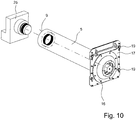
- the Fig. 10 shows the comminution roller 5 in the disassembled state from the comminution device 1, the first end face 9 of the comminution roller 5 being arranged on a bearing block 25.
- the mounting plate 17 is arranged over a flattened area 21 on a surface.
- the shredding tools 22 of the shredding roller 5 do not rest on the ground.
- FIG. 1 a comminution device 1 for comminuting comminuted material, with a machine frame 4, a driven comminution roller 5 mounted on the machine frame 4 and having comminution tools 22, a comb 26a having counter tools 27 and a comb flap 28 pivotably mounted on the machine frame 4, the comminution roller with comminution roller the comb 26a cooperates, the comb 26a being pivotally mounted on the comb flap 28 in the region of its upper end 29, at least one spring means 30 engaging the comb 26a with its first end 31 and the comb 26a being resiliently supported by the spring means 30.
- the spring means is arranged with its first, front end 9 on the comb 26a.
- the first end 31 of the spring means 30 can also be provided only in the end region of the spring means 30 and not necessarily on the end face of the spring means 30 Fig. 1 that the spring means 30 is supported with its second end 32 on the machine frame 4.
- the second end 32 of the spring means 30 need not be provided on the front end region 31 of the spring means 30.
- the comb 26a is pivotally mounted via the spring means 30 and is supported directly on the machine frame 4.
- the axis about which the comb 26a can pivot is provided in the region of its upper end 29, since the comb 26a is pivotably mounted on the comb flap 28 in the region of its upper end 29.
- the material feed hopper 48 is arranged on the machine frame 4.
- the Machine feed hopper 48 arranged above the shredding device 1 and not connected to the machine frame 4.
- the Fig. 15 shows parts or components of the machine frame 4 as well as the comb flap 28, the comb 26a and the spring means 30 Fig. 15 it can be seen that the articulation center points 12 of the comb flap 28, about which the comb flap 28 is designed to pivot, and the articulation point 34 of the spring means 30 lie on the same kinematic axis 35 at its second end 32.
- the comb flap 28 as by Fig. 16 and 18th is clarified, there is no change in position of the second end 32 of the spring means 30, since the second end 32 is arranged on the kinematic axis 35.
- the second end 32 is arranged on the machine frame 4, but is not on the kinematic axis 35.
- Fig. 17 that 4 mounting brackets 36 are provided on the machine frame.
- the bearing tabs 36 have bearing openings 37.
- the comb flap 28 and the spring means 30 are connected to the bearing tabs 36 in the region of the bearing openings 37.
- Corresponding bearing bolts are provided for this purpose, which engage in the bearing openings 37.
- the center points of the bearing openings 37 lie on the kinematic axis 35.
- both the comb flap 28 and the spring means 30 are designed in their end region in such a way that both the spring means 30 and the comb flap 28 are firmly connected to the machine frame 4 via the bearing plates 36.
- the reaction forces from the work process that is to say from the comminution of the feed material, are introduced into the machine frame 4 by the comb 26a via the spring means 30 and the bearing plates 36.
- the comb 26a extends at least substantially over the width of the comb flap 28.
- the spring means 30 engage with their first ends 31 on the rear side 45 of the comb 26a.
- the comb 26a can also be formed in several parts.
- the Fig. 19 shows the swivel-mounted comb 26a and the comb flap 28, the rear wall 45 for the arrangement of the spring means 30 being missing in the illustration.
- the swiveling or swiveling of the comb flap 28 takes place about the kinematic axis 35 in the lower region of the comb flap 28, as can be seen from this Fig. 18 results.
- At least one locking device 38 is provided for locking the comb flap 28 in the closed state and thus for firmly connecting the comb flap 28 to the machine frame 4.
- the Fig. 18 shows that the locking device 38 between the comb flap 28 and the machine frame 4 is effective.
- the locking device 38 firmly connects the comb flap 28 to the machine frame 4, the comb flap 28 only opening or swiveling open after the locking device 38 has been unlocked, as is the case with Fig. 16 and 18th can be seen is possible.
- the locking device 38 has locking bolts 39.
- the locking bolts 39 are arranged on the side of the comb flap 28 which lies opposite the pivot bearing 41 of the comb flap 28.
- the comb flap 28 is pivoted about the pivot bearing 41 of the comb flap 28 or about the kinematic axis 35.
- the opposite side of the comb flap 28 performs an at least essentially circular pivoting movement during the pivoting process.
- the locking bolts 39 are like this Fig. 18 clarified, wedge-shaped or cylindrical and arranged on the comb flap 28.
- the locking bolts 39 engage in locking openings 40 in the machine frame 4.
- the locking bolts 39 are moved out of the locking openings 40 of the machine frame 4, so that the comb flap 28 is no longer locked on the machine frame 4.
- the locking bolt 39 In the closed state of the comb flap 28, the locking bolt 39 is fixed or held in its end position by an additional fixing means 49. To unlock the locking device 38, the locking bolt 39 must therefore not only be moved out of the locking opening 40 of the machine frame 4, but also the fixing means 49 is released from the locking bolt 39.
- the Fig. 13 shows that the comminution device 1 has at least two locking devices 38, which are arranged at least essentially in the side edge region of the comb flap 28.
- the comb 26a can also be pivoted when the comb flap 28 is closed, the distance to the comminution roller 5 being changed by changing the position of the comb 26a or changing the pivoting angle of the comb 26a.
- Fig. 13 illustrates that the comb 26a is designed as a comb beam rocker mounted at least in the region of its two ends. The comb beam rocker is supported on the rear 45 of the comb 26a by the spring means 30 on the machine frame 4.
- the comb 26a extends at least essentially over the entire width of the comb flap 28 and is pivotably mounted in the side edge region of the comb flap 28. How from the Fig.
- the comb 26a is supported in its end regions, in particular in the vicinity of its end faces, on the comb flap 28 and is pivotably mounted on the upper region 42 of the comb flap 28.
- the comb flap 28 must also absorb part of the reaction forces and part of the load of the weight of the comb 26a.
- the forces which occur are introduced into the machine frame 4 via the locking device 38.
- the comb flap 28 takes over the support of the comb 26a to the machine frame 4 for short path lengths.
- the comb 26a is mounted in the upper region 42 of the comb flap 28 and the pivot bearing points of the comb 26a are arranged adjacent to the locking bolts 39.
- the locking bolts 39 are arranged from 1 cm to 40 cm adjacent to the pivot bearing points of the comb 26a.
- the spring means 30 is designed in such a way that it enables a pivoting movement of more than 2 cm.
- the comb 26a can perform an evasive movement of up to 40 cm. It is not shown that in further embodiments the distance between the shredding roller 5 and the comb 26a is between 2 cm to 20 cm. The pivoting movement increases the distance between the comminution roller 5 and the comb 26a Fig. 2 .
- This swiveling movement of the comb 26a usually takes place in the event of an overload, with comminution material that is too large or not easily comminuted gets into the gap between the comminution roller 5 and the comb 26a and an evasive movement of the comb 26a nevertheless enables this feed material to be conveyed away.
- the spring means 30 is how this turns out Fig. 5 results, designed as a hydraulic cylinder. In further embodiments, the spring means 30 can also hold the pressure cylinder be executed. The spring means 30 is designed such that it allows the comb beam rocker to swing in a force-controlled manner or enables the comb 26a to move in the event of an overload. In further embodiments, the spring means 30 also has a pre-pressure accumulator. The spring means 30 take over the support of the comb 26a and introduce the reaction forces, which result from the comminution of the comminution material and the interaction between the comminution tools 22 of the comminution roller 5 and the counter tools 27 of the comb 26a, into the machine frame 4.
- a spring means 30 on the rear edge 45 of the comb 26a engages with its first end 31 on the lateral edge region of the comb 26a. Furthermore shows Fig. 15 that the spring means 30, which engages the lateral edge area of the comb 26a, does not have to be arranged directly on the edge edge of the comb 26a, but is located in the edge area of the comb 26a. Between the two lateral spring means 30, a further spring means 30 is otherwise arranged in the central region of the comb 26a on its rear side 45, the further spring means 30 engaging with its first end 31 on the rear side 45 of the comb 26a.
- more than one spring means 30 can be arranged in the respective lateral edge regions of the comb 26a and / or also additional further spring means 30 in the central region of the comb 26a. Both the outer spring means 30 and the further, central spring means 30 absorb the reaction forces of the comminution process and the weight of the comb 26a and introduce these forces into the machine frame 4.
- a device 43 is provided for setting and / or controlling and / or regulating the pivoting angle of the comb 26a.
- a device 43 is provided for measuring and / or controlling the comb movement.
- the device 43 is coupled to the spring means 30, the device 43 being designed such that it can not only set the pivoting angle of the comb 26a via the spring means 30, but can also regulate it according to the measured pivoting angle.
- the Fig. 15 shows that the device 43 has a displacement measuring means 44.
- the displacement measuring device 44 is designed as a cylinder.
- the displacement measuring means 44 is designed such that it can measure the swivel angle of the comb 26a and this Passes the measured value to the device 43 both for storing the measured value and for regulating the pivoting angle of the comb 26a.
- the distance between the comminution roller 5 and the comb 26a can be inferred from the distance of the comb 26a from the machine frame 4 or with knowledge of the pivoting angle of the comb 26a.
- Fig. 15 shows that the device 43 has a displacement measuring means 44.
- the displacement measuring device 44 is designed as a cylinder.
- the displacement measuring means 44 is designed such that it can measure the swivel angle of the comb 26a and this Passes the measured value to the device 43 both for storing the measured value and for regulating the pivoting angle of the comb 26a.
- the distance measuring means 44 engages with one end on the rear side 45 of the comb 26a and with its other end on the machine frame 4.
- the point of application or the articulation point of the displacement measuring means 44 on the machine frame 4 is provided on the or on the kinematic axis 35. Accordingly, when the comb flap 28 swivels, the position of the displacement measuring means 44 does not change relative to the comb flap 28.
- the displacement measuring means 44 measures and records the movement of the comb 26a.
- the device 43 can set the end position or the swivel angle of the comb 26a via this measured value via the spring means 30.
- An opening device 46 is used to open the comb flap 28.
- the opening device 46 is effective between the machine frame 4 and the comb flap 28.
- the opening device 46 can only be used when the locking device 38 is unlocked or the locking bolt 39 has been moved out of the locking opening 40 of the machine frame 4.
- the opening device 46 has at least one hydraulic cylinder 47 which is attached at one end to the machine frame 4 and at the other end to a longitudinal edge side of the comb flap 28.
- the hydraulic cylinder 47 is attached to a lateral second bearing wall 3 on the machine frame 4.
- the hydraulic cylinder 47 can be extended so that the comb flap 28 can rotate about its pivot bearing 41 or the kinematic axis 35.
- the end of the hydraulic cylinder 47, which is arranged on the machine frame 4 is arranged at the level of the fixing means 49 or at the level of the locking device 38.
- the Fig. 18 illustrates the method for opening the comminution device 1 and the individual positions of the comb 26a and the comb flap 28 during the pivoting movement of the comb flap 28.
- the comb 26a When the comb flap 28 is closed, the comb 26a is arranged at a pivoting angle to the comminution roller 5 such that the counter tools 27 to the shredding tools 22 correspond so that the feed material can be comminuted.
- the locking bolts 39 are inserted into the locking openings 40 of the machine frame 4.
- a fixing means 49 additionally fixes the locking bolt 39 in its end position.
- the comb 26a To open or pivot the comb flap 28, the comb 26a must first be moved as close as possible to the comb flap 28 by means of the spring means 30.
- the locking bolt 39 is moved out of the locking opening 40 so that the opening device 46 can be used.
- the hydraulic cylinder 47 of the opening device 46 extends and thus allows access to the comb 26a of the comminution device 1 or to the counter tools 27 of the comb 26a. Since both the spring means 30 and the swivel joints or the joint center points 33 of the comb flap 28 and the displacement measuring means 44 are arranged on the same axis, namely the kinematic axis 35, there is also no change in position of the spring means 30 and / or the displacement measuring means 44 relative to the Comb flap 28 when pivoting.
Landscapes
- Engineering & Computer Science (AREA)
- Food Science & Technology (AREA)
- Crushing And Pulverization Processes (AREA)
- Crushing And Grinding (AREA)
Priority Applications (2)
| Application Number | Priority Date | Filing Date | Title |
|---|---|---|---|
| SI201830139T SI3600675T1 (sl) | 2017-06-28 | 2018-06-06 | Drobilna naprava |
| PL18734437T PL3600675T3 (pl) | 2017-06-28 | 2018-06-06 | Urządzenie rozdrabniające |
Applications Claiming Priority (2)
| Application Number | Priority Date | Filing Date | Title |
|---|---|---|---|
| DE102017006098.3A DE102017006098B3 (de) | 2017-06-28 | 2017-06-28 | Zerkleinerungsvorrichtung |
| PCT/EP2018/064840 WO2019001916A1 (de) | 2017-06-28 | 2018-06-06 | Zerkleinerungsvorrichtung |
Publications (2)
| Publication Number | Publication Date |
|---|---|
| EP3600675A1 EP3600675A1 (de) | 2020-02-05 |
| EP3600675B1 true EP3600675B1 (de) | 2020-07-29 |
Family
ID=62750921
Family Applications (1)
| Application Number | Title | Priority Date | Filing Date |
|---|---|---|---|
| EP18734437.9A Active EP3600675B1 (de) | 2017-06-28 | 2018-06-06 | Zerkleinerungsvorrichtung |
Country Status (13)
| Country | Link |
|---|---|
| US (1) | US11253865B2 (pl) |
| EP (1) | EP3600675B1 (pl) |
| JP (1) | JP7109475B2 (pl) |
| KR (1) | KR102493585B1 (pl) |
| CN (1) | CN110769937B (pl) |
| AU (1) | AU2018291795B2 (pl) |
| CA (1) | CA3061298C (pl) |
| DE (1) | DE102017006098B3 (pl) |
| ES (1) | ES2827837T3 (pl) |
| HU (1) | HUE051188T2 (pl) |
| PL (1) | PL3600675T3 (pl) |
| SI (1) | SI3600675T1 (pl) |
| WO (1) | WO2019001916A1 (pl) |
Families Citing this family (8)
| Publication number | Priority date | Publication date | Assignee | Title |
|---|---|---|---|---|
| PL3248687T3 (pl) * | 2016-05-23 | 2020-03-31 | Manuel Lindner | Rozdrabniarko dwuwałowa z urządzeniem do szybkiej wymiany |
| DE102017006098B3 (de) * | 2017-06-28 | 2018-12-27 | Doppstadt Familienholding Gmbh | Zerkleinerungsvorrichtung |
| CN112203770B (zh) | 2018-05-23 | 2023-01-03 | 维米尔制造公司 | 用于粉碎散料的切碎机 |
| CN111962159A (zh) * | 2020-08-27 | 2020-11-20 | 望江汇通纺织有限公司 | 一种棉花打碎装置 |
| CN115008422A (zh) | 2021-03-03 | 2022-09-06 | 创科无线普通合伙 | 用于常开式动力工具的控制系统 |
| CN113424982B (zh) * | 2021-07-08 | 2023-03-07 | 云南昆船烟草设备有限公司 | 一种打叶器刀框距调节装置和刀框距可调的打叶器 |
| CN113996638B (zh) * | 2021-10-29 | 2022-09-23 | 江苏雷奥信息科技有限公司 | 一种智能控制的消毒环保型医疗废弃物处理装置 |
| CN117960341B (zh) * | 2024-03-28 | 2024-06-11 | 山东中医药大学附属医院 | 一种呼吸科用中药材粉碎装置 |
Family Cites Families (43)
| Publication number | Priority date | Publication date | Assignee | Title |
|---|---|---|---|---|
| US2261090A (en) * | 1939-04-26 | 1941-10-28 | Chain Belt Co | Triturating apparatus |
| US4002302A (en) * | 1976-01-21 | 1977-01-11 | American Pulverizer Company | Reducing machine having a positively displaced grate |
| US4385732A (en) * | 1980-08-29 | 1983-05-31 | Williams Robert M | Waste material breaking and shredding apparatus |
| DE3147634C2 (de) * | 1981-12-02 | 1984-12-13 | Lindemann Maschinenfabrik Gmbh, 4000 Duesseldorf | Papierzerkleinerer und Verfahren zum Betrieb |
| DE3624826A1 (de) * | 1986-07-23 | 1988-02-04 | Lindemann Maschfab Gmbh | Rost fuer zerkleinerungsmaschinen |
| US5215269A (en) * | 1988-04-14 | 1993-06-01 | Alberto Pozzato | Armor plate for use in a hammer mill |
| DE4311435B4 (de) * | 1993-04-07 | 2005-10-06 | Werner Doppstadt | Zerkleinerungsmaschine mit Nachzerkleinerungskorb |
| DE9305838U1 (de) * | 1993-04-20 | 1993-06-17 | Doppstadt, Werner, 5620 Velbert | Zerkleinerungsmaschine mit Nachzerkleinerung für Müll |
| DE9409707U1 (de) * | 1994-06-16 | 1994-09-15 | Doppstadt, Werner, 42555 Velbert | Walzenzerkleinerer |
| JP3108384B2 (ja) * | 1996-08-29 | 2000-11-13 | 株式会社ハーモ総研 | 粒断機及びこれに用いる粒断刃 |
| DE29809078U1 (de) * | 1997-11-24 | 1998-07-16 | Heissenberger & Pretzler Ges. M.B.H., Frohnleiten | Zerkleinerungsvorrichtung |
| AUPP344298A0 (en) * | 1998-05-12 | 1998-06-04 | Enviro-Mulch Pty Ltd | Method and apparatus for mulching waste |
| ATE254506T1 (de) * | 1999-04-29 | 2003-12-15 | Lindner Recyclingtech Gmbh | Zerkleinerungsvorrichtung für durch messereinwirkung zu zerkleinerndem material mit einem in einem gehäuse angeordneten rotor |
| US6357680B1 (en) * | 1999-06-16 | 2002-03-19 | Jere F. Irwin | Self-feeding comminuting apparatus having improved drive motor features |
| DE29910772U1 (de) * | 1999-06-21 | 1999-11-18 | Doppstadt Umwelttechnik Verwaltungsgesellschaft mbH, 42555 Velbert | Zerkleinerungsmaschine |
| DE20201236U1 (de) * | 2001-10-18 | 2002-08-29 | Heissenberger & Pretzler Ges.m.b.H., Frohnleiten | Zerkleinerungsvorrichtung |
| US7222805B1 (en) * | 2003-04-08 | 2007-05-29 | Williams Jr Robert M | Shredder with cage relief |
| US7090157B2 (en) * | 2004-03-19 | 2006-08-15 | Peterson Pacific Corp. | Material reducing apparatus |
| US7832670B2 (en) * | 2004-03-19 | 2010-11-16 | Astec Industries, Inc. | Material reducing apparatus |
| US7380736B2 (en) * | 2005-05-04 | 2008-06-03 | Inter-Source Systems, Inc. | In-line shredder apparatus and method for shredding materials |
| DE202005008077U1 (de) * | 2005-05-19 | 2006-10-05 | Doppstadt Calbe Gmbh | Zerkleinerungsvorrichtung |
| DE202006003533U1 (de) * | 2005-06-08 | 2006-10-19 | Doppstadt Calbe Gmbh | Siebvorrichtung |
| DE202006006802U1 (de) * | 2006-04-25 | 2007-08-30 | Doppstadt Calbe Gmbh | Zerkleinerungsvorrichtung |
| JP3936385B1 (ja) * | 2006-09-28 | 2007-06-27 | 株式会社松井製作所 | 粉砕機 |
| JP5363467B2 (ja) * | 2008-05-08 | 2013-12-11 | 日立建機株式会社 | 破砕機 |
| JP2010242999A (ja) | 2009-04-02 | 2010-10-28 | Babcock Hitachi Kk | 木質バイオマス直接粉砕燃焼方法と装置とボイラシステム |
| JP5917156B2 (ja) | 2012-01-12 | 2016-05-11 | 株式会社モリタホールディングス | 爆発抑制装置 |
| FI123525B (fi) * | 2012-01-30 | 2013-06-14 | Bmh Technology Oy | Murskain |
| DE202012007418U1 (de) * | 2012-08-03 | 2013-11-04 | Doppstadt Familienholding Gmbh | Zerkleinerungsvorrichtung |
| NL2009580C2 (nl) * | 2012-10-05 | 2014-04-08 | Galiën Hannie | Verkleiner voor het verkleinen van grof materiaal en werkwijze daarvoor. |
| CN104723010A (zh) * | 2013-12-20 | 2015-06-24 | 上海和达汽车配件有限公司 | 一种仪表板横梁的焊接夹具上的反变形机构 |
| DE202014000870U1 (de) * | 2014-02-03 | 2015-05-06 | Doppstadt Familienholding Gmbh | Zerkleinerungsvorrichtung |
| CN204213209U (zh) * | 2014-09-29 | 2015-03-18 | 武汉船用机械有限责任公司 | 一种拖缆机嵌入式离合器的推动装置 |
| DE202015003527U1 (de) * | 2014-12-19 | 2016-03-22 | Doppstadt Familienholding Gmbh | Zerkleinerungsvorrichtung mit einem Kammsystem |
| JP6570273B2 (ja) | 2015-03-11 | 2019-09-04 | 株式会社栗本鐵工所 | 分級機能付粉砕装置 |
| CN104888912B (zh) * | 2015-06-04 | 2017-08-29 | 福建大德环保科技股份有限公司 | 植物纤维切碎机及其切碎方法和应用 |
| CN105251600B (zh) * | 2015-09-22 | 2017-07-28 | 中国矿业大学 | 一种并联式矿用破碎机出料口接料盘的自动平衡装置 |
| CN205731500U (zh) * | 2016-04-29 | 2016-11-30 | 广州市联冠机械有限公司 | 一种单轴翻转撕碎机 |
| CN205833232U (zh) * | 2016-06-07 | 2016-12-28 | 黄家新 | 一种可靠型破碎设备 |
| CN205925911U (zh) * | 2016-06-28 | 2017-02-08 | 江苏贝尔机械有限公司 | 多功能拆包撕碎一体机中的定刀盖板翻转角度调节装置 |
| CN206248586U (zh) * | 2016-12-19 | 2017-06-13 | 南京金陵检测工程有限公司 | 一种x射线探伤机移动架 |
| DE102017006098B3 (de) * | 2017-06-28 | 2018-12-27 | Doppstadt Familienholding Gmbh | Zerkleinerungsvorrichtung |
| US10010028B1 (en) * | 2017-07-06 | 2018-07-03 | Cnh Industrial America Llc | Chopper assembly for a harvester with an automatic blade reset mechanism |
-
2017
- 2017-06-28 DE DE102017006098.3A patent/DE102017006098B3/de active Active
-
2018
- 2018-06-06 ES ES18734437T patent/ES2827837T3/es active Active
- 2018-06-06 AU AU2018291795A patent/AU2018291795B2/en not_active Ceased
- 2018-06-06 HU HUE18734437A patent/HUE051188T2/hu unknown
- 2018-06-06 EP EP18734437.9A patent/EP3600675B1/de active Active
- 2018-06-06 SI SI201830139T patent/SI3600675T1/sl unknown
- 2018-06-06 WO PCT/EP2018/064840 patent/WO2019001916A1/de not_active Ceased
- 2018-06-06 US US16/619,049 patent/US11253865B2/en active Active
- 2018-06-06 KR KR1020197033875A patent/KR102493585B1/ko active Active
- 2018-06-06 PL PL18734437T patent/PL3600675T3/pl unknown
- 2018-06-06 JP JP2019560688A patent/JP7109475B2/ja active Active
- 2018-06-06 CA CA3061298A patent/CA3061298C/en active Active
- 2018-06-06 CN CN201880039474.3A patent/CN110769937B/zh active Active
Non-Patent Citations (1)
| Title |
|---|
| None * |
Also Published As
| Publication number | Publication date |
|---|---|
| US11253865B2 (en) | 2022-02-22 |
| AU2018291795B2 (en) | 2020-12-03 |
| CA3061298C (en) | 2021-11-23 |
| PL3600675T3 (pl) | 2021-01-11 |
| CA3061298A1 (en) | 2019-01-03 |
| BR112019022378A2 (pt) | 2020-05-19 |
| HUE051188T2 (hu) | 2021-03-01 |
| JP7109475B2 (ja) | 2022-07-29 |
| DE102017006098B3 (de) | 2018-12-27 |
| EP3600675A1 (de) | 2020-02-05 |
| JP2020525261A (ja) | 2020-08-27 |
| SI3600675T1 (sl) | 2021-01-29 |
| KR102493585B1 (ko) | 2023-01-31 |
| WO2019001916A1 (de) | 2019-01-03 |
| CN110769937A (zh) | 2020-02-07 |
| CN110769937B (zh) | 2021-12-21 |
| AU2018291795A1 (en) | 2019-10-31 |
| ES2827837T3 (es) | 2021-05-24 |
| US20200129988A1 (en) | 2020-04-30 |
| KR20200021922A (ko) | 2020-03-02 |
Similar Documents
| Publication | Publication Date | Title |
|---|---|---|
| EP3600675B1 (de) | Zerkleinerungsvorrichtung | |
| EP2012927B1 (de) | Zerkleinerungsvorrichtung | |
| EP3248687B1 (de) | Zweiwellenzerkleinerer mit schnellwechselvorrichtung | |
| EP2846918B1 (de) | Zerkleinerungsmaschine | |
| DE9305840U1 (de) | Zerkleinerungsmaschine mit Heckklappe zur Nachzerkleinerung | |
| DE102009060523A1 (de) | Zerkleinerungsvorrichtung mit Gegenmessereinrichtung | |
| DE102007009658B3 (de) | Holzhäckselmaschine | |
| EP0687503B1 (de) | Walzenzerkleinerer | |
| DE3203328A1 (de) | Walzenbrecher | |
| EP2789391B1 (de) | Vorrichtung zum Zerkleinern von Stückgut | |
| DE19713264C1 (de) | Hammermühle oder -brecher | |
| EP3238823B1 (de) | Zerkleinerungsmaschine | |
| EP4045189A1 (de) | Vorrichtung zum zerkleinern von schüttfähigem aufgabegut sowie verfahren zum öffnen einer solchen vorrichtung | |
| DE102017006099B3 (de) | Zerkleinerungsvorrichtung | |
| EP1374999A2 (de) | Walzenmühle | |
| DE1930038C3 (de) | Hammerbrecher | |
| EP3206796B1 (de) | Rollenpresse mit verbreitertem rahmenkopf | |
| DE102012220339B4 (de) | Einzugs- und Messertrommelzusammenbau für einen Feldhäcksler | |
| DE202022002968U1 (de) | Zerkleinerungsmaschine | |
| EP4360762B1 (de) | Zerkleinerungsvorrichtung | |
| DE102024114476B3 (de) | Zerkleinerungsvorrichtung | |
| EP4647172A1 (de) | Zerkleinerungsvorrichtung | |
| DE102012008769B4 (de) | Positioniervorrichtung für Sekundarschneidwerkzeuge an einer Zerkleinerungsvorrichtung nebst Überlastsicherung | |
| DE102024118155A1 (de) | Zerkleinerungsvorrichtung | |
| DE9306496U1 (de) | Feststoffmühle |
Legal Events
| Date | Code | Title | Description |
|---|---|---|---|
| STAA | Information on the status of an ep patent application or granted ep patent |
Free format text: STATUS: UNKNOWN |
|
| STAA | Information on the status of an ep patent application or granted ep patent |
Free format text: STATUS: THE INTERNATIONAL PUBLICATION HAS BEEN MADE |
|
| PUAI | Public reference made under article 153(3) epc to a published international application that has entered the european phase |
Free format text: ORIGINAL CODE: 0009012 |
|
| STAA | Information on the status of an ep patent application or granted ep patent |
Free format text: STATUS: REQUEST FOR EXAMINATION WAS MADE |
|
| 17P | Request for examination filed |
Effective date: 20191022 |
|
| AK | Designated contracting states |
Kind code of ref document: A1 Designated state(s): AL AT BE BG CH CY CZ DE DK EE ES FI FR GB GR HR HU IE IS IT LI LT LU LV MC MK MT NL NO PL PT RO RS SE SI SK SM TR |
|
| AX | Request for extension of the european patent |
Extension state: BA ME |
|
| RAP1 | Party data changed (applicant data changed or rights of an application transferred) |
Owner name: LIG GMBH |
|
| GRAP | Despatch of communication of intention to grant a patent |
Free format text: ORIGINAL CODE: EPIDOSNIGR1 |
|
| STAA | Information on the status of an ep patent application or granted ep patent |
Free format text: STATUS: GRANT OF PATENT IS INTENDED |
|
| INTG | Intention to grant announced |
Effective date: 20200228 |
|
| GRAS | Grant fee paid |
Free format text: ORIGINAL CODE: EPIDOSNIGR3 |
|
| GRAA | (expected) grant |
Free format text: ORIGINAL CODE: 0009210 |
|
| STAA | Information on the status of an ep patent application or granted ep patent |
Free format text: STATUS: THE PATENT HAS BEEN GRANTED |
|
| DAV | Request for validation of the european patent (deleted) | ||
| DAX | Request for extension of the european patent (deleted) | ||
| AK | Designated contracting states |
Kind code of ref document: B1 Designated state(s): AL AT BE BG CH CY CZ DE DK EE ES FI FR GB GR HR HU IE IS IT LI LT LU LV MC MK MT NL NO PL PT RO RS SE SI SK SM TR |
|
| REG | Reference to a national code |
Ref country code: CH Ref legal event code: EP |
|
| REG | Reference to a national code |
Ref country code: AT Ref legal event code: REF Ref document number: 1295169 Country of ref document: AT Kind code of ref document: T Effective date: 20200815 |
|
| REG | Reference to a national code |
Ref country code: IE Ref legal event code: FG4D Free format text: LANGUAGE OF EP DOCUMENT: GERMAN |
|
| REG | Reference to a national code |
Ref country code: DE Ref legal event code: R096 Ref document number: 502018002029 Country of ref document: DE |
|
| REG | Reference to a national code |
Ref country code: NO Ref legal event code: T2 Effective date: 20200729 Ref country code: FI Ref legal event code: FGE |
|
| REG | Reference to a national code |
Ref country code: NL Ref legal event code: FP |
|
| REG | Reference to a national code |
Ref country code: SE Ref legal event code: TRGR |
|
| REG | Reference to a national code |
Ref country code: SK Ref legal event code: T3 Ref document number: E 35491 Country of ref document: SK |
|
| REG | Reference to a national code |
Ref country code: LT Ref legal event code: MG4D |
|
| PG25 | Lapsed in a contracting state [announced via postgrant information from national office to epo] |
Ref country code: PT Free format text: LAPSE BECAUSE OF FAILURE TO SUBMIT A TRANSLATION OF THE DESCRIPTION OR TO PAY THE FEE WITHIN THE PRESCRIBED TIME-LIMIT Effective date: 20201130 Ref country code: GR Free format text: LAPSE BECAUSE OF FAILURE TO SUBMIT A TRANSLATION OF THE DESCRIPTION OR TO PAY THE FEE WITHIN THE PRESCRIBED TIME-LIMIT Effective date: 20201030 Ref country code: HR Free format text: LAPSE BECAUSE OF FAILURE TO SUBMIT A TRANSLATION OF THE DESCRIPTION OR TO PAY THE FEE WITHIN THE PRESCRIBED TIME-LIMIT Effective date: 20200729 Ref country code: LT Free format text: LAPSE BECAUSE OF FAILURE TO SUBMIT A TRANSLATION OF THE DESCRIPTION OR TO PAY THE FEE WITHIN THE PRESCRIBED TIME-LIMIT Effective date: 20200729 Ref country code: BG Free format text: LAPSE BECAUSE OF FAILURE TO SUBMIT A TRANSLATION OF THE DESCRIPTION OR TO PAY THE FEE WITHIN THE PRESCRIBED TIME-LIMIT Effective date: 20201029 |
|
| PG25 | Lapsed in a contracting state [announced via postgrant information from national office to epo] |
Ref country code: LV Free format text: LAPSE BECAUSE OF FAILURE TO SUBMIT A TRANSLATION OF THE DESCRIPTION OR TO PAY THE FEE WITHIN THE PRESCRIBED TIME-LIMIT Effective date: 20200729 Ref country code: RS Free format text: LAPSE BECAUSE OF FAILURE TO SUBMIT A TRANSLATION OF THE DESCRIPTION OR TO PAY THE FEE WITHIN THE PRESCRIBED TIME-LIMIT Effective date: 20200729 Ref country code: IS Free format text: LAPSE BECAUSE OF FAILURE TO SUBMIT A TRANSLATION OF THE DESCRIPTION OR TO PAY THE FEE WITHIN THE PRESCRIBED TIME-LIMIT Effective date: 20201129 |
|
| REG | Reference to a national code |
Ref country code: HU Ref legal event code: AG4A Ref document number: E051188 Country of ref document: HU |
|
| PG25 | Lapsed in a contracting state [announced via postgrant information from national office to epo] |
Ref country code: SM Free format text: LAPSE BECAUSE OF FAILURE TO SUBMIT A TRANSLATION OF THE DESCRIPTION OR TO PAY THE FEE WITHIN THE PRESCRIBED TIME-LIMIT Effective date: 20200729 Ref country code: EE Free format text: LAPSE BECAUSE OF FAILURE TO SUBMIT A TRANSLATION OF THE DESCRIPTION OR TO PAY THE FEE WITHIN THE PRESCRIBED TIME-LIMIT Effective date: 20200729 Ref country code: DK Free format text: LAPSE BECAUSE OF FAILURE TO SUBMIT A TRANSLATION OF THE DESCRIPTION OR TO PAY THE FEE WITHIN THE PRESCRIBED TIME-LIMIT Effective date: 20200729 Ref country code: RO Free format text: LAPSE BECAUSE OF FAILURE TO SUBMIT A TRANSLATION OF THE DESCRIPTION OR TO PAY THE FEE WITHIN THE PRESCRIBED TIME-LIMIT Effective date: 20200729 |
|
| REG | Reference to a national code |
Ref country code: DE Ref legal event code: R097 Ref document number: 502018002029 Country of ref document: DE |
|
| REG | Reference to a national code |
Ref country code: ES Ref legal event code: FG2A Ref document number: 2827837 Country of ref document: ES Kind code of ref document: T3 Effective date: 20210524 |
|
| PG25 | Lapsed in a contracting state [announced via postgrant information from national office to epo] |
Ref country code: AL Free format text: LAPSE BECAUSE OF FAILURE TO SUBMIT A TRANSLATION OF THE DESCRIPTION OR TO PAY THE FEE WITHIN THE PRESCRIBED TIME-LIMIT Effective date: 20200729 |
|
| PLBE | No opposition filed within time limit |
Free format text: ORIGINAL CODE: 0009261 |
|
| STAA | Information on the status of an ep patent application or granted ep patent |
Free format text: STATUS: NO OPPOSITION FILED WITHIN TIME LIMIT |
|
| 26N | No opposition filed |
Effective date: 20210430 |
|
| REG | Reference to a national code |
Ref country code: DE Ref legal event code: R081 Ref document number: 502018002029 Country of ref document: DE Owner name: DOPPSTADT BETEILIGUNGS GMBH, DE Free format text: FORMER OWNER: LIG GMBH, 42555 VELBERT, DE Ref country code: DE Ref legal event code: R082 Ref document number: 502018002029 Country of ref document: DE Representative=s name: VON ROHR PATENTANWAELTE PARTNERSCHAFT MBB, DE Ref country code: DE Ref legal event code: R081 Ref document number: 502018002029 Country of ref document: DE Owner name: LIG GMBH, DE Free format text: FORMER OWNER: LIG GMBH, 42555 VELBERT, DE |
|
| PG25 | Lapsed in a contracting state [announced via postgrant information from national office to epo] |
Ref country code: MC Free format text: LAPSE BECAUSE OF FAILURE TO SUBMIT A TRANSLATION OF THE DESCRIPTION OR TO PAY THE FEE WITHIN THE PRESCRIBED TIME-LIMIT Effective date: 20200729 |
|
| REG | Reference to a national code |
Ref country code: CH Ref legal event code: PL |
|
| REG | Reference to a national code |
Ref country code: BE Ref legal event code: MM Effective date: 20210630 |
|
| PG25 | Lapsed in a contracting state [announced via postgrant information from national office to epo] |
Ref country code: LU Free format text: LAPSE BECAUSE OF NON-PAYMENT OF DUE FEES Effective date: 20210606 |
|
| PG25 | Lapsed in a contracting state [announced via postgrant information from national office to epo] |
Ref country code: LI Free format text: LAPSE BECAUSE OF NON-PAYMENT OF DUE FEES Effective date: 20210630 Ref country code: IE Free format text: LAPSE BECAUSE OF NON-PAYMENT OF DUE FEES Effective date: 20210606 Ref country code: CH Free format text: LAPSE BECAUSE OF NON-PAYMENT OF DUE FEES Effective date: 20210630 |
|
| PG25 | Lapsed in a contracting state [announced via postgrant information from national office to epo] |
Ref country code: BE Free format text: LAPSE BECAUSE OF NON-PAYMENT OF DUE FEES Effective date: 20210630 |
|
| REG | Reference to a national code |
Ref country code: DE Ref legal event code: R081 Ref document number: 502018002029 Country of ref document: DE Owner name: DOPPSTADT BETEILIGUNGS GMBH, DE Free format text: FORMER OWNER: LIG GMBH, 42551 VELBERT, DE |
|
| PG25 | Lapsed in a contracting state [announced via postgrant information from national office to epo] |
Ref country code: CY Free format text: LAPSE BECAUSE OF FAILURE TO SUBMIT A TRANSLATION OF THE DESCRIPTION OR TO PAY THE FEE WITHIN THE PRESCRIBED TIME-LIMIT Effective date: 20200729 |
|
| P01 | Opt-out of the competence of the unified patent court (upc) registered |
Effective date: 20230613 |
|
| PG25 | Lapsed in a contracting state [announced via postgrant information from national office to epo] |
Ref country code: MK Free format text: LAPSE BECAUSE OF FAILURE TO SUBMIT A TRANSLATION OF THE DESCRIPTION OR TO PAY THE FEE WITHIN THE PRESCRIBED TIME-LIMIT Effective date: 20200729 |
|
| PG25 | Lapsed in a contracting state [announced via postgrant information from national office to epo] |
Ref country code: MT Free format text: LAPSE BECAUSE OF FAILURE TO SUBMIT A TRANSLATION OF THE DESCRIPTION OR TO PAY THE FEE WITHIN THE PRESCRIBED TIME-LIMIT Effective date: 20200729 |
|
| PGFP | Annual fee paid to national office [announced via postgrant information from national office to epo] |
Ref country code: FI Payment date: 20250627 Year of fee payment: 8 |
|
| PGFP | Annual fee paid to national office [announced via postgrant information from national office to epo] |
Ref country code: PL Payment date: 20250530 Year of fee payment: 8 Ref country code: DE Payment date: 20250623 Year of fee payment: 8 |
|
| PGFP | Annual fee paid to national office [announced via postgrant information from national office to epo] |
Ref country code: GB Payment date: 20250618 Year of fee payment: 8 |
|
| PGFP | Annual fee paid to national office [announced via postgrant information from national office to epo] |
Ref country code: NO Payment date: 20250624 Year of fee payment: 8 |
|
| PGFP | Annual fee paid to national office [announced via postgrant information from national office to epo] |
Ref country code: NL Payment date: 20250618 Year of fee payment: 8 |
|
| PGFP | Annual fee paid to national office [announced via postgrant information from national office to epo] |
Ref country code: HU Payment date: 20250620 Year of fee payment: 8 Ref country code: FR Payment date: 20250626 Year of fee payment: 8 |
|
| PGFP | Annual fee paid to national office [announced via postgrant information from national office to epo] |
Ref country code: AT Payment date: 20250620 Year of fee payment: 8 |
|
| PGFP | Annual fee paid to national office [announced via postgrant information from national office to epo] |
Ref country code: TR Payment date: 20250602 Year of fee payment: 8 Ref country code: SK Payment date: 20250603 Year of fee payment: 8 |
|
| PGFP | Annual fee paid to national office [announced via postgrant information from national office to epo] |
Ref country code: CZ Payment date: 20250529 Year of fee payment: 8 |
|
| PGFP | Annual fee paid to national office [announced via postgrant information from national office to epo] |
Ref country code: SI Payment date: 20250529 Year of fee payment: 8 Ref country code: SE Payment date: 20250618 Year of fee payment: 8 |
|
| PGFP | Annual fee paid to national office [announced via postgrant information from national office to epo] |
Ref country code: ES Payment date: 20250728 Year of fee payment: 8 |
|
| PGFP | Annual fee paid to national office [announced via postgrant information from national office to epo] |
Ref country code: IT Payment date: 20250624 Year of fee payment: 8 |