EP3575853B1 - Procédé de fabrication de dispositif de formation d'image stéréoscopique, et dispositif de formation d'image stéréoscopique - Google Patents
Procédé de fabrication de dispositif de formation d'image stéréoscopique, et dispositif de formation d'image stéréoscopique Download PDFInfo
- Publication number
- EP3575853B1 EP3575853B1 EP17893968.2A EP17893968A EP3575853B1 EP 3575853 B1 EP3575853 B1 EP 3575853B1 EP 17893968 A EP17893968 A EP 17893968A EP 3575853 B1 EP3575853 B1 EP 3575853B1
- Authority
- EP
- European Patent Office
- Prior art keywords
- grooves
- stereoscopic
- image
- forming device
- light control
- Prior art date
- Legal status (The legal status is an assumption and is not a legal conclusion. Google has not performed a legal analysis and makes no representation as to the accuracy of the status listed.)
- Active
Links
Images


Classifications
-
- G—PHYSICS
- G02—OPTICS
- G02B—OPTICAL ELEMENTS, SYSTEMS OR APPARATUS
- G02B30/00—Optical systems or apparatus for producing three-dimensional [3D] effects, e.g. stereoscopic images
- G02B30/20—Optical systems or apparatus for producing three-dimensional [3D] effects, e.g. stereoscopic images by providing first and second parallax images to an observer's left and right eyes
- G02B30/34—Stereoscopes providing a stereoscopic pair of separated images corresponding to parallactically displaced views of the same object, e.g. three-dimensional [3D] slide viewers
- G02B30/35—Stereoscopes providing a stereoscopic pair of separated images corresponding to parallactically displaced views of the same object, e.g. three-dimensional [3D] slide viewers using reflective optical elements in the optical path between the images and the observer
-
- B—PERFORMING OPERATIONS; TRANSPORTING
- B29—WORKING OF PLASTICS; WORKING OF SUBSTANCES IN A PLASTIC STATE IN GENERAL
- B29C—SHAPING OR JOINING OF PLASTICS; SHAPING OF MATERIAL IN A PLASTIC STATE, NOT OTHERWISE PROVIDED FOR; AFTER-TREATMENT OF THE SHAPED PRODUCTS, e.g. REPAIRING
- B29C45/00—Injection moulding, i.e. forcing the required volume of moulding material through a nozzle into a closed mould; Apparatus therefor
-
- B—PERFORMING OPERATIONS; TRANSPORTING
- B29—WORKING OF PLASTICS; WORKING OF SUBSTANCES IN A PLASTIC STATE IN GENERAL
- B29C—SHAPING OR JOINING OF PLASTICS; SHAPING OF MATERIAL IN A PLASTIC STATE, NOT OTHERWISE PROVIDED FOR; AFTER-TREATMENT OF THE SHAPED PRODUCTS, e.g. REPAIRING
- B29C43/00—Compression moulding, i.e. applying external pressure to flow the moulding material; Apparatus therefor
-
- B—PERFORMING OPERATIONS; TRANSPORTING
- B29—WORKING OF PLASTICS; WORKING OF SUBSTANCES IN A PLASTIC STATE IN GENERAL
- B29C—SHAPING OR JOINING OF PLASTICS; SHAPING OF MATERIAL IN A PLASTIC STATE, NOT OTHERWISE PROVIDED FOR; AFTER-TREATMENT OF THE SHAPED PRODUCTS, e.g. REPAIRING
- B29C45/00—Injection moulding, i.e. forcing the required volume of moulding material through a nozzle into a closed mould; Apparatus therefor
- B29C45/16—Making multilayered or multicoloured articles
- B29C45/1615—The materials being injected at different moulding stations
- B29C45/1618—The materials being injected at different moulding stations using an auxiliary treatment station, e.g. for cooling or ejecting
-
- B—PERFORMING OPERATIONS; TRANSPORTING
- B29—WORKING OF PLASTICS; WORKING OF SUBSTANCES IN A PLASTIC STATE IN GENERAL
- B29D—PRODUCING PARTICULAR ARTICLES FROM PLASTICS OR FROM SUBSTANCES IN A PLASTIC STATE
- B29D11/00—Producing optical elements, e.g. lenses or prisms
- B29D11/00596—Mirrors
-
- B—PERFORMING OPERATIONS; TRANSPORTING
- B29—WORKING OF PLASTICS; WORKING OF SUBSTANCES IN A PLASTIC STATE IN GENERAL
- B29D—PRODUCING PARTICULAR ARTICLES FROM PLASTICS OR FROM SUBSTANCES IN A PLASTIC STATE
- B29D11/00—Producing optical elements, e.g. lenses or prisms
- B29D11/0073—Optical laminates
-
- G—PHYSICS
- G02—OPTICS
- G02B—OPTICAL ELEMENTS, SYSTEMS OR APPARATUS
- G02B27/00—Optical systems or apparatus not provided for by any of the groups G02B1/00 - G02B26/00, G02B30/00
- G02B27/42—Diffraction optics, i.e. systems including a diffractive element being designed for providing a diffractive effect
- G02B27/44—Grating systems; Zone plate systems
-
- G—PHYSICS
- G02—OPTICS
- G02B—OPTICAL ELEMENTS, SYSTEMS OR APPARATUS
- G02B30/00—Optical systems or apparatus for producing three-dimensional [3D] effects, e.g. stereoscopic images
- G02B30/20—Optical systems or apparatus for producing three-dimensional [3D] effects, e.g. stereoscopic images by providing first and second parallax images to an observer's left and right eyes
- G02B30/22—Optical systems or apparatus for producing three-dimensional [3D] effects, e.g. stereoscopic images by providing first and second parallax images to an observer's left and right eyes of the stereoscopic type
-
- G—PHYSICS
- G02—OPTICS
- G02B—OPTICAL ELEMENTS, SYSTEMS OR APPARATUS
- G02B30/00—Optical systems or apparatus for producing three-dimensional [3D] effects, e.g. stereoscopic images
- G02B30/50—Optical systems or apparatus for producing three-dimensional [3D] effects, e.g. stereoscopic images the image being built up from image elements distributed over a three-dimensional [3D] volume, e.g. voxels
- G02B30/56—Optical systems or apparatus for producing three-dimensional [3D] effects, e.g. stereoscopic images the image being built up from image elements distributed over a three-dimensional [3D] volume, e.g. voxels by projecting aerial or floating images
-
- G—PHYSICS
- G02—OPTICS
- G02B—OPTICAL ELEMENTS, SYSTEMS OR APPARATUS
- G02B5/00—Optical elements other than lenses
- G02B5/08—Mirrors
-
- G—PHYSICS
- G02—OPTICS
- G02B—OPTICAL ELEMENTS, SYSTEMS OR APPARATUS
- G02B5/00—Optical elements other than lenses
- G02B5/08—Mirrors
- G02B5/0808—Mirrors having a single reflecting layer
-
- G—PHYSICS
- G03—PHOTOGRAPHY; CINEMATOGRAPHY; ANALOGOUS TECHNIQUES USING WAVES OTHER THAN OPTICAL WAVES; ELECTROGRAPHY; HOLOGRAPHY
- G03B—APPARATUS OR ARRANGEMENTS FOR TAKING PHOTOGRAPHS OR FOR PROJECTING OR VIEWING THEM; APPARATUS OR ARRANGEMENTS EMPLOYING ANALOGOUS TECHNIQUES USING WAVES OTHER THAN OPTICAL WAVES; ACCESSORIES THEREFOR
- G03B35/00—Stereoscopic photography
- G03B35/18—Stereoscopic photography by simultaneous viewing
-
- B—PERFORMING OPERATIONS; TRANSPORTING
- B29—WORKING OF PLASTICS; WORKING OF SUBSTANCES IN A PLASTIC STATE IN GENERAL
- B29C—SHAPING OR JOINING OF PLASTICS; SHAPING OF MATERIAL IN A PLASTIC STATE, NOT OTHERWISE PROVIDED FOR; AFTER-TREATMENT OF THE SHAPED PRODUCTS, e.g. REPAIRING
- B29C71/00—After-treatment of articles without altering their shape; Apparatus therefor
- B29C71/02—Thermal after-treatment
- B29C2071/022—Annealing
Definitions
- the present invention is related to a production method for a stereoscopic-image-forming device and a stereoscopic-image-forming device where first and second light control panels (parallel light-reflective panels) each having band-like light-reflective surfaces (mirror surfaces) aligned in parallel, are overlapped each other such that the respective light-reflective surfaces of the first and second light control panels are crossed in a plan view.
- first and second light control panels parallel light-reflective panels
- first and second light control panels each having band-like light-reflective surfaces (mirror surfaces) aligned in parallel
- Patent Literature 1 As a device that forms stereoscopic images using light (scattering light) emitted from the surface of an object, e.g., there is a stereoscopic-image-forming device (an optical-image-forming device) set forth in Patent Literature 1.
- the image-forming device of Patent Literature 1 includes first and second light control panels formed by aligning with a constant pitch a large number of band-like light-reflective surfaces made of metal reflective surfaces inside of two transparent flat plates.
- the band-like light-reflective surfaces are vertically aligned over the thickness direction of each of the transparent flat plates.
- the image-forming device is configured by bonding together the first and second light control panels with respective one surface sides of the first and second light control panels facing each other such that the respective light-reflective surfaces of the first and second light control panels are orthogonally crossed.
- first and second light control panels When producing the above-mentioned first and second light control panels, a large number of plate-shaped transparent synthetic resin plates or glass plates (hereinafter, referred also as to "transparent plates") having a same constant thickness and each having a metal reflective surface formed on one surface side are laminated in a manner where the metal reflective surfaces are disposed in one side to produce a laminated body, and then the first and second light control panels are cut out from the laminated body such that cut planes become perpendicular to the metal reflective surfaces.
- transparent plates plate-shaped transparent synthetic resin plates or glass plates
- Patent Literature 2 a method as disclosed in Patent Literature 2 is suggested.
- two light control panels each including a concave-convex plate material, on one surface side of which quadrilateral-cross-section grooves are formed by parallel banks and on opposing lateral surfaces of the grooves light-reflective parts are formed, are prepared, and then the two light control panels are made to face to each other such that the respective light-reflective parts thereof are orthogonally crossed or crossed.
- Patent Literature 3 discloses a manufacturing method of light control panels used for an optical imaging device, including: a first step of forming on one side of a transparent plate material a large number of parallel grooves each having opposed parallel lateral faces and flat bottom face by making the transparent plate material go through between a groove roller with a large number of parallel grooves formed in the circumferential direction and a flat roller with a flat surface; a second step of forming light reflective portions by conducting a mirror surface treatment that forms light reflective surfaces only on the opposite lateral faces of the parallel grooves; and a third step of preparing two transparent plate materials each having the parallel grooves formed on its one side and overlapping the two transparent plate materials in a manner where the parallel grooves of one of the two transparent plate materials and the parallel grooves of the other one of the two transparent plate materials are orthogonally crossed.
- the first and second light control portions are formed respectively on one side and the other side of a transparent plate material, the first light control portion includes band-like light reflective surfaces standing upright and arranged in parallel, the second light control portion includes band-like light reflective surfaces standing upright and arranged in parallel, and the band-like light reflective surfaces of the first light control portion and the band-like light reflective surfaces of the second light control portion are so disposed as to be orthogonally crossed in a plan view.
- the first and second light control portions are produced by a method where the first light control portion is formed on the one side of the transparent plate material and after that the second light control portion is formed on the other side.
- Patent Literature 5 discloses an improved multi-depth display apparatus and a method for displaying images at at least two different perceived depths, using a single display.
- the multi-depth display apparatus comprises a display panel comprising a plurality of pixels arranged to display at least a first image and a second image; and a direction changing layer arranged so that light forming said first and second images enters the direction changing layer and then exits the direction changing layer.
- the present invention has been made in consideration of the above circumstances, and has as its object to provide a production method for a stereoscopic-image-forming device and a stereoscopic-image-forming device using the production method, which is capable of easily producing the first and second light control panels and the stereoscopic-image-forming device body formed by integrating the first and second light control panels, and of obtaining clearer stereoscopic images.
- the mirror surfaces are formed by sputtering, metal deposition, metal microparticle spraying, or ion beam irradiation toward the vertical surfaces from a direction along the inclined surfaces in a manner where the inclined surfaces become in shadow.
- an annealing treatment for removing residual stress be applied to the molded preform after being formed. This makes it possible to produce a stereoscopic-image-forming device with less deformation.
- a production method for a stereoscopic-image-forming device and a stereoscopic-image-forming device according to the present application use a molded preform produced by any one of press-molding, injection-molding, and roll-molding.
- a large number of grooves formed in parallel each have an inclined surface and a vertical surface. Each of the grooves becomes wider toward the opening, and thus, molding and demolding become easier. Therefore, a stereoscopic-image-forming device, which aspect ratio defined by (the height of the groove) / (the width of the groove) is relatively high, can be produced at a relatively low cost.
- the inclined surfaces be flat surfaces, or more effectively, concave surfaces recessed inward, mirror surfaces can be prevented to the utmost from being formed on the inclined surfaces of the grooves.
- a stereoscopic-image-forming device 10 includes a top-bottom pair of first and second light control panels (parallel light-reflective panels) 11. Note that since the first and second light control panels 11 have a same configuration, they have same reference signs assigned.
- the first and second light control panels 11 each include a transparent plate material 12, and the transparent plate material 12 has on its one side (front side) (i.e. the bottom for the first light control panel 11, the top for the second light control panel 11) triangle-cross-section grooves 15 and triangle-cross-section protruded strips 16 formed between the grooves 15.
- the grooves 15 each have a vertical light-reflective surface 13 (a mirror surface) and an inclined surface (a non-light-reflective surface, and preferably a light transmitting surface) 14.
- the grooves 15 and the protruded strips 16 of the first and second light control panels 11 are respectively provided in large numbers and in parallel with a constant pitch. Accordingly, the first and second light control panels 11 each have a group of band-like light-reflective surfaces standing upright and spaced in parallel.
- a transparent resin 17 is filled up into the grooves 15, and a filled surface 18 is parallel to a back side surface 19 of the first and second light control panels 11 (e.g. transparent plate materials 12), respectively.
- the first and second light control panels 11 are disposed with a front side surfaces 31 of the first and second light control panels 11 (refer to Figs 4A to 4D ) being abutted on or proximate to each other in a manner where the light-reflective surfaces 13 of the first and second light control panels 11 are orthogonally crossed (or, e.g., crossed within a range of 85 to 95 degrees, more preferably 88 to 92 degrees) in a plan view.
- the first and second light control panels 11 are bonded together via e.g. a transparent adhesive agent (resin) and integrated.
- the transparent resin constituting the shape of the first and second light control panels 11 and the transparent resin 17 filled up into the grooves 15 be the same resin; however, they may be different kinds of transparent resins. In a case of using different kinds of transparent resins, it is preferable that their refractive indexes ( ⁇ ) be identical or approximate.
- a transparent resin which refractive index ( ⁇ 2) is identical or nearly equal to the refractive index ( ⁇ 1) of the transparent resin constituting the shape of the first and second light control panels 11 (transparent plate materials 12) according to the claimed invention, ⁇ 2 is within a range of (0.95 to 1.05) ⁇ 1) be used as the transparent resin filled up into the grooves (It is also the case in embodiments below).
- h2/h1 is e.g. preferably 0.5 to 5.
- h1 is the thickness of the transparent plate material 12 and h2 is the height of the protruded strips 16 (i.e. the vertical light-reflective surfaces 13)
- (h1+h2) is within a range of 0.5 to 5 mm, and h1 is e.g. equal to or more than 0.03 mm; however, the present invention is not limited to the mentioned numerical values.
- an angle ⁇ 1 between the vertical light-reflective surface 13 and the inclined surface 14 is within a range of 15 to 60 degrees; however, in examples not according to the claimed invention, the angle ⁇ 1 may be changed depending on the values of h1 and h2. Additionally, it is preferable that the aspect ratio (h2/w), that is, a ratio between the width (pitch) w of the groove 15 and the height h2 of the vertical light-reflective surface 13 be approximately 0.85 to 5 (more preferably, 2 to 3.5), and this makes it possible to obtain higher vertical light-reflective surfaces 13.
- a micro flat portion 20 is provided, and at each of the corner portions (top portions) of the triangle-cross-section protruded strips 16 that forms an acute angle, a micro flat portion 21 is provided.
- the each width of the micro flat portions 20, 21 is preferably 0.02 to 0.2 times the bottom width (w) of the triangle-cross-section grooves 15 and the triangle-cross-section protruded strips 16.
- the widths of the micro flat portions 20, 21 may be identical or different.
- the vertical light-reflective surfaces 13 are formed by selectively performing a mirror surface treatment (mirror-finishing treatment) to vertical surfaces 23 of a molded preform 22 made from a transparent resin (described below) (refer to Fig. 3A ).
- the mirror surface treatment is usually selectively performed by metal deposition, sputtering, metal microparticle spraying, or ion beam irradiation (hereinafter, may be referred to as "sputtering or other methods").
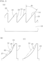
- the inclined surfaces 14 remain as they are as a part of the molded preform 22 that is transparent, and each have a well-light-transmissible homogeneous flat surface as shown in Fig. 3A .
- the inclined surfaces 14 are flat surfaces as described above, the inclined surfaces 14 includes cases even where the cross-section is a concave surface recessed inward 24, 25, and the cross-section is a concave surface making use of a part of a polygon as shown in Figs. 3B and 3C , not in accordance with the claimed invention.
- the concave surface 24 shown in Fig. 3B is configured by two flat surfaces 26, 27 in a manner where an angle ⁇ 2 formed by the flat surfaces 26, 27 becomes less than 180 degrees (e.g. 120 to 175 degrees, preferably the lower limit is 150 degrees and the upper limit is 170 degrees) .
- the concave surface 24 is configured by the two flat surfaces 26, 27, the concave surface may be configured by three or more of flat surfaces. In this case, angles formed by the flat surfaces next to each other may be identical or different.
- the concave surface 25 shown in Fig. 3C is configured by a curved surface which cross-section is bent or in a state of a circular arc.
- the concave surface is not limited to the above-mentioned shapes, but may be configured by combining a flat surface and a curved surface.
- the recessed amount of the concave surfaces 24, 25 to the inclined surfaces 14 may variously changed depending on conditions of the sputtering or other methods.
- lights L1 and L2 from an object obliquely entering from lower left side of the stereoscopic-image-forming device 10 respectively reflect at P1 and P2 of the lower vertical light-reflective surface 13, further reflect at Q1 and Q2 of the upper vertical light-reflective surface 13, and form a stereoscopic image in space on one side (the top side) of the stereoscopic-image-forming device 10.
- front sides left sides in Figs.
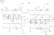
- metal reflective films (metal coatings) 28 formed on the vertical surfaces 23 by the mirror surface treatment are used as the vertical light-reflective surfaces 13 of the first and second light control panels 11; however, as shown in Figs. 2A and 2B , back sides (right sides in Figs. 2A and 2B ) of the metal reflective films 28 may be used as the vertical light-reflective surfaces 13.
- lights L3 and L4 from an object obliquely entering from lower right side of the stereoscopic-image-forming device 10 respectively enter into the lower transparent plate material 12 at R1 and S1, reflect at R2 and S2 of the lower vertical light-reflective surface 13, further reflect at R3 and S3 on the upper vertical light-reflective surface 13, exit from R4 and S4 of the upper transparent plate material 12, and form a stereoscopic image in space on the top side (one side) of the stereoscopic-image-forming device 10.
- the stereoscopic-image-forming device 10 In the operation of the stereoscopic-image-forming device 10, when the lights enter into the transparent plate material 12 from the air and when the lights exit from the transparent plate material 12 into the air, a refraction phenomenon or, according to the circumstances, a total reflection phenomenon of the lights may occur. Therefore, it is necessary to use the stereoscopic-image-forming device 10 while taking in consideration the possibility of occurrence of these phenomena. (It is also the case in embodiments below). Incidentally, the inclined surfaces 14 become light transmissive surfaces as they are.
- the cross-section of each of the protruded strips and grooves therebetween may be a rectangle or square shape; however, in this case, if the height-to-width ratio (height/width) is equal to or more than 1.5, the production (especially, the demolding) becomes difficult. Since each of the grooves 15 formed between the protruded strips 16 has a triangle-cross-section that width becomes narrower toward the bottom side, the production of the molded preform 22 by injection-molding becomes easier.
- a production method for the stereoscopic-image-forming device 10 is explained with reference to Figs. 4A to 4D . Note that since the production methods for the second light control panel 11 and the first light control panel 11 are the same, the production method for the first light control panel 11 is mainly explained.
- the molded preform 22, where the triangle-cross-section grooves 15 each having the vertical surface 23 and the inclined surface 14 and the protruded strips 16 formed by the grooves 15 next to each other are respectively arranged in parallel on one side (top side) of the transparent plate material 12, is produced by any one of press-molding, injection-molding and roll-molding.
- the annealing treatment is performed by, e.g., placing the molded preform 22 in an electric furnace, a hot air dryer or a hot water bath (heated solvent) for a predetermined time length (It is also the case in embodiments below; hereinbefore: a first step).
- the mirror surfaces are selectively formed only on the vertical surfaces 23 by a method shown in Fig. 4B , e.g., by sputtering.
- the sputtering is a technology in which an inert gas (mainly argon) is introduced in a vacuum, a negative voltage is applied to a target to cause a glow discharge, the inert gas atoms are ionized (or, in a non-ionized atomic state), the gas ions are bombarded to the surface of the target at a high speed, metal particles of film forming material constituting the target (e.g.
- the metal reflective films (metal coatings) 28 are formed on the surfaces of the vertical surfaces 23 as described above, thereby the vertical surfaces 23 become the vertical light-reflective surfaces 13, and the molded preform becomes an intermediate preform 30. Incidentally, forming the protruded strips having the concave surfaces is easy.
- the coating film it can be selected from coating films that are removable (i) by chemicals (solvents), (ii) by ultraviolet irradiation from the back side, or (iii) by heating up to a temperature with which the molded preform does not deform (Hereinbefore: a second step).
- the transparent resin 17 is filled up into the grooves 15 of the intermediate preform 30, and a flattening treatment to the filled surface 18 is applied to form a surface (a top surface) 31.
- a transparent resin that is the same as the material of the molded preform 22 or a transparent resin having a refractive index close to that of the molded preform 22 be used.
- the position of the surface 31 may be matched the level of the micro flat portions 21.
- the first light control panel 11 is thereby completed.
- the second light control panel 11 is produced with the same configuration and steps as the first light control panel 11.
- the respective surfaces 31 of the first and second light control panels 11 are bonded together (overlapped each other) in vacuum in a manner where the respective sides (the one sides, the front sides), on which the protruded strips 16 are formed, of the first and second light control panels 11 face to each other and abut on or proximate to each other such that the respective light-reflective surfaces 13 of the first and second light control panels 11 are orthogonally crossed or crossed (e.g. within a range of 88 to 92 degrees) in a plan view.
- the distance C between the micro flat surfaces 21 on the protruded strips 16 of the first light control panel 11 and the micro flat surfaces 21 on the protruded strips 16 of the second light control panel 11 is, e.g., exceeding 0, and equal to or less than 5 mm, approximately.
- the stereoscopic-image-forming device 10 is thereby completed.
- the first and second light control panels 11 are bonded together in a manner where the respective sides on which the protruded strips 16 are provided abut on or proximate to each other; however, the stereoscopic-image-forming device may be configured by making the respective transparent plate materials 12 (the back sides) abut on each other, or by making the side on which the protruded strip 16 are provided of the first light control panel 11 and the transparent plate material 12 of the second light control panel 11 (or vice versa) abut on each other (hereinbefore: a third step).
- a stereoscopic-image-forming device 40 and a production method for the same according to the present invention will be explained below.
- the first and second light control panels 11 are separately produced and overlapped each other to form the stereoscopic-image-forming device 10.
- grooves 42, 43 and protruded strips 44, 45 formed on the front and back surfaces (both surfaces) of a transparent plate material 41 are integrally formed by dies.
- triangle-cross-section grooves 42 each having a vertical surface 46 and an inclined surface 47 and triangle-cross-section protruded strips 44 (first protruded strips) formed by the grooves 42 next to each other are respectively arranged in parallel on one side of the transparent plate material (having a thickness h3) 41 positioned in the middle.
- triangle-cross-section grooves 43 each having a vertical surface 48 and an inclined surface 49 and triangle-cross-section protruded strips 45 (second protruded strips) formed by the grooves 43 next to each other are respectively arranged in parallel on the other side of the transparent plate material 41.
- a molded preform 50 is produced by any one of press-molding, injection-molding and roll-molding such that the grooves 42 formed on one side of the transparent plate material 41 and the grooves 43 formed on the other side of the transparent plate material 41 are orthogonally crossed or crossed in a plan view with an angle of e.g. 85 to 95 degrees, preferably 88 to 92 degrees.
- the molded preform 50 is made from a transparent resin (first transparent resin) as same as the molded preform 22.
- micro flat portions are provided as same as the above-described stereoscopic-image-forming device 10.
- the material, production method, and specifications (dimensions h2 and ⁇ 1) of the molded preform 50 are the same as those of the stereoscopic-image-forming device 10.
- the thickness (h3) of the transparent plate material 41 is twice the thickness (h1) of the transparent plate material 12 (hereinbefore: a first step).
- vertical light-reflective surfaces 51, 52 that are the mirror surfaces are selectively formed by performing the mirror surface treatment only to vertical surfaces 46 of the grooves 42 and vertical surfaces 48 of the grooves 43 respectively provided on the both sides of the transparent plate material 41, as mentioned above, by metal deposition, sputtering, or according to the circumstances, spraying metal microparticles or ion beam irradiation (an intermediate molded preform, hereinbefore: a second step).
- the stereoscopic-image-forming device 40 in a state of a flat plate having the first and second light control panels which exposed surfaces are flat surfaces formed on the front and back sides thereof is made by filling up the grooves 42, 43 of the intermediate molded preform with a transparent resin 53, 54 (the second transparent resin) and applying the flattening treatment to the filled surfaces (hereinbefore: a third step).
- Fig. 6 that shows the stereoscopic-image-forming device 10 in a plan view (the stereoscopic-image-forming device 40 is also the same), the vertical light-reflective surfaces 13 are arranged with an angle of 40 to 50 degrees in a plan view with respect to an outer frame 55 having a shape of a rectangle or a square.
- the present invention is not limited to the above-mentioned embodiments, and the present invention is applied also in the cases where the elements of or the production methods for the stereoscopic-image-forming device according to each of the embodiments are combined to configure or produce a stereoscopic-image-forming device.
- the vertical light-reflective surfaces are formed on the both sides of each of the metal coatings.
- the flattening treatment includes the cases of forming by cutting or polishing as well as pushing by presses or else and molding by dies.
- the production method for a stereoscopic-image-forming device and the stereoscopic-image-forming device according to the present invention enable a stereoscopic-image-forming device which aspect ratio is relatively high to be easily and inexpensively produced. Therefore, the stereoscopic-image-forming device can be effectively utilized for appliances that require an image (e.g. medical appliances, home appliances, motor vehicles, aircrafts, vessels, or else).
- appliances e.g. medical appliances, home appliances, motor vehicles, aircrafts, vessels, or else).
Landscapes
- Physics & Mathematics (AREA)
- General Physics & Mathematics (AREA)
- Optics & Photonics (AREA)
- Engineering & Computer Science (AREA)
- Mechanical Engineering (AREA)
- Manufacturing & Machinery (AREA)
- Health & Medical Sciences (AREA)
- Ophthalmology & Optometry (AREA)
- Optical Elements Other Than Lenses (AREA)
- Stereoscopic And Panoramic Photography (AREA)
Claims (3)
- Procédé de production pour un dispositif de formation d'images stéréoscopiques (40) caractérisé en ce qu'il comprend:une première étape de production d'une préforme moulée (50) faite d'une première résine transparente par moulage par injection, la préforme moulée (50) incluant des première et deuxième rainures (42, 43) à section transversale triangulaire formées respectivement des deux côtés d'un matériau en plaque transparent (41), la préforme moulée (50) incluant des première et deuxième bandes saillantes (44, 45) à section transversale triangulaire formées respectivement des deux côtés du matériau en plaque transparent (41), les première et deuxième rainures (42, 43) ayant chacune une surface verticale (46, 48) et une surface inclinée (47, 49) avec un angle (θ1) entre elles de 15 à 60 degrés, les premières bandes saillantes (44) étant formées par les premières rainures (42) les unes à côté des autres, les deuxièmes bandes saillantes (45) étant formées par les deuxièmes rainures (43) les unes à côté des autres, les première et deuxième rainures (42, 43) formées respectivement des deux côtés du matériau en plaque transparent (41) étant disposées de manière à être croisées orthogonalement dans une vue en plan;une deuxième étape de formation de surfaces de miroir (51, 52) sélectivement sur les surfaces verticales (46, 48) des première et deuxième rainures (42, 43) prévues des deux côtés de la préforme moulée (50); etune troisième étape d'introduction d'une deuxième résine transparente (53, 54) dans les première et deuxième rainures (42, 43) après la réalisation de la deuxième étape, et d'application en outre d'un traitement d'aplatissement à la surface de la deuxième résine transparente (53, 54) introduite,dans lequel, dans la deuxième étape, les surfaces de miroir (51, 52) sont formées par pulvérisation cathodique, dépôt de métal, pulvérisation de microparticules métalliques ou irradiation par faisceau ionique vers les surfaces verticales (46, 48) à partir d'une direction le long des surfaces inclinées (47, 49) de manière que les surfaces inclinées (47, 49) deviennent dans l'ombre, etdans lequel un indice de réfraction η2 de la deuxième résine transparente (53, 54) est dans une plage de 0,95 à 1,05 fois un indice de réfraction η1 de la première résine transparente.
- Procédé de production pour un dispositif de formation d'images stéréoscopiques selon la revendication 1, dans lequel les surfaces inclinées (47, 49) sont des surfaces planes.
- Procédé de production pour un dispositif de formation d'images stéréoscopiques selon la revendication 1, dans lequel un traitement de recuit pour éliminer les contraintes résiduelles est appliqué à la préforme moulée (50) après sa formation.
Applications Claiming Priority (3)
| Application Number | Priority Date | Filing Date | Title |
|---|---|---|---|
| JP2017013351 | 2017-01-27 | ||
| PCT/JP2017/005727 WO2018138932A1 (fr) | 2017-01-27 | 2017-02-16 | Procédé de fabrication de dispositif de formation d'image stéréoscopique, et dispositif de formation d'image stéréoscopique |
| PCT/JP2017/012622 WO2018138940A1 (fr) | 2017-01-27 | 2017-03-28 | Procédé de fabrication de dispositif de formation d'image stéréoscopique, et dispositif de formation d'image stéréoscopique |
Publications (3)
| Publication Number | Publication Date |
|---|---|
| EP3575853A1 EP3575853A1 (fr) | 2019-12-04 |
| EP3575853A4 EP3575853A4 (fr) | 2020-12-23 |
| EP3575853B1 true EP3575853B1 (fr) | 2024-12-25 |
Family
ID=62978397
Family Applications (1)
| Application Number | Title | Priority Date | Filing Date |
|---|---|---|---|
| EP17893968.2A Active EP3575853B1 (fr) | 2017-01-27 | 2017-03-28 | Procédé de fabrication de dispositif de formation d'image stéréoscopique, et dispositif de formation d'image stéréoscopique |
Country Status (7)
| Country | Link |
|---|---|
| US (1) | US20200001556A1 (fr) |
| EP (1) | EP3575853B1 (fr) |
| JP (4) | JP6667677B2 (fr) |
| KR (2) | KR102219750B1 (fr) |
| CN (1) | CN109997068B (fr) |
| RU (1) | RU2719349C1 (fr) |
| WO (2) | WO2018138932A1 (fr) |
Families Citing this family (9)
| Publication number | Priority date | Publication date | Assignee | Title |
|---|---|---|---|---|
| US9164625B2 (en) | 2012-10-14 | 2015-10-20 | Neonode Inc. | Proximity sensor for determining two-dimensional coordinates of a proximal object |
| US10282034B2 (en) | 2012-10-14 | 2019-05-07 | Neonode Inc. | Touch sensitive curved and flexible displays |
| EP3633436B1 (fr) * | 2017-06-01 | 2023-07-12 | Asukanet Company, Ltd. | Procédé de fabrication de dispositif de formation d'image stéréoscopique, et dispositif de formation d'image stéréoscopique |
| KR102797047B1 (ko) | 2019-12-31 | 2025-04-21 | 네오노드, 인크. | 비 접촉식 터치 입력 시스템 |
| CN114624797B (zh) * | 2020-12-09 | 2024-05-28 | 亚斯卡奈特股份有限公司 | 光学成像装置的制造方法以及光反射元件形成体 |
| JP7535018B2 (ja) * | 2021-07-26 | 2024-08-15 | 株式会社アスカネット | 空中像結像装置の製造方法及び空中像結像装置 |
| WO2023007816A1 (fr) | 2021-07-26 | 2023-02-02 | 株式会社アスカネット | Procédé de fabrication d'un dispositif de formation d'image aérienne, et dispositif de formation d'image aérienne |
| JP7117473B1 (ja) | 2021-07-26 | 2022-08-12 | 株式会社アスカネット | 空中像結像装置の製造方法 |
| JP2023156707A (ja) * | 2022-04-13 | 2023-10-25 | マクセル株式会社 | 空間浮遊映像表示システムおよび空間浮遊映像処理システム |
Citations (1)
| Publication number | Priority date | Publication date | Assignee | Title |
|---|---|---|---|---|
| WO2009131128A1 (fr) * | 2008-04-22 | 2009-10-29 | Fujishima Tomohiko | Dispositif d’imagerie optique et procede d’imagerie optique mettant en œuvre ce dispositif |
Family Cites Families (32)
| Publication number | Priority date | Publication date | Assignee | Title |
|---|---|---|---|---|
| JPS59214026A (ja) * | 1983-05-19 | 1984-12-03 | Toshio Masukane | 立体視再生方法と再生物 |
| US5822120A (en) * | 1996-02-05 | 1998-10-13 | Palazzotto; Michael C. | Layered retroreflective elements |
| JPH10197704A (ja) * | 1997-01-10 | 1998-07-31 | Denso Corp | 反射防止板の製造方法 |
| JP5027969B2 (ja) * | 2001-08-27 | 2012-09-19 | 大日本印刷株式会社 | 二次元視野拡大部材の製造方法 |
| GB2405542A (en) * | 2003-08-30 | 2005-03-02 | Sharp Kk | Multiple view directional display having display layer and parallax optic sandwiched between substrates. |
| EP2258560A3 (fr) * | 2003-11-21 | 2011-04-13 | Visual Physics, LLC | Sécurité micro-optique et système de présentation d'images |
| KR100586221B1 (ko) * | 2005-05-09 | 2006-06-07 | (주)실리콘화일 | 평면 표시 장치를 이용한 3차원 영상 표시 장치 |
| GB2431728A (en) * | 2005-10-31 | 2007-05-02 | Sharp Kk | Multi-depth displays |
| JP5414224B2 (ja) * | 2007-10-19 | 2014-02-12 | 富士フイルム株式会社 | 面状照明装置 |
| JP2010122382A (ja) * | 2008-11-18 | 2010-06-03 | Fujifilm Corp | 偏光変換素子及び該偏光変換素子を備える表示装置 |
| TWM368805U (en) * | 2009-07-03 | 2009-11-11 | Teng Luo Technology Co Ltd | Device for displaying 3D images |
| US20120099200A1 (en) * | 2009-07-17 | 2012-04-26 | Nippon Carbide Industries Co., Inc. | Retroreflective sheeting of micro glass sphere provided with image having visual direction |
| JP5085631B2 (ja) * | 2009-10-21 | 2012-11-28 | 株式会社アスカネット | 光学結像装置及びそれを用いた光学結像方法 |
| TWM388651U (en) * | 2010-03-18 | 2010-09-11 | Dayu Optoelectronics Co Ltd | Optical retroreflective apparatus |
| US8953124B2 (en) * | 2010-04-28 | 2015-02-10 | Sharp Kabushiki Kaisha | Optical system |
| JP2012198264A (ja) * | 2011-03-18 | 2012-10-18 | Seiko Epson Corp | 導光板の製造方法及び導光板並びに導光板を備える虚像表示装置 |
| JP2012215757A (ja) * | 2011-04-01 | 2012-11-08 | Seiko Epson Corp | スクリーン、及びスクリーンの製造方法 |
| JP4973794B1 (ja) * | 2011-04-06 | 2012-07-11 | ソニー株式会社 | 表示装置 |
| JP5728748B2 (ja) * | 2011-05-25 | 2015-06-03 | 国立研究開発法人情報通信研究機構 | リフレクタアレイ光学装置およびそれを用いた表示装置 |
| JP5995131B2 (ja) * | 2011-11-25 | 2016-09-21 | 大日本印刷株式会社 | 光学パネルおよび表示装置 |
| US9523859B2 (en) * | 2012-02-28 | 2016-12-20 | Asukanet Company, Ltd. | Volumetric-image forming system and method thereof |
| JP2014066825A (ja) * | 2012-09-25 | 2014-04-17 | Nitto Denko Corp | マイクロミラーアレイの製法 |
| US9715117B2 (en) * | 2012-10-31 | 2017-07-25 | G. B. Kirby Meacham | Autostereoscopic three dimensional display |
| US20150234099A1 (en) * | 2012-11-08 | 2015-08-20 | Asukanet Company, Ltd. | Method for producing light control panel |
| US20150336340A1 (en) * | 2013-09-06 | 2015-11-26 | Asukanet Company, Ltd. | Method for producing a light control panel provided with parallelly-arranged light-reflective portions |
| JP6076892B2 (ja) * | 2013-12-13 | 2017-02-08 | 株式会社アスカネット | 光学結像装置に使用する光制御パネルの製造方法 |
| JP6105465B2 (ja) * | 2013-12-27 | 2017-03-29 | 株式会社アスカネット | 立体像形成装置の製造方法 |
| JP2015200782A (ja) * | 2014-04-08 | 2015-11-12 | キヤノン株式会社 | 結像光学素子、結像光学系、及びそれを用いた画像読取装置 |
| JP6357361B2 (ja) * | 2014-06-18 | 2018-07-11 | 株式会社アスカネット | 再帰性反射体及びこれを利用した立体像表示装置 |
| JP5820955B1 (ja) * | 2014-06-27 | 2015-11-24 | 株式会社アスカネット | 再帰性反射体並びにこれを利用した立体像表示装置 |
| CN107111144A (zh) * | 2014-11-11 | 2017-08-29 | 夏普株式会社 | 导光板及虚像显示装置 |
| JP6446335B2 (ja) * | 2015-06-17 | 2018-12-26 | コニカミノルタ株式会社 | 結像光学素子およびその製造方法 |
-
2017
- 2017-02-16 JP JP2018564089A patent/JP6667677B2/ja active Active
- 2017-02-16 WO PCT/JP2017/005727 patent/WO2018138932A1/fr not_active Ceased
- 2017-03-28 KR KR1020207038046A patent/KR102219750B1/ko active Active
- 2017-03-28 CN CN201780073437.XA patent/CN109997068B/zh active Active
- 2017-03-28 US US16/480,038 patent/US20200001556A1/en not_active Abandoned
- 2017-03-28 RU RU2019126024A patent/RU2719349C1/ru active
- 2017-03-28 KR KR1020197022945A patent/KR102219748B1/ko active Active
- 2017-03-28 EP EP17893968.2A patent/EP3575853B1/fr active Active
- 2017-03-28 WO PCT/JP2017/012622 patent/WO2018138940A1/fr not_active Ceased
- 2017-08-29 JP JP2017164189A patent/JP6505175B2/ja active Active
-
2019
- 2019-02-13 JP JP2019023575A patent/JP6878477B2/ja active Active
-
2020
- 2020-01-16 JP JP2020005240A patent/JP6924855B2/ja active Active
Patent Citations (1)
| Publication number | Priority date | Publication date | Assignee | Title |
|---|---|---|---|---|
| WO2009131128A1 (fr) * | 2008-04-22 | 2009-10-29 | Fujishima Tomohiko | Dispositif d’imagerie optique et procede d’imagerie optique mettant en œuvre ce dispositif |
Also Published As
| Publication number | Publication date |
|---|---|
| CN109997068A (zh) | 2019-07-09 |
| WO2018138940A1 (fr) | 2018-08-02 |
| KR102219750B1 (ko) | 2021-02-23 |
| JP2020074028A (ja) | 2020-05-14 |
| WO2018138932A1 (fr) | 2018-08-02 |
| JP6505175B2 (ja) | 2019-04-24 |
| JP2019109530A (ja) | 2019-07-04 |
| EP3575853A1 (fr) | 2019-12-04 |
| CN109997068B (zh) | 2021-08-10 |
| US20200001556A1 (en) | 2020-01-02 |
| JPWO2018138932A1 (ja) | 2020-03-19 |
| EP3575853A4 (fr) | 2020-12-23 |
| JP2018124534A (ja) | 2018-08-09 |
| KR20190103311A (ko) | 2019-09-04 |
| JP6667677B2 (ja) | 2020-03-18 |
| JP6878477B2 (ja) | 2021-05-26 |
| KR102219748B1 (ko) | 2021-02-23 |
| RU2719349C1 (ru) | 2020-04-17 |
| KR20210002769A (ko) | 2021-01-08 |
| JP6924855B2 (ja) | 2021-08-25 |
Similar Documents
| Publication | Publication Date | Title |
|---|---|---|
| EP3575853B1 (fr) | Procédé de fabrication de dispositif de formation d'image stéréoscopique, et dispositif de formation d'image stéréoscopique | |
| JP6203989B1 (ja) | 立体像結像装置の製造方法 | |
| JP2019109530A5 (fr) | ||
| JP2018124534A5 (fr) | ||
| KR101721460B1 (ko) | 평행 배치된 광반사부를 구비한 광제어 패널의 제조 방법 | |
| US20150234099A1 (en) | Method for producing light control panel | |
| CN110476106B (zh) | 立体像成像装置 | |
| EP3647858B1 (fr) | Dispositif de formation d'image stéréoscopique et procédé de fabrication de dispositif de formation d'image stéréoscopique | |
| WO2017043456A1 (fr) | Procédé de fabrication de panneau de commande optique, panneau de commande optique, dispositif d'imagerie optique, et système de formation d'image spatiale | |
| US20240411150A1 (en) | Production method for stereoscopic-image-forming device, and stereoscopic-image-forming device | |
| JP2006524829A (ja) | 複数の高分子材料から成る複数の透明な光学素子を製造するための方法および型 | |
| CN110709759B (zh) | 立体像成像装置的制造方法以及立体像成像装置 | |
| JP2021081451A (ja) | 光制御パネルの製造方法及び立体像結像装置の製造方法 | |
| JP6357361B2 (ja) | 再帰性反射体及びこれを利用した立体像表示装置 | |
| EP4043945B1 (fr) | Dispositif de formation d'image optique et son procédé de fabrication | |
| JP6686184B2 (ja) | 立体像結像装置の製造方法及び立体像結像装置 | |
| JP6105465B2 (ja) | 立体像形成装置の製造方法 | |
| EP4379455A1 (fr) | Procédé de fabrication d'un dispositif de formation d'image aérienne, et dispositif de formation d'image aérienne | |
| JP6246704B2 (ja) | 再帰性反射体の製造型の製造方法 | |
| JP2022112787A (ja) | 立体像結像装置の製造方法 |
Legal Events
| Date | Code | Title | Description |
|---|---|---|---|
| STAA | Information on the status of an ep patent application or granted ep patent |
Free format text: STATUS: THE INTERNATIONAL PUBLICATION HAS BEEN MADE |
|
| PUAI | Public reference made under article 153(3) epc to a published international application that has entered the european phase |
Free format text: ORIGINAL CODE: 0009012 |
|
| STAA | Information on the status of an ep patent application or granted ep patent |
Free format text: STATUS: REQUEST FOR EXAMINATION WAS MADE |
|
| 17P | Request for examination filed |
Effective date: 20190827 |
|
| AK | Designated contracting states |
Kind code of ref document: A1 Designated state(s): AL AT BE BG CH CY CZ DE DK EE ES FI FR GB GR HR HU IE IS IT LI LT LU LV MC MK MT NL NO PL PT RO RS SE SI SK SM TR |
|
| REG | Reference to a national code |
Ref country code: DE Free format text: PREVIOUS MAIN CLASS: G02B0027220000 Ipc: B29C0045000000 Ref country code: DE Ref legal event code: R079 Ref document number: 602017087006 Country of ref document: DE Free format text: PREVIOUS MAIN CLASS: G02B0027220000 Ipc: B29C0045000000 |
|
| A4 | Supplementary search report drawn up and despatched |
Effective date: 20201120 |
|
| RIC1 | Information provided on ipc code assigned before grant |
Ipc: G02B 30/35 20200101ALI20201116BHEP Ipc: G02B 30/56 20200101ALI20201116BHEP Ipc: G02B 5/08 20060101ALI20201116BHEP Ipc: G03B 35/18 20060101ALI20201116BHEP Ipc: B29C 45/00 20060101AFI20201116BHEP |
|
| STAA | Information on the status of an ep patent application or granted ep patent |
Free format text: STATUS: EXAMINATION IS IN PROGRESS |
|
| 17Q | First examination report despatched |
Effective date: 20230127 |
|
| GRAP | Despatch of communication of intention to grant a patent |
Free format text: ORIGINAL CODE: EPIDOSNIGR1 |
|
| STAA | Information on the status of an ep patent application or granted ep patent |
Free format text: STATUS: GRANT OF PATENT IS INTENDED |
|
| INTG | Intention to grant announced |
Effective date: 20240820 |
|
| GRAS | Grant fee paid |
Free format text: ORIGINAL CODE: EPIDOSNIGR3 |
|
| GRAA | (expected) grant |
Free format text: ORIGINAL CODE: 0009210 |
|
| STAA | Information on the status of an ep patent application or granted ep patent |
Free format text: STATUS: THE PATENT HAS BEEN GRANTED |
|
| AK | Designated contracting states |
Kind code of ref document: B1 Designated state(s): AL AT BE BG CH CY CZ DE DK EE ES FI FR GB GR HR HU IE IS IT LI LT LU LV MC MK MT NL NO PL PT RO RS SE SI SK SM TR |
|
| P01 | Opt-out of the competence of the unified patent court (upc) registered |
Free format text: CASE NUMBER: APP_61966/2024 Effective date: 20241120 |
|
| REG | Reference to a national code |
Ref country code: GB Ref legal event code: FG4D |
|
| REG | Reference to a national code |
Ref country code: CH Ref legal event code: EP |
|
| REG | Reference to a national code |
Ref country code: DE Ref legal event code: R096 Ref document number: 602017087006 Country of ref document: DE |
|
| REG | Reference to a national code |
Ref country code: IE Ref legal event code: FG4D |
|
| REG | Reference to a national code |
Ref country code: LT Ref legal event code: MG9D |
|
| PG25 | Lapsed in a contracting state [announced via postgrant information from national office to epo] |
Ref country code: HR Free format text: LAPSE BECAUSE OF FAILURE TO SUBMIT A TRANSLATION OF THE DESCRIPTION OR TO PAY THE FEE WITHIN THE PRESCRIBED TIME-LIMIT Effective date: 20241225 |
|
| PG25 | Lapsed in a contracting state [announced via postgrant information from national office to epo] |
Ref country code: FI Free format text: LAPSE BECAUSE OF FAILURE TO SUBMIT A TRANSLATION OF THE DESCRIPTION OR TO PAY THE FEE WITHIN THE PRESCRIBED TIME-LIMIT Effective date: 20241225 |
|
| PG25 | Lapsed in a contracting state [announced via postgrant information from national office to epo] |
Ref country code: BG Free format text: LAPSE BECAUSE OF FAILURE TO SUBMIT A TRANSLATION OF THE DESCRIPTION OR TO PAY THE FEE WITHIN THE PRESCRIBED TIME-LIMIT Effective date: 20241225 |
|
| PG25 | Lapsed in a contracting state [announced via postgrant information from national office to epo] |
Ref country code: NO Free format text: LAPSE BECAUSE OF FAILURE TO SUBMIT A TRANSLATION OF THE DESCRIPTION OR TO PAY THE FEE WITHIN THE PRESCRIBED TIME-LIMIT Effective date: 20250325 |
|
| PG25 | Lapsed in a contracting state [announced via postgrant information from national office to epo] |
Ref country code: GR Free format text: LAPSE BECAUSE OF FAILURE TO SUBMIT A TRANSLATION OF THE DESCRIPTION OR TO PAY THE FEE WITHIN THE PRESCRIBED TIME-LIMIT Effective date: 20250326 Ref country code: LV Free format text: LAPSE BECAUSE OF FAILURE TO SUBMIT A TRANSLATION OF THE DESCRIPTION OR TO PAY THE FEE WITHIN THE PRESCRIBED TIME-LIMIT Effective date: 20241225 |
|
| PG25 | Lapsed in a contracting state [announced via postgrant information from national office to epo] |
Ref country code: RS Free format text: LAPSE BECAUSE OF FAILURE TO SUBMIT A TRANSLATION OF THE DESCRIPTION OR TO PAY THE FEE WITHIN THE PRESCRIBED TIME-LIMIT Effective date: 20250325 |
|
| REG | Reference to a national code |
Ref country code: NL Ref legal event code: MP Effective date: 20241225 |
|
| PG25 | Lapsed in a contracting state [announced via postgrant information from national office to epo] |
Ref country code: NL Free format text: LAPSE BECAUSE OF FAILURE TO SUBMIT A TRANSLATION OF THE DESCRIPTION OR TO PAY THE FEE WITHIN THE PRESCRIBED TIME-LIMIT Effective date: 20241225 |
|
| REG | Reference to a national code |
Ref country code: AT Ref legal event code: MK05 Ref document number: 1753804 Country of ref document: AT Kind code of ref document: T Effective date: 20241225 |
|
| PG25 | Lapsed in a contracting state [announced via postgrant information from national office to epo] |
Ref country code: SM Free format text: LAPSE BECAUSE OF FAILURE TO SUBMIT A TRANSLATION OF THE DESCRIPTION OR TO PAY THE FEE WITHIN THE PRESCRIBED TIME-LIMIT Effective date: 20241225 |
|
| PG25 | Lapsed in a contracting state [announced via postgrant information from national office to epo] |
Ref country code: PL Free format text: LAPSE BECAUSE OF FAILURE TO SUBMIT A TRANSLATION OF THE DESCRIPTION OR TO PAY THE FEE WITHIN THE PRESCRIBED TIME-LIMIT Effective date: 20241225 |
|
| PG25 | Lapsed in a contracting state [announced via postgrant information from national office to epo] |
Ref country code: ES Free format text: LAPSE BECAUSE OF FAILURE TO SUBMIT A TRANSLATION OF THE DESCRIPTION OR TO PAY THE FEE WITHIN THE PRESCRIBED TIME-LIMIT Effective date: 20241225 |
|
| PG25 | Lapsed in a contracting state [announced via postgrant information from national office to epo] |
Ref country code: IS Free format text: LAPSE BECAUSE OF FAILURE TO SUBMIT A TRANSLATION OF THE DESCRIPTION OR TO PAY THE FEE WITHIN THE PRESCRIBED TIME-LIMIT Effective date: 20250425 |
|
| PG25 | Lapsed in a contracting state [announced via postgrant information from national office to epo] |
Ref country code: PT Free format text: LAPSE BECAUSE OF FAILURE TO SUBMIT A TRANSLATION OF THE DESCRIPTION OR TO PAY THE FEE WITHIN THE PRESCRIBED TIME-LIMIT Effective date: 20250428 |
|
| PG25 | Lapsed in a contracting state [announced via postgrant information from national office to epo] |
Ref country code: EE Free format text: LAPSE BECAUSE OF FAILURE TO SUBMIT A TRANSLATION OF THE DESCRIPTION OR TO PAY THE FEE WITHIN THE PRESCRIBED TIME-LIMIT Effective date: 20241225 |
|
| PG25 | Lapsed in a contracting state [announced via postgrant information from national office to epo] |
Ref country code: RO Free format text: LAPSE BECAUSE OF FAILURE TO SUBMIT A TRANSLATION OF THE DESCRIPTION OR TO PAY THE FEE WITHIN THE PRESCRIBED TIME-LIMIT Effective date: 20241225 Ref country code: AT Free format text: LAPSE BECAUSE OF FAILURE TO SUBMIT A TRANSLATION OF THE DESCRIPTION OR TO PAY THE FEE WITHIN THE PRESCRIBED TIME-LIMIT Effective date: 20241225 |
|
| PG25 | Lapsed in a contracting state [announced via postgrant information from national office to epo] |
Ref country code: SK Free format text: LAPSE BECAUSE OF FAILURE TO SUBMIT A TRANSLATION OF THE DESCRIPTION OR TO PAY THE FEE WITHIN THE PRESCRIBED TIME-LIMIT Effective date: 20241225 |
|
| PG25 | Lapsed in a contracting state [announced via postgrant information from national office to epo] |
Ref country code: CZ Free format text: LAPSE BECAUSE OF FAILURE TO SUBMIT A TRANSLATION OF THE DESCRIPTION OR TO PAY THE FEE WITHIN THE PRESCRIBED TIME-LIMIT Effective date: 20241225 |
|
| PG25 | Lapsed in a contracting state [announced via postgrant information from national office to epo] |
Ref country code: IT Free format text: LAPSE BECAUSE OF FAILURE TO SUBMIT A TRANSLATION OF THE DESCRIPTION OR TO PAY THE FEE WITHIN THE PRESCRIBED TIME-LIMIT Effective date: 20241225 |
|
| PG25 | Lapsed in a contracting state [announced via postgrant information from national office to epo] |
Ref country code: SE Free format text: LAPSE BECAUSE OF FAILURE TO SUBMIT A TRANSLATION OF THE DESCRIPTION OR TO PAY THE FEE WITHIN THE PRESCRIBED TIME-LIMIT Effective date: 20241225 |
|
| REG | Reference to a national code |
Ref country code: DE Ref legal event code: R097 Ref document number: 602017087006 Country of ref document: DE |
|
| PG25 | Lapsed in a contracting state [announced via postgrant information from national office to epo] |
Ref country code: DK Free format text: LAPSE BECAUSE OF FAILURE TO SUBMIT A TRANSLATION OF THE DESCRIPTION OR TO PAY THE FEE WITHIN THE PRESCRIBED TIME-LIMIT Effective date: 20241225 |
|
| PG25 | Lapsed in a contracting state [announced via postgrant information from national office to epo] |
Ref country code: MC Free format text: LAPSE BECAUSE OF FAILURE TO SUBMIT A TRANSLATION OF THE DESCRIPTION OR TO PAY THE FEE WITHIN THE PRESCRIBED TIME-LIMIT Effective date: 20241225 |
|
| REG | Reference to a national code |
Ref country code: CH Ref legal event code: H13 Free format text: ST27 STATUS EVENT CODE: U-0-0-H10-H13 (AS PROVIDED BY THE NATIONAL OFFICE) Effective date: 20251024 |
|
| PLBE | No opposition filed within time limit |
Free format text: ORIGINAL CODE: 0009261 |
|
| STAA | Information on the status of an ep patent application or granted ep patent |
Free format text: STATUS: NO OPPOSITION FILED WITHIN TIME LIMIT |
|
| PG25 | Lapsed in a contracting state [announced via postgrant information from national office to epo] |
Ref country code: LU Free format text: LAPSE BECAUSE OF NON-PAYMENT OF DUE FEES Effective date: 20250328 |
|
| 26N | No opposition filed |
Effective date: 20250926 |
|
| REG | Reference to a national code |
Ref country code: BE Ref legal event code: MM Effective date: 20250331 |
|
| PG25 | Lapsed in a contracting state [announced via postgrant information from national office to epo] |
Ref country code: BE Free format text: LAPSE BECAUSE OF NON-PAYMENT OF DUE FEES Effective date: 20250331 |
|
| PG25 | Lapsed in a contracting state [announced via postgrant information from national office to epo] |
Ref country code: CH Free format text: LAPSE BECAUSE OF NON-PAYMENT OF DUE FEES Effective date: 20250331 |
|
| PG25 | Lapsed in a contracting state [announced via postgrant information from national office to epo] |
Ref country code: IE Free format text: LAPSE BECAUSE OF NON-PAYMENT OF DUE FEES Effective date: 20250328 |
|
| PGFP | Annual fee paid to national office [announced via postgrant information from national office to epo] |
Ref country code: GB Payment date: 20260324 Year of fee payment: 10 |
|
| PGFP | Annual fee paid to national office [announced via postgrant information from national office to epo] |
Ref country code: DE Payment date: 20260319 Year of fee payment: 10 |
|
| PGFP | Annual fee paid to national office [announced via postgrant information from national office to epo] |
Ref country code: FR Payment date: 20260320 Year of fee payment: 10 |