WO2017043456A1 - Procédé de fabrication de panneau de commande optique, panneau de commande optique, dispositif d'imagerie optique, et système de formation d'image spatiale - Google Patents
Procédé de fabrication de panneau de commande optique, panneau de commande optique, dispositif d'imagerie optique, et système de formation d'image spatiale Download PDFInfo
- Publication number
- WO2017043456A1 WO2017043456A1 PCT/JP2016/076061 JP2016076061W WO2017043456A1 WO 2017043456 A1 WO2017043456 A1 WO 2017043456A1 JP 2016076061 W JP2016076061 W JP 2016076061W WO 2017043456 A1 WO2017043456 A1 WO 2017043456A1
- Authority
- WO
- WIPO (PCT)
- Prior art keywords
- glass
- control panel
- light control
- adhesive
- manufacturing
- Prior art date
Links
Images

Classifications
-
- G—PHYSICS
- G02—OPTICS
- G02B—OPTICAL ELEMENTS, SYSTEMS OR APPARATUS
- G02B5/00—Optical elements other than lenses
- G02B5/08—Mirrors
- G02B5/0816—Multilayer mirrors, i.e. having two or more reflecting layers
-
- C—CHEMISTRY; METALLURGY
- C03—GLASS; MINERAL OR SLAG WOOL
- C03C—CHEMICAL COMPOSITION OF GLASSES, GLAZES OR VITREOUS ENAMELS; SURFACE TREATMENT OF GLASS; SURFACE TREATMENT OF FIBRES OR FILAMENTS MADE FROM GLASS, MINERALS OR SLAGS; JOINING GLASS TO GLASS OR OTHER MATERIALS
- C03C27/00—Joining pieces of glass to pieces of other inorganic material; Joining glass to glass other than by fusing
- C03C27/06—Joining glass to glass by processes other than fusing
- C03C27/10—Joining glass to glass by processes other than fusing with the aid of adhesive specially adapted for that purpose
-
- G—PHYSICS
- G02—OPTICS
- G02B—OPTICAL ELEMENTS, SYSTEMS OR APPARATUS
- G02B17/00—Systems with reflecting surfaces, with or without refracting elements
- G02B17/002—Arrays of reflective systems
-
- G—PHYSICS
- G02—OPTICS
- G02B—OPTICAL ELEMENTS, SYSTEMS OR APPARATUS
- G02B17/00—Systems with reflecting surfaces, with or without refracting elements
- G02B17/006—Systems in which light light is reflected on a plurality of parallel surfaces, e.g. louvre mirrors, total internal reflection [TIR] lenses
-
- G—PHYSICS
- G02—OPTICS
- G02B—OPTICAL ELEMENTS, SYSTEMS OR APPARATUS
- G02B27/00—Optical systems or apparatus not provided for by any of the groups G02B1/00 - G02B26/00, G02B30/00
- G02B27/01—Head-up displays
- G02B27/0101—Head-up displays characterised by optical features
-
- G—PHYSICS
- G02—OPTICS
- G02B—OPTICAL ELEMENTS, SYSTEMS OR APPARATUS
- G02B30/00—Optical systems or apparatus for producing three-dimensional [3D] effects, e.g. stereoscopic images
- G02B30/50—Optical systems or apparatus for producing three-dimensional [3D] effects, e.g. stereoscopic images the image being built up from image elements distributed over a 3D volume, e.g. voxels
- G02B30/52—Optical systems or apparatus for producing three-dimensional [3D] effects, e.g. stereoscopic images the image being built up from image elements distributed over a 3D volume, e.g. voxels the 3D volume being constructed from a stack or sequence of 2D planes, e.g. depth sampling systems
-
- G—PHYSICS
- G02—OPTICS
- G02B—OPTICAL ELEMENTS, SYSTEMS OR APPARATUS
- G02B30/00—Optical systems or apparatus for producing three-dimensional [3D] effects, e.g. stereoscopic images
- G02B30/50—Optical systems or apparatus for producing three-dimensional [3D] effects, e.g. stereoscopic images the image being built up from image elements distributed over a 3D volume, e.g. voxels
- G02B30/56—Optical systems or apparatus for producing three-dimensional [3D] effects, e.g. stereoscopic images the image being built up from image elements distributed over a 3D volume, e.g. voxels by projecting aerial or floating images
-
- G—PHYSICS
- G02—OPTICS
- G02B—OPTICAL ELEMENTS, SYSTEMS OR APPARATUS
- G02B5/00—Optical elements other than lenses
- G02B5/08—Mirrors
- G02B5/0816—Multilayer mirrors, i.e. having two or more reflecting layers
- G02B5/085—Multilayer mirrors, i.e. having two or more reflecting layers at least one of the reflecting layers comprising metal
-
- G—PHYSICS
- G03—PHOTOGRAPHY; CINEMATOGRAPHY; ANALOGOUS TECHNIQUES USING WAVES OTHER THAN OPTICAL WAVES; ELECTROGRAPHY; HOLOGRAPHY
- G03B—APPARATUS OR ARRANGEMENTS FOR TAKING PHOTOGRAPHS OR FOR PROJECTING OR VIEWING THEM; APPARATUS OR ARRANGEMENTS EMPLOYING ANALOGOUS TECHNIQUES USING WAVES OTHER THAN OPTICAL WAVES; ACCESSORIES THEREFOR
- G03B35/00—Stereoscopic photography
- G03B35/18—Stereoscopic photography by simultaneous viewing
- G03B35/24—Stereoscopic photography by simultaneous viewing using apertured or refractive resolving means on screens or between screen and eye
-
- G—PHYSICS
- G02—OPTICS
- G02B—OPTICAL ELEMENTS, SYSTEMS OR APPARATUS
- G02B2207/00—Coding scheme for general features or characteristics of optical elements and systems of subclass G02B, but not including elements and systems which would be classified in G02B6/00 and subgroups
- G02B2207/123—Optical louvre elements, e.g. for directional light blocking
Definitions
- the present invention relates to a method of manufacturing a light control panel used in an optical imaging apparatus that forms an image in the air.
- an optical element for forming an image in the air a light control panel in which a large number of band-like reflecting surfaces are formed at a constant pitch in a direction perpendicular to the thickness direction is known.
- An optical imaging apparatus that forms an image in the air can be configured by using two of the light control panels and stacking the two light control panels so that the band-like reflection surfaces are substantially orthogonal to each other.
- Patent Document 1 describes a method for manufacturing a light control panel.
- a transparent sheet glass, transparent plastic, etc.
- a mirror sheet mirror sheet coated with a UV curable adhesive
- the light control panel is formed by cutting out to a certain thickness on the surface intersecting with.
- the transparent sheet and the mirror sheet are bonded to each other by a UV curable adhesive.
- an adhesive layer (adhesive layer made of a UV curable adhesive) is provided between adjacent glass pieces in a large number of glass pieces stacked.
- the light control panel is provided with a large number of adhesive layers. Therefore, many adhesives are required for manufacturing the light control panel, and it is difficult to manufacture the light control panel at a low cost.
- the present invention has been made in view of such circumstances, and an object thereof is to reduce the manufacturing cost of the light control panel by reducing the adhesive used in the manufacture of the light control panel.
- a method for manufacturing a light control panel according to the present invention is a method for manufacturing a light control panel in which a number of band-like reflecting surfaces are formed at a constant pitch in a direction perpendicular to the thickness direction.
- the transparent adhesive is applied to at least one of one side of the glass laminate or the transparent cover plate, and the adhesive is sandwiched between the glass laminate and the cover plate.
- a step of stacking the cover plate on one side of the glass laminate and a step of curing the adhesive between the glass laminate and the cover plate to form an adhesive layer may be provided.
- this manufacturing method is further provided with the cutting process which cut
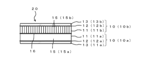
- the light control panel according to the present invention is a light control panel in which a large number of strip-like reflecting surfaces are formed at a constant pitch in a direction perpendicular to the thickness direction, and the shape is a flat plate having a thickness.
- One of the main surfaces facing in the vertical direction functions as a belt-like reflecting surface.
- the fixing portion of the light control panel is in contact with one side of the glass laminate, and is opposite to the glass laminate in the adhesive layer so as to cover the one side of the glass laminate and the adhesive layer composed of the cured transparent adhesive. You may have the transparent cover plate adhere
- the optical imaging apparatus includes the two light control panels described above, and the two light control panels have the respective strip-like reflecting surfaces substantially orthogonal to each other and the glass laminates face each other. And are bonded via a second adhesive layer.
- An aerial image forming system includes the above-described optical imaging device, and a playback device that is arranged on the back side of the optical imaging device and displays an image in a display based on electronic data, An aerial image is formed by forming an image in the display in a free space (in the air) on the front side of the optical imaging device.
- a flat glass laminate is produced by directly stacking a large number of elongated flat glass pieces.
- a conventional laminate of a large number of transparent sheets (a block body in which a mirror sheet is interposed between transparent sheets) is not cut out at a constant thickness, and a large number of stacked glass pieces are an element of a light control panel. It becomes the glass laminated body which is.
- many glass pieces are directly piled up. In the laminating step, no adhesive is provided between adjacent glass pieces. Therefore, since the adhesive can be reduced between the adjacent glass pieces 15 that conventionally used a large amount of adhesive, the manufacturing cost of the light control panel can be reduced.
- the transparent glass piece which does not have a metal reflective film (mirror) on both surfaces can be used.
- a metal reflective film mirror
- the transparent glass piece which does not have a metal reflective film (mirror) on both surfaces can be used.
- the transparent glass piece which does not have a metal reflective film (mirror) on both surfaces can be used.
- a minute gap is formed between adjacent glass pieces.
- light incident obliquely from the side surface of the glass piece is totally reflected on the main surface of the glass piece (surface facing the thickness direction) due to the difference in refractive index between the glass piece and the air in the minute gap. reflect.
- the metal reflecting film is not provided on both surfaces of the glass piece, the light for forming the aerial image is appropriately reflected, and the light control panel functions appropriately.
- the manufacturing cost of the light control panel can be further reduced.
- a glass laminate used for one light control panel is produced from a large number of glass pieces without producing a block body from which a plurality of light control panels are cut out as in the prior art.
- the glass laminate is lighter than the block body. For this reason, conventionally, it has been difficult to increase the size of the light control panel due to the restriction on the weight of the block body.
- the light control panel can be increased in size.
- a large number of glass pieces of the glass laminate can be integrated by fixing to a single cover plate with an adhesive layer.
- the adhesive layer adheres to the side surface of each glass piece and the cover plate. Therefore, even if it does not grind
- FIG. 1 is a side view of an optical imaging apparatus according to an embodiment.
- FIG. 2 is a diagram for describing formation of an aerial image using the optical imaging apparatus according to the embodiment.
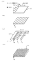
- FIG. 3 is a diagram for explaining a method of manufacturing the light control panel.
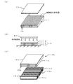
- FIG. 4 is a diagram for explaining a method of manufacturing the light control panel and the optical imaging device.
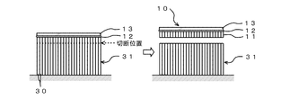
- FIG. 5 is a diagram for explaining a method of manufacturing the light control panel according to the modification.
- the light control panel 10 is an optical element in which a number of strip-like reflecting surfaces are formed at a constant pitch in a direction perpendicular to the thickness direction.
- the light control panel 10 includes a glass laminate 11, an adhesive layer 12 (first adhesive layer), and a cover plate 13.
- the glass laminate 11 is obtained by laminating a large number of glass pieces 15 in the horizontal direction.
- An adhesive layer 12 and a cover plate 13 are laminated on the glass laminate 11 in this order.
- the adhesive layer 12 and the cover plate 13 correspond to a fixing portion that integrates a large number of glass pieces 15 in the glass laminate 11. A large number of glass pieces 15 are fixed and integrated with each other.
- the glass laminate 11 is obtained by laminating a large number (for example, 100 or more) of glass pieces 15 (glass rods) having an elongated rectangular flat plate shape.
- the many glass pieces 15 have the same dimensions (the same shape and the same size), and are overlapped without being displaced from each other.
- the shape of the glass laminate 11 is a rectangular flat plate (flat rectangular parallelepiped) (see FIG. 3D).
- a large number of glass pieces 15 are directly superimposed in a direction perpendicular to the thickness direction.
- the adjacent glass pieces 15 are directly facing each other without any other member such as an adhesive.
- the pair of main surfaces (front and back surfaces opposed to each other in the thickness direction) of the glass laminate 11 are formed on a substantially flat surface by aligning the side surfaces (side surfaces on the long side) of many glass pieces 15. Yes.
- the dimensions of the glass piece 15 are a short side (width) of 1.5 mm, a long side (length) of 300 mm, and a thickness of 0.5 mm.
- the glass laminate 11 for example, 600 glass pieces 15 are overlaid.
- the glass laminate 11 is a rectangular parallelepiped having a square shape of about 300 mm ⁇ about 300 mm in plan view and a thickness of 1.5 mm.
- each dimension of the glass piece 15 and the glass laminated body 11 is not limited to the dimension described in this paragraph.
- the adhesive layer 12 is a thin and transparent layer in contact with one main surface of the glass laminate 11.
- the adhesive layer 12 is composed of an adhesive that is applied to one main surface of the glass laminate 11 and cured.
- the adhesive layer 12 fixes each glass piece 15 of the glass laminate 11 to the cover plate 13.
- the adhesive layer 12 covers one main surface of the glass laminate 11 over substantially the entire surface.
- the cover plate 13 is a rectangular flat thin and transparent glass.
- the thickness of the cover plate 13 is approximately the same as the thickness of the glass piece 15 and is thinner than the glass laminate 11.
- the cover plate 13 is, for example, substantially the same size as the main surface of the glass laminate 11, and is bonded to the opposite side of the glass laminate 11 in the adhesive layer 12 so as to cover the entire main surface. Yes.
- the cover plate 13 and the main surface of the glass laminate 11 have substantially parallel sides.
- each glass piece 15 constituting the main surface (front and back surfaces) of the glass laminate 11 is a cut surface cut in a cutting step described later, and is not polished. On the side surface of each glass piece 15, unevenness remains as a cut trace. However, when the adhesive layer 12 is in close contact with the side surface of each glass piece 15 and the cover plate 13, the side surface portion of each glass piece 15 in the glass laminate 11 can be made transparent. According to the present embodiment, polishing of one side surface of each glass piece 15 can be omitted.
- the optical imaging device 20 includes two light control panels 10.
- the optical imaging apparatus 20 in order to distinguish the two light control panels 10, "a" or "b" is used as a reference numeral for the light control panel 10 and its components. The attached reference numerals are used.
- the two light control panels 10a and 10b are arranged such that the glass laminates 11a and 11b face each other such that the belt-like reflection surfaces thereof are substantially orthogonal and the glass laminates 11a and 11b face each other.
- the adhesive layer 16 (second adhesive layer).
- the adhesive layer 16 is in close contact with the side surfaces of the glass pieces 15a, 15b of the glass laminates 11a, 11b. Therefore, the unpolished side surface portion can be made transparent. According to the present embodiment, polishing of the other side surface of each glass piece 15 can also be omitted.
- the angle formed by the band-shaped reflection surface of the light control panel 10a and the band-shaped reflection surface of the light control panel 10b may be, for example, 90 ° ⁇ 2 °.
- the aerial image forming system 25 includes an optical imaging device 20 and a reproduction device 26 arranged on the back side of the optical imaging device 20.
- the playback device 26 includes a display 27 that displays an aerial video based on electronic data.
- the display 27 can display a still image or a moving image.
- the display device 27 is positioned below the optical imaging device 20 and faces the optical imaging device 20 side.
- the light rays A and B from the point X of the display device 27 are regularly regularly reflected at the point P on the band-like reflecting surface of the light control panel 10a and the point Q on the band-like reflecting surface of the light control panel 10b. Then, the light rays A and B specularly reflected at the point Q gather at a point X ′ above the optical imaging apparatus 20.
- the light beams C and D from the point Y of the display device 27 are regularly regularly reflected at the point R on the band-like reflecting surface of the light control panel 10a and the point S on the band-like reflecting surface of the light control panel 10b. Then, the light rays C and D that are regularly reflected at the point S gather at a point Y ′ above the optical imaging apparatus 20. Therefore, an aerial image can be formed by forming an image in the display 27 in the free space on the front side of the optical imaging device 20.
- the aerial image forming system 25 can form a two-dimensional aerial image or a three-dimensional aerial image (stereoscopic image) according to the image in the display device 27.
- a two-dimensional aerial image for example, an aerial touch panel can be formed.
- a three-dimensional aerial image for example, a character can be formed.
- the manufacturing method of the light control panel 10 includes a cutting process, a cleaning process, a stacking process, and an integration process. A method for manufacturing the light control panel 10 will be described with reference to FIGS.
- FIG. 3 is a perspective view of all of (a) to (d).
- 4A and 4C are perspective views, and
- FIG. 4B is a side view.
- a rectangular flat plate-like transparent plate glass 30 (for example, a blue plate glass substrate) is installed on a flat installation surface as a material plate.
- a cutter 40 (for example, a laser cutter) exists above the transparent plate glass 30.
- a cutter capable of fully cutting the transparent plate glass 30 at a high speed for example, a straight portion 1 m / second
- a direction parallel to one of the two opposite sides of the transparent plate glass 30 is referred to as a “first direction”
- a direction parallel to the other is referred to as a “second direction”.
- the transparent plate glass 30 is moved from the end to the end by the cutter 40 while moving the cutter 40 in the first direction as shown in FIG. Disconnect. Subsequently, the position of the cutter 40 is shifted in the second direction by a predetermined set distance (a distance corresponding to the width of the glass piece 15), the transparent plate glass 30 is cut from end to end in the first direction, and again the set distance. Only the position of the cutter 40 is shifted in the second direction. The cutter 40 repeats “cutting in the first direction” and “shifting in the second direction” alternately. The cutter 40 gradually moves in the second direction while reciprocating. The cutting of the transparent plate glass 30 by the cutter 40 is performed at a constant pitch in the second direction. As a result, as shown in FIG. 3B, the transparent plate glass 30 is divided into a plurality of glass pieces 15 having the same width. A plurality of transparent plate glasses 30 are used for manufacturing one light control panel 10.
- the transparent plate glass 30 may be moved by a set distance in the second direction (left direction in FIG. 3A) instead of the cutter 40. After this movement, cutting in the first direction is performed.
- a plurality of cutters 40 arranged at a constant pitch in the second direction may be used. In this case, it is possible to cut a plurality of places at a time while moving the plurality of cutters 40 together.
- a cleaning process is performed to wash away the glass powder generated by cutting.
- the surface of each glass piece 15 obtained in the cutting step is washed away with a cleaning liquid, and the glass powder adhering to each glass piece 15 is removed.
- Each glass piece 15 is heat-dried after washing.
- a laminating process for producing the glass laminate 11 is performed by directly laminating a large number of elongated flat glass pieces 15.
- the glass pieces 15 so that the front and back surfaces of the original transparent plate glass 30 are laminated surfaces and the side surfaces (cut surfaces) of the glass pieces 15 are upper and lower surfaces.
- the glass plate 15 of a rectangular flat plate shape (refer FIG.3 (d)) is produced by aligning the edge of the longitudinal direction of the glass piece 15, and overlapping the glass piece 15. As shown in FIG. The last glass piece 15 is pressed against the inside of the glass laminate 11.
- a mold member 41 having at least two wall surfaces 41a and 41b orthogonal to each other can be used.
- the glass pieces 15 are moved one by one toward the wall surface 41a while bringing the end surfaces into contact with the wall surface 41b, and the glass pieces 15 are stacked one by one.
- the last glass piece 15 is pressed against the wall surface 41a by a pressing jig.
- a temporary place with small jaggedness can be used as a method of standing a large number of glass pieces 15.
- the glass pieces 15 are placed in a temporary place so that the glass pieces 15 are overlapped, and the glass pieces 15 in an inclined state are pushed up in the horizontal direction.
- a robot arm can be used.
- the robot arm sucks and lifts the glass piece 15 on the installation surface. Then, the lifted glass piece 15 is rotated 90 ° to stand the glass piece 15 on a flat surface.
- an integration step of integrating a large number of glass pieces 15 in the glass laminate 11 is performed.
- a step of applying an ultraviolet curable transparent adhesive (hereinafter referred to as “UV adhesive”) to substantially the entire upper surface of the glass laminate 11 placed on a flat surface is performed.
- a step of overlapping the cover plate 13 on the upper surface of the glass laminate 11 is performed so that the applied UV adhesive is sandwiched between the glass laminate 11 and the transparent cover plate 13 (FIG. 4A). reference).
- the cover plate 13 is stacked so as to cover the entire upper surface of the glass laminate 11 and is lightly pressed against the glass laminate 11.
- the UV adhesive may be applied to the lower surface of the cover plate 13.
- the process of hardening the adhesive agent between the glass laminated body 11 and the cover plate 13 and forming the contact bonding layer 12 is performed.
- ultraviolet rays are irradiated toward the cover plate 13 from the irradiation device 42 above the cover plate 13.
- the ultraviolet rays pass through the cover plate 13 and reach the UV adhesive.
- the UV adhesive is cured and the adhesive layer 12 is formed.
- Each glass piece 15 is fixed to the cover plate 13, and many glass pieces 15 are integrated.
- an adhesive other than the UV adhesive for example, a thermosetting adhesive may be used to form the adhesive layer 12.
- the light control panel 10 is completed through the above steps. In the process of manufacturing the light control panel 10, the side surfaces of the glass pieces 15 are not polished.
- the adhesive before curing may flow into the minute gaps between adjacent glass pieces 15. Therefore, a gel-like adhesive or an adhesive having a high viscosity (an adhesive having a high molecular weight of the resin) may be used so that the adhesive does not flow into the minute gap.
- a gel-like adhesive or an adhesive having a high viscosity an adhesive having a high molecular weight of the resin
- the entire surfaces of the adjacent glass pieces 15 face each other directly.
- the light control panel 10 is appropriate as long as the width of the belt-like reflecting surface is secured. To work. In this case, for example, it is desirable that intrusion of the adhesive stops in the middle of the adhesive layer 12 side so that a minute gap is formed in a range of half or more of the thickness of the glass laminate 11.
- This manufacturing method includes a bonding step of bonding two light control panels 10a and 10b.
- the glass laminates 11 of the two light control panels 10a and 10b face each other so that the longitudinal directions of the glass pieces 15a and 15b are substantially orthogonal to each other. .
- a transparent adhesive is applied to substantially the entire main surface of the glass laminates 11a and 11b of at least one of the light control panels 10a and 10b. From this state, the two light control panels 10a and 10b are overlapped without changing the direction of the light control panels 10a and 10b.
- the adhesive layer 16 is formed by curing the adhesive, and the two light control panels 10 are bonded together. Thereby, the optical imaging apparatus 20 shown in FIG. 1 is completed. In FIG. 4C, the adhesive layers 12a and 12b are not shown.
- the manufacturing cost of the light control panel 10 can be further reduced because many metal reflection layers (mirror sheets and metal vapor deposition films) that have been conventionally used are not used.
- the glass laminated body 11 used for the one light control panel 10 is produced from many glass pieces 15, without producing the block body from which several light control panels are cut out conventionally. is doing.
- the glass laminate 11 is lighter than the block body. For this reason, conventionally, it has been difficult to increase the size of the light control panel due to the restriction on the weight of the block body.
- the restriction on the weight is eased, so that the light control panel 10 can be increased in size.
- the polishing of the side surface of each glass piece 15 can be omitted, so that the manufacturing cost of the light control panel 10 can be further reduced.
- the optical imaging device 20 is rectangular in plan view, but may be trapezoidal as in the optical imaging device described in International Publication No. 2013/145983, or other various types. It may be square.
- a transparent glass piece having no metal reflection film on both sides is used as the glass piece 15, but a glass piece having a metal reflection film on one side may be used.
- a metal reflective film is formed on one surface of the transparent plate glass 30 by metal vapor deposition or the like before the cutting step, and the transparent plate glass 30 on which the metal reflective film is formed is divided into a plurality of glass pieces 15 in the cutting step. .
- many glass pieces 15 are piled up directly so that a metal reflective film may face the same side.
- each glass piece 15 is not polished, but the side surface on the long side of each glass piece 15 may be polished.
- a large number of glass pieces 15 may be integrated by another means without providing the adhesive layer 12 and the cover plate 13.
- the light control panel 10b and the adhesive layer 16 that are mating partners may be fixed portions that integrate a large number of glass pieces 15a of the light control panel 10a.
- a large number of glass pieces 15 may be integrated by adhering a plate with an adhesive to the side surface of the glass laminate 11 on which the many glass pieces 15 are arranged.
- the belt-like reflecting surface is inclined with respect to the plane parallel to the thickness direction of the light control panel 10 as in the optical imaging device described in International Publication No. 2014/024677. Also good.
- the glass pieces 15 having a parallelogram in cross section are overlaid.
- each light control panel 10 may include a plurality of glass laminates 11 overlapped with each other as in the optical imaging device described in Japanese Patent No. 5646110.
- the positions of the strip-shaped reflecting surfaces are shifted from each other in the direction in which the glass pieces 15 are arranged.
- the lamination process is performed after the cutting process.
- the cutting process may be performed after the lamination process.
- a stacking process is performed, and a rectangular parallelepiped stacked body 31 (see FIG. 5) in which a large number of transparent plate glasses 30 are directly stacked is manufactured.
- an adhesion process is performed, and after the adhesive is applied on the main surface of the laminate 31, the cover plate 13 is stacked, the adhesive is cured to form the adhesive layer 12, and the side surfaces of many transparent glass plates 30 are covered. Adhere to the plate 30.
- a cutting process is performed in a state where a large number of transparent plate glasses 30 are restrained.
- the light control panel 10 includes the light control panel 10 manufactured by the manufacturing method described in this paragraph.
- the present invention can be applied to a method for manufacturing a light control panel used in an optical imaging apparatus that forms an image in the air.
Landscapes
- Physics & Mathematics (AREA)
- Chemical & Material Sciences (AREA)
- General Physics & Mathematics (AREA)
- Optics & Photonics (AREA)
- Engineering & Computer Science (AREA)
- Life Sciences & Earth Sciences (AREA)
- Ceramic Engineering (AREA)
- Chemical Kinetics & Catalysis (AREA)
- General Chemical & Material Sciences (AREA)
- Geochemistry & Mineralogy (AREA)
- Materials Engineering (AREA)
- Organic Chemistry (AREA)
- Optical Elements Other Than Lenses (AREA)
- Joining Of Glass To Other Materials (AREA)
- Stereoscopic And Panoramic Photography (AREA)
Abstract
Priority Applications (4)
| Application Number | Priority Date | Filing Date | Title |
|---|---|---|---|
| DE112016002119.4T DE112016002119T5 (de) | 2015-09-08 | 2016-09-05 | Verfahren zum Herstellen eines Lichtlenkpaneels, Lichtlenkpaneel, optische Abbildungsvorrichtung und Schwebebilderzeugungssystem |
| KR1020177035141A KR20180004232A (ko) | 2015-09-08 | 2016-09-05 | 광제어 패널의 제조방법, 광제어 패널, 광학 결상장치 및 공중영상 형성시스템 |
| CN201680033179.8A CN107636496A (zh) | 2015-09-08 | 2016-09-05 | 光控制面板的制造方法、光控制面板、光学成像装置以及空中影像形成系统 |
| US15/580,413 US20200031712A1 (en) | 2015-09-08 | 2016-09-05 | Method for manufacturing light control panel, light control panel, optical imaging device, and aerial image forming system |
Applications Claiming Priority (2)
| Application Number | Priority Date | Filing Date | Title |
|---|---|---|---|
| JP2015-176322 | 2015-09-08 | ||
| JP2015176322A JP6165206B2 (ja) | 2015-09-08 | 2015-09-08 | 光制御パネルの製造方法、光制御パネル、光学結像装置、及び、空中映像形成システム |
Publications (1)
| Publication Number | Publication Date |
|---|---|
| WO2017043456A1 true WO2017043456A1 (fr) | 2017-03-16 |
Family
ID=58239772
Family Applications (1)
| Application Number | Title | Priority Date | Filing Date |
|---|---|---|---|
| PCT/JP2016/076061 WO2017043456A1 (fr) | 2015-09-08 | 2016-09-05 | Procédé de fabrication de panneau de commande optique, panneau de commande optique, dispositif d'imagerie optique, et système de formation d'image spatiale |
Country Status (6)
| Country | Link |
|---|---|
| US (1) | US20200031712A1 (fr) |
| JP (1) | JP6165206B2 (fr) |
| KR (1) | KR20180004232A (fr) |
| CN (1) | CN107636496A (fr) |
| DE (1) | DE112016002119T5 (fr) |
| WO (1) | WO2017043456A1 (fr) |
Families Citing this family (11)
| Publication number | Priority date | Publication date | Assignee | Title |
|---|---|---|---|---|
| CN108318948A (zh) * | 2018-02-23 | 2018-07-24 | 像航(上海)科技有限公司 | 一种光学成像元件及光学成像元件的制造方法 |
| CN110687621A (zh) * | 2018-07-04 | 2020-01-14 | 安徽省东超科技有限公司 | 一种单列多排等效负折射率平板透镜的加工工艺 |
| CN109239819A (zh) * | 2018-11-08 | 2019-01-18 | 像航(上海)科技有限公司 | 光学成像元件及光学成像元件制造方法 |
| JP7264449B2 (ja) * | 2019-03-27 | 2023-04-25 | 株式会社Nsc | ガラス構造体およびその製造方法 |
| CN110058334A (zh) * | 2019-04-25 | 2019-07-26 | 像航(上海)科技有限公司 | 光学成像元件及其制造方法 |
| EP3933465B1 (fr) * | 2019-05-15 | 2023-09-06 | Anhui Easpeed Technology Co., Ltd. | Unité et réseau de guide d'ondes optique et lentille plate |
| CN110264916B (zh) * | 2019-06-21 | 2022-05-10 | 京东方科技集团股份有限公司 | 一种投影装置及空中成像设备 |
| CN110596907A (zh) * | 2019-10-25 | 2019-12-20 | 像航(上海)科技有限公司 | 光学成像元件、光学成像元件制造方法 |
| CN110780457A (zh) * | 2019-10-25 | 2020-02-11 | 像航(上海)科技有限公司 | 光学成像元件的切割方法 |
| CN114397768B (zh) * | 2022-01-19 | 2022-09-23 | 像航(如东)科技有限公司 | 一种微通道矩阵光波导平板及其制备方法 |
| CN114089445B (zh) * | 2022-01-19 | 2022-04-29 | 像航(如东)科技有限公司 | 具有磁性反射层成像单元的光学成像元件及其制备方法 |
Citations (4)
| Publication number | Priority date | Publication date | Assignee | Title |
|---|---|---|---|---|
| WO2009136578A1 (fr) * | 2008-05-09 | 2009-11-12 | パイオニア株式会社 | Appareil d'affichage d'image spatiale |
| JP2011081296A (ja) * | 2009-10-09 | 2011-04-21 | Pioneer Electronic Corp | 表示装置 |
| WO2014167904A1 (fr) * | 2013-04-12 | 2014-10-16 | シャープ株式会社 | Elément formant image de type réfléchissant et procédé de fabrication d'élément formant image de type réfléchissant |
| JP2016180785A (ja) * | 2015-03-23 | 2016-10-13 | コニカミノルタ株式会社 | 反射型空中結像素子及びその製造方法 |
Family Cites Families (3)
| Publication number | Priority date | Publication date | Assignee | Title |
|---|---|---|---|---|
| JP5904437B2 (ja) * | 2011-11-22 | 2016-04-13 | パイオニア株式会社 | 空間映像表示装置 |
| JP6104904B2 (ja) * | 2012-05-30 | 2017-03-29 | 株式会社アスカネット | 反射型面対称結像素子の製造方法、反射型面対称結像素子、前記反射型面対称結像素子を備えた空間映像表示装置 |
| TW201518784A (zh) * | 2013-11-14 | 2015-05-16 | Wintek Corp | 顯示裝置、其光學元件以及光學元件之製作方法 |
-
2015
- 2015-09-08 JP JP2015176322A patent/JP6165206B2/ja not_active Expired - Fee Related
-
2016
- 2016-09-05 CN CN201680033179.8A patent/CN107636496A/zh active Pending
- 2016-09-05 WO PCT/JP2016/076061 patent/WO2017043456A1/fr active Application Filing
- 2016-09-05 US US15/580,413 patent/US20200031712A1/en not_active Abandoned
- 2016-09-05 KR KR1020177035141A patent/KR20180004232A/ko not_active Application Discontinuation
- 2016-09-05 DE DE112016002119.4T patent/DE112016002119T5/de not_active Withdrawn
Patent Citations (4)
| Publication number | Priority date | Publication date | Assignee | Title |
|---|---|---|---|---|
| WO2009136578A1 (fr) * | 2008-05-09 | 2009-11-12 | パイオニア株式会社 | Appareil d'affichage d'image spatiale |
| JP2011081296A (ja) * | 2009-10-09 | 2011-04-21 | Pioneer Electronic Corp | 表示装置 |
| WO2014167904A1 (fr) * | 2013-04-12 | 2014-10-16 | シャープ株式会社 | Elément formant image de type réfléchissant et procédé de fabrication d'élément formant image de type réfléchissant |
| JP2016180785A (ja) * | 2015-03-23 | 2016-10-13 | コニカミノルタ株式会社 | 反射型空中結像素子及びその製造方法 |
Also Published As
| Publication number | Publication date |
|---|---|
| KR20180004232A (ko) | 2018-01-10 |
| CN107636496A (zh) | 2018-01-26 |
| JP6165206B2 (ja) | 2017-07-19 |
| DE112016002119T5 (de) | 2018-02-15 |
| US20200031712A1 (en) | 2020-01-30 |
| JP2017053922A (ja) | 2017-03-16 |
Similar Documents
| Publication | Publication Date | Title |
|---|---|---|
| JP6165206B2 (ja) | 光制御パネルの製造方法、光制御パネル、光学結像装置、及び、空中映像形成システム | |
| WO2014073650A1 (fr) | Méthode de fabrication de panneau de régulation de lumière | |
| EP3647858B1 (fr) | Dispositif de formation d'image stéréoscopique et procédé de fabrication de dispositif de formation d'image stéréoscopique | |
| JP2017053922A5 (fr) | ||
| WO2012148803A2 (fr) | Ensemble polarisateur doté de couches adhésives | |
| JP2000143264A (ja) | 光学デバイスの製造方法 | |
| JP2017134151A (ja) | 空中映像表示デバイスおよび空中映像表示装置 | |
| KR20200106839A (ko) | 절삭 가공 필름의 제조 방법 | |
| JP2016180785A (ja) | 反射型空中結像素子及びその製造方法 | |
| WO2014167904A1 (fr) | Elément formant image de type réfléchissant et procédé de fabrication d'élément formant image de type réfléchissant | |
| JP6357361B2 (ja) | 再帰性反射体及びこれを利用した立体像表示装置 | |
| JP2017173527A (ja) | 空中映像表示装置 | |
| WO2017175634A1 (fr) | Procédé de fabrication d'élément de formation d'image | |
| JP2008158144A (ja) | クロスプリズムの製造方法 | |
| JP5904436B2 (ja) | 大型の反射型面対称結像素子の製造方法 | |
| WO2016132984A1 (fr) | Élément optique, élément de formation d'image à antenne réfléchissante l'utilisant, et procédés de fabrication correspondants | |
| US20060180262A1 (en) | Manufacturing method of optical elements | |
| JP6541987B2 (ja) | 光学素子及び結像素子の製造方法 | |
| WO2021182246A1 (fr) | Procédé de production d'un panneau de commande de lumière utilisé dans un dispositif de formation d'image optique | |
| JP2015125393A (ja) | 立体像形成装置及びその製造方法 | |
| JP6372630B2 (ja) | 結像素子およびその製造方法 | |
| JP5617848B2 (ja) | 光学素子の製造方法及びその製造方法に用いる治具 | |
| CN107402415B (zh) | 一种复合光学楔角片及其制作方法 | |
| JP2003057417A (ja) | 光学デバイス、及びその製造方法 | |
| JP2016014735A (ja) | 光学シートの製造方法および光学パネルの製造方法 |
Legal Events
| Date | Code | Title | Description |
|---|---|---|---|
| 121 | Ep: the epo has been informed by wipo that ep was designated in this application |
Ref document number: 16844317 Country of ref document: EP Kind code of ref document: A1 |
|
| ENP | Entry into the national phase |
Ref document number: 20177035141 Country of ref document: KR Kind code of ref document: A |
|
| WWE | Wipo information: entry into national phase |
Ref document number: 112016002119 Country of ref document: DE |
|
| 122 | Ep: pct application non-entry in european phase |
Ref document number: 16844317 Country of ref document: EP Kind code of ref document: A1 |