EP3569481B1 - Seitliche fahrzeugkarosseriestruktur und fahrzeug - Google Patents
Seitliche fahrzeugkarosseriestruktur und fahrzeug Download PDFInfo
- Publication number
- EP3569481B1 EP3569481B1 EP19173444.1A EP19173444A EP3569481B1 EP 3569481 B1 EP3569481 B1 EP 3569481B1 EP 19173444 A EP19173444 A EP 19173444A EP 3569481 B1 EP3569481 B1 EP 3569481B1
- Authority
- EP
- European Patent Office
- Prior art keywords
- vehicle
- flange portion
- width direction
- inner member
- rear door
- Prior art date
- Legal status (The legal status is an assumption and is not a legal conclusion. Google has not performed a legal analysis and makes no representation as to the accuracy of the status listed.)
- Active
Links
Images




Classifications
-
- B—PERFORMING OPERATIONS; TRANSPORTING
- B62—LAND VEHICLES FOR TRAVELLING OTHERWISE THAN ON RAILS
- B62D—MOTOR VEHICLES; TRAILERS
- B62D21/00—Understructures, i.e. chassis frame on which a vehicle body may be mounted
- B62D21/15—Understructures, i.e. chassis frame on which a vehicle body may be mounted having impact absorbing means, e.g. a frame designed to permanently or temporarily change shape or dimension upon impact with another body
- B62D21/157—Understructures, i.e. chassis frame on which a vehicle body may be mounted having impact absorbing means, e.g. a frame designed to permanently or temporarily change shape or dimension upon impact with another body for side impacts
-
- B—PERFORMING OPERATIONS; TRANSPORTING
- B62—LAND VEHICLES FOR TRAVELLING OTHERWISE THAN ON RAILS
- B62D—MOTOR VEHICLES; TRAILERS
- B62D25/00—Superstructure or monocoque structure sub-units; Parts or details thereof not otherwise provided for
- B62D25/02—Side panels
-
- B—PERFORMING OPERATIONS; TRANSPORTING
- B60—VEHICLES IN GENERAL
- B60J—WINDOWS, WINDSCREENS, NON-FIXED ROOFS, DOORS, OR SIMILAR DEVICES FOR VEHICLES; REMOVABLE EXTERNAL PROTECTIVE COVERINGS SPECIALLY ADAPTED FOR VEHICLES
- B60J5/00—Doors
- B60J5/04—Doors arranged at the vehicle sides
- B60J5/042—Reinforcement elements
- B60J5/0456—Behaviour during impact
- B60J5/0459—Active coupling of the reinforcement elements to the door or to the vehicle body, e.g. through releasing of pressurized gas
-
- B—PERFORMING OPERATIONS; TRANSPORTING
- B60—VEHICLES IN GENERAL
- B60J—WINDOWS, WINDSCREENS, NON-FIXED ROOFS, DOORS, OR SIMILAR DEVICES FOR VEHICLES; REMOVABLE EXTERNAL PROTECTIVE COVERINGS SPECIALLY ADAPTED FOR VEHICLES
- B60J5/00—Doors
- B60J5/04—Doors arranged at the vehicle sides
- B60J5/047—Doors arranged at the vehicle sides characterised by the opening or closing movement
- B60J5/0477—Doors arranged at the vehicle sides characterised by the opening or closing movement with two doors opening in opposite direction
- B60J5/0479—Doors arranged at the vehicle sides characterised by the opening or closing movement with two doors opening in opposite direction without B-pillar or releasable B-pillar, i.e. the pillar is moving with door
-
- B—PERFORMING OPERATIONS; TRANSPORTING
- B60—VEHICLES IN GENERAL
- B60K—ARRANGEMENT OR MOUNTING OF PROPULSION UNITS OR OF TRANSMISSIONS IN VEHICLES; ARRANGEMENT OR MOUNTING OF PLURAL DIVERSE PRIME-MOVERS IN VEHICLES; AUXILIARY DRIVES FOR VEHICLES; INSTRUMENTATION OR DASHBOARDS FOR VEHICLES; ARRANGEMENTS IN CONNECTION WITH COOLING, AIR INTAKE, GAS EXHAUST OR FUEL SUPPLY OF PROPULSION UNITS IN VEHICLES
- B60K1/00—Arrangement or mounting of electrical propulsion units
- B60K1/04—Arrangement or mounting of electrical propulsion units of the electric storage means for propulsion
-
- B—PERFORMING OPERATIONS; TRANSPORTING
- B60—VEHICLES IN GENERAL
- B60K—ARRANGEMENT OR MOUNTING OF PROPULSION UNITS OR OF TRANSMISSIONS IN VEHICLES; ARRANGEMENT OR MOUNTING OF PLURAL DIVERSE PRIME-MOVERS IN VEHICLES; AUXILIARY DRIVES FOR VEHICLES; INSTRUMENTATION OR DASHBOARDS FOR VEHICLES; ARRANGEMENTS IN CONNECTION WITH COOLING, AIR INTAKE, GAS EXHAUST OR FUEL SUPPLY OF PROPULSION UNITS IN VEHICLES
- B60K1/00—Arrangement or mounting of electrical propulsion units
- B60K1/04—Arrangement or mounting of electrical propulsion units of the electric storage means for propulsion
- B60K2001/0405—Arrangement or mounting of electrical propulsion units of the electric storage means for propulsion characterised by their position
- B60K2001/0438—Arrangement under the floor
-
- B—PERFORMING OPERATIONS; TRANSPORTING
- B62—LAND VEHICLES FOR TRAVELLING OTHERWISE THAN ON RAILS
- B62D—MOTOR VEHICLES; TRAILERS
- B62D25/00—Superstructure or monocoque structure sub-units; Parts or details thereof not otherwise provided for
- B62D25/02—Side panels
- B62D25/025—Side sills thereof
Definitions
- the present invention relates to a side body vehicle structure for a vehicle and a vehicle, particularly a side body vehicle structure in which, for example, a doorway provided for the ingress and egress of passengers is accessed by a pair of oppositely hinged outswinging doors including a front-hinged door and a rear-hinged door, herein referred to as opposite swing type side doors.
- a doorway provided at a side part of the vehicle for a passenger ingress and egress is covered with side doors that are freely openably and closably supported by the vehicle body.
- side doors as disclosed in Patent Document 1, so-called opposite swing type side doors are known, which comprise a front door that is freely openably and closably supported by the vehicle body on a front side of the doorway and a rear door that is freely openably and closably supported by the vehicle body on a rear side of the doorway.
- Such opposite swing type side doors tend to have low rigidity against a compression load acting toward the inside of the vehicle in the vehicle width direction. Therefore, compared with a vehicle having a center pillar joined to the vehicle body so as to partition the front part and the rear part of the doorway, when a colliding object collides with a side part of the vehicle a vehicle having opposite swing type side doors has a risk that the side door may be greatly deformed toward the inside of the vehicle cabin.
- FR 3 049 260 A1 discloses a method for assembling a vehicle without a centre pillar, which comprises the steps of: providing a bodyshell side portion, providing a hollow body structure portion configured to form a relief with respect to the bodyshell side and configured to support a first door centring and/or fixing element, and to support a second door centring and/or fixing element intended for a contiguous door, piercing orifices in the body structure to allow for the positioning of the centring elements, assembling the body structure on the bodyshell side portion, and assembling the bodyshell side on the vehicle.
- DE 31 03 580 A1 discloses that a door connected between reinforced "A" and "B" posts of an automobile includes a horizontal beam extending from the front to the rear of the door.
- an object of the present invention is suppressing an intrusion of a rear door into the vehicle cabin at the time of a side collision.
- the present invention is directed to a side body vehicle structure for a vehicle as defined in claim 1.
- the side body vehicle structure of the vehicle can secure a large contact area between the rear door and the side sill as compared with the case where the flange portion facing the rear door is approximately the same length in the vehicle vertical direction as the flange portion facing the front door.
- the side body vehicle structure of the vehicle can support the upper flange portion from the inside in the vehicle width direction.
- the side body vehicle structure of the vehicle can secure a larger cross sectional area of the closed cross section formed by the side sill inner member and the gusset member in the vertical section along the vehicle width direction, as compared with the case where the flange portion facing the rear door is approximately the same length in the vehicle vertical direction as the flange portion facing the front door.
- the side body vehicle structure of the vehicle can reinforce the part facing the rear door of the side sill by the gusset member while supporting the flange portion facing the rear door by the gusset member.
- the side body vehicle structure of the vehicle can suppress collapsing deformation of the flange portion facing the rear door toward the inside in the vehicle width direction and deformation of the side sill toward the inside in the vehicle width direction.
- the side body vehicle structure of the vehicle can suppress an intrusion of the rear door into the vehicle cabin at the time of a side collision.
- the rear door may have a center pillar extending in the vehicle vertical direction, and the gusset member may be provided at substantially a same position in the vehicle longitudinal direction as a lower part of the center pillar.
- the side body vehicle structure of the vehicle can suppress the deformation of the rear door toward the inside in the vehicle width direction at the time of the side collision and can further suppress the intrusion of the rear door into the vehicle cabin.
- the side body vehicle structure of the vehicle can improve the rigidity of the rear door.
- the gusset member is provided at approximately the same position in the vehicle longitudinal direction as the lower part of the center pillar, the side body vehicle structure of the vehicle can stably transmit the side collision load at the time of the side collision to the side sill through the center pillar and the gusset member.
- the side body vehicle structure of the vehicle can further suppress the deformation of the rear door toward the inside in the vehicle width direction at the time of the side collision.
- the side body vehicle structure of the vehicle can suppress the deformation of the rear door toward the inside of the vehicle in the vehicle width direction at the time of the side collision and can further suppress the intrusion of the rear door into the vehicle cabin.
- a striker that engages with a latch provided on the rear door may be provided on an upper surface of the side sill outer member and the gusset member may be provided at substantially a same position as the striker in the vehicle longitudinal direction.
- the side body vehicle structure of the vehicle when the compression load toward the inside of the vehicle in the vehicle width direction acts on the striker via the rear door, the side body vehicle structure of the vehicle can suppress the displacement of the striker toward the inside of the vehicle in the vehicle width direction by a closed cross section formed by the side sill inner member and the gusset member. Therefore, the side body vehicle structure of the vehicle can more surely suppress the intrusion of the rear door into the vehicle cabin at the time of the side collision.
- the striker may be configured by a striker base provided on or connected to the upper surface of the side sill outer member and a striker main body with which the latch of the rear door engages, a catcher pin, which regulates the movement to the inside in the vehicle width direction of the rear door, may be provided on the upper surface of the side sill outer member, and the catcher pin may be adjacent to the striker main body and integrally formed with the striker base.
- assembly time for the side body vehicle structure of the vehicle can be reduced, while the assemblability of the striker body for the side sill outer member and the catcher pin can be improved, as compared with the case where the striker main body and the catcher pin are separately formed.
- the side body vehicle structure of the vehicle can suppress the displacement of the catcher pin toward the inside of the vehicle in the vehicle width direction by the closed cross section formed by the side sill inner member and the gusset member. Therefore, the side body vehicle structure of the vehicle can more surely suppress the intrusion of the rear door into the vehicle cabin at the time of a side collision.
- the side sill inner member may be configured by an inner member front part on which the gusset member is provided and an inner member rear part connected to the rear end of the inner member front part, and the gusset member may be formed in a shape overlapping with a boundary between the inner member front part and the inner member rear part.
- the side body vehicle structure of the vehicle can secure the rigidity at the boundary between the inner member front part and the inner member rear part by the gusset member.
- the side body vehicle structure of the vehicle can prevent the boundary between the inner member front part and the inner member rear part from becoming the weakest part against the compression load from the outside in the vehicle width direction.
- the side body vehicle structure of the vehicle can stably suppress the intrusion of the rear door into the vehicle cabin at the time of a side collision.
- a floor panel which is provided between the side sills and forms a floor surface of the vehicle
- an on-vehicle battery which is provided on the vehicle lower part of the floor panel, may be provided, and the on-vehicle battery may be provided so as to be closest to the side sill inner member at substantially a same position as the gusset member in the vehicle longitudinal direction.
- the side body vehicle structure of the vehicle can prevent a compression load toward the inside of the vehicle in the vehicle width direction from directly acting on the on-vehicle battery by the side sill, the deformation thereof toward the inside in the vehicle width direction being suppressed by the gusset member. Therefore, the side body vehicle structure of the vehicle according to this aspect, can for example provide more on-vehicle batteries for supplying electric power to a drive motor on the vehicle lower part of the floor panel.
- the present invention it is possible to provide a side body vehicle structure of the vehicle that can suppress an intrusion of a rear door into the vehicle cabin at the time of a side collision.
- a vehicle 1 of the present embodiment is particularly a so-called hatchback type vehicle, where a cargo space is provided in a rear part of the vehicle in a vehicle cabin which hold passengers, and a rear part of the cargo space is covered by a back door (also called a "lift gate” or “hatch”) so as to be openable and closable.
- a back door also called a "lift gate” or “hatch”
- FIG. 1 shows a side view of the side body vehicle structure of the vehicle 1 in a right side view
- FIG. 2 shows a bottom view of the vehicle 1 in a bottom surface view
- FIG. 3 shows a cross sectional view taken along A-A in FIG. 2
- FIG. 4 shows a side view of the side body vehicle structure with a rear door 9 removed
- FIG. 5 shows a cross sectional view taken along B-B in FIG. 3 .
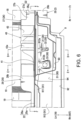
- FIG. 6 shows a cross sectional view taken along C-C in FIG. 1
- FIG. 7 shows a cross sectional view taken along D-D in FIG. 6
- FIG. 8 shows a cross sectional view taken along E-E in FIG. 6
- FIG. 9 shows an external perspective diagram of the gusset member 40 as viewed from an inside of the vehicle in the vehicle width direction
- FIG. 10 shows a cross sectional view taken along F-F in FIG. 6 .
- FIG. 1 illustration of a door outer panel 92 of the rear door 9 is omitted in FIG. 1 .
- the arrows Fr and Rr indicate the longitudinal direction, wherein the arrow Fr indicates a forward direction, and the arrow Rr indicates a rearward direction.
- the arrows Rh and Lh indicate the width direction
- the arrow Rh indicates a righthand (right) direction
- the arrow Lh indicates a lefthand (left) direction
- the arrow IN indicates a direction toward the inside of the vehicle in the vehicle width direction (i.e., inboard)
- the arrow OUT indicates a direction toward the outside of the vehicle in the vehicle width direction (i.e., outboard).
- the side body vehicle structure of the vehicle 1 includes one or more, particularly, a pair of left and right side sills 2 extending in the vehicle longitudinal direction at positions that are separated by a predetermined distance in the vehicle width direction, one or more, particularly, a pair of left and right rear side frames 3 extending from the rear end of the side sills 2 to a rear part of the vehicle, one or more, particularly, a pair of left and right roof side rails 4 extending in the vehicle longitudinal direction on the upper part of the vehicle above the side sills 2, and one or more, particularly, a pair of left and right rear pillars 5 extending from the rear end of the rear side frames 3 toward a lower rear part of the vehicle.
- the side body vehicle structure of the vehicle 1 includes one or more, particularly, a pair of left and right rear wheel houses 6 covering rear wheels (not shown) from the upper part of the vehicle, one or more, particularly, a pair of left and right rear side panels 7 forming side walls of the rear part of the vehicle together with the rear wheel houses 6, and one or more, particularly, a pair of left and right side pillars 8 joined to the rear side panels 7 in the vicinity of a front end on an outside in the vehicle width direction of each rear side panel 7 and also forming a closed section extending in the vehicle vertical direction with the rear side panels 7.
- the side body vehicle structure of vehicle 1 includes one or more, particularly, a pair of left and right front pillars extending toward the lower front part of the vehicle from the front end of the roof side rails 4, and one or more, particularly, a pair of left and right hinge pillars connecting the front end of the side sills 2 with the front end of the front pillars in the vehicle vertical direction.
- the side body vehicle structure of the vehicle 1 forms an opening surrounded by the side sills 2, the roof side rails 4, the side pillars 8, the front pillars, and the hinge pillars as a doorway S for passenger ingress and egress.
- this doorway S is covered freely in a manner that is openable and closable by side doors that include a rear door 9 provided on a vehicle rear side of the side body vehicle structure and a front door (not shown) provided on a front side of the vehicle relative to the rear door 9.
- an on-vehicle battery 11 for supplying power to a traveling motor and a battery tray 12, to which the on-vehicle battery 11 is mounted and fixed are particularly provided at a lower part of the vehicle on a floor panel 10, or below the floor panel 10, which forms a floor of the vehicle 1 and connects the left and right side sills 2.
- the on-vehicle battery 11 is particularly configured with a substantially rectangular shape in the bottom surface view, having a length in the vehicle longitudinal direction from a front end to a rear end of the floor panel 10 between the left and right side sills 2, and an outermost length in the vehicle width direction within a range from an approximate middle of the battery in a vehicle longitudinal direction to a rear portion of the battery in a vehicle longitudinal direction, within which range the battery outer edges are parallel and closer to each respective the side sill 2 than at locations on the battery 11 closer to a front part of the vehicle, where the battery outer edges are non-parallel and slightly angle towards the center of the vehicle in the vehicle width direction.
- a battery tray 12 particularly has an approximately polygonal shape in the bottom surface view with an area larger than that of the on-vehicle battery 11 and is formed in an approximate box shape with a portion thereof opened toward an upper part of the vehicle.
- the battery tray 12 is particularly connected to the left and right side sills 2 via one or more, particularly, a pair of left and right first connection brackets 13, one or more, particularly, a pair of left and right second connection brackets 14, and one or more, particularly, a pair of left and right third connection brackets 15.
- the left and right first connection brackets 13 connect the battery tray 12 with the side sills 2 (at an inner lower surface part 27d of an side sill inner member 26 described later) in the vehicle width direction at a position that is more toward a front part of the vehicle than the approximate center in the vehicle longitudinal direction of the side sills 2.
- the left and right second connection brackets 14 connect the battery tray 12 with the side sills 2 (at an inner lower surface part 27d of the side sill inner member 26 described later) in the vehicle width direction at a position that is at an approximate center in the vehicle longitudinal direction of the side sills 2.
- connection brackets 15 connect the battery tray 12 with the side sills 2 (at an inner side surface part 28c of the side sill inner member 26 described later) in the vehicle width direction via forth connection brackets 16 at a position of the vicinity of the rear end of the side sills 2.
- the side doors of this embodiment are particularly so-called opposite swing type side doors, in which a rear door 9 thereof is supported by the side pillar 8 on a rear side of the door via a door hinge 17 so as to be freely opened and closed and a front door thereof is supported on a front side of the door by a hinge pillar via a door hinge so as to be freely opened and closed.
- the rear door 9 may be configured to be openable and closable in a state of the front door opened.
- the rear door 9 of the side door particularly includes a door inner panel 91 that is a panel member covering the rear part of the doorway S, and a door outer panel 92 that is located to the outside in the vehicle width direction of the door inner panel 91 and also forms the external appearance design surface of the vehicle 1, and a center pillar 93 that is joined to the door inner panel 91.
- the door inner panel 91 is particularly formed in a shape in which a lower end of the front end edge thereof is located at approximately the same position in the vehicle longitudinal direction as a first floor cross member 18 provided at approximately the center in the vehicle longitudinal direction in the vehicle cabin, and also the upper edge, the rear edge, and the lower edge thereof are formed to overlap to the roof side rail 4, the side pillar 8, and the side sill 2 in the vehicle width direction, respectively.
- the first floor cross member 18 particularly connects the left and right side sills 2 in the vehicle width direction and also is formed in a shape forming a closed cross section extending in the vehicle width direction with the floor panel 10.
- the door inner panel 91 particularly has a door bottom part 912 provided so as to be extended toward the outside of the vehicle in the vehicle width direction from the lower end of a door side surface part 911 covering the doorway S.
- a door bottom part 912 is particularly provided at a position of a part of the vehicle lower than the upper end of the side sill 2 (at an upper end of a rear door facing part 22a in an upper flange portion 22 that will be described later) and also a part of the vehicle higher than the upper surface of the side sill 2 (at an upper surface part 25b of a side sill outer member 25 that will be described later).
- a reinforcement 94 reinforcing approximately the same range in the vehicle longitudinal direction as the center pillar 93 occupies, is joined to the upper surface of the door bottom part 912.
- a striker opening part 912a which is a notched opening through which a striker 30 provided on the side sill 2 can be inserted in the vehicle width direction
- a pin opening part 912b which is a notched opening through which a catcher pin 33 can be inserted in the vehicle width direction
- the center pillar 93 particularly has a cross sectional shape in a horizontal cross section along the vehicle width direction that is an approximately hat-shaped and protrudes toward the outside of the vehicle in the vehicle width direction, and forms a closed cross section extending in the vehicle vertical direction by being joined to a surface toward an outside of the vehicle in vehicle width direction at the door side surface part 911 of the door inner panel 91.
- hat shape is particularly used to refer to a shape having a central protrusion that resembles a crown of a hat, surrounded by a substantially flat surface resembling a brim of a hat.
- the lower end of the center pillar 93 is particularly joined to a part that extends from a lower part of the vehicle, from the edge of an outside in the vehicle width direction of the door bottom part 912, with the reinforcement 94 in between.
- the rear ends of the left and right side sills 2 are particularly joined to a front part of a lower end of a rear wheel house 6, a front part of a lower end of a rear side panel 7, and a lower end of the side pillar 8, and the front ends thereof are joined to the lower end of a hinge pillar (not shown).
- the side sills 2 are particularly formed to have a cross sectional shape in a vertical cross section along the vehicle width direction.
- the cross sectional shape of the sills 2 particularly includes a closed cross section part 21 that is a closed cross section of an approximately rectangular cross section, an upper flange portion 22 provided so as to extend upward or toward an upper part of the vehicle from an approximate center position in the vehicle width direction on the upper surface of the closed cross section part 21, and a lower flange part 23 provided so as to extend downward or toward a lower part of the vehicle from an approximate center position in the vehicle width direction on the lower surface of the closed cross section part 21.
- the upper flange portion 22 of the side sills 2 is formed integrally with the rear door facing part 22a, which is a part facing the rear door 9, and a front door facing part 22b, which is a part facing the front door, in this order from the vehicle rear part.
- the rear door facing part 22a of the upper flange portion 22 is formed in a shape having a length (i.e., height in FIG. 4 ) in the vehicle vertical direction longer than the length (i.e., height in FIG. 4 ) in the vehicle vertical direction of the front door facing part 22b, as seen in a side view.
- the rear door facing part 22a of the upper flange portion 22 is formed in a shape where the upper end thereof is located at a part of the vehicle that is higher than the upper end of the front door facing part 22b in a side view. Therefore, the upper end of the rear door facing part 22a is located above the upper end of the front door facing part 22b.
- each side sill 2 as shown in FIG. 6 which has a cross sectional shape in the vertical cross section along the vehicle width direction, is joined with the side sill outer member 25, which is approximately hat-shaped in cross section and protrudes toward an outside of the vehicle in the vehicle width direction, and further is joined with the side sill inner member 26, which is approximately hat-shaped in cross section and protrudes toward an inside of the vehicle in the vehicle width direction, and thereby forms a closed cross section extending in the vehicle longitudinal direction.
- the side sill outer member 25 is formed integrally by an outer upper flange portion 25a that forms the upper flange portion 22 with inner upper flange portion 27a of the side sill inner member 26, an outer upper surface part 25b provided to extend toward an outside of the vehicle in the vehicle width direction from the lower end of the outer upper flange portion 25a, an outer side surface part 25c provided to extend toward a lower part of the vehicle from the outer edge in the vehicle width direction of the outer upper surface part 25b, an outer lower surface part 25d provided to extend to the inside in the vehicle width direction from the lower end of the outer side surface part 25c, and an outer lower flange part 25e provided to extend toward a lower part of the vehicle lower from an inside edge in the vehicle width direction of the outer lower surface part 25d.
- the striker 30, with which the rear door 9 engages is particularly connected to the outer upper surface part 25b of the side sill outer member 25.
- the striker 30 is formed integrally by a striker base 31 connected to the outer upper surface part 25b of the side sills 2, a striker main body 32, with which a latch (not shown) provided on the rear door 9 engages, and a catcher pin 33 provided on a more rearward part of the vehicle than the striker main body 32.
- the striker base 31 is particularly formed in a shape in which two parts of an approximate hat-shape in a side view protrude toward an upper part of the vehicle in a side view and are juxtaposed in the vehicle longitudinal direction.
- the striker main body 32 is particularly attached on a vehicle front side and the catcher pin 33 is particularly attached on a vehicle rear side on the parts of the striker base 31 protruding toward an upper part of the vehicle.
- the striker base 31 is particularly connected to the outer upper surface part 25b of the side sill outer member 25 so that the striker main body 32 and the catcher pin 33 are located within the closed cross-section formed by the door inner panel 91 and the center pillar 93.
- the striker base 31 is particularly connected to the outer upper surface part 25b of the side sill outer member 25 so that the striker main body 32 and the catcher pin 33 are located at approximately the same position in the vehicle longitudinal direction as the lower end of the center pillar 93.
- the striker base 31 is particularly connected to the side sill outer member 25 in the vertical cross section along the vehicle width direction via a striker reinforcement 34 forming a closed cross section with the side sill outer member 25.
- the striker main body 32 is an approximately tunnel or door shape as viewed in a front view that protrudes toward an upper part of the vehicle, and is formed into a shape capable of engaging with the latch provided on the rear door 9.
- the catcher pin 33 is particularly integrally formed with an approximately cylindrical part extending toward the upper part of the vehicle from the striker base 31 and with an approximately disk-shaped part having a predetermined thickness in the vehicle vertical direction.
- the catcher pin 33 is particularly provided as a regulating member for regulating (i.e., limiting) a movement of the rear door 9 to the inside of the vehicle in the vehicle width direction.
- the side sill inner member 26 is particularly formed by an inner member front part 27 located toward a front part of the vehicle and an inner member rear part 28 located toward a rear part of the vehicle relative to the inner member front part 27 so as to divide the rear door facing part 22a of the upper flange portion 22 at a predetermined position in the vehicle longitudinal direction between the first floor cross member 18 and a second floor cross member 19 provided toward a rear part of the vehicle at a predetermined distance relative to the first floor cross member 18.
- the second floor cross member 19 particularly connects the left and right side sills 2 in the vehicle width direction and also is formed in a shape forming a closed cross section extending in the vehicle width direction with the floor panel 10.
- the inner member front part 27 is particularly formed integrally in the vertical cross section along the vehicle width direction by an inner upper flange portion 27a forming an upper flange portion 22 together with the side sill outer member 25, an inner upper surface part 27b provided to extend toward an inside of the vehicle in the vehicle width direction from the lower end of the inner upper flange portion 27a, an inner side surface part 27c provided to extend toward a lower part of the vehicle from an edge of the inside in the vehicle width direction on the inner upper surface part 27b, an inner lower surface part 27d provided to extend toward an outside of the vehicle in the vehicle width direction from the lower end of the inner side surface part 27c, and an inner lower flange portion 27e provided to extend toward a vehicle lower part from an outer edge in the vehicle width direction of the inner lower surface part 27d.
- the inner member rear part 28 is formed integrally in the vertical cross section along the vehicle width direction by an inner upper flange portion 28a forming an upper flange portion 22 together with the side sill outer member 25, an inner upper surface part 28b provided to extend to an inside of the vehicle in the vehicle width direction from the lower end of the inner upper flange portion 28a, an inner side surface part 28c provided to extend toward a lower part of the vehicle from an inside edge in the vehicle width direction of the inner upper surface part 28b, an inner lower surface part 28d provided to extend toward an outside of the vehicle in the vehicle width direction from the lower end of the inner side surface part 28c, and an inner lower flange portion 28e provided to extend toward the vehicle lower part from an edge of the outside in the vehicle width direction on the inner lower surface part 28d.
- the above-described inner member front part 27 and inner member rear part 28 are particularly formed to have a length in the vehicle longitudinal direction overlapping in the vehicle vertical direction and the vehicle width direction.
- the inner member front part 27 is formed in a shape having a length in the vehicle longitudinal direction where the rear end thereof is located at a more rearward part of the vehicle than the catcher pin 33, and the front end thereof is joined to the hinge pillar. Therefore, the inner member front part 27 extends rearward beyond the catcher pin 33 in the vehicle longitudinal direction.
- the inner member rear part 28 is particularly formed in a shape having a length in the vehicle longitudinal direction where the rear end thereof is located at a joined part of a front part lower end of the rear wheel house 6, a front part lower end of the rear side panel 7, and a lower end of the side pillar 8, and the front end thereof is located at approximately the same position in the vehicle longitudinal direction as the catcher pin 33.
- the vicinity of the rear end of the inner member front part 27 and the vicinity of the front end of the inner member rear part 28 are overlapped with each other in the vehicle vertical direction and the vehicle width direction with a gusset member 40 to be described later therebetween and are joined to each other via the gusset member 40.
- the inner upper flange portion 27a thereof is joined to the outer upper flange portion 25a of the side sill outer member 25 and the inner lower flange portion 27e thereof is joined to the outer lower flange portion 25e of the side sill outer member 25.
- the upper part of the inner upper flange portion 28a thereof is directly joined to the upper part of the inner upper flange portion 27a of the inner member front part 27, and also the lower part of the inner upper flange portion 28a thereof is joined to the lower part of the inner upper flange portion 27a of the inner member front part 27 with the gusset member 40 to be described later therebetween.
- the inner upper surface part 28b thereof is joined to the upper surface of the inner upper flange portion 27a of the inner member front part 27 with the gusset member 40 therebetween, and the upper part of the inner side surface part 28c thereof is joined to the upper part of the inner side surface part 27c of the inner member front part 27 with the gusset member 40 therebetween.
- the lower part of the inner side surface part 28c thereof is directly joined to the lower part of the inner side surface part 27c of the inner member front part 27, and the inner lower surface part 28d is directly joined to the lower surface of the inner lower surface part 27d of the inner member front part 27, and the inner lower flange portion 28e is directly joined to the inner lower flange portion 27e of the inner member front part 27.
- the side sill inner member 26 is joined to the rear door facing part 22a of the upper flange portion 22 of the side sill 2 at approximately the same position in the vehicle longitudinal direction as the lower part of the center pillar 93 and also a gusset member 40 is provided forming a closed section with the inner member front part 27.
- the gusset member 40 extends rearward beyond the catcher pin 33 in the vehicle longitudinal direction.
- the gusset member 40 is formed in a shape having a length in the vehicle longitudinal direction that extends more rearward on the vehicle than the catcher pin 33 from approximately the same position in the vehicle longitudinal direction as the front end of the part protruding toward an outside of the vehicle in the vehicle width direction of the center pillar 93. Therefore, as shown in FIG. 8 and FIG. 10 , the gusset member 40 is formed in a shape having a length in the vehicle longitudinal direction overlapping a vicinity of a rear end thereof with a vicinity of a rear end of the overlapped inner member front part 27 and a vicinity of the front end of the inner member rear part 28.
- the gusset member 40 is particularly formed integrally by a gusset upper surface part 43 having an upper joint part 41 joined to the inner upper flange portion 27a of the inner member front part 27, a lower joint part 42 joined to the inner side surface part 27c of the inner member front part 27, a bulged part 43a bulging toward an upper part of the vehicle between an upper side joint part 41 and a lower side joint part 42.
- the vicinity of the rear end of the upper side joint part 41 is formed in a shape intervening between the inner upper flange portion 27a of the inner member front part 27 overlapping in the vehicle width direction and the inner upper flange portion 28a of the inner member rear part 28.
- the vicinity of the rear end of the upper side joint part 41 is joined to the outer upper flange portion 25a of the side sill outer member 25 via the front part 27 in an intervening state between the inner upper flange portion 27a of the inner member front part 27 overlapped in the vehicle width direction and the inner upper flange portion 28a of the inner member rear part 28.
- the vicinity of the rear end of the lower side joint part 42 is formed in a shape that can be intervened (i.e., inserted) between an inner side surface part 27c of the inner member front part 27 overlapped in the vehicle width direction and an inner side surface part 28c of the inner member rear part 28.
- the vicinity of the rear end of the lower side joint part 42 is joined to the inner member front part 27 in an intervening state between the inner side surface part 27c of the inner member front part 27 overlapped in the vehicle width direction and the inner side surface part 28c of the inner member rear part 28.
- the gusset upper surface part 43 is joined to the inner member front part 27 in a state in which the vicinity of the front end thereof is joined to the inner upper surface part 27b of the inner member front part 27 and the vicinity of the rear end thereof is intervened between the inner upper surface part 27b of the inner member front part 27 overlapping in the vehicle vertical direction and the inner upper surface part 28b of the inner member rear part 28.
- the bulged part 43a of the gusset upper surface part 43 is formed so as to be a closed cross sectional shape that is approximately triangular in a front view with an inner upper flange portion 27a of the inner member front part 27 and an inner upper surface part 27b of the inner member front part 27 in the vertical cross section along the vehicle width direction.
- the bulged part 43a of the gusset upper surface part 43 is in an approximately circular arc shape in a side view that is curved so as to protrude toward an upper part of the vehicle, and is formed in a shape bulging toward the upper part of the vehicle so as to be formed between the upper part of the inner upper flange portion 27a of the inner member front part 27 and the upper end of the inner side surface part 27c of the inner member front part 27 in the vertical cross section along the vehicle width direction.
- the bulged part 43a is formed in a shape bulging toward the upper part of the vehicle so that the upper end thereof is located at approximately the same position in the vehicle longitudinal direction as the striker main body 32 of the striker 30.
- three beads which are protruding toward the upper part of the vehicle and also extended along the vehicle width direction, are particularly formed at predetermined intervals (i.e., separation distances) in the vehicle longitudinal direction in the bulged part 43a.
- a side body vehicle structure of a vehicle 1 has a pair of left and right side sills 2 extending in the vehicle longitudinal direction at a predetermined distance from each other in the vehicle width direction of the vehicle 1 and opposite swing type side doors which are formed on the vehicle upper part of the side sills 2 and cover freely openably and closably a doorway S for passenger ingress and egress.
- the side body vehicle structure of the vehicle 1 can suppress an intrusion of a rear door 9 into the vehicle cabin at the time of a side collision, since the side sills 2 have an outer upper flange portion 25a of the approximately hat-shaped side sill outer member 25 and the upper flange portion 22 formed the inner upper flange portions 27a and 28a of the approximately hat-shaped side sill inner member 26 in the vertical cross section along the vehicle width direction, the side door has a rear door 9 that covers a rear part of the doorway S, the upper flange portion 22 facing the rear door 9 in the vehicle width direction functions as a rear door facing part 22a, and the upper flange portion 22 of a more forward part of the vehicle than the rear door facing part 22a functions as a front door facing part 22b, the rear door facing part 22a is formed in a shape having a length in the vehicle vertical direction longer than a length in a vehicle vertical direction of the front door facing part 22b, and a gusset member 40 forming a closed cross section with the side
- the side body vehicle structure of the vehicle 1 can secure a large contact area between the rear door 9 and the side sill 2 as compared to the case where the rear door facing part 22a has approximately the same length in the vertical direction as the front door facing part 22b.
- the side body vehicle structure of the vehicle 1 can support the upper flange portion 22 from the inside of the vehicle in the vehicle width direction.
- the side body vehicle structure of the vehicle 1 can secure a large cross sectional area of a closed cross section formed by the side sill inner member 26 and the gusset member 40 in the vertical cross section along the vehicle width direction as compared to the case where the rear door facing part 22a has approximately the same length in the vertical direction as the front door facing part 22b.
- the side body vehicle structure of the vehicle 1 can support the rear door facing part 22a by the gusset member 40 and also can reinforce the part facing the rear door 9 of the side sill 2 by the gusset member 40.
- the side body vehicle structure of the vehicle 1 can suppress the collapsing deformation of the rear door facing part 22a toward the inside of the vehicle in the vehicle width direction and the deformation of the side sill 2 toward the inside of the vehicle in the vehicle width direction.
- the side body vehicle structure of the vehicle 1 can suppress an intrusion of the rear door 9 into the vehicle cabin at the time of a side collision.
- the side body vehicle structure of the vehicle 1 can suppress the deformation of the rear door 9 toward the inside of the vehicle in the vehicle width direction at the time of the side collision and can further suppress the intrusion of the rear door 9 into the vehicle cabin.
- the side body vehicle structure of the vehicle 1 can improve the rigidity of the rear door 9.
- the gusset member 40 is provided at approximately the same position in the vehicle longitudinal direction as the lower part of the center pillar 93, the side body vehicle structure of the vehicle 1 can stably transmit the side collision load at the time of the side collision to the side sill 2 via the center pillar 93 and the gusset member 40.
- the side body vehicle structure of the vehicle 1 can further suppress the deformation of the rear door 9 toward the inside of the vehicle in the vehicle width direction at the time of the side collision.
- the side body vehicle structure of the vehicle 1 can suppress the deformation of the rear door 9 toward the inside of the vehicle in the vehicle width direction at the time of the side collision and can further suppress the intrusion of the rear door 9 into the vehicle cabin.
- the striker 30, which engages with a latch provided on the rear door 9 is provided on the upper surface of the side sill outer member 25 and the gusset member 40 is provided on approximately the same position as the striker 30 in the vehicle longitudinal direction, when the compression load toward the inside in the vehicle width direction acts on the striker 30 via the rear door 9, the side body vehicle structure of the vehicle 1 can suppress the displacement of the striker 30 toward the inside of the vehicle in the vehicle width direction by a closed cross section formed by the side sill inner member 26 and the gusset member 40. Therefore, the side body vehicle structure of the vehicle 1 can more surely suppress the intrusion of the rear door 9 into the vehicle cabin at the time of the side collision.
- the striker 30 is configured with the striker base 31 connected to the upper surface of the side sill outer member 25 and the striker main body 32 engaged with the latch of the rear door 9, and the catcher pin 33 for restricting the movement of the rear door 9 to the inside of the vehicle in the vehicle width direction is provided on the upper surface of the side sill outer member 25 and formed integrally to the striker base 31 while being adjacent to the striker main body 32, the side body vehicle structure of the vehicle 1 can improve the assemblability of the striker main body 32 to the side sill outer member 25 and the catcher pin 33, and also can reduce the assembly time as compared with the case where the striker main body 32 and the catcher pin 33 are separately configured.
- the side body vehicle structure of the vehicle 1 can suppress the deformation of the catcher pin 33 toward the inside of the vehicle in the vehicle width direction by a closed cross section formed by the side sill inner member 26 and the gusset member 40. Therefore, the side body vehicle structure of the vehicle 1 can more surely suppress the intrusion of the rear door 9 into the vehicle cabin at the time of the side collision.
- the side sill inner member 26 is configured by the inner member front part 27 on which the gusset member 40 is provided and the inner member rear part 28 connected to a rear end of the inner member front part 27, and the gusset member 40 is formed in a shape overlapping at a boundary between the inner member front part 27 and the inner member rear part 28, even when the side sill inner member 26 is divided into the inner member front part 27 and the inner member rear part 28, the side body vehicle structure of the vehicle 1 can secure rigidity at the boundary between the inner member front part and the inner member rear part by the gusset member 40.
- the side body vehicle structure of the vehicle 1 can prevent the boundary between the inner member front part 27 and the inner member rear part 28 from becoming the weakest part against the compression load from the outside in the vehicle width direction.
- the side body vehicle structure of the vehicle 1 can stably suppress the intrusion of the rear door 9 into the vehicle cabin at the time of the side collision.
- the side body vehicle structure of the vehicle 1 can prevent the compression load toward the inside in the vehicle width direction from directly acting on the on-vehicle battery 11 by the side sills 2, of which the deformation thereof toward the inside of the vehicle in the vehicle width direction is suppressed by the gusset member 40. Therefore, the side body vehicle structure of the vehicle 1, for example, can provide more (or larger) on-vehicle batteries 11 for supplying electric power to a drive motor on the vehicle lower part of the floor panel 10.
- a part raised to the vehicle upper part of the side sill outer member of the present invention corresponds to the outer upper flange portion 25a of the side sill outer member 25 of the embodiment
- a part raised to the vehicle upper part of the side sill inner member corresponds to the inner upper flange portion 27a and the inner upper flange portion 28a of the side sill inner member 26
- the flange portion facing the rear door corresponds to the rear door facing part 22a
- the present invention is not limited to only the configuration of the above described embodiment, and many other embodiments are possible.
- the side body vehicle structure is provided with the gusset member 40 in a shape bulged toward an upper part of the vehicle and with the side sill inner member 26, the present invention is not limited thereto, and as long as a gusset member forms a closed cross section with the side sill inner member 26, it may have an appropriate shape.
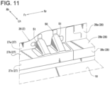
- the gusset member 50 may be provided with two protruded parts 51 having an approximately triangular shape in a front view protruding toward an upper part of the vehicle, at a predetermined interval from each other in the vehicle longitudinal direction.
- the gusset member 50 having such a configuration, since the inner upper flange portion 27a and the inner upper surface part 27b of the inner member front part 27 and the protruded part 51 of the gusset member 50 can form a closed cross section extending in the vehicle width direction, the same effects as those of the above described embodiment can be obtained.
- the embodiments are not limited thereto, and it will be appreciated that a configuration might be adopted in which the inner member front part 27, the inner member rear part 28, and the gusset member 40 are integrally joined in a state that the rear end of the gusset member 40 is further overlapped to the upper or lower surface of the overlapped part of the rear end of the inner member front part 27 and the front end of the inner member rear part 28.
Landscapes
- Engineering & Computer Science (AREA)
- Mechanical Engineering (AREA)
- Chemical & Material Sciences (AREA)
- Combustion & Propulsion (AREA)
- Transportation (AREA)
- Body Structure For Vehicles (AREA)
- Arrangement Or Mounting Of Propulsion Units For Vehicles (AREA)
Claims (15)
- Seitliche Fahrzeugkarosseriestruktur für ein Fahrzeug (1), aufweisend:einen Seitenschweller (2), der sich in einer Fahrzeuglängsrichtung erstreckt; undSeitentüren, die oberhalb des Seitenschwellers (2) positioniert und konfiguriert sind, eine Öffnung oder einen Türeingang (S) für den Ein- und Ausstieg von Passagieren frei öffenbar und schließbar abzudecken,wobei die Seitentüren eine hintere Tür (9) aufweisen, die konfiguriert ist, einen hinteren Teil der Öffnung oder des Türeingangs (S) abzudecken,wobei der Seitenschweller (2) einen oberen Flanschabschnitt (22) aufweist, der in einem vertikalen Querschnitt entlang der Fahrzeugbreitenrichtung einen Abschnitt eines Seitenschweller-Außenelements (25), der nach oben ragt, und einen Abschnitt eines Seitenschweller-Innenelements (26), der nach oben ragt, aufweist,wobei der obere Flanschabschnitt (22) einen der hinteren Tür zugewandten Flanschabschnitt (22a) aufweist, der konfiguriert ist, der hinteren Tür (9) in der Fahrzeugbreitenrichtung zugewandt zu sein, und wobei ein der vorderen Tür zugewandter Flanschabschnitt (22b) vor dem der hinteren Tür zugewandten Flanschabschnitt (22a) liegt,wobei der der hinteren Tür zugewandte Flanschabschnitt (22a) in einer Form ausgebildet ist, die eine Länge in der Fahrzeugvertikalrichtung aufweist, die länger ist als eine Länge des der vorderen Tür zugewandten Flanschabschnitts (22b) in der Fahrzeugvertikalrichtung, undwobei ein Knotenelement (40) bereitgestellt ist, das in einem vertikalen Querschnitt entlang der Fahrzeugbreitenrichtung ein oberes Ende aufweist, das mit dem der hinteren Tür zugewandten Flanschabschnitt (22a) verbunden ist, und konfiguriert ist, mit dem Seitenschweller-Innenelement (26) einen geschlossenen Querschnitt zu bilden,dadurch gekennzeichnet, dassdas Knotenelement (40) mit einem inneren oberen Flanschabschnitt (27a) verbunden ist, der den oberen Flanschabschnitt (22) bildet,das Knotenelement (40) mit einem inneren oberen Flächenteil (27b) des Seitenschweller-Innenelements (26) verbunden ist,das Knotenelement (40) so ausgebildet ist, dass es eine geschlossene Querschnittsform mit dem inneren oberen Flanschabschnitt (27a) und dem inneren oberen Flächenteil (27b) ist,das Knotenelement (40) durch einen oberen Knotenflächenteil (43) einstückig ausgebildet ist, der einen oberen Verbindungsteil (41), der mit dem inneren oberen Flanschabschnitt (27a) verbunden ist, einen unteren Verbindungsteil (42), der mit einem inneren Seitenflächenteil (27c) verbunden ist, der sich von einem Rand eines Inneren in Richtung eines unteren Teils des Fahrzeugs in der Fahrzeugbreitenrichtung auf dem inneren oberen Flächenteil (27b) erstreckt, einen gewölbten Teil (43a), der sich in Richtung eines oberen Teils des Fahrzeugs (1) zwischen dem oberen Verbindungsteil (41) und dem unteren Verbindungsteil (42) wölbt, aufweist, undder gewölbte Teil (43a) des oberen Knotenflächenteils (43) so ausgebildet ist, dass er eine geschlossene Querschnittsform ist, die in einer Vorderansicht mit dem inneren oberen Flanschabschnitt (27a) und dem inneren oberen Flächenteil (27b) in dem vertikalen Querschnitt entlang der Fahrzeugbreitenrichtung annähernd dreieckig ist.
- Seitliche Fahrzeugkarosseriestruktur eines Fahrzeugs (1) nach Anspruch 1, wobeidie hintere Tür (9) eine Mittelsäule (93) aufweist, die sich in der Fahrzeugvertikalrichtung erstreckt, unddas Knotenelement (40) an im Wesentlichen einer selben Position in der Fahrzeuglängsrichtung wie ein unterer Teil der Mittelsäule (93) bereitgestellt ist.
- Seitliche Fahrzeugkarosseriestruktur eines Fahrzeugs (1) nach Anspruch 1 oder 2, ferner aufweisend:einen Schließer (30) auf einer oberen Fläche des Seitenschweller-Außenelements (25),wobei der Schließer (30) konfiguriert ist, mit einem an der hinteren Tür (9) bereitgestellten Verschluss in Eingriff zu gelangen, undwobei das Knotenelement (40) an im Wesentlichen einer selben Position wie der Schließer (30) in der Fahrzeuglängsrichtung bereitgestellt ist.
- Seitliche Fahrzeugkarosseriestruktur eines Fahrzeugs (1) nach Anspruch 3, ferner aufweisend:einen Fangbolzen (33), der konfiguriert ist, die Bewegung der hinteren Tür (9) in Richtung eines Inneren des Fahrzeugs (1) in der Fahrzeugbreitenrichtung einzuschränken, und auf der oberen Fläche des Seitenschweller-Außenelements (25) bereitgestellt ist,wobei der Schließer (30) eine Schließerbasis (31), die mit der oberen Fläche des Seitenschweller-Außenelements (25) verbunden ist, und einen Schließerhauptkörper (32) aufweist,wobei der Verschluss der hinteren Tür (9) konfiguriert ist, mit dem Schließerhauptkörper (32) in Eingriff zu gelangen.
- Seitliche Fahrzeugkarosseriestruktur eines Fahrzeugs (1) nach Anspruch 4, wobei der Fangbolzen (33) zu dem Schließerhauptkörper (32) benachbart ist und mit der Schließerbasis (31) einstückig ausgebildet ist.
- Seitliche Fahrzeugkarosseriestruktur eines Fahrzeugs (1) nach einem der vorhergehenden Ansprüche,
wobei das Seitenschweller-Innenelement (26) einen Innenelement-Vorderteil (27), an dem das Knotenelement (40) bereitgestellt ist, und einen Innenelement-Hinterteil (28) aufweist, der mit einem hinteren Ende des Innenelement-Vorderteils (27) verbunden ist. - Seitliche Fahrzeugkarosseriestruktur eines Fahrzeugs (1) nach Anspruch 6, wobei das Knotenelement (40) in einer überschneidenden Form an einer Grenze zwischen dem Innenelement-Vorderteil (27) und dem Innenelement-Hinterteil (28) ausgebildet ist.
- Seitliche Fahrzeugkarosseriestruktur eines Fahrzeugs (1) nach einem der vorhergehenden Ansprüche, ferner aufweisend ein Scharnier (17), das konfiguriert ist, eine Hinterseite der hinteren Tür (9) zu tragen.
- Seitliche Fahrzeugkarosseriestruktur eines Fahrzeugs (1) nach einem der vorhergehenden Ansprüche, wobeidie Seitentüren eine vordere Tür umfassen, die konfiguriert ist, einen Vorderteil der Öffnung oder des Türeingangs (S) abzudecken, unddie seitliche Fahrzeugkarosseriestruktur ferner ein Scharnier aufweist, das konfiguriert ist, eine Vorderseite der vorderen Tür zu tragen.
- Seitliche Fahrzeugkarosseriestruktur eines Fahrzeugs (1) nach einem der vorhergehenden Ansprüche, wobei in dem vertikalen Querschnitt entlang der Fahrzeugbreitenrichtung das Seitenschweller-Außenelement (25) einen im Wesentlichen hutförmigen Querschnitt aufweist und das Seitenschweller-Innenelement (26) einen im Wesentlichen hutförmigen Querschnitt aufweist.
- Seitliche Fahrzeugkarosseriestruktur eines Fahrzeugs (1) nach einem der vorhergehenden Ansprüche, ferner aufweisend einen weiteren Seitenschweller (2), der sich in der Fahrzeuglängsrichtung erstreckt,
wobei die Seitenschweller (2) um einen vorbestimmten Abstand in einer Fahrzeugbreitenrichtung des Fahrzeugs (1) getrennt sind. - Seitliche Fahrzeugkarosseriestruktur eines Fahrzeugs (1) nach Anspruch 11, ferner aufweisend eine Bodenplatte (10), die zwischen den Seitenschwellern (2) bereitgestellt und konfiguriert ist, eine Bodenfläche des Fahrzeugs (1) zu bilden.
- Fahrzeug (1), aufweisend eine seitliche Karosseriestruktur nach einem der vorhergehenden Ansprüche.
- Fahrzeug (1) nach Anspruch 13 und aufweisend die seitliche Karosseriestruktur nach Anspruch 12, ferner aufweisend eine Batterie (11), die an dem unteren Fahrzeugteil der Bodenplatte (10) oder unterhalb der Bodenplatte bereitgestellt ist.
- Fahrzeug (1) nach Anspruch 14, wobei die Batterie (11) so bereitgestellt ist, dass sie dem Seitenschweller-Innenelement (26) an annähernd einer selben Position wie das Knotenelement (40) in der Fahrzeuglängsrichtung am nächsten liegt.
Applications Claiming Priority (1)
| Application Number | Priority Date | Filing Date | Title |
|---|---|---|---|
| JP2018093166A JP7070068B2 (ja) | 2018-05-14 | 2018-05-14 | 車両の側部車体構造 |
Publications (2)
| Publication Number | Publication Date |
|---|---|
| EP3569481A1 EP3569481A1 (de) | 2019-11-20 |
| EP3569481B1 true EP3569481B1 (de) | 2023-07-12 |
Family
ID=66476457
Family Applications (1)
| Application Number | Title | Priority Date | Filing Date |
|---|---|---|---|
| EP19173444.1A Active EP3569481B1 (de) | 2018-05-14 | 2019-05-09 | Seitliche fahrzeugkarosseriestruktur und fahrzeug |
Country Status (3)
| Country | Link |
|---|---|
| US (1) | US11014613B2 (de) |
| EP (1) | EP3569481B1 (de) |
| JP (1) | JP7070068B2 (de) |
Families Citing this family (7)
| Publication number | Priority date | Publication date | Assignee | Title |
|---|---|---|---|---|
| JP7070068B2 (ja) * | 2018-05-14 | 2022-05-18 | マツダ株式会社 | 車両の側部車体構造 |
| JP7159638B2 (ja) * | 2018-06-25 | 2022-10-25 | マツダ株式会社 | 車両のドア構造 |
| JP7052715B2 (ja) * | 2018-12-28 | 2022-04-12 | トヨタ自動車株式会社 | 車両下部構造 |
| JP6807969B2 (ja) * | 2019-02-20 | 2021-01-06 | 本田技研工業株式会社 | 車両後部構造 |
| KR102644571B1 (ko) * | 2019-05-13 | 2024-03-06 | 현대자동차주식회사 | 차체 보강 장치 |
| JP7494749B2 (ja) * | 2021-02-02 | 2024-06-04 | トヨタ自動車株式会社 | 車載ドアのラッチ構造および車両 |
| KR20230013856A (ko) * | 2021-07-20 | 2023-01-27 | 현대자동차주식회사 | 차체 구조 |
Citations (1)
| Publication number | Priority date | Publication date | Assignee | Title |
|---|---|---|---|---|
| DE3103580A1 (de) * | 1980-02-04 | 1982-01-07 | The Budd Co., 48084 Troy, Mich. | Verstaerkungseinrichtung fuer eine tuer in einem kraftfahrzeug |
Family Cites Families (38)
| Publication number | Priority date | Publication date | Assignee | Title |
|---|---|---|---|---|
| JPH05155358A (ja) * | 1991-12-06 | 1993-06-22 | Mazda Motor Corp | 自動車の側部車体構造 |
| JP3335781B2 (ja) * | 1994-08-31 | 2002-10-21 | 富士重工業株式会社 | 車両のセンタピラー部全周閉断面構造 |
| US6305737B1 (en) | 2000-08-02 | 2001-10-23 | Asc Incorporated | Automotive vehicle door system |
| JP4715039B2 (ja) * | 2001-06-07 | 2011-07-06 | マツダ株式会社 | 車両の側部車体構造 |
| DE60223111T2 (de) * | 2001-07-04 | 2008-08-07 | Mazda Motor Corp. | Türstruktur für Fahrzeuge |
| JP4706139B2 (ja) * | 2001-07-18 | 2011-06-22 | マツダ株式会社 | 車両のドア構造 |
| JP2003252057A (ja) | 2002-02-27 | 2003-09-09 | Mazda Motor Corp | 車両のドア構造 |
| JP4106969B2 (ja) | 2002-05-29 | 2008-06-25 | マツダ株式会社 | 車両の車体構造 |
| US7950719B2 (en) * | 2007-09-14 | 2011-05-31 | Ford Global Technologies, Llc | Vehicle dual hinge rear door articulating and sliding system |
| DE102008005490B4 (de) | 2008-01-22 | 2017-03-23 | Bayerische Motoren Werke Aktiengesellschaft | Kfz mit einer vorderen u. einer hinteren Seitentür zum Verschließen einer seitlichen durchgehenden Türausschnittsöffnung |
| US7819465B2 (en) * | 2008-12-22 | 2010-10-26 | Ford Global Technologies, Llc | Transferable B-pillar for facilitating ingress/egress |
| CN102001362B (zh) * | 2009-08-27 | 2013-01-02 | 本田技研工业株式会社 | 车身构造 |
| US8607505B2 (en) * | 2010-07-27 | 2013-12-17 | GM Global Technology Operations LLC | Sealing assembly for a vehicle |
| JP5790365B2 (ja) * | 2011-09-20 | 2015-10-07 | トヨタ自動車株式会社 | 車両用バッテリ搭載構造 |
| KR101327738B1 (ko) * | 2012-10-11 | 2013-11-11 | 기아자동차주식회사 | 차량 도어의 후킹 구조 |
| JP5999437B2 (ja) * | 2013-03-29 | 2016-09-28 | 三井金属アクト株式会社 | 車両用ドアのストライカ装置 |
| JP2015123811A (ja) * | 2013-12-25 | 2015-07-06 | トヨタ自動車株式会社 | 車両骨格構造 |
| US9862309B2 (en) * | 2015-03-03 | 2018-01-09 | Nissan North America, Inc. | Vehicle sill illumination assembly |
| JP6319215B2 (ja) * | 2015-07-17 | 2018-05-09 | トヨタ自動車株式会社 | 車両骨格構造 |
| DE102015214085A1 (de) | 2015-07-24 | 2017-01-26 | Bayerische Motoren Werke Aktiengesellschaft | Türsystem für einen Kraftwagen sowie Verfahren zum Betreiben eines solchen Türsystems |
| DE102015214086B4 (de) * | 2015-07-24 | 2023-07-27 | Bayerische Motoren Werke Aktiengesellschaft | Türsystem für einen wenigstens zwei Sitzreihen umfassenden Personenkraftwagen |
| JP6284041B2 (ja) * | 2015-10-21 | 2018-02-28 | マツダ株式会社 | 車両のバッテリ搭載構造 |
| JP6211107B2 (ja) * | 2016-01-14 | 2017-10-11 | 本田技研工業株式会社 | 車体下部構造 |
| US9802651B2 (en) * | 2016-02-16 | 2017-10-31 | Nissan North America, Inc. | Vehicle body structure |
| US9701182B1 (en) * | 2016-02-24 | 2017-07-11 | Toyota Motor Engineering & Manufacturing North America, Inc. | Door reinforcement beam catch projections for vehicle side structures |
| FR3049260B1 (fr) | 2016-03-25 | 2018-11-16 | Renault S.A.S | Ensemble lateral avec ouverture de portes pour vehicule automobile, et procede d'assemblage associe. |
| JP6512162B2 (ja) * | 2016-04-21 | 2019-05-15 | トヨタ自動車株式会社 | 車両のバッテリ搭載構造 |
| JP6447600B2 (ja) * | 2016-09-29 | 2019-01-09 | トヨタ自動車株式会社 | 車両側部構造 |
| JP6523355B2 (ja) * | 2017-02-17 | 2019-05-29 | 本田技研工業株式会社 | 車体の下部構造 |
| US10596923B2 (en) * | 2017-03-06 | 2020-03-24 | Ford Global Technologies, Llc | Door mounted vehicle seat |
| US10407964B2 (en) * | 2017-04-19 | 2019-09-10 | Nissan North America, Inc. | Door striker assembly |
| US10886513B2 (en) * | 2017-05-16 | 2021-01-05 | Shape Corp. | Vehicle battery tray having tub-based integration |
| JP6647248B2 (ja) * | 2017-07-05 | 2020-02-14 | 本田技研工業株式会社 | 車体構造 |
| JP7070068B2 (ja) * | 2018-05-14 | 2022-05-18 | マツダ株式会社 | 車両の側部車体構造 |
| JP6628446B2 (ja) * | 2018-05-25 | 2020-01-08 | 本田技研工業株式会社 | 車体下部構造 |
| JP7159638B2 (ja) * | 2018-06-25 | 2022-10-25 | マツダ株式会社 | 車両のドア構造 |
| JP7234516B2 (ja) * | 2018-06-25 | 2023-03-08 | マツダ株式会社 | 車両の側部構造 |
| US11091016B2 (en) * | 2019-03-06 | 2021-08-17 | Mazda Motor Corporation | Lower vehicle-body structure of vehicle |
-
2018
- 2018-05-14 JP JP2018093166A patent/JP7070068B2/ja active Active
-
2019
- 2019-05-01 US US16/400,997 patent/US11014613B2/en active Active
- 2019-05-09 EP EP19173444.1A patent/EP3569481B1/de active Active
Patent Citations (1)
| Publication number | Priority date | Publication date | Assignee | Title |
|---|---|---|---|---|
| DE3103580A1 (de) * | 1980-02-04 | 1982-01-07 | The Budd Co., 48084 Troy, Mich. | Verstaerkungseinrichtung fuer eine tuer in einem kraftfahrzeug |
Also Published As
| Publication number | Publication date |
|---|---|
| JP2019199116A (ja) | 2019-11-21 |
| US20190344830A1 (en) | 2019-11-14 |
| EP3569481A1 (de) | 2019-11-20 |
| JP7070068B2 (ja) | 2022-05-18 |
| US11014613B2 (en) | 2021-05-25 |
Similar Documents
| Publication | Publication Date | Title |
|---|---|---|
| EP3569481B1 (de) | Seitliche fahrzeugkarosseriestruktur und fahrzeug | |
| US11192586B2 (en) | Lower vehicle-body structure of vehicle | |
| JP4385582B2 (ja) | 車両のサイドドア構造 | |
| EP3566931B1 (de) | Fahrzeugkarosseriestruktur und fahrzeug | |
| CN110228532B (zh) | 车辆的车体构造 | |
| CN109305225B (zh) | 车辆的侧部车身结构 | |
| CN110228533B (zh) | 车辆的车体构造 | |
| CN111591350B (zh) | 车辆的后部车身结构 | |
| JP5170188B2 (ja) | スライドドア車の下部車体構造 | |
| CN103958327B (zh) | 车体侧部结构 | |
| US20220135140A1 (en) | Body structure for vehicle | |
| JP2019196104A (ja) | 車両の側部車体構造 | |
| JP4857976B2 (ja) | 車両フロア構造 | |
| US11186323B2 (en) | Vehicle rear structure with reinforced back frame | |
| JP4720327B2 (ja) | スライドドア車の下部車体構造 | |
| JP4356412B2 (ja) | 車両の車体構造 | |
| US11142252B2 (en) | Upper vehicle-body structure | |
| JP7147395B2 (ja) | 車両の後部車体構造 | |
| JP4715039B2 (ja) | 車両の側部車体構造 | |
| JP2003095141A (ja) | 車両の下部車体構造 | |
| US12202546B2 (en) | Vehicle rear structure | |
| JP4120202B2 (ja) | 車両の下部車体構造 | |
| JP4288920B2 (ja) | 車両のサイドドア構造 | |
| US11420682B2 (en) | Vehicle-body structure of vehicle | |
| JP7552369B2 (ja) | 車両用ドア |
Legal Events
| Date | Code | Title | Description |
|---|---|---|---|
| PUAI | Public reference made under article 153(3) epc to a published international application that has entered the european phase |
Free format text: ORIGINAL CODE: 0009012 |
|
| STAA | Information on the status of an ep patent application or granted ep patent |
Free format text: STATUS: THE APPLICATION HAS BEEN PUBLISHED |
|
| AK | Designated contracting states |
Kind code of ref document: A1 Designated state(s): AL AT BE BG CH CY CZ DE DK EE ES FI FR GB GR HR HU IE IS IT LI LT LU LV MC MK MT NL NO PL PT RO RS SE SI SK SM TR |
|
| AX | Request for extension of the european patent |
Extension state: BA ME |
|
| STAA | Information on the status of an ep patent application or granted ep patent |
Free format text: STATUS: REQUEST FOR EXAMINATION WAS MADE |
|
| 17P | Request for examination filed |
Effective date: 20200518 |
|
| RBV | Designated contracting states (corrected) |
Designated state(s): AL AT BE BG CH CY CZ DE DK EE ES FI FR GB GR HR HU IE IS IT LI LT LU LV MC MK MT NL NO PL PT RO RS SE SI SK SM TR |
|
| STAA | Information on the status of an ep patent application or granted ep patent |
Free format text: STATUS: EXAMINATION IS IN PROGRESS |
|
| 17Q | First examination report despatched |
Effective date: 20210621 |
|
| GRAP | Despatch of communication of intention to grant a patent |
Free format text: ORIGINAL CODE: EPIDOSNIGR1 |
|
| STAA | Information on the status of an ep patent application or granted ep patent |
Free format text: STATUS: GRANT OF PATENT IS INTENDED |
|
| INTG | Intention to grant announced |
Effective date: 20230405 |
|
| GRAS | Grant fee paid |
Free format text: ORIGINAL CODE: EPIDOSNIGR3 |
|
| GRAA | (expected) grant |
Free format text: ORIGINAL CODE: 0009210 |
|
| STAA | Information on the status of an ep patent application or granted ep patent |
Free format text: STATUS: THE PATENT HAS BEEN GRANTED |
|
| AK | Designated contracting states |
Kind code of ref document: B1 Designated state(s): AL AT BE BG CH CY CZ DE DK EE ES FI FR GB GR HR HU IE IS IT LI LT LU LV MC MK MT NL NO PL PT RO RS SE SI SK SM TR |
|
| REG | Reference to a national code |
Ref country code: CH Ref legal event code: EP |
|
| REG | Reference to a national code |
Ref country code: IE Ref legal event code: FG4D |
|
| REG | Reference to a national code |
Ref country code: DE Ref legal event code: R096 Ref document number: 602019032415 Country of ref document: DE |
|
| REG | Reference to a national code |
Ref country code: LT Ref legal event code: MG9D |
|
| REG | Reference to a national code |
Ref country code: NL Ref legal event code: MP Effective date: 20230712 |
|
| REG | Reference to a national code |
Ref country code: AT Ref legal event code: MK05 Ref document number: 1586861 Country of ref document: AT Kind code of ref document: T Effective date: 20230712 |
|
| PG25 | Lapsed in a contracting state [announced via postgrant information from national office to epo] |
Ref country code: NL Free format text: LAPSE BECAUSE OF FAILURE TO SUBMIT A TRANSLATION OF THE DESCRIPTION OR TO PAY THE FEE WITHIN THE PRESCRIBED TIME-LIMIT Effective date: 20230712 |
|
| PG25 | Lapsed in a contracting state [announced via postgrant information from national office to epo] |
Ref country code: GR Free format text: LAPSE BECAUSE OF FAILURE TO SUBMIT A TRANSLATION OF THE DESCRIPTION OR TO PAY THE FEE WITHIN THE PRESCRIBED TIME-LIMIT Effective date: 20231013 |
|
| PG25 | Lapsed in a contracting state [announced via postgrant information from national office to epo] |
Ref country code: ES Free format text: LAPSE BECAUSE OF FAILURE TO SUBMIT A TRANSLATION OF THE DESCRIPTION OR TO PAY THE FEE WITHIN THE PRESCRIBED TIME-LIMIT Effective date: 20230712 |
|
| PG25 | Lapsed in a contracting state [announced via postgrant information from national office to epo] |
Ref country code: IS Free format text: LAPSE BECAUSE OF FAILURE TO SUBMIT A TRANSLATION OF THE DESCRIPTION OR TO PAY THE FEE WITHIN THE PRESCRIBED TIME-LIMIT Effective date: 20231112 |
|
| PG25 | Lapsed in a contracting state [announced via postgrant information from national office to epo] |
Ref country code: SE Free format text: LAPSE BECAUSE OF FAILURE TO SUBMIT A TRANSLATION OF THE DESCRIPTION OR TO PAY THE FEE WITHIN THE PRESCRIBED TIME-LIMIT Effective date: 20230712 Ref country code: RS Free format text: LAPSE BECAUSE OF FAILURE TO SUBMIT A TRANSLATION OF THE DESCRIPTION OR TO PAY THE FEE WITHIN THE PRESCRIBED TIME-LIMIT Effective date: 20230712 Ref country code: PT Free format text: LAPSE BECAUSE OF FAILURE TO SUBMIT A TRANSLATION OF THE DESCRIPTION OR TO PAY THE FEE WITHIN THE PRESCRIBED TIME-LIMIT Effective date: 20231113 Ref country code: NO Free format text: LAPSE BECAUSE OF FAILURE TO SUBMIT A TRANSLATION OF THE DESCRIPTION OR TO PAY THE FEE WITHIN THE PRESCRIBED TIME-LIMIT Effective date: 20231012 Ref country code: LV Free format text: LAPSE BECAUSE OF FAILURE TO SUBMIT A TRANSLATION OF THE DESCRIPTION OR TO PAY THE FEE WITHIN THE PRESCRIBED TIME-LIMIT Effective date: 20230712 Ref country code: LT Free format text: LAPSE BECAUSE OF FAILURE TO SUBMIT A TRANSLATION OF THE DESCRIPTION OR TO PAY THE FEE WITHIN THE PRESCRIBED TIME-LIMIT Effective date: 20230712 Ref country code: IS Free format text: LAPSE BECAUSE OF FAILURE TO SUBMIT A TRANSLATION OF THE DESCRIPTION OR TO PAY THE FEE WITHIN THE PRESCRIBED TIME-LIMIT Effective date: 20231112 Ref country code: HR Free format text: LAPSE BECAUSE OF FAILURE TO SUBMIT A TRANSLATION OF THE DESCRIPTION OR TO PAY THE FEE WITHIN THE PRESCRIBED TIME-LIMIT Effective date: 20230712 Ref country code: GR Free format text: LAPSE BECAUSE OF FAILURE TO SUBMIT A TRANSLATION OF THE DESCRIPTION OR TO PAY THE FEE WITHIN THE PRESCRIBED TIME-LIMIT Effective date: 20231013 Ref country code: FI Free format text: LAPSE BECAUSE OF FAILURE TO SUBMIT A TRANSLATION OF THE DESCRIPTION OR TO PAY THE FEE WITHIN THE PRESCRIBED TIME-LIMIT Effective date: 20230712 Ref country code: ES Free format text: LAPSE BECAUSE OF FAILURE TO SUBMIT A TRANSLATION OF THE DESCRIPTION OR TO PAY THE FEE WITHIN THE PRESCRIBED TIME-LIMIT Effective date: 20230712 Ref country code: AT Free format text: LAPSE BECAUSE OF FAILURE TO SUBMIT A TRANSLATION OF THE DESCRIPTION OR TO PAY THE FEE WITHIN THE PRESCRIBED TIME-LIMIT Effective date: 20230712 |
|
| PG25 | Lapsed in a contracting state [announced via postgrant information from national office to epo] |
Ref country code: PL Free format text: LAPSE BECAUSE OF FAILURE TO SUBMIT A TRANSLATION OF THE DESCRIPTION OR TO PAY THE FEE WITHIN THE PRESCRIBED TIME-LIMIT Effective date: 20230712 |
|
| REG | Reference to a national code |
Ref country code: DE Ref legal event code: R097 Ref document number: 602019032415 Country of ref document: DE |
|
| PG25 | Lapsed in a contracting state [announced via postgrant information from national office to epo] |
Ref country code: SM Free format text: LAPSE BECAUSE OF FAILURE TO SUBMIT A TRANSLATION OF THE DESCRIPTION OR TO PAY THE FEE WITHIN THE PRESCRIBED TIME-LIMIT Effective date: 20230712 Ref country code: RO Free format text: LAPSE BECAUSE OF FAILURE TO SUBMIT A TRANSLATION OF THE DESCRIPTION OR TO PAY THE FEE WITHIN THE PRESCRIBED TIME-LIMIT Effective date: 20230712 Ref country code: EE Free format text: LAPSE BECAUSE OF FAILURE TO SUBMIT A TRANSLATION OF THE DESCRIPTION OR TO PAY THE FEE WITHIN THE PRESCRIBED TIME-LIMIT Effective date: 20230712 Ref country code: DK Free format text: LAPSE BECAUSE OF FAILURE TO SUBMIT A TRANSLATION OF THE DESCRIPTION OR TO PAY THE FEE WITHIN THE PRESCRIBED TIME-LIMIT Effective date: 20230712 Ref country code: CZ Free format text: LAPSE BECAUSE OF FAILURE TO SUBMIT A TRANSLATION OF THE DESCRIPTION OR TO PAY THE FEE WITHIN THE PRESCRIBED TIME-LIMIT Effective date: 20230712 Ref country code: SK Free format text: LAPSE BECAUSE OF FAILURE TO SUBMIT A TRANSLATION OF THE DESCRIPTION OR TO PAY THE FEE WITHIN THE PRESCRIBED TIME-LIMIT Effective date: 20230712 |
|
| PLBE | No opposition filed within time limit |
Free format text: ORIGINAL CODE: 0009261 |
|
| STAA | Information on the status of an ep patent application or granted ep patent |
Free format text: STATUS: NO OPPOSITION FILED WITHIN TIME LIMIT |
|
| PG25 | Lapsed in a contracting state [announced via postgrant information from national office to epo] |
Ref country code: IT Free format text: LAPSE BECAUSE OF FAILURE TO SUBMIT A TRANSLATION OF THE DESCRIPTION OR TO PAY THE FEE WITHIN THE PRESCRIBED TIME-LIMIT Effective date: 20230712 |
|
| 26N | No opposition filed |
Effective date: 20240415 |
|
| PG25 | Lapsed in a contracting state [announced via postgrant information from national office to epo] |
Ref country code: SI Free format text: LAPSE BECAUSE OF FAILURE TO SUBMIT A TRANSLATION OF THE DESCRIPTION OR TO PAY THE FEE WITHIN THE PRESCRIBED TIME-LIMIT Effective date: 20230712 |
|
| PG25 | Lapsed in a contracting state [announced via postgrant information from national office to epo] |
Ref country code: BG Free format text: LAPSE BECAUSE OF FAILURE TO SUBMIT A TRANSLATION OF THE DESCRIPTION OR TO PAY THE FEE WITHIN THE PRESCRIBED TIME-LIMIT Effective date: 20230712 |
|
| PG25 | Lapsed in a contracting state [announced via postgrant information from national office to epo] |
Ref country code: BG Free format text: LAPSE BECAUSE OF FAILURE TO SUBMIT A TRANSLATION OF THE DESCRIPTION OR TO PAY THE FEE WITHIN THE PRESCRIBED TIME-LIMIT Effective date: 20230712 |
|
| REG | Reference to a national code |
Ref country code: CH Ref legal event code: PL |
|
| PG25 | Lapsed in a contracting state [announced via postgrant information from national office to epo] |
Ref country code: MC Free format text: LAPSE BECAUSE OF FAILURE TO SUBMIT A TRANSLATION OF THE DESCRIPTION OR TO PAY THE FEE WITHIN THE PRESCRIBED TIME-LIMIT Effective date: 20230712 |
|
| PG25 | Lapsed in a contracting state [announced via postgrant information from national office to epo] |
Ref country code: LU Free format text: LAPSE BECAUSE OF NON-PAYMENT OF DUE FEES Effective date: 20240509 |
|
| GBPC | Gb: european patent ceased through non-payment of renewal fee |
Effective date: 20240509 |
|
| PG25 | Lapsed in a contracting state [announced via postgrant information from national office to epo] |
Ref country code: MC Free format text: LAPSE BECAUSE OF FAILURE TO SUBMIT A TRANSLATION OF THE DESCRIPTION OR TO PAY THE FEE WITHIN THE PRESCRIBED TIME-LIMIT Effective date: 20230712 Ref country code: LU Free format text: LAPSE BECAUSE OF NON-PAYMENT OF DUE FEES Effective date: 20240509 Ref country code: CH Free format text: LAPSE BECAUSE OF NON-PAYMENT OF DUE FEES Effective date: 20240531 |
|
| REG | Reference to a national code |
Ref country code: BE Ref legal event code: MM Effective date: 20240531 |
|
| PG25 | Lapsed in a contracting state [announced via postgrant information from national office to epo] |
Ref country code: IE Free format text: LAPSE BECAUSE OF NON-PAYMENT OF DUE FEES Effective date: 20240509 |
|
| PG25 | Lapsed in a contracting state [announced via postgrant information from national office to epo] |
Ref country code: BE Free format text: LAPSE BECAUSE OF NON-PAYMENT OF DUE FEES Effective date: 20240531 |
|
| PG25 | Lapsed in a contracting state [announced via postgrant information from national office to epo] |
Ref country code: FR Free format text: LAPSE BECAUSE OF NON-PAYMENT OF DUE FEES Effective date: 20240531 |
|
| PG25 | Lapsed in a contracting state [announced via postgrant information from national office to epo] |
Ref country code: GB Free format text: LAPSE BECAUSE OF NON-PAYMENT OF DUE FEES Effective date: 20240509 |
|
| PGFP | Annual fee paid to national office [announced via postgrant information from national office to epo] |
Ref country code: DE Payment date: 20250402 Year of fee payment: 7 |
|
| PG25 | Lapsed in a contracting state [announced via postgrant information from national office to epo] |
Ref country code: CY Free format text: LAPSE BECAUSE OF FAILURE TO SUBMIT A TRANSLATION OF THE DESCRIPTION OR TO PAY THE FEE WITHIN THE PRESCRIBED TIME-LIMIT; INVALID AB INITIO Effective date: 20190509 |
|
| PG25 | Lapsed in a contracting state [announced via postgrant information from national office to epo] |
Ref country code: HU Free format text: LAPSE BECAUSE OF FAILURE TO SUBMIT A TRANSLATION OF THE DESCRIPTION OR TO PAY THE FEE WITHIN THE PRESCRIBED TIME-LIMIT; INVALID AB INITIO Effective date: 20190509 |