EP3559317B1 - Composition for metal plating comprising suppressing agent for void free filling - Google Patents
Composition for metal plating comprising suppressing agent for void free filling Download PDFInfo
- Publication number
- EP3559317B1 EP3559317B1 EP17835664.8A EP17835664A EP3559317B1 EP 3559317 B1 EP3559317 B1 EP 3559317B1 EP 17835664 A EP17835664 A EP 17835664A EP 3559317 B1 EP3559317 B1 EP 3559317B1
- Authority
- EP
- European Patent Office
- Prior art keywords
- copper
- suppressor
- composition according
- tin
- electroplating
- Prior art date
- Legal status (The legal status is an assumption and is not a legal conclusion. Google has not performed a legal analysis and makes no representation as to the accuracy of the status listed.)
- Active
Links
Images


Classifications
-
- C—CHEMISTRY; METALLURGY
- C25—ELECTROLYTIC OR ELECTROPHORETIC PROCESSES; APPARATUS THEREFOR
- C25D—PROCESSES FOR THE ELECTROLYTIC OR ELECTROPHORETIC PRODUCTION OF COATINGS; ELECTROFORMING; APPARATUS THEREFOR
- C25D3/00—Electroplating: Baths therefor
- C25D3/02—Electroplating: Baths therefor from solutions
- C25D3/30—Electroplating: Baths therefor from solutions of tin
- C25D3/32—Electroplating: Baths therefor from solutions of tin characterised by the organic bath constituents used
-
- C—CHEMISTRY; METALLURGY
- C25—ELECTROLYTIC OR ELECTROPHORETIC PROCESSES; APPARATUS THEREFOR
- C25D—PROCESSES FOR THE ELECTROLYTIC OR ELECTROPHORETIC PRODUCTION OF COATINGS; ELECTROFORMING; APPARATUS THEREFOR
- C25D3/00—Electroplating: Baths therefor
- C25D3/02—Electroplating: Baths therefor from solutions
- C25D3/38—Electroplating: Baths therefor from solutions of copper
-
- C—CHEMISTRY; METALLURGY
- C25—ELECTROLYTIC OR ELECTROPHORETIC PROCESSES; APPARATUS THEREFOR
- C25D—PROCESSES FOR THE ELECTROLYTIC OR ELECTROPHORETIC PRODUCTION OF COATINGS; ELECTROFORMING; APPARATUS THEREFOR
- C25D3/00—Electroplating: Baths therefor
- C25D3/02—Electroplating: Baths therefor from solutions
- C25D3/56—Electroplating: Baths therefor from solutions of alloys
- C25D3/60—Electroplating: Baths therefor from solutions of alloys containing more than 50% by weight of tin
-
- C—CHEMISTRY; METALLURGY
- C25—ELECTROLYTIC OR ELECTROPHORETIC PROCESSES; APPARATUS THEREFOR
- C25D—PROCESSES FOR THE ELECTROLYTIC OR ELECTROPHORETIC PRODUCTION OF COATINGS; ELECTROFORMING; APPARATUS THEREFOR
- C25D7/00—Electroplating characterised by the article coated
- C25D7/12—Semiconductors
-
- C—CHEMISTRY; METALLURGY
- C25—ELECTROLYTIC OR ELECTROPHORETIC PROCESSES; APPARATUS THEREFOR
- C25D—PROCESSES FOR THE ELECTROLYTIC OR ELECTROPHORETIC PRODUCTION OF COATINGS; ELECTROFORMING; APPARATUS THEREFOR
- C25D7/00—Electroplating characterised by the article coated
- C25D7/12—Semiconductors
- C25D7/123—Semiconductors first coated with a seed layer or a conductive layer
-
- H—ELECTRICITY
- H01—ELECTRIC ELEMENTS
- H01L—SEMICONDUCTOR DEVICES NOT COVERED BY CLASS H10
- H01L21/00—Processes or apparatus adapted for the manufacture or treatment of semiconductor or solid state devices or of parts thereof
- H01L21/02—Manufacture or treatment of semiconductor devices or of parts thereof
- H01L21/04—Manufacture or treatment of semiconductor devices or of parts thereof the devices having potential barriers, e.g. a PN junction, depletion layer or carrier concentration layer
- H01L21/18—Manufacture or treatment of semiconductor devices or of parts thereof the devices having potential barriers, e.g. a PN junction, depletion layer or carrier concentration layer the devices having semiconductor bodies comprising elements of Group IV of the Periodic Table or AIIIBV compounds with or without impurities, e.g. doping materials
- H01L21/28—Manufacture of electrodes on semiconductor bodies using processes or apparatus not provided for in groups H01L21/20 - H01L21/268
- H01L21/283—Deposition of conductive or insulating materials for electrodes conducting electric current
- H01L21/288—Deposition of conductive or insulating materials for electrodes conducting electric current from a liquid, e.g. electrolytic deposition
- H01L21/2885—Deposition of conductive or insulating materials for electrodes conducting electric current from a liquid, e.g. electrolytic deposition using an external electrical current, i.e. electro-deposition
Definitions
- the present invention relates to a composition for metal plating, particular copper electroplating, comprising metal ions and a suppressing agent.
- suppressors are used to provide a substantially bottom-up filling of small features like vias or trenches. The smaller the features are the more sophisticated the additives have to be to avoid voids and seams.
- Suppressors are used to provide a substantially bottom-up filling of small features like vias or trenches. The smaller the features are the more sophisticated the additives have to be to avoid voids and seams.
- the mostly used class of suppressors are polyether compounds like polyglycols or polyalkylene oxides like ethylene oxide propylene oxide copolymers.
- US 6,444,110 B2 discloses an electroplating solution which may comprise, besides a huge variety of additives called surfactants, nitrogen containing additives like ethoxylated amines, polyoxyalkylene amines, alkanol amines, amides like those provided by BASF under the trademark TETRONIC ® .
- US 2002/0043467 A1 , US 2002/0127847 A1 and US 4,347,108 A disclose, as suppressors, compounds provided by BASF under the trademark TETRONIC ® or PLURONIC ® .
- WO 2006/053242 A1 discloses amine-based polyoxyalkylene suppressors.
- the amine may be methylamine, ethylamine, propylamine, ethylendiamine, diethylenetriamine, diaminopropane, diethyleneglykol diamin or triethylenglycol diamine.
- the copolymers may have block, alternating or random structure. Compounds provided by BASF under the trademark TETRONIC ® , all of those being EO/PO block copolymers of ethylene diamine, and having a molecular mass of up to 5500 g/mol are described to be preferred.
- the block copolymers of EO and PO are used in the examples .
- compositions comprising suppressors based on particular amine started polyalkoxyalkylene copolymers.
- US 2012/128888 A1 discloses specific polyalkoxylated polyalkohol condensates and its use as suppressors for copper electroplating. These may be prepared by reacting pentaerythritol ethoxylate and potassium tert-butylate followed by addition of glycerol carbonate.
- US4146442 A2 discloses plating baths containing polymeric nitrogen-containing compounds prepared by reacting a poly(alkyleneimine) with a cyclic carbonate.
- the filling of the interconnects with copper becomes especially challenging, also since the copper seed deposition prior to the copper electrodeposition might exhibit inhomogeneity and nonconformity and thus further decreases the aperture sizes particularly at the top of the apertures.
- Especially apertures with a seed overhang at the top opening or convex-shaped apertures are challenging to fill and require an especially effective copper growth suppression at the side wall of the feature and the opening of the aperture.
- metals and metal-alloys are commercially important, particularly in the electronics industry where they are often used as electrical contacts, final finishes and solders.
- Certain applications for lead-free solder plating present challenges in the electronics industry.
- a relatively small amount of lead-free solder such as tin or tin-silver solder
- tin or tin-silver solder is deposited on top of a copper pillar.
- solder electroplating baths also results in deposits having a relatively rough surface morphology.
- polyamine-based or polyhydric alcohol-based suppressing agents which are modified by reaction with a compound, such as but not limited to glycidole or glycerol carbonate, that introduce a branching group into the suppressing agent before they are reacted with alkylene oxides show extraordinary superfilling properties, particularly when used to fill in features having extremely small aperture sizes and/or high aspect ratios.
- the present invention provides a new class of highly effective, strong suppressing agents that cope with the seed overhang issue and provide substantially defect free trench filling despite a non-conformal metal seed.
- the present invention provides an aqueous composition as defined in claim 1.
- the invention further relates to the use of a metal plating bath comprising a composition as defined herein for depositing the metal, particularly copper, on substrates comprising features having an aperture size of 30 nanometers or less, in particular 20 nm or less, 15 nm or less or even 10 nm or less and/or an aspect ratio of 4 or more.
- the invention further relates to the use of a metal plating bath comprising a composition as defined in claim 1 for depositing the metal, particularly tin or tin alloy, on substrates comprising features having an aperture size of 500 nm to 500 ⁇ m, particularly 1 to 200 ⁇ m.
- the invention further relates to a process for depositing a metal layer on a substrate comprising nanometer-sized features by
- suppressing agents are provided that result in a extraordinarily pronounced bottom-up fill metal, particularly copper growth while perfectly suppressing the sidewall metal growth, both leading to a flat growth front and thus providing substantially defect free trench or via fill.
- the strong sidewall metal growth suppression of the invention enables non-conformal metal seeded features to be substantially void free filled.
- the invention provides an overall homogeneous bottom-up fill in neighboring features of dense feature areas.
- the suppressing agents according to the present invention are particularly useful for filling of small recessed features, particularly those having aperture sizes of 30 nanometer or below.
- the suppressing agents according to the present invention are also particularly useful for filling of recessed features having aperture sizes of 500 nm to 500 ⁇ m, particularly those having aperture sizes of 1 to 200 ⁇ m.
- compositions for metal electroplating according to the invention comprising at least one suppressing agent as described below show extraordinary performance in micrometer or nanometer sized feature filling.
- the aqueous composition according to the present invention comprises at least one compound of formula I
- reaction product is reacted with one or more alkylene oxides to form the respective amine-based suppressing agents according to the invention.
- R 11 is X 5 -Z
- a three-step process is required.
- the amine starter is reacted with a first portion of the alkylene oxides followed by reaction with the compound that introduces a branching group and afterwards again with a second portion of the alkylene oxides as described above.
- n is an integer from 0 to 4, most preferably n is 0, 1 or 2.
- X 1 is a spacer group within the polymamine starter. It may be a linear or branched C 1 -C 12 alkanediyl, which may be substituted or unsubstituted, preferably unsubstituted. Such alkanediyl spacer may optionally be interrupted by O, S or NR 40 .
- X 1 is a C 1 -C 6 alkanediyl, more preferably C 1 -C 4 alkanediyl, most preferably methanediyl, ethanediyl or propanediyl.
- X 1 is free of chlorine (CI) substituents.
- chemical bond means that the respective moiety is not present but that the adjacent moieties are bridged so as to form a direct chemical bond between these adjacent moieties.
- Y is a chemical bond then the adjacent moieties X and Z together form a group X-Z.
- R 11 is independently selected from Z, or X 5 -Z or X 4 -N(Z) 2 with Z being a branching group of formula III
- R 11 is selected from Z. If R 11 is selected from X 5 -Z. Preferably X 5 has a degree of alkoxylation of from 1 to 100, more preferably of from 2 to 70. If R 11 is selected from X 4 -N(Z) 2 , X 4 is preferably selected from a C 1 to C 4 alkanediyl group or (CH 2 ) p -O-(CH 2 ) r , with p and r being independently selected from 1, 2 or 3, preferably 1 or 2. Most preferably p is the same as r.
- R 12 , R 13 , R 14 either selected from H, R 11 , R 40 , or R 13 and an adjacent group R 14 or, if n>2, two adjacent groups R 14 may together form a bivalent group X 13 .
- X 13 is selected from a linear or branched C 1 -C 12 alkanediyl, which may optionally be interrupted by O, S or NR 40 .
- X 13 is selected from a linear or branched C 1 -C 6 alkanediyl, more preferably from a C 1 -C 4 alkanediyl, most preferably from methyl or ethyl or propyl.
- X 1 is preferably selected so as to form a 5 or 6 membered ring system.
- R 31 and R 32 are monovalent groups independently selected from at least one C 2 to C 6 polyoxyalkylene group (hereinafter also referred to as polyalkylene oxide).
- the C 2 to C 6 polyoxyalkylene group may be prepared from the respective alkylene oxide.
- the at least one C 2 to C 6 polyoxyalkylene group is selected from polyoxyethylen (prepared from ethylene oxide), polyoxypropylene (prepared from propylene oxide), and polyoxybutylene (prepared from butylene oxide). More preferably the polyoxyalkylene group in R 31 , R 32 are a copolymer of ethylene oxide and at least one further C 3 to C 6 alkylene oxide.
- the further alkylene oxide is preferably selected from propylene oxide and 1,2-butylene oxide or any isomers thereof.
- the C 3 to C 4 alkylene oxide is selected from propylene oxide (PO).
- PO propylene oxide
- EO/PO copolymer side chains are generated from the starting molecule.
- Such copolymers of ethylene oxide and at least one further alkylene oxide may have random, block, alternating or any other arrangement.
- a further branching group may be present in R 31 and/or R 32 to form a multiple branching group (Z p ) p (R 31 R 32 ) 2p .
- Z p is either selected from or from which are both trivalent fragments of Z.
- p is an integer of from 2 to 4, which means that 2, 3 or 4 Z fragments may be incorporated in the suppressor in order to establish 4, 6 or 8 branches per NH or OH group in the starter.
- p is 2 or 3, most preferably 2.
- such compounds may be prepared by reacting a molar access of the branching compound with the respective polyamine or polyhydric alcohol starter. In this case the branching groups are adjacent to each other.
- Such compounds may be prepared by reacting up to an equimolar amount of the branching agent in a first step, then reacting the product received with the at least one C 2 -C 6 alkylene oxide to form group X 5 in a second step, then again reacting the product received in the second step with the branching group, followed by a reaction with the at least one C 2 -C 6 alkylene oxide to form groups R 31 and R 32 .
- This may also be repeated up to an amount of p branching groups.
- "Equimolar” here means that all NH or OH groups are reacted with the branching agent.
- R 40 is selected from linear or branched C 1 -C 20 alkyl, which may optionally be substituted by hydroxyl, alkoxy or alkoxycarbonyl.
- R 40 is selected from linear or branched C 1 -C 20 alkenyl, which may optionally be substituted by hydroxyl, alkoxy or alkoxycarbonyl.
- R 40 is C 1 -C 10 alkyl, even more preferably C 1 -C 6 alkyl, most preferably methyl, ethyl or propyl.
- X 3 is a linear or branched C 1 to C 12 alkanediyl, which may be interrupted by O and S atoms or substituted by O-R 31 .
- X 3 is a C 1 to C 6 alkanediyl, more preferably methanediyl, ethanediyl, propanediyl or butanediyl, most preferably methanediyl or ethanediyl.
- X 4 is a linear or branched C 1 to C 12 alkanediyl.
- X 3 is a C 1 to C 6 alkanediyl, more preferably methanediyl, ethanediyl, propanediyl or butanediyl, most preferably methanediyl or ethanediyl.
- X 5 is a divalent group which are selected from at least one C 2 to C 6 polyoxyalkylene group (hereinafter also referred to as polyalkylene oxide).
- the C 2 to C 6 polyoxyalkylene group may be prepared from the respective alkylene oxide.
- the at least one C 2 to C 6 polyoxyalkylene group is selected from polyoxyethylen (prepared from ethylene oxide), polyoxypropylene (prepared from propylene oxide, and polyoxybutylene (prepared from butylene oxide). More preferably the polyoxyalkylene group in X 5 is a copolymer of ethylene oxide and at least one further C 3 to C 6 alkylene oxide.
- the further alkylene oxide is preferably selected from propylene oxide and 1,2-butylene oxide or any isomers thereof.
- the C 3 to C 4 alkylene oxide is selected from propylene oxide (PO).
- PO propylene oxide
- EO/PO copolymer side chains are generated from the starting molecule.
- Such copolymers of ethylene oxide and at least one further alkylene oxide may have random, block, alternating or any other arrangement.
- random means that the comonomers are polymerized from a mixture and therefore arranged in a statistically manner depending on their copoymerization parameters.
- block means that of comonomers are polymerized after each other to form blocks of the respective co-monomers in any predefined order.
- EO and propylene oxide (PO) comonomers such blocks may be, but are not limited to: -EO x -PO y , -PO x -EO y , -EO x -PO y -EO x , -PO x -EO y -PO x , etc.
- Preferred block-type alkylene oxides are -PO x -EO y , and -EO x -PO y -EO z wherein x is in the range of 2 to 300, y is in the range of 2 to 300, and z is in the range of 2 to 300.
- the content of ethylene oxide in the alkylene oxide copolymers may generally be from 5 to 95 % by weight.
- the content of ethylene oxide in R 31 and X 5 is from 20 to 80 % by weight, even more preferably from 25 to 70 % by weight, most preferably from 30 to 60 % by weight, all based on the total amount of alkylene oxides in the additive (i.e. without polyamine or polyhydric alcohol starter and further modifications by the branching agent).
- the content of ethylene oxide may generally be from 3 to 95 % by weight.
- the EO content is from 5 to 80 % by weight, more preferably from 5 to 60 % by weight, even more preferably below 50 % by weight, even more preferably below 40 % by weight, even more preferably from 5 to 40 % by weight, even more preferably from 5 to 30 % by weight, even more preferably from 6 to 25 % by weight, most preferably from 8 to 20 % by weight.
- the molecular weight M w of the suppressing agent may be from about 500 to about 25000 g/mol, preferably 2000 to 15000 g/mol. In one embodiment the molecular weight M w of the suppressing agent is from about 500 to about 8000 g/mol, preferably from about 1000 to about 6000 g/mol, most preferably from about 1500 to about 3500 g/mol. In another preferred embodiment the molecular weight M w of the suppressing agent is from about 5000 to about 20000 g/mol, in particular from about 6000 to about 15000 g/mol.
- a compound of formula I is used in which n is 0 and R 11 , R 12 and R 13 are independently selected from X 4 -N(Z) 2 .
- X 4 is selected from methanediyl, ethanediyl, or propanediyl. Most preferably X 4 is ethanediyl.
- X 4 is selected from a C 1 to C 6 alkanediyl, more preferably a C 1 to C 4 alkanediyl, most preferably methanediyl, ethanediyl and propanediyl.
- Such compounds may be prepared by starting from a tris(aminoalkyl) amine such as but not limited to tris(aminomethyl) amine, tris(aminoethyl) amine, tris(aminopropyl amine, and the like.
- a compound of formula Ia is used, wherein s is 0, 1, 2 or 3, most preferably 0 or 1; R 11 , R 12 , R 13 and R 14 are selected from Z; and R 15 is selected from R 11 and R 40 .
- Such compounds may be prepared by starting from symmetric alkylenediamines, dialkylentriamines or trialkylenetetramines, such as but not limited to ethylenediamine, diethylentriamine, triethylenetetramine, propylenediamine, dipropylentriamine, tripropylentetramine, methyl diethylentriamine, dimethyl triethylenetetramine, and the like.
- a compound of formula Ia is used, wherein s is 0, 1, 2 or 3, preferably 0 or 1, most preferably 1; R 11 and R 12 are selected from Z; R 13 and R 14 are selected from R 40 ; and R 15 is selected from R 11 or R 40 .
- Such compounds may be prepared by starting from symmetrically C 1 -C 6 -alkyl substituted alkylenediamines, dialkylentriamines or trialkylenetetramines, such as but not limited to N,N-dimethyl ethylenediamine, N,N-diethyl ethylenediamine, N,N-dipropyl ethylenediamine, N,N,N-trimethyl diethylenetriamine, and the like.
- a compound of formula Ia is used, wherein s is 0, 1, 2 or 3, preferably 0 or 1, most preferably 0; R 11 and R 13 are selected from Z; R 12 , R 14 , and R 15 are selected from R 40 .
- Such compounds may be prepared by starting from asymmetric alkylenediamines, dialkylentriamines or trialkylenetetramines, such as but not limited to dimethylamino ethylamine, diethylamino ethylamine, dipropylamino ethylamine, dimethylamino propylamine, dimethylamino butylamine, trimethyl diethylenetriamine, and the like.
- a compound of formula Ib are used, wherein R 11 is selected from Z; and R 12 is selected from R 11 or R 40 .
- Such compounds may be prepared by starting from cyclic amines, such as but not limited to piperazin, methylpiperazin, ethylpiperazin, propylpiperazin, butylpiperazin, and the like.
- Such compounds may be prepared by starting from aminoalkylated cyclic amines, such as but not limited to bisaminoethyl piperazin, bisaminopropyl piperazin, bisaminobutyl piperazin, and the like.
- a compound of formula I is used in which n is 0 and R 11 , R 12 and R 13 are independently selected from Z.
- X 4 is selected from a C 1 to C 6 alkanediyl, more preferably a C 1 to C 4 alkanediyl, most preferably methanediyl, ethanediyl and propanediyl.
- Such compounds may be prepared by starting from a trialkanolamine, such as but not limited to trimethanolamine, triethanolamine, tripropanolamine, and the like.
- compounds of formula I are used, in which n is 1, 2, or 3; R 11 , R 12 , R 13 , and R 14 are X 5 -Z.
- X 5 and Z are independently selected from a copolymer of ethylene oxide with propylene oxide, butylene oxide, or a combination thereof.
- X 5 and Z have a degree of alkoxylation of from 2 to 100, more preferably of from 4 to 70.
- the overall degree of alkoxylation of X 5 and Z is of from 4 to 200, more preferably of from 10 to 140.
- Such compounds may be prepared by first reacting the polyamine starter with a first portion of at least one C 2 to C 4 alkylene oxide to form the first oxyalkylene group X 5 .
- the product is reacted with a branching agent, followed by a further reaction with a second portion of at least one C 2 to C 4 alkylene oxide to form the second and third oxyalkylene groups R 31 and R 32 .
- the first portion and the second portion of at least one C 2 to C 4 alkylene oxide may have the same or a different composition.
- R 31 , R 32 and X 5 are prepared from ethylene oxide, propylene oxide or a combination thereof.
- the first portion is prepared from ethylene oxide and the second portion is prepared from propylene oxide.
- first portion is prepared from propylene oxide and the second portion is prepared from ethylene oxide.
- first portion is prepared from a combination of ethylene oxide and propylene oxide and the second portion is prepared from a combination of ethylene oxide and propylene oxide.
- Such compounds may be prepared by starting from any polyamine starters described above.
- Metal electroplating baths typically contain a metal ion source, an electrolyte, and the suppressing agent.
- the plating baths are typically aqueous.
- aqueous means that the plating bath is water based.
- the water may be present in a wide range of amounts. Any type of water may be used, such as distilled, deionized or tap.
- the plating bath is a solution of the compounds described herein in water.
- the water is electronic grade deionized water.
- the metal ion source may be any compound capable of releasing metal ions to be deposited in the electroplating bath in sufficient amount, i.e. is at least partially soluble in the electroplating bath.
- Suitable metal ions include, but are not limited to, tin, silver(optionally in combination with tin), copper, and cobalt.
- the metal comprises or consist of copper or cobalt.
- a particularly preferred metal comprises or consists of copper.
- the metal comprises copper and comprise tin in amount of below 0.1 g/l, preferably below 0.01 g/l, most preferably no tin.
- the metal ion source is soluble in the plating bath to release 100 % of the metal ions.
- Suitable metal ion sources are metal salts and include, but are not limited to, metal sulfates, metal halides, metal acetates, metal nitrates, metal fluoroborates, metal alkylsulfonates, metal arylsulfonates, metal sulfamates, metal gluconates and the like. It is preferred that the metal is copper.
- the source of copper ions is copper sulfate, copper chloride, copper acetate, copper citrate, copper nitrate, copper fluoroborate, copper methane sulfonate, copper phenyl sulfonate and copper p-toluene sulfonate. Copper sulfate pentahydrate and copper methane sulfonate are particularly preferred. Such metal salts are generally commercially available and may be used without further purification.
- compositions may be used in electroless deposition of metal containing layers.
- the compositions may particularly used in the deposition of barrier layers containing Ni, Co, Mo, W and/ or Re.
- further elements of groups III and V, particularly B and P may be present in the composition for electroless deposition und thus co-deposited with the metals.
- the metal ion source may be used in the present invention in any amount that provides sufficient metal ions for electroplating on a substrate.
- the metal is copper, it is typically present in an amount in the range of from about 1 to about 300 g/l of the plating solution. Generally the suppressor is useful in low copper, medium copper and high copper baths. Low copper means a copper concentration from about 1 to about 20 g/l.
- the tin salt is typically present in an amount in the range of from about 1 to about 300 g/l of plating solution.
- the plating solution is free of lead, that is, they contain 1 wt % lead, more preferably below 0.5 wt %, and yet more preferably below 0.2 wt%, and still more preferably are free of lead.
- the plating solution is essentially free of copper, that is, they contain 1 wt % copper, more preferably below 0.1 wt %, and yet more preferably below 0.01 wt%, and still more preferably are free of copper.
- the tin plating baths may contain one or more alloying metal ions.
- Suitable alloying metals include, without limitation, silver, gold, copper, bismuth, indium, zinc, antimony, manganese and mixtures thereof.
- Preferred alloying metals are silver, copper, bismuth, indium, and mixtures thereof, and most preferably silver.
- alloys such as copper-tin having up to about 2 percent by weight tin, may be advantageously plated according to the present invention.
- the amounts of each of the metal salts in such mixtures depend upon the particular alloy to be plated and is well known to those skilled in the art.
- the present metal electroplating compositions preferably include electrolyte, i.e. acidic or alkaline electrolyte, one or more sources of metal ions, optionally halide ions, and optionally other additives like accelerators and/or levelers.
- the electroplating baths of the present invention may be prepared by combining the components in any order. It is preferred that the inorganic components such as metal salts, water, electrolyte and optional halide ion source, are first added to the bath vessel followed by the organic components such as leveling agents, accelerators, suppressors, surfactants and the like.
- the inorganic components such as metal salts, water, electrolyte and optional halide ion source
- the plating baths of the present invention may be used at any temperature from 10 to 65 degrees C or higher. It is preferred that the temperature of the plating baths is from 10 to 35 degrees C and more preferably from 15 degrees to 30 degrees C.
- Suitable electrolytes include such as, but not limited to, sulfuric acid, acetic acid, fluoroboric acid, alkylsulfonic acids such as methanesulfonic acid, ethanesulfonic acid, propanesulfonic acid and trifluoromethane sulfonic acid, arylsulfonic acids such as phenyl sulfonic acid and toluenesulfonic acid, sulfamic acid, hydrochloric acid, phosphoric acid, tetraalkylammonium hydroxide, preferably tetramethylammonium hydroxide, sodium hydroxide, potassium hydroxide and the like.
- the electrolyte does not comprise pyrophosphoric acid.
- Acids are typically present in an amount in the range of from about 1 to about 300 g/l.
- the plating bath may be a high, a medium or a low acid bath.
- Low acid baths usually comprise one or more acids in a concentration below 15 g/l.
- the pH of the acidic plating bath is usually below 5, preferably below 4, even more preferably below 3, most preferably below 2.
- Alkaline electrolytes are typically present in an amount of about 0.1 to about 20 g/l or to yield a pH of 8 to 13 respectively, and more typically to yield a pH of 9 to 12.
- Such electrolytes may optionally contain a source of halide ions, such as chloride ions as in metal chloride, preferably copper chloride, or hydrochloric acid.
- a source of halide ions such as chloride ions as in metal chloride, preferably copper chloride, or hydrochloric acid.
- halide ion concentrations may be used in the present invention such as from about 0 to about 500 ppm.
- the halide ion concentration is in the range of from about 10 to about 100 ppm based on the plating bath.
- the electrolyte is sulfuric acid or methanesulfonic acid, and preferably a mixture of sulfuric acid or methanesulfonic acid and a source of chloride ions.
- the acids and sources of halide ions useful in the present invention are generally commercially available and may be used without further purification.
- the suppressors of this invention may be used in low copper electrolyte compositions typically containing about below 20 g/l copper ions, in combination with typically about 2-15 g/l acid like sulfuric acid and with halide ions typically in the range of about 10-400 ppm by weight, preferably with chloride ions.
- the electroplating baths according to the present invention may include one or more optional additives.
- optional additives include, but are not limited to, accelerators, other suppressors, levelers surfactants and the like.
- Accelerators useful in the present invention include, but are not limited to, compounds comprising one or more sulphur atom and a sulfonic/phosphonic acid or their salts.
- the composition further comprises at least one accelerating agent.
- Preferred accelerators have the general structure MO 3 X-R 21 -(S) n -R 22 , with:
- useful accelerators include those of the following formulae: MO 3 S-R 21 -SH MO 3 S-R 21 -S-S-R 21' -SO 3 M MO 3 S-Ar-S-S-Ar-SO 3 M with R 21 is as defined above and Ar is Aryl.
- Particularly preferred accelerating agents are:
- accelerators used alone or in mixture, include, but are not limited to: MES (2-Mercaptoethanesulfonic acid, sodium salt); DPS (N,N-dimethyldithiocarbamic acid (3-sulfopropylester), sodium salt); UPS (3-[(amino-iminomethyl)-thio]-1-propylsulfonic acid); ZPS (3-(2-benzthiazolylthio)-1-propanesulfonic acid, sodium salt); 3-mercapto-propylsulfonicacid-(3-sulfopropyl)ester; methyl-( ⁇ -sulphopropyl)-disulfide, disodium salt; methyl-( ⁇ -sulphopropyl)-trisulfide, disodium salt.
- MES 2-Mercaptoethanesulfonic acid, sodium salt
- DPS N,N-dimethyldithiocarbamic acid (3-sulfopropylester), sodium salt
- Such accelerators are typically used in an amount of about 0.1 ppm to about 3000 ppm, based on the total weight of the plating bath. Particularly suitable amounts of accelerator useful in the present invention are 1 to 500 ppm, and more particularly 2 to 100 ppm.
- any additional suppressor may be advantageously used in the present invention.
- Suppressors useful in the present invention include, but are not limited to, polymeric materials, particularly those having heteroatom substitution, and more particularly oxygen substitution. It is preferred that the suppressor is a polyalkyleneoxide. Suitable suppressors include polyethylene glycol copolymers, particularly polyethylene glycol polypropylene glycol copolymers. The arrangement of ethylene oxide and propylene oxide of suitable suppressors may be block, alternating, gradient, or random. The polyalkylene glycol may comprise further alkylene oxide building blocks such as butylene oxide. Preferably, the average molecular weight of suitable suppressors exceeds about 2000 g/mol.
- the starting molecules of suitable polyalkylene glycol may be alkyl alcohols such as methanol, ethanol, propanol, n-butanol and the like, aryl alcohols such as phenols and bisphenols, alkaryl alcohols such as benzyl alcohol, polyol starters such as glycol, glycerin, trimethylol propane, pentaerythritol, sorbitol, carbohydrates such as saccharose, and the like, amines and oligoamines such as alkyl amines, aryl amines such as aniline, triethanol amine, ethylene diamine, and the like, amides, lactams, heterocyclic amines such as imidazol and carboxylic acids.
- polyalkylene glycol suppressors may be functionalized by ionic groups such as sulfate, sulfonate, ammonium, and the like.
- suppressors are typically present in an amount in the range of from about 1 to about 10,000 ppm based on the weight of the bath, and preferably from about 5 to about 10,000 ppm.
- Leveling agents can advantageously be used in the metal plating baths according to the present invention.
- the terms “leveling agent” and “leveler” are used herein synonymously.
- the composition further comprises at least one leveling agent.
- Suitable leveling agents include, but are not limited to, one or more of polyethylene imine and derivatives thereof, quaternized polyethylene imine, polyglycine, poly(allylamine), polyaniline, polyurea, polyacrylamide, poly(melamine-co-formaldehyde), reaction products of amines with epichlorohydrin, reaction products of an amine, epichlorohydrin, and polyalkylene oxide, reaction products of an amine with a polyepoxide, polyvinylpyridine, polyvinylimidazole as described e.g. in WO11151785 A1 , polyvinylpyrrolidone, polyaminoamides as described e.g.
- WO11064154A2 and WO14072885 A2 or copolymers thereof, nigrosines, pentamethyl-para-rosaniline hydrohalide, hexamethyl-pararosaniline hydrohalide, di- or trialkanolamines and their derivatives as described in WO 2010/069810 , and biguanides as described in WO12085811 A1 .
- a compound containing a functional group of the formula N-R-S may be used as a leveling agents, where R is a substituted alkyl, unsubstituted alkyl, substituted aryl or unsubstituted aryl.
- the alkyl groups are (C 1 -C 6 )alkyl and preferably (C 1 -C 4 )alkyl.
- the aryl groups include (C 6 -C 20 )aryl, preferably (C 6 -C 10 )aryl. Such aryl groups may further include heteroatoms, such as sulfur, nitrogen and oxygen. It is preferred that the aryl group is phenyl or napthyl.
- the compounds containing a functional group of the formula N-R-S are generally known, are generally commercially available and may be used without further purification.
- the sulfur (S) and/or the nitrogen (“N") may be attached to such compounds with single or double bonds.
- the sulfur When the sulfur is attached to such compounds with a single bond, the sulfur will have another substituent group, such as but not limited to hydrogen, (C 1 -C 12 )alkyl, (C 2 -C 12 )alkenyl, (C 6 -C 20 )aryl, (C 1 -C 12 )alkylthio, (C 2 -C 12 )alkenylthio, (C 6 -C 20 )arylthio and the like.
- the nitrogen will have one or more substituent groups, such as but not limited to hydrogen, (C 1 -C 12 )alkyl, (C 2 -C 12 )alkenyl, (C 7 -C 10 )aryl, and the like.
- the N-R-S functional group may be acyclic or cyclic.
- Compounds containing cyclic N-R-S functional groups include those having either the nitrogen or the sulfur or both the nitrogen and the sulfur within the ring system.
- the total amount of leveling agents in the electroplating bath is from 0.5 ppm to 10000 ppm based on the total weight of the plating bath.
- the leveling agents according to the present invention are typically used in a total amount of from about 0.1 ppm to about 1000 ppm based on the total weight of the plating bath and more typically from 1 to 100 ppm, although greater or lesser amounts may be used.
- the electroplating baths may contain one or more of accelerators, levelers, sources of halide ions, grain refiners and mixtures thereof. Most preferably the electroplating bath contains both, an accelerator and a leveler in addition to the suppressor according to the present invention. Other additives may also be suitably used in the present electroplating baths.
- additives particularly for tin or tin alloy electroplating
- Tin or tin alloy electroplating baths may further contain grain refiners.
- Grain refiners may be chosen from a compound of formula G1 or G2 wherein each R 1 is independently C 1 to C 6 alkyl, C 1 to C 6 alkoxy, hydroxy, or halogen; R 2 and R 3 are independently selected from H and C 1 to C 6 alkyl; R 4 is H, OH, C 1 to C 6 alkyl or C 1 to C 6 alkoxy; m is an integer from 0 to 2; each R 5 is independently C 1 to C 6 alkyl; each R 6 is independently chosen from H, OH, C 1 to C 6 alkyl, or C 1 C 6 alkoxy; n is 1 or 2; and p is 0, 1 or 2.
- each R 1 is independently C 1 to C 6 alkyl, C 1 to C 3 alkoxy, or hydroxy, and more preferably C 1 to C 4 alkyl, C 1 to C 2 alkoxy, or hydroxy. It is preferred that R 2 and R 3 are independently chosen from H and C 1 to C 3 alkyl, and more preferably H and methyl.
- R 4 is H, OH, C 1 to C 4 alkyl or C 1 to C 4 alkoxy, and more preferably H, OH, or C 1 to C 4 alkyl.
- R 5 is C 1 to C 4 alkyl, and more preferably C 1 to C 3 alkyl.
- Each R 6 is preferably chosen from H, OH, or C1 to C 6 alkyl, more preferably H, OH, or C 1 to C 3 alkyl, and yet more preferably H or OH. It is preferred that m is 0 or 1, and more preferably m is 0. Preferably, n is 1. It is preferred that p is 0 or 1, and more preferably p is 0.
- a mixture of grain refiners may be used, such as two different grain refiners of formula 1, 2 different grain refiners of formula 2, or a mixture of a grain refiner of formula 1 and a grain refiner of formula 2.
- Exemplary compounds useful as such grain refiners include, but are not limited to, cinnamic acid, cinnamaldehyde, benzylidene acetone, picolinic acid, pyridinedicarboxylic acid, pyridinecarboxaldehyde, pyridinedicarboxaldehyde, or mixtures thereof.
- Preferred grain refiners include benzalacetone, 4-methoxy benzaldehyde, benzylpyridin-3-carboxylate, and 1,10-phenantroline.
- Further grain refiners may be chosen from an ⁇ , ⁇ -unsaturated aliphatic carbonyl compound.
- Suitable ⁇ , ⁇ -unsaturated aliphatic carbonyl compound include, but are not limited to, ⁇ , ⁇ -unsaturated carboxylic acids, ⁇ , ⁇ -unsaturated carboxylic acid esters, ⁇ , ⁇ -unsaturated amides, and ⁇ , ⁇ -unsaturated aldehydes.
- such grain refiners are chosen from ⁇ , ⁇ -unsaturated carboxylic acids, ⁇ , ⁇ -unsaturated carboxylic acid esters, and ⁇ , ⁇ -unsaturated aldehydes, and more preferably ⁇ , ⁇ -unsaturated carboxylic acids, and ⁇ , ⁇ -unsaturated aldehydes.
- Exemplary ⁇ , ⁇ -unsaturated aliphatic carbonyl compounds include (meth)acrylic acid, crotonic acid, C to C6 alkyl (meth)acrylate, (meth)acrylamide, C 1 to C 6 alkyl crotonate, crotonamide, crotonaldehyde,(meth)acrolein, or mixtures thereof.
- Preferred ⁇ , ⁇ -unsaturated aliphatic carbonyl compounds are (meth)acrylic acid, crotonic acid, crotonaldehyde, (meth)acrylaldehyde or mixtures thereof.
- grain refiners may be present in the plating baths in an amount of 0.0001 to 0.045 g/l.
- the grain refiners are present in an amount of 0.0001 to 0.04 g/l, more preferably in an amount of 0.0001 to 0.035 g/l, and yet more preferably from 0.0001 to 0.03 g/l.
- Compounds useful as grain refiners are generally commercially available from a variety of sources and may be used as is or may be further purified.
- compositions for tin or tin alloy electroplating comprise a single grain refiner, more preferably a single grain refiner that is no ⁇ , ⁇ -unsaturated aliphatic carbonyl compound, most preferably essentially no grain refiner or no grain refiner at all.
- compositions may optionally include further additives, such as antioxidants, organic solvents, complexing agents, and mixtures thereof.
- Antioxidants may optionally be added to the present composition to assist in keeping the metal, particularly tin in a soluble, divalent state. It is preferred that one or more antioxidants are used in the present compositions. Exemplary antioxidants include, but are not limited to, hydroquinone, and hydroxylated and/or alkoxylated aromatic compounds, including sulfonic acid derivatives of such aromatic compounds, and preferably are: hydroquinone; methylhydroquinone; resorcinol; catechol; 1,2,3-trihydroxybenzene; 1,2-dihydroxybenzene-4-sulfonic acid; 1,2-dihydroxybenzene-3, 5-disulfonic acid; 1,4-dihydroxybenzene-2-sulfonic acid; 1,4-dihydroxybenzene-2, 5-disulfonic acid; 2,4-dihyroxybenzene sulfonic acid, and p-Methoxyphenol.
- hydroquinone and hydroxylated and/or alkoxylated aromatic compounds
- antioxidants are disclosed in US 4,871,429 .
- Other suitable antioxidants or reducing agents include, but are not limited to, vanadium compounds, such as vanadylacetylacetonate, vanadium triacetylacetonate, vanadium halides, vanadium oxyhalides, vanadium alkoxides and vanadyl alkoxides.
- concentration of such reducing agent is well known to those skilled in the art, but is typically in the range of from 0.1 to 10 g/l, and preferably from 1 to 5 g/l.
- Such antioxidants are generally commercially available from a variety of sources.
- a tin or tin alloy electroplating bath may further contain complexing agents for complexing tin and/or any other metal present in the composition.
- a typical complexing agent is 3,6-dithia-1,8-octanediol.
- Typical complexing agents are polyoxy monocarboxylic acids, polycarboxylic acids, aminocarboxylic acids, lactone compounds, and salts therof.
- Other complexing agents are organic thiocompounds like thiourea, thiols or thioethers as disclosed in US 7628903 , JP 4296358 B2 , EP 0854206 A and US 8980077 B2 .
- a metal plating bath comprising a composition as described above is used for depositing the metal on substrates comprising features having an aperture size of 30 nanometers or less.
- the present invention is useful for depositing a metal layer, particularly a copper layer, on a variety of substrates, particularly those having submicron and variously sized apertures.
- the present invention is particularly suitable for depositing copper on integrated circuit substrates, such as semiconductor devices, with small diameter vias, trenches or other apertures.
- semiconductor devices are plated according to the present invention.
- semiconductor devices include, but are not limited to, wafers used in the manufacture of integrated circuits.
- the substrate comprises submicrometer sized features and the deposition is performed to fill the submicrometer sized features.
- the submicrometer-sized features have an (effective) aperture size from 1 to 30 nanometers and/or an aspect ratio of 4 or more. More preferably the features have an aperture size of 25 nanometers or below, most preferably of 20 nanometers or below.
- the aperture size according to the present invention means the smallest diameter or free distance of a feature before plating, i.e. after copper seed deposition.
- the terms "aperture” and “opening” are used herein synonymously.
- a convex shape is a feature having an aperture size being at least 25 %, preferably 30 %, most preferably 50 % smaller than the biggest diameter or free distance of the feature before plating.
- the agents/additives according to the present invention can further advantageously be used for electroplating of copper in through silicon vias (TSV).
- TSV through silicon vias
- Such vias normally have diameters of several micrometers up to 100 micrometers and large aspect ratios of at least 4, sometimes above 10.
- agents/additives according to the present invention can advantageously be used in bonding technologies such as the manufacture of copper pillars or tin or tin/silver solder bumps of typically 50 to 100 micrometers height and diameter for the bumping process, in circuit board technologies like the manufacture of high-density-interconnects on printed circuit boards using microvia plating or plated-through-hole technologies, or in other packaging processes for electronic circuits.
- substrates are electroplated by contacting the substrate with the plating baths of the present invention.
- the substrate typically functions as the cathode.
- the plating bath contains an anode, which may be soluble or insoluble.
- cathode and anode may be separated by a membrane.
- Potential is typically applied to the cathode.
- Sufficient current density is applied and plating performed for a period of time sufficient to deposit a metal layer, such as a copper layer, having a desired thickness on the substrate.
- Suitable current densities include, but are not limited to, the range of 1 to 250 mA/cm 2 .
- the current density is in the range of 1 to 60 mA/cm 2 when used to deposit copper in the manufacture of integrated circuits.
- the specific current density depends on the substrate to be plated, the leveling agent selected and the like. Such current density choice is within the abilities of those skilled in the art.
- the applied current may be a direct current (DC), a pulse current (PC), a pulse reverse current (PRC) or other suitable current.
- the plating baths are agitated during use.
- Any suitable agitation method may be used with the present invention and such methods are well-known in the art. Suitable agitation methods include, but are not limited to, inert gas or air sparging, work piece agitation, impingement and the like. Such methods are known to those skilled in the art.
- the wafer may be rotated such as from 1 to 150 RPM and the plating solution contacts the rotating wafer, such as by pumping or spraying. In the alternative, the wafer need not be rotated where the flow of the plating bath is sufficient to provide the desired metal deposit.
- the metal is deposited in apertures according to the present invention without substantially forming voids within the metal deposit.
- substantially forming voids it is meant that 95% of the plated apertures are void-free. It is preferred that 98% of the plated apertures are void-free, mostly preferred is that all plated apertures are void-free.
- the present invention may be useful in any electrolytic process where metal filled small features that are substantially free of voids are desired.
- Such processes include printed wiring board manufacture.
- the present plating baths may be useful for the plating of vias, pads or traces on a printed wiring board, as well as for bump plating on wafers.
- Other suitable processes include packaging and interconnect manufacture.
- suitable substrates include lead frames, interconnects, printed wiring boards, and the like.
- Plating equipment for plating semiconductor substrates are well known.
- Plating equipment comprises an electroplating tank which holds Cu electrolyte and which is made of a suitable material such as plastic or other material inert to the electrolytic plating solution.
- the tank may be cylindrical, especially for wafer plating.
- a cathode is horizontally disposed at the upper part of tank and may be any type substrate such as a silicon wafer having openings such as trenches and vias.
- the wafer substrate is typically coated with a seed layer of Cu or other metal or a metal containing layer to initiate plating thereon.
- a Cu seed layer may be applied by chemical vapor deposition (CVD), physical vapor deposition (PVD), atomic layer deposition (ALD) or the like.
- An anode is also preferably circular for wafer plating and is horizontally disposed at the lower part of tank forming a space between the anode and cathode.
- the anode is typically a soluble anode.
- the anode may be isolated from the organic bath additives by a membrane.
- the purpose of the separation of the anode and the organic bath additives is to minimize the oxidation of the organic bath additives.
- the cathode substrate and anode are electrically connected by wiring and, respectively, to a rectifier (power supply).
- the cathode substrate for direct or pulse current has a net negative charge so that Cu ions in the solution are reduced at the cathode substrate forming plated Cu metal on the cathode surface.
- An oxidation reaction takes place at the anode.
- the cathode and anode may be horizontally or vertically disposed in the tank.
- Metal particularly copper
- substantially forming voids it is meant that 95% of the plated apertures are void-free. It is preferred that the plated apertures are void-free.
- the substrate comprises nanometer sized features and the deposition is performed to fill the micrometer or nanometer sized features, particularly those having an aperture size from 1 to 30 nm and/or an aspect ratio of 4 or more.
- the suppressors are even capable of void-free filling features having aperture sizes of 15 nm, particularly 10 nm or below and aspect ratios of 4 or more.
- a photoresist layer is applied to a semiconductor wafer, followed by standard photolithographic exposure and development techniques to form a patterned photoresist layer (or plating mask) having openings or vias therein.
- the dimensions of the plating mask (thickness of the plating mask and the size of the openings in the pattern) defines the size and location of the tin or tin alloy layer deposited over the I/O pad and UBM.
- the diameter of such deposits typically range from 1 to 300 ⁇ m, preferably in the range from 2 to 100 ⁇ m.
- suitable substrates include lead frames, interconnects, printed wiring boards, and the like.
- the molecular weight of the suppressing agents was determined by size-exclusion chromatography (SEC). Polystyrene was used as standard and tetrahydrofuran as eluent. The temperature of the column was 30°C, the injected volume 30 ⁇ L ( ⁇ liter) and the flow rate 1.0 ml/min. The weight average molecular weight (M w ), the number average molecular weight (M n ) and the polydispersity PDI (M w /M n ) of the suppressors were determined.
- the amine number was determined according to DIN 53176 by titration of a solution of the polymer in acetic acid with perchloric acid.
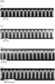
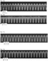
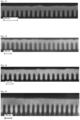
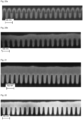
- Coplanarity and morphology was determined by measuring the height of the substrate by laser scanning microscopy.
- the patterned photoresist contained vias of 8 ⁇ m diameter and 15 ⁇ m depth and preformed copper ⁇ -bump of 5 ⁇ m height.
- the isolated (iso)-area consists of a 3 x 6 array of pillars with a center to center distance (pitch) of 32 ⁇ m.
- the dense area consists of an 8 x 16 array of pillars with a center to center distance (pitch) of 16 ⁇ m. For the calculation of the within die coplanarity 3 bumps of the iso-area and 3 bumps from the center of the dense area are taken.
- H iso and H dense are the average heights of the bumps in the iso/dense area and H Av is the overall average height of all bumps in the iso and dense area as described above.
- H i is the height of location i on a certain bump.
- H mean is the average height of all n locations of one bump.
- Glycerine (30 g) and potassium tert-butoxide (5.5 g) were placed into a 500 mL four-necked flask under nitrogen atmosphere and heated up to 160 °C. Then glycerine carbonate (346.2 g) was added over a period of 45 min. The mixture was allowed to post react for 5 h. A dark brown viscous intermediate product (246.9 g) was obtained.
- the intermediate product (87.5 g) and potassium tert-butoxide (0.6 g) were placed into a 3.5 l autoclave. After nitrogen neutralization the pressure was adjusted to 1.0 bar and the mixture was homogenized at 130 °C for 1 h. Then propylene oxide (576.2 g) and ethylene oxide (247.2 g) were added at 130 °C over a period of 4 h, reaching a maximum pressure of 7 bar. To complete the reaction, the mixture was allowed to post-react for 15 h at 130 °C at a pressure of 7 bar. Then, the temperature was decreased to 80 °C and volatile compounds were removed in vacuum at 80 °C.
- Suppressor 1 was obtained as a clear, brown oil (914.5 g).
- Trispentaerythritol (60 g) dissolved in Xylol and potassium tert-butoxide (0.6 g) were placed into a 3.5 l autoclave. After nitrogen neutralization the pressure was adjusted to 1.0 bar and the mixture was homogenized at 130 °C for 1 h. Then propylene oxide (403.5 g) and ethylene oxide (173.2 g) were added at 130 °C over a period of 4 h, reaching a maximum pressure of 7 bar. To complete the reaction, the mixture was allowed to post-react for 15 h at 130 °C at a pressure of 7 bar. Then, the temperature was decreased to 80 °C and volatile compounds were removed in vacuum at 80 °C. A viscous yellowish product A (633.3 g) was obtained.
- the intermediate product B (305.5 g) and potassium tert-butoxide (0.8 g) were placed into a 3.5 l autoclave. After nitrogen neutralization the pressure was adjusted to 1.0 bar and the mixture was homogenized at 130 °C for 1 h. Then propylene oxide (177.7 g) and ethylene oxide (75.7 g) were added at 130 °C over a period of 4 h, reaching a maximum pressure of 7 bar. To complete the reaction, the mixture was allowed to post-react for 4 h at 130 °C at a pressure of 7 bar. Then, the temperature was decreased to 80 °C and volatile compounds were removed in vacuum at 80 °C.
- Suppressor 2 was obtained as a clear, brown oil (549.7 g).
- Diethylene triamine (202.8 g) dissolved in water (10 g) was placed into a 3.5 l autoclave. After nitrogen neutralization the pressure was adjusted to 1.0 bar and the mixture was homogenized at 130 °C for 1 h. Then ethylene oxide (432.8 g) was added at 90 °C over a period of 5 h, reaching a maximum pressure of 5 bar. To complete the reaction, the mixture was allowed to post-react for 10 h at 130 °C at a pressure of 5 bar. Then, the temperature was decreased to and volatile compounds were removed in vacuum at 100 °C. A yellow viscous intermediated product A was obtained (631 g).
- a slightly viscous intermediate product B was obtained (1024.1 g).
- the intermediate product B 150 g
- potassium tert-butoxide 0.1 g
- glycerine carbonate 15.5 g
- the mixture was allowed to post react for 20 h.
- a beige-coloured intermediate product C (157.3 g) was obtained.
- Diethylene triamine (50 g) dissolved in water (52.3 g) was placed into a 1 L four-necked flask under nitrogen atmosphere and heated up to 120 °C. Then glycidol (186.9 g) was added over a period of 1.5 h. The mixture was allowed to post react for 4 h at 120°C. A brown viscous intermediate product (222.8 g) was obtained.
- the intermediate product (53 g) and potassium hydroxide (0.8 g) were placed into a 3.5 l autoclave. After nitrogen neutralization the pressure was adjusted to 1.0 bar and the mixture was homogenized at 130 °C for 1 h. Then propylene oxide (780 g) and ethylene oxide (591.5 g) were added at 130 °C over a period of 5 h, reaching a maximum pressure of 7 bar. To complete the reaction, the mixture was allowed to post-react for 20 h at 130 °C at a pressure of 7 bar. Then, the temperature was decreased to 80 °C and volatile compounds were removed in vacuum at 80 °C.
- Suppressor 4 was obtained as brown product (1359.8 g).
- Ethylen diamine (40 g) dissolved in water (47.9 g) was placed into a 500 mL four-necked flask under nitrogen atmosphere and heated up to 100 °C. Then glycidol (205.4 g) was added over a period of 2 h. The mixture was allowed to post react for 4 h at 100 °C. A brown viscous intermediate product A (244 g) was obtained.
- the intermediate product B (59.6 g) and potassium tert-butoxide (1.1 g) were placed into a 3.5 l autoclave. After nitrogen neutralization the pressure was adjusted to 1.0 bar and the mixture was homogenized at 130 °C for 1 h. Then propylene oxide (761.4 g) and ethylene oxide (326.3 g) were added at 130 °C over a period of 4 h, reaching a maximum pressure of 7 bar. To complete the reaction, the mixture was allowed to post-react for 15 h at 130 °C at a constant pressure of 7 bar. Then, the temperature was decreased to 80 °C and volatile compounds were removed in vacuum at 80 °C.
- Suppressor 5 was obtained as a yellowish slightly viscous liquid (1140.2 g).
- Triethanol amine (100 g) and potassium tert-butoxide (3.8 g) were placed into a 500 mL four-necked flask under nitrogen atmosphere and heated up to 100 °C. Then glycidol (248.3 g) was added over a period of 1 h. The mixture was allowed to post react for 4 h at 107 °C. A viscous yellowish intermediate product (348.5 g) was obtained.
- the intermediate product (100 g) and potassium tert-butoxide (1.1 g) were placed into a 3.5 l autoclave. After nitrogen neutralization the pressure was adjusted to 1.0 bar and the mixture was homogenized at 130 °C for 1 h. Then propylene oxide (726.6 g) was added at 130 °C over a period of 10 h, reaching a maximum pressure of 7.2 bar. The mixture was allowed to post react for 14 h at a constant pressure of 2 bar. Afterwards ethylene oxide (551.1 g) was added at 130 °C over a period of 10 h, reaching a maximum pressure of 5 bar. To complete the reaction, the mixture was allowed to post-react for 6 h at 130 °C at a constant pressure of 3 bar. Then, the temperature was decreased to 80 °C and volatile compounds were removed in vacuum at 80 °C.
- Suppressor 6 was obtained as a yellowish viscous liquid (1370.4 g) having an amine number of 0.15 mmol/g.
- Piperazine 100 g was placed into a 500 mL four-necked flask under nitrogen atmosphere and heated up to 110 °C. Then glycidol (172 g) was added over a period of 1 h. The mixture was allowed to post react for 4 h at 120 °C. A orange liquid (268.7 g) having an amine number of 8.34 mmol/g was obtained as pre-product.
- pre-product (198 g) and potassium tert-butoxide (1.8 g) were placed into a 3.5 l autoclave. After nitrogen neutralization the pressure was adjusted to 1.5 bar and the mixture was homogenized at 130 °C for 1 h. Then propylene oxide (737 g) was added at 130 °C over a period of 10 h, reaching a maximum pressure of 7 bar. The mixture was allowed to post react for 6 h. Then, the temperature was decreased to 80 °C and volatile compounds were removed in vacuum at 80 °C.
- the intermediate product was obtained as an orange oil (941 g).
- N-(2-aminoethyl) piperazine 85 g was placed into a 500 mL four-necked flask under nitrogen atmosphere and heated up to 100 °C. Then glycidol (125.7 g) was added over a period of 1 h. The mixture was allowed to post react for 4 h. A yellow intermediate product (203 g) having an amine number of 8.2 mmol/g was obtained.
- the intermediate product (66.5 g) and potassium tert-butoxide (1.1 g) were placed into a 3.5 l autoclave. After nitrogen neutralization the pressure was adjusted to 1.0 bar and the mixture was homogenized at 130 °C for 1 h. Then propylene oxide (311.1 g) was added at 130 °C over a period of 6 h, reaching a maximum pressure of 7.5 bar. The mixture was allowed to post react for 6 h. Afterwards ethylene oxide (236 g) was added at 130 °C over a period of 3 h, reaching a maximum pressure of 5 bar. To complete the reaction, the mixture was allowed to post-react for 6 h at 130 °C. Then, the temperature was decreased to 80 °C and volatile compounds were removed in vacuum at 80 °C. Suppressor 8 was obtained as orange liquid (600 g) having an amine number of 0.88 mmol/g.
- N-(2-aminoethyl) piperazine (81.6 g) was placed into a 500 mL four-necked flask under nitrogen atmosphere and heated up to 100 °C. Then glycidol (120.7 g) was added over a period of 1 h. The mixture was allowed to post react for 4 h. A yellow intermediate product (180 g) having an amine number of 7.85 mmol/g was obtained.
- the intermediate product (111 g) and potassium tert-butoxide (1.2 g) were placed into a 3.5 l autoclave. After nitrogen neutralization the pressure was adjusted to 1.0 bar and the mixture was homogenized at 130 °C for 1 h. Then propylene oxide (469.9 g) was added at 130 °C over a period of 10 h, reaching a maximum pressure of 7.2 bar. The mixture was allowed to post react for 10 h. Afterwards ethylene oxide (201.8 g) was added at 130 °C over a period of 6 h, reaching a maximum pressure of 5 bar. To complete the reaction, the mixture was allowed to post-react for 6 h at 130 °C. Then, the temperature was decreased to 80 °C and volatile compounds were removed in vacuum at 80 °C.
- Suppressor 9 was obtained as orange liquid (774.4 g) having an amine number of 1.16 mmol/g.
- Tris (2-aminoethyl) amine (30 g) was placed into a 250 mL four-necked flask under nitrogen atmosphere and heated up to 100 °C. Then glycidol (91.2 g) was added over a period of 1 h 45 min. The mixture was allowed to post react for 6.5 h. A yellow intermediate product (119.8 g) having an amine number of 5.18 mmol/g was obtained.
- the intermediate product (59.1 g) and potassium tert-butoxide (1.1 g) were placed into a 3.5 l autoclave. After nitrogen neutralization the pressure was adjusted to 1.0 bar and the mixture was homogenized at 130 °C for 1 h. Then propylene oxide (493 g) was added at 130 °C over a period of 6 h, reaching a maximum pressure of 7 bar. The mixture was allowed to post react for 12 h. Afterwards ethylene oxide (198 g) was added at 130 °C over a period of 6 h, reaching a maximum pressure of 4.4 bar. To complete the reaction, the mixture was allowed to post-react for 14 h at 130 °C. Then, the temperature was decreased to 80 °C and volatile compounds were removed in vacuum at 80 °C.
- Suppressor 10 was obtained as a brownish product (750.3 g) having an amine number of 0.16 mmol/g.
- the intermediate product (66.4 g) and potassium tert-butoxide (1.9 g) were placed into a 3.5 l autoclave. After nitrogen neutralization the pressure was adjusted to 2.0 bar and the mixture was homogenized at 130 °C for 1 h. Then propylene oxide (642 g) was added at 130 °C over a period of 10 h, reaching a maximum pressure of 5 bar. The mixture was allowed to post react for 10 h. Afterwards ethylene oxide (492 g) was added at 130 °C over a period of 8 h, reaching a maximum pressure of 5 bar. To complete the reaction, the mixture was allowed to post-react for 6 h at 130 °C. Then, the temperature was decreased to 80 °C and volatile compounds were removed in vacuum at 80 °C.
- Suppressor 11 was obtained as a brown liquid (1221 g) having an amine number of 0.63 mmol/g.
- Methyl dipropylene triamine 50 g was placed into a 500 mL four-necked flask under nitrogen atmosphere and heated up to 100 °C. Then glycidol (102.2 g) was added over a period of
- the intermediate product (49 g) dissolved in Xylol and potassium tert-butoxide (1.7 g) were placed into a 3.5 l autoclave. After nitrogen neutralization the pressure was adjusted to 1.0 bar and the mixture was homogenized at 130 °C for 1 h. Then propylene oxide (418.9 g) was added at 130 °C over a period of 13 h, reaching a maximum pressure of 7 bar. The mixture was allowed to post react for 6 h. Afterwards ethylene oxide (317.8 g) was added at 130 °C over a period of 11 h, reaching a maximum pressure of 6 bar. To complete the reaction, the mixture was allowed to post-react for 6 h at 130 °C. Then, the temperature was decreased to 80 °C and volatile compounds were removed in vacuum at 80 °C.
- Suppressor 12 was obtained as a yellowish liquid (708 g) having an amine number of 0.44 mmol/g.
- N-(2-aminoethyl) piperazine (306 g) was placed into 2 l autoclave. After nitrogen neutralization the mixture was heated up to 80 °C. Then glycidol (453.4 g) was added over a period of 5 h 15 min. The mixture was allowed to post react for 6 h. A viscous yellow intermediate product (738 g) having an amine number of 8.0 mmol/g was obtained.
- the intermediate product (64.6 g) and potassium tert-butoxide (1.5 g) were placed into a 2 l autoclave. After nitrogen neutralization the pressure was adjusted to 1.0 bar and the mixture was homogenized at 130 °C for 1 h. Then propylene oxide (604 g) was added at 130 °C over a period of 10 h, reaching a maximum pressure of 7.5 bar. The mixture was allowed to post react for 10 h. Afterwards ethylene oxide (257.7 g) was added at 130 °C over a period of 6 h, reaching a maximum pressure of 4.5 bar. To complete the reaction, the mixture was allowed to post-react for 6 h at 130 °C. Then, the temperature was decreased to 80 °C and volatile compounds were removed in vacuum at 80 °C.
- Suppressor 13 was obtained as a yellow liquid (927.4 g) having an amine number of 0.59 mmol/g.
- Tris(2-aminoethyl) amine 33 g was placed into a 250 mL four-necked flask under nitrogen atmosphere and heated up to 100 °C. Then glycidol (100.3 g) was added over a period of 2 h. The mixture was allowed to post react for 6 h. A viscous yellow intermediate product (130.2 g) having an amine number of 5.1 mmol/g was obtained.
- the intermediate product (66.8 g) and potassium tert-butoxide (0.7 g) were placed into a 3.5 l autoclave. After nitrogen neutralization the pressure was adjusted to 1.0 bar and the mixture was homogenized at 130 °C for 1 h. Then propylene oxide (249.6 g) was added at 130 °C over a period of 7 h, reaching a maximum pressure of 7.5 bar. The mixture was allowed to post react for 10 h. Afterwards ethylene oxide (106.6 g) was added at 130 °C over a period of 3 h, reaching a maximum pressure of 5 bar. To complete the reaction, the mixture was allowed to post-react for 10 h at 130 °C. Then, the temperature was decreased to 80 °C and volatile compounds were removed in vacuum at 80 °C.
- Suppressor 14 was obtained as a yellow liquid (413.2 g) having an amine number of 0.9 mmol/g.
- the intermediate product (94.7 g) and potassium tert-butoxide (0.9 g) were placed into a 3.5 l autoclave. After nitrogen neutralization the pressure was adjusted to 1.0 bar and the mixture was homogenized at 130 °C for 1 h. Then ethylene oxide (153.3 g) was added at 130 °C over a period of 6 h, reaching a maximum pressure of 7.5 bar. The mixture was allowed to post react for 6 h. Afterwards propylene oxide (357.8 g) was added at 130 °C over a period of 3 h, reaching a maximum pressure of 5 bar. To complete the reaction, the mixture was allowed to post-react for 6 h at 130 °C. Then, the temperature was decreased to 80 °C and volatile compounds were removed in vacuum at 80 °C.
- Suppressor 15 was obtained as a yellowish product (413.2 g) having an amine number of 0.9 mmol/g.
- Piperazine (58.1 g) was placed into a 500 mL four-necked flask under nitrogen atmosphere and heated up to 115 °C. Then glycidol (100 g) was added over a period of 110 min. The mixture was allowed to post react for 5 h at 120 °C. A beige-coloured intermediate product (151 g) having an amine number of 8.3 mmol/g was obtained.
- the intermediate product (117 g) and potassium tert-butoxide (1.9 g) were placed into a 3.5 l autoclave. After nitrogen neutralization the pressure was adjusted to 1.0 bar and the mixture was homogenized at 130 °C for 1 h. Then propylene oxide (290 g) was added at 130 °C over a period of 6 h, reaching a maximum pressure of 5 bar. Afterwards ethylene oxide (220 g) was added at 130 °C over a period of 5 h, reaching a maximum pressure of 4 bar. To complete the reaction, the mixture was allowed to post-react for 8 h at 130 °C. Then, the temperature was decreased to 80 °C and volatile compounds were removed in vacuum at 80 °C.
- Suppressor 16 was obtained as a dark brown liquid (618.6 g) having an amine number of 1.54 mmol/g.
- Ethylene diamine (97 g) was placed into 3.5 l autoclave. After nitrogen neutralization the mixture was heated up to 80 °C. Then glycidol (478.3 g) was added over a period of 22 h. The mixture was allowed to post react for 8 h. A highly viscous, brown intermediate product (556.6 g) having an amine number of 5.26 mmol/g was obtained.
- the intermediate product (123 g) and potassium tert-butoxide (1.5 g) were placed into a 3.5 l autoclave. After nitrogen neutralization the pressure was adjusted to 1.0 bar and the mixture was homogenized at 130 °C for 1 h. Then propylene oxide (741.6 g) was added at 130 °C over a period of 14 h, reaching a maximum pressure of 7 bar. The mixture was allowed to post react for 6 h. Then, the temperature was decreased to 80 °C and volatile compounds were removed in vacuum at 80 °C.
- Suppressor 17 was obtained as a dark brown liquid (859.3 g) having an amine number of 0.78 mmol/g.
- Example A18 Synthesis of suppressor 18 (not according to the invention)
- Glycerine (40 g) and potassium tert-butoxide (0.07 g) were placed into a 250 mL four-necked flask under nitrogen atmosphere and heated up to 100 °C. Then glycidol (100 g) was added over a period of 2 h. The mixture was allowed to post react for 4 h. A yellow, highly viscous intermediate product (314.3 g) was obtained.
- the intermediate product (94.3 g) and potassium tert-butoxide (1.1 g) were placed into a 3.5 l autoclave. After nitrogen neutralization the pressure was adjusted to 1.5 bar and the mixture was homogenized at 130 °C for 1 h. Then propylene oxide (446.1 g) was added at 130 °C over a period of 6 h, reaching a maximum pressure of 4.5 bar. The mixture was allowed to post react for 6 h. Afterwards ethylene oxide (469.1 g) was added at 130 °C over a period of 8 h, reaching a maximum pressure of 4.5 bar. To complete the reaction, the mixture was allowed to post-react for 6 h at 130 °C. Then, the temperature was decreased to 80 °C and volatile compounds were removed in vacuum at 80 °C.
- Suppressor 18 was obtained as a yellow viscous product (991.2 g).
- Glycerine (40 g) and potassium tert-butoxide (0.07 g) were placed into a 250 mL four-necked flask under nitrogen atmosphere and heated up to 100 °C. Then glycidol (100 g) was added over a period of 2 h. The mixture was allowed to post react for 4 h. A yellow, highly viscous intermediate product (314.3 g) was obtained.
- the intermediate product (78.6 g) and potassium tert-butoxide (1.04 g) were placed into a 3.5 l autoclave. After nitrogen neutralization the pressure was adjusted to 1.5 bar and the mixture was homogenized at 130 °C for 1 h. Then propylene oxide (392 g) was added at 130 °C over a period of 6 h, reaching a maximum pressure of 6.5 bar. The mixture was allowed to post react for 6 h. Afterwards ethylene oxide (220.3 g) was added at 130 °C over a period of 6 h, reaching a maximum pressure of 4.2 bar. To complete the reaction, the mixture was allowed to post-react for 14 h at 130 °C. Then, the temperature was decreased to 80 °C and volatile compounds were removed in vacuum at 80 °C.
- Suppressor 19 was obtained as a yellow viscous product (659.2 g).
- Example A20 Synthesis of Suppressor 20 (not according to the invention)
- Pentaerythritol (45 g) dissolved in 60 ml Xylol were placed into a 250 mL four-necked flask under nitrogen atmosphere. Potassium tert-butoxide (0.07 g) was added at 70 °C. Afterwards glycidol was added dropwise over a period of 2 h. The mixture was allowed to post react for 1.5 h. The volatile compounds were removed in vacuum at 80 °C. A yellow, slightly viscous intermediate product (119.5 g) was obtained.
- the intermediate product (64.9 g) and potassium hydoxide (5.3 g) were placed into a 3.5 I autoclave. After nitrogen neutralization the pressure was adjusted to 1.5 bar and the mixture was homogenized at 130 °C for 1 h. Then propylene oxide (566.3 g) was added at 130 °C over a period of 12 h, reaching a maximum pressure of 7.5 bar. The mixture was allowed to post react for 12 h. Afterwards ethylene oxide (429.5 g) was added at 130 °C over a period of 6 h, reaching a maximum pressure of 4.5 bar. To complete the reaction, the mixture was allowed to post-react for 12 h at 130 °C. Then, the temperature was decreased to 80 °C and volatile compounds were removed in vacuum at 80 °C.
- Suppressor 20 was obtained as a brownish product (956.2 g).
- 1,4-Bis(3-aminopropyl) piperazine (81.1 g) was placed into a 3.5 l autoclave. After nitrogen neutralization, the pressure was adjusted to 1.5 bar. Then glycidol (119.9 g) was added at 100 °C over a period of 2.5 h, reaching a maximum temperature of 108 °C. To complete the reaction, the mixture post-react for 4 h at 100 °C. Then, the temperature was decreased to 80 °C and volatile compounds were removed in vacuum at 80 °C. A yellowish intermediate product was obtained (201.1 g) having an amine number of 448.5 mg KOH/g.
- the intermediate product (101.5 g) and potassium tert-butoxide (1.1 g) were placed into a 3.5 l autoclave. After nitrogen neutralization, the pressure was adjusted to 1.0 bar and the mixture was homogenized at 130 °C for 1 h. Then propylene oxide (491.4 g) was added at 130 °C over a period of 6 h, reaching a maximum pressure of 5 bar. The mixture post-react for 12 h. Afterwards ethylene oxide (122.4 g) was added at 130 °C over a period of 3 h, reaching a maximum pressure of 5 bar. To complete the reaction, the mixture post-react for 6 h at 130 °C. Then, the temperature was decreased to 80 °C and volatile compounds were removed in vacuum at 80 °C. Surfactant 21 was obtained (715.1 g) having an amine number of 61.2 mg KOH/g.
- Trisaminoethylamine 33 g was placed into 500 mL four-necked flask under nitrogen atmosphere and heated up to 100 °C. Then glycidol (100 g) was added at 100 °C over a period of 2.5 h, reaching a maximum temperature of 104 °C. To complete the reaction, the mixture post-react for 3.5 h at 100 °C. Then, the temperature was decreased to 80 °C and volatile compounds were removed in vacuum at 80 °C. A yellowish intermediate product was obtained (133.3 g) having an amine number of 388.2 mg KOH/g.
- the intermediate product (80 g) and potassium tert-butoxide (0.6 g) were placed into a 3.5 l autoclave. After nitrogen neutralization, the pressure was adjusted to 1.0 bar and the mixture was homogenized at 130 °C for 1 h. Then propylene oxide (204.5 g) was added at 130 °C over a period of 7 h, reaching a maximum pressure of 5 bar. The mixture post-react for 12 h. Afterwards ethylene oxide (86.5 g) was added at 130 °C over a period of 7 h, reaching a maximum pressure of 5 bar. To complete the reaction, the mixture post-react for 10 h at 130 °C. Then, the temperature was decreased to 80 °C and volatile compounds were removed in vacuum at 80 °C. Surfactant 22 was obtained (244.1 g) having an amine number of 98.9 mg KOH/g.
- 1,4-Bis(3-aminopropyl) piperazine (274 g) was placed into a 3.5 I autoclave. After nitrogen neutralization, the pressure was adjusted to 1.5 bar. Then glycidol (406 g) was added at 100 °C over a period of 15 h, reaching a maximum temperature of 110 °C. To complete the reaction, the mixture post-react for 6 h at 100 °C. Then, the temperature was decreased to 80 °C and volatile compounds were removed in vacuum at 80 °C. A viscous yellowish intermediate product was obtained (680.4 g) having an amine number of 452.4 mg KOH/g.
- the intermediate product (125 g) and potassium tert-butoxide (0.6 g) were placed into a 3.5 l autoclave. After nitrogen neutralization, the pressure was adjusted to 1.0 bar and the mixture was homogenized at 130 °C for 1 h. Then propylene oxide (340.6 g) was added at 130 °C over a period of 6 h, reaching a maximum pressure of 5 bar. The mixture post-react for 10 h. Afterwards ethylene oxide (37.7 g) was added at 130 °C over a period of 1.5 h, reaching a maximum pressure of 5 bar. To complete the reaction, the mixture post-react for 6 h at 130 °C. Then, the temperature was decreased to 80 °C and volatile compounds were removed in vacuum at 80 °C. Surfactant 23 was obtained (503.1 g) having an amine number of 109.4 mg KOH/g.
- the intermediate product (125 g) and potassium tert-butoxide (1.0 g) were placed into a 3.5 l autoclave. After nitrogen neutralization, the pressure was adjusted to 1.0 bar and the mixture was homogenized at 130 °C for 1 h. Then propylene oxide (413.9 g) and ethylene oxide (174.4 g) were added at 130 °C over a period of 12 h, reaching a maximum pressure of 4.5 bar. To complete the reaction, the mixture post-react for 15 h at 130 °C at a pressure of 7 bar. Then, the temperature was decreased to 80 °C and volatile compounds were removed in vacuum at 80 °C. Surfactant 24 was obtained (713.4 g) having an amine number of 65.1 mg KOH/g.
- Example B1 Electroplating with Suppressor 1 (not according to the invention)
- a plating bath was prepared by combining DI water, 40 g/l copper as copper sulfate, 10 g/l sulfuric acid, 0.050 g/l chloride ion as HCl, 0.028 g/l of SPS and 3.50 ml/I of a 4.5 wt % solution in DI water of suppressor 1 as prepared in example A1.
- a copper layer was electroplated onto a wafer substrate with features provided with a copper seed layer by contacting the wafer substrate with the above described plating bath at 25 degrees C applying a direct current of -3 mA/cm 2 for 3.4 s.
- the thus electroplated copper layer was investigated by SEM inspection.
- fig. 1 provides the SEM image of the copper filled trenches.
- the neighboring trenches are equally filled without exhibiting voids or seams in the almost fully filled trenches after 3.4 s plating as shown in fig. 1 .
- Example B2 Electroplating with Suppressor 2 (not according to the invention)
- a plating bath was prepared by combining DI water, 40 g/l copper as copper sulfate, 10 g/l sulfuric acid, 0.050 g/l chloride ion as HCl, 0.028 g/l of SPS and 3.50 ml/I of a 4.5 wt % solution in DI water of suppressor 2 as prepared in example A2.
- a copper layer was electroplated onto a wafer substrate with features provided with a copper seed layer by contacting the wafer substrate with the above described plating bath at 25 degrees C applying a direct current of -3 mA/cm 2 for 3.4 s.
- the thus electroplated copper layer was investigated by SEM inspection.
- Fig. 2 provides the SEM image of partly filled trenches exhibiting the bottom-up filling with pronounced suppression of Cu deposition at the feature opening.
- the neighboring trenches are almost equally filled without exhibiting voids or seams as depicted in fig. 2 .
- the strong suppressing effect on the trench sidewalls can be clearly seen since the small feature openings are still obvious and did not close while partially filling the trenches.
- Example B3 Electroplating with Suppressor 3
- a plating bath was prepared by combining DI water, 40 g/l copper as copper sulfate, 10 g/l sulfuric acid, 0.050 g/l chloride ion as HCl, 0.028 g/l of SPS, and 5.50 ml/I of a 4.6 wt % solution in DI water of suppressor 3 as prepared in example A3.
- a copper layer was electroplated onto a wafer substrate with features provided with a copper seed layer by contacting the wafer substrate with the above described plating bath at 25 degrees C applying a direct current of -3 mA/cm 2 for 3.4 s.
- the thus electroplated copper layer was investigated by SEM inspection.
- Fig. 3 shows the SEM image of the resulting electroplated copper layer. The image exhibits fully filled trenches that are free of defects like voids or seams.
- Example B4 Electroplating with Suppressor 4
- a plating bath was prepared by combining DI water, 40 g/l copper as copper sulfate, 10 g/l sulfuric acid, 0.050 g/l chloride ion as HCl, 0.028 g/l of SPS, and 5.50 ml/I of a 4.6 wt % solution in DI water of suppressor 4 as prepared in example A4.
- a copper layer was electroplated onto a wafer substrate with features provided with a copper seed layer by contacting the wafer substrate with the above described plating bath at 25 degrees C applying a direct current of -3 mA/cm 2 for 3.4 s.
- the thus electroplated copper layer was investigated by SEM inspection.
- Example B5 Electroplating with Suppressor 5
- a plating bath was prepared by combining DI water, 40 g/l copper as copper sulfate, 10 g/l sulfuric acid, 0.050 g/l chloride ion as HCl, 0.028 g/l of SPS, and 3.00 ml/I of a 4.6 wt % solution in DI water of suppressor 5 as prepared in example A5.
- a copper layer was electroplated onto a wafer substrate with features provided with a copper seed layer by contacting the wafer substrate with the above described plating bath at 25 degrees C applying a direct current of -3 mA/cm 2 for 7 s .
- the thus electroplated copper layer was investigated by SEM inspection.
- the resulting SEM image is shown in fig. 5 . After 7 s deposition time the trenches are fully filled with copper without exhibiting any defects like voids or seams.
- Example B6 Electroplating with Suppressor 6
- a plating bath was prepared by combining DI water, 40 g/l copper as copper sulfate, 10 g/l sulfuric acid, 0.050 g/l chloride ion as HCl, 0.028 g/l of SPS, and 3.00 ml/I of a 4.8 wt % solution in DI water of suppressor 6 as prepared in example A6.
- a copper layer was electroplated onto a wafer substrate with features provided with a copper seed layer by contacting the wafer substrate with the above described plating bath at 25 degrees C applying a direct current of -3 mA/cm 2 for 3.4 s or 10 s respectively.
- the thus electroplated copper layer was investigated by SEM inspection.
- the resulting SEM images are shown in fig. 6a and 6b .
- the partly filled trenches after 3.4 s shown in fig. 6a , exhibit a strong suppression of the copper growth on the sidewalls of the trenches and thus a pronounced bottom-up fill. All feature openings are still open.
- the trenches After 10 s deposition time, shown in fig. 6b , the trenches are fully filled exhibiting few small but still tolerable defects at the sidewall of some features. Such sidewall defects results from a thin and thus weak copper seed layer.
- Example B7 Electroplating with Suppressor 7
- a plating bath was prepared by combining DI water, 40 g/l copper as copper sulfate, 10 g/l sulfuric acid, 0.050 g/l chloride ion as HCl, 0.028 g/l of SPS, and 3.00 ml/I of a 4.6 wt % solution in DI water of suppressor 7 as prepared in example A7.
- a copper layer was electroplated onto a wafer substrate with features provided with a copper seed layer by contacting the wafer substrate with the above described plating bath at 25 degrees C applying a direct current of -3 mA/cm 2 for 10 s .
- the thus electroplated copper layer was investigated by SEM inspection.
- the resulting SEM image is shown in fig. 7 . After 10 s deposition time the trenches are fully filled with copper without exhibiting any defects like voids or seams.
- Example B8 Electroplating with Suppressor 8
- a plating bath was prepared by combining DI water, 40 g/l copper as copper sulfate, 10 g/l sulfuric acid, 0.050 g/l chloride ion as HCl, 0.028 g/l of SPS, and 8.00 ml/I of a 1.1 wt % solution in DI water of suppressor 8 as prepared in example A8.
- a copper layer was electroplated onto a wafer substrate with features provided with a copper seed layer by contacting the wafer substrate with the above described plating bath at 25 degrees C applying a direct current of -3 mA/cm 2 for 3.4 s or 27 s .
- the thus electroplated copper layer was investigated by SEM inspection.
- the resulting SEM images are shown in figs. 8a and 8b .
- the partly filled trenches after 3.4 s, shown in fig. 8a exhibit a strong suppression of the copper growth on the sidewalls of the trenches and thus a pronounced bottom-up fill. All feature openings are still open.
- After 27 s deposition time, shown in fig. 8b the trenches are fully filled without exhibiting any defects like voids.
- Example B9 Electroplating with Suppressor 8
- a plating bath was prepared by combining DI water, 5 g/l copper as copper sulfate, 10 g/l sulfuric acid, 0.050 g/l chloride ion as HCl, 0.028 g/l of SPS, and 8.00 ml/I of a 1.1 wt % solution in DI water of suppressor 8 as prepared in example A8.
- a copper layer was electroplated onto a wafer substrate with features provided with a copper seed layer by contacting the wafer substrate with the above described plating bath at 25 degrees C applying a direct current of -3 mA/cm 2 for 3.4 s or 10 s .
- the thus electroplated copper layer was investigated by SEM inspection.
- the resulting SEM images are shown in figs. 9a and 9b .
- the partly filled trenches after 3.4 s, shown in fig. 9a exhibit a strong suppression of the copper growth on the sidewalls of the trenches and thus a pronounced bottom-up fill. All feature openings are still open.
- After 10 s deposition time, shown in fig. 9b the trenches are fully filled without exhibiting any defects like voids or seams.
- Example B10 Electroplating with Suppressor 9
- a plating bath was prepared by combining DI water, 40 g/l copper as copper sulfate, 10 g/l sulfuric acid, 0.050 g/l chloride ion as HCl, 0.028 g/l of SPS, and 8.00 ml/I of a 1.1 wt % solution in DI water of suppressor 9 as prepared in example A9.
- a copper layer was electroplated onto a wafer substrate with features provided with a copper seed layer by contacting the wafer substrate with the above described plating bath at 25 degrees C applying a direct current of -3 mA/cm 2 for 3.4 s or 27 s .
- the thus electroplated copper layer was investigated by SEM inspection.
- the resulting SEM images are shown in figs. 10a and 10b .
- the partly filled trenches after 3.4 s, shown in fig. 10a exhibit a strong suppression of the copper growth on the sidewalls of the trenches and thus a pronounced bottom-up fill. All feature openings are still open.
- After 27 s deposition time, shown in fig. 10b the trenches are fully filled without exhibiting any defects like voids or seams.
- Example B11 Electroplating with Suppressor 9
- a plating bath was prepared by combining DI water, 5 g/l copper as copper sulfate, 10 g/l sulfuric acid, 0.050 g/l chloride ion as HCl, 0.028 g/l of SPS, and 8.00 ml/I of a 1.1 wt % solution in DI water of suppressor 9 as prepared in example A9.
- a copper layer was electroplated onto a wafer substrate with features provided with a copper seed layer by contacting the wafer substrate with the above described plating bath at 25 degrees C applying a direct current of -3 mA/cm 2 for 3.4 s or 10 s .
- the thus electroplated copper layer was investigated by SEM inspection.
- the resulting SEM images are shown in figs. 11a and 11b .
- the partly filled trenches after 3.4 s, shown in fig. 11a exhibit a strong suppression of the copper growth on the sidewalls of the trenches and thus a pronounced bottom-up fill. All feature openings are still open.
- After 10 s deposition time, shown in fig. 11b the trenches are fully filled without exhibiting any defects like voids or seams.
- Example B12 Electroplating with Suppressor 10
- a plating bath was prepared by combining DI water, 40 g/l copper as copper sulfate, 10 g/l sulfuric acid, 0.050 g/l chloride ion as HCl, 0.028 g/l of SPS, and 3.50 ml/I of a 4.3 wt % solution in DI water of suppressor 10 as prepared in example A10.
- a copper layer was electroplated onto a wafer substrate with features provided with a copper seed layer by contacting the wafer substrate with the above described plating bath at 25 degrees C applying a direct current of -3 mA/cm 2 for 27 s .
- the thus electroplated copper layer was investigated by SEM inspection.
- the resulting SEM image is shown in fig. 12 . After 27 s deposition time the trenches are fully filled without exhibiting any defects like voids or seams.
- Example B13 Electroplating with Suppressor 11
- a plating bath was prepared by combining DI water, 40 g/l copper as copper sulfate, 10 g/l sulfuric acid, 0.050 g/l chloride ion as HCl, 0.028 g/l of SPS, and 1.50 ml/I of a 4.3 wt % solution in DI water of suppressor 11 as prepared in example A11.
- a copper layer was electroplated onto a wafer substrate with features provided with a copper seed layer by contacting the wafer substrate with the above described plating bath at 25 degrees C applying a direct current of -3 mA/cm 2 for 10 s .
- the thus electroplated copper layer was investigated by SEM inspection.
- the resulting SEM image is shown in fig. 13 .
- the trenches After 10 s deposition time the trenches are fully filled exhibiting few small but still tolerable defects at the sidewall of some features. Such sidewall defects results from a thin and thus weak copper seed layer.
- Example B14 Electroplating with Suppressor 11
- a plating bath was prepared by combining DI water, 5 g/l copper as copper sulfate, 10 g/l sulfuric acid, 0.050 g/l chloride ion as HCl, 0.028 g/l of SPS, and 5.00 ml/I of a 4.3 wt % solution in DI water of suppressor 11 as prepared in example A11.
- a copper layer was electroplated onto a wafer substrate with features provided with a copper seed layer by contacting the wafer substrate with the above described plating bath at 25 degrees C applying a direct current of -3 mA/cm 2 for 27 s .
- the thus electroplated copper layer was investigated by SEM inspection.
- the resulting SEM image is shown in fig. 14 . After 27 s deposition time the trenches are fully filled without exhibiting any defects like voids or seams.
- Example B15 Electroplating with Suppressor 12
- a plating bath was prepared by combining DI water, 5 g/l copper as copper sulfate, 10 g/l sulfuric acid, 0.050 g/l chloride ion as HCl, 0.028 g/l of SPS, and 3.00 ml/I of a 4.7 wt % solution in DI water of suppressor 12 as prepared in example A12.
- a copper layer was electroplated onto a wafer substrate with features provided with a copper seed layer by contacting the wafer substrate with the above described plating bath at 25 degrees C applying a direct current of -3 mA/cm 2 for 27 s .
- the thus electroplated copper layer was investigated by SEM inspection.
- the resulting SEM image is shown in fig. 15 . After 27 s deposition time the trenches are fully filled without exhibiting any defects like voids or seams.
- Example B16 Electroplating with Suppressor 13
- a plating bath was prepared by combining DI water, 40 g/l copper as copper sulfate, 10 g/l sulfuric acid, 0.050 g/l chloride ion as HCl, 0.028 g/l of SPS, and 3.00 ml/I of a 4.7 wt % solution in DI water of suppressor 13 as prepared in example A13.
- a copper layer was electroplated onto a wafer substrate with features provided with a copper seed layer by contacting the wafer substrate with the above described plating bath at 25 degrees C applying a direct current of -3 mA/cm 2 for 27 s .
- the thus electroplated copper layer was investigated by SEM inspection.
- the resulting SEM image is shown in fig. 16 . After 27 s deposition time the trenches are fully filled without exhibiting any defects like voids or seams.
- Example B17 Electroplating with Suppressor 13
- a plating bath was prepared by combining DI water, 5 g/l copper as copper sulfate, 10 g/l sulfuric acid, 0.050 g/l chloride ion as HCl, 0.028 g/l of SPS, and 3.00 ml/I of a 4.7 wt % solution in DI water of suppressor 13 as prepared in example A13.
- a copper layer was electroplated onto a wafer substrate with features provided with a copper seed layer by contacting the wafer substrate with the above described plating bath at 25 degrees C applying a direct current of -3 mA/cm 2 for 27 s .
- the thus electroplated copper layer was investigated by SEM inspection.
- the resulting SEM image is shown in fig. 17 . After 27 s deposition time the trenches are fully filled without exhibiting any defects like voids or seams.
- Example B18 Electroplating with Suppressor 14
- a plating bath was prepared by combining DI water, 40 g/l copper as copper sulfate, 10 g/l sulfuric acid, 0.050 g/l chloride ion as HCl, 0.028 g/l of SPS, and 2.00 ml/I of a 5.0 wt % solution in DI water of suppressor 14 as prepared in example A14.
- a copper layer was electroplated onto a wafer substrate with features provided with a copper seed layer by contacting the wafer substrate with the above described plating bath at 25 degrees C applying a direct current of -3 mA/cm 2 for 27 s .
- the thus electroplated copper layer was investigated by SEM inspection.
- the resulting SEM image is shown in fig. 18 . After 27 s deposition time the trenches are fully filled without exhibiting any defects like voids or seams.
- Example B19 Electroplating with Suppressor 15
- a plating bath was prepared by combining DI water, 40 g/l copper as copper sulfate, 10 g/l sulfuric acid, 0.050 g/l chloride ion as HCl, 0.028 g/l of SPS, and 2.50 ml/I of a 4.0 wt % solution in DI water of suppressor 15 as prepared in example A15.
- a copper layer was electroplated onto a wafer substrate with features provided with a copper seed layer by contacting the wafer substrate with the above described plating bath at 25 degrees C applying a direct current of -3 mA/cm 2 for 3.4 s or 27 s respectively.
- the thus electroplated copper layer was investigated by SEM inspection.
- the resulting SEM images are shown in figs. 19a and 19b .
- the partly filled trenches after 3.4 s, shown in fig. 19a exhibit a strong suppression of the copper growth on the sidewalls of the trenches and thus a pronounced bottom-up fill. All feature openings are still open.
- After 27 s deposition time, shown in fig. 19b the trenches are fully filled without exhibiting any defects like voids or seams.
- Example B20 Electroplating with Suppressor 15
- a plating bath was prepared by combining DI water, 5 g/l copper as copper sulfate, 10 g/l sulfuric acid, 0.050 g/l chloride ion as HCl, 0.028 g/l of SPS, and 2.50 ml/I of a 4.0 wt % solution in DI water of suppressor 15 as prepared in example A15.
- a copper layer was electroplated onto a wafer substrate with features provided with a copper seed layer by contacting the wafer substrate with the above described plating bath at 25 degrees C applying a direct current of -3 mA/cm 2 for 3.4 s or 27 s respectively.
- the thus electroplated copper layer was investigated by SEM inspection.
- the resulting SEM images are shown in figs. 20a and 20b .
- the partly filled trenches after 3.4 s, shown in fig. 20a exhibit a strong suppression of the copper growth on the sidewalls of the trenches and thus a pronounced bottom-up fill. All feature openings are still open.
- After 27 s deposition time, shown in fig. 20b the trenches are fully filled without exhibiting any defects like voids or seams.
- Example B21 Electroplating with Suppressor 16
- a plating bath was prepared by combining DI water, 40 g/l copper as copper sulfate, 10 g/l sulfuric acid, 0.050 g/l chloride ion as HCl, 0.028 g/l of SPS, and 8.00 ml/I of a 1.1 wt % solution in DI water of suppressor 16 as prepared in example A16.
- a copper layer was electroplated onto a wafer substrate with features provided with a copper seed layer by contacting the wafer substrate with the above described plating bath at 25 degrees C applying a direct current of -3 mA/cm 2 for 27 s respectively.
- the thus electroplated copper layer was investigated by SEM inspection.
- the resulting SEM image is shown in fig. 21 . After 27 s deposition time the trenches are fully filled without exhibiting any defects like voids or seams.
- Example B22 Electroplating with Suppressor 17
- a plating bath was prepared by combining DI water, 40 g/l copper as copper sulfate, 10 g/l sulfuric acid, 0.050 g/l chloride ion as HCl, 0.028 g/l of SPS, and 8.00 ml/I of a 1.1 wt % solution in DI water of suppressor 17 as prepared in example A17.
- a copper layer was electroplated onto a wafer substrate with features provided with a copper seed layer by contacting the wafer substrate with the above described plating bath at 25 degrees C applying a direct current of -3 mA/cm 2 for 27 s respectively.
- the thus electroplated copper layer was investigated by SEM inspection.
- the resulting SEM image is shown in fig. 22 . After 27 s deposition time the trenches are fully filled without exhibiting any defects like voids or seams.
- Example B23 Electroplating with Suppressor 18 (not according to the invention)
- a plating bath was prepared by combining DI water, 5 g/l copper as copper sulfate, 10 g/l sulfuric acid, 0.050 g/l chloride ion as HCl, 0.028 g/l of SPS, and 4.00 ml/I of a 1.1 wt % solution in DI water of suppressor 18 as prepared in example A18.
- a copper layer was electroplated onto a wafer substrate with features provided with a copper seed layer by contacting the wafer substrate with the above described plating bath at 25 degrees C applying a direct current of -3 mA/cm 2 for 27 s respectively.
- the thus electroplated copper layer was investigated by SEM inspection.
- the resulting SEM image is shown in fig. 23 . After 27 s deposition time the trenches are fully filled without exhibiting any defects like voids or seams.
- Example B24 Electroplating with Suppressor 18 (not according to the invention)
- a plating bath was prepared by combining DI water, 40 g/l copper as copper sulfate, 10 g/l sulfuric acid, 0.050 g/l chloride ion as HCl, 0.028 g/l of SPS, and 8.00 ml/I of a 1.1 wt % solution in DI water of suppressor 18 as prepared in example A18.
- a copper layer was electroplated onto a wafer substrate with features provided with a copper seed layer by contacting the wafer substrate with the above described plating bath at 25 degrees C applying a direct current of -3 mA/cm 2 for 27 s respectively.
- the thus electroplated copper layer was investigated by SEM inspection.
- the resulting SEM image is shown in fig. 24 .
- the trenches are fully filled exhibiting few small but still tolerable defects at the sidewall of some features. Such sidewall defects results from a thin and thus weak copper seed layer.
- Example B25 Electroplating with Suppressor 19 (not according to the invention)
- a plating bath was prepared by combining DI water, 5 g/l copper as copper sulfate, 10 g/l sulfuric acid, 0.050 g/l chloride ion as HCl, 0.028 g/l of SPS, and 4.00 ml/I of a 1.1 wt % solution in DI water of suppressor 19 as prepared in example A19.
- a copper layer was electroplated onto a wafer substrate with features provided with a copper seed layer by contacting the wafer substrate with the above described plating bath at 25 degrees C applying a direct current of -3 mA/cm 2 for 27 s respectively.
- the thus electroplated copper layer was investigated by SEM inspection.
- the resulting SEM image is shown in fig. 25 . After 27 s deposition time the trenches are fully filled without exhibiting any defects like voids or seams.
- Example B26 Electroplating with Suppressor 19 (not according to the invention)
- a plating bath was prepared by combining DI water, 40 g/l copper as copper sulfate, 10 g/l sulfuric acid, 0.050 g/l chloride ion as HCl, 0.028 g/l of SPS, and 4.00 ml/I of a 1.1 wt % solution in DI water of suppressor 19 as prepared in example A19.
- a copper layer was electroplated onto a wafer substrate with features provided with a copper seed layer by contacting the wafer substrate with the above described plating bath at 25 degrees C applying a direct current of -3 mA/cm 2 for 27 s respectively.
- the thus electroplated copper layer was investigated by SEM inspection.
- the resulting SEM image is shown in fig. 26 .
- the trenches are fully filled exhibiting few small but still tolerable defects at the sidewall of some features. Such sidewall defects results from a thin and thus weak copper seed layer.
- Example B27 Electroplating with Suppressor 20 (not according to the invention)
- a plating bath was prepared by combining DI water, 2.5 g/l copper as copper sulfate, 10 g/l sulfuric acid, 0.050 g/l chloride ion as HCl, 0.028 g/l of SPS, and 8.00 ml/I of a 1.8 wt % solution in DI water of suppressor 20 as prepared in example A20.
- a copper layer was electroplated onto a wafer substrate with features provided with a copper seed layer by contacting the wafer substrate with the above described plating bath at 25 degrees C applying a direct current of -3 mA/cm 2 for 27 s respectively.
- the thus electroplated copper layer was investigated by SEM inspection.
- the resulting SEM image is shown in fig. 27 . After 27 s deposition time the trenches are fully filled without exhibiting any defects like voids or seams.
- Example B28 Electroplating with Suppressor 20 (not according to the invention)
- a plating bath was prepared by combining DI water, 5.0 g/l copper as copper sulfate, 10 g/l sulfuric acid, 0.050 g/l chloride ion as HCl, 0.028 g/l of SPS, and 8.00 ml/I of a 1.8 wt % solution in DI water of suppressor 20 as prepared in example A20.
- a copper layer was electroplated onto a wafer substrate with features provided with a copper seed layer by contacting the wafer substrate with the above described plating bath at 25 degrees C applying a direct current of -3 mA/cm 2 for 27 s respectively.
- the thus electroplated copper layer was investigated by SEM inspection.
- the resulting SEM image is shown in fig. 28 . After 27 s deposition time the trenches are fully filled without exhibiting any defects like voids or seams.
- Example B29 Electroplating with Suppressor 20 (not according to the invention)
- a plating bath was prepared by combining DI water, 40.0 g/l copper as copper sulfate, 10 g/l sulfuric acid, 0.050 g/l chloride ion as HCl, 0.028 g/l of SPS, and 12.00 ml/I of a 1.8 wt % solution in DI water of suppressor 20 as prepared in example A20.
- a copper layer was electroplated onto a wafer substrate with features provided with a copper seed layer by contacting the wafer substrate with the above described plating bath at 25 degrees C applying a direct current of -3 mA/cm 2 for 27 s respectively.
- the thus electroplated copper layer was investigated by SEM inspection.
- the resulting SEM image is shown in fig. 29 . After 27 s deposition time the trenches are fully filled without exhibiting any defects like voids or seams.
- suppressor Even if the suppressors for this application are usually referred to as surfactants in tin electroplating the terminology "suppressor" is also used in the following examples for the sake of clearness.
- Lugalvan ® BNO 12 is ⁇ -naphthol ethoxylated with 12 moles ethylene oxide per mole ⁇ -naphthol.
- 5 ⁇ m tin was electroplated on a nickel covered copper micro-bump.
- the copper micro-bump had a diameter of 8 ⁇ m and a height of 5 ⁇ m.
- the nickel layer was 1 ⁇ m thick.
- a 2 cm x 2 cm large wafer coupon with a 15 ⁇ m thick patterned photo resist layer has been immersed in the above described plating bath and a direct current of 16 ASD has been applied for 37s at 25°C.
- the plated tin bump was examined with a laser scanning microscope (LSM). A mean roughness (R a ) of 0.4 ⁇ m and a coplanarity (COP) of 4% was determined. The results are summarized in Table 1.
- Lugalvan BNO 12 results in a rough surface of the plated tin bump.
- a tin plating bath as described for comparative example C1 containing additional 0,02 g/l benzalacetone and 10 ml/I isopropanol was prepared.
- the plating procedure was the one described in comparative example C1.
- the plated tin bump was examined with a laser scanning microscope (LSM).
- LSM laser scanning microscope
- R a mean roughness
- COP coplanarity
- Example C3 Tin Electroplating with suppressor 21
- a tin plating bath as described for comparative example C1 containing 1 g/l of suppressor 21 instead of Lugalvan BNO12 was used.
- the plating procedure was the one described in comparative example C1.
- the plated tin bump was examined with a laser scanning microscope (LSM).
- LSM laser scanning microscope
- the results are summarized in Table 1.
- Comparing the roughness R a with the reference surfactant used in Comparative Example C1 tin electroplating leads to a much smoother surface when using suppressor 21. Furthermore, a comparison of the reference suppressor combined with benzalacetone used in Comparative Example C2 with suppressor 21 shows that suppressor 21 leads to a much better coplanarity.
- Example C4 Tin Electroplating with suppressor 22
- a tin plating bath as described for comparative example C1 containing 1 g/l of suppressor 22 instead of Lugalvan BNO12 was used.
- the plating procedure was the one described in comparative example C1.
- the plated tin bump was examined with a laser scanning microscope (LSM).
- LSM laser scanning microscope
- R a laser scanning microscope
- COP coplanarity
- Comparing the roughness R a with the reference surfactant used in Comparative Example C1 tin electroplating leads to a much smoother surface when using suppressor 22. Furthermore, a comparison of the reference suppressor combined with benzalacetone used in Comparative Example C2 with suppressor 22 shows that suppressor 22 leads to a much better coplanarity.
- Example C5 Tin Electroplating with suppressor 23
- a tin plating bath as described for comparative example C1 containing 1 g/l of suppressor 23 instead of Lugalvan BNO12 was used.
- the plating procedure was the one described in comparative example C1.
- the plated tin bump was examined with a laser scanning microscope (LSM).
- LSM laser scanning microscope
- R a mean roughness
- COP coplanarity
- Comparing the roughness R a with the reference surfactant used in Comparative Example C1 tin electroplating leads to a much smoother surface when using suppressor 23. Furthermore, a comparison of the reference suppressor combined with benzalacetone used in Comparative Example C2 with suppressor 23 shows that suppressor 23 leads to a much better coplanarity.
- Example C6 Tin Electroplating with suppressor 24
- a tin plating bath as described for comparative example C1 containing 1 g/l of suppressor 24 instead of Lugalvan BNO12 was used.
- the plating procedure was the one described in comparative example C1.
- the plated tin bump was examined with a laser scanning microscope (LSM).
- LSM laser scanning microscope
- R a mean roughness
- COP coplanarity
Landscapes
- Chemical & Material Sciences (AREA)
- Engineering & Computer Science (AREA)
- Chemical Kinetics & Catalysis (AREA)
- Electrochemistry (AREA)
- Materials Engineering (AREA)
- Metallurgy (AREA)
- Organic Chemistry (AREA)
- Condensed Matter Physics & Semiconductors (AREA)
- Physics & Mathematics (AREA)
- General Physics & Mathematics (AREA)
- Manufacturing & Machinery (AREA)
- Computer Hardware Design (AREA)
- Microelectronics & Electronic Packaging (AREA)
- Power Engineering (AREA)
- Electroplating And Plating Baths Therefor (AREA)
- Compositions Of Macromolecular Compounds (AREA)
- Polyethers (AREA)
Applications Claiming Priority (2)
| Application Number | Priority Date | Filing Date | Title |
|---|---|---|---|
| EP16205553 | 2016-12-20 | ||
| PCT/EP2017/083603 WO2018114985A1 (en) | 2016-12-20 | 2017-12-19 | Composition for metal plating comprising suppressing agent for void free filling |
Publications (2)
| Publication Number | Publication Date |
|---|---|
| EP3559317A1 EP3559317A1 (en) | 2019-10-30 |
| EP3559317B1 true EP3559317B1 (en) | 2025-02-12 |
Family
ID=57860616
Family Applications (1)
| Application Number | Title | Priority Date | Filing Date |
|---|---|---|---|
| EP17835664.8A Active EP3559317B1 (en) | 2016-12-20 | 2017-12-19 | Composition for metal plating comprising suppressing agent for void free filling |
Country Status (8)
| Country | Link |
|---|---|
| US (1) | US11926918B2 (enExample) |
| EP (1) | EP3559317B1 (enExample) |
| JP (1) | JP2020502370A (enExample) |
| KR (1) | KR102457310B1 (enExample) |
| CN (2) | CN110100048B (enExample) |
| IL (1) | IL267332A (enExample) |
| TW (1) | TWI746746B (enExample) |
| WO (1) | WO2018114985A1 (enExample) |
Families Citing this family (23)
| Publication number | Priority date | Publication date | Assignee | Title |
|---|---|---|---|---|
| KR102641595B1 (ko) | 2017-09-04 | 2024-02-27 | 바스프 에스이 | 평탄화 제제를 포함하는 금속 전기 도금용 조성물 |
| US20190186032A1 (en) * | 2017-12-14 | 2019-06-20 | Soulbrain Co., Ltd. | Composition for cobalt plating and method for forming metal wiring using the same |
| WO2019121092A1 (en) * | 2017-12-20 | 2019-06-27 | Basf Se | Composition for tin or tin alloy electroplating comprising suppressing agent |
| CN112135929B (zh) * | 2018-04-20 | 2023-12-15 | 巴斯夫欧洲公司 | 包含抑制剂的用于锡或锡合金电镀的组合物 |
| CN111690958B (zh) * | 2019-03-15 | 2023-07-28 | 上海新阳半导体材料股份有限公司 | 一种锡镀液、其制备方法和应用 |
| US20220356592A1 (en) | 2019-09-27 | 2022-11-10 | Basf Se | Composition for copper bump electrodeposition comprising a leveling agent |
| US20220333262A1 (en) | 2019-09-27 | 2022-10-20 | Basf Se | Composition for copper bump electrodeposition comprising a leveling agent |
| CN110938848B (zh) * | 2019-12-26 | 2021-05-11 | 江苏艾森半导体材料股份有限公司 | 一种用于电解沉积铜的组合物及酸铜电镀液 |
| WO2021175935A1 (en) * | 2020-03-06 | 2021-09-10 | Basf Se | Electroplating with a polycarboxylate ether supressor |
| EP4127025B1 (en) | 2020-04-03 | 2025-10-01 | Basf Se | Composition for copper bump electrodeposition comprising a polyaminoamide type leveling agent |
| WO2021225827A1 (en) * | 2020-05-08 | 2021-11-11 | Lam Research Corporation | Electroplating cobalt, nickel, and alloys thereof |
| US11280014B2 (en) | 2020-06-05 | 2022-03-22 | Macdermid Enthone Inc. | Silver/tin electroplating bath and method of using the same |
| EP3922662A1 (en) | 2020-06-10 | 2021-12-15 | Basf Se | Polyalkanolamine |
| US20230265576A1 (en) * | 2020-07-13 | 2023-08-24 | Basf Se | Composition For Copper Electroplating On A Cobalt Seed |
| US11384446B2 (en) * | 2020-08-28 | 2022-07-12 | Macdermid Enthone Inc. | Compositions and methods for the electrodeposition of nanotwinned copper |
| KR102339867B1 (ko) * | 2021-07-30 | 2021-12-16 | 와이엠티 주식회사 | 레벨링제 및 이를 포함하는 비아홀 충진을 위한 전기도금 조성물 |
| KR102339868B1 (ko) * | 2021-07-30 | 2021-12-16 | 와이엠티 주식회사 | 레벨링제 및 이를 포함하는 비아홀 충진을 위한 전기도금 조성물 |
| US20240318342A1 (en) * | 2021-08-05 | 2024-09-26 | Macdermid Enthone Inc. | Compositions and methods for the eletrodeposition of nanotwinned copper |
| EP4409058B1 (en) | 2021-10-01 | 2025-11-05 | Basf Se | Composition for copper electrodeposition comprising a polyaminoamide type leveling agent |
| US20230203694A1 (en) * | 2021-12-29 | 2023-06-29 | Basf Se | Alkaline composition for copper electroplating comprising a grain refiner |
| EP4551742A1 (en) | 2022-07-07 | 2025-05-14 | Basf Se | Use of a composition comprising a polyaminoamide type compound for copper nanotwin electrodeposition |
| CN120457244A (zh) | 2022-12-19 | 2025-08-08 | 巴斯夫欧洲公司 | 用于铜纳米孪晶电沉积的组合物 |
| WO2025026863A1 (en) | 2023-08-03 | 2025-02-06 | Basf Se | Composition for copper electroplating on a metal seed |
Citations (1)
| Publication number | Priority date | Publication date | Assignee | Title |
|---|---|---|---|---|
| WO2010115717A1 (en) * | 2009-04-07 | 2010-10-14 | Basf Se | Composition for metal plating comprising suppressing agent for void free submicron feature filling |
Family Cites Families (32)
| Publication number | Priority date | Publication date | Assignee | Title |
|---|---|---|---|---|
| US4093594A (en) * | 1976-08-18 | 1978-06-06 | Celanese Polymer Specialties Company | Process for preparing cathodically depositable coating compositions |
| US4146442A (en) * | 1978-05-12 | 1979-03-27 | R. O. Hull & Company, Inc. | Zinc electroplating baths and process |
| US4347108A (en) | 1981-05-29 | 1982-08-31 | Rohco, Inc. | Electrodeposition of copper, acidic copper electroplating baths and additives therefor |
| US4871429A (en) | 1981-09-11 | 1989-10-03 | Learonal, Inc | Limiting tin sludge formation in tin or tin/lead electroplating solutions |
| JP3301707B2 (ja) | 1997-01-20 | 2002-07-15 | ディップソール株式会社 | 錫−銀合金酸性電気めっき浴 |
| JP4296358B2 (ja) | 1998-01-21 | 2009-07-15 | 石原薬品株式会社 | 銀及び銀合金メッキ浴 |
| US6444110B2 (en) | 1999-05-17 | 2002-09-03 | Shipley Company, L.L.C. | Electrolytic copper plating method |
| US7628903B1 (en) | 2000-05-02 | 2009-12-08 | Ishihara Chemical Co., Ltd. | Silver and silver alloy plating bath |
| US6679983B2 (en) | 2000-10-13 | 2004-01-20 | Shipley Company, L.L.C. | Method of electrodepositing copper |
| KR20030048110A (ko) | 2000-11-03 | 2003-06-18 | 쉬플리 캄파니, 엘.엘.씨. | 전자 디바이스 제조용 금속의 전기화학적 공침착 |
| US6881732B2 (en) * | 2002-06-13 | 2005-04-19 | Chelator Llc | Neuroprotection and cardioprotection afforded by chelators with high affinity and specificity for cations of first transition series elements |
| TWI400365B (zh) | 2004-11-12 | 2013-07-01 | Enthone | 微電子裝置上的銅電沈積 |
| BRPI0721265A2 (pt) * | 2006-12-21 | 2014-04-01 | Basf Se | Uso de polímeros termicamente sensíveis, processo para a lavagem de têxteis coloridos, copolímero, e, formulação de composição de lavagem. |
| FR2911878B1 (fr) * | 2007-01-31 | 2012-11-02 | Rhodia Recherches & Tech | Procede de preparation de polyhydroxy-urethanes. |
| US20110077376A1 (en) * | 2008-05-30 | 2011-03-31 | Katsumi Tokumoto | Process for producing hydroxyalkyltriethylenediamine, and catalyst composition for the production of polyurethane resin using it |
| EP2199315B1 (en) | 2008-12-19 | 2013-12-11 | Basf Se | Composition for metal electroplating comprising leveling agent |
| US20120027948A1 (en) | 2009-04-07 | 2012-02-02 | Basf Se | Composition for metal plating comprising suppressing agent for void free submicron feature filling |
| RU2542219C2 (ru) | 2009-04-07 | 2015-02-20 | Басф Се | Композиция для нанесения металлического покрытия, содержащая подавляющий агент, для беспустотного заполнения субмикронных элементов поверхности |
| WO2010115757A1 (en) * | 2009-04-07 | 2010-10-14 | Basf Se | Composition for metal plating comprising suppressing agent for void free submicron feature filling |
| US9869029B2 (en) * | 2009-07-30 | 2018-01-16 | Basf Se | Composition for metal plating comprising suppressing agent for void free submicron feature filling |
| EP2459779B1 (en) * | 2009-07-30 | 2015-09-09 | Basf Se | Composition for metal plating comprising suppressing agent for void free submicron feature filling |
| EP3848417B1 (en) | 2009-11-27 | 2025-01-08 | Basf Se | Composition for copper electroplating comprising leveling agent |
| SG185736A1 (en) | 2010-06-01 | 2012-12-28 | Basf Se | Composition for metal electroplating comprising leveling agent |
| SG10201510522XA (en) | 2010-12-21 | 2016-01-28 | Basf Se | Composition for metal electroplating comprising leveling agent |
| CN102212305B (zh) * | 2011-05-03 | 2013-07-31 | 中国科学院宁波材料技术与工程研究所 | 一种改进羟烷基酰胺/聚酯粉末涂料针孔和流平性的方法 |
| MY168658A (en) * | 2011-06-01 | 2018-11-28 | Basf Se | Composition for metal electroplating comprising an additive for bottom-up filling of though silicon vias and interconnect features |
| DE102011116764A1 (de) * | 2011-10-22 | 2013-04-25 | Gonzalo Urrutia Desmaison | Polykationen und Derivate |
| US8980077B2 (en) | 2012-03-30 | 2015-03-17 | Rohm And Haas Electronic Materials Llc | Plating bath and method |
| CN104797633B (zh) * | 2012-11-09 | 2018-04-24 | 巴斯夫欧洲公司 | 用于金属电镀的包含调平剂的组合物 |
| US20150122662A1 (en) * | 2013-11-05 | 2015-05-07 | Rohm And Haas Electronic Materials Llc | Plating bath and method |
| US10519557B2 (en) * | 2016-02-12 | 2019-12-31 | Macdermid Enthone Inc. | Leveler compositions for use in copper deposition in manufacture of microelectronics |
| WO2018073011A1 (en) | 2016-10-20 | 2018-04-26 | Basf Se | Composition for metal plating comprising suppressing agent for void free submicron feature filling |
-
2017
- 2017-12-19 KR KR1020197020953A patent/KR102457310B1/ko active Active
- 2017-12-19 EP EP17835664.8A patent/EP3559317B1/en active Active
- 2017-12-19 WO PCT/EP2017/083603 patent/WO2018114985A1/en not_active Ceased
- 2017-12-19 JP JP2019533638A patent/JP2020502370A/ja not_active Withdrawn
- 2017-12-19 CN CN201780078648.2A patent/CN110100048B/zh active Active
- 2017-12-19 US US16/468,467 patent/US11926918B2/en active Active
- 2017-12-19 CN CN202210633931.XA patent/CN115182004A/zh active Pending
- 2017-12-20 TW TW106144836A patent/TWI746746B/zh active
-
2019
- 2019-06-13 IL IL267332A patent/IL267332A/en unknown
Patent Citations (1)
| Publication number | Priority date | Publication date | Assignee | Title |
|---|---|---|---|---|
| WO2010115717A1 (en) * | 2009-04-07 | 2010-10-14 | Basf Se | Composition for metal plating comprising suppressing agent for void free submicron feature filling |
Also Published As
| Publication number | Publication date |
|---|---|
| CN115182004A (zh) | 2022-10-14 |
| KR20190091360A (ko) | 2019-08-05 |
| CN110100048A (zh) | 2019-08-06 |
| TWI746746B (zh) | 2021-11-21 |
| US11926918B2 (en) | 2024-03-12 |
| CN110100048B (zh) | 2022-06-21 |
| TW201835388A (zh) | 2018-10-01 |
| IL267332A (en) | 2019-08-29 |
| EP3559317A1 (en) | 2019-10-30 |
| JP2020502370A (ja) | 2020-01-23 |
| WO2018114985A1 (en) | 2018-06-28 |
| KR102457310B1 (ko) | 2022-10-20 |
| US20190309429A1 (en) | 2019-10-10 |
Similar Documents
| Publication | Publication Date | Title |
|---|---|---|
| EP3559317B1 (en) | Composition for metal plating comprising suppressing agent for void free filling | |
| US20210317582A1 (en) | Composition for metal plating comprising suppressing agent for void free submicron feature filling | |
| US20200173029A1 (en) | Composition for metal plating comprising suppressing agent for void free submicron feature filling | |
| EP2417284B1 (en) | Composition for metal plating comprising suppressing agent for void free submicron feature filling | |
| US9011666B2 (en) | Composition for metal electroplating comprising leveling agent | |
| JP2012522900A5 (enExample) | ||
| JP2012522897A5 (enExample) | ||
| WO2018073011A1 (en) | Composition for metal plating comprising suppressing agent for void free submicron feature filling | |
| WO2010115757A1 (en) | Composition for metal plating comprising suppressing agent for void free submicron feature filling | |
| US11840771B2 (en) | Composition for tin or tin alloy electroplating comprising suppressing agent | |
| EP3728702B1 (en) | Composition for tin or tin alloy electroplating comprising suppressing agent | |
| JP2023533784A (ja) | コバルトシード上の銅電気メッキ用組成物 |
Legal Events
| Date | Code | Title | Description |
|---|---|---|---|
| STAA | Information on the status of an ep patent application or granted ep patent |
Free format text: STATUS: UNKNOWN |
|
| STAA | Information on the status of an ep patent application or granted ep patent |
Free format text: STATUS: THE INTERNATIONAL PUBLICATION HAS BEEN MADE |
|
| PUAI | Public reference made under article 153(3) epc to a published international application that has entered the european phase |
Free format text: ORIGINAL CODE: 0009012 |
|
| STAA | Information on the status of an ep patent application or granted ep patent |
Free format text: STATUS: REQUEST FOR EXAMINATION WAS MADE |
|
| 17P | Request for examination filed |
Effective date: 20190722 |
|
| AK | Designated contracting states |
Kind code of ref document: A1 Designated state(s): AL AT BE BG CH CY CZ DE DK EE ES FI FR GB GR HR HU IE IS IT LI LT LU LV MC MK MT NL NO PL PT RO RS SE SI SK SM TR |
|
| AX | Request for extension of the european patent |
Extension state: BA ME |
|
| DAV | Request for validation of the european patent (deleted) | ||
| DAX | Request for extension of the european patent (deleted) | ||
| STAA | Information on the status of an ep patent application or granted ep patent |
Free format text: STATUS: EXAMINATION IS IN PROGRESS |
|
| 17Q | First examination report despatched |
Effective date: 20220905 |
|
| GRAP | Despatch of communication of intention to grant a patent |
Free format text: ORIGINAL CODE: EPIDOSNIGR1 |
|
| STAA | Information on the status of an ep patent application or granted ep patent |
Free format text: STATUS: GRANT OF PATENT IS INTENDED |
|
| INTG | Intention to grant announced |
Effective date: 20240904 |
|
| GRAS | Grant fee paid |
Free format text: ORIGINAL CODE: EPIDOSNIGR3 |
|
| GRAA | (expected) grant |
Free format text: ORIGINAL CODE: 0009210 |
|
| STAA | Information on the status of an ep patent application or granted ep patent |
Free format text: STATUS: THE PATENT HAS BEEN GRANTED |
|
| AK | Designated contracting states |
Kind code of ref document: B1 Designated state(s): AL AT BE BG CH CY CZ DE DK EE ES FI FR GB GR HR HU IE IS IT LI LT LU LV MC MK MT NL NO PL PT RO RS SE SI SK SM TR |
|
| REG | Reference to a national code |
Ref country code: GB Ref legal event code: FG4D |
|
| REG | Reference to a national code |
Ref country code: CH Ref legal event code: EP |
|
| REG | Reference to a national code |
Ref country code: DE Ref legal event code: R096 Ref document number: 602017087742 Country of ref document: DE |
|
| REG | Reference to a national code |
Ref country code: IE Ref legal event code: FG4D |
|
| REG | Reference to a national code |
Ref country code: NL Ref legal event code: MP Effective date: 20250212 |
|
| PG25 | Lapsed in a contracting state [announced via postgrant information from national office to epo] |
Ref country code: RS Free format text: LAPSE BECAUSE OF FAILURE TO SUBMIT A TRANSLATION OF THE DESCRIPTION OR TO PAY THE FEE WITHIN THE PRESCRIBED TIME-LIMIT Effective date: 20250512 |
|
| PG25 | Lapsed in a contracting state [announced via postgrant information from national office to epo] |
Ref country code: FI Free format text: LAPSE BECAUSE OF FAILURE TO SUBMIT A TRANSLATION OF THE DESCRIPTION OR TO PAY THE FEE WITHIN THE PRESCRIBED TIME-LIMIT Effective date: 20250212 |
|
| PG25 | Lapsed in a contracting state [announced via postgrant information from national office to epo] |
Ref country code: PL Free format text: LAPSE BECAUSE OF FAILURE TO SUBMIT A TRANSLATION OF THE DESCRIPTION OR TO PAY THE FEE WITHIN THE PRESCRIBED TIME-LIMIT Effective date: 20250212 |
|
| PG25 | Lapsed in a contracting state [announced via postgrant information from national office to epo] |
Ref country code: ES Free format text: LAPSE BECAUSE OF FAILURE TO SUBMIT A TRANSLATION OF THE DESCRIPTION OR TO PAY THE FEE WITHIN THE PRESCRIBED TIME-LIMIT Effective date: 20250212 |
|
| REG | Reference to a national code |
Ref country code: LT Ref legal event code: MG9D |
|
| PG25 | Lapsed in a contracting state [announced via postgrant information from national office to epo] |
Ref country code: IS Free format text: LAPSE BECAUSE OF FAILURE TO SUBMIT A TRANSLATION OF THE DESCRIPTION OR TO PAY THE FEE WITHIN THE PRESCRIBED TIME-LIMIT Effective date: 20250612 Ref country code: NO Free format text: LAPSE BECAUSE OF FAILURE TO SUBMIT A TRANSLATION OF THE DESCRIPTION OR TO PAY THE FEE WITHIN THE PRESCRIBED TIME-LIMIT Effective date: 20250512 |
|
| PG25 | Lapsed in a contracting state [announced via postgrant information from national office to epo] |
Ref country code: NL Free format text: LAPSE BECAUSE OF FAILURE TO SUBMIT A TRANSLATION OF THE DESCRIPTION OR TO PAY THE FEE WITHIN THE PRESCRIBED TIME-LIMIT Effective date: 20250212 |
|
| PG25 | Lapsed in a contracting state [announced via postgrant information from national office to epo] |
Ref country code: HR Free format text: LAPSE BECAUSE OF FAILURE TO SUBMIT A TRANSLATION OF THE DESCRIPTION OR TO PAY THE FEE WITHIN THE PRESCRIBED TIME-LIMIT Effective date: 20250212 |
|
| PG25 | Lapsed in a contracting state [announced via postgrant information from national office to epo] |
Ref country code: LV Free format text: LAPSE BECAUSE OF FAILURE TO SUBMIT A TRANSLATION OF THE DESCRIPTION OR TO PAY THE FEE WITHIN THE PRESCRIBED TIME-LIMIT Effective date: 20250212 Ref country code: PT Free format text: LAPSE BECAUSE OF FAILURE TO SUBMIT A TRANSLATION OF THE DESCRIPTION OR TO PAY THE FEE WITHIN THE PRESCRIBED TIME-LIMIT Effective date: 20250612 |
|
| PG25 | Lapsed in a contracting state [announced via postgrant information from national office to epo] |
Ref country code: GR Free format text: LAPSE BECAUSE OF FAILURE TO SUBMIT A TRANSLATION OF THE DESCRIPTION OR TO PAY THE FEE WITHIN THE PRESCRIBED TIME-LIMIT Effective date: 20250513 Ref country code: BG Free format text: LAPSE BECAUSE OF FAILURE TO SUBMIT A TRANSLATION OF THE DESCRIPTION OR TO PAY THE FEE WITHIN THE PRESCRIBED TIME-LIMIT Effective date: 20250212 |
|
| REG | Reference to a national code |
Ref country code: AT Ref legal event code: MK05 Ref document number: 1766123 Country of ref document: AT Kind code of ref document: T Effective date: 20250212 |
|
| PG25 | Lapsed in a contracting state [announced via postgrant information from national office to epo] |
Ref country code: SE Free format text: LAPSE BECAUSE OF FAILURE TO SUBMIT A TRANSLATION OF THE DESCRIPTION OR TO PAY THE FEE WITHIN THE PRESCRIBED TIME-LIMIT Effective date: 20250212 |
|
| PG25 | Lapsed in a contracting state [announced via postgrant information from national office to epo] |
Ref country code: SM Free format text: LAPSE BECAUSE OF FAILURE TO SUBMIT A TRANSLATION OF THE DESCRIPTION OR TO PAY THE FEE WITHIN THE PRESCRIBED TIME-LIMIT Effective date: 20250212 |
|
| PG25 | Lapsed in a contracting state [announced via postgrant information from national office to epo] |
Ref country code: DK Free format text: LAPSE BECAUSE OF FAILURE TO SUBMIT A TRANSLATION OF THE DESCRIPTION OR TO PAY THE FEE WITHIN THE PRESCRIBED TIME-LIMIT Effective date: 20250212 |
|
| PG25 | Lapsed in a contracting state [announced via postgrant information from national office to epo] |
Ref country code: IT Free format text: LAPSE BECAUSE OF FAILURE TO SUBMIT A TRANSLATION OF THE DESCRIPTION OR TO PAY THE FEE WITHIN THE PRESCRIBED TIME-LIMIT Effective date: 20250212 |
|
| PG25 | Lapsed in a contracting state [announced via postgrant information from national office to epo] |
Ref country code: AT Free format text: LAPSE BECAUSE OF FAILURE TO SUBMIT A TRANSLATION OF THE DESCRIPTION OR TO PAY THE FEE WITHIN THE PRESCRIBED TIME-LIMIT Effective date: 20250212 |
|
| PG25 | Lapsed in a contracting state [announced via postgrant information from national office to epo] |
Ref country code: EE Free format text: LAPSE BECAUSE OF FAILURE TO SUBMIT A TRANSLATION OF THE DESCRIPTION OR TO PAY THE FEE WITHIN THE PRESCRIBED TIME-LIMIT Effective date: 20250212 Ref country code: CZ Free format text: LAPSE BECAUSE OF FAILURE TO SUBMIT A TRANSLATION OF THE DESCRIPTION OR TO PAY THE FEE WITHIN THE PRESCRIBED TIME-LIMIT Effective date: 20250212 |
|
| PG25 | Lapsed in a contracting state [announced via postgrant information from national office to epo] |
Ref country code: RO Free format text: LAPSE BECAUSE OF FAILURE TO SUBMIT A TRANSLATION OF THE DESCRIPTION OR TO PAY THE FEE WITHIN THE PRESCRIBED TIME-LIMIT Effective date: 20250212 |
|
| PG25 | Lapsed in a contracting state [announced via postgrant information from national office to epo] |
Ref country code: SK Free format text: LAPSE BECAUSE OF FAILURE TO SUBMIT A TRANSLATION OF THE DESCRIPTION OR TO PAY THE FEE WITHIN THE PRESCRIBED TIME-LIMIT Effective date: 20250212 |