EP2459779B1 - Composition for metal plating comprising suppressing agent for void free submicron feature filling - Google Patents
Composition for metal plating comprising suppressing agent for void free submicron feature filling Download PDFInfo
- Publication number
- EP2459779B1 EP2459779B1 EP10734120.8A EP10734120A EP2459779B1 EP 2459779 B1 EP2459779 B1 EP 2459779B1 EP 10734120 A EP10734120 A EP 10734120A EP 2459779 B1 EP2459779 B1 EP 2459779B1
- Authority
- EP
- European Patent Office
- Prior art keywords
- copper
- composition according
- anyone
- oxide
- metal
- Prior art date
- Legal status (The legal status is an assumption and is not a legal conclusion. Google has not performed a legal analysis and makes no representation as to the accuracy of the status listed.)
- Active
Links
- 238000007747 plating Methods 0.000 title claims description 54
- 239000000203 mixture Substances 0.000 title claims description 49
- 229910052751 metal Inorganic materials 0.000 title claims description 47
- 239000002184 metal Substances 0.000 title claims description 47
- 238000011049 filling Methods 0.000 title description 20
- 239000011800 void material Substances 0.000 title description 6
- 239000010949 copper Substances 0.000 claims description 94
- RYGMFSIKBFXOCR-UHFFFAOYSA-N Copper Chemical compound [Cu] RYGMFSIKBFXOCR-UHFFFAOYSA-N 0.000 claims description 88
- 229910052802 copper Inorganic materials 0.000 claims description 88
- -1 cyclic monosaccharide alcohols Chemical class 0.000 claims description 73
- 239000000758 substrate Substances 0.000 claims description 47
- 150000005846 sugar alcohols Polymers 0.000 claims description 33
- 239000000654 additive Substances 0.000 claims description 28
- 125000002947 alkylene group Chemical group 0.000 claims description 28
- 239000003795 chemical substances by application Substances 0.000 claims description 28
- 238000000151 deposition Methods 0.000 claims description 19
- 125000002887 hydroxy group Chemical group [H]O* 0.000 claims description 19
- 238000000034 method Methods 0.000 claims description 19
- 150000001875 compounds Chemical class 0.000 claims description 17
- IAYPIBMASNFSPL-UHFFFAOYSA-N Ethylene oxide Chemical compound C1CO1 IAYPIBMASNFSPL-UHFFFAOYSA-N 0.000 claims description 15
- GOOHAUXETOMSMM-UHFFFAOYSA-N Propylene oxide Chemical group CC1CO1 GOOHAUXETOMSMM-UHFFFAOYSA-N 0.000 claims description 14
- 230000008021 deposition Effects 0.000 claims description 13
- 230000008569 process Effects 0.000 claims description 13
- 125000004432 carbon atom Chemical group C* 0.000 claims description 11
- FBPFZTCFMRRESA-FSIIMWSLSA-N D-Glucitol Natural products OC[C@H](O)[C@H](O)[C@@H](O)[C@H](O)CO FBPFZTCFMRRESA-FSIIMWSLSA-N 0.000 claims description 10
- FBPFZTCFMRRESA-JGWLITMVSA-N D-glucitol Chemical compound OC[C@H](O)[C@@H](O)[C@H](O)[C@H](O)CO FBPFZTCFMRRESA-JGWLITMVSA-N 0.000 claims description 10
- 239000000600 sorbitol Substances 0.000 claims description 10
- 235000010356 sorbitol Nutrition 0.000 claims description 10
- 150000002772 monosaccharides Chemical class 0.000 claims description 9
- LFQSCWFLJHTTHZ-UHFFFAOYSA-N Ethanol Chemical compound CCO LFQSCWFLJHTTHZ-UHFFFAOYSA-N 0.000 claims description 8
- 230000000996 additive effect Effects 0.000 claims description 7
- 150000003254 radicals Chemical class 0.000 claims description 6
- 208000007976 Ketosis Diseases 0.000 claims description 4
- 125000001931 aliphatic group Chemical group 0.000 claims description 4
- HEBKCHPVOIAQTA-UHFFFAOYSA-N meso ribitol Natural products OCC(O)C(O)C(O)CO HEBKCHPVOIAQTA-UHFFFAOYSA-N 0.000 claims description 4
- 229920005604 random copolymer Polymers 0.000 claims description 4
- FBPFZTCFMRRESA-KVTDHHQDSA-N D-Mannitol Chemical compound OC[C@@H](O)[C@@H](O)[C@H](O)[C@H](O)CO FBPFZTCFMRRESA-KVTDHHQDSA-N 0.000 claims description 3
- 229930091371 Fructose Natural products 0.000 claims description 3
- RFSUNEUAIZKAJO-ARQDHWQXSA-N Fructose Chemical compound OC[C@H]1O[C@](O)(CO)[C@@H](O)[C@@H]1O RFSUNEUAIZKAJO-ARQDHWQXSA-N 0.000 claims description 3
- 239000005715 Fructose Substances 0.000 claims description 3
- WQZGKKKJIJFFOK-GASJEMHNSA-N Glucose Natural products OC[C@H]1OC(O)[C@H](O)[C@@H](O)[C@@H]1O WQZGKKKJIJFFOK-GASJEMHNSA-N 0.000 claims description 3
- 229930195725 Mannitol Natural products 0.000 claims description 3
- WQZGKKKJIJFFOK-VFUOTHLCSA-N beta-D-glucose Chemical compound OC[C@H]1O[C@@H](O)[C@H](O)[C@@H](O)[C@@H]1O WQZGKKKJIJFFOK-VFUOTHLCSA-N 0.000 claims description 3
- 239000008103 glucose Substances 0.000 claims description 3
- 239000000594 mannitol Substances 0.000 claims description 3
- 235000010355 mannitol Nutrition 0.000 claims description 3
- YPZMPEPLWKRVLD-PJEQPVAWSA-N D-Glycero-D-gulo-Heptose Chemical compound OC[C@@H](O)[C@@H](O)[C@H](O)[C@@H](O)[C@@H](O)C=O YPZMPEPLWKRVLD-PJEQPVAWSA-N 0.000 claims description 2
- WQZGKKKJIJFFOK-CBPJZXOFSA-N D-Gulose Chemical compound OC[C@H]1OC(O)[C@H](O)[C@H](O)[C@H]1O WQZGKKKJIJFFOK-CBPJZXOFSA-N 0.000 claims description 2
- WQZGKKKJIJFFOK-WHZQZERISA-N D-aldose Chemical compound OC[C@H]1OC(O)[C@@H](O)[C@@H](O)[C@H]1O WQZGKKKJIJFFOK-WHZQZERISA-N 0.000 claims description 2
- WQZGKKKJIJFFOK-IVMDWMLBSA-N D-allopyranose Chemical compound OC[C@H]1OC(O)[C@H](O)[C@H](O)[C@@H]1O WQZGKKKJIJFFOK-IVMDWMLBSA-N 0.000 claims description 2
- LKDRXBCSQODPBY-JDJSBBGDSA-N D-allulose Chemical compound OCC1(O)OC[C@@H](O)[C@@H](O)[C@H]1O LKDRXBCSQODPBY-JDJSBBGDSA-N 0.000 claims description 2
- HSNZZMHEPUFJNZ-QMTIVRBISA-N D-keto-manno-heptulose Chemical compound OC[C@@H](O)[C@@H](O)[C@H](O)[C@H](O)C(=O)CO HSNZZMHEPUFJNZ-QMTIVRBISA-N 0.000 claims description 2
- HAIWUXASLYEWLM-UHFFFAOYSA-N D-manno-Heptulose Natural products OCC1OC(O)(CO)C(O)C(O)C1O HAIWUXASLYEWLM-UHFFFAOYSA-N 0.000 claims description 2
- WQZGKKKJIJFFOK-QTVWNMPRSA-N D-mannopyranose Chemical compound OC[C@H]1OC(O)[C@@H](O)[C@@H](O)[C@@H]1O WQZGKKKJIJFFOK-QTVWNMPRSA-N 0.000 claims description 2
- SQUHHTBVTRBESD-UHFFFAOYSA-N Hexa-Ac-myo-Inositol Natural products CC(=O)OC1C(OC(C)=O)C(OC(C)=O)C(OC(C)=O)C(OC(C)=O)C1OC(C)=O SQUHHTBVTRBESD-UHFFFAOYSA-N 0.000 claims description 2
- LKDRXBCSQODPBY-AMVSKUEXSA-N L-(-)-Sorbose Chemical compound OCC1(O)OC[C@H](O)[C@@H](O)[C@@H]1O LKDRXBCSQODPBY-AMVSKUEXSA-N 0.000 claims description 2
- WQZGKKKJIJFFOK-VSOAQEOCSA-N L-altropyranose Chemical compound OC[C@@H]1OC(O)[C@H](O)[C@@H](O)[C@H]1O WQZGKKKJIJFFOK-VSOAQEOCSA-N 0.000 claims description 2
- HSNZZMHEPUFJNZ-UHFFFAOYSA-N L-galacto-2-Heptulose Natural products OCC(O)C(O)C(O)C(O)C(=O)CO HSNZZMHEPUFJNZ-UHFFFAOYSA-N 0.000 claims description 2
- JVWLUVNSQYXYBE-UHFFFAOYSA-N Ribitol Natural products OCC(C)C(O)C(O)CO JVWLUVNSQYXYBE-UHFFFAOYSA-N 0.000 claims description 2
- HAIWUXASLYEWLM-AZEWMMITSA-N Sedoheptulose Natural products OC[C@H]1[C@H](O)[C@H](O)[C@H](O)[C@@](O)(CO)O1 HAIWUXASLYEWLM-AZEWMMITSA-N 0.000 claims description 2
- TVXBFESIOXBWNM-UHFFFAOYSA-N Xylitol Natural products OCCC(O)C(O)C(O)CCO TVXBFESIOXBWNM-UHFFFAOYSA-N 0.000 claims description 2
- 150000001363 alloheptuloses Chemical class 0.000 claims description 2
- WQZGKKKJIJFFOK-PHYPRBDBSA-N alpha-D-galactose Chemical compound OC[C@H]1O[C@H](O)[C@H](O)[C@@H](O)[C@H]1O WQZGKKKJIJFFOK-PHYPRBDBSA-N 0.000 claims description 2
- 229930182830 galactose Natural products 0.000 claims description 2
- 150000002454 idoses Chemical class 0.000 claims description 2
- CDAISMWEOUEBRE-GPIVLXJGSA-N inositol Chemical compound O[C@H]1[C@H](O)[C@@H](O)[C@H](O)[C@H](O)[C@@H]1O CDAISMWEOUEBRE-GPIVLXJGSA-N 0.000 claims description 2
- 229960000367 inositol Drugs 0.000 claims description 2
- BJHIKXHVCXFQLS-PQLUHFTBSA-N keto-D-tagatose Chemical compound OC[C@@H](O)[C@H](O)[C@H](O)C(=O)CO BJHIKXHVCXFQLS-PQLUHFTBSA-N 0.000 claims description 2
- 150000002700 mannoheptoses Chemical class 0.000 claims description 2
- 125000005702 oxyalkylene group Chemical group 0.000 claims description 2
- HEBKCHPVOIAQTA-ZXFHETKHSA-N ribitol Chemical compound OC[C@H](O)[C@H](O)[C@H](O)CO HEBKCHPVOIAQTA-ZXFHETKHSA-N 0.000 claims description 2
- CDAISMWEOUEBRE-UHFFFAOYSA-N scyllo-inosotol Natural products OC1C(O)C(O)C(O)C(O)C1O CDAISMWEOUEBRE-UHFFFAOYSA-N 0.000 claims description 2
- HSNZZMHEPUFJNZ-SHUUEZRQSA-N sedoheptulose Chemical compound OC[C@@H](O)[C@@H](O)[C@@H](O)[C@H](O)C(=O)CO HSNZZMHEPUFJNZ-SHUUEZRQSA-N 0.000 claims description 2
- 150000003478 taloheptuloses Chemical class 0.000 claims description 2
- 239000000811 xylitol Substances 0.000 claims description 2
- HEBKCHPVOIAQTA-SCDXWVJYSA-N xylitol Chemical compound OC[C@H](O)[C@@H](O)[C@H](O)CO HEBKCHPVOIAQTA-SCDXWVJYSA-N 0.000 claims description 2
- 235000010447 xylitol Nutrition 0.000 claims description 2
- 229960002675 xylitol Drugs 0.000 claims description 2
- 150000001323 aldoses Chemical class 0.000 claims 1
- 150000002584 ketoses Chemical class 0.000 claims 1
- IJGRMHOSHXDMSA-UHFFFAOYSA-N Atomic nitrogen Chemical compound N#N IJGRMHOSHXDMSA-UHFFFAOYSA-N 0.000 description 30
- XLYOFNOQVPJJNP-UHFFFAOYSA-N water Substances O XLYOFNOQVPJJNP-UHFFFAOYSA-N 0.000 description 29
- 238000009713 electroplating Methods 0.000 description 23
- 235000012431 wafers Nutrition 0.000 description 20
- QAOWNCQODCNURD-UHFFFAOYSA-N Sulfuric acid Chemical compound OS(O)(=O)=O QAOWNCQODCNURD-UHFFFAOYSA-N 0.000 description 16
- HUCVOHYBFXVBRW-UHFFFAOYSA-M caesium hydroxide Chemical compound [OH-].[Cs+] HUCVOHYBFXVBRW-UHFFFAOYSA-M 0.000 description 16
- 229910052757 nitrogen Inorganic materials 0.000 description 16
- HEMHJVSKTPXQMS-UHFFFAOYSA-M Sodium hydroxide Chemical compound [OH-].[Na+] HEMHJVSKTPXQMS-UHFFFAOYSA-M 0.000 description 15
- 125000003118 aryl group Chemical group 0.000 description 13
- 229910021645 metal ion Inorganic materials 0.000 description 13
- KWYUFKZDYYNOTN-UHFFFAOYSA-M Potassium hydroxide Chemical compound [OH-].[K+] KWYUFKZDYYNOTN-UHFFFAOYSA-M 0.000 description 12
- 238000006243 chemical reaction Methods 0.000 description 12
- PEDCQBHIVMGVHV-UHFFFAOYSA-N Glycerine Chemical compound OCC(O)CO PEDCQBHIVMGVHV-UHFFFAOYSA-N 0.000 description 11
- 238000004519 manufacturing process Methods 0.000 description 10
- QTBSBXVTEAMEQO-UHFFFAOYSA-N Acetic acid Chemical compound CC(O)=O QTBSBXVTEAMEQO-UHFFFAOYSA-N 0.000 description 9
- 239000003792 electrolyte Substances 0.000 description 9
- 238000001878 scanning electron micrograph Methods 0.000 description 9
- VEXZGXHMUGYJMC-UHFFFAOYSA-N Hydrochloric acid Chemical compound Cl VEXZGXHMUGYJMC-UHFFFAOYSA-N 0.000 description 8
- 239000004065 semiconductor Substances 0.000 description 8
- 229910052717 sulfur Inorganic materials 0.000 description 8
- NINIDFKCEFEMDL-UHFFFAOYSA-N Sulfur Chemical group [S] NINIDFKCEFEMDL-UHFFFAOYSA-N 0.000 description 7
- WYURNTSHIVDZCO-UHFFFAOYSA-N Tetrahydrofuran Chemical compound C1CCOC1 WYURNTSHIVDZCO-UHFFFAOYSA-N 0.000 description 7
- 125000003277 amino group Chemical group 0.000 description 7
- 230000007547 defect Effects 0.000 description 7
- 125000000524 functional group Chemical group 0.000 description 7
- VEXZGXHMUGYJMC-UHFFFAOYSA-M Chloride anion Chemical compound [Cl-] VEXZGXHMUGYJMC-UHFFFAOYSA-M 0.000 description 6
- AFVFQIVMOAPDHO-UHFFFAOYSA-N Methanesulfonic acid Chemical compound CS(O)(=O)=O AFVFQIVMOAPDHO-UHFFFAOYSA-N 0.000 description 6
- 239000002253 acid Substances 0.000 description 6
- 238000007306 functionalization reaction Methods 0.000 description 6
- 239000001257 hydrogen Substances 0.000 description 6
- 229910052739 hydrogen Inorganic materials 0.000 description 6
- 238000006386 neutralization reaction Methods 0.000 description 6
- 150000003839 salts Chemical class 0.000 description 6
- 239000007858 starting material Substances 0.000 description 6
- 239000011593 sulfur Substances 0.000 description 6
- UFHFLCQGNIYNRP-UHFFFAOYSA-N Hydrogen Chemical compound [H][H] UFHFLCQGNIYNRP-UHFFFAOYSA-N 0.000 description 5
- 239000004721 Polyphenylene oxide Substances 0.000 description 5
- 230000000052 comparative effect Effects 0.000 description 5
- 229920001577 copolymer Polymers 0.000 description 5
- 229910000365 copper sulfate Inorganic materials 0.000 description 5
- ARUVKPQLZAKDPS-UHFFFAOYSA-L copper(II) sulfate Chemical compound [Cu+2].[O-][S+2]([O-])([O-])[O-] ARUVKPQLZAKDPS-UHFFFAOYSA-L 0.000 description 5
- 238000009826 distribution Methods 0.000 description 5
- 229910052760 oxygen Inorganic materials 0.000 description 5
- 229920000570 polyether Polymers 0.000 description 5
- 229920001451 polypropylene glycol Polymers 0.000 description 5
- 239000011541 reaction mixture Substances 0.000 description 5
- LYCAIKOWRPUZTN-UHFFFAOYSA-N Ethylene glycol Chemical compound OCCO LYCAIKOWRPUZTN-UHFFFAOYSA-N 0.000 description 4
- 206010053759 Growth retardation Diseases 0.000 description 4
- NBIIXXVUZAFLBC-UHFFFAOYSA-N Phosphoric acid Chemical compound OP(O)(O)=O NBIIXXVUZAFLBC-UHFFFAOYSA-N 0.000 description 4
- 229920003171 Poly (ethylene oxide) Polymers 0.000 description 4
- 150000007513 acids Chemical class 0.000 description 4
- 125000000217 alkyl group Chemical group 0.000 description 4
- 150000001412 amines Chemical class 0.000 description 4
- 230000015572 biosynthetic process Effects 0.000 description 4
- 239000007795 chemical reaction product Substances 0.000 description 4
- 125000004122 cyclic group Chemical group 0.000 description 4
- 238000004070 electrodeposition Methods 0.000 description 4
- 238000005516 engineering process Methods 0.000 description 4
- 238000001914 filtration Methods 0.000 description 4
- 235000011187 glycerol Nutrition 0.000 description 4
- 238000007689 inspection Methods 0.000 description 4
- 239000007788 liquid Substances 0.000 description 4
- 229920000233 poly(alkylene oxides) Polymers 0.000 description 4
- 125000001424 substituent group Chemical group 0.000 description 4
- OKKJLVBELUTLKV-UHFFFAOYSA-N Methanol Chemical compound OC OKKJLVBELUTLKV-UHFFFAOYSA-N 0.000 description 3
- ZMXDDKWLCZADIW-UHFFFAOYSA-N N,N-Dimethylformamide Chemical compound CN(C)C=O ZMXDDKWLCZADIW-UHFFFAOYSA-N 0.000 description 3
- AWMVMTVKBNGEAK-UHFFFAOYSA-N Styrene oxide Chemical compound C1OC1C1=CC=CC=C1 AWMVMTVKBNGEAK-UHFFFAOYSA-N 0.000 description 3
- YXFVVABEGXRONW-UHFFFAOYSA-N Toluene Chemical compound CC1=CC=CC=C1 YXFVVABEGXRONW-UHFFFAOYSA-N 0.000 description 3
- GSEJCLTVZPLZKY-UHFFFAOYSA-N Triethanolamine Chemical compound OCCN(CCO)CCO GSEJCLTVZPLZKY-UHFFFAOYSA-N 0.000 description 3
- 238000013019 agitation Methods 0.000 description 3
- QVGXLLKOCUKJST-UHFFFAOYSA-N atomic oxygen Chemical group [O] QVGXLLKOCUKJST-UHFFFAOYSA-N 0.000 description 3
- 239000003153 chemical reaction reagent Substances 0.000 description 3
- 230000001747 exhibiting effect Effects 0.000 description 3
- 125000005842 heteroatom Chemical group 0.000 description 3
- 125000004435 hydrogen atom Chemical group [H]* 0.000 description 3
- ZADYMNAVLSWLEQ-UHFFFAOYSA-N magnesium;oxygen(2-);silicon(4+) Chemical compound [O-2].[O-2].[O-2].[Mg+2].[Si+4] ZADYMNAVLSWLEQ-UHFFFAOYSA-N 0.000 description 3
- 239000000463 material Substances 0.000 description 3
- 239000012528 membrane Substances 0.000 description 3
- 229940098779 methanesulfonic acid Drugs 0.000 description 3
- 239000001301 oxygen Substances 0.000 description 3
- QMMOXUPEWRXHJS-UHFFFAOYSA-N pentene-2 Natural products CCC=CC QMMOXUPEWRXHJS-UHFFFAOYSA-N 0.000 description 3
- 125000001997 phenyl group Chemical group [H]C1=C([H])C([H])=C(*)C([H])=C1[H] 0.000 description 3
- 229920001515 polyalkylene glycol Polymers 0.000 description 3
- 238000006068 polycondensation reaction Methods 0.000 description 3
- 239000000047 product Substances 0.000 description 3
- 238000000746 purification Methods 0.000 description 3
- 159000000000 sodium salts Chemical class 0.000 description 3
- 239000000126 substance Substances 0.000 description 3
- 229960004418 trolamine Drugs 0.000 description 3
- 125000004400 (C1-C12) alkyl group Chemical group 0.000 description 2
- 125000004191 (C1-C6) alkoxy group Chemical group 0.000 description 2
- 125000004169 (C1-C6) alkyl group Chemical group 0.000 description 2
- 125000006700 (C1-C6) alkylthio group Chemical group 0.000 description 2
- 125000006710 (C2-C12) alkenyl group Chemical group 0.000 description 2
- 125000006736 (C6-C20) aryl group Chemical group 0.000 description 2
- WFDIJRYMOXRFFG-UHFFFAOYSA-N Acetic anhydride Chemical compound CC(=O)OC(C)=O WFDIJRYMOXRFFG-UHFFFAOYSA-N 0.000 description 2
- PAYRUJLWNCNPSJ-UHFFFAOYSA-N Aniline Chemical compound NC1=CC=CC=C1 PAYRUJLWNCNPSJ-UHFFFAOYSA-N 0.000 description 2
- QXNVGIXVLWOKEQ-UHFFFAOYSA-N Disodium Chemical class [Na][Na] QXNVGIXVLWOKEQ-UHFFFAOYSA-N 0.000 description 2
- BRLQWZUYTZBJKN-UHFFFAOYSA-N Epichlorohydrin Chemical compound ClCC1CO1 BRLQWZUYTZBJKN-UHFFFAOYSA-N 0.000 description 2
- LRHPLDYGYMQRHN-UHFFFAOYSA-N N-Butanol Chemical compound CCCCO LRHPLDYGYMQRHN-UHFFFAOYSA-N 0.000 description 2
- 239000002202 Polyethylene glycol Substances 0.000 description 2
- 229920002873 Polyethylenimine Polymers 0.000 description 2
- JUJWROOIHBZHMG-UHFFFAOYSA-N Pyridine Chemical compound C1=CC=NC=C1 JUJWROOIHBZHMG-UHFFFAOYSA-N 0.000 description 2
- XUIMIQQOPSSXEZ-UHFFFAOYSA-N Silicon Chemical compound [Si] XUIMIQQOPSSXEZ-UHFFFAOYSA-N 0.000 description 2
- WQDUMFSSJAZKTM-UHFFFAOYSA-N Sodium methoxide Chemical compound [Na+].[O-]C WQDUMFSSJAZKTM-UHFFFAOYSA-N 0.000 description 2
- CZMRCDWAGMRECN-UGDNZRGBSA-N Sucrose Chemical compound O[C@H]1[C@H](O)[C@@H](CO)O[C@@]1(CO)O[C@@H]1[C@H](O)[C@@H](O)[C@H](O)[C@@H](CO)O1 CZMRCDWAGMRECN-UGDNZRGBSA-N 0.000 description 2
- 229930006000 Sucrose Natural products 0.000 description 2
- ATJFFYVFTNAWJD-UHFFFAOYSA-N Tin Chemical class [Sn] ATJFFYVFTNAWJD-UHFFFAOYSA-N 0.000 description 2
- 229910052783 alkali metal Inorganic materials 0.000 description 2
- 239000000956 alloy Substances 0.000 description 2
- 229910045601 alloy Inorganic materials 0.000 description 2
- 229910000147 aluminium phosphate Inorganic materials 0.000 description 2
- 230000008901 benefit Effects 0.000 description 2
- 229920001400 block copolymer Polymers 0.000 description 2
- 125000002837 carbocyclic group Chemical group 0.000 description 2
- 239000003054 catalyst Substances 0.000 description 2
- 238000005229 chemical vapour deposition Methods 0.000 description 2
- 238000009833 condensation Methods 0.000 description 2
- 230000005494 condensation Effects 0.000 description 2
- 150000001879 copper Chemical class 0.000 description 2
- ORTQZVOHEJQUHG-UHFFFAOYSA-L copper(II) chloride Chemical compound Cl[Cu]Cl ORTQZVOHEJQUHG-UHFFFAOYSA-L 0.000 description 2
- BSXVKCJAIJZTAV-UHFFFAOYSA-L copper;methanesulfonate Chemical compound [Cu+2].CS([O-])(=O)=O.CS([O-])(=O)=O BSXVKCJAIJZTAV-UHFFFAOYSA-L 0.000 description 2
- ZBCBWPMODOFKDW-UHFFFAOYSA-N diethanolamine Chemical compound OCCNCCO ZBCBWPMODOFKDW-UHFFFAOYSA-N 0.000 description 2
- 150000002016 disaccharides Chemical class 0.000 description 2
- 230000000694 effects Effects 0.000 description 2
- 125000000816 ethylene group Chemical group [H]C([H])([*:1])C([H])([H])[*:2] 0.000 description 2
- 125000005843 halogen group Chemical group 0.000 description 2
- 238000010438 heat treatment Methods 0.000 description 2
- 125000004404 heteroalkyl group Chemical group 0.000 description 2
- 125000001072 heteroaryl group Chemical group 0.000 description 2
- WGCNASOHLSPBMP-UHFFFAOYSA-N hydroxyacetaldehyde Natural products OCC=O WGCNASOHLSPBMP-UHFFFAOYSA-N 0.000 description 2
- 239000013067 intermediate product Substances 0.000 description 2
- 125000001624 naphthyl group Chemical group 0.000 description 2
- 125000000449 nitro group Chemical group [O-][N+](*)=O 0.000 description 2
- 238000007254 oxidation reaction Methods 0.000 description 2
- ACVYVLVWPXVTIT-UHFFFAOYSA-N phosphinic acid Chemical compound O[PH2]=O ACVYVLVWPXVTIT-UHFFFAOYSA-N 0.000 description 2
- 229910052698 phosphorus Inorganic materials 0.000 description 2
- XHXFXVLFKHQFAL-UHFFFAOYSA-N phosphoryl trichloride Chemical compound ClP(Cl)(Cl)=O XHXFXVLFKHQFAL-UHFFFAOYSA-N 0.000 description 2
- 238000005240 physical vapour deposition Methods 0.000 description 2
- 229920001223 polyethylene glycol Polymers 0.000 description 2
- 229910052710 silicon Inorganic materials 0.000 description 2
- 239000010703 silicon Substances 0.000 description 2
- 125000000547 substituted alkyl group Chemical group 0.000 description 2
- 125000003107 substituted aryl group Chemical group 0.000 description 2
- 238000006467 substitution reaction Methods 0.000 description 2
- 229960004793 sucrose Drugs 0.000 description 2
- QAOWNCQODCNURD-UHFFFAOYSA-L sulfate group Chemical group S(=O)(=O)([O-])[O-] QAOWNCQODCNURD-UHFFFAOYSA-L 0.000 description 2
- 239000004094 surface-active agent Substances 0.000 description 2
- ISIJQEHRDSCQIU-UHFFFAOYSA-N tert-butyl 2,7-diazaspiro[4.5]decane-7-carboxylate Chemical compound C1N(C(=O)OC(C)(C)C)CCCC11CNCC1 ISIJQEHRDSCQIU-UHFFFAOYSA-N 0.000 description 2
- WGTYBPLFGIVFAS-UHFFFAOYSA-M tetramethylammonium hydroxide Chemical compound [OH-].C[N+](C)(C)C WGTYBPLFGIVFAS-UHFFFAOYSA-M 0.000 description 2
- 150000003573 thiols Chemical class 0.000 description 2
- 125000003258 trimethylene group Chemical group [H]C([H])([*:2])C([H])([H])C([H])([H])[*:1] 0.000 description 2
- 125000004178 (C1-C4) alkyl group Chemical group 0.000 description 1
- 125000004209 (C1-C8) alkyl group Chemical group 0.000 description 1
- QMMOXUPEWRXHJS-HYXAFXHYSA-N (z)-pent-2-ene Chemical compound CC\C=C/C QMMOXUPEWRXHJS-HYXAFXHYSA-N 0.000 description 1
- RBACIKXCRWGCBB-UHFFFAOYSA-N 1,2-Epoxybutane Chemical compound CCC1CO1 RBACIKXCRWGCBB-UHFFFAOYSA-N 0.000 description 1
- GXMPGTXMVQAVAL-UHFFFAOYSA-N 1-[2-hydroxybutyl(methyl)amino]butan-2-ol Chemical compound CCC(O)CN(C)CC(O)CC GXMPGTXMVQAVAL-UHFFFAOYSA-N 0.000 description 1
- XKQMKMVTDKYWOX-UHFFFAOYSA-N 1-[2-hydroxypropyl(methyl)amino]propan-2-ol Chemical compound CC(O)CN(C)CC(C)O XKQMKMVTDKYWOX-UHFFFAOYSA-N 0.000 description 1
- OWEGMIWEEQEYGQ-UHFFFAOYSA-N 100676-05-9 Natural products OC1C(O)C(O)C(CO)OC1OCC1C(O)C(O)C(O)C(OC2C(OC(O)C(O)C2O)CO)O1 OWEGMIWEEQEYGQ-UHFFFAOYSA-N 0.000 description 1
- RAXXELZNTBOGNW-UHFFFAOYSA-N 1H-imidazole Chemical compound C1=CNC=N1 RAXXELZNTBOGNW-UHFFFAOYSA-N 0.000 description 1
- GELKGHVAFRCJNA-UHFFFAOYSA-N 2,2-Dimethyloxirane Chemical compound CC1(C)CO1 GELKGHVAFRCJNA-UHFFFAOYSA-N 0.000 description 1
- LBLYYCQCTBFVLH-UHFFFAOYSA-N 2-Methylbenzenesulfonic acid Chemical compound CC1=CC=CC=C1S(O)(=O)=O LBLYYCQCTBFVLH-UHFFFAOYSA-N 0.000 description 1
- HHRGNKUNRVABBN-UHFFFAOYSA-N 2-[2-hydroxyethyl(propan-2-yl)amino]ethanol Chemical compound OCCN(C(C)C)CCO HHRGNKUNRVABBN-UHFFFAOYSA-N 0.000 description 1
- RRQXXKCYECDESZ-UHFFFAOYSA-N 2-[3-(2-hydroxyethoxy)-2,2-bis(2-hydroxyethoxymethyl)propoxy]ethanol Chemical compound OCCOCC(COCCO)(COCCO)COCCO RRQXXKCYECDESZ-UHFFFAOYSA-N 0.000 description 1
- RILZRCJGXSFXNE-UHFFFAOYSA-N 2-[4-(trifluoromethoxy)phenyl]ethanol Chemical compound OCCC1=CC=C(OC(F)(F)F)C=C1 RILZRCJGXSFXNE-UHFFFAOYSA-N 0.000 description 1
- MIZIOHLLYXVEHJ-UHFFFAOYSA-N 2-[benzyl(2-hydroxyethyl)amino]ethanol Chemical compound OCCN(CCO)CC1=CC=CC=C1 MIZIOHLLYXVEHJ-UHFFFAOYSA-N 0.000 description 1
- NSUHEKKWYUZSQN-UHFFFAOYSA-N 2-[butan-2-yl(2-hydroxyethyl)amino]ethanol Chemical compound CCC(C)N(CCO)CCO NSUHEKKWYUZSQN-UHFFFAOYSA-N 0.000 description 1
- GVNHOISKXMSMPX-UHFFFAOYSA-N 2-[butyl(2-hydroxyethyl)amino]ethanol Chemical compound CCCCN(CCO)CCO GVNHOISKXMSMPX-UHFFFAOYSA-N 0.000 description 1
- HHPDFYDITNAMAM-UHFFFAOYSA-N 2-[cyclohexyl(2-hydroxyethyl)amino]ethanol Chemical compound OCCN(CCO)C1CCCCC1 HHPDFYDITNAMAM-UHFFFAOYSA-N 0.000 description 1
- JUVSRZCUMWZBFK-UHFFFAOYSA-N 2-[n-(2-hydroxyethyl)-4-methylanilino]ethanol Chemical compound CC1=CC=C(N(CCO)CCO)C=C1 JUVSRZCUMWZBFK-UHFFFAOYSA-N 0.000 description 1
- OJPDDQSCZGTACX-UHFFFAOYSA-N 2-[n-(2-hydroxyethyl)anilino]ethanol Chemical compound OCCN(CCO)C1=CC=CC=C1 OJPDDQSCZGTACX-UHFFFAOYSA-N 0.000 description 1
- 229940006193 2-mercaptoethanesulfonic acid Drugs 0.000 description 1
- AAMHBRRZYSORSH-UHFFFAOYSA-N 2-octyloxirane Chemical compound CCCCCCCCC1CO1 AAMHBRRZYSORSH-UHFFFAOYSA-N 0.000 description 1
- SYURNNNQIFDVCA-UHFFFAOYSA-N 2-propyloxirane Chemical compound CCCC1CO1 SYURNNNQIFDVCA-UHFFFAOYSA-N 0.000 description 1
- FULCXPQDMXUVSB-UHFFFAOYSA-N 3-(3-sulfanylpropylsulfonyloxy)propane-1-sulfonic acid Chemical compound OS(=O)(=O)CCCOS(=O)(=O)CCCS FULCXPQDMXUVSB-UHFFFAOYSA-N 0.000 description 1
- MQLJIOAPXLAGAP-UHFFFAOYSA-N 3-[amino(azaniumylidene)methyl]sulfanylpropane-1-sulfonate Chemical compound NC(=N)SCCCS(O)(=O)=O MQLJIOAPXLAGAP-UHFFFAOYSA-N 0.000 description 1
- ZQDPJFUHLCOCRG-UHFFFAOYSA-N 3-hexene Chemical compound CCC=CCC ZQDPJFUHLCOCRG-UHFFFAOYSA-N 0.000 description 1
- OBDVFOBWBHMJDG-UHFFFAOYSA-N 3-mercapto-1-propanesulfonic acid Chemical compound OS(=O)(=O)CCCS OBDVFOBWBHMJDG-UHFFFAOYSA-N 0.000 description 1
- VPWNQTHUCYMVMZ-UHFFFAOYSA-N 4,4'-sulfonyldiphenol Chemical class C1=CC(O)=CC=C1S(=O)(=O)C1=CC=C(O)C=C1 VPWNQTHUCYMVMZ-UHFFFAOYSA-N 0.000 description 1
- AMPCGOAFZFKBGH-UHFFFAOYSA-N 4-[[4-(dimethylamino)phenyl]-(4-methyliminocyclohexa-2,5-dien-1-ylidene)methyl]-n,n-dimethylaniline Chemical compound C1=CC(=NC)C=CC1=C(C=1C=CC(=CC=1)N(C)C)C1=CC=C(N(C)C)C=C1 AMPCGOAFZFKBGH-UHFFFAOYSA-N 0.000 description 1
- QGZKDVFQNNGYKY-UHFFFAOYSA-O Ammonium Chemical group [NH4+] QGZKDVFQNNGYKY-UHFFFAOYSA-O 0.000 description 1
- 229930185605 Bisphenol Natural products 0.000 description 1
- LSNNMFCWUKXFEE-UHFFFAOYSA-M Bisulfite Chemical compound OS([O-])=O LSNNMFCWUKXFEE-UHFFFAOYSA-M 0.000 description 1
- 125000000882 C2-C6 alkenyl group Chemical group 0.000 description 1
- 125000000041 C6-C10 aryl group Chemical group 0.000 description 1
- OCUCCJIRFHNWBP-IYEMJOQQSA-L Copper gluconate Chemical class [Cu+2].OC[C@@H](O)[C@@H](O)[C@H](O)[C@@H](O)C([O-])=O.OC[C@@H](O)[C@@H](O)[C@H](O)[C@@H](O)C([O-])=O OCUCCJIRFHNWBP-IYEMJOQQSA-L 0.000 description 1
- PIICEJLVQHRZGT-UHFFFAOYSA-N Ethylenediamine Chemical compound NCCN PIICEJLVQHRZGT-UHFFFAOYSA-N 0.000 description 1
- CTKINSOISVBQLD-UHFFFAOYSA-N Glycidol Chemical compound OCC1CO1 CTKINSOISVBQLD-UHFFFAOYSA-N 0.000 description 1
- GUBGYTABKSRVRQ-PICCSMPSSA-N Maltose Natural products O[C@@H]1[C@@H](O)[C@H](O)[C@@H](CO)O[C@@H]1O[C@@H]1[C@@H](CO)OC(O)[C@H](O)[C@H]1O GUBGYTABKSRVRQ-PICCSMPSSA-N 0.000 description 1
- 229910019213 POCl3 Inorganic materials 0.000 description 1
- ABLZXFCXXLZCGV-UHFFFAOYSA-N Phosphorous acid Chemical compound OP(O)=O ABLZXFCXXLZCGV-UHFFFAOYSA-N 0.000 description 1
- 229920002396 Polyurea Polymers 0.000 description 1
- SLINHMUFWFWBMU-UHFFFAOYSA-N Triisopropanolamine Chemical compound CC(O)CN(CC(C)O)CC(C)O SLINHMUFWFWBMU-UHFFFAOYSA-N 0.000 description 1
- ZJCCRDAZUWHFQH-UHFFFAOYSA-N Trimethylolpropane Chemical compound CCC(CO)(CO)CO ZJCCRDAZUWHFQH-UHFFFAOYSA-N 0.000 description 1
- 150000001242 acetic acid derivatives Chemical class 0.000 description 1
- 125000002777 acetyl group Chemical group [H]C([H])([H])C(*)=O 0.000 description 1
- 230000002378 acidificating effect Effects 0.000 description 1
- 125000002015 acyclic group Chemical group 0.000 description 1
- 150000008044 alkali metal hydroxides Chemical class 0.000 description 1
- 150000001340 alkali metals Chemical class 0.000 description 1
- 125000003342 alkenyl group Chemical group 0.000 description 1
- 125000005108 alkenylthio group Chemical group 0.000 description 1
- 125000003545 alkoxy group Chemical group 0.000 description 1
- 150000003973 alkyl amines Chemical class 0.000 description 1
- 125000002877 alkyl aryl group Chemical group 0.000 description 1
- 229940045714 alkyl sulfonate alkylating agent Drugs 0.000 description 1
- 150000008052 alkyl sulfonates Chemical class 0.000 description 1
- 125000004414 alkyl thio group Chemical group 0.000 description 1
- 125000005233 alkylalcohol group Chemical group 0.000 description 1
- 125000000304 alkynyl group Chemical group 0.000 description 1
- DIZPMCHEQGEION-UHFFFAOYSA-H aluminium sulfate (anhydrous) Chemical compound [Al+3].[Al+3].[O-]S([O-])(=O)=O.[O-]S([O-])(=O)=O.[O-]S([O-])(=O)=O DIZPMCHEQGEION-UHFFFAOYSA-H 0.000 description 1
- 150000001408 amides Chemical class 0.000 description 1
- 238000000137 annealing Methods 0.000 description 1
- 150000004982 aromatic amines Chemical class 0.000 description 1
- 125000006615 aromatic heterocyclic group Chemical group 0.000 description 1
- 125000005228 aryl sulfonate group Chemical group 0.000 description 1
- 125000005110 aryl thio group Chemical group 0.000 description 1
- 230000004888 barrier function Effects 0.000 description 1
- SRSXLGNVWSONIS-UHFFFAOYSA-N benzenesulfonic acid Chemical compound OS(=O)(=O)C1=CC=CC=C1 SRSXLGNVWSONIS-UHFFFAOYSA-N 0.000 description 1
- 125000003236 benzoyl group Chemical group [H]C1=C([H])C([H])=C(C([H])=C1[H])C(*)=O 0.000 description 1
- 125000001797 benzyl group Chemical group [H]C1=C([H])C([H])=C(C([H])=C1[H])C([H])([H])* 0.000 description 1
- GUBGYTABKSRVRQ-QUYVBRFLSA-N beta-maltose Chemical compound OC[C@H]1O[C@H](O[C@H]2[C@H](O)[C@@H](O)[C@H](O)O[C@@H]2CO)[C@H](O)[C@@H](O)[C@@H]1O GUBGYTABKSRVRQ-QUYVBRFLSA-N 0.000 description 1
- 150000001720 carbohydrates Chemical class 0.000 description 1
- 235000014633 carbohydrates Nutrition 0.000 description 1
- 150000001735 carboxylic acids Chemical class 0.000 description 1
- ZNEWHQLOPFWXOF-UHFFFAOYSA-N coenzyme M Chemical compound OS(=O)(=O)CCS ZNEWHQLOPFWXOF-UHFFFAOYSA-N 0.000 description 1
- KUNSUQLRTQLHQQ-UHFFFAOYSA-N copper tin Chemical compound [Cu].[Sn] KUNSUQLRTQLHQQ-UHFFFAOYSA-N 0.000 description 1
- XTVVROIMIGLXTD-UHFFFAOYSA-N copper(II) nitrate Chemical compound [Cu+2].[O-][N+]([O-])=O.[O-][N+]([O-])=O XTVVROIMIGLXTD-UHFFFAOYSA-N 0.000 description 1
- JZCCFEFSEZPSOG-UHFFFAOYSA-L copper(II) sulfate pentahydrate Chemical compound O.O.O.O.O.[Cu+2].[O-]S([O-])(=O)=O JZCCFEFSEZPSOG-UHFFFAOYSA-L 0.000 description 1
- OPQARKPSCNTWTJ-UHFFFAOYSA-L copper(ii) acetate Chemical compound [Cu+2].CC([O-])=O.CC([O-])=O OPQARKPSCNTWTJ-UHFFFAOYSA-L 0.000 description 1
- MRYMYQPDGZIGDM-UHFFFAOYSA-L copper;4-methylbenzenesulfonate Chemical compound [Cu+2].CC1=CC=C(S([O-])(=O)=O)C=C1.CC1=CC=C(S([O-])(=O)=O)C=C1 MRYMYQPDGZIGDM-UHFFFAOYSA-L 0.000 description 1
- RIOSFUBRIQHOMS-UHFFFAOYSA-L copper;benzenesulfonate Chemical compound [Cu+2].[O-]S(=O)(=O)C1=CC=CC=C1.[O-]S(=O)(=O)C1=CC=CC=C1 RIOSFUBRIQHOMS-UHFFFAOYSA-L 0.000 description 1
- LGLFFNDHMLKUMI-UHFFFAOYSA-N crystal violet cation Chemical compound C1=CC(N(C)C)=CC=C1C(C=1C=CC(=CC=1)N(C)C)=C1C=CC(=[N+](C)C)C=C1 LGLFFNDHMLKUMI-UHFFFAOYSA-N 0.000 description 1
- 230000007423 decrease Effects 0.000 description 1
- 230000003247 decreasing effect Effects 0.000 description 1
- FWBOFUGDKHMVPI-UHFFFAOYSA-K dicopper;2-oxidopropane-1,2,3-tricarboxylate Chemical compound [Cu+2].[Cu+2].[O-]C(=O)CC([O-])(C([O-])=O)CC([O-])=O FWBOFUGDKHMVPI-UHFFFAOYSA-K 0.000 description 1
- 235000013681 dietary sucrose Nutrition 0.000 description 1
- GYZLOYUZLJXAJU-UHFFFAOYSA-N diglycidyl ether Chemical class C1OC1COCC1CO1 GYZLOYUZLJXAJU-UHFFFAOYSA-N 0.000 description 1
- MZGNSEAPZQGJRB-UHFFFAOYSA-N dimethyldithiocarbamic acid Chemical compound CN(C)C(S)=S MZGNSEAPZQGJRB-UHFFFAOYSA-N 0.000 description 1
- WIYCQLLGDNXIBA-UHFFFAOYSA-L disodium;3-(3-sulfonatopropyldisulfanyl)propane-1-sulfonate Chemical compound [Na+].[Na+].[O-]S(=O)(=O)CCCSSCCCS([O-])(=O)=O WIYCQLLGDNXIBA-UHFFFAOYSA-L 0.000 description 1
- 230000008030 elimination Effects 0.000 description 1
- 238000003379 elimination reaction Methods 0.000 description 1
- 239000003480 eluent Substances 0.000 description 1
- CCIVGXIOQKPBKL-UHFFFAOYSA-M ethanesulfonate Chemical compound CCS([O-])(=O)=O CCIVGXIOQKPBKL-UHFFFAOYSA-M 0.000 description 1
- 125000001495 ethyl group Chemical group [H]C([H])([H])C([H])([H])* 0.000 description 1
- 239000012467 final product Substances 0.000 description 1
- WSFSSNUMVMOOMR-UHFFFAOYSA-N formaldehyde Substances O=C WSFSSNUMVMOOMR-UHFFFAOYSA-N 0.000 description 1
- 230000008570 general process Effects 0.000 description 1
- 239000011261 inert gas Substances 0.000 description 1
- 239000012442 inert solvent Substances 0.000 description 1
- 230000000977 initiatory effect Effects 0.000 description 1
- 230000003993 interaction Effects 0.000 description 1
- 125000003010 ionic group Chemical group 0.000 description 1
- 150000002500 ions Chemical class 0.000 description 1
- 230000001788 irregular Effects 0.000 description 1
- 150000003951 lactams Chemical class 0.000 description 1
- 239000000391 magnesium silicate Substances 0.000 description 1
- 229910052919 magnesium silicate Inorganic materials 0.000 description 1
- 235000019792 magnesium silicate Nutrition 0.000 description 1
- 230000008018 melting Effects 0.000 description 1
- 238000002844 melting Methods 0.000 description 1
- 229910001507 metal halide Inorganic materials 0.000 description 1
- 150000005309 metal halides Chemical class 0.000 description 1
- 229910001960 metal nitrate Inorganic materials 0.000 description 1
- 150000002739 metals Chemical class 0.000 description 1
- CRVGTESFCCXCTH-UHFFFAOYSA-N methyl diethanolamine Chemical compound OCCN(C)CCO CRVGTESFCCXCTH-UHFFFAOYSA-N 0.000 description 1
- 125000002496 methyl group Chemical group [H]C([H])([H])* 0.000 description 1
- 229910052750 molybdenum Inorganic materials 0.000 description 1
- LNOPIUAQISRISI-UHFFFAOYSA-N n'-hydroxy-2-propan-2-ylsulfonylethanimidamide Chemical compound CC(C)S(=O)(=O)CC(N)=NO LNOPIUAQISRISI-UHFFFAOYSA-N 0.000 description 1
- 229910052759 nickel Inorganic materials 0.000 description 1
- 125000004433 nitrogen atom Chemical group N* 0.000 description 1
- QJGQUHMNIGDVPM-UHFFFAOYSA-N nitrogen group Chemical group [N] QJGQUHMNIGDVPM-UHFFFAOYSA-N 0.000 description 1
- 239000003921 oil Substances 0.000 description 1
- 229950004864 olamine Drugs 0.000 description 1
- 230000003647 oxidation Effects 0.000 description 1
- 125000006353 oxyethylene group Chemical group 0.000 description 1
- 125000004430 oxygen atom Chemical group O* 0.000 description 1
- 238000004806 packaging method and process Methods 0.000 description 1
- 238000012858 packaging process Methods 0.000 description 1
- WXZMFSXDPGVJKK-UHFFFAOYSA-N pentaerythritol Chemical compound OCC(CO)(CO)CO WXZMFSXDPGVJKK-UHFFFAOYSA-N 0.000 description 1
- 150000002989 phenols Chemical class 0.000 description 1
- OJMIONKXNSYLSR-UHFFFAOYSA-N phosphorous acid Chemical compound OP(O)O OJMIONKXNSYLSR-UHFFFAOYSA-N 0.000 description 1
- 125000002743 phosphorus functional group Chemical group 0.000 description 1
- 229920003023 plastic Polymers 0.000 description 1
- 239000004033 plastic Substances 0.000 description 1
- 229920002006 poly(N-vinylimidazole) polymer Polymers 0.000 description 1
- 229920000083 poly(allylamine) Polymers 0.000 description 1
- 229920002401 polyacrylamide Polymers 0.000 description 1
- 229920000767 polyaniline Polymers 0.000 description 1
- 229920000647 polyepoxide Polymers 0.000 description 1
- 108010094020 polyglycine Proteins 0.000 description 1
- 229920000232 polyglycine polymer Polymers 0.000 description 1
- 229920000151 polyglycol Polymers 0.000 description 1
- 239000010695 polyglycol Substances 0.000 description 1
- 229920000642 polymer Polymers 0.000 description 1
- 229920005862 polyol Polymers 0.000 description 1
- 229920000137 polyphosphoric acid Polymers 0.000 description 1
- 229920002717 polyvinylpyridine Polymers 0.000 description 1
- 229920000036 polyvinylpyrrolidone Polymers 0.000 description 1
- 239000001267 polyvinylpyrrolidone Substances 0.000 description 1
- 235000013855 polyvinylpyrrolidone Nutrition 0.000 description 1
- 229910052700 potassium Inorganic materials 0.000 description 1
- LPNYRYFBWFDTMA-UHFFFAOYSA-N potassium tert-butoxide Chemical compound [K+].CC(C)(C)[O-] LPNYRYFBWFDTMA-UHFFFAOYSA-N 0.000 description 1
- BDERNNFJNOPAEC-UHFFFAOYSA-N propan-1-ol Chemical compound CCCO BDERNNFJNOPAEC-UHFFFAOYSA-N 0.000 description 1
- KCXFHTAICRTXLI-UHFFFAOYSA-N propane-1-sulfonic acid Chemical compound CCCS(O)(=O)=O KCXFHTAICRTXLI-UHFFFAOYSA-N 0.000 description 1
- 238000005086 pumping Methods 0.000 description 1
- UMJSCPRVCHMLSP-UHFFFAOYSA-N pyridine Natural products COC1=CC=CN=C1 UMJSCPRVCHMLSP-UHFFFAOYSA-N 0.000 description 1
- 230000035484 reaction time Effects 0.000 description 1
- 125000000467 secondary amino group Chemical group [H]N([*:1])[*:2] 0.000 description 1
- 238000000926 separation method Methods 0.000 description 1
- 238000001542 size-exclusion chromatography Methods 0.000 description 1
- 229910052708 sodium Inorganic materials 0.000 description 1
- 239000011734 sodium Substances 0.000 description 1
- VRKNGZAPJYUNSN-UHFFFAOYSA-M sodium;3-(1,3-benzothiazol-2-ylsulfanyl)propane-1-sulfonate Chemical compound [Na+].C1=CC=C2SC(SCCCS(=O)(=O)[O-])=NC2=C1 VRKNGZAPJYUNSN-UHFFFAOYSA-M 0.000 description 1
- 239000007790 solid phase Substances 0.000 description 1
- 239000002904 solvent Substances 0.000 description 1
- 238000005507 spraying Methods 0.000 description 1
- 238000003756 stirring Methods 0.000 description 1
- 239000005720 sucrose Substances 0.000 description 1
- IIACRCGMVDHOTQ-UHFFFAOYSA-N sulfamic acid Chemical class NS(O)(=O)=O IIACRCGMVDHOTQ-UHFFFAOYSA-N 0.000 description 1
- BDHFUVZGWQCTTF-UHFFFAOYSA-M sulfonate Chemical group [O-]S(=O)=O BDHFUVZGWQCTTF-UHFFFAOYSA-M 0.000 description 1
- 125000004434 sulfur atom Chemical group 0.000 description 1
- 150000003467 sulfuric acid derivatives Chemical class 0.000 description 1
- 230000001629 suppression Effects 0.000 description 1
- 238000003786 synthesis reaction Methods 0.000 description 1
- 150000005622 tetraalkylammonium hydroxides Chemical class 0.000 description 1
- 125000000383 tetramethylene group Chemical group [H]C([H])([*:1])C([H])([H])C([H])([H])C([H])([H])[*:2] 0.000 description 1
- 238000004448 titration Methods 0.000 description 1
- 229920000428 triblock copolymer Polymers 0.000 description 1
- ITMCEJHCFYSIIV-UHFFFAOYSA-N triflic acid Chemical compound OS(=O)(=O)C(F)(F)F ITMCEJHCFYSIIV-UHFFFAOYSA-N 0.000 description 1
- 229910052721 tungsten Inorganic materials 0.000 description 1
- 239000008096 xylene Substances 0.000 description 1
- 150000003738 xylenes Chemical class 0.000 description 1
- 229910052725 zinc Inorganic materials 0.000 description 1
- 239000011701 zinc Substances 0.000 description 1
Images


Classifications
-
- C—CHEMISTRY; METALLURGY
- C25—ELECTROLYTIC OR ELECTROPHORETIC PROCESSES; APPARATUS THEREFOR
- C25D—PROCESSES FOR THE ELECTROLYTIC OR ELECTROPHORETIC PRODUCTION OF COATINGS; ELECTROFORMING; APPARATUS THEREFOR
- C25D3/00—Electroplating: Baths therefor
- C25D3/02—Electroplating: Baths therefor from solutions
- C25D3/38—Electroplating: Baths therefor from solutions of copper
-
- C—CHEMISTRY; METALLURGY
- C25—ELECTROLYTIC OR ELECTROPHORETIC PROCESSES; APPARATUS THEREFOR
- C25D—PROCESSES FOR THE ELECTROLYTIC OR ELECTROPHORETIC PRODUCTION OF COATINGS; ELECTROFORMING; APPARATUS THEREFOR
- C25D3/00—Electroplating: Baths therefor
- C25D3/02—Electroplating: Baths therefor from solutions
-
- H—ELECTRICITY
- H01—ELECTRIC ELEMENTS
- H01L—SEMICONDUCTOR DEVICES NOT COVERED BY CLASS H10
- H01L21/00—Processes or apparatus adapted for the manufacture or treatment of semiconductor or solid state devices or of parts thereof
- H01L21/02—Manufacture or treatment of semiconductor devices or of parts thereof
- H01L21/04—Manufacture or treatment of semiconductor devices or of parts thereof the devices having at least one potential-jump barrier or surface barrier, e.g. PN junction, depletion layer or carrier concentration layer
- H01L21/18—Manufacture or treatment of semiconductor devices or of parts thereof the devices having at least one potential-jump barrier or surface barrier, e.g. PN junction, depletion layer or carrier concentration layer the devices having semiconductor bodies comprising elements of Group IV of the Periodic System or AIIIBV compounds with or without impurities, e.g. doping materials
- H01L21/28—Manufacture of electrodes on semiconductor bodies using processes or apparatus not provided for in groups H01L21/20 - H01L21/268
- H01L21/283—Deposition of conductive or insulating materials for electrodes conducting electric current
- H01L21/288—Deposition of conductive or insulating materials for electrodes conducting electric current from a liquid, e.g. electrolytic deposition
- H01L21/2885—Deposition of conductive or insulating materials for electrodes conducting electric current from a liquid, e.g. electrolytic deposition using an external electrical current, i.e. electro-deposition
-
- H—ELECTRICITY
- H01—ELECTRIC ELEMENTS
- H01L—SEMICONDUCTOR DEVICES NOT COVERED BY CLASS H10
- H01L21/00—Processes or apparatus adapted for the manufacture or treatment of semiconductor or solid state devices or of parts thereof
- H01L21/70—Manufacture or treatment of devices consisting of a plurality of solid state components formed in or on a common substrate or of parts thereof; Manufacture of integrated circuit devices or of parts thereof
- H01L21/71—Manufacture of specific parts of devices defined in group H01L21/70
- H01L21/768—Applying interconnections to be used for carrying current between separate components within a device comprising conductors and dielectrics
- H01L21/76838—Applying interconnections to be used for carrying current between separate components within a device comprising conductors and dielectrics characterised by the formation and the after-treatment of the conductors
- H01L21/76877—Filling of holes, grooves or trenches, e.g. vias, with conductive material
-
- C—CHEMISTRY; METALLURGY
- C25—ELECTROLYTIC OR ELECTROPHORETIC PROCESSES; APPARATUS THEREFOR
- C25D—PROCESSES FOR THE ELECTROLYTIC OR ELECTROPHORETIC PRODUCTION OF COATINGS; ELECTROFORMING; APPARATUS THEREFOR
- C25D3/00—Electroplating: Baths therefor
- C25D3/02—Electroplating: Baths therefor from solutions
- C25D3/38—Electroplating: Baths therefor from solutions of copper
- C25D3/40—Electroplating: Baths therefor from solutions of copper from cyanide baths, e.g. with Cu+
Definitions
- suppressors are used to provide a substantially bottom-up filling of small features like vias or trenches. The smaller the features are the more sophisticated the additives have to be to avoid voids and seams.
- suppressors are polyether compounds like polyglycols or polyalkylene oxides like ethylene oxide propylene oxide copolymers.
- Such polyether compounds are manufactured by reacting an alcohol starter comprising one or more hydroxyl groups like glycol or glycerol with polyalkylene oxides.
- US 2002/0043468 discloses suppressing agents comprising oxygen or nitrogen containing functional groups located in the branches of a polymer backbone.
- the branched suppressors have a molecular weight in the range of about 10.000 or greater.
- US 2004/0217009 A1 discloses poly(alkylene oxide) random copolymers suppressing agents, which may be linear or star-shaped.
- US 6776893 B1 discloses suppressing agents selected from block copolymers of polyoxyethylene and polyoxypropylene, a polyoxyethylene or polyoxypropylene derivative of a polyhydric alcohol and a mixed polyoxyethylene and polyoxypropylene derivative of a polyhydric alcohol.
- polyhydric alcohols are sorbitol, glycerol and mannitol, preferably glycerol.
- One class of such suppressing agents contain mixed alkoxy groups such as block copolymers of polyethylene oxide and polypropylene oxide.
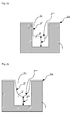
- the filling of the interconnects with copper becomes especially challenging, also since the copper seed deposition prior to the copper electrodeposition might exhibit inhomogeneity and non-conformality and thus further decreases the aperture sizes particularly at the top of the apertures.
- Especially apertures with a seed overhang at the top opening or convex-shaped apertures are challenging to fill and require an especially effective copper growth suppression at the side wall of the feature and the opening of the aperture.
- Fig. 3 shows a seeded substrate exhibiting impact of the seed on the opening of the features to be filled.
- the seed is shown by the light grey layer on the dark grey structures. Since there is an increasing seed overhang issue with further shrinking feature sizes, as depicted in fig. 3 , there is a serious risk of pinch-off void formation in the upper half of the trench close to the opening if the suppressor does not completely avoid sidewall copper growth (2" in fig. 2a to 2c ). As can be seen the openings are reduced to less than the half of the width without the seed layer resulting in effective aperture sizes of about 18 nanometer to 16 nanometer, respectively.
- the seeded feature has a convex shape.
- polyoxyalkylated polyalcohol having random copolymer structure and particular triblock copolymers show extraordinary superfilling properties, particularly if used to fill in features having extremely small aperture sizes and/or high aspect ratios.
- the present invention provides a new class of highly effective, strongly suppressing agents that cope with the seed overhang issue and provide substantially defect free trench filling despite a non-conformal copper seed.
- the present invention provides a composition comprising at least one source of metal ions and at least one polyoxyalkylated polyhydric alcohol having at least 5 hydroxyl groups.
- the at least one suppressing agent is obtainable by reacting a polyhydric alcohol comprising at least 5 hydroxly functional groups with at least a first alkylene oxide and a second alkylene oxide from a mixture of the first alkylene oxide and the second alkylene oxide to form random copolymers of the ethylene oxide and the further C3 to C4 alkylene oxide. In this way a polyhydric alcohol is formed comprising random polyoxyalkylene copolymer side chains.
- the advantage of the additives according to the present invention is their suppressing capability that result in a extraordinarily pronounced bottom-up fill copper growth while perfectly suppressing the sidewall copper growth, both leading to a flat growth front and thus providing substantially defect free trench or via fill.
- the strong sidewall copper growth suppression of the invention enables non-conformal copper seeded features to be substantially void free filled.
- the invention provides an overall homogeneous bottom-up fill in neighboring features of dense feature areas.
- the additives according to the present invention are particularly useful for filling of small features, particularly those having aperture sizes of 30 nanometer or below.
- the additives are generally obtainable by reacting a polyhydric alcohol (also referred to as polyalcohol) comprising at least 5 hydroxyl groups with the alkylene oxides either from a mixture or in sequence. In this way the hydroxyl groups of the polyalcohol are etherified to generate polyoxyalkylene side chains.
- a polyhydric alcohol also referred to as polyalcohol
- compositions are represented by formula (I) X(OH) m (I) wherein
- the polyalcohol is a linear monosaccharide alcohol represented by formula (II) HOCH 2 -(CHOH) n -CH 2 OH (II) wherein n is an integer from 3 to 8.
- Examples of corresponding monosaccharide alcohols (II) comprise sorbitol, mannitol, xylitol, ribitol as well as their stereo isomers, and the like.
- a particularly preferred monosaccharide alcohol (II) is sorbitol.
- the polyalcohol is a cyclic monosaccharide alcohol represented by formula (III) (CHOH) o (III) wherein o is an integer from 5 to 10.
- Examples of corresponding monosaccharide alcohols (III) comprise inositol (cyclohexanehexole).
- suitable polyalcohols are monosaccharides and their stereo isomers.
- Preferred monosaccharides are monosaccharide aldoses of formula (IV) CHO-(CHOH) p -CH 2 OH (IV) wherein p is an integer of 4 to 5.
- Examples of corresponding monosaccharide aldoses (IV) are allose, altrose, galactose, glucose, gulose, idose, mannose, talose, glucoheptose, mannoheptose and the like.
- a very preferred monosaccharide aldose (IV) is glucose.
- Particularly preferred monosaccharides are monosaccharide ketoses (V) CH 2 OH-(CHOH) q -CO-(CHOH) r -CH 2 OH (V) wherein q and r are integers and q + r is 3 or 4.
- Examples of corresponding monosaccharide ketoses (V) are fructose, psicose, sorbose, tagatose, mannoheptulose, sedoheptulose, taloheptulose, alloheptulose and the like.
- a particularly preferred monosaccharide ketose (V) is fructose and derivatives thereof.
- suitable polyalcohols are selected from disaccharides.
- Particularly preferred disaccharides are sucrose and maltose, and derivatives thereof.
- the additives according to the present invention are particular reaction products of polyalcohols and alkylene oxides.
- Polyalkoxylated polyalcohols can be received by reacting the OH groups present in the polyalcohol with alkylene oxides to form terminal polyether groups comprising the respective oxyalkylene units.
- Polyalkoxylated polyalcohols are per se known in the art.
- suitable alkylene oxides may be C 2 - to C 12 -alkylene oxides or styrene oxide, without being limited thereto.
- corresponding alkylene oxides comprise ethylene oxide and propylene oxide, 1-butene oxide, 2,3-butene oxide, 2-methyl-1,2-propene oxide (isobutene oxide), 1-pentene oxide, 2,3-pentene oxide, 2-methyl-1,2-butene oxide, 3-methyl-1,2-butene oxide, 2,3-hexene oxide, 3,4-hexene oxide, 2-methyl-1,2-pentene oxide, 2-ethyl-1,2-butene oxide, 3-methyl-1,2-pentene oxide, decene oxide, 4-methyl-1,2-pentene oxide or styrene oxide.
- alkylene oxide(s) selected from ethylene oxide, propylene oxide and butylene oxide, or combinations thereof.
- the content of ethylene oxide in the copolymer of ethylene oxide and other alkylene oxide(s) is from 10 to 90 % by weight, more preferably from 20 to 50 % by weight, most preferably from 25 to 40 % by weight.
- the first alkylene oxide is ethylene oxide and the second alkylene oxide is selected from propylene oxide and butylene oxide, or combinations thereof. Most preferably the second alkylene oxide is propylene oxide.
- higher alkylene oxides are generally used, at most, in small amounts for fine adjustment of the properties.
- the amount of ethylene oxide and/or propylene oxide and/ or butylene oxide is at least 80% by weight, preferably at least 90%, most preferably 100% by weight based on the sum of all alkylene oxides used.
- the alkylene oxide is selected from mixtures of ethylene oxide and propylene oxide.
- a preferred weight ratio of oxyethylene and oxypropylene units in the final product is 10:90 to 90:10, more preferred is 20:80 to 50:50, most preferred are 25:75 to 40:60.
- the molecular weight M w of polyalkoxylated polyalcohols is from 500 to 30000 g/mol, more preferred from 1000 to 20000 g/mol, more preferred from 2000 to 15000 g/mol and even more preferred from 3000 to 10000 g/mol. Most preferred is a molecular weight of from 4000 to 8000 g/mol.
- the average degree of polyoxyalkylation is from about 10 to about 500, preferably from about 30 to about 400, more preferably from about 50 to about 300, most preferably from about 60 to about 200 alkylene oxide units per polyalcohol starter.
- a customary basic catalyst for example alkali metal hydroxides, preferably potassium hydroxide, or alkali metal alkoxides, for example, sodium methoxide or potassium tert-butylate.
- the polyalkoxylation can be undertaken, in a manner known in principle, in a pressure reactor at from 40 to 250 degree C, preferably from 80 to 200 degree C and more preferably from 100 to 150 degree C.
- the melting point of the polyalcohol exceeds the reaction temperature, the polyalcohol is suspended in an inert solvent before the polyalkoxylation reaction. Suitable solvents are toluene, xylenes, polyether and N,N-dimethylformamide.
- the polyalkoxylated polyalcohols may optionally be functionalized in a further reaction step.
- An additional functionalization can serve to modify the properties of the polyalkoxylated polyalcohols.
- the terminal hydroxyl groups of the alkoxylated polyalcohols can be reacted with suitable reagents for functionalization, which forms groups of the general formula -(alkoxy) s -Z where Z is any desired group and s is an integer from 1 to 200.
- the chain end can be hydrophobized or more strongly hydrophilized.
- terminal hydroxyl groups can be esterified, for example, with sulfuric acid or derivatives thereof, so as to form products with terminal sulfate groups (sulfatation).
- products having terminal phosphorus groups can be obtained with phosphoric acid, phosphorous acid, polyphosphoric acid, POCl 3 or P 4 O 10 (phosphatation).
- terminal OH groups may also be etherified, so as to form ether-terminated polyalkoxy groups of the general formula -(alkoxy) s - Z, where Z is an alkyl, alkenyl, alkynyl, alkaryl, or aryl group and s is an integer from 1 to 200.
- Z is methyl, ethyl, benzyl, acetyl or benzoyl.
- a further embodiment of the present invention is the use of a metal plating bath comprising a composition as described above for depositing the metal on substrates comprising features having an aperture size of 30 nanometers or less.
- the substrate comprises submicrometer sized features and the deposition is performed to fill the submicrometer sized features.
- the submicrometer-sized features have an (effective) aperture size from 1 to 30 nanometers and/or an aspect ratio of 4 or more. More preferably the features have an aperture size of 25 nanometers or below, most preferably of 20 nanometers or below.
- the aperture size according to the present invention means the smallest diameter or free distance of a feature before plating, i.e. after copper seed deposition.
- the terms "aperture” and “opening” are used herein synonymously.
- a convex shape is a feature having an aperture size being at least 25 %, preferably 30 %, most preferably 50 % smaller than the biggest diameter or free distance of the feature before plating.
- the plating bath according to the present invention is particular suitable for features having high aspect ratios of 4 or more, particularly of 6 or more.
- Metal electroplating baths typically contain a metal ion source, an electrolyte, and a polymeric suppressing agent.
- the metal ion source may be any compound capable of releasing metal ions to be deposited in the electroplating bath in sufficient amount, i.e. is at least partially soluble in the electroplating bath. It is preferred that the metal ion source is soluble in the plating bath. Suitable metal ion sources are metal salts and include, but are not limited to, metal sulfates, metal halides, metal acetates, metal nitrates, metal fluoroborates, metal alkylsulfonates, metal arylsulfonates, metal sulfamates, metal gluconates and the like. It is preferred that the metal is copper.
- the source of metal ions is copper sulfate, copper chloride, copper acetate, copper citrate, copper nitrate, copper fluoroborate, copper methane sulfonate, copper phenyl sulfonate and copper p-toluene sulfonate. Copper sulfate pentahydrate and copper methane sulfonate are particularly preferred. Such metal salts are generally commercially available and may be used without further purification.
- compositions may be used in electroless deposition of metal containing layers.
- the compositions may particularly used in the deposition of barrier layers containing Ni, Co, Mo, W and/ or Re.
- further elements of groups III and V, particularly B and P may be present in the composition for electroless deposition und thus co-deposited with the metals.
- the metal ion source may be used in the present invention in any amount that provides sufficient metal ions for electroplating on a substrate.
- Suitable metal ion sources include, but are not limited to, tin salts, copper salts, and the like.
- the copper salt is typically present in an amount in the range of from about 1 to about 300 g/L of plating solution.
- mixtures of metal salts may be electroplated according to the present invention.
- alloys such as copper-tin having up to about 2 percent by weight tin, may be advantageously plated according to the present invention.
- the amounts of each of the metal salts in such mixtures depend upon the particular alloy to be plated and is well known to those skilled in the art.
- the present metal electroplating compositions preferably include electrolyte, i. e. acidic or alkaline electrolyte, one or more sources of metal ions, optionally halide ions, and optionally other additives like accelerators and/or levelers.
- electrolyte i. e. acidic or alkaline electrolyte
- sources of metal ions optionally halide ions
- optionally other additives like accelerators and/or levelers.
- Such baths are typically aqueous.
- the water may be present in a wide range of amounts. Any type of water may be used, such as distilled, deionized or tap.
- the electroplating baths of the present invention may be prepared by combining the components in any order. It is preferred that the inorganic components such as metal salts, water, electrolyte and optional halide ion source, are first added to the bath vessel followed by the organic components such as leveling agents, accelerators, suppressors, surfactants and the like.
- the inorganic components such as metal salts, water, electrolyte and optional halide ion source
- the plating baths of the present invention may be used at any temperature from 10 to 65 degrees C or higher. It is preferred that the temperature of the plating baths is from 10 to 35 degrees C and more preferably from 15 degrees to 30 degrees C.
- Suitable electrolytes include such as, but not limited to, sulfuric acid, acetic acid, fluoroboric acid, alkylsulfonic acids such as methanesulfonic acid, ethanesulfonic acid, propanesulfonic acid and trifluoromethane sulfonic acid, arylsulfonic acids such as phenyl sulfonic acid and toluenesulfonic acid, sulfamic acid, hydrochloric acid, phosphoric acid, tetraalkylammonium hydroxide, preferably tetramethylammonium hydroxide, sodium hydroxide, potassium hydroxide and the like.
- Acids are typically present in an amount in the range of from about 1 to about 300 g/l
- alkaline electrolytes are typically present in an amount of about 0.1 to about 20 g/l or to yield a pH of 8 to 13 respectively, and more typically to yield a pH of 9 to 12.
- Such electrolytes may optionally contain a source of halide ions, such as chloride ions as in copper chloride or hydrochloric acid.
- a source of halide ions such as chloride ions as in copper chloride or hydrochloric acid.
- halide ion concentrations may be used in the present invention such as from about 0 to about 500 ppm.
- the halide ion concentration is in the range of from about 10 to about 100 ppm based on the plating bath.
- the electrolyte is sulfuric acid or methanesulfonic acid, and preferably a mixture of sulfuric acid or methanesulfonic acid and a source of chloride ions.
- the acids and sources of halide ions useful in the present invention are generally commercially available and may be used without further purification.
- composition further comprises at least one accelerating agent and/or at least one leveling agent.
- Accelerators useful in the present invention include, but are not limited to, compounds comprising one or more sulphur atom and a sulfonic/phosphonic acid or their salts.
- the generally preferred accelerators have the general structure MO 3 X-R 21 -(S) u -R 22 , with:
- useful accelerators include those of the following formulae: MO 3 S-R 21 -SH MO 3 S-R 21 -S-S-R 21' -SO 3 M MO 3 S-Ar-S-S-Ar-SO 3 M with R 21 and R 21' are as defined above and Ar is Aryl.
- Particularly preferred accelerating agents are:
- accelerators used alone or in mixture, include, but are not limited to: MES (2-Mercaptoethanesulfonic acid, sodium salt); DPS (N,N-dimethyldithiocarbamic acid (3-sulfopropylester), sodium salt); UPS (3-[(amino-iminomethyl)-thio]-1-propylsulfonic acid); ZPS (3-(2-benzthiazolylthio)-1-propanesulfonic acid, sodium salt); 3-mercapto-propylsulfonicacid-(3-sulfopropyl)ester; methyl-( ⁇ -sulphopropyl)-disulfide, disodium salt; methyl-( ⁇ -sulphopropyl)-trisulfide, disodium salt.
- MES 2-Mercaptoethanesulfonic acid, sodium salt
- DPS N,N-dimethyldithiocarbamic acid (3-sulfopropylester
- Such accelerators are typically used in an amount of about 0.1 ppm to about 3000 ppm, based on the total weight of the plating bath. Particularly suitable amounts of accelerator useful in the present invention are 1 to 500 ppm, and more particularly 2 to 100 ppm.
- Suppressors useful in the present invention include, but are not limited to, polymeric materials, particularly those having heteroatom substitution, and more particularly oxygen substitution.
- Suitable suppressors include polyethylene glycol copolymers, particularly polyethylene glycol polypropylene glycol copolymers.
- the arrangement of ethylene oxide and propylene oxide of suitable suppressors may be block, alternating, gradient, or random.
- the polyalkylene glycol may comprise further alkylene oxide building blocks such as butylene oxide.
- the average molecular weight of suitable suppressors exceeds about 2000 g/mol.
- the starting molecules of suitable polyalkylene glycol may be alkyl alcohols such as methanol, ethanol, propanol, n-butanol and the like, aryl alcohols such as phenols and bisphenols, alkaryl alcohols such as benzyl alcohol, polyol starters such as glycol, glycerin, trimethylol propane, pentaerythritol, sorbitol, carbohydrates such as saccharose, and the like, amines and oligoamines such as alkyl amines, aryl amines such as aniline, triethanol amine, ethylene diamine, and the like, amides, lactams, heterocyclic amines such as imidazol and carboxylic acids.
- polyalkylene glycol suppressors may be functionalized by ionic groups such as sulfate, sulfonate, ammonium, and the like.
- suppressors When suppressors are used, they are typically present in an amount in the range of from about 1 to about 10,000 ppm based on the weight of the bath, and preferably from about 5 to about 10,000 ppm.
- Leveling agents can advantageously be used in the metal plating baths according to the present invention.
- leveling agent and “leveler” are used herein synonymously.
- Suitable leveling agents include, but are not limited to, one or more of polyethylene imine and derivatives thereof, quaternized polyethylene imine, polyglycine, poly(allylamine), polyaniline, polyurea, polyacrylamide, poly(melamine-co-formaldehyde), reaction products of amines with epichlorohydrin, reaction products of an amine, epichlorohydrin, and polyalkylene oxide, reaction products of an amine with a polyepoxide, polyvinylpyridine, polyvinylimidazole, polyvinylpyrrolidone, or copolymers thereof, nigrosines, pentamethyl-para-rosaniline hydrohalide, hexamethyl-pararosaniline hydrohalide, trialkanolamines and their derivatives or compounds containing a functional group of the formula N-R-S, where R is a substituted alkyl, unsubstituted alkyl, substituted aryl or unsubstituted aryl.
- the alkyl groups are (C1-C6)alkyl and preferably (C1-C4)alkyl.
- the aryl groups include (C6-C20)aryl, preferably (C6-C10)aryl. Such aryl groups may further include heteroatoms, such as sulfur, nitrogen and oxygen. It is preferred that the aryl group is phenyl or napthyl.
- the compounds containing a functional group of the formula N-R-S are generally known, are generally commercially available and may be used without further purification. In such compounds containing the N-R-S functional group, the sulfur (“S”) and/or the nitrogen (“N”) may be attached to such compounds with single or double bonds.
- the sulfur When the sulfur is attached to such compounds with a single bond, the sulfur will have another substituent group, such as but not limited to hydrogen, (C1-C12)alkyl, (C2-C12)alkenyl, (C6-C20)aryl, (C1-C12)alkylthio, (C2-C12)alkenylthio, (C6-C20)arylthio and the like.
- the nitrogen will have one or more substituent groups, such as but not limited to hydrogen, (C1-C12)alkyl, (C2-C12)alkenyl, (C7-C10)aryl, and the like.
- the N-R-S functional group may be acyclic or cyclic. Compounds containing cyclic N-R-S functional groups include those having either the nitrogen or the sulfur or both the nitrogen and the sulfur within the ring system.
- substituted alkyl is meant that one or more of the hydrogens on the alkyl group is replaced with another substituent group, such as, but not limited to, cyano, hydroxyl, halo, (C1-C6)alkoxy, (C1-C6)alkylthio, thiol, nitro, and the like.
- substituted aryl is meant that one or more hydrogens on the aryl ring are replaced with one or more substituent groups, such as, but not limited to, cyano, hydroxyl, halo, (C1-C6)alkoxy, (C1-C6)alkyl, (C2-C6)alkenyl, (C1-C6)alkylthio, thiol, nitro, and the like.
- substituent groups such as, but not limited to, cyano, hydroxyl, halo, (C1-C6)alkoxy, (C1-C6)alkyl, (C2-C6)alkenyl, (C1-C6)alkylthio, thiol, nitro, and the like.
- Aryl includes carbocyclic and heterocyclic aromatic systems, such as, but not limited to, phenyl, naphthyl and the like.
- Polyalkanolamines, alkoxylated polyalkanolamines, functionalized polyalkanolamines, and functionalized alkoxylated polyalkanolamines are particularly preferred levelling agents in copper electroplating baths.
- Such Polyalkanolamines are described in European patent application No. 08172330.6 , which is incorporated herein by reference.
- Polyalkanolamines can be obtained by condensing at least one trialkanolamine of the general formula N(R 11 -OH) 3 (XIa) and/or at least one dialkanolamine of the general formula R 12 -N(R 11 -OH) 2 (XIb) to give a polyalkanolamine (XII) (stage A), where the R 11 radicals are each independently selected from a divalent, linear and branched aliphatic hydrocarbon radical having from 2 to 6 carbon atoms, and the R 12 radicals are each selected from hydrogen and aliphatic, cycloaliphatic and aromatic hydrocarbon radicals, all of which may be linear or branched, having from 1 to 30 carbon atoms.
- the alkanolamine can be used as such or may optionally be alkoxylated, functionalized or alkoxylated and functionalized to get alkoxylated polyalkanolamines (XIII), functionalized polyalkanolamines (XIV) or functionalized alkoxylated polyalkanolamines (XV).
- Alkoxylated polyalkanolamines (XIII) can be obtained by alkoxylating polyalkanolamine (XII) with C 2 - to C 12 -alkylene oxides, styrene oxide, glycidol, or glycidyl ethers with the proviso that the average degree of alkoxylation is from 0.1 to 200 per OH group and - where present - secondary amino group (stage B).
- Functionalized polyalkanolamines (XIV) can be obtained by functionalizing polyalkanolamine (XII) with suitable functionalization reagents which are capable of reaction with hydroxyl groups and/or amino groups (stage C).
- Functionalized alkoxylated polyalkanolamines can be obtained by functionalizing alkoxylated polyalkanolamine (XIII) with suitable functionalization reagents which are capable of reaction with hydroxyl groups and/or amino groups (stage D).
- the trialkanolamines (XIa) and/or dialkanolamines (XIb) used in stage (A) have the general formulae N(R 11 -OH) 3 (XIa) and R 12 -N(R 11 -OH) 2 (XIb).
- the R 11 radicals are in each case independently a divalent linear or branched aliphatic hydrocarbon radical having from 2 to 6 carbon atoms, preferably 2 or 3 carbon atoms.
- the R 12 radical is hydrogen and/or linear or branched aliphatic, cycloaliphatic and/or aromatic hydrocarbon radicals having from 1 to 30 carbon atoms, preferably from 1 to 20 carbon atoms and more preferably from 1 to 10 carbon atoms. Aromatic radicals may of course also have aliphatic substituents. R 12 is preferably hydrogen or aliphatic hydrocarbon radicals having from 1 to 4 carbon atoms.
- Examples of preferred trialkanolamines (XIa) comprise triethanolamine, triisopropanolamine and tributan-2-olamine, particular preference is given to triethanolamine.
- Examples of preferred dialkanolamines (XIb) comprise diethanolamine, N-methyldiethanolamine, N,N-bis(2-hydroxypropyl)-N-methylamine, N,N-bis(2-hydroxybutyl)-N-methylamine, N-isopropyldiethanolamine, N-n-butyldiethanolamine, N-sec-butyldiethanolamine, N-cyclohexyldiethanolamine, N-benzyldiethanolamine, N-4-tolyldiethanolamine or N,N-bis(2-hydroxyethyl)aniline. Particular preference is given to diethanolamine.
- trialkanolamines (XIa) and/or dialkanolamines (XIb) it is optionally possible to use further components (XIc) having two hydroxyl and/or amino groups for the polycondensation.
- components (XIa) and/or (XIb) and optionally (XIc) can be carried out by methods known in principle to those skilled in the art while heating the components, with elimination of water. Suitable methods are disclosed, for example, by EP 441 198 A2 . It will be appreciated that it is in each case also possible to use mixtures of different components (XIa), (XIb) or (XIc).
- the condensation is performed typically at temperatures of from 120 to 280 degree C, preferably from 150 to 260 degree C and more preferably from 180 to 240 degree C.
- the water formed is preferably distilled off.
- the reaction time is typically from 1 to 16 h, preferably from 2 to 8 h.
- the degree of condensation can be controlled in a simple manner through the reaction temperature and time.
- the polycondensation is preferably carried out in the presence of an acid, preferably phosphorous acid (H 3 PO 3 ) and/or hypophosphorous acid (H 3 PO 2 ).
- an acid preferably phosphorous acid (H 3 PO 3 ) and/or hypophosphorous acid (H 3 PO 2 ).
- Preferred amounts are from 0.05 to 2% by weight, preferably from 0.1 to 1 % by weight, based on the components to be condensed.
- additional catalysts for example, zinc halides or aluminum sulfate, if appropriate in a mixture with acetic acid, as disclosed, for example by US 4,505,839 .
- the viscosity of the resulting polyalkanolamines (XII) is typically in the range from 1000 to 50 000 mPa.s, preferably from 2000 to 20 000 mPa.s and more preferably from 3000 to 13000 mPa.s (each measured on the undiluted product at 20 degree C).
- the mean molar mass M n (number average) of the resulting polyalkanolamines (XII) is typically in the range from 250 to 50 000 g/mole, preferably from 500 to 40 000 g/mole, more preferably from 1000 to 20 000 g/mole and most preferably from 1000 to 7500 g/mole.
- the mean molar mass M w (weight average) of the resulting polyalkanolamines (XII) is typically in the range from 250 to 50 000 g/mole, preferably from 500 to 30 000 g/mole, more preferably from 1000 to 20 000 g/mole.
- the resulting polyalkanolamine (XII) preferably has a polydispersity (M w /M n ) in the range of 1 to 10, and in particular in the range of 1 to 5.
- the polyalkanolamines (XII) can optionally be alkoxylated in a second stage (B). In this step, the OH groups and any secondary amino groups present react with alkylene oxides to form terminal polyether groups.
- Polyalkanolamines (XII) can optionally be functionalized in a further reaction step (C).
- An additional functionalization can serve to modify the properties of the polyalkanolamines (XII).
- the hydroxyl groups and/or amino groups present in the polyalkanolamines (XII) are converted by means of suitable agents which are capable of reaction with hydroxyl groups and/or amino groups. This forms functionalized polyalkanolamines (XIV).
- the alkoxylated polyalkanolamines (XIII) can optionally be functionalized in a further reaction step (D).
- An additional functionalization can serve to modify the properties of the alkoxylated polyalkanolamines (XIII).
- the hydroxyl groups and/or amino groups present in the alkoxylated polyalkanolamines (XIII) are converted by means of suitable agents which are capable of reaction with hydroxyl groups and/or amino groups. This forms functionalized alkoxylated polyalkanolamines (XV).
- the total amount of leveling agents in the electroplating bath is from 0.5 ppm to 10000 ppm based on the total weight of the plating bath.
- the leveling agents according to the present invention are typically used in a total amount of from about 0.1 ppm to about 1000 ppm based on the total weight of the plating bath and more typically from 1 to 100 ppm, although greater or lesser amounts may be used.
- the electroplating baths according to the present invention may include one or more optional additives.
- Such optional additives include, but are not limited to, accelerators, suppressors, surfactants and the like. Such suppressors and accelerators are generally known in the art. It will be clear to one skilled in the art which suppressors and/or accelerators to use and in what amounts.
- the electroplating baths may contain one or more of accelerators, levelers, sources of halide ions, grain refiners and mixtures thereof. Most preferably the electroplating bath contains both, an accelerator and a leveler in addition to the suppressor according to the present invention. Other additives may also be suitably used in the present electroplating baths.
- the present invention is useful for depositing a metal layer, particularly a copper layer, on a variety of substrates, particularly those having submicron and variously sized apertures.
- the present invention is particularly suitable for depositing copper on integrated circuit substrates, such as semiconductor devices, with small diameter vias, trenches or other apertures.
- semiconductor devices are plated according to the present invention.
- semiconductor devices include, but are not limited to, wafers used in the manufacture of integrated circuits.
- Fig. 1 a shows a dielectric substrate 1 seeded with a copper layer 2a.
- a copper layer 2' is deposited onto the dielectric substrate 1 by electrodeposition.
- the trenches 2c of the substrate 1 are filled and an overplating of copper 2b, also referred to as "overburden", is generated on top of the whole structured substrate.
- the overburden of copper 2b is removed by chemical mechanical planarization (CMP), as depicted in fig. 1c .
- CMP chemical mechanical planarization
- a key aspect when filling the trenches 2c of the substrate 1 with copper by electrodeposition is to achieve a copper layer that is free of defects, especially free of voids and seams. This can be realized by initiating the copper growth at the bottom of the trench with the copper growing up to the mouth of the trench while suppressing copper growth at the sidewalls of the trench.
- This manner of trench filling is sought to achieve by adding certain additives to the plating bath: the accelerator and the suppressor. It is a sensitive interplay between these two additives that has to be carefully adjusted to obtain a trench filling free of any defects.
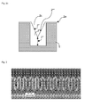
- Bottom-up-filling as shown in fig. 2a can be achieved with the accelerator preferably accumulating and adsorbing on the copper bottom of the trench and thus boosting the copper growth 2'", and with the suppressor adsorbing on the sidewalls of the trench suppressing the copper growth 2".
- the trench filling can proceed with variably shaped copper growth fronts 2"", depicted in figs. 2a to 2c .
- a perfectly working suppressor with complete sidewall coverage and full sidewall growth suppression 2" is shown in fig. 2a . In this case the growth front 2"" is flat with solely growing bottom-up copper 2"'.
- a less effective suppressor results in a copper growth front 2"" depicted in fig. 2b .
- Slight sidewall copper growth 2" with predominant bottom-up copper growth 2'" gives an overall U-shaped growth front 2"".
- a weak suppressor evolves a V-shaped growth front 2"" due to significant sidewall copper growth 2", as depicted in fig. 2c .
- a V-shaped copper growth front 2"" implicates a serious risk of void formation when the trench is filled.
- the U-shaped copper growth front 2" as shown in fig. 2b might provide satisfying trench filling. But since there is an increasing seed overhang issue and/or convex-shaped features with further shrinking feature sizes, as depicted in fig.
- the present invention provides a new class of highly effective, strong suppressing agents that cope with the seed overhang issue and provide defect free trench filling despite a non-conformal copper seed.
- the advantage of the invention is that suppressing agents are provided that result in a extraordinarily pronounced bottom-up fill copper growth while perfectly suppressing the sidewall copper growth, both leading to a flat growth front and thus providing defect free trench fill.
- the strong sidewall copper growth suppression of the invention enables non-conformal copper seeded features and/or convex-shaped features to be substantially void free filled.
- the invention provides an overall homogeneous bottom-up fill in neighboring features of dense feature areas.
- the additives according to the present invention can further advantageously be used for electroplating of copper in through silicon vias (TSV).
- TSV through silicon vias
- Such vias normally have diameters of several micrometers up to 100 micrometers and large aspect ratios of at least 4, sometimes above 10.
- the additives according to the present invention can advantageously be used in bonding technologies such as the manufacture of copper pillars of typically 50 to 100 micrometers height and diameter for the bumping process, in circuit board technologies like the manufacture of high-density-interconnects on printed circuit boards using microvia plating or plated-through-hole technologies, or in other packaging processes for electronic circuits.
- substrates are electroplated by contacting the substrate with the plating baths of the present invention.
- the substrate typically functions as the cathode.
- the plating bath contains an anode, which may be soluble or insoluble.
- cathode and anode may be separated by a membrane.
- Potential is typically applied to the cathode.
- Sufficient current density is applied and plating performed for a period of time sufficient to deposit a metal layer, such as a copper layer, having a desired thickness on the substrate.
- Suitable current densities include, but are not limited to, the range of 1 to 250 mA/cm 2 .
- the current density is in the range of 1 to 60 mA/cm 2 when used to deposit copper in the manufacture of integrated circuits.
- the specific current density depends on the substrate to be plated, the leveling agent selected and the like. Such current density choice is within the abilities of those skilled in the art.
- the applied current may be a direct current (DC), a pulse current (PC), a pulse reverse current (PRC) or other suitable current.
- the plating baths are agitated during use.
- Any suitable agitation method may be used with the present invention and such methods are well-known in the art. Suitable agitation methods include, but are not limited to, inert gas or air sparging, work piece agitation, impingement and the like. Such methods are known to those skilled in the art.
- the wafer may be rotated such as from 1 to 150 RPM and the plating solution contacts the rotating wafer, such as by pumping or spraying. In the alternative, the wafer need not be rotated where the flow of the plating bath is sufficient to provide the desired metal deposit.
- Metal particularly copper is deposited in apertures according to the present invention without substantially forming voids within the metal deposit.
- substantially forming voids it is meant that 95% of the plated apertures are void-free. It is preferred that 98% of the plated apertures are void-free, mostly preferred is that all plated apertures are void-free.
- the present invention may be useful in any electrolytic process where metal filled small features that are substantially free of voids are desired.
- Such processes include printed wiring board manufacture.
- the present plating baths may be useful for the plating of vias, pads or traces on a printed wiring board, as well as for bump plating on wafers.
- Other suitable processes include packaging and interconnect manufacture.
- suitable substrates include lead frames, interconnects, printed wiring boards, and the like.
- Plating equipment for plating semiconductor substrates are well known.
- Plating equipment comprises an electroplating tank which holds Cu electrolyte and which is made of a suitable material such as plastic or other material inert to the electrolytic plating solution.
- the tank may be cylindrical, especially for wafer plating.
- a cathode is horizontally disposed at the upper part of tank and may be any type substrate such as a silicon wafer having openings such as trenches and vias.
- the wafer substrate is typically coated with a seed layer of Cu or other metal or a metal containing layer to initiate plating thereon.
- a Cu seed layer may be applied by chemical vapor deposition (CVD), physical vapor deposition (PVD), or the like.
- An anode is also preferably circular for wafer plating and is horizontally disposed at the lower part of tank forming a space between the anode and cathode.
- the anode is typically a soluble anode.
- the anode may be isolated from the organic bath additives by a membrane.
- the purpose of the separation of the anode and the organic bath additives is to minimize the oxidation of the organic bath additives.
- the cathode substrate and anode are electrically connected by wiring and, respectively, to a rectifier (power supply).
- the cathode substrate for direct or pulse current has a net negative charge so that Cu ions in the solution are reduced at the cathode substrate forming plated Cu metal on the cathode surface.
- An oxidation reaction takes place at the anode.
- the cathode and anode may be horizontally or vertically disposed in the tank.
- Metal particularly copper
- substantially forming voids it is meant that 95% of the plated apertures are void-free. It is preferred that the plated apertures are void-free.
- suitable substrates include lead frames, interconnects, printed wiring boards, and the like.
- the hydroxyl number was determined according to DIN 53240 by heating the sample in pyridine with acetic acid anhydride and acetic acid, followed by titration with potassium hydroxide.
- the molecular weight distribution d was determined by size exclusion chromatography (GPC) with THF as eluent and using PSS SDV columns as solid phase.
- Table 1 Suppressor Starter m of X(OH) m EO number/ PO number per starter (theoretical molecular weight [g/mol]) arrangement Fill quality 1 sorbitol-1 BuO 6 44.3/ 78.4 (6500) PO-EO block + 2 sorbitol 6 44.3/ 78.4 (6500) random + 3 (comparative example) pentaerythritol-3.5 EO 4 44.3/ 78.4 (6500) random - 4 (comparative example) sorbitol 6 44.3/ 78.4 (6500) EO-PO block -
- Sorbitol (182.2 g), an aqueous sodium hydroxide solution (concentration: 50 w% NaOH; 1.8 g) and water (200 ml) were placed into a 2l autoclave and heated at 120 °C under a constant nitrogen flow (0.5 m 3 N 2 / h) for 1 h. Then water was removed at the same temperature in vacuo for 2 h. After nitrogen neutralization butylene oxide (72.1 g) was added in portions at 140°C. To complete the reaction, the mixture was allowed to post-react overnight. Subsequently, propylene oxide (662.0 g) was added in portions at 130 °C and, again, the mixture post-reacted overnight.
- the magnesium silicate Ambosol (27.6 g, CAS No. 93616-22-9), the filtration support Hyflow (1.8 g) and water (20 ml) were added and volatile compounds were removed at the rotary evaporator at 100°C in vacuo. After filtration a highly viscous yellow oil (920.7 g) was obtained as an intermediate product.
- the intermediate product (203.3 g) and aqueous caesium hydroxide solution (concentration: 50 w% CsOH; 2.2 g) were placed into a 2 l autoclave and water was removed at 120 °C in vacuo for 2 h. After nitrogen neutralization additional propylene oxide (863.2 g) was added in portions at 130 °C. To complete the reaction, the mixture was allowed to post-react over weekend. Then, aqueous sodium hydroxide solution (concentration: 50 w% NaOH; 3.0 g) and water (10 ml) were added and water was removed at 120 °C in vacuo for 2 h.
- ethylene oxide 433.5 g was added in portions at 120 °C and the mixture was allowed to post-react overnight.
- Molecular weight distribution d 1.04; OH number 49.4 mg/g KOH.
- Fig. 3 shows the feature sizes of the copper seeded wafer substrate that was used for electroplating with the different plating baths described in the following sections.
- the trenches had a width of 15.6 to 17.9 nanometer at the trench opening, a width of 34.6 to 36.8 nanometer at half height of the trench, and were 176.4 nanometer deep.
- a plating bath was prepared by combining Dl water, 40 g/l copper as copper sulfate, 10 g/l sulfuric acid, 0.050 g/l chloride ion as HCl, 0.028 g/l of SPS and 3.00 ml/l of a 4.5 wt % solution in Dl water of suppressor 1 as prepared in example 1.
- a copper layer was electroplated onto a wafer substrate with feature sizes shown in fig. 3 provided with a copper seed layer by contacting the wafer substrate with the above described plating bath at 25 degrees C applying a direct current of -5 mA/cm 2 for 3 s or 6 s respectively.
- the thus electroplated copper layer was cross-sectioned and investigated by scanning electron micrograph (SEM) inspection.
- Figs. 4a and 4b show the SEM images of the resulting electroplated copper layers.
- Fig. 4a exhibits partially filled trenches after 3 s plating without any voids or seams, and a flat copper growth front in the trenches can be clearly seen indicating the bottom-up filling which is idealized shown in fig. 2a .
- the copper deposition on the sidewalls of the trenches was negligible small showing the strong suppression of the copper growth at the sidewalls of the trenches. All feature openings are still open. After 6 s plating all trenches are completely and defectfree filled exhibiting an overall homogeneous growth front as shown in fig. 4b .
- a plating bath was prepared by combining Dl water, 40 g/l copper as copper sulfate, 10 g/l sulfuric acid, 0.050 g/l chloride ion as HCl, 0.028 g/l of SPS, and 2.00 ml/l of a 5.4 wt % solution in Dl water of suppressor 2 as prepared in example 2.
- a copper layer was electroplated onto a wafer substrate with feature sizes shown in fig. 3 provided with a copper seed layer by contacting the wafer substrate with the above described plating bath at 25 degrees C applying a direct current of -5 mA/cm 2 for 3 s or 6 s respectively.
- the thus electroplated copper layer was cross-sectioned and investigated by SEM inspection.
- Fig. 5a and 5b show the SEM images of the resulting electroplated copper layer.
- 3 s plating as shown in fig. 5a provided partially filled trenches that exhibit a flat copper growth front with very little copper deposition on the sidewalls.
- the suppressing effect of the suppressor used in this example is slightly lower compared to the suppressor applied in example 4 while providing the same filling rate.
- the copper deposition at the trench bottom exceeds the sidewall copper deposition yielding defectfree filled features after 6 s plating as shown in fig. 5b .
- a plating bath was prepared by combining Dl water, 40 g/l copper as copper sulfate, 10 g/l sulfuric acid, 0.050 g/l chloride ion as HCl, 0.028 g/l of SPS, and 3.00 ml/l of a 4.5 wt % solution in Dl water of suppressor 3 as prepared in example 3.
- a copper layer was electroplated onto a wafer substrate with feature sizes shown in fig. 3 provided with a copper seed layer by contacting the wafer substrate with the above described plating bath at 25 degrees C applying a direct current of -5 mA/cm 2 for 3 s or 6 s respectively.
- the thus electroplated copper layer was cross-sectioned and investigated by SEM inspection.
- Fig. 6a and 6b show the SEM images of the resulting electroplated copper layers.
- the plating result after 3 s shown in fig. 6a already clearly indicates that the suppressor candidate used in this example has not sufficient suppressing efficiency to provide voidfree bottom-up filling. Instead, after 3 s plating the trenches are partly filled but with significant copper deposition close to the trench opening thus causing closed trenches with large voids inside.
- the plating result after 6 s provided in fig. 6b confirms the defectivity seen in fig. 6a .
- a mixture of sorbitol (30 g), water (30 g) and aqueous caesium hydroxide solution (concentration: 50 w% CsOH; 1.1 g) and additional water (20 g) were placed into a 21 autoclave and water was removed at 100 °C in vacuo ( ⁇ 10 mbar) for 3h. After nitrogen neutralization ethylene oxide (321.4 g) was added in portions at 130 °C during 16 h until 7 bar. Then, the mixture was cooled to 80 °C and stirred overnight. Subsequently, propylene oxide (750.1 g) was added in portions at 130 °C during 27 h until 7 bar.
- a plating bath was prepared by combining Dl water, 40 g/l copper as copper sulfate, 10 g/l sulfuric acid, 0.050 g/l chloride ion as HCl, 0.028 g/l of SPS, and 2.00 ml/l of a 5.4 wt % solution in Dl water of suppressor 4 as prepared in example 7.
- a copper layer was electroplated onto a wafer substrate with feature sizes shown in fig. 3 provided with a copper seed layer by contacting the wafer substrate with the above described plating bath at 25 degrees C applying a direct current of -5 mA/cm 2 for 3 s or 6 s respectively.
- the thus electroplated copper layer was cross-sectioned and investigated by SEM inspection under a tilt angle of 52°.
- Figs. 7a and 7b show the SEM images of the resulting electroplated copper layer.
- 3 s plating as shown in fig. 7a provided partially filled trenches that exhibit an irregular rough copper growth front with inhomogeneously filled trenches.
- Fig. 7b reveals that after 6 sec plating some trenches are closed while exhibiting pinch-off voids due to insufficient suppressing effect of the applied suppressor at the trench openings.
Description
- Filling of small features, such as vias and trenches, by copper electroplating is an essential part of the semiconductor manufacture process. It is well known, that the presence of organic substances as additives in the electroplating bath can be crucial in achieving a uniform metal deposit on a substrate surface and in avoiding defects, such as voids and seams, within the copper lines.
- One class of additives are the so-called suppressors or suppressing agents. Suppressors are used to provide a substantially bottom-up filling of small features like vias or trenches. The smaller the features are the more sophisticated the additives have to be to avoid voids and seams. In literature, a variety of different suppressing compounds have been described. The mostly used class of suppressors are polyether compounds like polyglycols or polyalkylene oxides like ethylene oxide propylene oxide copolymers.
- Such polyether compounds are manufactured by reacting an alcohol starter comprising one or more hydroxyl groups like glycol or glycerol with polyalkylene oxides.
-
US 2002/0043468 discloses suppressing agents comprising oxygen or nitrogen containing functional groups located in the branches of a polymer backbone. In general, the branched suppressors have a molecular weight in the range of about 10.000 or greater. -
US 2004/0217009 A1 discloses poly(alkylene oxide) random copolymers suppressing agents, which may be linear or star-shaped. -
US 6776893 B1 discloses suppressing agents selected from block copolymers of polyoxyethylene and polyoxypropylene, a polyoxyethylene or polyoxypropylene derivative of a polyhydric alcohol and a mixed polyoxyethylene and polyoxypropylene derivative of a polyhydric alcohol. Examples of polyhydric alcohols are sorbitol, glycerol and mannitol, preferably glycerol. One class of such suppressing agents contain mixed alkoxy groups such as block copolymers of polyethylene oxide and polypropylene oxide. - With further decreasing aperture size of the features like vias or trenches to dimensions of below 100 nanometers and even below 50 nanometers, respectively, the filling of the interconnects with copper becomes especially challenging, also since the copper seed deposition prior to the copper electrodeposition might exhibit inhomogeneity and non-conformality and thus further decreases the aperture sizes particularly at the top of the apertures. Especially apertures with a seed overhang at the top opening or convex-shaped apertures are challenging to fill and require an especially effective copper growth suppression at the side wall of the feature and the opening of the aperture.
-
Fig. 3 shows a seeded substrate exhibiting impact of the seed on the opening of the features to be filled. The seed is shown by the light grey layer on the dark grey structures. Since there is an increasing seed overhang issue with further shrinking feature sizes, as depicted infig. 3 , there is a serious risk of pinch-off void formation in the upper half of the trench close to the opening if the suppressor does not completely avoid sidewall copper growth (2" infig. 2a to 2c ). As can be seen the openings are reduced to less than the half of the width without the seed layer resulting in effective aperture sizes of about 18 nanometer to 16 nanometer, respectively. The seeded feature has a convex shape. - It is therefore an object of the present invention to provide a copper electroplating additive having good superfilling properties, in particular suppressing agents capable of providing a substantially voidless and seamless filling of features on the nanometer and on the micrometer scale with a metal electroplating bath, preferably a copper electroplating bath. It is a further object of the present invention to provide a copper electroplating additive capable of providing a substantially voidless and seamless filling of features having a convex shape.
- Surprisingly, it has now been found, that the use of polyoxyalkylated polyalcohol having random copolymer structure and particular triblock copolymers as additives show extraordinary superfilling properties, particularly if used to fill in features having extremely small aperture sizes and/or high aspect ratios. The present invention provides a new class of highly effective, strongly suppressing agents that cope with the seed overhang issue and provide substantially defect free trench filling despite a non-conformal copper seed.
- Therefore the present invention provides a composition comprising at least one source of metal ions and at least one polyoxyalkylated polyhydric alcohol having at least 5 hydroxyl groups. The at least one suppressing agent is obtainable by reacting a polyhydric alcohol comprising at least 5 hydroxly functional groups with at least a first alkylene oxide and a second alkylene oxide from a mixture of the first alkylene oxide and the second alkylene oxide to form random copolymers of the ethylene oxide and the further C3 to C4 alkylene oxide. In this way a polyhydric alcohol is formed comprising random polyoxyalkylene copolymer side chains.
- The advantage of the additives according to the present invention is their suppressing capability that result in a extraordinarily pronounced bottom-up fill copper growth while perfectly suppressing the sidewall copper growth, both leading to a flat growth front and thus providing substantially defect free trench or via fill. The strong sidewall copper growth suppression of the invention enables non-conformal copper seeded features to be substantially void free filled. Moreover the invention provides an overall homogeneous bottom-up fill in neighboring features of dense feature areas.
- The additives according to the present invention are particularly useful for filling of small features, particularly those having aperture sizes of 30 nanometer or below.
- The additives are generally obtainable by reacting a polyhydric alcohol (also referred to as polyalcohol) comprising at least 5 hydroxyl groups with the alkylene oxides either from a mixture or in sequence. In this way the hydroxyl groups of the polyalcohol are etherified to generate polyoxyalkylene side chains.
- In a preferred composition suitable polyalcohols are represented by formula (I)
X(OH)m (I)
wherein - m
- is an integer from 5 to 10, preferably 5 to 6,
- X
- is an m-valent linear or branched aliphatic or cycloaliphatic radical having from 5 to 10 carbon atoms which may be substituted or unsubstituted.
- It is preferred that the polyalcohol is a linear monosaccharide alcohol represented by formula (II)
HOCH2-(CHOH)n-CH2OH (II)
wherein n is an integer from 3 to 8. Examples of corresponding monosaccharide alcohols (II) comprise sorbitol, mannitol, xylitol, ribitol as well as their stereo isomers, and the like. A particularly preferred monosaccharide alcohol (II) is sorbitol. - It is further preferred that the polyalcohol is a cyclic monosaccharide alcohol represented by formula (III)
(CHOH)o (III)
wherein o is an integer from 5 to 10. Examples of corresponding monosaccharide alcohols (III) comprise inositol (cyclohexanehexole). - In a further composition suitable polyalcohols are monosaccharides and their stereo isomers. Preferred monosaccharides are monosaccharide aldoses of formula (IV)
CHO-(CHOH)p-CH2OH (IV)
wherein p is an integer of 4 to 5. Examples of corresponding monosaccharide aldoses (IV) are allose, altrose, galactose, glucose, gulose, idose, mannose, talose, glucoheptose, mannoheptose and the like. A very preferred monosaccharide aldose (IV) is glucose. - Particularly preferred monosaccharides are monosaccharide ketoses (V)
CH2OH-(CHOH)q-CO-(CHOH)r-CH2OH (V)
wherein q and r are integers and q + r is 3 or 4. Examples of corresponding monosaccharide ketoses (V) are fructose, psicose, sorbose, tagatose, mannoheptulose, sedoheptulose, taloheptulose, alloheptulose and the like. A particularly preferred monosaccharide ketose (V) is fructose and derivatives thereof. - In one embodiment suitable polyalcohols are selected from disaccharides. Particularly preferred disaccharides are sucrose and maltose, and derivatives thereof.
- The additives according to the present invention, further also referred to as polyalkoxylated polyalcohols, are particular reaction products of polyalcohols and alkylene oxides. Polyalkoxylated polyalcohols can be received by reacting the OH groups present in the polyalcohol with alkylene oxides to form terminal polyether groups comprising the respective oxyalkylene units. Polyalkoxylated polyalcohols are per se known in the art.
- Generally, suitable alkylene oxides may be C2- to C12-alkylene oxides or styrene oxide, without being limited thereto. Examples of corresponding alkylene oxides comprise ethylene oxide and propylene oxide, 1-butene oxide, 2,3-butene oxide, 2-methyl-1,2-propene oxide (isobutene oxide), 1-pentene oxide, 2,3-pentene oxide, 2-methyl-1,2-butene oxide, 3-methyl-1,2-butene oxide, 2,3-hexene oxide, 3,4-hexene oxide, 2-methyl-1,2-pentene oxide, 2-ethyl-1,2-butene oxide, 3-methyl-1,2-pentene oxide, decene oxide, 4-methyl-1,2-pentene oxide or styrene oxide.
- Preference is given to using alkylene oxide(s) selected from ethylene oxide, propylene oxide and butylene oxide, or combinations thereof. Preferably the content of ethylene oxide in the copolymer of ethylene oxide and other alkylene oxide(s) is from 10 to 90 % by weight, more preferably from 20 to 50 % by weight, most preferably from 25 to 40 % by weight.
- Preferably the first alkylene oxide is ethylene oxide and the second alkylene oxide is selected from propylene oxide and butylene oxide, or combinations thereof. Most preferably the second alkylene oxide is propylene oxide.
- Preferably, higher alkylene oxides are generally used, at most, in small amounts for fine adjustment of the properties. In general, the amount of ethylene oxide and/or propylene oxide and/ or butylene oxide is at least 80% by weight, preferably at least 90%, most preferably 100% by weight based on the sum of all alkylene oxides used.
- Most preferably the alkylene oxide is selected from mixtures of ethylene oxide and propylene oxide. A preferred weight ratio of oxyethylene and oxypropylene units in the final product is 10:90 to 90:10, more preferred is 20:80 to 50:50, most preferred are 25:75 to 40:60.
- Preferably, the molecular weight Mw of polyalkoxylated polyalcohols is from 500 to 30000 g/mol, more preferred from 1000 to 20000 g/mol, more preferred from 2000 to 15000 g/mol and even more preferred from 3000 to 10000 g/mol. Most preferred is a molecular weight of from 4000 to 8000 g/mol.
- The average degree of polyoxyalkylation is from about 10 to about 500, preferably from about 30 to about 400, more preferably from about 50 to about 300, most preferably from about 60 to about 200 alkylene oxide units per polyalcohol starter.
- The synthesis of polyoxyalkylenes is known to those skilled in the art. Comprehensive details are given, for example, in "Polyoxyalkylenes" in Ullmann's Encyclopedia of Industrial Chemistry, 6th Edition, Electronic Release.
- Preference is given to undertaking the polyoxyalkylation in the presence of a customary basic catalyst, for example alkali metal hydroxides, preferably potassium hydroxide, or alkali metal alkoxides, for example, sodium methoxide or potassium tert-butylate. The polyalkoxylation can be undertaken, in a manner known in principle, in a pressure reactor at from 40 to 250 degree C, preferably from 80 to 200 degree C and more preferably from 100 to 150 degree C. When the melting point of the polyalcohol exceeds the reaction temperature, the polyalcohol is suspended in an inert solvent before the polyalkoxylation reaction. Suitable solvents are toluene, xylenes, polyether and N,N-dimethylformamide.
- The polyalkoxylated polyalcohols may optionally be functionalized in a further reaction step. An additional functionalization can serve to modify the properties of the polyalkoxylated polyalcohols. The terminal hydroxyl groups of the alkoxylated polyalcohols can be reacted with suitable reagents for functionalization, which forms groups of the general formula -(alkoxy)s-Z where Z is any desired group and s is an integer from 1 to 200. According to the functionalizing agent, the chain end can be hydrophobized or more strongly hydrophilized.
- The terminal hydroxyl groups can be esterified, for example, with sulfuric acid or derivatives thereof, so as to form products with terminal sulfate groups (sulfatation). Analogously, products having terminal phosphorus groups can be obtained with phosphoric acid, phosphorous acid, polyphosphoric acid, POCl3 or P4O10 (phosphatation).
- In addition, the terminal OH groups may also be etherified, so as to form ether-terminated polyalkoxy groups of the general formula -(alkoxy)s- Z, where Z is an alkyl, alkenyl, alkynyl, alkaryl, or aryl group and s is an integer from 1 to 200. Preferably, Z is methyl, ethyl, benzyl, acetyl or benzoyl.
- A further embodiment of the present invention is the use of a metal plating bath comprising a composition as described above for depositing the metal on substrates comprising features having an aperture size of 30 nanometers or less.
- A further embodiment of the present invention is a process for depositing a metal layer on a substrate by
- a) contacting a metal plating bath comprising a composition according to the present invention with the substrate, and
- b) applying a current density to the substrate for a time sufficient to deposit a metal layer onto the substrate.
- Preferably the substrate comprises submicrometer sized features and the deposition is performed to fill the submicrometer sized features. Most preferably the submicrometer-sized features have an (effective) aperture size from 1 to 30 nanometers and/or an aspect ratio of 4 or more. More preferably the features have an aperture size of 25 nanometers or below, most preferably of 20 nanometers or below.
- The aperture size according to the present invention means the smallest diameter or free distance of a feature before plating, i.e. after copper seed deposition. The terms "aperture" and "opening" are used herein synonymously. A convex shape is a feature having an aperture size being at least 25 %, preferably 30 %, most preferably 50 % smaller than the biggest diameter or free distance of the feature before plating.
- The plating bath according to the present invention is particular suitable for features having high aspect ratios of 4 or more, particularly of 6 or more.
- A wide variety of metal plating baths may be used with the present invention. Metal electroplating baths typically contain a metal ion source, an electrolyte, and a polymeric suppressing agent.
- The metal ion source may be any compound capable of releasing metal ions to be deposited in the electroplating bath in sufficient amount, i.e. is at least partially soluble in the electroplating bath. It is preferred that the metal ion source is soluble in the plating bath. Suitable metal ion sources are metal salts and include, but are not limited to, metal sulfates, metal halides, metal acetates, metal nitrates, metal fluoroborates, metal alkylsulfonates, metal arylsulfonates, metal sulfamates, metal gluconates and the like. It is preferred that the metal is copper. It is further preferred that the source of metal ions is copper sulfate, copper chloride, copper acetate, copper citrate, copper nitrate, copper fluoroborate, copper methane sulfonate, copper phenyl sulfonate and copper p-toluene sulfonate. Copper sulfate pentahydrate and copper methane sulfonate are particularly preferred. Such metal salts are generally commercially available and may be used without further purification.
- Besides metal electroplating the compositions may be used in electroless deposition of metal containing layers. The compositions may particularly used in the deposition of barrier layers containing Ni, Co, Mo, W and/ or Re. In this case, besides metal ions, further elements of groups III and V, particularly B and P may be present in the composition for electroless deposition und thus co-deposited with the metals.
- The metal ion source may be used in the present invention in any amount that provides sufficient metal ions for electroplating on a substrate. Suitable metal ion sources include, but are not limited to, tin salts, copper salts, and the like. When the metal is copper, the copper salt is typically present in an amount in the range of from about 1 to about 300 g/L of plating solution. It will be appreciated mixtures of metal salts may be electroplated according to the present invention. Thus, alloys, such as copper-tin having up to about 2 percent by weight tin, may be advantageously plated according to the present invention. The amounts of each of the metal salts in such mixtures depend upon the particular alloy to be plated and is well known to those skilled in the art.
- In general, besides the metal ion source and at least one of the suppressing agents according to the present invention the present metal electroplating compositions preferably include electrolyte, i. e. acidic or alkaline electrolyte, one or more sources of metal ions, optionally halide ions, and optionally other additives like accelerators and/or levelers. Such baths are typically aqueous. The water may be present in a wide range of amounts. Any type of water may be used, such as distilled, deionized or tap.
- The electroplating baths of the present invention may be prepared by combining the components in any order. It is preferred that the inorganic components such as metal salts, water, electrolyte and optional halide ion source, are first added to the bath vessel followed by the organic components such as leveling agents, accelerators, suppressors, surfactants and the like.
- Typically, the plating baths of the present invention may be used at any temperature from 10 to 65 degrees C or higher. It is preferred that the temperature of the plating baths is from 10 to 35 degrees C and more preferably from 15 degrees to 30 degrees C.
- Suitable electrolytes include such as, but not limited to, sulfuric acid, acetic acid, fluoroboric acid, alkylsulfonic acids such as methanesulfonic acid, ethanesulfonic acid, propanesulfonic acid and trifluoromethane sulfonic acid, arylsulfonic acids such as phenyl sulfonic acid and toluenesulfonic acid, sulfamic acid, hydrochloric acid, phosphoric acid, tetraalkylammonium hydroxide, preferably tetramethylammonium hydroxide, sodium hydroxide, potassium hydroxide and the like. Acids are typically present in an amount in the range of from about 1 to about 300 g/l, alkaline electrolytes are typically present in an amount of about 0.1 to about 20 g/l or to yield a pH of 8 to 13 respectively, and more typically to yield a pH of 9 to 12.
- Such electrolytes may optionally contain a source of halide ions, such as chloride ions as in copper chloride or hydrochloric acid. A wide range of halide ion concentrations may be used in the present invention such as from about 0 to about 500 ppm. Typically, the halide ion concentration is in the range of from about 10 to about 100 ppm based on the plating bath. It is preferred that the electrolyte is sulfuric acid or methanesulfonic acid, and preferably a mixture of sulfuric acid or methanesulfonic acid and a source of chloride ions. The acids and sources of halide ions useful in the present invention are generally commercially available and may be used without further purification.
- Preferably the composition further comprises at least one accelerating agent and/or at least one leveling agent.
- Any accelerators may be advantageously used in the plating baths according to the present invention. Accelerators useful in the present invention include, but are not limited to, compounds comprising one or more sulphur atom and a sulfonic/phosphonic acid or their salts.
- The generally preferred accelerators have the general structure MO3X-R21-(S)u-R22, with:
- M is a hydrogen or an alkali metal (preferably Na or K)
- X is P or S
- u = 1 to 6
- R21 is selected from C1-C8 alkyl group or heteroalkyl group, an aryl group or a heteroaromatic group. Heteroalkyl groups will have one or more heteroatom (N, S, O) and 1-12 carbon atoms. Carbocyclic aryl groups are typical aryl groups, such as phenyl, naphtyl. Heteroaromatic groups are also suitable aryl groups and contain one or more N,O or S atom and 1-3 separate or fused rings.
- R22 is selected from H or (-S-R21'XO3M), with R21' being identical or different from R21.
- More specifically, useful accelerators include those of the following formulae:
MO3S-R21-SH
MO3S-R21-S-S-R21'-SO3M
MO3S-Ar-S-S-Ar-SO3M
with R21 and R21' are as defined above and Ar is Aryl. - Particularly preferred accelerating agents are:
- SPS: bis-(3-sulfopropyl)-disulfide disodium salt
- MPS: 3-mercapto-1-propansulfonic acid, sodium salt
- Other examples of accelerators, used alone or in mixture, include, but are not limited to: MES (2-Mercaptoethanesulfonic acid, sodium salt); DPS (N,N-dimethyldithiocarbamic acid (3-sulfopropylester), sodium salt); UPS (3-[(amino-iminomethyl)-thio]-1-propylsulfonic acid); ZPS (3-(2-benzthiazolylthio)-1-propanesulfonic acid, sodium salt); 3-mercapto-propylsulfonicacid-(3-sulfopropyl)ester; methyl-(
ω -sulphopropyl)-disulfide, disodium salt; methyl-(ω -sulphopropyl)-trisulfide, disodium salt. - Such accelerators are typically used in an amount of about 0.1 ppm to about 3000 ppm, based on the total weight of the plating bath. Particularly suitable amounts of accelerator useful in the present invention are 1 to 500 ppm, and more particularly 2 to 100 ppm.
- Any additional suppressor may be advantageously used in the present invention. Suppressors useful in the present invention include, but are not limited to, polymeric materials, particularly those having heteroatom substitution, and more particularly oxygen substitution. Suitable suppressors include polyethylene glycol copolymers, particularly polyethylene glycol polypropylene glycol copolymers. The arrangement of ethylene oxide and propylene oxide of suitable suppressors may be block, alternating, gradient, or random. The polyalkylene glycol may comprise further alkylene oxide building blocks such as butylene oxide. Preferably, the average molecular weight of suitable suppressors exceeds about 2000 g/mol. The starting molecules of suitable polyalkylene glycol may be alkyl alcohols such as methanol, ethanol, propanol, n-butanol and the like, aryl alcohols such as phenols and bisphenols, alkaryl alcohols such as benzyl alcohol, polyol starters such as glycol, glycerin, trimethylol propane, pentaerythritol, sorbitol, carbohydrates such as saccharose, and the like, amines and oligoamines such as alkyl amines, aryl amines such as aniline, triethanol amine, ethylene diamine, and the like, amides, lactams, heterocyclic amines such as imidazol and carboxylic acids. Optionally, polyalkylene glycol suppressors may be functionalized by ionic groups such as sulfate, sulfonate, ammonium, and the like.
- When suppressors are used, they are typically present in an amount in the range of from about 1 to about 10,000 ppm based on the weight of the bath, and preferably from about 5 to about 10,000 ppm.
- Leveling agents can advantageously be used in the metal plating baths according to the present invention. The terms "leveling agent" and "leveler" are used herein synonymously.
- Suitable leveling agents include, but are not limited to, one or more of polyethylene imine and derivatives thereof, quaternized polyethylene imine, polyglycine, poly(allylamine), polyaniline, polyurea, polyacrylamide, poly(melamine-co-formaldehyde), reaction products of amines with epichlorohydrin, reaction products of an amine, epichlorohydrin, and polyalkylene oxide, reaction products of an amine with a polyepoxide, polyvinylpyridine, polyvinylimidazole, polyvinylpyrrolidone, or copolymers thereof, nigrosines, pentamethyl-para-rosaniline hydrohalide, hexamethyl-pararosaniline hydrohalide, trialkanolamines and their derivatives or compounds containing a functional group of the formula N-R-S, where R is a substituted alkyl, unsubstituted alkyl, substituted aryl or unsubstituted aryl. Typically, the alkyl groups are (C1-C6)alkyl and preferably (C1-C4)alkyl. In general, the aryl groups include (C6-C20)aryl, preferably (C6-C10)aryl. Such aryl groups may further include heteroatoms, such as sulfur, nitrogen and oxygen. It is preferred that the aryl group is phenyl or napthyl. The compounds containing a functional group of the formula N-R-S are generally known, are generally commercially available and may be used without further purification.
In such compounds containing the N-R-S functional group, the sulfur ("S") and/or the nitrogen ("N") may be attached to such compounds with single or double bonds. When the sulfur is attached to such compounds with a single bond, the sulfur will have another substituent group, such as but not limited to hydrogen, (C1-C12)alkyl, (C2-C12)alkenyl, (C6-C20)aryl, (C1-C12)alkylthio, (C2-C12)alkenylthio, (C6-C20)arylthio and the like. Likewise, the nitrogen will have one or more substituent groups, such as but not limited to hydrogen, (C1-C12)alkyl, (C2-C12)alkenyl, (C7-C10)aryl, and the like. The N-R-S functional group may be acyclic or cyclic. Compounds containing cyclic N-R-S functional groups include those having either the nitrogen or the sulfur or both the nitrogen and the sulfur within the ring system. - By "substituted alkyl" is meant that one or more of the hydrogens on the alkyl group is replaced with another substituent group, such as, but not limited to, cyano, hydroxyl, halo, (C1-C6)alkoxy, (C1-C6)alkylthio, thiol, nitro, and the like. By "substituted aryl" is meant that one or more hydrogens on the aryl ring are replaced with one or more substituent groups, such as, but not limited to, cyano, hydroxyl, halo, (C1-C6)alkoxy, (C1-C6)alkyl, (C2-C6)alkenyl, (C1-C6)alkylthio, thiol, nitro, and the like. "Aryl" includes carbocyclic and heterocyclic aromatic systems, such as, but not limited to, phenyl, naphthyl and the like.
- Polyalkanolamines, alkoxylated polyalkanolamines, functionalized polyalkanolamines, and functionalized alkoxylated polyalkanolamines are particularly preferred levelling agents in copper electroplating baths. Such Polyalkanolamines are described in European patent application No.
08172330.6
Polyalkanolamines can be obtained by condensing at least one trialkanolamine of the general formula N(R11-OH)3 (XIa) and/or at least one dialkanolamine of the general formula R12-N(R11-OH)2 (XIb) to give a polyalkanolamine (XII) (stage A), where the R11 radicals are each independently selected from a divalent, linear and branched aliphatic hydrocarbon radical having from 2 to 6 carbon atoms, and the R12 radicals are each selected from hydrogen and aliphatic, cycloaliphatic and aromatic hydrocarbon radicals, all of which may be linear or branched, having from 1 to 30 carbon atoms. - The alkanolamine can be used as such or may optionally be alkoxylated, functionalized or alkoxylated and functionalized to get alkoxylated polyalkanolamines (XIII), functionalized polyalkanolamines (XIV) or functionalized alkoxylated polyalkanolamines (XV).
- Alkoxylated polyalkanolamines (XIII) can be obtained by alkoxylating polyalkanolamine (XII) with C2- to C12-alkylene oxides, styrene oxide, glycidol, or glycidyl ethers with the proviso that the average degree of alkoxylation is from 0.1 to 200 per OH group and - where present - secondary amino group (stage B).
Functionalized polyalkanolamines (XIV) can be obtained by functionalizing polyalkanolamine (XII) with suitable functionalization reagents which are capable of reaction with hydroxyl groups and/or amino groups (stage C). - Functionalized alkoxylated polyalkanolamines (XV) can be obtained by functionalizing alkoxylated polyalkanolamine (XIII) with suitable functionalization reagents which are capable of reaction with hydroxyl groups and/or amino groups (stage D).
- The trialkanolamines (XIa) and/or dialkanolamines (XIb) used in stage (A) have the general formulae N(R11-OH)3 (XIa) and R12-N(R11-OH)2 (XIb).
- The R11 radicals are in each case independently a divalent linear or branched aliphatic hydrocarbon radical having from 2 to 6 carbon atoms, preferably 2 or 3 carbon atoms. Examples of such radicals comprise ethane-1,2-diyl, propane-1,3-diyl, propane-1,2-diyl, 2-methylpropane-1,2-diyl, 2,2-dimethylpropane-1,3-diyl, butane-1,4-diyl, butane-1,3-diyl (= 1-methylpropane-1,3-diyl), butane-1,2-diyl, butane-2,3-diyl, 2-methylbutane-1,3-diyl, 3-methylbutane-1,3-diyl (= 1,1-dimethylpropane-1,3-diyl), pentane-1,4-diyl, pentane-1,5-diyl, pentane-2,5-diyl, 2-methylpentane-2,5-diyl (= 1,1-dimethylbutane-1,3-diyl) and hexane-1,6-diyl. The radicals are preferably ethane-1,2-diyl, propane-1,3-diyl or propane-1,2-diyl.
- The R12 radical is hydrogen and/or linear or branched aliphatic, cycloaliphatic and/or aromatic hydrocarbon radicals having from 1 to 30 carbon atoms, preferably from 1 to 20 carbon atoms and more preferably from 1 to 10 carbon atoms. Aromatic radicals may of course also have aliphatic substituents. R12 is preferably hydrogen or aliphatic hydrocarbon radicals having from 1 to 4 carbon atoms.
- Examples of preferred trialkanolamines (XIa) comprise triethanolamine, triisopropanolamine and tributan-2-olamine, particular preference is given to triethanolamine.
- Examples of preferred dialkanolamines (XIb) comprise diethanolamine, N-methyldiethanolamine, N,N-bis(2-hydroxypropyl)-N-methylamine, N,N-bis(2-hydroxybutyl)-N-methylamine, N-isopropyldiethanolamine, N-n-butyldiethanolamine, N-sec-butyldiethanolamine, N-cyclohexyldiethanolamine, N-benzyldiethanolamine, N-4-tolyldiethanolamine or N,N-bis(2-hydroxyethyl)aniline. Particular preference is given to diethanolamine.
- In addition to the trialkanolamines (XIa) and/or dialkanolamines (XIb) it is optionally possible to use further components (XIc) having two hydroxyl and/or amino groups for the polycondensation.
- The polycondensation of components (XIa) and/or (XIb) and optionally (XIc) can be carried out by methods known in principle to those skilled in the art while heating the components, with elimination of water. Suitable methods are disclosed, for example, by
EP 441 198 A2 - The condensation is performed typically at temperatures of from 120 to 280 degree C, preferably from 150 to 260 degree C and more preferably from 180 to 240 degree C. The water formed is preferably distilled off. The reaction time is typically from 1 to 16 h, preferably from 2 to 8 h. The degree of condensation can be controlled in a simple manner through the reaction temperature and time.
- The polycondensation is preferably carried out in the presence of an acid, preferably phosphorous acid (H3PO3) and/or hypophosphorous acid (H3PO2). Preferred amounts are from 0.05 to 2% by weight, preferably from 0.1 to 1 % by weight, based on the components to be condensed. In addition to the acid, it is also possible to use additional catalysts, for example, zinc halides or aluminum sulfate, if appropriate in a mixture with acetic acid, as disclosed, for example by
US 4,505,839 . - The viscosity of the resulting polyalkanolamines (XII) is typically in the range from 1000 to 50 000 mPa.s, preferably from 2000 to 20 000 mPa.s and more preferably from 3000 to 13000 mPa.s (each measured on the undiluted product at 20 degree C).
- The mean molar mass Mn (number average) of the resulting polyalkanolamines (XII) is typically in the range from 250 to 50 000 g/mole, preferably from 500 to 40 000 g/mole, more preferably from 1000 to 20 000 g/mole and most preferably from 1000 to 7500 g/mole.
- The mean molar mass Mw (weight average) of the resulting polyalkanolamines (XII) is typically in the range from 250 to 50 000 g/mole, preferably from 500 to 30 000 g/mole, more preferably from 1000 to 20 000 g/mole.
- The resulting polyalkanolamine (XII) preferably has a polydispersity (Mw/Mn) in the range of 1 to 10, and in particular in the range of 1 to 5.
- The polyalkanolamines (XII) can optionally be alkoxylated in a second stage (B). In this step, the OH groups and any secondary amino groups present react with alkylene oxides to form terminal polyether groups.
- Polyalkanolamines (XII) can optionally be functionalized in a further reaction step (C). An additional functionalization can serve to modify the properties of the polyalkanolamines (XII). To this end, the hydroxyl groups and/or amino groups present in the polyalkanolamines (XII) are converted by means of suitable agents which are capable of reaction with hydroxyl groups and/or amino groups. This forms functionalized polyalkanolamines (XIV).
- The alkoxylated polyalkanolamines (XIII) can optionally be functionalized in a further reaction step (D). An additional functionalization can serve to modify the properties of the alkoxylated polyalkanolamines (XIII). To this end, the hydroxyl groups and/or amino groups present in the alkoxylated polyalkanolamines (XIII) are converted by means of suitable agents which are capable of reaction with hydroxyl groups and/or amino groups. This forms functionalized alkoxylated polyalkanolamines (XV).
- In general, the total amount of leveling agents in the electroplating bath is from 0.5 ppm to 10000 ppm based on the total weight of the plating bath. The leveling agents according to the present invention are typically used in a total amount of from about 0.1 ppm to about 1000 ppm based on the total weight of the plating bath and more typically from 1 to 100 ppm, although greater or lesser amounts may be used.
The electroplating baths according to the present invention may include one or more optional additives. Such optional additives include, but are not limited to, accelerators, suppressors, surfactants and the like. Such suppressors and accelerators are generally known in the art. It will be clear to one skilled in the art which suppressors and/or accelerators to use and in what amounts. - A large variety of additives may typically be used in the bath to provide desired surface finishes for the Cu plated metal. Usually more than one additive is used with each additive forming a desired function. Advantageously, the electroplating baths may contain one or more of accelerators, levelers, sources of halide ions, grain refiners and mixtures thereof. Most preferably the electroplating bath contains both, an accelerator and a leveler in addition to the suppressor according to the present invention. Other additives may also be suitably used in the present electroplating baths.
- The present invention is useful for depositing a metal layer, particularly a copper layer, on a variety of substrates, particularly those having submicron and variously sized apertures. For example, the present invention is particularly suitable for depositing copper on integrated circuit substrates, such as semiconductor devices, with small diameter vias, trenches or other apertures. In one embodiment, semiconductor devices are plated according to the present invention. Such semiconductor devices include, but are not limited to, wafers used in the manufacture of integrated circuits.
- The general process of copper electrodeposition on semiconductor integrated circuit substrates is described with respect to
figs. 1 and2 without restricting the invention thereto. -
Fig. 1 a shows a dielectric substrate 1 seeded with acopper layer 2a. With reference tofig. 1b a copper layer 2' is deposited onto the dielectric substrate 1 by electrodeposition. Thetrenches 2c of the substrate 1 are filled and an overplating ofcopper 2b, also referred to as "overburden", is generated on top of the whole structured substrate. During the process, after optional annealing, the overburden ofcopper 2b is removed by chemical mechanical planarization (CMP), as depicted infig. 1c . - A key aspect when filling the
trenches 2c of the substrate 1 with copper by electrodeposition is to achieve a copper layer that is free of defects, especially free of voids and seams. This can be realized by initiating the copper growth at the bottom of the trench with the copper growing up to the mouth of the trench while suppressing copper growth at the sidewalls of the trench. This manner of trench filling, the so-called super-filling or bottom-up-filling, depicted infig. 2a , is sought to achieve by adding certain additives to the plating bath: the accelerator and the suppressor. It is a sensitive interplay between these two additives that has to be carefully adjusted to obtain a trench filling free of any defects. - Bottom-up-filling as shown in
fig. 2a can be achieved with the accelerator preferably accumulating and adsorbing on the copper bottom of the trench and thus boosting the copper growth 2'", and with the suppressor adsorbing on the sidewalls of the trench suppressing thecopper growth 2". Depending on the chemical structure of the suppressor and thus on its suppressing ability, the trench filling can proceed with variably shapedcopper growth fronts 2"", depicted infigs. 2a to 2c . A perfectly working suppressor with complete sidewall coverage and fullsidewall growth suppression 2" is shown infig. 2a . In this case thegrowth front 2"" is flat with solely growing bottom-upcopper 2"'. A less effective suppressor results in acopper growth front 2"" depicted infig. 2b . Slightsidewall copper growth 2" with predominant bottom-up copper growth 2'" gives an overallU-shaped growth front 2"". A weak suppressor evolves a V-shapedgrowth front 2"" due to significantsidewall copper growth 2", as depicted infig. 2c . A V-shapedcopper growth front 2"" implicates a serious risk of void formation when the trench is filled. With a perfectly conformal copper seeded trench the U-shapedcopper growth front 2"" as shown infig. 2b might provide satisfying trench filling. But since there is an increasing seed overhang issue and/or convex-shaped features with further shrinking feature sizes, as depicted infig. 3 , there is a serious risk of pinch-off void formation in the upper half of the trench close to the opening if the suppressor does not completely avoidsidewall copper growth 2". The present invention provides a new class of highly effective, strong suppressing agents that cope with the seed overhang issue and provide defect free trench filling despite a non-conformal copper seed. - The advantage of the invention is that suppressing agents are provided that result in a extraordinarily pronounced bottom-up fill copper growth while perfectly suppressing the sidewall copper growth, both leading to a flat growth front and thus providing defect free trench fill. The strong sidewall copper growth suppression of the invention enables non-conformal copper seeded features and/or convex-shaped features to be substantially void free filled. Moreover the invention provides an overall homogeneous bottom-up fill in neighboring features of dense feature areas.
- The additives according to the present invention can further advantageously be used for electroplating of copper in through silicon vias (TSV). Such vias normally have diameters of several micrometers up to 100 micrometers and large aspect ratios of at least 4, sometimes above 10. Furthermore the additives according to the present invention can advantageously be used in bonding technologies such as the manufacture of copper pillars of typically 50 to 100 micrometers height and diameter for the bumping process, in circuit board technologies like the manufacture of high-density-interconnects on printed circuit boards using microvia plating or plated-through-hole technologies, or in other packaging processes for electronic circuits.
- Typically, substrates are electroplated by contacting the substrate with the plating baths of the present invention. The substrate typically functions as the cathode. The plating bath contains an anode, which may be soluble or insoluble. Optionally, cathode and anode may be separated by a membrane. Potential is typically applied to the cathode. Sufficient current density is applied and plating performed for a period of time sufficient to deposit a metal layer, such as a copper layer, having a desired thickness on the substrate. Suitable current densities include, but are not limited to, the range of 1 to 250 mA/cm2. Typically, the current density is in the range of 1 to 60 mA/cm2 when used to deposit copper in the manufacture of integrated circuits. The specific current density depends on the substrate to be plated, the leveling agent selected and the like. Such current density choice is within the abilities of those skilled in the art. The applied current may be a direct current (DC), a pulse current (PC), a pulse reverse current (PRC) or other suitable current.
- In general, when the present invention is used to deposit metal on a substrate such as a wafer used in the manufacture of an integrated circuit, the plating baths are agitated during use. Any suitable agitation method may be used with the present invention and such methods are well-known in the art. Suitable agitation methods include, but are not limited to, inert gas or air sparging, work piece agitation, impingement and the like. Such methods are known to those skilled in the art. When the present invention is used to plate an integrated circuit substrate, such as a wafer, the wafer may be rotated such as from 1 to 150 RPM and the plating solution contacts the rotating wafer, such as by pumping or spraying. In the alternative, the wafer need not be rotated where the flow of the plating bath is sufficient to provide the desired metal deposit.
- Metal, particularly copper, is deposited in apertures according to the present invention without substantially forming voids within the metal deposit. By the term "without substantially forming voids", it is meant that 95% of the plated apertures are void-free.
It is preferred that 98% of the plated apertures are void-free, mostly preferred is that all plated apertures are void-free. - While the process of the present invention has been generally described with reference to semiconductor manufacture, it will be appreciated that the present invention may be useful in any electrolytic process where metal filled small features that are substantially free of voids are desired. Such processes include printed wiring board manufacture. For example, the present plating baths may be useful for the plating of vias, pads or traces on a printed wiring board, as well as for bump plating on wafers. Other suitable processes include packaging and interconnect manufacture. Accordingly, suitable substrates include lead frames, interconnects, printed wiring boards, and the like.
- Plating equipment for plating semiconductor substrates are well known. Plating equipment comprises an electroplating tank which holds Cu electrolyte and which is made of a suitable material such as plastic or other material inert to the electrolytic plating solution. The tank may be cylindrical, especially for wafer plating. A cathode is horizontally disposed at the upper part of tank and may be any type substrate such as a silicon wafer having openings such as trenches and vias. The wafer substrate is typically coated with a seed layer of Cu or other metal or a metal containing layer to initiate plating thereon. A Cu seed layer may be applied by chemical vapor deposition (CVD), physical vapor deposition (PVD), or the like. An anode is also preferably circular for wafer plating and is horizontally disposed at the lower part of tank forming a space between the anode and cathode. The anode is typically a soluble anode.
- These bath additives are useful in combination with membrane technology being developed by various tool manufacturers. In this system, the anode may be isolated from the organic bath additives by a membrane. The purpose of the separation of the anode and the organic bath additives is to minimize the oxidation of the organic bath additives.
- The cathode substrate and anode are electrically connected by wiring and, respectively, to a rectifier (power supply). The cathode substrate for direct or pulse current has a net negative charge so that Cu ions in the solution are reduced at the cathode substrate forming plated Cu metal on the cathode surface. An oxidation reaction takes place at the anode. The cathode and anode may be horizontally or vertically disposed in the tank.
- Metal, particularly copper, is deposited in apertures according to the present invention without substantially forming voids within the metal deposit. By the term "without substantially forming voids", it is meant that 95% of the plated apertures are void-free.
It is preferred that the plated apertures are void-free.
While the process of the present invention has been generally described with reference to semiconductor manufacture, it will be appreciated that the present invention may be useful in any electrolytic process where a substantially void-free copper deposit is desired. Accordingly, suitable substrates include lead frames, interconnects, printed wiring boards, and the like. - All percent, ppm or comparable values refer to the weight with respect to the total weight of the respective composition except where otherwise indicated.
- The following examples shall further illustrate the present invention without restricting the scope of this invention.
- The hydroxyl number was determined according to DIN 53240 by heating the sample in pyridine with acetic acid anhydride and acetic acid, followed by titration with potassium hydroxide.
- The molecular weight distribution d was determined by size exclusion chromatography (GPC) with THF as eluent and using PSS SDV columns as solid phase.
- Three EO-PO copolymers containing a polyalcohol starter have been synthesized by polyalkoxylation of the respective polyalcohol starting molecule. The compositions of suppressors 1-4 are given in Table 1.
Table 1 Suppressor Starter m of X(OH)m EO number/ PO number per starter (theoretical molecular weight [g/mol]) arrangement Fill quality 1 sorbitol-1 BuO 6 44.3/ 78.4 (6500) PO-EO block + 2 sorbitol 6 44.3/ 78.4 (6500) random + 3 (comparative example) pentaerythritol-3.5 EO 4 44.3/ 78.4 (6500) random - 4 (comparative example) sorbitol 6 44.3/ 78.4 (6500) EO-PO block - - Sorbitol (182.2 g), an aqueous sodium hydroxide solution (concentration: 50 w% NaOH; 1.8 g) and water (200 ml) were placed into a 2l autoclave and heated at 120 °C under a constant nitrogen flow (0.5 m3 N2/ h) for 1 h. Then water was removed at the same temperature in vacuo for 2 h. After nitrogen neutralization butylene oxide (72.1 g) was added in portions at 140°C. To complete the reaction, the mixture was allowed to post-react overnight. Subsequently, propylene oxide (662.0 g) was added in portions at 130 °C and, again, the mixture post-reacted overnight. The magnesium silicate Ambosol (27.6 g, CAS No. 93616-22-9), the filtration support Hyflow (1.8 g) and water (20 ml) were added and volatile compounds were removed at the rotary evaporator at 100°C in vacuo. After filtration a highly viscous yellow oil (920.7 g) was obtained as an intermediate product.
- The intermediate product (203.3 g) and aqueous caesium hydroxide solution (concentration: 50 w% CsOH; 2.2 g) were placed into a 2 l autoclave and water was removed at 120 °C in vacuo for 2 h. After nitrogen neutralization additional propylene oxide (863.2 g) was added in portions at 130 °C. To complete the reaction, the mixture was allowed to post-react over weekend. Then, aqueous sodium hydroxide solution (concentration: 50 w% NaOH; 3.0 g) and water (10 ml) were added and water was removed at 120 °C in vacuo for 2 h. After nitrogen neutralization ethylene oxide (433.5 g) was added in portions at 120 °C and the mixture was allowed to post-react overnight. Ambosol (44.7 g), Hyflow (3 g) and water (20 ml) were added and volatile compounds were removed at the rotary evaporator at 100°C in vacuo. After filtration a light yellow liquid (1491 g) was obtained. Molecular weight distribution d = 1.04; OH number 49.4 mg/g KOH.
- A mixture of sorbitol (30 g), water (30 g) and aqueous caesium hydroxide solution (concentration: 50 w% CsOH; 1.1 g) was stirred overnight. Then this mixture and additional water (20 g) were placed into a 2l autoclave and water was removed at 100 °C in vacuo (< 10 mbar) for 3h. After nitrogen neutralization a mixture of ethylene oxide (321.4 g) and propylene oxide (750.1 g) was added in portions at 130 °C for 3 d. After stirring for 1 d, the reaction mixture was stripped with nitrogen and volatile compounds were removed in vacuo.
Suppressor 2 was obtained as a light yellow liquid (1108 g) having a molecular weight distribution d = 1.08. - A mixture of pentaerythritol-3.5 EO (40 g; from Aldrich, CAS: 30599-15-6), water (10 g) and aqueous caesium hydroxide solution (concentration: 50 w% CsOH; 2.0 g) was stirred overnight. Then this mixture and additional water (20 g) were placed into a 21 autoclave and water was removed at 100 °C in vacuo (< 10 mbar) for 2h. After nitrogen neutralization a mixture of ethylene oxide (282.9 g) and propylene oxide (660.4 g) was added in portions at 130 °C for 4 h at the reaction mixture was stirred for additional 10 h. Then, the reaction mixture was stripped with nitrogen and volatile compounds were removed in vacuo. Suppressor 3 was obtained as a yellow liquid (951 g) having a molecular weight distribution d = 1.12.
-
Fig. 3 shows the feature sizes of the copper seeded wafer substrate that was used for electroplating with the different plating baths described in the following sections. After copper seed deposition the trenches had a width of 15.6 to 17.9 nanometer at the trench opening, a width of 34.6 to 36.8 nanometer at half height of the trench, and were 176.4 nanometer deep. - A plating bath was prepared by combining Dl water, 40 g/l copper as copper sulfate, 10 g/l sulfuric acid, 0.050 g/l chloride ion as HCl, 0.028 g/l of SPS and 3.00 ml/l of a 4.5 wt % solution in Dl water of suppressor 1 as prepared in example 1.
- A copper layer was electroplated onto a wafer substrate with feature sizes shown in
fig. 3 provided with a copper seed layer by contacting the wafer substrate with the above described plating bath at 25 degrees C applying a direct current of -5 mA/cm2 for 3 s or 6 s respectively. The thus electroplated copper layer was cross-sectioned and investigated by scanning electron micrograph (SEM) inspection. -
Figs. 4a and 4b show the SEM images of the resulting electroplated copper layers.Fig. 4a exhibits partially filled trenches after 3 s plating without any voids or seams, and a flat copper growth front in the trenches can be clearly seen indicating the bottom-up filling which is idealized shown infig. 2a . The copper deposition on the sidewalls of the trenches was negligible small showing the strong suppression of the copper growth at the sidewalls of the trenches. All feature openings are still open. After 6 s plating all trenches are completely and defectfree filled exhibiting an overall homogeneous growth front as shown infig. 4b . - A plating bath was prepared by combining Dl water, 40 g/l copper as copper sulfate, 10 g/l sulfuric acid, 0.050 g/l chloride ion as HCl, 0.028 g/l of SPS, and 2.00 ml/l of a 5.4 wt % solution in Dl water of
suppressor 2 as prepared in example 2. - A copper layer was electroplated onto a wafer substrate with feature sizes shown in
fig. 3 provided with a copper seed layer by contacting the wafer substrate with the above described plating bath at 25 degrees C applying a direct current of -5 mA/cm2 for 3 s or 6 s respectively. The thus electroplated copper layer was cross-sectioned and investigated by SEM inspection. -
Fig. 5a and 5b show the SEM images of the resulting electroplated copper layer. 3 s plating as shown infig. 5a provided partially filled trenches that exhibit a flat copper growth front with very little copper deposition on the sidewalls. The suppressing effect of the suppressor used in this example is slightly lower compared to the suppressor applied in example 4 while providing the same filling rate. Anyway, the copper deposition at the trench bottom exceeds the sidewall copper deposition yielding defectfree filled features after 6 s plating as shown infig. 5b . - A plating bath was prepared by combining Dl water, 40 g/l copper as copper sulfate, 10 g/l sulfuric acid, 0.050 g/l chloride ion as HCl, 0.028 g/l of SPS, and 3.00 ml/l of a 4.5 wt % solution in Dl water of suppressor 3 as prepared in example 3.
- A copper layer was electroplated onto a wafer substrate with feature sizes shown in
fig. 3 provided with a copper seed layer by contacting the wafer substrate with the above described plating bath at 25 degrees C applying a direct current of -5 mA/cm2 for 3 s or 6 s respectively. The thus electroplated copper layer was cross-sectioned and investigated by SEM inspection. -
Fig. 6a and 6b show the SEM images of the resulting electroplated copper layers. The plating result after 3 s shown infig. 6a already clearly indicates that the suppressor candidate used in this example has not sufficient suppressing efficiency to provide voidfree bottom-up filling. Instead, after 3 s plating the trenches are partly filled but with significant copper deposition close to the trench opening thus causing closed trenches with large voids inside. The plating result after 6 s provided infig. 6b confirms the defectivity seen infig. 6a . - A mixture of sorbitol (30 g), water (30 g) and aqueous caesium hydroxide solution (concentration: 50 w% CsOH; 1.1 g) and additional water (20 g) were placed into a 21 autoclave and water was removed at 100 °C in vacuo (< 10 mbar) for 3h. After nitrogen neutralization ethylene oxide (321.4 g) was added in portions at 130 °C during 16 h until 7 bar. Then, the mixture was cooled to 80 °C and stirred overnight. Subsequently, propylene oxide (750.1 g) was added in portions at 130 °C during 27 h until 7 bar. After additional 5 h the reaction mixture was cooled to 80 °C, the reaction mixture was stripped with nitrogen and volatile compounds were removed in vacuo. After filtration, suppressor 4 was obtained as a light yellow liquid (1102 g) having a molecular weight distribution d = 1.03.
- A plating bath was prepared by combining Dl water, 40 g/l copper as copper sulfate, 10 g/l sulfuric acid, 0.050 g/l chloride ion as HCl, 0.028 g/l of SPS, and 2.00 ml/l of a 5.4 wt % solution in Dl water of suppressor 4 as prepared in example 7.
- A copper layer was electroplated onto a wafer substrate with feature sizes shown in
fig. 3 provided with a copper seed layer by contacting the wafer substrate with the above described plating bath at 25 degrees C applying a direct current of -5 mA/cm2 for 3 s or 6 s respectively. The thus electroplated copper layer was cross-sectioned and investigated by SEM inspection under a tilt angle of 52°. -
Figs. 7a and 7b show the SEM images of the resulting electroplated copper layer. 3 s plating as shown infig. 7a provided partially filled trenches that exhibit an irregular rough copper growth front with inhomogeneously filled trenches.Fig. 7b reveals that after 6 sec plating some trenches are closed while exhibiting pinch-off voids due to insufficient suppressing effect of the applied suppressor at the trench openings.
Claims (15)
- A composition comprising at least one source of copper and at least one additive obtainable by reactinga) a polyhydric alcohol comprising at least 5 hydroxyl functional groups withb) at least a first alkylene oxide and a second alkylene oxide from a mixture of the first alkylene oxide and the second alkylene oxideto form random copolymers of the ethylene oxide and the further C3 to C4 alkylene oxide.
- The composition according to claim 1, wherein the polyhydric alcohol is selected from compounds of formula I
X(OH)m (I)
whereinm is an integer from 5 to 10,X is an m-valent linear or branched aliphatic or cycloaliphatic radical having from 5 to 10 carbon atoms which may be substituted or unsubstituted. - The composition according to anyone of the preceding claims, wherein the polyalcohols are linear or cyclic monosaccharide alcohols represented by formula (II) or (III)
HOCH2-(CHOH)n-CH2OH (II)
(CHOH)o (III)
whereinn is an integer from 3 to 8 ando is an integer form 5 to 10. - The composition according to claim 3, wherein the monosaccharide alcohol is selected from sorbitol, mannitol, xylitol, ribitol and inositol, and derivatives thereof.
- The composition according to anyone of claim 1 or 2, wherein the polyalcohols are monosaccharides of formula (IV) or (V)
CHO-(CHOH)p-CH2OH (IV)
CH2OH-(CHOH)q-CO-(CHOH)r-CH2OH (V)
and derivatives thereof,
whereinp is an integer of 4 to 5, andq, r are integers and q + r is 3 or 4. - The composition according to claim 5, wherein the monosaccharide is selected from the aldoses allose, altrose, galactose, glucose, gulose, idose, mannose, talose, glucoheptose, mannoheptose or the ketoses fructose, psicose, sorbose, tagatose, mannoheptulose, sedoheptulose, taloheptulose, alloheptulose, and derivatives thereof.
- The composition according to anyone of claim 1 to 6, wherein the first alkylene oxide is ethylene oxide and the second alkylene oxide is propylene oxide.
- The composition according to anyone of the preceding claims, wherein the content of the first oxyalkylene units in the additive is from 20 to 50 % by weight, preferably from 25 to 40 % by weight.
- The composition according to anyone of the preceding claims, wherein the molecular weight Mw of the additive is 3000 - 10000 g/mol, preferably from 4000 to 8000 g/mol.
- The composition according to anyone of the preceding claims, further comprising one or more accelerating agents.
- The composition according to anyone of the preceding claims, further comprising one or more leveling agents.
- Use of a metal plating bath comprising a composition according to anyone of the preceding claims for depositing the metal on substrates comprising features having an aperture size of 30 nanometers or less.
- A process for depositing a metal layer on a substrate bya) contacting a metal plating bath comprising a composition according to any of claims 1 to 11 with the substrate, andb) applying a current density to the substrate for a time sufficient to deposit a metal layer onto the substrate.
- The process according to claim 13, wherein the substrate comprises submicrometer sized features and the deposition is performed to fill the micrometer or submicrometer sized features.
- The process according to claim 14, wherein the submicrometer-sized features have an aperture size from 1 to 30 nm and/or an aspect ratio of 4 or more.
Applications Claiming Priority (2)
| Application Number | Priority Date | Filing Date | Title |
|---|---|---|---|
| US22980909P | 2009-07-30 | 2009-07-30 | |
| PCT/EP2010/060375 WO2011012475A1 (en) | 2009-07-30 | 2010-07-19 | Composition for metal plating comprising suppressing agent for void free submicron feature filling |
Publications (2)
| Publication Number | Publication Date |
|---|---|
| EP2459779A1 EP2459779A1 (en) | 2012-06-06 |
| EP2459779B1 true EP2459779B1 (en) | 2015-09-09 |
Family
ID=42733749
Family Applications (1)
| Application Number | Title | Priority Date | Filing Date |
|---|---|---|---|
| EP10734120.8A Active EP2459779B1 (en) | 2009-07-30 | 2010-07-19 | Composition for metal plating comprising suppressing agent for void free submicron feature filling |
Country Status (11)
| Country | Link |
|---|---|
| US (1) | US9617647B2 (en) |
| EP (1) | EP2459779B1 (en) |
| JP (2) | JP5775077B2 (en) |
| KR (1) | KR101738708B1 (en) |
| CN (1) | CN102471910B (en) |
| IL (1) | IL217234A (en) |
| MY (1) | MY160150A (en) |
| RU (1) | RU2539895C2 (en) |
| SG (2) | SG177418A1 (en) |
| TW (1) | TWI515341B (en) |
| WO (1) | WO2011012475A1 (en) |
Families Citing this family (17)
| Publication number | Priority date | Publication date | Assignee | Title |
|---|---|---|---|---|
| RU2013133648A (en) | 2010-12-21 | 2015-01-27 | Басф Се | COMPOSITION FOR ELECTROLYTIC DEPOSITION OF METALS CONTAINING A LEVELING AGENT |
| EP2530102A1 (en) | 2011-06-01 | 2012-12-05 | Basf Se | Additive and composition for metal electroplating comprising an additive for bottom-up filling of though silicon vias |
| JP6062425B2 (en) | 2011-06-01 | 2017-01-18 | ビーエーエスエフ ソシエタス・ヨーロピアBasf Se | Compositions for metal electroplating including additives for bottom-up filling of through-silicon vias and interconnect features |
| US20130133243A1 (en) | 2011-06-28 | 2013-05-30 | Basf Se | Quaternized nitrogen compounds and use thereof as additives in fuels and lubricants |
| RU2015121797A (en) | 2012-11-09 | 2017-01-10 | Басф Се | COMPOSITION FOR ELECTROLYTIC DEPOSITION OF A METAL CONTAINING A LEVELING AGENT |
| ES2681836T3 (en) | 2015-09-10 | 2018-09-17 | Atotech Deutschland Gmbh | Copper plating bath composition |
| CN110100048B (en) * | 2016-12-20 | 2022-06-21 | 巴斯夫欧洲公司 | Composition for metal plating comprising an inhibiting agent for void-free filling |
| CN107604414B (en) * | 2017-08-22 | 2020-03-24 | 珠海市奥美伦精细化工有限公司 | Aluminum and aluminum alloy anodic oxidation high-temperature nickel-free sealing agent |
| WO2019043146A1 (en) | 2017-09-04 | 2019-03-07 | Basf Se | Composition for metal electroplating comprising leveling agent |
| EP3508620B1 (en) * | 2018-01-09 | 2021-05-19 | ATOTECH Deutschland GmbH | Ureylene additive, its use and a preparation method therefor |
| US20220356592A1 (en) | 2019-09-27 | 2022-11-10 | Basf Se | Composition for copper bump electrodeposition comprising a leveling agent |
| WO2021058334A1 (en) | 2019-09-27 | 2021-04-01 | Basf Se | Composition for copper bump electrodeposition comprising a leveling agent |
| CN115335434A (en) | 2020-04-03 | 2022-11-11 | 巴斯夫欧洲公司 | Composition for copper bump electrodeposition comprising polyaminoamide type leveling agent |
| EP3922662A1 (en) | 2020-06-10 | 2021-12-15 | Basf Se | Polyalkanolamine |
| WO2022012932A1 (en) | 2020-07-13 | 2022-01-20 | Basf Se | Composition for copper electroplating on a cobalt seed |
| WO2023052254A1 (en) | 2021-10-01 | 2023-04-06 | Basf Se | Composition for copper electrodeposition comprising a polyaminoamide type leveling agent |
| WO2024008562A1 (en) | 2022-07-07 | 2024-01-11 | Basf Se | Use of a composition comprising a polyaminoamide type compound for copper nanotwin electrodeposition |
Family Cites Families (23)
| Publication number | Priority date | Publication date | Assignee | Title |
|---|---|---|---|---|
| GB602591A (en) * | 1945-02-12 | 1948-05-31 | Du Pont | Improvements in or relating to the electro-deposition of metals |
| GB1221688A (en) * | 1968-03-09 | 1971-02-03 | Geigy Uk Ltd | Tin electroplating bath and process |
| GB2064585B (en) * | 1979-11-19 | 1983-11-09 | Enthone | Acid zinc electro plating solutions and methods utilizing ethoxylated/propoxylated polyhydric alcohols |
| US4505839A (en) | 1981-05-18 | 1985-03-19 | Petrolite Corporation | Polyalkanolamines |
| SU1035097A1 (en) * | 1981-07-20 | 1983-08-15 | Днепропетровский Ордена Трудового Красного Знамени Государственный Университет Им.300-Летия Воссоединения Украины С Россией | Copper plating electrolyte |
| US4430490A (en) * | 1982-08-10 | 1984-02-07 | Ppg Industries, Inc. | Polyether polyols and their method of preparation |
| JPS59182986A (en) * | 1983-04-01 | 1984-10-17 | Keigo Obata | Tin, lead and tin-lead alloy plating bath |
| JPS62182295A (en) * | 1985-08-07 | 1987-08-10 | Daiwa Tokushu Kk | Copper plating bath composition |
| DE4003243A1 (en) | 1990-02-03 | 1991-08-08 | Basf Ag | Use of tri:alkanolamine polyether(s) as demulsifiers in o/w emulsions - obtainable by condensing tri:alkanol:amine(s) in presence of (hypo)phosphorous acid |
| JPH0641581A (en) * | 1992-07-23 | 1994-02-15 | Seiko Epson Corp | Hydrophilic detergent for contact lens |
| JP3244866B2 (en) * | 1993-05-25 | 2002-01-07 | 株式会社大和化成研究所 | Tin-lead alloy plating bath |
| DE60123189T2 (en) | 2000-10-13 | 2007-10-11 | Shipley Co., L.L.C., Marlborough | Germ layer repair and electroplating bath |
| US6776893B1 (en) * | 2000-11-20 | 2004-08-17 | Enthone Inc. | Electroplating chemistry for the CU filling of submicron features of VLSI/ULSI interconnect |
| EP1422320A1 (en) * | 2002-11-21 | 2004-05-26 | Shipley Company, L.L.C. | Copper electroplating bath |
| WO2004050559A1 (en) * | 2002-12-03 | 2004-06-17 | Asahi Kasei Kabushiki Kaisha | Copper oxide ultrafine particle |
| US20050133376A1 (en) | 2003-12-19 | 2005-06-23 | Opaskar Vincent C. | Alkaline zinc-nickel alloy plating compositions, processes and articles therefrom |
| US20050199507A1 (en) * | 2004-03-09 | 2005-09-15 | Taiwan Semiconductor Manufacturing Co., Ltd. | Chemical structures and compositions of ECP additives to reduce pit defects |
| KR20070086724A (en) * | 2004-11-29 | 2007-08-27 | 테크닉, 인크 | Near neutral ph tin electroplating solution |
| US20060213780A1 (en) | 2005-03-24 | 2006-09-28 | Taiwan Semiconductor Manufacturing Co., Ltd. | Electroplating composition and method |
| RU2282682C1 (en) * | 2005-04-28 | 2006-08-27 | Российский химико-технологический университет им. Д.И. Менделеева | Method and electrolyte for copper plating |
| US20070178697A1 (en) * | 2006-02-02 | 2007-08-02 | Enthone Inc. | Copper electrodeposition in microelectronics |
| JP2008266722A (en) * | 2007-04-20 | 2008-11-06 | Ebara Udylite Kk | Additive for pulse copper-plating bath, and pulse copper-plating bath using the same |
| CN102597329B (en) * | 2009-07-30 | 2015-12-16 | 巴斯夫欧洲公司 | Comprise the tight submicrometer structure filling metal plating compositions of inhibitor |
-
2010
- 2010-07-19 CN CN201080033648.9A patent/CN102471910B/en active Active
- 2010-07-19 SG SG2011097185A patent/SG177418A1/en unknown
- 2010-07-19 WO PCT/EP2010/060375 patent/WO2011012475A1/en active Application Filing
- 2010-07-19 EP EP10734120.8A patent/EP2459779B1/en active Active
- 2010-07-19 US US13/384,732 patent/US9617647B2/en active Active
- 2010-07-19 JP JP2012522097A patent/JP5775077B2/en active Active
- 2010-07-19 KR KR1020127001758A patent/KR101738708B1/en active IP Right Grant
- 2010-07-19 SG SG10201404301WA patent/SG10201404301WA/en unknown
- 2010-07-19 RU RU2012107130/02A patent/RU2539895C2/en not_active IP Right Cessation
- 2010-07-19 MY MYPI2012000018A patent/MY160150A/en unknown
- 2010-07-30 TW TW099125505A patent/TWI515341B/en active
-
2011
- 2011-12-27 IL IL217234A patent/IL217234A/en active IP Right Grant
-
2015
- 2015-07-01 JP JP2015132392A patent/JP6117284B2/en active Active
Also Published As
| Publication number | Publication date |
|---|---|
| EP2459779A1 (en) | 2012-06-06 |
| JP2016029210A (en) | 2016-03-03 |
| JP5775077B2 (en) | 2015-09-09 |
| JP2013500395A (en) | 2013-01-07 |
| IL217234A0 (en) | 2012-02-29 |
| WO2011012475A1 (en) | 2011-02-03 |
| TWI515341B (en) | 2016-01-01 |
| KR20120049237A (en) | 2012-05-16 |
| KR101738708B1 (en) | 2017-05-22 |
| RU2539895C2 (en) | 2015-01-27 |
| IL217234A (en) | 2016-05-31 |
| CN102471910B (en) | 2016-01-20 |
| TW201111558A (en) | 2011-04-01 |
| MY160150A (en) | 2017-02-28 |
| RU2012107130A (en) | 2013-09-10 |
| SG10201404301WA (en) | 2014-09-26 |
| JP6117284B2 (en) | 2017-04-19 |
| SG177418A1 (en) | 2012-02-28 |
| US20120118750A1 (en) | 2012-05-17 |
| US9617647B2 (en) | 2017-04-11 |
| CN102471910A (en) | 2012-05-23 |
Similar Documents
| Publication | Publication Date | Title |
|---|---|---|
| EP2459779B1 (en) | Composition for metal plating comprising suppressing agent for void free submicron feature filling | |
| US20200173029A1 (en) | Composition for metal plating comprising suppressing agent for void free submicron feature filling | |
| US20210317582A1 (en) | Composition for metal plating comprising suppressing agent for void free submicron feature filling | |
| EP2459778B1 (en) | Composition for metal plating comprising suppressing agent for void free submicron feature filling | |
| EP2417284B1 (en) | Composition for metal plating comprising suppressing agent for void free submicron feature filling | |
| US9011666B2 (en) | Composition for metal electroplating comprising leveling agent | |
| EP2917265B1 (en) | Composition for metal electroplating comprising leveling agent | |
| US9834677B2 (en) | Composition for metal electroplating comprising leveling agent | |
| WO2010115757A1 (en) | Composition for metal plating comprising suppressing agent for void free submicron feature filling |
Legal Events
| Date | Code | Title | Description |
|---|---|---|---|
| PUAI | Public reference made under article 153(3) epc to a published international application that has entered the european phase |
Free format text: ORIGINAL CODE: 0009012 |
|
| 17P | Request for examination filed |
Effective date: 20120229 |
|
| AK | Designated contracting states |
Kind code of ref document: A1 Designated state(s): AL AT BE BG CH CY CZ DE DK EE ES FI FR GB GR HR HU IE IS IT LI LT LU LV MC MK MT NL NO PL PT RO SE SI SK SM TR |
|
| DAX | Request for extension of the european patent (deleted) | ||
| 17Q | First examination report despatched |
Effective date: 20141008 |
|
| GRAP | Despatch of communication of intention to grant a patent |
Free format text: ORIGINAL CODE: EPIDOSNIGR1 |
|
| RIC1 | Information provided on ipc code assigned before grant |
Ipc: H01L 21/768 20060101ALI20150224BHEP Ipc: H01L 21/288 20060101ALI20150224BHEP Ipc: C25D 3/38 20060101AFI20150224BHEP Ipc: C25D 3/40 20060101ALN20150224BHEP |
|
| INTG | Intention to grant announced |
Effective date: 20150324 |
|
| GRAS | Grant fee paid |
Free format text: ORIGINAL CODE: EPIDOSNIGR3 |
|
| GRAA | (expected) grant |
Free format text: ORIGINAL CODE: 0009210 |
|
| AK | Designated contracting states |
Kind code of ref document: B1 Designated state(s): AL AT BE BG CH CY CZ DE DK EE ES FI FR GB GR HR HU IE IS IT LI LT LU LV MC MK MT NL NO PL PT RO SE SI SK SM TR |
|
| REG | Reference to a national code |
Ref country code: GB Ref legal event code: FG4D |
|
| REG | Reference to a national code |
Ref country code: AT Ref legal event code: REF Ref document number: 748205 Country of ref document: AT Kind code of ref document: T Effective date: 20150915 Ref country code: CH Ref legal event code: EP |
|
| REG | Reference to a national code |
Ref country code: IE Ref legal event code: FG4D |
|
| REG | Reference to a national code |
Ref country code: DE Ref legal event code: R096 Ref document number: 602010027382 Country of ref document: DE |
|
| PG25 | Lapsed in a contracting state [announced via postgrant information from national office to epo] |
Ref country code: NO Free format text: LAPSE BECAUSE OF FAILURE TO SUBMIT A TRANSLATION OF THE DESCRIPTION OR TO PAY THE FEE WITHIN THE PRESCRIBED TIME-LIMIT Effective date: 20151209 Ref country code: FI Free format text: LAPSE BECAUSE OF FAILURE TO SUBMIT A TRANSLATION OF THE DESCRIPTION OR TO PAY THE FEE WITHIN THE PRESCRIBED TIME-LIMIT Effective date: 20150909 Ref country code: GR Free format text: LAPSE BECAUSE OF FAILURE TO SUBMIT A TRANSLATION OF THE DESCRIPTION OR TO PAY THE FEE WITHIN THE PRESCRIBED TIME-LIMIT Effective date: 20151210 Ref country code: LV Free format text: LAPSE BECAUSE OF FAILURE TO SUBMIT A TRANSLATION OF THE DESCRIPTION OR TO PAY THE FEE WITHIN THE PRESCRIBED TIME-LIMIT Effective date: 20150909 Ref country code: LT Free format text: LAPSE BECAUSE OF FAILURE TO SUBMIT A TRANSLATION OF THE DESCRIPTION OR TO PAY THE FEE WITHIN THE PRESCRIBED TIME-LIMIT Effective date: 20150909 |
|
| REG | Reference to a national code |
Ref country code: LT Ref legal event code: MG4D |
|
| REG | Reference to a national code |
Ref country code: AT Ref legal event code: MK05 Ref document number: 748205 Country of ref document: AT Kind code of ref document: T Effective date: 20150909 |
|
| REG | Reference to a national code |
Ref country code: NL Ref legal event code: FP |
|
| PG25 | Lapsed in a contracting state [announced via postgrant information from national office to epo] |
Ref country code: SE Free format text: LAPSE BECAUSE OF FAILURE TO SUBMIT A TRANSLATION OF THE DESCRIPTION OR TO PAY THE FEE WITHIN THE PRESCRIBED TIME-LIMIT Effective date: 20150909 Ref country code: HR Free format text: LAPSE BECAUSE OF FAILURE TO SUBMIT A TRANSLATION OF THE DESCRIPTION OR TO PAY THE FEE WITHIN THE PRESCRIBED TIME-LIMIT Effective date: 20150909 Ref country code: ES Free format text: LAPSE BECAUSE OF FAILURE TO SUBMIT A TRANSLATION OF THE DESCRIPTION OR TO PAY THE FEE WITHIN THE PRESCRIBED TIME-LIMIT Effective date: 20150909 |
|
| PG25 | Lapsed in a contracting state [announced via postgrant information from national office to epo] |
Ref country code: SK Free format text: LAPSE BECAUSE OF FAILURE TO SUBMIT A TRANSLATION OF THE DESCRIPTION OR TO PAY THE FEE WITHIN THE PRESCRIBED TIME-LIMIT Effective date: 20150909 Ref country code: EE Free format text: LAPSE BECAUSE OF FAILURE TO SUBMIT A TRANSLATION OF THE DESCRIPTION OR TO PAY THE FEE WITHIN THE PRESCRIBED TIME-LIMIT Effective date: 20150909 Ref country code: IS Free format text: LAPSE BECAUSE OF FAILURE TO SUBMIT A TRANSLATION OF THE DESCRIPTION OR TO PAY THE FEE WITHIN THE PRESCRIBED TIME-LIMIT Effective date: 20160109 Ref country code: CZ Free format text: LAPSE BECAUSE OF FAILURE TO SUBMIT A TRANSLATION OF THE DESCRIPTION OR TO PAY THE FEE WITHIN THE PRESCRIBED TIME-LIMIT Effective date: 20150909 |
|
| PG25 | Lapsed in a contracting state [announced via postgrant information from national office to epo] |
Ref country code: RO Free format text: LAPSE BECAUSE OF FAILURE TO SUBMIT A TRANSLATION OF THE DESCRIPTION OR TO PAY THE FEE WITHIN THE PRESCRIBED TIME-LIMIT Effective date: 20150909 Ref country code: PL Free format text: LAPSE BECAUSE OF FAILURE TO SUBMIT A TRANSLATION OF THE DESCRIPTION OR TO PAY THE FEE WITHIN THE PRESCRIBED TIME-LIMIT Effective date: 20150909 Ref country code: AT Free format text: LAPSE BECAUSE OF FAILURE TO SUBMIT A TRANSLATION OF THE DESCRIPTION OR TO PAY THE FEE WITHIN THE PRESCRIBED TIME-LIMIT Effective date: 20150909 Ref country code: PT Free format text: LAPSE BECAUSE OF FAILURE TO SUBMIT A TRANSLATION OF THE DESCRIPTION OR TO PAY THE FEE WITHIN THE PRESCRIBED TIME-LIMIT Effective date: 20160111 |
|
| REG | Reference to a national code |
Ref country code: DE Ref legal event code: R097 Ref document number: 602010027382 Country of ref document: DE |
|
| PLBE | No opposition filed within time limit |
Free format text: ORIGINAL CODE: 0009261 |
|
| STAA | Information on the status of an ep patent application or granted ep patent |
Free format text: STATUS: NO OPPOSITION FILED WITHIN TIME LIMIT |
|
| REG | Reference to a national code |
Ref country code: FR Ref legal event code: PLFP Year of fee payment: 7 |
|
| 26N | No opposition filed |
Effective date: 20160610 |
|
| PG25 | Lapsed in a contracting state [announced via postgrant information from national office to epo] |
Ref country code: SI Free format text: LAPSE BECAUSE OF FAILURE TO SUBMIT A TRANSLATION OF THE DESCRIPTION OR TO PAY THE FEE WITHIN THE PRESCRIBED TIME-LIMIT Effective date: 20150909 Ref country code: DK Free format text: LAPSE BECAUSE OF FAILURE TO SUBMIT A TRANSLATION OF THE DESCRIPTION OR TO PAY THE FEE WITHIN THE PRESCRIBED TIME-LIMIT Effective date: 20150909 |
|
| PG25 | Lapsed in a contracting state [announced via postgrant information from national office to epo] |
Ref country code: BE Free format text: LAPSE BECAUSE OF FAILURE TO SUBMIT A TRANSLATION OF THE DESCRIPTION OR TO PAY THE FEE WITHIN THE PRESCRIBED TIME-LIMIT Effective date: 20150909 |
|
| REG | Reference to a national code |
Ref country code: CH Ref legal event code: PL |
|
| PG25 | Lapsed in a contracting state [announced via postgrant information from national office to epo] |
Ref country code: MC Free format text: LAPSE BECAUSE OF FAILURE TO SUBMIT A TRANSLATION OF THE DESCRIPTION OR TO PAY THE FEE WITHIN THE PRESCRIBED TIME-LIMIT Effective date: 20150909 |
|
| PG25 | Lapsed in a contracting state [announced via postgrant information from national office to epo] |
Ref country code: CH Free format text: LAPSE BECAUSE OF NON-PAYMENT OF DUE FEES Effective date: 20160731 Ref country code: LI Free format text: LAPSE BECAUSE OF NON-PAYMENT OF DUE FEES Effective date: 20160731 |
|
| REG | Reference to a national code |
Ref country code: FR Ref legal event code: PLFP Year of fee payment: 8 |
|
| PG25 | Lapsed in a contracting state [announced via postgrant information from national office to epo] |
Ref country code: LU Free format text: LAPSE BECAUSE OF NON-PAYMENT OF DUE FEES Effective date: 20160719 |
|
| PG25 | Lapsed in a contracting state [announced via postgrant information from national office to epo] |
Ref country code: SM Free format text: LAPSE BECAUSE OF FAILURE TO SUBMIT A TRANSLATION OF THE DESCRIPTION OR TO PAY THE FEE WITHIN THE PRESCRIBED TIME-LIMIT Effective date: 20150909 Ref country code: CY Free format text: LAPSE BECAUSE OF FAILURE TO SUBMIT A TRANSLATION OF THE DESCRIPTION OR TO PAY THE FEE WITHIN THE PRESCRIBED TIME-LIMIT Effective date: 20150909 Ref country code: HU Free format text: LAPSE BECAUSE OF FAILURE TO SUBMIT A TRANSLATION OF THE DESCRIPTION OR TO PAY THE FEE WITHIN THE PRESCRIBED TIME-LIMIT; INVALID AB INITIO Effective date: 20100719 |
|
| PG25 | Lapsed in a contracting state [announced via postgrant information from national office to epo] |
Ref country code: MT Free format text: LAPSE BECAUSE OF NON-PAYMENT OF DUE FEES Effective date: 20160731 Ref country code: TR Free format text: LAPSE BECAUSE OF FAILURE TO SUBMIT A TRANSLATION OF THE DESCRIPTION OR TO PAY THE FEE WITHIN THE PRESCRIBED TIME-LIMIT Effective date: 20150909 Ref country code: MK Free format text: LAPSE BECAUSE OF FAILURE TO SUBMIT A TRANSLATION OF THE DESCRIPTION OR TO PAY THE FEE WITHIN THE PRESCRIBED TIME-LIMIT Effective date: 20150909 |
|
| REG | Reference to a national code |
Ref country code: FR Ref legal event code: PLFP Year of fee payment: 9 |
|
| PG25 | Lapsed in a contracting state [announced via postgrant information from national office to epo] |
Ref country code: BG Free format text: LAPSE BECAUSE OF FAILURE TO SUBMIT A TRANSLATION OF THE DESCRIPTION OR TO PAY THE FEE WITHIN THE PRESCRIBED TIME-LIMIT Effective date: 20150909 |
|
| PG25 | Lapsed in a contracting state [announced via postgrant information from national office to epo] |
Ref country code: AL Free format text: LAPSE BECAUSE OF FAILURE TO SUBMIT A TRANSLATION OF THE DESCRIPTION OR TO PAY THE FEE WITHIN THE PRESCRIBED TIME-LIMIT Effective date: 20150909 |
|
| PGFP | Annual fee paid to national office [announced via postgrant information from national office to epo] |
Ref country code: NL Payment date: 20180920 Year of fee payment: 18 |
|
| PGFP | Annual fee paid to national office [announced via postgrant information from national office to epo] |
Ref country code: GB Payment date: 20180731 Year of fee payment: 9 |
|
| GBPC | Gb: european patent ceased through non-payment of renewal fee |
Effective date: 20190719 |
|
| PG25 | Lapsed in a contracting state [announced via postgrant information from national office to epo] |
Ref country code: NL Free format text: LAPSE BECAUSE OF NON-PAYMENT OF DUE FEES Effective date: 20190801 Ref country code: GB Free format text: LAPSE BECAUSE OF NON-PAYMENT OF DUE FEES Effective date: 20190719 |
|
| REG | Reference to a national code |
Ref country code: NL Ref legal event code: MM Effective date: 20190801 |
|
| PGFP | Annual fee paid to national office [announced via postgrant information from national office to epo] |
Ref country code: IT Payment date: 20200721 Year of fee payment: 11 |
|
| PG25 | Lapsed in a contracting state [announced via postgrant information from national office to epo] |
Ref country code: IT Free format text: LAPSE BECAUSE OF NON-PAYMENT OF DUE FEES Effective date: 20210719 |
|
| PGFP | Annual fee paid to national office [announced via postgrant information from national office to epo] |
Ref country code: IE Payment date: 20230718 Year of fee payment: 14 |
|
| PGFP | Annual fee paid to national office [announced via postgrant information from national office to epo] |
Ref country code: FR Payment date: 20230725 Year of fee payment: 14 Ref country code: DE Payment date: 20230726 Year of fee payment: 14 |