EP3553866A1 - Matériau catalyseur pour une pile à combustible ainsi que son procédé de fabrication - Google Patents
Matériau catalyseur pour une pile à combustible ainsi que son procédé de fabrication Download PDFInfo
- Publication number
- EP3553866A1 EP3553866A1 EP18167304.7A EP18167304A EP3553866A1 EP 3553866 A1 EP3553866 A1 EP 3553866A1 EP 18167304 A EP18167304 A EP 18167304A EP 3553866 A1 EP3553866 A1 EP 3553866A1
- Authority
- EP
- European Patent Office
- Prior art keywords
- catalyst material
- catalyst
- fuel cell
- nife
- material according
- Prior art date
- Legal status (The legal status is an assumption and is not a legal conclusion. Google has not performed a legal analysis and makes no representation as to the accuracy of the status listed.)
- Withdrawn
Links
Images


Classifications
-
- H—ELECTRICITY
- H01—ELECTRIC ELEMENTS
- H01M—PROCESSES OR MEANS, e.g. BATTERIES, FOR THE DIRECT CONVERSION OF CHEMICAL ENERGY INTO ELECTRICAL ENERGY
- H01M4/00—Electrodes
- H01M4/86—Inert electrodes with catalytic activity, e.g. for fuel cells
- H01M4/8647—Inert electrodes with catalytic activity, e.g. for fuel cells consisting of more than one material, e.g. consisting of composites
- H01M4/8652—Inert electrodes with catalytic activity, e.g. for fuel cells consisting of more than one material, e.g. consisting of composites as mixture
-
- H—ELECTRICITY
- H01—ELECTRIC ELEMENTS
- H01M—PROCESSES OR MEANS, e.g. BATTERIES, FOR THE DIRECT CONVERSION OF CHEMICAL ENERGY INTO ELECTRICAL ENERGY
- H01M4/00—Electrodes
- H01M4/86—Inert electrodes with catalytic activity, e.g. for fuel cells
- H01M4/90—Selection of catalytic material
- H01M4/9016—Oxides, hydroxides or oxygenated metallic salts
-
- C—CHEMISTRY; METALLURGY
- C25—ELECTROLYTIC OR ELECTROPHORETIC PROCESSES; APPARATUS THEREFOR
- C25B—ELECTROLYTIC OR ELECTROPHORETIC PROCESSES FOR THE PRODUCTION OF COMPOUNDS OR NON-METALS; APPARATUS THEREFOR
- C25B11/00—Electrodes; Manufacture thereof not otherwise provided for
- C25B11/04—Electrodes; Manufacture thereof not otherwise provided for characterised by the material
- C25B11/051—Electrodes formed of electrocatalysts on a substrate or carrier
- C25B11/073—Electrodes formed of electrocatalysts on a substrate or carrier characterised by the electrocatalyst material
- C25B11/091—Electrodes formed of electrocatalysts on a substrate or carrier characterised by the electrocatalyst material consisting of at least one catalytic element and at least one catalytic compound; consisting of two or more catalytic elements or catalytic compounds
-
- C—CHEMISTRY; METALLURGY
- C25—ELECTROLYTIC OR ELECTROPHORETIC PROCESSES; APPARATUS THEREFOR
- C25B—ELECTROLYTIC OR ELECTROPHORETIC PROCESSES FOR THE PRODUCTION OF COMPOUNDS OR NON-METALS; APPARATUS THEREFOR
- C25B9/00—Cells or assemblies of cells; Constructional parts of cells; Assemblies of constructional parts, e.g. electrode-diaphragm assemblies; Process-related cell features
- C25B9/17—Cells comprising dimensionally-stable non-movable electrodes; Assemblies of constructional parts thereof
- C25B9/19—Cells comprising dimensionally-stable non-movable electrodes; Assemblies of constructional parts thereof with diaphragms
- C25B9/23—Cells comprising dimensionally-stable non-movable electrodes; Assemblies of constructional parts thereof with diaphragms comprising ion-exchange membranes in or on which electrode material is embedded
-
- H—ELECTRICITY
- H01—ELECTRIC ELEMENTS
- H01M—PROCESSES OR MEANS, e.g. BATTERIES, FOR THE DIRECT CONVERSION OF CHEMICAL ENERGY INTO ELECTRICAL ENERGY
- H01M4/00—Electrodes
- H01M4/86—Inert electrodes with catalytic activity, e.g. for fuel cells
- H01M4/90—Selection of catalytic material
- H01M4/9041—Metals or alloys
-
- H—ELECTRICITY
- H01—ELECTRIC ELEMENTS
- H01M—PROCESSES OR MEANS, e.g. BATTERIES, FOR THE DIRECT CONVERSION OF CHEMICAL ENERGY INTO ELECTRICAL ENERGY
- H01M4/00—Electrodes
- H01M4/86—Inert electrodes with catalytic activity, e.g. for fuel cells
- H01M4/90—Selection of catalytic material
- H01M4/9075—Catalytic material supported on carriers, e.g. powder carriers
- H01M4/9083—Catalytic material supported on carriers, e.g. powder carriers on carbon or graphite
-
- H—ELECTRICITY
- H01—ELECTRIC ELEMENTS
- H01M—PROCESSES OR MEANS, e.g. BATTERIES, FOR THE DIRECT CONVERSION OF CHEMICAL ENERGY INTO ELECTRICAL ENERGY
- H01M8/00—Fuel cells; Manufacture thereof
- H01M8/18—Regenerative fuel cells, e.g. redox flow batteries or secondary fuel cells
- H01M8/184—Regeneration by electrochemical means
- H01M8/188—Regeneration by electrochemical means by recharging of redox couples containing fluids; Redox flow type batteries
-
- H—ELECTRICITY
- H01—ELECTRIC ELEMENTS
- H01M—PROCESSES OR MEANS, e.g. BATTERIES, FOR THE DIRECT CONVERSION OF CHEMICAL ENERGY INTO ELECTRICAL ENERGY
- H01M8/00—Fuel cells; Manufacture thereof
- H01M8/10—Fuel cells with solid electrolytes
- H01M2008/1095—Fuel cells with polymeric electrolytes
-
- Y—GENERAL TAGGING OF NEW TECHNOLOGICAL DEVELOPMENTS; GENERAL TAGGING OF CROSS-SECTIONAL TECHNOLOGIES SPANNING OVER SEVERAL SECTIONS OF THE IPC; TECHNICAL SUBJECTS COVERED BY FORMER USPC CROSS-REFERENCE ART COLLECTIONS [XRACs] AND DIGESTS
- Y02—TECHNOLOGIES OR APPLICATIONS FOR MITIGATION OR ADAPTATION AGAINST CLIMATE CHANGE
- Y02P—CLIMATE CHANGE MITIGATION TECHNOLOGIES IN THE PRODUCTION OR PROCESSING OF GOODS
- Y02P70/00—Climate change mitigation technologies in the production process for final industrial or consumer products
- Y02P70/50—Manufacturing or production processes characterised by the final manufactured product
Definitions
- the invention relates to a catalyst material for use as an electrode in a regenerative fuel cell or a reversible electrolysis cell with such, and to a method for its production.
- a unitized regenerative fuel cell (URFC), a hybrid of electrolyzer and fuel cell, provides the ability to store energy from renewable energy sources (solar / wind power plants) by electrochemical cleavage of water in the form of molecular hydrogen and If necessary, to convert back into electrical energy. Water is the only by-product of this process. This offers the possibility to store surplus energy produced in an environmentally friendly way and to provide it when needed. This process can significantly reduce the emission of greenhouse gases (GHG) and thus make an important contribution to the energy transition.
- GHG greenhouse gases
- the performance of electrolyzer systems, fuel cells, or modular regenerative fuel cells is highly dependent on the rate (kinetics) of the ongoing electrochemical reactions.
- NiFe compounds which are present as layered double hydroxide (LDH).
- Dresp et al. S. Dresp, F. Luo, R. Schmack, S.de, M. Gliech and P. Strasser, Energy Environ. Sc., 2016, 9, 2020-2024 ) showed that NiFe-LDH is suitable as the OER-active component in a bifunctional two-component catalyst system.
- the named system has shown tremendous loss of activity during electrochemical stress tests, due to the degradation of the ORR-active carbon-based species caused by the high OER potentials. The activity of the OER-active component was not restricted thereby.
- a second sufficiently stable ORR-active component is required in addition to NiFe-LDH, since NiFe-LDH has no sufficient ORR activity.
- Manganese oxides especially perovskite (Mn 2 O 3 ) and cryptomelane-type oxides (MnO 2 ), show ORR activities in alkaline media comparable to commercial Pt / C.
- the disadvantages of these oxides result from the size of the materials combined with a low surface area, as well as a poor electrical conductivity. These disadvantages require modifications of the metal oxide and the use of a suitable conductive, high surface area support material.
- the most common carrier materials are "carbon blacks" such as Vulcan XC-72R, graphene or carbon nanotubes (CNT). Such support materials, however, lead to a significant destabilization of the catalyst material in view of its carbon corrosion, which can occur at potentials relevant to OER.
- the invention is based on the object to avoid the problems of the prior art.
- a catalyst material for an electrode in a fuel cell, an electrolyzer or a metal-air battery is to be provided, which catalyzes both an oxygen-converting reaction, and an oxygen-generating reaction.
- the electrode provided should have a high long-term stability, especially in comparison to conventional electrodes.
- a first aspect of the invention relates to a catalyst material for a regenerative fuel cell or reversible electrolyzer comprising a multi-component system comprising a doped transition metal oxide, a NiFe intercalation compound, and a conductive carbonaceous support material.
- the present invention provides a bifunctional catalyst material capable of equally catalyzing the oxygen reduction reaction (ORR) and the oxygen generation reaction (OER) in modular regenerative fuel cells (URFC), reversible electrolyzers or metal air batteries.
- the material comprises two electrocatalysts, each of which selectively catalyzes one of the oxygen reactions on an oxygen electrode.
- ORR oxygen reduction reaction
- OER oxygen generation reaction
- URFC modular regenerative fuel cells
- the material comprises two electrocatalysts, each of which selectively catalyzes one of the oxygen reactions on an oxygen electrode.
- the additional carrier material improves overall conductivity and increases activity.
- the copper doped manganese oxide selectively catalyzes the reduction of oxygen (ORR), whereas the NiFe intercalation compound selectively catalyzes the oxygenation reaction (OER).
- ORR reduction of oxygen
- OER oxygenation reaction
- the catalyst material of the invention preferably has comparatively large particles and thus small surfaces.
- the manganese oxide preferably forms rod-shaped particles having an average particle size of preferably 100 x 15 x 15 nm
- the NiFe intercalation compound preferably forms small thin platelets having a diameter in the range of 10-500 nm.
- Conventional noble metal based reference catalysts have a diameter of 1 to 1. 5 nm. Thus, both materials are comparably large electrocatalysts.
- NiFe intercalation compounds tend to minimize the active surface area by covering the reactive interface of the catalyst.
- the catalyst material according to the invention has a surprisingly low degradation by catalyst corrosion, in particular a low tendency to carbon corrosion in the support material. This leads to a significantly higher long-term stability of the catalyst material compared to known systems.
- the doped transition metal oxide is a doped with a dopant M manganese oxide.
- Manganese oxide is particularly cost-effective as a base material and shows notable as OR-activities, especially as ⁇ -manganese oxide, for example in the Cryptonmelan type.
- the transition metal oxide of the formula corresponds to M- ⁇ -MnO 2 .
- the dopant M is selected from the group nickel, copper, silver and / or cobalt. This group of dopants proved to be particularly suitable for increasing the activity of the catalyst material in oxygen reduction reactions.
- the dopant is present in a proportion by weight of between 0.1 and 2.5% by weight, based on the manganese oxide. Doping of the transition metal oxide in these regions was found to be particularly advantageous in the above-mentioned group of potential dopants with respect to the activity and stability of the doped transition metal oxide while maximizing the selective catalysis of the oxygen reduction reaction.
- NiFe intercalation compound is present as layered double hydroxides (LDH).
- LDH layered double hydroxides
- LDHs are a class of ionic solids characterized by a layered structure with the generic sequence [AcBZAcB] n .
- c defines layers of metal cations, where A and B represent layers of hydroxide (HO-ions) and Z layers of others an ion and neutral molecules (such as water). Lateral offsets between the layers can lead to longer repetition periods.
- the intercalated anions (Z) are weakly bound and often interchangeable.
- iron and nickel are divalent and trivalent cations which are arranged in a positive layer c between anionic or neutral hydroxide layers. This is a hydrotalcite-type intercalation compound.
- nickel and iron are present in the molar ratio of 3: 1 to 5: 1 in the NiFe intercalation compound.
- the proportions given are based on molar fractions measured via ICP-OES. However, since the molar masses are very similar, the differences to the proportions by weight are small.
- the conductive carrier material is selected from particulate carbon, so-called carbon black, graphene, nanostructured carbon, carbon nanotubes and / or carbonized carrier material. These materials exhibit optimum electrical conductivities and adjustable surface sizes and are therefore particularly suitable as a support material for the transition metal oxide and / or the intercalation compound.
- the support material serves in particular as a substrate for the transition metal oxide, which is accordingly accumulates on the surface of the carrier material.
- a weight ratio between transition metal oxide, intercalation compound and support material is in the range of 1: 1: 1 to 3: 3: 1.
- the comparatively small active surface already described above, in particular a small free surface of the support material could be generated particularly well in the catalyst material according to the invention with the resulting unexpected advantages with regard to long-term stability of the catalyst material when used in an electrode.
- Another aspect of the invention relates to an electrode, in particular an oxygen electrode for a fuel cell, which comprises the catalyst material according to the invention. Furthermore, the invention relates to a fuel cell comprising an ion exchange membrane, which is coated at least on one side with the catalyst material according to the invention.
- the invention relates to a method for producing the catalyst material according to the invention.
- the inventive method comprises preparing a mixture of the doped transition metal oxide, the Interkallationstress and the conductive support material by physical mixing of the starting materials in powder or particulate form, wherein the particles are preferably nanoparticles, that has average particle sizes in the range of 1 to 100 nm.
- the mixture is suspended with the addition of ultrapure water, iso -propanol and optionally a binder.
- the suspension is preferably supported by ultrasound applications.
- the high-purity water has a resistance of at least 17 M ⁇ , preferably 18.2 M ⁇ or more.
- the resulting catalyst ink is applied to a substrate by conventional methods. After the solvents have evaporated, the catalyst material according to the invention with binder remains on the substrate.
- the binder used is preferably a perfluorinated sulfonic acid polymer, in particular Nafion®. In comparison to other binders, these have the advantage that they have ionic properties and thus the conductivity of the catalyst material not decrease. In addition, perfluorinated sulfonic acid polymers are characterized by high operating temperatures compared to other polymers.
- the water is 70-80 wt .-%, iso- propanol with 15-35 wt .-% of binder and 0-5 wt .-%, in particular 2-5 wt .-%, based on the sum of components Water, iso -propanol and binder contained in the suspension. Particularly preferably, they are present in a ratio of 76.8: 20: 3.2 wt .-% before.
- the solvent ratios and ratios between catalyst and binder can be adjusted to a faster coating process as follows.
- the substrate coated with the catalyst material of the invention is preferably used as an electrode, in particular as an oxygen electrode, in a fuel cell, an electrolyzer of a battery or a regenerative fuel cell or reversible electrolyzer.
- ⁇ -MnO 2 cryptomelane-manganese oxides
- M- ⁇ -MnO 2 , M Cu, Ni, Ag, Co.
- the crystal structure of the resulting manganese oxide is unaffected by the metal dopants. This leads to the conclusion that the amount of dopants can be drastically increased by the synthesis used.
- part b) of FIG. 1 XRD diffractograms of the individual components of the three-component system and the three-component system are shown.
- FIG. 2 Results of electrochemical RDE measurements in oxygen saturated 0.1 M KOH, at 5 mV s -1 , 1600 rpm and a catalyst loading of 203.72 ⁇ g cm -2 are in FIG. 2 shown.
- M manganese oxides of the cryptomelane type
- M Cu, Ni, Ag, Co.
- Cu- ⁇ -MnO 2 has the most positive potential at -3 mA cm -2 and the highest diffusion limit currents, therefore Cu- ⁇ -MnO 2 can be considered as the most active material among the investigated materials and is used for the further measurement of the present invention Catalyst based.
- FIG. 3 Two diagrams are shown which show a) ORR and b) OER activities of NiFe-LDH, Pt / C-Ir / C, Cu- ⁇ -MnO 2 / Carbon, and physically mixed Cu- ⁇ -MnO 2 / Carbon / NiFeLDH demonstrate. It can be seen from the graph that the transition metal oxide-based system of the present invention outperforms the commercial reference catalyst for ORR and OER activity. The ORR activity of manganese oxide is only slightly affected by the addition of NiFe-LDH, while the OER activity is drastically increased.
- FIG. 4 shows a) ORR and b) OER activities of Cu- ⁇ -MnO 2 / carbon, commercial Pt / C-Ir / C and Cu- ⁇ -MnO 2 / carbon / NiFe-LDH after electrochemical loading.
- the stability of the transition metal catalyst exceeds the stability of the commercial reference noble metal catalyst.
- a simple comparison shows that NiFe-LDH considerably improves the stability of the three-component catalyst according to the invention. While the activity of the NiFe-LDH free Cu- ⁇ -MnO 2 / carbon drastically decreases, the activity of the NiFe-LDH containing system is less affected. Therefore, it is assumed that a shielding effect of NiFe-LDH.
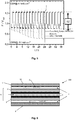
- FIG. 5 Figure 12 is a graph of galvanostatic stability measurements on a rotating disc electrode in an oxygen-saturated 0.1 M KOH solution of the proposed Cu- ⁇ -MnO 2 / Carbon / NiFe-LDH, a reference commercial catalyst, and a transition metal-based comparison system (NiFe-LDH / PANI data Reference).
- the current was held constant at -3 mA cm -2 for the oxygen reduction reaction and constant at 4 mA cm -2 for the oxygen evolution reaction.
- overall activity is stably maintained over more than 18 cycles of alternating OER and ORR potential cycles.
- FIG. 6 A schematic sectional view of a single cell of a total of 100 designated PEM fuel cell is in FIG. 6 to illustrate the structure and its mode of action.
- the fuel cell 100 comprises, as the core component, a membrane-electrode unit 6, which in the present case preferably has an ion exchange membrane 1, and in each case one, adjacent to one of the two flat sides of the membrane 1 electrode 2, namely an anode and a cathode.
- the ion exchange membrane 1 may be a polymer electrolyte membrane, preferably an anion exchange membrane, for example Tokuyama A201, Selemion, Fumasep, which (selectively) permits ion diffusion from the anode space into the cathode space or vice versa.
- the electrodes 2 comprise a catalytic Material that may be supported on an electrically conductive material, such as a carbon-based material.
- Each of the electrodes 2 is followed by a gas diffusion layer 3, which essentially has the task of providing a uniform distribution of the supplied operating gases via the main surfaces of the electrodes 2 or of the membrane 1.
- each bipolar plate 5 On the outer sides of each gas diffusion layer 3, a bipolar plate 5 is arranged. Bipolar plates have the task of electrically interconnecting the individual membrane-electrode units 6 of the individual cells in the stack, to cool the fuel cell stack and to supply the operating gases to the electrodes 2.
- the bipolar plates 5 also called flow field plates
- the flow fields 4 include, for example, a plurality of mutually parallel flow channels, which are incorporated in the form of grooves or grooves in the plates 5.
- each bipolar plate has on its one side an anode flux field which faces the anode 2 and on its other side a cathode flux field facing the cathode. In the present case, only one flow field 4 is shown for each of the two bipolar plates 5 shown.
- the anode flow field is supplied with a fuel, in particular hydrogen (H 2 ), while an oxygen (O 2 ) -containing operating medium, in particular air, is supplied to the cathode flow field.
- a fuel in particular hydrogen (H 2 )
- an oxygen (O 2 ) -containing operating medium in particular air
- the function of the flow fields changes, the anode field becomes the cathode field and vice versa. Therefore, it is more convenient to refer to the electrodes as the oxygen electrode and the hydrogen electrode. In this case, the reactions involving the participation of oxygen, ie the oxygen reduction and the oxygen production reaction, take place at the oxygen electrode. At the hydrogen electrode, on the other hand, the hydrogen generation and hydrogen oxidation reactions take place.
- the catalyst material according to the invention is preferably arranged on the oxygen electrode.
- FIG. 1 The reactions taking place at the electrodes are in FIG. 1 not shown.
- the electrodes catalyzed on the surface of the respective electrode release ions, which then migrate through the membrane 1.
- the oxygen electrode is a catalytic reduction of oxygen O 2 in OH hydroxide ions - taking up electrons instead.
- the hydroxide ions migrate through the anion-conducting membrane 1 and reach the hydrogen electrode.
- the supplied hydrogen H 2 reacts with the hydroxide ions OH - to form water H 2 O, wherein the hydrogen is oxidized and thus emits electrons.
- the electrons of the hydrogen electrode reaction are supplied to the oxygen electrodes via an external circuit, not shown here.
- FIG. 1 It can be seen that the product water of the fuel cell 100 is produced on the oxygen electrode side of the membrane 5.
- the catalytically coated substrate which acts as an electrode comprises a substrate and a catalyst layer applied thereto in accordance with the present invention.
- the catalyst layer may function as an oxygen electrode in a fuel cell.
- the substrate may be a membrane or a gas diffusion layer. In the embodiment shown here, the substrate is a membrane.
- the membrane may in principle be any ion exchange membrane used in fuel cell technology.
- polymer electrolyte membranes whose electrolytic conductivity is based on their moistening with water (eg Nafion®) or those which owe their conductivity to an acid bound to the polymer material or, in the case of an anion exchange membrane, from its quaternary amine, for example doped with trimethylammonium Polysulfone, resulting in quaternary benzyltrimethylammonium groups.
- polymer electrolyte membranes whose electrolytic conductivity is based on their moistening with water (eg Nafion®) or those which owe their conductivity to an acid bound to the polymer material or, in the case of an anion exchange membrane, from its quaternary amine, for example doped with trimethylammonium Polysulfone, resulting in quaternary benzyltrimethylammonium groups.
- the catalyst layer is composed at least of a catalyst material which is arranged on a carrier material. Further, it may comprise a solvent, an electrolyte and / or an electron conductor.
- the carrier material acts as an electron conductor.
- the electron conductor is electrically conductive carbon particles.
- electrically conductive carbon particles it is possible to use all carbon materials known in the field of fuel or electrolysis cells with high electrical conductivity and high surface area.
- the surface is, for example, 50 to 200 m 2 / g.
- carbon blacks, graphite or activated carbons are used. Very particular preference is given to carbon blacks having high conductivity, so-called conductive carbon blacks.
- carbon can also be used in other modifications, for example in granular form or as so-called nanotubes.
- the preferred embodiment of the catalyst material of the invention provides a novel catalyst system which can be used as a bifunctional oxygen electrode in unitized regenerative fuel cells (URFC) and metal air batteries.
- the catalyst system comprises a physical mixture of separately synthesized NiFe-layer double hydroxide (NiFe-LDH), M-doped alpha-MnO 2 (M- ⁇ -MnO 2 ) and additional carbon support.
- the proportion (weight basis) of the dopant in M- ⁇ -MnO 2 is preferably 0.2% by weight, up to 2.2% by weight.
- ⁇ -MnO 2 crystallizes in the cryptomelane structure, which is unaffected by the dopants, such as FIG. 1 shows.
- the carrier material used is preferably commercially available "carbon black", for example Vulcan XC-72R®.
- the component active for the oxidation of water is an intercalation compound, preferably NiFe-LDH.
- the molar ratio between nickel and iron is between 5: 1 and 3: 1.
- the various components are physically mixed by ultrasound.
- a suspension is prepared which contains both electrocatalysts, the carrier material, high-purity water (obtained, for example, by means of Mili-Q), isopropanol and the binder.
- the ratio (weight basis) between Mili-Q, iso -propanol and binder in the case of a slow application to a substrate is preferably 76.8% by weight: 20.0% by weight: 3.2% by weight.
- the total concentration of solids here can be in the range of 3.5 mg L -1 to 5 mg L -1 .
- water and iso-propanol are preferably present at 2% by weight and 98% by weight.
- Solid and binder are then preferably in a ratio of 7: 3 in the solvent mixture.
- the total mass of the solid may be in the range from 15,000 mg L -1 to 22,000 mg L -1 .
- the binder used is a perfluorinated sulfonic acid polymer, such as Nafion® or polysulfone, which contains quaternary benzyltrimethylammonium groups.
- NiFe-LDH is a very active and stable OER catalyst.
- Other transition-metal-based materials capable of catalyzing OER with the same activity as NiFe-LDH are nickel- or vanadium-doped cobalt ferrites (Co x (Ni / V) 3 Fe 2 O 4 ).
- the present electrocatalyst offers several over other bifunctional systems Advantages.
- the mixture of M- ⁇ -MnO 2 , NiFe-LDH, and support material in the preferred composition provides a low cost and competitive electrocatalyst that is simultaneously active for OER and ORR. While the electrochemical cleavage of water is catalyzed by NiFe-LDH, the oxygen reduction is catalyzed by the carbon-supported M- ⁇ -MnO 2 . In each case, the components mentioned are active only for OER or ORR, but not for both reactions.
- ⁇ -MnO 2 was synthesized according to a top-down approach developed by Ding et. al. ( Y. Ding, X. Shen, S. Gomez, R. Kumar, VMB Crisostomo, SL Suib and M. Aindow, Chem. Mater., 2005, 17, 5382-5389 ) has been described.
- To determine the optimal dopant for ⁇ -MnO 2 small amounts of cobalt, copper, silver, nickel and a mixture of cobalt and copper were added to the said synthesis and then tested for ORR activity. The proportion of dopant obtained was between 0.2% by weight (silver) and 2.25% by weight (copper plus cobalt).
- the crystal structure of the catalyst is not influenced by the various dopants ( FIG. 1a )).
- NiFe-LDH The second component, NiFe-LDH, was prepared using a microwave assisted synthesis to dissolve a mixture of Fe (NO) 3 .9H 2 O and Ni (OAc) 2 .4H 2 O in DMF / H 2 O, and according to a regulation by Dresp et. al ( S. Dresp, F. Luo, R. Schmack, S.de, M. Gliech and P. Strasser, Energy Environ. Sc., 2016, 9, 2020-2024 ) has been implemented.
- a three-electrode RDE setup was constructed with a platinum network as the counter electrode, a reversible hydrogen electrode (RHE) as the reference electrode, and a glassy carbon disk coated with the catalyst as the working electrode is used.
- RHE reversible hydrogen electrode
- the copper-doped manganese oxide (Cu- ⁇ -MnO 2 ) is the most active catalyst material in terms of ORR in this series.
- the electrocatalytic activities of the three-component catalyst were determined in the same manner.
- FIG. 3 a) and b) show the electrochemical activities of the three-component catalyst system with respect to ORR and OER.
- the potential difference between -3 mA cm -2 (ORR) and 10 mA cm -2 results in a total overpotential of 0.7086 V ⁇ 0.0011 V.
- the most important achievement of the catalyst material is the long-term stability, which was also evaluated in a three-electrode RDE measurement setup.
- the galvanostatic measurement was carried out at a constant current density of 4mA cm -2 for OER and -3 mA cm -2 for ORR. Between ORR and ORR relevant current density was changed every hour. The results of the stability test are in FIG. 5 shown.
Priority Applications (6)
| Application Number | Priority Date | Filing Date | Title |
|---|---|---|---|
| EP18167304.7A EP3553866A1 (fr) | 2018-04-13 | 2018-04-13 | Matériau catalyseur pour une pile à combustible ainsi que son procédé de fabrication |
| EP19716894.1A EP3776708B1 (fr) | 2018-04-13 | 2019-04-11 | Matériau catalyseur pour une pile à combustible ou électrolyseur ainsi que son procédé de fabrication |
| JP2020554881A JP7149625B2 (ja) | 2018-04-13 | 2019-04-11 | 燃料電池または電気分解装置のための触媒材料、および関連する製造方法 |
| US17/040,942 US11362340B2 (en) | 2018-04-13 | 2019-04-11 | Catalyst material for a fuel cell or an electrolyser and associated production method |
| PCT/EP2019/059197 WO2019197513A1 (fr) | 2018-04-13 | 2019-04-11 | Matériau catalytique pour pile à combustible ou électrolyseur et son procédé de fabrication |
| CN201980025481.2A CN112005414A (zh) | 2018-04-13 | 2019-04-11 | 用于燃料电池或电解槽的催化剂材料以及相关联的生产方法 |
Applications Claiming Priority (1)
| Application Number | Priority Date | Filing Date | Title |
|---|---|---|---|
| EP18167304.7A EP3553866A1 (fr) | 2018-04-13 | 2018-04-13 | Matériau catalyseur pour une pile à combustible ainsi que son procédé de fabrication |
Publications (1)
| Publication Number | Publication Date |
|---|---|
| EP3553866A1 true EP3553866A1 (fr) | 2019-10-16 |
Family
ID=62002003
Family Applications (2)
| Application Number | Title | Priority Date | Filing Date |
|---|---|---|---|
| EP18167304.7A Withdrawn EP3553866A1 (fr) | 2018-04-13 | 2018-04-13 | Matériau catalyseur pour une pile à combustible ainsi que son procédé de fabrication |
| EP19716894.1A Active EP3776708B1 (fr) | 2018-04-13 | 2019-04-11 | Matériau catalyseur pour une pile à combustible ou électrolyseur ainsi que son procédé de fabrication |
Family Applications After (1)
| Application Number | Title | Priority Date | Filing Date |
|---|---|---|---|
| EP19716894.1A Active EP3776708B1 (fr) | 2018-04-13 | 2019-04-11 | Matériau catalyseur pour une pile à combustible ou électrolyseur ainsi que son procédé de fabrication |
Country Status (5)
| Country | Link |
|---|---|
| US (1) | US11362340B2 (fr) |
| EP (2) | EP3553866A1 (fr) |
| JP (1) | JP7149625B2 (fr) |
| CN (1) | CN112005414A (fr) |
| WO (1) | WO2019197513A1 (fr) |
Cited By (2)
| Publication number | Priority date | Publication date | Assignee | Title |
|---|---|---|---|---|
| EP4112781A1 (fr) * | 2021-06-30 | 2023-01-04 | Siemens Energy Global GmbH & Co. KG | Cellule d'électrolyse destinée à l'électrolyse à membrane électrolytique polymère et son procédé de fabrication |
| CN115627493A (zh) * | 2022-12-19 | 2023-01-20 | 清华大学 | 一种铂掺杂催化剂电极及其制备方法和应用 |
Families Citing this family (6)
| Publication number | Priority date | Publication date | Assignee | Title |
|---|---|---|---|---|
| CN110965076A (zh) * | 2019-12-06 | 2020-04-07 | 吉林大学 | 一种双功能三维分层核壳结构电解水电极的制备方法 |
| EP4223416A1 (fr) * | 2020-10-02 | 2023-08-09 | Panasonic Intellectual Property Management Co., Ltd. | Encre de catalyseur d'électrode, catalyseur d'électrode, cellule d'électrolyse de l'eau et dispositif d'électrolyse de l'eau |
| EP4223417A1 (fr) * | 2020-10-02 | 2023-08-09 | Panasonic Intellectual Property Management Co., Ltd. | Encre de catalyseur d'électrode pour cellules d'électrolyse de l'eau, catalyseur d'électrode, cellule d'électrolyse de l'eau et dispositif d'électrolyse de l'eau |
| US11888196B2 (en) | 2021-06-16 | 2024-01-30 | Hydrolite Ltd | Self-refueling power-generating systems |
| CN114068935B (zh) * | 2021-11-15 | 2023-01-24 | 大连理工大学 | 一种高活性Mn/Co-N双位点掺杂碳材料催化剂、制备方法及其在锂硫电池上的应用 |
| CN115650378A (zh) * | 2022-11-01 | 2023-01-31 | 河南师范大学 | 一种MgFe-LDH/AC复合电极材料、电容电极制备方法及应用 |
Family Cites Families (7)
| Publication number | Priority date | Publication date | Assignee | Title |
|---|---|---|---|---|
| JP2005174621A (ja) * | 2003-12-09 | 2005-06-30 | Hitachi Ltd | 燃料電池部材とその製造方法およびそれを用いた燃料電池 |
| JP2008276985A (ja) * | 2007-04-25 | 2008-11-13 | Toshiba Corp | 燃料電池 |
| JP5534831B2 (ja) * | 2010-01-21 | 2014-07-02 | 日本ゴア株式会社 | 固体高分子形燃料電池用ガス拡散層部材および固体高分子形燃料電池 |
| JP5953576B2 (ja) | 2012-03-26 | 2016-07-20 | 国立大学法人北海道大学 | 金属−空気二次電池用空気極触媒層 |
| WO2015146671A1 (fr) * | 2014-03-28 | 2015-10-01 | 日本碍子株式会社 | Électrode à air pour batterie métal-air |
| WO2016006292A1 (fr) * | 2014-07-09 | 2016-01-14 | 日本碍子株式会社 | Électrode à air équipée d'un séparateur pour batterie air-métal |
| CN104505520B (zh) * | 2014-12-06 | 2017-07-04 | 云南冶金集团创能金属燃料电池股份有限公司 | 铝‑空气电池用空气电极及其制备方法 |
-
2018
- 2018-04-13 EP EP18167304.7A patent/EP3553866A1/fr not_active Withdrawn
-
2019
- 2019-04-11 CN CN201980025481.2A patent/CN112005414A/zh active Pending
- 2019-04-11 WO PCT/EP2019/059197 patent/WO2019197513A1/fr active Application Filing
- 2019-04-11 US US17/040,942 patent/US11362340B2/en active Active
- 2019-04-11 EP EP19716894.1A patent/EP3776708B1/fr active Active
- 2019-04-11 JP JP2020554881A patent/JP7149625B2/ja active Active
Non-Patent Citations (5)
| Title |
|---|
| FLEGLER ANDREAS ET AL: "Towards core-shell bifunctional catalyst particles for aqueous metal-air batteries: NiFe-layered double hydroxide nanoparticle coatings on [gamma]-MnO2microparticles", ELECTROCHIMICA ACTA, ELSEVIER SCIENCE PUBLISHERS, BARKING, GB, vol. 231, 4 February 2017 (2017-02-04), pages 216 - 222, XP085134156, ISSN: 0013-4686, DOI: 10.1016/J.ELECTACTA.2017.01.179 * |
| HUANG JINGWEI ET AL: "Mn-doping and NiFe layered double hydroxide coating: Effective approaches to enhancing the performance of [alpha]-Fe2O3in photoelectrochemical water oxidation", JOURNAL OF CATALYSIS, ACADEMIC PRESS, DULUTH, MN, US, vol. 340, 21 June 2016 (2016-06-21), pages 261 - 269, XP029649037, ISSN: 0021-9517, DOI: 10.1016/J.JCAT.2016.05.007 * |
| NING FANYU ET AL: "TiO 2 /graphene/NiFe-layered double hydroxide nanorod array photoanodes for efficient photoelectrochemical water splitting", vol. 9, no. 8, 1 January 2016 (2016-01-01), pages 2633 - 2643, XP009507735, ISSN: 1754-5692, Retrieved from the Internet <URL:http://xlink.rsc.org/?DOI=C6EE01092J> [retrieved on 20160101], DOI: 10.1039/C6EE01092J * |
| S. DRESP; F. LUO; R. SCHMACK; S. KÜHL; M. GLIECH; P. STRASSER, ENERGY ENVIRON. SC., vol. 9, 2016, pages 2020 - 2024 |
| Y. DING; X. SHEN; S. GOMEZ; R. KUMAR; V. M. B. CRISOSTOMO; S. L. SUIB; M. AINDOW, CHEM. MATER., vol. 17, 2005, pages 5382 - 5389 |
Cited By (3)
| Publication number | Priority date | Publication date | Assignee | Title |
|---|---|---|---|---|
| EP4112781A1 (fr) * | 2021-06-30 | 2023-01-04 | Siemens Energy Global GmbH & Co. KG | Cellule d'électrolyse destinée à l'électrolyse à membrane électrolytique polymère et son procédé de fabrication |
| WO2023274601A1 (fr) * | 2021-06-30 | 2023-01-05 | Siemens Energy Global GmbH & Co. KG | Cellule électrolytique pour électrolyse à membrane électrolytique polymère et son procédé de production |
| CN115627493A (zh) * | 2022-12-19 | 2023-01-20 | 清华大学 | 一种铂掺杂催化剂电极及其制备方法和应用 |
Also Published As
| Publication number | Publication date |
|---|---|
| WO2019197513A1 (fr) | 2019-10-17 |
| US11362340B2 (en) | 2022-06-14 |
| JP7149625B2 (ja) | 2022-10-07 |
| EP3776708B1 (fr) | 2022-06-29 |
| CN112005414A (zh) | 2020-11-27 |
| US20210028465A1 (en) | 2021-01-28 |
| EP3776708A1 (fr) | 2021-02-17 |
| JP2021520296A (ja) | 2021-08-19 |
Similar Documents
| Publication | Publication Date | Title |
|---|---|---|
| EP3776708B1 (fr) | Matériau catalyseur pour une pile à combustible ou électrolyseur ainsi que son procédé de fabrication | |
| DE112006001111B4 (de) | Brennstoffzellen | |
| DE112007002953B4 (de) | Brennstoffzelle und Verfahren zum Herstellen eines getragenen Katalysators für eine Brennstoffzelle | |
| DE112006001729B4 (de) | Spannungswechselbeständige Brennstoffzelleneletrokatalysatorschicht, Brennstoffzelle umfassend dieselbe und Verwendung derselben | |
| EP2634850B1 (fr) | Composite, catalyseur comprenant celui-ci, pile à combustible et batterie lithium-air comprenant celui-ci | |
| DE3643332A1 (de) | Elektrokatalysator mit einer platin-kupfer-legierung und eine saeure-elektrolyt-brennstoffzellen-elektrode, die einen solchen katalysator enthaelt | |
| DE112015001452B4 (de) | Sauerstoffreduktionskatalysator und Herstellungsverfahren dafür | |
| DE112006001209T5 (de) | Katalysator für Brennstoffzellenelektrode | |
| DE102007033723B4 (de) | Brennstoffzelle mit einer Opferschicht, um eine Katalysatorträgerkorrosion in einer Brennstoffzellenelektrode zu vermindern | |
| DE112006002630T5 (de) | Brennstoffzellen-Nanokatalysator | |
| DE102015109649A1 (de) | Synthese von Legierungs-Nanopartikeln als stabiler Kern für Kern-Schale-Elektrokatalysatoren | |
| DE112015002354T5 (de) | Membran-elektroden-anordnung | |
| DE112010005461B4 (de) | Brennstoffzelle | |
| DE112011105599T5 (de) | Brennstoffzellen-Katalysatorschicht und deren Verwendungen | |
| DE102011118236A1 (de) | Verbesserte Brennstoffzellen-Lebensdauer durch auf Oxid getragene Edelmetalle in einer Membran | |
| DE112011101133T5 (de) | Brennstoffzelle | |
| DE102012024268A1 (de) | Stabile, haltbare Kohlenstoff geträgerte Katalysatorzusammensetzung für Brennstoffzellen | |
| DE112015001823T5 (de) | Verfahren zur Herstellung eines Brennstoffzellenkatalysators | |
| DE102013211356A1 (de) | Bifunktionale katalysatoren für die elektrokatalytische reduktion von sauerstoff und die oxidation von wasser | |
| EP3479429B1 (fr) | Procédé de fabrication d'un matériau de catalyseur, déposé sur un support, pour une pile à combustible | |
| DE102015101249B4 (de) | Verfahren zur Herstellung eines Elektrokatalysators für eine Elektrode einer elektrochemischen Zelle, elektrochemischer Reaktor und Elektrokatalysator für eine elektrochemische Zelle | |
| EP2160780B1 (fr) | Pile à combustible munie d'un catalyseur et son emploi | |
| KR102580737B1 (ko) | NiCoFe 층상이중수산화물의 제조 방법, NiCoFe 층상이중수산화물, 전극, 막전극접합체 및 이를 포함하는 수전해 시스템 | |
| EP4051637A1 (fr) | Matériau d'électrode, son procédé de production et son utilisation | |
| DE112021004643T5 (de) | Vorrichtung zur elektrolytischen Erzeugung von Wasserstoff |
Legal Events
| Date | Code | Title | Description |
|---|---|---|---|
| PUAI | Public reference made under article 153(3) epc to a published international application that has entered the european phase |
Free format text: ORIGINAL CODE: 0009012 |
|
| AK | Designated contracting states |
Kind code of ref document: A1 Designated state(s): AL AT BE BG CH CY CZ DE DK EE ES FI FR GB GR HR HU IE IS IT LI LT LU LV MC MK MT NL NO PL PT RO RS SE SI SK SM TR |
|
| AX | Request for extension of the european patent |
Extension state: BA ME |
|
| STAA | Information on the status of an ep patent application or granted ep patent |
Free format text: STATUS: THE APPLICATION IS DEEMED TO BE WITHDRAWN |
|
| 18D | Application deemed to be withdrawn |
Effective date: 20200603 |