EP3552057B1 - Dispositifs de diffraction basés sur du cristal liquide cholestérique - Google Patents
Dispositifs de diffraction basés sur du cristal liquide cholestérique Download PDFInfo
- Publication number
- EP3552057B1 EP3552057B1 EP17879066.3A EP17879066A EP3552057B1 EP 3552057 B1 EP3552057 B1 EP 3552057B1 EP 17879066 A EP17879066 A EP 17879066A EP 3552057 B1 EP3552057 B1 EP 3552057B1
- Authority
- EP
- European Patent Office
- Prior art keywords
- light
- clc
- liquid crystal
- layer
- waveguide
- Prior art date
- Legal status (The legal status is an assumption and is not a legal conclusion. Google has not performed a legal analysis and makes no representation as to the accuracy of the status listed.)
- Active
Links
- 239000004986 Cholesteric liquid crystals (ChLC) Substances 0.000 title claims description 273
- 230000003287 optical effect Effects 0.000 claims description 202
- 239000004973 liquid crystal related substance Substances 0.000 claims description 183
- 230000010287 polarization Effects 0.000 claims description 83
- 238000001429 visible spectrum Methods 0.000 claims description 7
- 238000002329 infrared spectrum Methods 0.000 claims description 4
- 239000010410 layer Substances 0.000 claims 2
- 210000001508 eye Anatomy 0.000 description 113
- 239000011295 pitch Substances 0.000 description 76
- 239000000463 material Substances 0.000 description 38
- 150000001875 compounds Chemical class 0.000 description 22
- 238000012545 processing Methods 0.000 description 18
- 238000010168 coupling process Methods 0.000 description 17
- 238000005859 coupling reaction Methods 0.000 description 17
- 238000003384 imaging method Methods 0.000 description 16
- 238000002347 injection Methods 0.000 description 15
- 239000007924 injection Substances 0.000 description 15
- 230000008859 change Effects 0.000 description 12
- 239000003086 colorant Substances 0.000 description 12
- 230000008878 coupling Effects 0.000 description 12
- 239000000835 fiber Substances 0.000 description 11
- 230000001902 propagating effect Effects 0.000 description 11
- 230000003190 augmentative effect Effects 0.000 description 10
- 210000001747 pupil Anatomy 0.000 description 10
- 238000000034 method Methods 0.000 description 8
- 239000000758 substrate Substances 0.000 description 8
- 238000004891 communication Methods 0.000 description 7
- 230000006870 function Effects 0.000 description 7
- 238000006116 polymerization reaction Methods 0.000 description 7
- 239000004990 Smectic liquid crystal Substances 0.000 description 6
- 230000004308 accommodation Effects 0.000 description 6
- 230000003098 cholesteric effect Effects 0.000 description 6
- 230000007423 decrease Effects 0.000 description 6
- 230000003247 decreasing effect Effects 0.000 description 6
- 238000009281 ultraviolet germicidal irradiation Methods 0.000 description 6
- 230000008901 benefit Effects 0.000 description 5
- 238000005516 engineering process Methods 0.000 description 5
- 230000008447 perception Effects 0.000 description 5
- 230000035790 physiological processes and functions Effects 0.000 description 5
- 210000004556 brain Anatomy 0.000 description 4
- 238000005253 cladding Methods 0.000 description 4
- 210000003128 head Anatomy 0.000 description 4
- 239000000178 monomer Substances 0.000 description 4
- 229920000642 polymer Polymers 0.000 description 4
- 230000008569 process Effects 0.000 description 4
- 239000007787 solid Substances 0.000 description 4
- 230000000007 visual effect Effects 0.000 description 4
- 101100126085 Escherichia coli incB gene Proteins 0.000 description 3
- 241000976924 Inca Species 0.000 description 3
- 238000013459 approach Methods 0.000 description 3
- 230000003542 behavioural effect Effects 0.000 description 3
- 230000002996 emotional effect Effects 0.000 description 3
- 230000007613 environmental effect Effects 0.000 description 3
- 210000000720 eyelash Anatomy 0.000 description 3
- 239000011521 glass Substances 0.000 description 3
- 101150001870 incC gene Proteins 0.000 description 3
- 239000007788 liquid Substances 0.000 description 3
- 238000002156 mixing Methods 0.000 description 3
- 239000000203 mixture Substances 0.000 description 3
- 230000002093 peripheral effect Effects 0.000 description 3
- 230000003595 spectral effect Effects 0.000 description 3
- 238000007669 thermal treatment Methods 0.000 description 3
- 238000009826 distribution Methods 0.000 description 2
- 210000000613 ear canal Anatomy 0.000 description 2
- 230000000694 effects Effects 0.000 description 2
- 210000000744 eyelid Anatomy 0.000 description 2
- 230000004438 eyesight Effects 0.000 description 2
- 239000012530 fluid Substances 0.000 description 2
- 101150064356 incD gene Proteins 0.000 description 2
- 238000004519 manufacturing process Methods 0.000 description 2
- 238000005259 measurement Methods 0.000 description 2
- 230000000737 periodic effect Effects 0.000 description 2
- 150000003014 phosphoric acid esters Chemical class 0.000 description 2
- 229920000515 polycarbonate Polymers 0.000 description 2
- 239000004417 polycarbonate Substances 0.000 description 2
- 230000011514 reflex Effects 0.000 description 2
- 210000001525 retina Anatomy 0.000 description 2
- 238000004088 simulation Methods 0.000 description 2
- 238000001228 spectrum Methods 0.000 description 2
- 239000000126 substance Substances 0.000 description 2
- 230000016776 visual perception Effects 0.000 description 2
- TVEXGJYMHHTVKP-UHFFFAOYSA-N 6-oxabicyclo[3.2.1]oct-3-en-7-one Chemical compound C1C2C(=O)OC1C=CC2 TVEXGJYMHHTVKP-UHFFFAOYSA-N 0.000 description 1
- 239000004988 Nematic liquid crystal Substances 0.000 description 1
- 239000004983 Polymer Dispersed Liquid Crystal Substances 0.000 description 1
- XUIMIQQOPSSXEZ-UHFFFAOYSA-N Silicon Chemical compound [Si] XUIMIQQOPSSXEZ-UHFFFAOYSA-N 0.000 description 1
- 241000153282 Theope Species 0.000 description 1
- 239000004974 Thermotropic liquid crystal Substances 0.000 description 1
- 238000010521 absorption reaction Methods 0.000 description 1
- 230000004075 alteration Effects 0.000 description 1
- 230000003416 augmentation Effects 0.000 description 1
- 238000006243 chemical reaction Methods 0.000 description 1
- 239000013626 chemical specie Substances 0.000 description 1
- 239000011248 coating agent Substances 0.000 description 1
- 238000000576 coating method Methods 0.000 description 1
- 230000008867 communication pathway Effects 0.000 description 1
- 210000004087 cornea Anatomy 0.000 description 1
- 238000013500 data storage Methods 0.000 description 1
- 230000001419 dependent effect Effects 0.000 description 1
- 238000001514 detection method Methods 0.000 description 1
- 238000011161 development Methods 0.000 description 1
- 125000004386 diacrylate group Chemical group 0.000 description 1
- 238000009792 diffusion process Methods 0.000 description 1
- 230000008921 facial expression Effects 0.000 description 1
- 239000010408 film Substances 0.000 description 1
- 238000005286 illumination Methods 0.000 description 1
- 230000008676 import Effects 0.000 description 1
- 238000011065 in-situ storage Methods 0.000 description 1
- 230000010354 integration Effects 0.000 description 1
- 230000002452 interceptive effect Effects 0.000 description 1
- 238000002955 isolation Methods 0.000 description 1
- 230000002535 lyotropic effect Effects 0.000 description 1
- 230000006855 networking Effects 0.000 description 1
- 210000001331 nose Anatomy 0.000 description 1
- 239000013307 optical fiber Substances 0.000 description 1
- 238000012856 packing Methods 0.000 description 1
- 230000000704 physical effect Effects 0.000 description 1
- 238000012805 post-processing Methods 0.000 description 1
- 238000007781 pre-processing Methods 0.000 description 1
- 230000000644 propagated effect Effects 0.000 description 1
- 230000004478 pupil constriction Effects 0.000 description 1
- 230000010344 pupil dilation Effects 0.000 description 1
- 230000005855 radiation Effects 0.000 description 1
- 230000029058 respiratory gaseous exchange Effects 0.000 description 1
- 229910052594 sapphire Inorganic materials 0.000 description 1
- 239000010980 sapphire Substances 0.000 description 1
- 229910052710 silicon Inorganic materials 0.000 description 1
- 239000010703 silicon Substances 0.000 description 1
- 125000006850 spacer group Chemical group 0.000 description 1
- 230000003068 static effect Effects 0.000 description 1
- 230000000638 stimulation Effects 0.000 description 1
- 238000003860 storage Methods 0.000 description 1
- 238000006467 substitution reaction Methods 0.000 description 1
- 238000002560 therapeutic procedure Methods 0.000 description 1
- 239000010409 thin film Substances 0.000 description 1
- 230000004470 vergence movement Effects 0.000 description 1
- 230000004304 visual acuity Effects 0.000 description 1
- 238000012800 visualization Methods 0.000 description 1
Images


Classifications
-
- G—PHYSICS
- G02—OPTICS
- G02F—OPTICAL DEVICES OR ARRANGEMENTS FOR THE CONTROL OF LIGHT BY MODIFICATION OF THE OPTICAL PROPERTIES OF THE MEDIA OF THE ELEMENTS INVOLVED THEREIN; NON-LINEAR OPTICS; FREQUENCY-CHANGING OF LIGHT; OPTICAL LOGIC ELEMENTS; OPTICAL ANALOGUE/DIGITAL CONVERTERS
- G02F1/00—Devices or arrangements for the control of the intensity, colour, phase, polarisation or direction of light arriving from an independent light source, e.g. switching, gating or modulating; Non-linear optics
- G02F1/01—Devices or arrangements for the control of the intensity, colour, phase, polarisation or direction of light arriving from an independent light source, e.g. switching, gating or modulating; Non-linear optics for the control of the intensity, phase, polarisation or colour
- G02F1/13—Devices or arrangements for the control of the intensity, colour, phase, polarisation or direction of light arriving from an independent light source, e.g. switching, gating or modulating; Non-linear optics for the control of the intensity, phase, polarisation or colour based on liquid crystals, e.g. single liquid crystal display cells
- G02F1/137—Devices or arrangements for the control of the intensity, colour, phase, polarisation or direction of light arriving from an independent light source, e.g. switching, gating or modulating; Non-linear optics for the control of the intensity, phase, polarisation or colour based on liquid crystals, e.g. single liquid crystal display cells characterised by the electro-optical or magneto-optical effect, e.g. field-induced phase transition, orientation effect, guest-host interaction or dynamic scattering
- G02F1/13718—Devices or arrangements for the control of the intensity, colour, phase, polarisation or direction of light arriving from an independent light source, e.g. switching, gating or modulating; Non-linear optics for the control of the intensity, phase, polarisation or colour based on liquid crystals, e.g. single liquid crystal display cells characterised by the electro-optical or magneto-optical effect, e.g. field-induced phase transition, orientation effect, guest-host interaction or dynamic scattering based on a change of the texture state of a cholesteric liquid crystal
-
- G—PHYSICS
- G02—OPTICS
- G02B—OPTICAL ELEMENTS, SYSTEMS OR APPARATUS
- G02B27/00—Optical systems or apparatus not provided for by any of the groups G02B1/00 - G02B26/00, G02B30/00
- G02B27/0093—Optical systems or apparatus not provided for by any of the groups G02B1/00 - G02B26/00, G02B30/00 with means for monitoring data relating to the user, e.g. head-tracking, eye-tracking
-
- G—PHYSICS
- G02—OPTICS
- G02B—OPTICAL ELEMENTS, SYSTEMS OR APPARATUS
- G02B27/00—Optical systems or apparatus not provided for by any of the groups G02B1/00 - G02B26/00, G02B30/00
- G02B27/01—Head-up displays
- G02B27/017—Head mounted
- G02B27/0172—Head mounted characterised by optical features
-
- G—PHYSICS
- G02—OPTICS
- G02F—OPTICAL DEVICES OR ARRANGEMENTS FOR THE CONTROL OF LIGHT BY MODIFICATION OF THE OPTICAL PROPERTIES OF THE MEDIA OF THE ELEMENTS INVOLVED THEREIN; NON-LINEAR OPTICS; FREQUENCY-CHANGING OF LIGHT; OPTICAL LOGIC ELEMENTS; OPTICAL ANALOGUE/DIGITAL CONVERTERS
- G02F1/00—Devices or arrangements for the control of the intensity, colour, phase, polarisation or direction of light arriving from an independent light source, e.g. switching, gating or modulating; Non-linear optics
- G02F1/01—Devices or arrangements for the control of the intensity, colour, phase, polarisation or direction of light arriving from an independent light source, e.g. switching, gating or modulating; Non-linear optics for the control of the intensity, phase, polarisation or colour
- G02F1/011—Devices or arrangements for the control of the intensity, colour, phase, polarisation or direction of light arriving from an independent light source, e.g. switching, gating or modulating; Non-linear optics for the control of the intensity, phase, polarisation or colour in optical waveguides, not otherwise provided for in this subclass
-
- G—PHYSICS
- G02—OPTICS
- G02F—OPTICAL DEVICES OR ARRANGEMENTS FOR THE CONTROL OF LIGHT BY MODIFICATION OF THE OPTICAL PROPERTIES OF THE MEDIA OF THE ELEMENTS INVOLVED THEREIN; NON-LINEAR OPTICS; FREQUENCY-CHANGING OF LIGHT; OPTICAL LOGIC ELEMENTS; OPTICAL ANALOGUE/DIGITAL CONVERTERS
- G02F1/00—Devices or arrangements for the control of the intensity, colour, phase, polarisation or direction of light arriving from an independent light source, e.g. switching, gating or modulating; Non-linear optics
- G02F1/01—Devices or arrangements for the control of the intensity, colour, phase, polarisation or direction of light arriving from an independent light source, e.g. switching, gating or modulating; Non-linear optics for the control of the intensity, phase, polarisation or colour
- G02F1/13—Devices or arrangements for the control of the intensity, colour, phase, polarisation or direction of light arriving from an independent light source, e.g. switching, gating or modulating; Non-linear optics for the control of the intensity, phase, polarisation or colour based on liquid crystals, e.g. single liquid crystal display cells
- G02F1/133—Constructional arrangements; Operation of liquid crystal cells; Circuit arrangements
- G02F1/1333—Constructional arrangements; Manufacturing methods
- G02F1/1335—Structural association of cells with optical devices, e.g. polarisers or reflectors
- G02F1/133504—Diffusing, scattering, diffracting elements
-
- G—PHYSICS
- G02—OPTICS
- G02F—OPTICAL DEVICES OR ARRANGEMENTS FOR THE CONTROL OF LIGHT BY MODIFICATION OF THE OPTICAL PROPERTIES OF THE MEDIA OF THE ELEMENTS INVOLVED THEREIN; NON-LINEAR OPTICS; FREQUENCY-CHANGING OF LIGHT; OPTICAL LOGIC ELEMENTS; OPTICAL ANALOGUE/DIGITAL CONVERTERS
- G02F1/00—Devices or arrangements for the control of the intensity, colour, phase, polarisation or direction of light arriving from an independent light source, e.g. switching, gating or modulating; Non-linear optics
- G02F1/29—Devices or arrangements for the control of the intensity, colour, phase, polarisation or direction of light arriving from an independent light source, e.g. switching, gating or modulating; Non-linear optics for the control of the position or the direction of light beams, i.e. deflection
- G02F1/292—Devices or arrangements for the control of the intensity, colour, phase, polarisation or direction of light arriving from an independent light source, e.g. switching, gating or modulating; Non-linear optics for the control of the position or the direction of light beams, i.e. deflection by controlled diffraction or phased-array beam steering
-
- G—PHYSICS
- G06—COMPUTING; CALCULATING OR COUNTING
- G06F—ELECTRIC DIGITAL DATA PROCESSING
- G06F3/00—Input arrangements for transferring data to be processed into a form capable of being handled by the computer; Output arrangements for transferring data from processing unit to output unit, e.g. interface arrangements
- G06F3/01—Input arrangements or combined input and output arrangements for interaction between user and computer
- G06F3/03—Arrangements for converting the position or the displacement of a member into a coded form
- G06F3/033—Pointing devices displaced or positioned by the user, e.g. mice, trackballs, pens or joysticks; Accessories therefor
- G06F3/038—Control and interface arrangements therefor, e.g. drivers or device-embedded control circuitry
-
- G—PHYSICS
- G02—OPTICS
- G02B—OPTICAL ELEMENTS, SYSTEMS OR APPARATUS
- G02B27/00—Optical systems or apparatus not provided for by any of the groups G02B1/00 - G02B26/00, G02B30/00
- G02B27/01—Head-up displays
- G02B27/0101—Head-up displays characterised by optical features
- G02B2027/0132—Head-up displays characterised by optical features comprising binocular systems
- G02B2027/0134—Head-up displays characterised by optical features comprising binocular systems of stereoscopic type
-
- G—PHYSICS
- G02—OPTICS
- G02B—OPTICAL ELEMENTS, SYSTEMS OR APPARATUS
- G02B27/00—Optical systems or apparatus not provided for by any of the groups G02B1/00 - G02B26/00, G02B30/00
- G02B27/01—Head-up displays
- G02B27/0179—Display position adjusting means not related to the information to be displayed
- G02B2027/0185—Displaying image at variable distance
-
- G—PHYSICS
- G02—OPTICS
- G02F—OPTICAL DEVICES OR ARRANGEMENTS FOR THE CONTROL OF LIGHT BY MODIFICATION OF THE OPTICAL PROPERTIES OF THE MEDIA OF THE ELEMENTS INVOLVED THEREIN; NON-LINEAR OPTICS; FREQUENCY-CHANGING OF LIGHT; OPTICAL LOGIC ELEMENTS; OPTICAL ANALOGUE/DIGITAL CONVERTERS
- G02F2201/00—Constructional arrangements not provided for in groups G02F1/00 - G02F7/00
- G02F2201/34—Constructional arrangements not provided for in groups G02F1/00 - G02F7/00 reflector
- G02F2201/343—Constructional arrangements not provided for in groups G02F1/00 - G02F7/00 reflector cholesteric liquid crystal reflector
Definitions
- the present disclosure relates to display systems and, more particularly, to augmented reality display systems comprising diffractive devices based on cholesteric liquid crystal.
- a virtual reality, or "VR”, scenario typically involves presentation of digital or virtual image information without transparency to other actual real-world visual input;
- an augmented reality, or "AR”, scenario typically involves presentation of digital or virtual image information as an augmentation to visualization of the actual world around the user.
- a mixed reality, or "MR”, scenario is a type of AR scenario and typically involves virtual objects that are integrated into, and responsive to, the natural world. For example, in an MR scenario, AR image content may be blocked by or otherwise be perceived as interacting with objects in the real world.
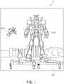
- an augmented reality scene 1 is depicted wherein a user of an AR technology sees a real-world park-like setting 1100 featuring people, trees, buildings in the background, and a concrete platform 1120.
- the user of the AR technology also perceives that he "sees" "virtual content” such as a robot statue 1110 standing upon the real-world platform 1120, and a cartoon-like avatar character 1130 flying by which seems to be a personification of a bumble bee, even though these elements 1130, 1110 do not exist in the real world.
- the human visual perception system is complex, it is challenging to produce an AR technology that facilitates a comfortable, natural-feeling, rich presentation of virtual image elements amongst other virtual or real-world imagery elements.
- aspects of the invention consists of the diffraction grating as defined in claim 1 and the wave-guiding device as defined in claim 8.
- AR systems may display virtual content to a user, or viewer, while still allowing the user to see the world around them.
- this content is displayed on a head-mounted display, e.g., as part of eyewear, that projects image information to the user's eyes.
- the display may also transmit light from the surrounding environment to the user's eyes, to allow a view of that surrounding environment.
- a "head-mounted" display is a display that may be mounted on the head of a viewer.
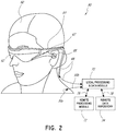
- FIG. 2 illustrates an example of wearable display system 80.
- the display system 80 includes a display 62, and various mechanical and electronic modules and systems to support the functioning of that display 62.
- the display 62 may be coupled to a frame 64, which is wearable by a display system user or viewer 60 and which is configured to position the display 62 in front of the eyes of the user 60.
- the display 62 may be considered eyewear in some embodiments.
- a speaker 66 is coupled to the frame 64 and positioned adjacent the ear canal of the user 60 (in some embodiments, another speaker, not shown, is positioned adjacent the other ear canal of the user to provide for stereo/shapeable sound control).
- the display system may also include one or more microphones 67 or other devices to detect sound.
- the microphone is configured to allow the user to provide inputs or commands to the system 80 (e.g., the selection of voice menu commands, natural language questions, etc.), and/or may allow audio communication with other persons (e.g., with other users of similar display systems
- the microphone may further be configured as a peripheral sensor to continuously collect audio data (e.g., to passively collect from the user and/or environment). Such audio data may include user sounds such as heavy breathing, or environmental sounds, such as a loud bang indicative of a nearby event.
- the display system may also include a peripheral sensor 30a, which may be separate from the frame 64 and attached to the body of the user 60 (e.g., on the head, torso, an extremity, etc. of the user 60).
- the peripheral sensor 30a may be configured to acquire data characterizing the physiological state of the user 60 in some embodiments, as described further herein.
- the sensor 30a may be an electrode.
- the display 62 is operatively coupled by communications link 68, such as by a wired lead or wireless connectivity, to a local data processing module 70 which may be mounted in a variety of configurations, such as fixedly attached to the frame 64, fixedly attached to a helmet or hat worn by the user, embedded in headphones, or otherwise removably attached to the user 60 (e.g., in a backpack-style configuration, in a belt-coupling style configuration).
- the sensor 30a may be operatively coupled by communications link 30b, e.g., a wired lead or wireless connectivity, to the local processor and data module 70.
- the local processing and data module 70 may comprise a hardware processor, as well as digital memory, such as non-volatile memory (e.g., flash memory or hard disk drives), both of which may be utilized to assist in the processing, caching, and storage of data.
- the data include data a) captured from sensors (which may be, e.g., operatively coupled to the frame 64 or otherwise attached to the user 60), such as image capture devices (such as cameras), microphones, inertial measurement units, accelerometers, compasses, GPS units, radio devices, gyros, and/or other sensors disclosed herein; and/or b) acquired and/or processed using remote processing module 72 and/or remote data repository 74 (including data relating to virtual content), possibly for passage to the display 62 after such processing or retrieval.
- sensors which may be, e.g., operatively coupled to the frame 64 or otherwise attached to the user 60
- image capture devices such as cameras
- microphones such as inertial measurement units
- accelerometers compasses
- GPS units
- the local processing and data module 70 may be operatively coupled by communication links 76, 78, such as via a wired or wireless communication links, to the remote processing module 72 and remote data repository 74 such that these remote modules 72, 74 are operatively coupled to each other and available as resources to the local processing and data module 70.
- the local processing and data module 70 may include one or more of the image capture devices, microphones, inertial measurement units, accelerometers, compasses, GPS units, radio devices, and/or gyros. In some other embodiments, one or more of these sensors may be attached to the frame 64, or may be standalone structures that communicate with the local processing and data module 70 by wired or wireless communication pathways.
- the remote processing module 72 may comprise one or more processors configured to analyze and process data and/or image information.
- the remote data repository 74 may comprise a digital data storage facility, which may be available through the internet or other networking configuration in a "cloud" resource configuration.
- the remote data repository 74 may include one or more remote servers, which provide information, e.g., information for generating augmented reality content, to the local processing and data module 70 and/or the remote processing module 72.
- all data is stored and all computations are performed in the local processing and data module, allowing fully autonomous use from a remote module.
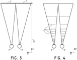
- FIG. 3 illustrates a conventional display system for simulating three-dimensional imagery for a user.
- the images 5, 7 are spaced from the eyes 4, 6 by a distance 10 along an optical or z-axis parallel to the line of sight of the viewer.
- the images 5, 7 are flat and the eyes 4, 6 may focus on the images by assuming a single accommodated state.
- Such systems rely on the human visual system to combine the images 5, 7 to provide a perception of depth and/or scale for the combined image.
- Such systems are uncomfortable for many viewers, however, since they, among other things, simply provide a different presentation of a scene, but with the eyes viewing all the image information at a single accommodated state, and work against the "accommodation-vergence reflex.”
- Display systems that provide a better match between accommodation and vergence may form more realistic and comfortable simulations of three-dimensional imagery contributing to increased duration of wear and in turn compliance to diagnostic and therapy protocols.
- Figure 4 illustrates aspects of an approach for simulating three-dimensional imagery using multiple depth planes.
- objects at various distances from eyes 4, 6 on the z-axis are accommodated by the eyes 4, 6 so that those objects are in focus.
- the eyes (4 and 6) assume particular accommodated states to bring into focus objects at different distances along the z-axis. Consequently, a particular accommodated state may be said to be associated with a particular one of depth planes 14, with has an associated focal distance, such that objects or parts of objects in a particular depth plane are in focus when the eye is in the accommodated state for that depth plane.
- three-dimensional imagery may be simulated by providing different presentations of an image for each of the eyes 4, 6, and also by providing different presentations of the image corresponding to each of the depth planes. While shown as being separate for clarity of illustration, it will be appreciated that the fields of view of the eyes 4, 6 may overlap, for example, as distance along the z-axis increases. In addition, while shown as flat for ease of illustration, it will be appreciated that the contours of a depth plane may be curved in physical space, such that all features in a depth plane are in focus with the eye in a particular accommodated state.
- the distance between an object and the eye 4 or 6 may also change the amount of divergence of light from that object, as viewed by that eye.
- Figures 5A-5C illustrates relationships between distance and the divergence of light rays.
- the distance between the object and the eye 4 is represented by, in order of decreasing distance, R1, R2, and R3.
- R1, R2, and R3 As shown in Figures 5A-5C , the light rays become more divergent as distance to the object decreases. As distance increases, the light rays become more collimated. Stated another way, it may be said that the light field produced by a point (the object or a part of the object) has a spherical wavefront curvature, which is a function of how far away the point is from the eye of the user.
- the human eye typically can interpret a finite number of depth planes to provide depth perception. Consequently, a highly believable simulation of perceived depth may be achieved by providing, to the eye, different presentations of an image corresponding to each of these limited number of depth planes.
- the different presentations may be separately focused by the viewer's eyes, thereby helping to provide the user with depth cues based on the accommodation of the eye required to bring into focus different image features for the scene located on different depth plane and/or based on observing different image features on different depth planes being out of focus.
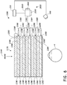
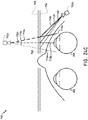
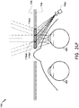
- FIG. 6 illustrates an example of a waveguide stack for outputting image information to a user.
- a display system 1000 includes a stack of waveguides, or stacked waveguide assembly, 1178 that may be utilized to provide three-dimensional perception to the eye/brain using a plurality of waveguides 1182, 1184, 1186, 1188, 1190.
- the display system 1000 is the system 80 of Figure 2 , with Figure 6 schematically showing some parts of that system 80 in greater detail.
- the waveguide assembly 1178 may be part of the display 62 of Figure 2 . It will be appreciated that the display system 1000 may be considered a light field display in some embodiments.
- the waveguide assembly 1178 may also include a plurality of features 1198, 1196, 1194, 1192 between the waveguides.
- the features 1198, 1196, 1194, 1192 may be one or more lenses.
- the waveguides 1182, 1184, 1186, 1188, 1190 and/or the plurality of lenses 1198, 1196, 1194, 1192 may be configured to send image information to the eye with various levels of wavefront curvature or light ray divergence. Each waveguide level may be associated with a particular depth plane and may be configured to output image information corresponding to that depth plane.
- Image injection devices 1200, 1202, 1204, 1206, 1208 may function as a source of light for the waveguides and may be utilized to inject image information into the waveguides 1182, 1184, 1186, 1188, 1190, each of which may be configured, as described herein, to distribute incoming light across each respective waveguide, for output toward the eye 4.
- the each of the input surfaces 1382, 1384, 1386, 1388, 1390 may be an edge of a corresponding waveguide, or may be part of a major surface of the corresponding waveguide (that is, one of the waveguide surfaces directly facing the world 1144 or the viewer's eye 4).
- a single beam of light e.g. a collimated beam
- a single one of the image injection devices 1200, 1202, 1204, 1206, 1208 may be associated with and inject light into a plurality (e.g., three) of the waveguides 1182, 1184, 1186, 1188, 1190.
- the image injection devices 1200, 1202, 1204, 1206, 1208 are discrete displays that each produce image information for injection into a corresponding waveguide 1182, 1184, 1186, 1188, 1190, respectively.
- the image injection devices 1200, 1202, 1204, 1206, 1208 are the output ends of a single multiplexed display which may, e.g., pipe image information via one or more optical conduits (such as fiber optic cables) to each of the image injection devices 1200, 1202, 1204, 1206, 1208.
- the image information provided by the image injection devices 1200, 1202, 1204, 1206, 1208 may include light of different wavelengths, or colors (e.g., different component colors, as discussed herein).
- the light injected into the waveguides 1182, 1184, 1186, 1188, 1190 is provided by a light projector system 2000, which comprises a light module 2040, which may include a light emitter, such as a light emitting diode (LED).
- the light from the light module 2040 may be directed to and modified by a light modulator 2030, e.g., a spatial light modulator, via a beam splitter 2050.
- the light modulator 2030 may be configured to change the perceived intensity of the light injected into the waveguides 1182, 1184, 1186, 1188, 1190.
- Examples of spatial light modulators include liquid crystal displays (LCD) including a liquid crystal on silicon (LCOS) displays.
- the display system 1000 may be a scanning fiber display comprising one or more scanning fibers configured to project light in various patterns (e.g., raster scan, spiral scan, Lissajous patterns, etc.) into one or more waveguides 1182, 1184, 1186, 1188, 1190 and ultimately to the eye 4 of the viewer.
- the illustrated image injection devices 1200, 1202, 1204, 1206, 1208 may schematically represent a single scanning fiber or a bundles of scanning fibers configured to inject light into one or a plurality of the waveguides 1182, 1184, 1186, 1188, 1190.
- the illustrated image injection devices 1200, 1202, 1204, 1206, 1208 may schematically represent a plurality of scanning fibers or a plurality of bundles of scanning, fibers each of which are configured to inject light into an associated one of the waveguides 1182, 1184, 1186, 1188, 1190.
- the one or more optical fibers may be configured to transmit light from the light module 2040 to the one or more waveguides 1182, 1184, 1186, 1188, 1190.
- one or more intervening optical structures may be provided between the scanning fiber, or fibers, and the one or more waveguides 1182, 1184, 1186, 1188, 1190 to, e.g., redirect light exiting the scanning fiber into the one or more waveguides 1182, 1184, 1186, 1188, 1190.
- a controller 1210 controls the operation of one or more of the stacked waveguide assembly 1178, including operation of the image injection devices 1200, 1202, 1204, 1206, 1208, the light source 2040, and the light modulator 2030.
- the controller 1210 is part of the local data processing module 70.
- the controller 1210 includes programming (e.g., instructions in a non-transitory medium) that regulates the timing and provision of image information to the waveguides 1182, 1184, 1186, 1188, 1190 according to, e.g., any of the various schemes disclosed herein.
- the controller may be a single integral device, or a distributed system connected by wired or wireless communication channels.
- the controller 1210 may be part of the processing modules 70 or 72 ( Figure 1 ) in some embodiments.
- the waveguides 1182, 1184, 1186, 1188, 1190 may be configured to propagate light within each respective waveguide by total internal reflection (TIR).
- the waveguides 1182, 1184, 1186, 1188, 1190 may each be planar or have another shape (e.g., curved), with major top and bottom surfaces and edges extending between those major top and bottom surfaces.
- the waveguides 1182, 1184, 1186, 1188, 1190 may each include outcoupling optical elements 1282, 1284, 1286, 1288, 1290 that are configured to extract light out of a waveguide by redirecting the light, propagating within each respective waveguide, out of the waveguide to output image information to the eye 4.
- Extracted light may also be referred to as outcoupled light and the outcoupling optical elements light may also be referred to light extracting optical elements.
- An extracted beam of light is outputted by the waveguide at locations at which the light propagating in the waveguide strikes a light extracting optical element.
- the outcoupling optical elements 1282, 1284, 1286, 1288, 1290 may, for example, be gratings, including diffractive optical features, as discussed further herein.
- the outcoupling optical elements 1282, 1284, 1286, 1288, 1290 may be disposed at the top and/or bottom major surfaces, and/or may be disposed directly in the volume of the waveguides 1182, 1184, 1186, 1188, 1190, as discussed further herein.
- the outcoupling optical elements 1282, 1284, 1286, 1288, 1290 may be formed in a layer of material that is attached to a transparent substrate to form the waveguides 1182, 1184, 1186, 1188, 1190.
- the waveguides 1182, 1184, 1186, 1188, 1190 may be a monolithic piece of material and the outcoupling optical elements 1282, 1284, 1286, 1288, 1290 may be formed on a surface and/or in the interior of that piece of material.
- each waveguide 1182, 1184, 1186, 1188, 1190 is configured to output light to form an image corresponding to a particular depth plane.
- the waveguide 1182 nearest the eye may be configured to deliver collimated light, as injected into such waveguide 1182, to the eye 4.
- the collimated light may be representative of the optical infinity focal plane.
- the next waveguide up 1184 may be configured to send out collimated light which passes through the first lens 1192 (e.g., a negative lens) before it can reach the eye 4; such first lens 1192 may be configured to create a slight convex wavefront curvature so that the eye/brain interprets light coming from that next waveguide up 1184 as coming from a first focal plane closer inward toward the eye 4 from optical infinity.
- first lens 1192 e.g., a negative lens
- the third up waveguide 1186 passes its output light through both the first 1192 and second 1194 lenses before reaching the eye 4; the combined optical power of the first 1192 and second 1194 lenses may be configured to create another incremental amount of wavefront curvature so that the eye/brain interprets light coming from the third waveguide 1186 as coming from a second focal plane that is even closer inward toward the person from optical infinity than was light from the next waveguide up 1184.
- the other waveguide layers 1188, 1190 and lenses 1196, 1198 are similarly configured, with the highest waveguide 1190 in the stack sending its output through all of the lenses between it and the eye for an aggregate focal power representative of the closest focal plane to the person.
- a compensating lens layer 1180 may be disposed at the top of the stack to compensate for the aggregate power of the lens stack 1198, 1196, 1194, 1192 below.
- Such a configuration provides as many perceived focal planes as there are available waveguide/lens pairings.
- Both the outcoupling optical elements of the waveguides and the focusing aspects of the lenses may be static (i.e., not dynamic or electro-active). In some alternative embodiments, either or both may be dynamic using electro-active features.
- two or more of the waveguides 1182, 1184, 1186, 1188, 1190 may have the same associated depth plane.
- multiple waveguides 1182, 1184, 1186, 1188, 1190 may be configured to output images set to the same depth plane, or multiple subsets of the waveguides 1182, 1184, 1186, 1188, 1190 may be configured to output images set to the same plurality of depth planes, with one set for each depth plane. This can provide advantages for forming a tiled image to provide an expanded field of view at those depth planes.
- the outcoupling optical elements 1282, 1284, 1286, 1288, 1290 may be configured to both redirect light out of their respective waveguides and to output this light with the appropriate amount of divergence or collimation for a particular depth plane associated with the waveguide.
- waveguides having different associated depth planes may have different configurations of outcoupling optical elements 1282, 1284, 1286, 1288, 1290, which output light with a different amount of divergence depending on the associated depth plane.
- the light extracting optical elements 1282, 1284, 1286, 1288, 1290 may be volumetric or surface features, which may be configured to output light at specific angles.
- the light extracting optical elements 1282, 1284, 1286, 1288, 1290 may be volume holograms, surface holograms, and/or diffraction gratings.
- the features 1198, 1196, 1194, 1192 may not be lenses; rather, they may simply be spacers (e.g., cladding layers and/or structures for forming air gaps).
- the outcoupling optical elements 1282, 1284, 1286, 1288, 1290 are diffractive features that form a diffraction pattern, or "diffractive optical element" (also referred to herein as a "DOE").
- the DOE's have a sufficiently low diffraction efficiency (a ratio of diffracted beam intensity to the incident beam intensity) so that only a portion of the light of the beam is deflected away toward the eye 4 with each intersection of the DOE, while the rest continues to move through a waveguide via total internal reflection.
- the light carrying the image information is thus divided into a number of related exit beams that exit the waveguide at a multiplicity of locations and the result is a fairly uniform pattern of exit emission toward the eye 4 for this particular collimated beam bouncing around within a waveguide.
- one or more DOEs may be switchable between "on” states in which they actively diffract, and "off” states in which they do not significantly diffract.
- a switchable DOE may comprise a layer of polymer dispersed liquid crystal, in which microdroplets comprise a diffraction pattern in a host medium, and the refractive index of the microdroplets may be switched to substantially match the refractive index of the host material (in which case the pattern does not appreciably diffract incident light) or the microdroplet may be switched to an index that does not match that of the host medium (in which case the pattern actively diffracts incident light).
- a camera assembly 500 may be provided to capture images of the eye 4 and/or tissue around the eye 4 to, e.g., detect user inputs and/or to monitor the physiological state of the user.
- a camera may be any image capture device.
- the camera assembly 500 may include an image capture device and a light source to project light (e.g., infrared light) to the eye, which may then be reflected by the eye and detected by the image capture device.
- the camera assembly 500 may be attached to the frame 64 ( Figure 2 ) and may be in electrical communication with the processing modules 70 and/or 72, which may process image information from the camera assembly 500 to make various determinations regarding, e.g., the physiological state of the user, as discussed herein. It will be appreciated that information regarding the physiological state of user may be used to determine the behavioral or emotional state of the user. Examples of such information include movements of the user and/or facial expressions of the user. The behavioral or emotional state of the user may then be triangulated with collected environmental and/or virtual content data so as to determine relationships between the behavioral or emotional state, physiological state, and environmental or virtual content data. In some embodiments, one camera assembly 500 may be utilized for each eye, to separately monitor each eye.
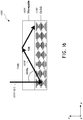
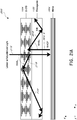
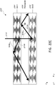
- FIG. 7 an example of exit beams outputted by a waveguide is shown.
- One waveguide is illustrated, but it will be appreciated that other waveguides in the waveguide assembly 1178 ( Figure 6 ) may function similarly, where the waveguide assembly 1178 includes multiple waveguides.
- Light 400 is injected into the waveguide 1182 at the input surface 1382 of the waveguide 1182 and propagates within the waveguide 1182 by TIR. At points where the light 400 impinges on the DOE 1282, a portion of the light exits the waveguide as exit beams 402.
- the exit beams 402 are illustrated as substantially parallel but, as discussed herein, they may also be redirected to propagate to the eye 4 at an angle (e.g., forming divergent exit beams), depending on the depth plane associated with the waveguide 1182. It will be appreciated that substantially parallel exit beams may be indicative of a waveguide with outcoupling optical elements that outcouple light to form images that appear to be set on a depth plane at a large distance (e.g., optical infinity) from the eye 4.
- waveguides or other sets of outcoupling optical elements may output an exit beam pattern that is more divergent, which would require the eye 4 to accommodate to a closer distance to bring it into focus on the retina and would be interpreted by the brain as light from a distance closer to the eye 4 than optical infinity.
- a full color image may be formed at each depth plane by overlaying images in each of the component colors, e.g., three or more component colors.
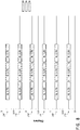
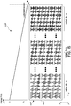
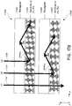
- Figure 8 illustrates an example of a stacked waveguide assembly in which each depth plane includes images formed using multiple different component colors.
- the illustrated embodiment shows depth planes 14a - 14f, although more or fewer depths are also contemplated.
- Each depth plane may have three component color images associated with it: a first image of a first color, G; a second image of a second color, R; and a third image of a third color, B.
- Different depth planes are indicated in the figure by different numbers for diopters (dpt) following the letters G, R, and B.
- the numbers following each of these letters indicate diopters (1/m), or inverse distance of the depth plane from a viewer, and each box in the figures represents an individual component color image.
- the exact placement of the depth planes for different component colors may vary. For example, different component color images for a given depth plane may be placed on depth planes corresponding to different distances from the user Such an arrangement may increase visual acuity and user comfort and/or may decrease chromatic aberrations.
- each depth plane may have multiple waveguides associated with it.
- each box in the figures including the letters G, R, or B may be understood to represent an individual waveguide, and three waveguides may be provided per depth plane where three component color images are provided per depth plane. While the waveguides associated with each depth plane are shown adjacent to one another in this drawing for ease of description, it will be appreciated that, in a physical device, the waveguides may all be arranged in a stack with one waveguide per level. In some other embodiments, multiple component colors may be outputted by the same waveguide, such that, e.g., only a single waveguide may be provided per depth plane.
- G is the color green
- R is the color red
- B is the color blue.
- other colors associated with other wavelengths of light including magenta and cyan, may be used in addition to or may replace one or more of red, green, or blue.
- features 198, 196, 194, and 192 may be active or passive optical filters configured to block or selectively light from the ambient environment to the viewer's eyes.
- references to a given color of light throughout this disclosure will be understood to encompass light of one or more wavelengths within a range of wavelengths of light that are perceived by a viewer as being of that given color.
- red light may include light of one or more wavelengths in the range of about 620-780 nm
- green light may include light of one or more wavelengths in the range of about 492-577 nm
- blue light may include light of one or more wavelengths in the range of about 435-493 nm.
- the light source 2040 ( Figure 6 ) may be configured to emit light of one or more wavelengths outside the visual perception range of the viewer, for example, infrared and/or ultraviolet wavelengths.
- the incoupling, outcoupling, and other light redirecting structures of the waveguides of the display 1000 may be configured to direct and emit this light out of the display towards the user's eye 4, e.g., for imaging and/or user stimulation applications.
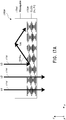
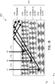
- FIG. 9A illustrates a cross-sectional side view of an example of a plurality or set 1200 of stacked waveguides that each includes an incoupling optical element.
- the waveguides may each be configured to output light of one or more different wavelengths, or one or more different ranges of wavelengths.
- the stack 1200 may correspond to the stack 1178 ( Figure 6 ) and the illustrated waveguides of the stack 1200 may correspond to part of the plurality of waveguides 1182, 1184, 1186, 1188, 1190, except that light from one or more of the image injection devices 1200, 1202, 1204, 1206, 1208 is injected into the waveguides from a position that requires light to be redirected for incoupling.
- the illustrated set 1200 of stacked waveguides includes waveguides 1210, 1220, and 1230.
- Each waveguide includes an associated incoupling optical element (which may also be referred to as a light input area on the waveguide), with, e.g., incoupling optical element 1212 disposed on a major surface (e.g., an upper major surface) of waveguide 1210, incoupling optical element 1224 disposed on a major surface (e.g., an upper major surface) of waveguide 1220, and incoupling optical element 1232 disposed on a major surface (e.g., an upper major surface) of waveguide 1230.
- incoupling optical element 1212 disposed on a major surface (e.g., an upper major surface) of waveguide 1210
- incoupling optical element 1224 disposed on a major surface (e.g., an upper major surface) of waveguide 1220
- incoupling optical element 1232 disposed on a major surface (e.g., an upper major surface) of waveguide 12
- one or more of the incoupling optical elements 1212, 1222, 1232 may be disposed on the bottom major surface of the respective waveguide 1210, 1220, 1230 (particularly where the one or more incoupling optical elements are reflective, deflecting optical elements). As illustrated, the incoupling optical elements 1212, 1222, 1232 may be disposed on the upper major surface of their respective waveguide 1210, 1220, 1230 (or the top of the next lower waveguide), particularly where those incoupling optical elements are transmissive, deflecting optical elements. In some embodiments, the incoupling optical elements 1212, 1222, 1232 may be disposed in the body of the respective waveguide 1210, 1220, 1230.
- the incoupling optical elements 1212, 1222, 1232 are wavelength selective, such that they selectively redirect one or more wavelengths of light, while transmitting other wavelengths of light. While illustrated on one side or corner of their respective waveguide 1210, 1220, 1230, it will be appreciated that the incoupling optical elements 1212, 1222, 1232 may be disposed in other areas of their respective waveguide 1210, 1220, 1230 in some embodiments.
- each incoupling optical element 1212, 1222, 1232 may be laterally offset from one another.
- each incoupling optical element may be offset such that it receives light without that light passing through another incoupling optical element.
- each incoupling optical element 1212, 1222, 1232 may be configured to receive light from a different image injection device 1200, 1202, 1204, 1206, and 1208 as shown in Figure 6 , and may be separated (e.g., laterally spaced apart) from other incoupling optical elements 1212, 1222, 1232 such that it substantially does not receive light from the other ones of the incoupling optical elements 1212, 1222, 1232.
- Each waveguide also includes associated light distributing elements, with, e.g., light distributing elements 1214 disposed on a major surface (e.g., a top major surface) of waveguide 1210, light distributing elements 1224 disposed on a major surface (e.g., a top major surface) of waveguide 1220, and light distributing elements 1234 disposed on a major surface (e.g., a top major surface) of waveguide 1230.
- the light distributing elements 1214, 1224, 1234 may be disposed on a bottom major surface of associated waveguides 1210, 1220, 1230, respectively.
- the light distributing elements 1214, 1224, 1234 may be disposed on both top and bottom major surface of associated waveguides 1210, 1220, 1230, respectively; or the light distributing elements 1214, 1224, 1234, may be disposed on different ones of the top and bottom major surfaces in different associated waveguides 1210, 1220, 1230, respectively.
- the waveguides 1210, 1220, 1230 may be spaced apart and separated by, e.g., gas, liquid, and/or solid layers of material.
- layer 1218a may separate waveguides 1210 and 1220; and layer 1218b may separate waveguides 1220 and 1230.
- the layers 1218a and 1218b are formed of low refractive index materials (that is, materials having a lower refractive index than the material forming the immediately adjacent one of waveguides 1210, 1220, 1230).
- the refractive index of the material forming the layers 1218a, 1218b is 0.05 or more, or 0.10 or more less than the refractive index of the material forming the waveguides 1210, 1220, 1230.
- the lower refractive index layers 1218a, 1218b may function as cladding layers that facilitate total internal reflection (TIR) of light through the waveguides 1210, 1220, 1230 (e.g., TIR between the top and bottom major surfaces of each waveguide).
- the layers 1218a, 1218b are formed of air. While not illustrated, it will be appreciated that the top and bottom of the illustrated set 1200 of waveguides may include immediately neighboring cladding layers.
- the material forming the waveguides 1210, 1220, 1230 are similar or the same, and the material forming the layers 1218a, 1218b are similar or the same.
- the material forming the waveguides 1210, 1220, 1230 may be different between one or more waveguides, and/or the material forming the layers 1218a, 1218b may be different, while still holding to the various refractive index relationships noted above.
- light rays 1240, 1242, 1244 are incident on the set 1200 of waveguides. It will be appreciated that the light rays 1240, 1242, 1244 may be injected into the waveguides 1210, 1220, 1230 by one or more image injection devices 1200, 1202, 1204, 1206, 1208 ( Figure 6 ).
- the light rays 1240, 1242, 1244 have different properties, e.g., different wavelengths or different ranges of wavelengths, which may correspond to different colors.
- the incoupling optical elements 1212, 122, 1232 each deflect the incident light such that the light propagates through a respective one of the waveguides 1210, 1220, 1230 by TIR.
- incoupling optical element 1212 may be configured to deflect ray 1240, which has a first wavelength or range of wavelengths.
- the transmitted ray 1242 impinges on and is deflected by the incoupling optical element 1222, which is configured to deflect light of a second wavelength or range of wavelengths.
- the ray 1244 is deflected by the incoupling optical element 1232, which is configured to selectively deflect light of third wavelength or range of wavelengths.
- the deflected light rays 1240, 1242, 1244 are deflected so that they propagate through a corresponding waveguide 1210, 1220, 1230; that is, the incoupling optical elements 1212, 1222, 1232 of each waveguide deflects light into that corresponding waveguide 1210, 1220, 1230 to incouple light into that corresponding waveguide.
- the light rays 1240, 1242, 1244 are deflected at angles that cause the light to propagate through the respective waveguide 1210, 1220, 1230 by TIR.
- the light rays 1240, 1242, 1244 propagate through the respective waveguide 1210, 1220, 1230 by TIR until impinging on the waveguide's corresponding light distributing elements 1214, 1224, 1234.
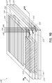
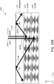
- FIG. 9B a perspective view of an example of the plurality of stacked waveguides of Figure 9A is illustrated.
- the incoupled light rays 1240, 1242, 1244 are deflected by the incoupling optical elements 1212, 1222, 1232, respectively, and then propagate by TIR within the waveguides 1210, 1220, 1230, respectively.
- the light rays 1240, 1242, 1244 then impinge on the light distributing elements 1214, 1224, 1234, respectively.
- the light distributing elements 1214, 1224, 1234 deflect the light rays 1240, 1242, 1244 so that they propagate towards the outcoupling optical elements 1250, 1252, 1254, respectively.
- the light distributing elements 1214, 1224, 1234 are orthogonal pupil expanders (OPE's).
- OPE's both deflect or distribute light to the outcoupling optical elements 1250, 1252, 1254 and also increase the beam or spot size of this light as it propagates to the outcoupling optical elements.
- the light distributing elements 1214, 1224, 1234 may be omitted and the incoupling optical elements 1212, 1222, 1232 may be configured to deflect light directly to the outcoupling optical elements 1250, 1252, 1254.
- the light distributing elements 1214, 1224, 1234 may be replaced with outcoupling optical elements 1250, 1252, 1254, respectively.
- the outcoupling optical elements 1250, 1252, 1254 are exit pupils (EP's) or exit pupil expanders (EPE's) that direct light in a viewer's eye 4 ( Figure 7 ).
- the set 1200 of waveguides includes waveguides 1210, 1220, 1230; incoupling optical elements 1212, 1222, 1232; light distributing elements (e.g., OPE's) 1214, 1224, 1234; and outcoupling optical elements (e.g., EP's) 1250, 1252, 1254 for each component color.
- the waveguides 1210, 1220, 1230 may be stacked with an air gap/cladding layer between each one.
- the incoupling optical elements 1212, 1222, 1232 redirect or deflect incident light (with different incoupling optical elements receiving light of different wavelengths) into its waveguide.
- light ray 1240 (e.g., blue light) is deflected by the first incoupling optical element 1212, and then continues to bounce down the waveguide, interacting with the light distributing element (e.g., OPE's) 1214 and then the outcoupling optical element (e.g., EPs) 1250, in a manner described earlier.
- the light rays 1242 and 1244 (e.g., green and red light, respectively) will pass through the waveguide 1210, with light ray 1242 impinging on and being deflected by incoupling optical element 1222.
- the light ray 1242 then bounces down the waveguide 1220 via TIR, proceeding on to its light distributing element (e.g., OPEs) 1224 and then the outcoupling optical element (e.g., EP's) 1252.
- light ray 1244 (e.g., red light) passes through the waveguide 1220 to impinge on the light incoupling optical elements 1232 of the waveguide 1230.
- the light incoupling optical elements 1232 deflect the light ray 1244 such that the light ray propagates to light distributing element (e.g., OPEs) 1234 by TIR, and then to the outcoupling optical element (e.g., EPs) 1254 by TIR.
- the outcoupling optical element 1254 then finally outcouples the light ray 1244 to the viewer, who also receives the outcoupled light from the other waveguides 1210, 1220.
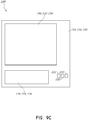
- Figure 9C illustrates a top-down plan view of an example of the plurality of stacked waveguides of Figures 9A and 9B .
- the waveguides 1210, 1220, 1230, along with each waveguide's associated light distributing element 1214, 1224, 1234 and associated outcoupling optical element 1250, 1252, 1254 may be vertically aligned.
- the incoupling optical elements 1212, 1222, 1232 are not vertically aligned; rather, the incoupling optical elements are preferably non-overlapping (e.g., laterally spaced apart as seen in the top-down view).
- this nonoverlapping spatial arrangement facilitates the injection of light from different resources into different waveguides on a one-to-one basis, thereby allowing a specific light source to be uniquely coupled to a specific waveguide.
- arrangements including nonoverlapping spatially-separated incoupling optical elements may be referred to as a shifted pupil system, and the in coupling optical elements within these arrangements may correspond to sub pupils.
- liquid crystals possess physical properties that may be intermediate between conventional fluids and solids. While liquid crystals are fluid-like in some aspects, unlike most fluids, the arrangement of molecules within liquid crystals exhibits some structural order. Different types of liquid crystals include thermotropic, lyotropic, and polymeric liquid crystals. Thermotropic liquid crystals disclosed herein can be implemented in various physical states, e.g., phases, including a nematic state/phase, a smectic state/phase, a chiral nematic state/phase or a chiral smectic state/phase.
- liquid crystals in a nematic state or phase can have calamitic (rod-shaped) or discotic (disc-shaped) organic molecules that have relatively little positional order, while having a long-range directional order with their long axes being roughly parallel.
- the organic molecules may be free to flow with their center of mass positions being randomly distributed as in a liquid, while still maintaining their long-range directional order.
- liquid crystals in a nematic phase can be uniaxial; i.e., the liquid crystals have one axis that is longer and preferred, with the other two being roughly equivalent.
- liquid crystals can be biaxial; i.e., in addition to orienting their long axis, the liquid crystals may also orient along a secondary axis.
- liquid crystals in a smectic state or phase can have the organic molecules that form relatively well-defined layers that can slide over one another.
- liquid crystals in a smectic phase can be positionally ordered along one direction.
- the long axes of the molecules can be oriented along a direction substantially normal to the plane of the liquid crystal layer, while in other implementations, the long axes of the molecules may be tilted with respect to the direction normal to the plane of the layer.
- nematic liquid crystals are composed of rod-like molecules with the long axes of neighboring molecules approximately aligned to one another.
- a dimensionless unit vector n called the director, may be used to describe the direction of preferred orientation of the liquid crystal molecules.
- a tilt angle or a pre-tilt angle ⁇ can refer to an angle measured in a plane perpendicular to a major surface (in an x-y plane) of the liquid crystal layers or of the substrate, e.g., the x-z plane, and measured between an alignment direction and the major surface or a direction parallel to the major surface, e.g., the x-direction.
- an azimuthal angle or a rotation angle ⁇ is used to describe an angle of rotation about a layer normal direction, or an axis normal to a major surface of a liquid crystal layer, which is measured in a plane parallel to a major surface of the liquid crystal layers or of the substrate, e.g., the x-y plane, and measured between an alignment direction, e.g., an elongation direction or the direction of the director, and a direction parallel to the major surface, e.g., the y-direction.
- an angle such as the rotation angle ⁇ or a pre-tilt angle ⁇ are referred to as being substantially the same between different regions, it will be understood that an average alignment angles can, for example, be within about 1%, about 5% or about 10% of each other although the average alignment can be larger in some cases.
- a duty cycle can, for example, refers to a ratio between a first lateral dimension of a first region having liquid crystal molecules aligned in a first alignment direction, and the grating period of the zone having the first region.
- the first region corresponds to the region in which the alignment of the liquid crystals does not vary between different zones.
- liquid crystals in a nematic state or a smectic state can also exhibit chirality. Such liquid crystals are referred to as being in a chiral phase or a cholesteric phase. In a chiral phase or a cholesteric phase, the liquid crystals can exhibit a twisting of the molecules perpendicular to the director, with the molecular axis parallel to the director. The finite twist angle between adjacent molecules is due to their asymmetric packing, which results in longer-range chiral order.
- liquid crystals in a chiral smectic state or phase can be configured such that the liquid crystal molecules have positional ordering in a layered structure, with the molecules tilted by a finite angle with respect to the layer normal.
- chirality can induce successive azimuthal twists of the liquid crystal molecules with respect to a direction perpendicular to the layer normal from one liquid crystal molecule to the next liquid crystal molecule in the layer normal direction, thereby producing a spiral twisting of the molecular axis along the layer normal.
- a chiral structure refers to a plurality of liquid crystal molecules in a cholesteric phase that extend in a direction, e.g., a direction perpendicular to the director such as a layer depth direction, and are successively rotated or twisted in a rotation direction, e.g., clockwise or counterclockwise.
- the directors of the liquid crystal molecules in a chiral structure can be characterized as a helix having a helical pitch.
- liquid crystals in a cholesteric phase displaying chirality can be described as having a chiral pitch, or a helical pitch (p), which corresponds to a length in the layer depth direction corresponding to a net rotation angle of the liquid crystal molecules of the chiral structures by one full rotation in the first rotation direction.
- p a helical pitch
- the helical pitch refers to the distance over which the liquid crystal molecules undergo a full 360° twist.
- the helical pitch (p) can change, e.g., when the temperature is altered or when other molecules are added to a liquid crystal host (an achiral liquid host material can form a chiral phase if doped with a chiral material), allowing the helical pitch (p) of a given material to be tuned accordingly.
- the helical pitch is of the same order as the wavelength of visible light.
- liquid crystals displaying chirality can also be described as having a twist angle, or a rotation angle ( ⁇ ), which can refer to, for example, the relative azimuthal angular rotation between successive liquid crystal molecules in the layer normal direction, and as having a net twist angle, or a net rotation angle, which can refer to, for example, the relative azimuthal angular rotation between an uppermost liquid crystal molecule and a lowermost liquid crystal molecule across a specified length, e.g., the length of a chiral structure or the thickness of the liquid crystal layer.
- ⁇ rotation angle
- liquid crystals having various states or phases as described above can be configured to offer various desirable material properties, including, e.g., birefringence, optical anisotropy, and manufacturability using thin-film processes.
- grating structures that exhibit spatially varying diffraction properties, e.g., gradient diffraction efficiencies, can be fabricated.
- polymerizable liquid crystals may refer to liquid crystal materials that can be polymerized, e.g., in-situ photopolymerized, and may also be described herein as reactive mesogens (RM).
- RM reactive mesogens
- liquid crystal molecules may be polymerizable in some embodiments and, once polymerized, may form a large network with other liquid crystal molecules.
- the liquid crystal molecules may be linked by chemical bonds or linking chemical species to other liquid crystal molecules. Once joined together, the liquid crystal molecules may form liquid crystal domains having substantially the same orientations and locations as before being linked together.
- the term "liquid crystal molecule" is used herein to refer to both the liquid crystal molecules before polymerization and to the liquid crystal domains formed by these molecules after polymerization.
- photopolymerizable liquid crystal materials can be configured to form Bragg-reflective or diffractive structures, e.g., a diffraction grating, whose material properties, including birefringence, chirality, and ease for multiple-coating, can be utilized to create diffraction gratings with different material properties, e.g., birefringence, chirality, and thickness, which can result in different optical properties, e.g., diffraction efficiency, wavelength selectivity and off-axis diffraction angle selectivity, to name a few.
- Bragg-reflective or diffractive structures e.g., a diffraction grating, whose material properties, including birefringence, chirality, and ease for multiple-coating, can be utilized to create diffraction gratings with different material properties, e.g., birefringence, chirality, and thickness, which can result in different optical properties, e.g., diffraction efficiency
- a "transmissive" or “transparent” structure e.g., a transparent substrate
- a transparent substrate may be a glass, sapphire or a polymeric substrate in some embodiments.
- a "reflective" structure e.g., a reflective substrate, may reflect at least some, e.g., at least 20, 30, 50, 70, 90% or more of the incident light, to reflect therefrom.
- Optical properties of a grating are determined by the physical structures of the grating (e.g., the periodicity, the depth, and the duty cycle), as well as material properties of the grating (e.g., refractive index, absorption, and birefringence).
- material properties of the grating e.g., refractive index, absorption, and birefringence.
- optical properties of the grating can be controlled by controlling, e.g., molecular orientation or distribution of the liquid crystal materials. For example, by varying molecular orientation or distribution of the liquid crystal material across the grating area, the grating may exhibit graded diffraction efficiencies. Such approaches are described in the following, in reference to the figures.
- display systems may include optical elements, e.g., incoupling optical elements, outcoupling optical elements, and light distributing elements, which may include diffraction gratings.
- optical elements e.g., incoupling optical elements, outcoupling optical elements, and light distributing elements, which may include diffraction gratings.
- light 400 that is injected into the waveguide 1182 at the input surface 1382 of the waveguide 1182 propagates within the waveguide 1182 by total internal reflection (TIR).
- TIR total internal reflection
- any of the optical elements 1182, 1282, or 1382 can be configured as a diffraction grating.
- Efficient light in-coupling into (or out-coupling from) the waveguide 1182 can be a challenge in designing a waveguide-based see-through displays, e.g., for virtual/augmented/mixed display applications.
- the desirable diffraction properties include, among other properties, polarization selectivity, spectral selectivity, angular selectivity, high spectral bandwidth and high diffraction efficiencies, among other properties.
- the optical element 1282 is configured as a cholesteric liquid crystal diffraction grating (CLCG).
- CLCGs can be configured to optimize, among other things, polarization selectivity, bandwidth, phase profile, spatial variation of diffraction properties, spectral selectivity and high diffraction efficiencies.
- CLCGs configured as a reflective liquid crystal diffraction grating comprising cholesteric liquid crystals (CLC) optimized for various optical properties
- CLC cholesteric liquid crystals
- diffraction gratings have a periodic structure, which splits and diffracts light into several beams travelling in different directions. The directions of these beams depend, among other things, on the period of the periodic structure and the wavelength of the light.
- various material properties of the CLC can be optimized as described infra.
- liquid crystal molecules of a cholesteric liquid crystal (CLC) layer in a chiral (nematic) phase or a cholesteric phase is characterized by a plurality of liquid crystal molecules that are arranged to have successive azimuthal twists of the director as a function of position in the film in a normal direction, or a depth direction, of the liquid crystal layer.
- the liquid crystal molecules that arranged to have the successive azimuthal twists are collectively referred to herein as a chiral structure.
- an angle ( ⁇ ) of azimuthal twist or rotation is described as the angle between the directors the liquid crystal molecules, as described supra , relative to a direction parallel to the layer normal.
- the spatially varying director of the liquid crystal molecules of a chiral structure can be described as forming a helical pattern in which the helical pitch (p) is defined as the distance (e.g., in the layer normal direction of the liquid crystal layer) over which the director has rotated by 360°, as described above.
- a CLC layer configured as a diffraction grating has a lateral dimension by which the molecular structures of the liquid crystals periodically repeat in a lateral direction normal to the depth direction. This periodicity in the lateral direction is referred to as a grating period ( ⁇ ).
- a diffraction grating comprises a cholesteric liquid crystal (CLC) layer comprising a plurality of chiral structures, wherein each chiral structure comprises a plurality of liquid crystal molecules that extend in a layer depth direction by at least a helical pitch and are successively rotated in a first rotation direction.
- the helical pitch is a length in the layer depth direction corresponding to a net rotation angle of the liquid crystal molecules of the chiral structures by one full rotation in the first rotation direction.
- the arrangements of the liquid crystal molecules of the chiral structures vary periodically in a lateral direction perpendicular to the layer depth direction
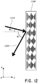
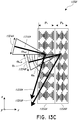
- FIG 10 illustrates a cross-sectional side view of a cholesteric liquid crystal (CLC) layer 1004 comprising a plurality of uniform chiral structures, according to embodiments.
- the CLC 1004 comprises a CLC layer 1008 comprising liquid crystal molecules arranged as a plurality of chiral structures 1012-1, 1012-2,... 1012-i, wherein each chiral structure comprises a plurality of liquid crystal molecules, where is any suitable integer greater than 2.
- the chiral structure 1012-1 comprises a plurality of liquid crystal molecules 1012-1-1, 1012-1-2,...1012-1-j that are arranged to extend in a layer normal direction, e.g., the z-direction in the illustrated embodiment, where j is any suitable integer greater than 2.
- the liquid crystal molecules of each chiral structure are successively rotated in a first rotation direction.
- the liquid crystal molecules are successively rotated in a clockwise direction when viewing in a positive direction of the z-axis (i.e., the direction of the axis arrow), or the direction of propagation of the incident light beams 1016-L, 1016-R.
- the liquid crystal molecules 1012-1-1, 1012-1-2,...1012-1-j of the chiral structure 1012-1 are successively rotated by rotation angles ⁇ 1 , ⁇ 2 ,... ⁇ j , relative to, e.g., the positive x-direction.
- the plurality of liquid crystal molecules of each of the chiral structures 1012-1, 1012-2,... 1012-i between opposing ends in the z-direction are rotated by one full rotation or turn, such that the net rotation angle of the liquid crystal molecules is about 360°.
- the chiral structures 1012-1, 1012-2,... 1012-i have a length L in the z-direction that is the same as the helical pitch p.
- embodiments are not so limited, and the chiral structures 1012-1, 1012-2,...
- the 1012-i can have any number of full rotations greater than or less than 1, any suitable net rotation angle that is lower or higher than 360°, and/or any suitable length L in the z-direction that is shorter or longer than the helical pitch p.
- the number of full turns of the chiral structures can be between 1 and 3, between 2 and 4, between 3 and 5, between 4 and 6, between 5 and 7, between 6 and 8, between 7 and 9, or between 8 and 10, among other numbers.
- the successive rotation angles between adjacent liquid crystal molecules in the z-direction, ⁇ 1 , ⁇ 2 ,... ⁇ j can be the same according to some embodiments, or be different according to some other embodiments.
- the length of the chiral structures 1012-1, 1012-2,...1012-i is about p and the net rotation angle is 360°, such that adjacent liquid crystal molecules in the z-direction are rotated by about 360°/(m-1), where m is the number of liquid crystal molecules in a chiral structure.
- each of the chiral structure 1012-1, 1012-2,... 1012-i has 13 liquid crystal molecules, such that adjacent liquid crystal molecules in the z-direction are rotated with respect to each other by about 30°.
- chiral structures in various embodiments can have any suitable number of liquid crystal molecules.
- the chiral structures that are adjacent in a lateral direction have similarly arranged liquid crystal molecules.
- the chiral structures 1012-1, 1012-2,... 1012-i are similarly configured such that liquid crystal molecules of the different chiral structures that are at about the same depth, e.g., the liquid crystal molecules closest to the light-incident surface 1004S, have the same rotation angle, as well as successive rotation angles of successive liquid crystal molecules at about the same depth, as well as the net rotation angle of the liquid crystal molecules of each chiral structure.
- the CLC layer 1004 illustrated in Figure 10 is further described in operation, according to embodiments.
- the CLC layer 1004 comprises the chiral structures 1012-1, 1012-2,... 1012-i having a uniform arrangement in a lateral direction, e.g., x-direction.
- incident light having a combination of light beams having left-handed circular polarization and light beams having right-handed circular polarization are incident on the surface 1004S of the CLC layer 1008, by Bragg-reflection or diffraction, light with one of the circular polarization handedness is reflected by the CLC layer 1004, while light with the opposite polarization handedness is transmitted through the CLC layer 1008 without substantial interference.
- the handedness is defined as viewed in the direction of propagation.
- the direction of polarization, or handedness of the polarization, of the light beams 1016-L, 1016-R is matched such that it and has the same direction of rotation as the liquid crystal molecules of the chiral structures 1012-1, 1012-2,... 1012-i
- the incident light is reflected.
- incident on the surface 1004S are light beams 1016-L having left-handed circular polarization and light beams 1016-R having a right-handed circular polarization.
- the wavelength of the incident light may be proportional to the mean or average refractive index (n) of a CLC layer and to the helical pitch (p), and can be expressed as satisfying the following condition under some circumstances: ⁇ ⁇ np
- the bandwidth ⁇ is about 60 nm, about 80 nm or about 100 nm.
- a peak reflected intensity within a visible wavelength range between, e.g., about 390 nm and about 700 nm, or within a near infrared wavelength range between, e.g., about 700 nm and about 2500 nm can exceed about 60%, about 70%, about 80% or about 90%.
- the full width at half maximum (FWHM) can be less than about 100 nm, less than about 70 nm, less than about 50 nm or less than about 20 nm.
- Figure 11 illustrates a cross-sectional side view of a CLC grating (CLCG) 1150 having differently arranged chiral structures in a lateral direction, e.g., varying twist angles in a lateral direction, according to embodiments.
- the diffraction grating 1150 comprises a cholesteric liquid crystal (CLC) layer 1158 comprising liquid crystal molecules arranged as a plurality of chiral structures 1162-1, 1162-2,... 1162-i, wherein each chiral structure comprises a plurality of liquid crystal molecules.
- the chiral structure 1162-1 comprises a plurality of liquid crystal molecules 1162-1-1, 1162-1-2,...
- each chiral structure is successively rotated in a first rotation direction in a similar manner as described with respect to Figure 10 .
- various other parameters of the chiral structures including the length L, the number of full rotations made by the liquid crystal molecules and the number of liquid crystal molecules per chiral structure are similar to the chiral structures described above with respect to Figure 10 .
- the chiral structures that are adjacent in a lateral direction have differently arranged liquid crystal molecules.
- the chiral structures 1162-1, 1162-2,... 1162-i are differently configured in the x-direction such that the liquid crystal molecules of the different chiral structures at about the same depth have different rotation angles.
- the net rotation angle of the liquid crystal molecules 1162-1-1, 1162-2-1,... 1162-i-1, that are closest to the incident surface 1158S across a lateral length A, which corresponds to a period of the diffraction grating 1150, is a rotation angle of about 180°.
- liquid crystal molecules of different chiral structures that are disposed at about the same depth level are rotated by about the same rotation angle relative to respective surface-most liquid crystal molecules..
- the successive rotation angles ⁇ 1 , ⁇ 2 ,... ⁇ i of liquid crystal molecules that are at the same depth level across the period A in the x-direction can be the same according to some embodiments, or be different according to some other embodiments.
- adjacent liquid crystal molecules in the x-direction are rotated by about 360°/(m-1), where m is the number of liquid crystal molecules spanned by a period ⁇ in the x-direction.
- liquid crystal molecules that span across the period ⁇ , such that adjacent liquid crystal molecules at the same vertical level in the x-direction are rotated with respect to each other by about 30°.
- chiral structures in various embodiments can have any suitable number of liquid crystal molecules.
- the CLC layer 1158 is illustrated to have only one period A.
- embodiments are not so limited, and the CLC layer 1158 can have any suitable number of periods that is determined by the lateral dimension of the CLCG in the x-direction.
- the successively rotated chiral structures induce shifts in the relative phases of the reflected light along the x-direction.
- graph 1170 plots the phase change ⁇ resulting from the chiral structures that are successively rotated by rotation angles ⁇ 1 , ⁇ 2 ,... ⁇ i in the x-axis direction in one period A.
- the bandwidth can be expressed as ⁇ ⁇ ⁇ n ⁇ p.
- the Bragg-reflected wavelength can be varied by varying the helical pitch p of the chiral structures.
- the helical pitch p can be varied by increasing or decreasing helical twisting power (HTP), which refers to the ability of a chiral compound to induce the rotation or twist angles as described above.
- HTP helical twisting power
- the HTP can in turn be varied by changing the amount of chiral compound relative to the amount of non-chiral compound.
- the Bragg-reflection wavelength and thus the color can be varied based on an inverse relationship between the relative fraction of the chiral compound and the helical pitch.
- the ratio of the amount of chiral compound to the amount of nonchiral compound can be about 20:1, 10:1, 5:1, 4:1, 3:1, 2:1, 1:1, 1:2, 1:3, 1:4, 1:5, 1:10 or about 1:20 by weight.
- the incident light beams 1016-L, 1016-R are illustrated as being propagating in a direction parallel to the layer normal, e.g., in the z-direction.
- light propagating within the waveguide 1182 e.g., propagating by total internal reflection (TIR)
- TIR total internal reflection
- the outcoupling optical elements 1282, 1284, 1286, 1288, 1290 e.g., diffraction gratings, at an off-axis angle.
- the diffraction gratings described herein can be configured to maximize bandwidth and diffraction efficiency for such configurations, as described below.
- the liquid crystal molecules are illustrated to not be pre-tilted. Embodiment are not so limited, however, and the liquid crystal molecules can have a pre-tilt angle ⁇ , relative to a direction parallel to a major surface of the CLCG, e.g., relative to the x-y plane that is between about +/-60 degrees and about +/-90 degrees or between about +/-65 degrees and about +/-85 degrees, for instance about +/-75 degree; between about +/-35 degrees and about +/-65 degrees or between about +/-40 degrees and about +/-60 degrees, for instance about +/-50 degrees; between about +/-10 degrees and about +/-40 degrees or between about +/-15 degrees and about +/-35 degrees, for instance about +/-25 degrees, according to some embodiments. According to some other embodiments, the pre-tilt angle ⁇ can be between about ⁇ 15 degrees or between about ⁇ 10 degrees or between about ⁇ 5, e.g., 0 degrees.
- Figure 12 illustrates a cross-sectional side view of a CLC layer 1158 configured for high bandwidth of reflection at an off-axis incident angle, according to embodiments.
- an off-axis incident angle refers an angle of incidence ⁇ inc of an incident beam 1216 with respect to the direction of layer normal (e.g., z-direction in Figure 12 ) that has a non-zero value, resulting in a Bragg-reflected beam 1220 at a reflection angle ⁇ .
- the reflection angle can be varied to a limited extent by varying a ⁇ / ⁇ .
- ⁇ inc the incident angle relative to the direction of layer normal
- ⁇ the reflection angle relative to the direction of layer normal
- n is a reflective index of a medium in which the reflected beam propagates.
- the ratio ⁇ / ⁇ can have a value between 0.5 and 0.8, between 0.6 and 0.9, between 0.7 and 1.0, between 0.8 and 1.1, between 0.9 and 1.2, between 1.0 and 1.6, between 1.1 and 1.5, or between 1.2 and 1.4.
- the off-axis angle at which the CLC layer 1158 is configured to Bragg-reflect with high efficiency can also depend on the helical pitch p of the chiral structures.
- FIGS 13A and 13B illustrate cross-sectional side views of CLC layers configured for reflection at off-axis incident angles, according to embodiments.
- a first cholesteric liquid crystal (CLC) layer 1358A comprises a first plurality of chiral structures having a first helical pitch (p 1 ).
- the first CLC layer 1358A has a first helical pitch p1 such that Bragg-reflection is at a maximum when a first incident light beam 1316A is directed to an incident surface of the CLC layer 1358Aat a first off-axis angle ⁇ inc , 1 , which results in a first reflected light beam 1320A at a first reflection angle ⁇ 1 .
- the CLC layer 1358A is further configured to have a first range 1324A of off-axis incident angles in which relatively high diffraction efficiency can be obtained.
- the first range 1324A can correspond to a range of off-axis incident angles outside of which the intensity of the first reflected light beam 1320A falls off by more than, e.g., 1/e.
- the first range 1324A can have values of, ⁇ inc , 1 ⁇ 3°, ⁇ inc , 1 ⁇ 5°, ⁇ inc , 1 ⁇ 7°, ⁇ inc , 1 ⁇ 10° or ⁇ inc , 1 ⁇ 20°.
- a second cholesteric liquid crystal (CLC) layer 1358B different from the first CLC layer 1358A comprising a second plurality of chiral structures having a second helical pitch (p 2 ) different from the first helical pitch p 1 of the first CLC layer 1358A of Figure 13A .
- the second CLC layer 1358B is configured such that when a second incident light beam 1316B is directed to an incident surface of the CLC layer 1358B at a second off-axis angle ⁇ inc , 2 different from the first off-axis angle ⁇ inc1 , a second reflected light beam 1320B having a second reflection angle ⁇ 2 different from the first reflection angle ⁇ 1 is generated
- the CLC layer 1358B is further configured to have a second range 1324B of off-axis angles, similar to the first range 1324A described above with respect to Figure13A .
- Figure 13C illustrates a cross-sectional side view of a CLCG 1358 including a plurality of CLC layers having different helical pitches in a stacked configuration for Bragg-reflection at a plurality of off-axis incident angles and high diffraction bandwidth, according to embodiments.
- the CLCG 1358 includes CLC layers 1358A, 1358B described above with respect to Figures 13A and 13B , respectively, that are formed over one another, e.g., in a stacked configuration and/or in contact with each other, according to embodiments.
- Various parameters of the plurality of CLC layers 1358A, 1358B including the different helical pitches can be improved or optimized such that the CLCG 1358 is configured for efficient reflection at a plurality of off-axis incident angles and for high diffraction efficiency over a wider range of off-axis angles than can be obtained using only one CLC.
- p 1 and p 2 can be selected such that the resulting first and second ranges 1324A and 1324B at least partially overlap to provide high diffraction efficiency over a contiguous range of wavelength that includes the first and second ranges 1324A and 1324B.
- p 1 and p 2 can be selected such that the first and second ranges 1324A and 1324B do not overlap.
- the first and second CLC layers 1358A, 1358B are formed over one another such that when first and second incident light beams 1316A, 1316B at first and second off-axis angles ⁇ inc1 , ⁇ inc2 , are directed to an incident surface of the first CLC layer 1358A, the first incident light beam 1316A is substantially reflected by the first CLC layer 1358A at a first reflection angle ⁇ 1 , while the second incident light beam 1358B substantially transmits through the first CLC layer 1358A towards an incident surface of the second CLC layer 1358B, and substantially reflected by the second CLC layer 1358B at the second reflection angle ⁇ 2 .
- the concepts described above can be extended to any suitable number of CLC layers.
- a light beam that "substantially transmits" through a layer may refer to the light having at least 20%, 30%, 50%, 70% or 90%, of an incident light intensity remaining as the light exits the layer.
- a light beam that is "substantially reflected" by a layer may refer to the light having at least 20, 30 , 50%, 70% or 90%, of an incident light intensity remaining in the reflected light.
- the liquid crystal molecules of the first and second CLC layers 1358A, 1358B can include the same chiral compound at different amounts, such that CLC layers 1358A, 1358B have different helical twisting power (HTP), as described supra.
- the second CLC layer 1358B may have a higher relative amount of the same chiral compound compared to the first CLC layer 1358A.
- the pitch p may be inversely proportional to the fraction of the chiral compound relative to the total liquid crystal compound which includes chiral and nonchiral compounds.
- embodiments are not so limited, and the first and second CLC layers 1358A, 1358B can have different chiral compounds.
- the liquid crystal molecules of the first and second CLC layers 1358A, 1358B can include the same or different chiral compounds, such that the CLC layers 1358A, 1358B have different ratios ⁇ / ⁇ 1 and ⁇ / ⁇ 2 , respectively, such that the CLC layers 1358A, 1358B can be configured for high diffraction efficiencies at different incident angles ⁇ inc1 , ⁇ inc2 , e.g., according to Eq. [3].
- first and second CLC layers 1358A, 1358B can be fabricated directly on the top of each other, according to some embodiments.
- the first CLC layer 1358A can be deposited on an alignment layer that provides alignment conditions for the first CLC layer 1358A and subsequently, the second CLC layer 1358B can be deposited on the first CLC layer 1358B. Under these fabrication conditions, the surface of the first CLC layer 1358A can provide alignment conditions for the second CLC layer 1358B.
- each of the CLC layers 1358A, 1358B can be fabricated with separate alignment layers.
- the first CLC layer 1358A can be formed on a first alignment layer and, a second alignment layer can be formed on the first CLC layer 1358A, and the second CLC layer 1358B on the second alignment layer.
- An isolation layer e.g., a thin oxide layer, may be formed on the first CLC layer 1358A, according to some embodiments, prior to forming the second alignment layer and/or the second CLC layer 1358B.
- the two CLC layers 1358A, 1358B can be fabricated individually on different substrates and subsequently stacked.
- an intermediate layer can be formed between the two CLC layers 1358A, 1358B, e.g., to enhance adhesion.
- a single CLC layer can be configured to have different regions that are optimized for optimum diffraction efficiency at different off-axis angles.
- Figure 14 illustrates a cross-sectional side view of a CLCG 1400 including a single CLC layer 1404 having vertical regions with different helical pitches along a depth direction for Bragg-reflection at a plurality of off-axis incident angles at different vertical regions with high diffraction bandwidth, according to embodiments.
- the CLC layer 1404 has a plurality of vertical regions having different parameters, e.g., different helical pitches, that are optimized such that high diffraction efficiency can be obtained over a wider range of off-axis angles than can be obtained using only one CLC layer having a uniform pitch in the depth direction.
- the single CLC layer 1404 includes a plurality of vertical regions 1404A, 1404B, 1404C and 1404D, which can have different helical pitches p 1 , p 2 , p 3 and p 4 , respectively.
- the helical pitches p 1 , p 2 , p 3 and p 4 can be selected such that the plurality of vertical regions 1404A, 140413, 1404C and 1404D are configured for optimum diffraction efficiency at incident angles ⁇ incA , ⁇ incB , ⁇ incC and ⁇ incD , respectively, which results in reflected light beams at different vertical depths at corresponding reflection angles ⁇ A , ⁇ B , ⁇ C , and ⁇ D ., respectively.
- the CLC layer 1404 is further configured to have respective ranges of off-axis angles in which relatively high diffraction efficiency can be obtained.
- the values of the helical pitches p1, p2, p3 and p4 decrease with increasing depth from an incident surface 1404S, such that a decreasing gradient in helical pitch is created in the depth direction (negative z-direction).
- a graph 1408 representing a linear relationship between the depth and the helical pitch can be obtained.
- the helical pitches p 1 , p 2 , p 3 and p 4 can increase or decrease at any depth and can change at different rates as a function of layer depth, according to some other embodiments.
- the CLC layer 1404 having a gradient in helical pitch can be fabricated, by varying, e.g., increasing or decreasing, the helical twisting power (HTP) of the liquid crystal molecules at different depths of the CLC layer.
- the HTP can in turn be spatially varied by changing the relative amount of chiral compound.
- the helical pitches of the vertical regions 1404A, 1404B, 1404C and 1404D can be configured for optimum diffraction efficiency at different incident angles ⁇ incA , ⁇ incB , ⁇ incC and ⁇ incD , respectively, based on an inverse relationship between the relative fraction of the chiral compound and the helical pitch.
- the HTP can be spatially varied by changing irradiation conditions, including exposure intensity and/or exposure time, of UV irradiation at different depths of the CLC layer.
- the HTP can also be spatially varied by varying the pre-/post-processing of UV polymerization process including thermal treatments before, after and/or during UV irradiation. For example, when a UV absorbing dye is added to a mixture, an intensity gradient of the UV light at different depth of the CLC layer can be created.
- the polymerization near the surface may proceed at a faster rate compared to the bottom region of the CLC layer.
- the cholesteric component is a di-acrylate
- the probability of being incorporated into the resulting polymer can be much higher, e.g., twice as high, as the probability of nematic mono-acrylate being incorporated in the polymer.
- the overall polymerization rate is controlled such that a depletion of the chiral diacrylate near surface region of the CLC layer generates a di-acrylate concentration gradient in the depth direction of the CLC layer. This in turn starts diffusion of the di-acrylate towards the surface region of the CLC layer.
- the result after complete photopolymerization can be that the surface region of the CLC layer contains more chiral material and thus has a shorter helical pitch compared to the bottom region of the CLC layer, which contains a relatively higher amount of non-chiral compound.
- thermal treatment before/after or during UV irradiation can be added in the polymerization process to control the helical pitch gradient.
- a helical pitch gradient can be achieved along the depth direction of the CLC layer.
- a diffraction grating such as off-angle diffraction efficiency, refractive index, wavelength selectivity, polarization selectivity and phase selectivity, among other parameters, to vary along a lateral direction orthogonal to the layer normal direction.
- the lateral variation be desired, for example, when the grating is stacked with a waveguide, e.g., as illustrated above with respect to Figures 6 and 7 , such that the light propagates in the lateral direction. Under such configuration, however, the intensity of light may attenuate as it propagates within the waveguide (e.g., 1182 in Figure 7 ).
- Such configurations may also be desirable, for example, to intentionally skew the light intensity across the grating (e.g., 1282 in Figure 7 ) to adapt to spatial and/or angular variation of sensing efficiencies associated with the human eye to maximize the user experience.
- optical elements e.g., diffraction gratings, having spatially varying optical characteristics.
- Figure 15 illustrates a cross-sectional side view of a CLCG including a CLC layer having lateral regions with different helical pitches along a lateral direction for spatially varying Bragg-reflection, according to embodiments.
- the CLC layer 1424 has a plurality of lateral regions having different liquid crystal material parameters, e.g., helical pitches, such that laterally varying properties, e.g., laterally varying off-axis incident angles for Bragg reflection, can be obtained.
- the CLC layer 1424 includes a plurality of lateral regions 1424A, 1424B and 1424C each having a period A and having respective helical pitches p 1 , p 2 and p 3 .
- the helical pitches p 1 , p 2 and p 3 can be selected such that the plurality of vertical regions 1424A, 1424B and 1404C are configured for optimum diffraction efficiency at different off-axis incident angles ⁇ incA , ⁇ incB and ⁇ incC respectively, which results in reflected light beams at corresponding reflection angles ⁇ A , ⁇ B , and ⁇ C, , respectively.
- different lateral regions of the CLC layer 1424 are further configured to have similar respective ranges of off-axis angles in which relatively high diffraction efficiency can be obtained.
- three vertical regions are illustrated for clarity, any suitable number of regions can be included in the CLC layer 1424.
- the magnitudes of helical pitches p 1 , p 2 and p 3 can change monotonically in a lateral direction, such that a gradient in helical pitch is created.
- a linear relationship between the length or width and the helical pitch can be obtained, as illustrated in graph 1428 representing a.
- the helical pitches p 1 , p 2 and p 3 can increase or decrease at any lateral position and can change at different rates in the x-direction along the length or width, according to various other embodiments.
- CLC layers can be fabricated to have laterally varying diffraction characteristics by, e.g., spatially varying alignment characteristics or other material properties of the liquid crystal molecules.
- a lateral helical pitch gradient can be achieved along a lateral dimension.
- a wave guide device can be configured to propagate light by total internal reflection (TIR).
- TIR total internal reflection
- Figure 16 illustrates an example of an optical wave-guiding device 1600 comprising a waveguide 1604 coupled to a CLCG 1150.
- the CLCG 1150 comprises liquid crystal molecules arranged as a plurality of chiral structures in a similar manner to chiral structures 1162-1, 1162-2,... 1162-i described supra with respect to Figure 11 .
- the waveguide 1604 is disposed over the CLCG 1150 and optically coupled to the CLCG 1150.
- the incident light 1016-R/L When elliptically/circularly polarized incident light 1016-R/L has a polarization handedness which matches the direction of rotation of the liquid crystal molecules of the chiral structures, the incident light 1016-R/L is Bragg-reflected by the CLCG 1150 and coupled into the waveguide 1604 at an angle such that the coupled light travels in a lateral direction (e.g., x-direction), by total internal reflection (TIR).
- TIR total internal reflection
- n t may be between about 1 and about 2 between about 1.4 and about 1.8 or between about 1.5 and about 1.7.
- the waveguide may comprise a polymer such as polycarbonate or a glass.
- Figure 17A illustrates a first optical wave-guiding device 1700A comprising a first waveguide 1704A coupled to a first CLCG 1750A and configured to propagate light having a third wavelength ⁇ 3 by total internal reflection (TIR) when ⁇ > ⁇ c3 .
- the first CLCG 1750A has a first period ⁇ 1 and a first helical pitch p 1 .
- the first wave-guiding device 1700A may be configured for propagating light by TIR in the visible spectrum (e.g., with wavelengths between about 400 nm and 700 nm).
- the first wave-guiding device 1700A may be configured for propagating light by TIR in the infrared spectrum (e.g., in the near-infrared portion of the spectrum with wavelengths between about 700 nm and 1400 nm).
- TIR in the infrared spectrum
- Bragg-reflection occurs at a wavelength expressed by Eq. [1] supra and within a bandwidth of wavelength ⁇ expressed by Eq. [2] supra.
- the first CLCG 1750A may be designed for coupling by TIR third incident light 1736 having a third wavelength ⁇ 3 in one of blue color (e.g., about 450 nm), green color (e.g., about 550 nm), red color (e.g., about 650 nm) or in the infrared.
- ⁇ is about 60 nm, about 80 nm or about 100 nm, as described supra, first and second light 1716 and 1726 having first and second wavelengths ⁇ 1 , ⁇ 2 are substantially transmitted because Eq. [1] is not satisfied for these colors, which are not coupled into the first waveguide 1704 because Eq. [4] is not satisfied.
- Figure 17B illustrates a second optical wave-guiding device 1700B combined with the first optical wave-guiding device 1700A illustrated above with respect to Figure 17A .
- the optical wave-guiding device 1700B is disposed in the optical path subsequent to the optical wave-guiding device 1700A, and comprises a second waveguide 1704B coupled to a second CLCG 1750B and configured to propagate second light 1726 having a second wavelength ⁇ 2 by total internal reflection (TIR) when ⁇ > ⁇ c2 .
- the second CLCG 1750B has a second period ⁇ 2 and a second helical pitch p 2 .
- first and second light 1716 and 1726 having first and second wavelengths of ⁇ 1 , ⁇ 2 are substantially transmitted through the first optical wave-guiding device 1700A.
- the second CLCG 1750B may be designed for coupling by TIR the second incident light 1726 having the second wavelength ⁇ 2 in transmitted one of blue color (e.g., about 450 nm), green color (e.g., about 550 nm), red color (e.g., about 650 nm) or infrared, when ⁇ > ⁇ c2 .
- blue color e.g., about 450 nm
- green color e.g., about 550 nm
- red color e.g., about 650 nm
- first light 1716 having the first wavelength ⁇ 1 is substantially transmitted further through the second wave-guiding device 1700B.
- Figure 17C illustrates a third optical wave-guiding device 1700C combined the first and second optical wave-guiding devices 1700A and 1700B illustrated above with respect to Figure 17B .
- the third optical wave-guiding device 1700C is disposed in the optical path subsequent to the first and second optical wave-guiding devices 1700A and 1700B, and comprises a third waveguide 1704C coupled to a third CLCG 1750C and configured to propagate first light 1716 having a first wavelength ⁇ 2 by total internal reflection (TIR) when ⁇ > ⁇ c1 .
- the third CLCG 1750C has a third period ⁇ 3 and a third helical pitch p 3 .
- first light 1716 having first wavelength ⁇ 1 is substantially is transmitted through the first and second wave-guiding devices 1700A and 1700B.
- the third CLCG 1750C may be designed for coupling by TIR the first incident light 1716 having the first wavelength ⁇ 1 in transmitted one of blue color (e.g., about 450 nm), green color (e.g., about 550 nm), red color (e.g., about 650 nm) or infrared when ⁇ > ⁇ c1 .
- first light 1716 having the first wavelength ⁇ 1 is substantially coupled into the third waveguide 1704C because Eq. [4] is satisfied.
- first, second and third optical wave-guiding devices 1700A, 1700B and 1700C by placing one or more of the first, second and third optical wave-guiding devices 1700A, 1700B and 1700C in the same optical path, one or more of first, second and third light 1716, 1726 and 1736 having different wavelengths ⁇ 1 , ⁇ 2 and ⁇ 3 can be coupled to propagate by TIR in one of first, second and third waveguides 1704A, 1704B and 1704C, respectively.
- each of the first to third optical wave-guiding devices 1704A, 1704B and 1704C has a dedicated first to third waveguides 1704A, 1704B and 1704C, respectively, and a dedicated first to third CLCGs 1750A, 1750B and 1750C
- a single waveguide can couple by TIR Bragg-reflected light from a stack of a plurality of CLCGs, as illustrated infra with respect to Figure 18 .
- any suitable number of optical wave-guiding devices greater than three (or less than three) can also be combined for further selective coupling by Bragg-reflection.
- FIG 18 illustrates an optical wave-guiding device 1800 comprising a common waveguide 1704 coupled to a plurality of CLCGs 1750.
- the plurality of CLCGs 1750 is configured as a stack comprising the first to third CLCGs 1750A-1750C and configured to propagate third, second and first light 1736, 1726 and 1716 having third, second and first wavelengths ⁇ 3 , ⁇ 2 and ⁇ 1 , respectively, by total internal reflection (TIR).
- TIR total internal reflection
- the TIR occurs when one or more of third, second and first lights 1736, 1726 and 1716, respectively, satisfies the condition ⁇ > ⁇ c3 ⁇ > ⁇ c2 and ⁇ > ⁇ c1 , respectively, in a similar manner as described above with respect to Figures 17A-17C .
- first, second and third CLCGs 1750A, 1750B and 1750C are configured to selectively Bragg-reflect third, second and first light 1736, 1726 and 1716, respectively, when ⁇ > ⁇ c3 ⁇ > ⁇ c2 and ⁇ > ⁇ c1 .
- any suitable number CLCGs less than or greater than three (or less than three) can be stacked for further selective coupling by Bragg-reflection.
- a more compact wave-guiding device 1800 can be obtained by employing a common waveguide 1704.
- the stack of CLCG layers could be arranged as a single (or multiple) layers having a helical pitch gradient comprising the range from p 1 to p 3 .
- first to third CLCGs 1750, 1750B, 1750C have first to third periods ⁇ 1 , ⁇ 2 and ⁇ 3 , respectively and first to third helical pitches p 1 , p 2 and p 3 , respectively.
- each of the CLCGs can be configured such that the wavelength/period ratio ⁇ / ⁇ is between about 0.3 and 2.3, between about 0.8 and 1.8 or between about 1.1 and about 1.5, for instance about 1.3.
- the period (A) can be configured to be between about 1 nm and 250 nm smaller, between about 50 nm and 200 nm smaller or between about 80 nm and 170 nm smaller, than the respective wavelength ( ⁇ ) that the CLCGs are configured for Bragg reflection.
- the corresponding periods ⁇ 1 , ⁇ 2 and ⁇ 3 can be about 450 nm to about 550 nm, for instance about 500 nm, about 373 nm to about 473 nm, for instance about 423 nm, and about 296 nm to about 396 nm, for instance about 346 nm, respectively.
- each of the CLCGs can be configured such that the wavelength/helical pitch ratio ⁇ /p is between about 0.6 and 2.6, between about 1.1 and 2.1 or between about 1.4 and about 1.8, for instance about 1.6.
- the helical pitch (p) can be configured to be between about 50 nm and 350 nm smaller, between about 100 nm and 300 nm smaller or between about 140 nm and 280 nm smaller, than the respective wavelength ( ⁇ ) that the CLCGs are configured for Bragg reflection.
- the corresponding helical pitches p 1 , p 2 and p 3 can be about 350 nm to about 450 nm, for instance about 400 nm, about 290 nm to about 390 nm, for instance about 340nm and about 230 nm to about 330 nm, for instance about 280 nm, respectively.
- ⁇ 1 , ⁇ 2 and ⁇ 3 are in the infrared range, e.g., in the near infrared range between about 750 nm to about 1400 nm, for instance about 850 nm
- the corresponding periods ⁇ 1 , ⁇ 2 and ⁇ 3 can be about 1200 nm to about 2240 nm, for instance about 1360 nm.
- Figure 19 illustrates an optical wave-guiding device 1900 comprising a waveguide 1604 coupled to a CLCG 1150, similar to the optical wave-guiding device described supra with respect to Figure 16 .
- the CLCG 1150 in operation, when the handedness of polarization of the elliptical/circularly polarized incident light has the same direction of rotation as the liquid crystal molecules of the chiral structures of the CLCG 1150, the CLCG 1150 substantially reflects the incident light.
- incident on the surface 1050S are light beams 1016-L having a left-handed circular polarization and light beams 1016-R having a right-handed circular polarization.
- the liquid crystal molecules of the chiral structures are successively rotated in a clockwise direction when viewing the direction in which incident light beams 1016-L, 1016-R travel, i.e., the negative z-direction, such that the rotation direction of the liquid crystal molecules match the handedness of the light teams 1016-R having a right-handed circular polarization.
- the light beams 1016-R having a right-handed circular polarization are substantially reflected by the CLCG 1150, whereas the light beams 1016-L having a left-handed circular polarization are substantially transmitted through the CLCG 1150.
- Such may the case, e.g., when the polarization handedness of the incident elliptical or circular polarized light does not match the rotation direction of the chiral structures in the CLCG such that the CLCG is not configured to be Bragg-reflect the light for coupling into the waveguide, as discussed supra.
- Figure 20 illustrates an optical wave-guiding device 2000 comprising a waveguide 1150 coupled to a CLCG 1604 and a polarization converting reflector 2004, where the CLCG 1604 is configured to receive incident light and the waveguide 1150 is configured to propagate light Bragg-reflected from the CLCG by total internal reflection (TIR), according to embodiments.
- the polarization converting reflector 2004 is configured such that, upon reflection therefrom, the polarization handedness of an incident elliptically or circularly polarized light is flipped to an opposite polarization handedness (e.g., left-handed to right-handed, or right-handed to left-handed).
- the wave-guiding device 2000 is similar to the wave-guiding device 1900 described above with respect to Figure 19 except, instead of being configured to first receive an incident light beam through the waveguide 1150, the wave-guiding device 2000 is configured to first receive an incident light beam 2016-L having, e.g., a left-handed circular polarization, through the CLCG 1604.
- the incident light beam 2016-L has a polarization handedness that does not match the rotation direction of the chiral structures in the CLCG 1604 when viewed in the propagation direction (negative z-direction) of the incident light beam 2016-L, such that it is not Bragg-reflected by the CLCG 1604.
- the incident light beam 2016-L is substantially transmitted through the CLCG 1604 and subsequently reflected by the polarization converting reflector 2004.
- the reflected light beam 2016-R having, e.g., a right-handed circular polarization, thereby becomes an incident light beam on the surface 1150S of the waveguide 1150. Because of the flipped polarization handedness, the reflected light beam 2016-R now incident on surface 1150S of the waveguide 1150 has a polarization handedness that matches the rotation direction of the chiral structures in the CLCG 1604 when viewed in the propagation direction of reflected light beam 2016-R (positive z-direction), such that it is Bragg-reflected by the CLCG 1604.
- the reflected light beam 2016-R that is reflected as further reflected beam 2018 reflected at an angle ⁇ > ⁇ c relative to the layer normal direction (z-axis) couples to and travels through the waveguide 1150 in a lateral direction (e.g., x-direction).
- Figure 21A illustrates the optical wave-guiding device 2000 described above with respect to Figure 20 under a condition in which the incident light beam 2116 is linearly polarized or unpolarized, each of which can be treated as comprising both left-handed and right-handed circular polarization components. Under such conditions, the incident light beam 2116 can be coupled into a waveguide by TIR in opposing lateral directions.
- the component of the incident light beam 2116 that has a polarization handedness, e.g., left-handedness, that does not match the rotation direction of the chiral structures in the CLCG 1604 is substantially transmitted through the CLCG 1604 and subsequently reflected by the polarization converting reflector 2004, to be flipped in polarization handedness, e.g., flipped to right-handedness, and coupled into and travels through the waveguide 1150 in a first lateral direction (e.g., positive x-direction).
- a polarization handedness e.g., left-handedness
- the component of the incident light beam 2116 that has a polarization handedness, e.g., right-handedness, that matches the rotation direction of the chiral structures in the CLCG 1604, is substantially directly reflected by the CLCG 1604 and subsequently coupled into and travels through the waveguide 1150 in a second lateral direction opposite the first lateral direction (e.g., negative x-direction).
- a polarization handedness e.g., right-handedness
- Figure 21B illustrates the optical wave-guiding device 2000 described above with respect to Figure 21A under a condition in which the incident light is polarized into two orthogonal elliptical or circular polarized light beams, e.g., light beams 1016-L having left-handed circular polarization and light beams 1016-R having right-handed circular polarization. Under such conditions, the incident light beams 1016-L, 1016-R can be coupled into a waveguide by TIR to propagate in opposing lateral directions, in a similar manner as described with respect to Figure 21A , supra.
- the light beams 1016-L that has a polarization handedness, e.g., left-handedness, that does not match the rotation direction of the chiral structures in the CLCG 1604 is substantially transmitted through the CLCG 1604 and subsequently reflected by the polarization converting reflector 2004, to be flipped in polarization handedness, e.g., flipped to right-handedness, and coupled into and travels through the waveguide 1150 in a first lateral direction (e.g., positive x-direction).
- a polarization handedness e.g., left-handedness
- the incident light beam 1016-R that has a polarization handedness, e.g., right-handedness, that matches the rotation direction of the chiral structures in the CLCG 1604, is substantially directly reflected by the CLCG 1604 and subsequently coupled into and travels through the waveguide 1150 in a second lateral direction opposite the first lateral direction (e.g., negative x-direction).
- a polarization handedness e.g., right-handedness
- Figure 22A illustrates an optical wave-guiding device 2200 comprising a common waveguide 2204 coupled to a plurality of CLCGs that are, e.g., arranged as a stack, including a first CLCG 2204 having chiral structures having a first rotation direction and a second CLCG 2208 having chiral structures having a second rotation direction opposite to the first rotation direction, according to embodiments.
- CLCGs that are, e.g., arranged as a stack, including a first CLCG 2204 having chiral structures having a first rotation direction and a second CLCG 2208 having chiral structures having a second rotation direction opposite to the first rotation direction, according to embodiments.
- the incident light is reflected.
- the illustrated optical wave-guiding device 2200 is under a condition in which the incident light beam 2116 is linearly polarized or unpolarized.
- the incident light beam 2116 can be coupled into a waveguide by TIR in both of opposing lateral directions (positive and negative x directions).
- the liquid crystal molecules of the chiral structures of the first CLCG 2204 are successively rotated in a clockwise direction, while the liquid crystal molecules of the chiral structures of the second CLCG 2204 are successively rotated in the opposite counterclockwise direction.
- the component of the elliptical or circular incident light beam 2116 that has a first polarization handedness, e.g., right-handed polarized component, that matches the rotation direction of the chiral structures of the first CLCG 2204, e.g., clockwise direction, is substantially reflected by the first CLCG 2204, thereby resulting in a first reflected beam 2118A at an angle ⁇ > ⁇ c1 relative to the layer normal direction (z-axis), and couples to and travels through the common waveguide 2204 in a first lateral direction (e.g., positive x-direction).
- a first polarization handedness e.g., right-handed polarized component
- the component of the elliptical or circular incident light beam 2116 that has a second polarization handedness, e.g., left-handed polarized component, that does not match the rotation direction of the chiral structures of the first CLCG 2204, is substantially transmitted through the first CLCG 2204.
- the elliptical or circular incident light beam 2116 After being transmitted through the first CLCG 2204, the elliptical or circular incident light beam 2116 that has the second polarization handedness 2116 that does match the rotation direction of the chiral structures of the second CLCG 2208, e.g., counter-clockwise direction, is substantially reflected by the second CLCG 2208, thereby resulting in a second reflected beam 2118B at an angle ⁇ > ⁇ c2 relative to the layer normal direction (z-axis), and couples to and travels through the common waveguide 2204 in a second lateral direction (e.g., negative x-direction).
- a second lateral direction e.g., negative x-direction
- Figure 22B illustrates the optical wave-guiding device 2000 described above with respect to Figure 22A under a different condition in which the incident light is polarized into two orthogonal elliptical or circular polarized light beams, e.g., light beams 1016-L having, e.g., a left-handed elliptical/circular polarization and light beams 1016-R having, e.g., a right-handed elliptical/circular polarization.
- light beams 1016-L having, e.g., a left-handed elliptical/circular polarization
- light beams 1016-R having, e.g., a right-handed elliptical/circular polarization.
- the incident light beams 1016-L, 1016-R can be coupled into the common waveguide 2204 by TIR in opposing lateral directions, in a similar manner as described with respect to Figure 22A , supra, for coupling the incident light beams 1016-L, 1016-R having first and second polarization handedness, e.g., left-handedness and right-handedness.
- Figure 22C illustrates an optical wave-guiding device 2220 comprising a common waveguide 2250 coupled to a plurality of CLCGs, e.g., arranged as a stack, including a first CLCG 2204 having chiral structures having a first rotation direction and a second CLCG 2208.having chiral structures having a second rotation direction opposite to the first rotation direction, according to embodiments.
- the common waveguide 2250 is interposed between the first and second CLCG layers 2204, 2208.
- the illustrated optical wave-guiding device 2220 is under a condition in which the incident light beam 2116 is linearly polarized or unpolarized.
- the incident light beam 2116 can be coupled into a waveguide by TIR in opposing lateral directions.
- the liquid crystal molecules of the chiral structures of the first CLCG 2204 are successively rotated in a clockwise direction, while the liquid crystal molecules of the chiral structures of the second CLCG 2204 are successively rotated in the opposite counterclockwise direction.
- opposite arrangement is possible.
- the component of the elliptical or circular incident light beam 2116 that has a first polarization handedness, e.g., right-handed polarized component, that matches the rotation direction of the chiral structures of the first CLCG 2204, e.g., clockwise direction, is substantially reflected by the first CLCG 2204, thereby resulting in a first reflected beam 2118A at an angle ⁇ > ⁇ c1 relative to the layer normal direction (z-axis), which in turn reflects off of the outer surface of the first CLCG 2204, before coupling into and traveling through the common waveguide 2250 in a first lateral direction (e.g., negative x-direction) by TIR.
- a first polarization handedness e.g., right-handed polarized component
- the component of the elliptical or circular incident light beam 2116 that has a second polarization handedness, e.g., left-handed polarized component, that does not match the rotation direction of the chiral structures of the first CLCG 2204, e.g., clockwise direction, is substantially transmitted through the first CLCG 2204 and further through the common waveguide 2204, and thereafter substantially reflected by the second CLCG 2208, thereby resulting in a second reflected beam 2218B at an angle ⁇ > ⁇ c2 relative to the layer normal direction (z-axis), and couples to and travels through the common waveguide 2250 in a second lateral direction (e.g., positive x-direction) by TIR.
- a second polarization handedness e.g., left-handed polarized component
- the CLC layer can be configured as a Bragg reflector.
- one or more CLC layers having different helical pitches can be configured as a wave-length selective Bragg reflector with high bandwidth.
- the CLC layers can be configured as an off-axis mirror configured to selectively reflect a first range of wavelengths, for example, infrared wavelengths (e.g., the near infrared), while transmitting another range of wavelengths, e.g., visible wavelengths.
- a first range of wavelengths for example, infrared wavelengths (e.g., the near infrared)
- another range of wavelengths e.g., visible wavelengths.
- FIG 23 illustrates an example of an eye-tracking system 2300 employing a cholesteric liquid crystal reflector (CLCR), e.g., a wavelength-selective CLCR 1150 configured to image an eye 302 of a viewer, according to various embodiments.
- Eye tracking can be a key feature in interactive vision or control systems including wearable displays, e.g., the wearable display system 200 in Figure 2 or the systems 700 described in Figures 24A-24H , for virtual/augmented/mixed reality display applications, among other applications.
- wearable displays e.g., the wearable display system 200 in Figure 2 or the systems 700 described in Figures 24A-24H , for virtual/augmented/mixed reality display applications, among other applications.
- the position of the camera 702b may interfere with user's view.
- the eye-tracking camera 702b may be disposed to a lower position or a side.
- such position of the camera may increase the difficulty of obtaining robust and accurate eye tracking since the eye images are captured at a steeper angle.
- the CLCR 1150 By configuring the CLCR 1150 to selectively reflect infrared (IR) light 2308 (e.g., having a wavelength of 850 nm) from the eye 302 while transmitting visible light 2304 from the world as shown in Figure 4 , the camera 702b can be placed away from the user's view while capturing eye images at normal or low perspective angles. Such configuration does not interfere with user's view since visible light is not reflected.
- IR infrared
- the same CLCR 1150 can also be configured as an IR illumination source 2320, as illustrated.
- a low perspective angle of IR illuminator can results in less occlusions, e.g., from eye lashes, which configuration allows more robust detection of specular reflections, which can be key feature in modern eye-tracking systems.
- the CLCR 1150 comprises one or more cholesteric liquid crystal (CLC) layers each comprising a plurality of chiral structures, wherein each chiral structure comprises a plurality of liquid crystal molecules that extend in a layer depth direction (e.g., z-direction) and are successively rotated in a first rotation direction, as described supra.
- the arrangements of the liquid crystal molecules of the chiral structures vary periodically in a lateral direction perpendicular to the layer depth direction such that the one or more CLC layers are configured to substantially Bragg-reflect a first incident light having a first wavelength ( ⁇ 1 ) while substantially transmitting a second incident light having a second wavelength ( ⁇ 2 ).
- each of the one or more CLC layers are configured to substantially Bragg-reflect elliptically or circularly polarized first and second incident light having a handedness of polarization that is matched to the first rotation direction, when viewed in the layer depth direction, while being configured to substantially transmit elliptically or circularly polarized first and second incident light having a handedness of polarization that is opposite to the first rotation direction, when viewed in the layer depth direction.
- the arrangements of the liquid crystal molecules varying periodically in the lateral direction are arranged to have a period in the lateral direction such that a ratio between the first wavelength and the period is between about 0.5 and about 2.0.
- the first wavelength is in the near infrared range between about 600 nm and about 1.4 ⁇ m, for instance about 850 nm and the second wavelength in is in the visible range having one or more colors as described elsewhere in the specification.
- the liquid crystal molecules of the chiral structures are pre-tilted relative to a direction normal to the layer depth direction.
- the one or more CLC layers are configured such that the first incident light is reflected at an angle ( ⁇ R ) relative to the layer depth direction (z-direction) exceeding about 50°, about 60°, about 70° or about 80° degrees relative to the layer depth direction based on, e.g., Eq. [3] described supra.
- the eyes of the wearer of a head mounted display can be imaged using a reflective off-axis Diffractive Optical Element (DOE), which may be for example, a Holographic Optical Element (HOE).
- DOE Diffractive Optical Element
- HOE Holographic Optical Element
- the resulting images can be used to track an eye or eyes, image the retina, reconstruct the eye shape in three dimensions, extract biometric information from the eye (e.g., iris identification), etc.
- HMD head mounted display
- this information can be used for estimating the gaze direction of the wearer or for biometric identification.
- This problem is challenging, however, because of the short distance between the HMD and the wearer's eyes.
- gaze tracking requires a larger field of view
- biometric identification requires a relatively high number of pixels on target on the iris.
- the requirements of the two tasks are largely at odds.
- both problems are further complicated by occlusion by the eyelids and eyelashes.
- Embodiments of the imaging systems described herein address some or all of these problems.
- the various embodiments of the imaging systems 700 described herein with reference to Figures 24A-24F can be used with HMD including the display devices described herein (e.g., the wearable display system 200 shown in Figure 2 and/or the display system 1000 shown in Figure 6 ).
- FIG 24A schematically illustrates an example of an imaging system 700 that comprises an imager 702b which is used to view the eye 304, and which is mounted in proximity to the wearer's temple (e.g., on a frame 64 of the wearable display system 200, Figure 2 , for example, an ear stem).
- a second imager is used for the wearer's other eye 302 so that each eye is separately imaged.
- the imager 702b can include an infrared digital camera that is sensitive to infrared radiation.
- the imager ⁇ 702b is mounted so that it is facing forward (in the direction of the wearer's vision), rather than facing backward and directed at the eye 304 (as with the camera 500 shown in Figure 6 ).
- the weight of the imager 702b is also nearer the ear, and the HMD may be easier to wear as compared to an HMD where the imager is backward facing and disposed nearer to the front of the HMD (e.g., close to the display 62, Figure 2 ). Additionally, by placing the forward-facing imager 702b near the wearer's temple, the distance from the wearer's eye 304 to the imager is roughly twice as large as compared to a backward-facing imager disposed near the front of the HMD (e.g., compare with the camera 500 shown in Figure 4 ).
- the depth of field for the forward-facing imager 702b is roughly twice as large as compared to a backward-facing imager.
- a larger depth of field for the imager 702b can be advantageous for imaging the eye region of wearers having large or protruding noses, brow ridges, etc.
- the imager 702b is positioned to view an inside surface 704 of an otherwise transparent optical element 706.
- the optical element 706 can be a portion of the display 708 of an HMD (or a lens in a pair of eyeglasses).
- the optical element 706 can be transmissive to at least 10%, 20%, 30%, 40%, 50%, or more of visible light incident on the optical element. In other embodiments, the optical element 706 need not be transparent (e.g., in a virtual reality display).
- the optical element 706 can comprise a CLC off-axis mirror 708.
- the CLC off-axis mirror 708 can be a surface reflecting a first range of wavelengths while being substantially transmissive to a second range of wavelengths (that is different from the first range of wavelengths).
- the first range of wavelengths can be in the infrared, and the second range of wavelengths can be in the visible.
- the CLC off-axis mirror 708 can comprise a hot mirror, which reflects infrared light while transmitting visible light.
- infrared light 710a, 712a, 714a from the wearer propagates to and reflects from the optical element 706, resulting in reflected infrared light 710b, 712b, 714b which can be imaged by the imager 702b.
- the imager 702b can be sensitive to or able to capture at least a subset (such as a non-empty subset and/or a subset of less than all) of the first range of wavelengths reflected by the CLC off-axis mirror 708.
- the CLC off-axis mirror 708 may reflect infrared light in the a range of 700 nm to 1.5 ⁇ m, and the imager 702b may be sensitive to or able to capture near infrared light at wavelengths from 700 nm to 900 nm.
- the CLC off-axis mirror 708 may reflect infrared light in the a range of 700 nm to 1.5 ⁇ m
- the imager 702b may include a filter that filters out infrared light in the range of 900 nm to 1.5 ⁇ m such that the imager 702b can capture near infrared light at wavelengths from 700 nm to 900 nm.
- Visible light from the outside world (1144, Figure 6 ) is transmitted through the optical element 706 and can be perceived by the wearer.
- the imaging system 700 shown in Figure 24A acts as if there were a virtual imager 702c directed back toward the wearer's eye 304.
- the virtual imager 702c can image virtual infrared light 710c, 712c, 714c (shown as dotted lines) propagated from the wearer's eye 704 through the optical element 706.
- the hot mirror (or other DOE described herein) can be disposed on the inside surface 704 of the optical element 706, this is not a limitation. In other embodiments, the hot mirror or DOE can be disposed on an outside surface of the optical element 706 or within the optical element 706 (e.g., a volume HOE).
- FIG 24B schematically illustrates another example of the imaging system 700.
- perspective distortions may be reduced or eliminated by the use of a perspective control lens assembly 716b (e.g., a shift lens assembly, a tilt lens assembly, or a tilt-shift lens assembly) with the imager 702b.
- the perspective control lens assembly 716b may be part of the lens of the imager 702b.
- the perspective control lens 716b can be configured such that a normal to the imager 702b is substantially parallel to a normal to the region of the surface 704 that includes the DOE (or HOE) or hot mirror.
- the imaging system 700 shown in Figure 24B acts as if there were a virtual imager 702c with a virtual perspective control lens assembly 716c directed back toward the wearer's eye 304.
- the CLC off-axis mirror 708 of the optical element 706 may have, on its surface 704, an off axis holographic mirror (OAHM), which is used to reflect light 710a, 712a, 714a to facilitate viewing of the eye 304 by the camera imager 702b which captures reflected light 710b, 712b, 714b.
- the OAHM 708 may have optical power as well, in which case it can be an off-axis volumetric diffractive optical element (OAVDOE), as schematically shown in Figure 24D .
- OAVDOE off-axis volumetric diffractive optical element
- the effective location of the virtual camera 702c is at infinity (and is not shown in Figure 24D ).
- the HOE (e.g., the OAHM or OAVDOE) can be divided into a plurality of segments.
- Each of these segments can have different optical properties or characteristics, including, for example, reflection angles at which the segments reflect the incoming (infrared) light or optical power.
- the segments can be configured so that light is reflected from each segment toward the imager 702b.
- the image acquired by the imager 702b will also be divided into a corresponding number of segments, each effectively viewing the eye from a different angle.
- Figure 24E schematically illustrates an example of the display system 700 having an OAHM with three segments 718a1, 718a2, 718a3, each of which acts as a respective virtual camera 702c1, 702c2, 702c3 imaging the eye 304 at a different angular location.
- Figure 24F schematically illustrates another example of the display system 700 having an OAHM with three segments 718a1, 718a2, 718a3, each having optical power (e.g., a segmented OAVDOE), with each segment generating a virtual camera at infinity imaging the eye 304 at a different angular location.
- OAVDOE optical power
- three segments are schematically illustrated in Figures 24E and 24F , this is for illustration and not limitation. In other embodiments, two, four, five, six, seven, eight, nine, or more segments can be utilized. None, some, or all of these segments of the HOE can have optical power.
- FIG. 24G schematically shows a DOE 718 having two vertically spaced segments 718a1 and 718a2, with the segment 718a1 comprising a CLC off-axis mirror configured to reflect light back toward the imager 702b (which may be in the same general horizontal plane as the segment 718a1), and the segment 718a2 configured to reflect light upwards toward the imager 702b.
- the arrangement shown in Figure 24G can be advantageous in allowing the imaging system 700 to use reflection imagery acquired by the imager 702b from the upper segment 718a1 when the wearer is looking forward through the upper portion of the HMD (schematically shown via the solid arrowed line) and to use reflection imagery from the lower segment 718a2 when the wearer is looking downward through the lower portion of the HMD (schematically shown via the dashed arrowed line).
- Figure 24H shows another example of the HOE 718 with a 3x3 array of segments each comprising a CLC off-axis mirror.
- the imager 702b can acquire reflection data from each of these nine segments, which represent light rays coming from different areas of and angular directions from the eye region.
- Two example light rays propagating from the eye region to the HOE 718 and reflecting back to the imager 702b are shown as solid and dashed lines.
- the imaging system 700 (or processing module 224 or 228) can analyze the reflection data from the plurality of segments to multiscopically calculate the three-dimensional shape of the eye or the gaze direction (e.g., eye pose) of the eye.
- Embodiments of the optical system 700 utilizing segments may have multiple benefits.
- the segments can be used individually, by selecting the particular segments which best suit a particular task, or they can be used collectively to multiscopically estimate the three-dimensional shape or pose of the eye.
- this selectivity can be used to, for example, select the image of the wearer's iris which has the least occlusion by eyelids or eyelashes.
- the three dimensional reconstruction of the eye can be used to estimate orientation (by estimation of, for example, the location of the bulge of the cornea) or accommodation state (by estimation of, for example, the lens induced distortion on the apparent location of the pupil).
- a medium having a refractive index that depends on the polarization and propagation direction of light is referred to as being birefringent (or birefractive).
- light whose polarization is perpendicular to the optic axis of a birefringent medium is described as being affected by an ordinary refractive index (n o )
- light whose polarization is parallel to the optic axis of the birefringent medium is described as being affected by an extraordinary refractive index (ne)
- ne extraordinary refractive index
- ne extraordinary refractive index
- a difference of the refractive indices, n e - n o observed in the birefringent medium material is described as having a birefringence ⁇ n.
- cholesteric liquid crystal (CLC) layers can have an average, a local, a mean, a median, a maximum or a minimum birefringence ( ⁇ n) of 0.05-0.10, 0.15-0.20, 0.20-0.25, 0.25-0.30, 0.30-0.35, 0.35-0.40, 0.40-0.45, 0.45-0.50, 0.50-0.55, 0.55-0.60, 0.60-0.65, 0.65-0.70, or a value within a range defined by any of these values.
- some diffractive components including diffraction gratings may show a limited range of wavelengths, or bandwidth, within the visible spectrum in which diffraction efficiency is relatively high.
- various CLC layers and CLCGs described herein may be configured such that they diffract light incident thereon with relatively high efficiency within a particular range of angles of incidence, sometimes referred to as a range of angle of acceptance or a field-of-view (FOV).
- FOV field-of-view
- the FOV may include a range of angles spanning negative and positive values of angles of incidence relative to a centerline wavelength of the FOV, outside of which the diffraction efficiency falls off by more than 10%, more than 25%, more than 50%, more than 75%, or by a value within a range defined by any of these values, relative to the diffraction efficiency at the centerline wavelength of the FOV, or relative to the diffraction efficiency at a wavelength corresponding to a peak efficiency within the FOV.
- the CLC layers and CLCGs are configured such that the diffraction efficiency is greater than 25%, greater than 50%, greater than 75%, greater than 90%, or a value in a range defined by any of these values, relative to the diffraction efficiency at the centerline wavelength of the FOV, or relative to the diffraction efficiency at a wavelength corresponding to a peak efficiency within the FOV.
- Having the FOV within which the diffraction efficiency is relatively constant may be desirable, e.g., where uniform intensity of diffracted light is desired within the FOV.
- FIG. 25 illustrates an example optical wave-guiding device 2500 optimized for relatively high FOV, according to embodiments.
- the optical wave-guiding device 2500 comprises a waveguide 1604 coupled to a CLCG 1150.
- the CLCG 1150 comprises liquid crystal molecules arranged as a plurality of chiral structures in a similar manner to chiral structures 1162-1, 1162-2,... 1162-i described supra, e.g., with respect to Figure 11 .
- the waveguide 1604 is disposed over the CLCG 1150 and optically coupled thereto.
- the incident light 2504 When elliptically/circularly polarized incident light 2504 having a right/left (R/L) handedness is incident on the waveguide 1604 at an angle ⁇ inc relative to a layer normal of the waveguide 1604, the incident light 2504 is coupled into the waveguide 1604 as light 2508, which becomes incident on the CLCG 1150 at an angle ⁇ inc WG relative to the layer normal.
- the light 2508 coupled into the waveguide 1604 when it has a polarization handedness (R/L) which matches the direction of rotation of the liquid crystal molecules of the chiral structures in the CLCG 1150, the light 2508 is Bragg-reflected by the CLCG 1150 into light 2512 having an angle ⁇ LC relative to the layer normal.
- the reflected light 2512 is subsequently coupled back into the waveguide 1604 as light 2516 at an angle ⁇ WG relative to the layer normal, such that the light 2516 travels in a lateral direction (e.g., x-direction), under total internal reflection (TIR).
- TIR total internal reflection
- the range of propagation angles may be limited by the material index of the propagating medium as: 1 ⁇ ⁇ ⁇ ⁇ sin ⁇ inc ⁇ n ⁇ ⁇ ⁇
- the incident angle is symmetric
- the minimum refractive index for a given FOV satisfies n > 2 sin ⁇ inc + 1.
- This condition may also be valid in a CLCG layer as light diffracts and propagates through the layer. Since the CLCG layers is birefringent, the propagating light experiences the average index of the LC material, n LC . Assuming (without requiring) n o to be fixed, the minimum birefringence ⁇ n is related to the angle of incidence of the FOV as : ⁇ n > 2 2 sin ⁇ inc ⁇ n o + 1
- the LC material of the CLCG layer can be selected based on Eq. [6] to provide a desired FOV.
- the FOV may have angular ranges exceeding 20° 30°, 36°, 40°, 44°, 50° or an angular range in a range of angles defined by any of these values, when the liquid crystal molecules within the CLCG 1150 are configured according to Eq. [6].
- the following FOV incident angles can be associated with average indices as: 10°: n LC ⁇ 1.35, 15°: n LC ⁇ 1.52, 18°: n LC ⁇ 1.62, 20°: n LC ⁇ 1.68, 22°: n LC ⁇ 1.75, and 25°: n LC ⁇ 1.85.
- the full FOV may be between about 20° and about 50°, or may exceed 50°.
- the above disclosed values of FOV can be obtained when the waveguide 1604 is formed of a suitable material having an index of refraction n t between about 1 and about 2 between about 1.4 and about 1.8 or between about 1.5 and about 1.7.
- the waveguide may comprise a polymer such as polycarbonate or a glass.
- various embodiments of display devices disclosed herein include outcoupling optical elements 1250, 1252, 1254, which may be configured as exit pupil expanders (EPE's) that direct light in a viewer's eye 4 ( Figure 7 ).
- EPE's exit pupil expanders
- various optical components such as lenses, mirrors and gratings may be configured to be specific to a certain light propagation direction and or to certain polarization of light, e.g., right-handed or left-handed circular polarized light.
- CLC layers and CLCGs comprise a plurality of chiral structures, where each chiral structure comprises a plurality of liquid crystal molecules that extend in a layer depth direction by at least a helical pitch and are successively rotated in a rotation direction.
- the CLC layers or CLCGs can advantageously be configured to substantially Bragg-reflect elliptically or circularly polarized light having a handedness of polarization that is matched to the rotation direction of the liquid crystal molecules, while being configured to substantially transmit elliptically or circularly polarized light having a handedness of polarization that is opposite to the rotation direction of the liquid crystal molecules.
- various embodiments of display devices disclosed herein have optical elements 1250, 1252, 1254 comprising one or more CLC layers or CLCGs.
- FIG 26 illustrates an example optical wave-guiding device 2600 configured as an outcoupling optical element, such as an EPE, according to embodiments.
- the wave-guiding device 2600 comprises a waveguide 1604 coupled to a CLCG 1150 and configured to propagate light by total internal reflection (TIR).
- TIR total internal reflection
- the CLCG 1150 comprises liquid crystal molecules arranged as a plurality of chiral structures in a similar manner to chiral structures 1162-1, 1162-2,... 1162-i described supra with respect to, e.g., Figure 11 .
- the CLCG 1150 coupled to the waveguide 1604 may represent any one of the outcoupling optical elements 1250, 1252, 1254 coupled to a respective one of the waveguides 1210, 1220, 1230, as illustrated in Figures 9B , 9C except, unlike the outcoupling optical elements 1250, 1252, 1254 that are formed on light-exiting sides of the respective waveguides 1210, 1220, 1230, the CLCG 1150 is formed on the side opposite to the light exiting side of the waveguide 1604.
- each of the outcoupling optical elements 1250, 1252, 1254 and a corresponding one of the incoupling optical elements 1212, 1222, 1232 are formed on opposite sides of a corresponding one of the waveguides 1210, 1220, 1230.
- light in-coupled by, e.g., the incoupling optical elements 1212, 1222, 1232 propagate in a layer in-plane direction, by TIR within the waveguides 1210, 1220, 1230 ( Figures 9A-9C ), respectively.
- the incoupled light may then impinge on the light distributing elements 1214, 1224, 1234 ( Figures 9A-9C ) when present, which may deflect the light so that it propagates towards the outcoupling optical elements 1250, 1252, 1254.
- the light approaching the outcoupling optical elements 1250, 1252, 1254 may be represented by light 2604 in in Figure 26 .
- the CLCG 1150 Upon impinging on the CLCG 1150, at least some of the light 2604 may be diffracted by the CLCG 1150 as diffracted light 2608 which may be, e.g., directed into a viewer's eye 4 ( Figure 7 ).
- the liquid crystal molecules of the illustrated CLCG 1150 are successively rotated in a rotation direction, and arrangements of the liquid crystal molecules of the chiral structures vary periodically in a lateral direction perpendicular to the layer depth direction. Because of the rotational arrangement of the liquid crystal molecules, when the light 2604 is an elliptically/circularly polarized light having a polarization handedness, e.g., one of left-handedness or right-handedness, which matches the direction of rotation of the liquid crystal molecules of the chiral structures, the light 2604 is Bragg-reflected by the CLCG 1150.
- a polarization handedness e.g., one of left-handedness or right-handedness
- the rotational arrangement of the liquid crystal molecules in the CLCG 1150 is such that, the CLCG 1150 selectively Bragg reflects light having one handedness while non-Bragg reflecting or transmitting light having the opposite handedness.
- the Bragg reflected light 2608 is unidirectional (e.g., most of the light is directed toward one direction at outcoupling, such as the direction indicated by the arrows 2608 in Fig. 26 ).
- the outcoupled light can preserve a uniform polarization state, which corresponds to the chirality of the CLC material.
- the CLCG 1150 when configured as an optical outcoupling element, serves as a polarizer and a unidirectional reflector, which allows for efficient integration with other optical components within various the display systems described herein.
- the optical element 2600 can be used as an exit-pupil expander in waveguide-based AR displays to project virtual images with a controlled polarization state in a single direction.
- a diffraction grating comprises a cholesteric liquid crystal (CLC) layer comprising a plurality of chiral structures, wherein each chiral structure comprises a plurality of liquid crystal molecules that extend in a layer depth direction by at least a helical pitch and are successively rotated in a first rotation direction.
- the helical pitch is a length in the layer depth direction corresponding to a net rotation angle of the liquid crystal molecules of the chiral structures by one full rotation in the first rotation direction. Arrangements of the liquid crystal molecules of the chiral structures vary periodically in a lateral direction perpendicular to the layer depth direction.
- each chiral structure comprises at least three calamitic liquid crystal molecules that are elongated along different elongation directions.
- the CLC layer is configured to substantially Bragg-reflect elliptically or circularly polarized light having a handedness of polarization that is matched to the first rotation direction, when viewed in the layer normal direction, while being configured to substantially transmit elliptically or circularly polarized light having a handedness of polarization that is opposite to the first rotation direction, when viewed in the layer depth direction.
- the arrangements of the liquid crystal molecules varying periodically in the lateral direction are such that the liquid crystal molecules of successively laterally adjacent chiral structures at about the same depth in the layer depth direction are successively rotated in a second rotation direction by 360°/n, where n is an integer.
- the arrangements of the liquid crystal molecules varying periodically in the lateral direction are such that elliptically or circularly polarized light that is Bragg-reflected by the laterally adjacent chiral structures is phase-shifted by an angle that is proportional to the angle of rotation in the second rotation direction between the laterally adjacent chiral structures.
- the chiral structures have substantially the same helical pitch.
- the chiral structures comprise a first plurality of chiral structures each comprising a plurality of first liquid crystal molecules that extend in a layer depth direction by at least a first helical pitch and are successively rotated in the first rotation direction, and a second plurality of chiral structures each comprising a plurality of second liquid crystal molecules that extend in the layer depth direction by at least a second helical pitch and are successively rotated in the first rotation direction.
- the first helical pitch and the second helical pitch are such that the first chiral structures and the second chiral structures are configured to Bragg-reflect light having different off-axis incident angles.
- the first plurality of chiral structures are formed in a first cholesteric liquid crystal (CLC) layer, and wherein the second plurality of chiral structures are formed in a second cholesteric liquid crystal (CLC) layer formed over the first CLC layer and stacked in the layer depth direction.
- CLC cholesteric liquid crystal
- the first plurality of chiral structures are formed in a first region of the cholesteric liquid crystal (CLC) layer, and wherein the second plurality of chiral structures are formed in a second region of the cholesteric liquid crystal (CLC) layer formed over the first region in the layer depth direction.
- the first plurality of chiral structures are formed in a first region of the cholesteric liquid crystal (CLC) layer, and the second plurality of chiral structures are formed in a second region of the cholesteric liquid crystal (CLC) layer, wherein the first and second regions are laterally adjacent regions in the lateral direction.
- the one or both of first and second chiral structures form a gradient in the helical pitch in one or both of the layer depth direction and the lateral direction.
- a wave-guiding device comprises one or more cholesteric liquid crystal (CLC) layers each comprising a plurality of chiral structures, wherein each chiral structure comprises a plurality of liquid crystal molecules that extend in a layer depth direction and are successively rotated in a first rotation direction. Arrangements of the liquid crystal molecules of the chiral structures vary periodically in a lateral direction perpendicular to the layer depth direction such that the one or more CLC layers are configured to Bragg-reflect incident light.
- CLC cholesteric liquid crystal
- the wave-guiding device additionally comprises one or more waveguides formed over the one or more CLC layers and configured to optically couple Bragg-reflected light from the one or more CLC layers such that the Bragg-reflected light travels in a lateral direction perpendicular to the layer depth direction by total internal reflection (TIR).
- TIR total internal reflection
- each of the plurality of chiral structures extend in a layer depth direction by at least a helical pitch, wherein the helical pitch is a length in the layer depth direction corresponding to a net rotation angle of the liquid crystal molecules of the chiral structures by one full rotation in the first rotation direction.
- the wave-guiding device of any one of the 12 th to 13 th aspects comprises a plurality of CLC layers, wherein each one of the CLC layers has differently arranged chiral structures that are configured to selectively Bragg-reflect incident light having a wavelength different than the other ones of the CLC layers and at a Bragg-reflection angle different than the other ones of the CLC layers.
- the periodically varying lateral arrangements of the liquid crystal layers are characterized by a period, wherein each one of the CLC layers has a different period than the other ones of the CLC layers.
- each one of the CLC layers is configured to selectively Bragg-reflect incident light having a wavelength in the visible spectrum.
- each one of the CLC layers is configured to selectively Bragg-reflect incident light having a wavelength in the infrared spectrum while transmitting light having wavelength in the visible spectrum.
- the wave-guiding device of any one of the 12 th to 17 th aspects comprises a plurality of waveguides, wherein each waveguide is optically coupled to one of the CLC layer formed thereon.
- the plurality of CLC layers form a stack, and a single waveguide is optically coupled to each one of CLC layers in the stack.
- the wave-guiding device of any one of the 12 th to 19 th aspects further comprises a polarizing reflector, wherein the one or more wave guides is interposed between the one or more CLC layers and the polarizing reflector and is configured such that an elliptically or circularly polarized incident light that transmits through the one or more CLC layers and further through the waveguide is reflected by the polarizing reflector as a reflected light having an opposite polarization handedness relative to the elliptically or circularly polarized incident light.
- the wave-guiding device of any one of the 12 th to 20 th aspects comprises a first CLC layer and a second CLC layer forming a stack with a waveguide, wherein chiral structures of the first CLC layer and the second CLC layer are successively rotated in opposite rotation directions.
- the first and second CLC layers are stacked on the waveguide.
- the first and second CLC layers are interposed by the waveguide.
- each of the one or more CLC layers has an average refractive index (n LC ) exceeding 1.35, wherein the n LC has a value that is an average of an ordinary refractive index (n o ) and an extraordinary refractive index (n e ).
- the one or more waveguides are configured to optically couple Bragg-reflected light from the one or more CLC layers when the incident light is incident on the one or more CLC layer at an incident angle relative to the layer depth direction, wherein the incident angle is within a field of view (FOV), within which a diffraction efficiency is greater than 25%, spanning at least 20°.
- FOV field of view
- each of the one or more CLC layers has a birefringence ( ⁇ n) between about 0.05 and 0.70.
- any of the one or more CLC layers may have a birefringence ⁇ n greater than 2(2 sin ⁇ inc - n o + 1), where ⁇ inc is an incident angle of a field of view (FOV) of the wave-guiding device and n o is the ordinary refractive index of the one or more CLC layers.
- a head-mounted display device is configured to project light to an eye of a user to display augmented reality image content.
- the head-mounted display device comprises a frame configured to be supported on a head of the user.
- the head-mounted display device additionally comprises a display disposed on the frame, where at least a portion of the display comprises one or more waveguides.
- the one or more waveguides are transparent and disposed at a location in front of the user's eye when the user wears the head-mounted display device, such that the transparent portion transmits light from a portion of an environment in front of the user to the user's eye to provide a view of the portion of the environment in front of the user.
- the display further comprises one or more light sources and at least one diffraction grating configured to couple light from the light sources into the one or more waveguides or to couple light out of the one or more waveguides, wherein the at least one diffraction grating comprises a diffraction grating according to any one of the 1 st to 11 th aspects.
- the one or more light sources comprise a fiber scanning projector.
- the head-mounted device of any one of the 27 th to 28 th aspects is configured to project light into the user's eye so as to present image content to the user on a plurality of depth planes.
- a wavelength-selective cholesteric liquid crystal reflector comprises one or more cholesteric liquid crystal (CLC) layers each comprising a plurality of chiral structures, wherein each chiral structure comprises a plurality of liquid crystal molecules that extend in a layer depth direction and are successively rotated in a first rotation direction. Arrangements of the liquid crystal molecules of the chiral structures vary periodically in a lateral direction perpendicular to the layer depth direction such that the one or more CLC layers are configured to substantially Bragg-reflect a first incident light having a first wavelength while substantially transmitting a second incident light having a second wavelength.
- CLC cholesteric liquid crystal
- each of the one or more CLC layers are configured to substantially Bragg-reflect elliptically or circularly polarized first or second incident light having a handedness of polarization that is matched to the first rotation direction, when viewed in the layer depth direction, while being configured to substantially transmit elliptically or circularly polarized first or second incident light having a handedness of polarization that is opposite to the first rotation direction, when viewed in the layer depth direction.
- the arrangements of the liquid crystal molecules varying periodically in the lateral direction are arranged to have a period in the lateral direction such that a ratio between the first wavelength and the period is between about 1.1 and about 1.5.
- the first wavelength is in the near infrared range between about 750 nm and about 1400 nm and the second wavelength in is in the visible range.
- the one or more CLC layers are configured such that the first incident light is reflected at an angle exceeding 60 degrees relative to the layer depth direction.
- the plurality of liquid crystal molecules of the chiral structures are pre-tilted relative to a direction normal to the layer depth direction.
- the HMD additionally comprises a pair of optical elements supported by the frame such that each of the pair of optical elements is capable of being disposed forward of an eye of the user.
- the HMD additionally comprises a forward-facing imager mounted to one of the pair of ear stems.
- the HMD further comprises a cholesteric liquid crystal (CLC) off-axis mirror according to any one of 30 th to 35 th aspects.
- the cholesteric liquid crystal (CLC) off-axis mirror is disposed in or on one of the pair of optical elements and configured to reflect infrared light toward the forward-facing imager that is configured to receive the infrared light reflected by the reflective element.
- the CLC off-axis mirror comprises a plurality of CLC layers, wherein each one of the CLC layers has differently arranged chiral structures that are configured to selectively Bragg-reflect incident light having a wavelength different than the other ones of the CLC layers and at a Bragg-reflection angle different than the other ones of the CLC layers.
- the periodically varying lateral arrangements of the liquid crystal layers are characterized by a period, wherein each one of the CLC layers has a different period than the other ones of the CLC layers.
- each one of the CLC layers is configured to selectively Bragg-reflect incident light having a wavelength in the infrared spectrum while transmitting incident light having a wavelength in the visible spectrum.
- each of the pair of optical elements is transparent to visible light.
- each of the pair of optical elements is configured to display an image to the user.
- a wave-guiding device comprises one or more cholesteric liquid crystal (CLC) layers each comprising a plurality of chiral structures, wherein each chiral structure comprises a plurality of liquid crystal molecules that extend in a layer depth direction and are successively rotated in a first rotation direction, wherein arrangements of the liquid crystal molecules of the chiral structures vary periodically in a lateral direction perpendicular to the layer depth direction such that the one or more CLC layers are configured to Bragg-reflect incident light.
- CLC cholesteric liquid crystal
- the wave-guiding device additionally includes one or more waveguides formed over the one or more CLC layers and configured to optically couple Bragg-reflected light from the one or more CLC layers such that the Bragg-reflected light travels in a lateral direction perpendicular to the layer depth direction by total internal reflection (TIR).
- TIR total internal reflection
- the wave-guiding device is configured to have a field of view (FOV), within which a diffraction efficiency is greater than 25%, which exceeds 20°.
- FOV field of view
- each of the one or more CLC layers has an average refractive index (n LC ) exceeding 1.35, wherein the n LC has a value that is an average of an ordinary refractive index (no) and an extraordinary refractive index (ne).
- each of the one or more CLC layers has a birefringence ( ⁇ n) between about 0.05 and 0.70.
- a display device comprises a waveguide and an incoupling optical element formed on the waveguide and configured to incouple light incident thereon into a first side of the waveguide, wherein the incoupling optical element and the waveguide are configured such that light in-coupled into the waveguide propagates in the wave guide in an in-plane direction of the waveguide by total internal reflection (TIR).
- TIR total internal reflection
- the display device additionally comprises an outcoupling optical element formed on the waveguide and configured to outcouple light incident thereon from the waveguide.
- the light out-coupling element comprises a cholesteric liquid crystal (CLC) layer comprising a plurality of chiral structures, wherein each of the chiral structures comprises a plurality of liquid crystal molecules that extend in a layer depth direction of the CLC layer and are successively rotated in a first rotation direction, wherein arrangements of the liquid crystal molecules of the chiral structures vary periodically in a lateral direction perpendicular to the layer depth direction such that the one or more CLC layers are configured to Bragg-reflect light incident thereon from the waveguide towards the first side.
- CLC cholesteric liquid crystal
- the outcoupling optical element and the incoupling optical element are formed on opposite sides of the waveguide.
- the light outcoupling optical element is configured to selectively Bragg-reflect light having one of right-handed circular polarization or left-handed circular polarization.
- the light outcoupling optical element is configured to selectively Bragg-reflect light having a polarization direction that is the same direction as the first rotation direction.
- the light incoupling optical element comprises a liquid crystal layer.
- the liquid crystal layer comprises a second CLC layer comprising a plurality of chiral structures, wherein each of the chiral structures comprises a plurality of liquid crystal molecules that extend in a layer depth direction of the second CLC layer and are successively rotated in the first rotation direction, wherein arrangements of the liquid crystal molecules of the chiral structures vary periodically in the lateral direction.
- augmented reality display systems and, more particularly, spatially varying diffraction gratings are described in connection with particular embodiments. It will be understood, however, that the principles and advantages of the embodiments can be used for any other systems, apparatus, or methods with a need for the spatially varying diffraction grating. In the foregoing, it will be appreciated that any feature of any one of the embodiments can be combined and/or substituted with any other feature of any other one of the embodiments.
- the words “comprise,” “comprising,” “include,” “including” and the like are to be construed in an inclusive sense, as opposed to an exclusive or exhaustive sense; that is to say, in the sense of "including, but not limited to.”
- the word “coupled”, as generally used herein, refers to two or more elements that may be either directly connected, or connected by way of one or more intermediate elements.
- the word “connected”, as generally used herein, refers to two or more elements that may be either directly connected, or connected by way of one or more intermediate elements.
- a phrase referring to "at least one of" a list of items refers to any combination of those items, including single members.
- "at least one of: A, B, or C” is intended to cover: A, B, C, A and B, A and C, B and C, and A, B, and C.
- Conjunctive language such as the phrase "at least one of X, Y and Z," unless specifically stated otherwise, is otherwise understood with the context as used in general to convey that an item, term, etc. may be at least one of X, Y or Z. Thus, such conjunctive language is not generally intended to imply that certain embodiments require at least one of X, at least one of Y and at least one of Z to each be present.
- conditional language used herein such as, among others, “can,” “could,” “might,” “may,” “e.g.,” “for example,” “such as” and the like, unless specifically stated otherwise, or otherwise understood within the context as used, is generally intended to convey that certain embodiments include, while other embodiments do not include, certain features, elements and/or states.
- conditional language is not generally intended to imply that features, elements and/or states are in any way required for one or more embodiments or whether these features, elements and/or states are included or are to be performed in any particular embodiment.
Claims (13)
- Réseau de diffraction (1150, 1358, 1400, 1604, 1750A, 1750B, 1750C) comprenant :une couche de cristaux liquides cholestériques, CLC, (1004, 1008, 1158, 1358A, 1358B, 1404, 1424) comprenant une pluralité de structures chirales (1012-1,...., 1012-i, 1162-1,...., 1162i), dans laquelle chaque structure chirale comprend une pluralité de molécules de cristaux liquides (1012-1-1, ..., 1012-i-j, 1162-1-1,..., 1162-i-j) qui s'étendent dans une direction de profondeur de couche (z) selon au moins un pas hélicoïdal (p, p1, p2, p3, p4) et sont successivement agencées en rotation dans une première direction de rotation,dans lequel le pas hélicoïdal (p, p1, p2, p3, p4) est une longueur dans la direction de la profondeur de couche (z) correspondant à un angle net de rotation (ϕ1, ϕ2, ..., ϕi) des molécules de cristaux liquides des structures chirales (1012-1,...., 1012-i, 1162-1,...., 1162i) par une rotation complète dans la première direction de rotation, etdans lequel les dispositions des molécules de cristaux liquides (1012-1-1, ..., 1012-i-j, 1162-1-1,..., 1162-i-j) des structures chirales (1012-1,...., 1012-i, 1162-1,...., 1162i) varient périodiquement dans une direction latérale (x) perpendiculaire à la direction de profondeur de couche (z), dans lesquelles les structures chirales (1012-1,...., 1012-i, 1162-1,...., 1162i) comprennent:une première pluralité de structures chirales (1012-1,...., 1012-i, 1162-1,...., 1162i) comprenant chacune une pluralité de premières molécules de cristaux liquides qui s'étendent dans une direction de profondeur de couche selon au moins un premier pas hélicoïdal (p1) et sont successivement agencées en rotation dans la première direction de rotation ; etune deuxième pluralité de structures chirales (1012-1,...., 1012-i, 1162-1,...., 1162i) comprenant chacune une pluralité de deuxièmes molécules de cristaux liquides qui s'étendent dans la direction de profondeur de couche selon au moins un deuxième pas hélicoïdal (p2) et sont successivement agencées en rotation dans la première direction de rotation, réseau dans lequel le deuxième pas hélicoïdal (p2) est différent du premier pas hélicoïdal (p1).
- Réseau de diffraction (1150, 1358, 1400, 1604, 1750A, 1750B, 1750C) selon la revendication 1, dans lequel chaque structure chirale (1012-1,...., 1012-i, 1162-1,...., 1162i) comprend au moins trois molécules de cristaux liquides calamitiques qui sont allongées le long de différentes directions d'allongement.
- Réseau de diffraction (1150, 1358, 1400, 1604, 1750A, 1750B, 1750C) selon la revendication 1, dans lequel la couche CLC (1004, 1008, 1158, 1358A, 1358B, 1404, 1424) est configurée pour réfléchir sensiblement par Bragg une lumière polarisée elliptiquement ou circulairement ayant une orientation de polarisation qui est adaptée à la première direction de rotation, lorsqu'elle est vue dans la direction normale de la couche, tout en étant configurée pour transmettre sensiblement une lumière polarisée elliptiquement ou circulairement ayant une orientation de polarisation qui est opposée à la première direction de rotation, lorsqu'elle est vue dans la direction de profondeur de couche.
- Réseau de diffraction (1150, 1358, 1400, 1604, 1750A, 1750B, 1750C) selon la revendication 1, dans lequel les dispositions des molécules de cristaux liquides variant périodiquement dans la direction latérale sont telles que :les molécules de cristaux liquides de structures chirales (1012-1,...., 1012-i, 1162-1,...., 1162i) latéralement adjacentes successives à environ la même profondeur dans la direction de profondeur de couche sont successivement tournées dans une deuxième direction de rotation de 360°/n, où n est un nombre entier, oula lumière polarisée elliptiquement ou circulairement qui est réfléchie par Bragg par les structures chirales (1012-1,...., 1012-i, 1162-1,...., 1162i) latéralement adjacentes est déphasée d'un angle qui est proportionnel à l'angle de rotation dans la deuxième direction de rotation entre les structures chirales (1012-1,...., 1012-i, 1162-1,...., 1162i) latéralement adjacentes.
- Réseau de diffraction (1150, 1358, 1400, 1604, 1750A, 1750B, 1750C) selon la revendication 1,
dans lequel le premier pas hélicoïdal et le deuxième pas hélicoïdal sont tels que les premières structures chirales (1012-1,...., 1012-i, 1162-1,...., 1162i) et les deuxièmes structures chirales (1012-1,...., 1012-i, 1162-1,...., 1162i) sont configurées pour réfléchir par Bragg une lumière ayant des angles d'incidence hors axe différents. - Réseau de diffraction (1150, 1358, 1400, 1604, 1750A, 1750B, 1750C) selon la revendication 1, dans lequel les première et deuxième pluralités de structures chirales ont l'une des dispositions suivantes :la première pluralité de structures chirales est formée dans une première couche de cristal liquide cholestérique, CLC, (1004, 1008, 1158, 1358A, 1358B, 1404, 1424), et dans lequel la deuxième pluralité de structures chirales est formée dans une deuxième couche de cristal liquide cholestérique, CLC, (1004, 1008, 1158, 1358A, 1358B, 1404, 1424) formée sur la première couche CLC (1004, 1008, 1158, 1358A, 1358B, 1404, 1424) et empilée dans la direction de profondeur de couche (z),la première pluralité de structures chirales est formée dans une première région de la couche CLC, et dans lequel la deuxième pluralité de structures chirales est formée dans une deuxième région de la couche CLC, dans lequel les première et deuxième régions sont des régions latéralement adjacentes dans la direction latérale.
- Réseau de diffraction (1150, 1358, 1400, 1604, 1750A, 1750B, 1750C) selon la revendication 1, dans lequel l'une ou les deux premières et deuxième structures chirales forment un gradient dans le pas hélicoïdal dans l'une ou les deux directions de profondeur de couche et de la direction latérale.
- Dispositif de guidage d'ondes (1700, 1800, 1900, 2000, 2220, 2500, 2600), comprenant :un ou plusieurs réseaux de diffraction (1150, 1358, 1400, 1604, 1750A, 1750B, 1750C) selon la revendication 1, l'une ou les plusieurs couches CLC (1004, 1008, 1158, 1358A, 1358B, 1404, 1424) de l'un ou des plusieurs réseaux de diffraction étant configurées pour réfléchir par Bragg une lumière incidente ; etun ou plusieurs guides d'ondes (1182, 1184, 1186, 1188, 1190) formés sur l'une ou les plusieurs couches CLC (1004, 1008, 1158, 1358A, 1358B, 1404, 1424) et configurés pour coupler optiquement la lumière réfléchie par Bragg à partir de l'une ou des plusieurs couches CLC (1004, 1008, 1158, 1358A, 1358B, 1404, 1424) de sorte que la lumière réfléchie par Bragg se déplace dans une direction latérale perpendiculaire à la direction de profondeur de couche (z) par réflexion interne totale,dans lequel l'une ou les plusieurs couches CLC (1004, 1008, 1158, 1358A, 1358B, 1404, 1424) et l'un ou les plusieurs guides d'ondes (1182, 1184, 1186, 118, 1190) sont configurés pour être dans le même chemin optique.
- Dispositif de guidage d'ondes (1700, 1800, 1900, 2000, 2220, 2500, 2600) selon la revendication 8, comprenant une pluralité de couches CLC (1004, 1008, 1158, 1358A, 1358B, 1404, 1424), dans lequel :chacune des couches CLC a des structures chirales agencées différemment qui sont configurées pour réfléchir sélectivement par Bragg la lumière incidente ayant une longueur d'onde différente des autres couches de CLC et à un angle de réflexion par Bragg différent des autres couches de CLC ; oules dispositions latérales variant périodiquement des couches de cristaux liquides sont caractérisées par une période, dans lequel chacune des couches CLC a une période différente des autres couches CLC.
- Dispositif de guidage d'ondes (1700, 1800, 1900, 2000, 2220, 2500, 2600) selon la revendication 8, dans lequel chacune des couches CLC est configurée pour :réfléchir sélectivement par Bragg une lumière incidente ayant une longueur d'onde dans le spectre visible ; ouréfléchir sélectivement par Bragg une lumière incidente ayant une longueur d'onde dans le spectre infrarouge tout en transmettant la lumière ayant une longueur d'onde dans le spectre visible.
- Dispositif de guidage d'ondes (1700, 1800, 1900, 2000, 2220, 2500, 2600) selon la revendication 8,dans lequel le dispositif de guidage d'ondes comprend une pluralité de guides d'ondes, et dans lequel chaque guide d'ondes est optiquement couplé à l'une des couches CLC formées sur celui-ci ; oudans lequel le dispositif de guidage d'ondes comprend une pluralité de couches CLC qui forme un empilement, et dans lequel un guide d'ondes unique est optiquement couplé à chacune des couches CLC dans l'empilement.
- Dispositif de guidage d'ondes (1700, 1800, 1900, 2000, 2220, 2500, 2600) selon l'une quelconque des revendications 8 à 11, comprenant en outre un réflecteur polarisant, dans lequel l'un ou les plusieurs guides d'ondes sont interposés entre la ou les plusieurs couches CLC et le réflecteur polarisant et sont configurés de telle sorte qu'une lumière incidente polarisée elliptiquement ou circulairement qui transmet à travers l'une ou les plusieurs couches CLC et en outre à travers le guide d'ondes est réfléchie par le réflecteur polarisant comme une lumière réfléchie ayant un sens de polarisation opposé par rapport à la lumière incidente polarisée elliptiquement ou circulairement.
- Dispositif de guidage d'ondes (1700, 1800, 1900, 2000, 2220, 2500, 2600) selon la revendication 8, comprenant une première couche CLC et une deuxième couche CLC formant un empilement avec un guide d'ondes, dans lequel les structures chirales de la première couche CLC et de la deuxième couche CLC sont successivement agencées en rotation dans des directions de rotation opposées, et dans lequel les première et deuxième couches CLC sont optionnellement :empilées sur le guide d'ondes ; ouinterposées par le guide d'ondes.
Priority Applications (1)
| Application Number | Priority Date | Filing Date | Title |
|---|---|---|---|
| EP21217541.8A EP4002000A1 (fr) | 2016-12-08 | 2017-12-07 | Dispositifs de diffraction basés sur du cristal liquide cholestérique |
Applications Claiming Priority (3)
| Application Number | Priority Date | Filing Date | Title |
|---|---|---|---|
| US201662431752P | 2016-12-08 | 2016-12-08 | |
| US201662431745P | 2016-12-08 | 2016-12-08 | |
| PCT/US2017/065182 WO2018106963A1 (fr) | 2016-12-08 | 2017-12-07 | Dispositifs de diffraction basés sur du cristal liquide cholestérique |
Related Child Applications (1)
| Application Number | Title | Priority Date | Filing Date |
|---|---|---|---|
| EP21217541.8A Division EP4002000A1 (fr) | 2016-12-08 | 2017-12-07 | Dispositifs de diffraction basés sur du cristal liquide cholestérique |
Publications (3)
| Publication Number | Publication Date |
|---|---|
| EP3552057A1 EP3552057A1 (fr) | 2019-10-16 |
| EP3552057A4 EP3552057A4 (fr) | 2020-07-01 |
| EP3552057B1 true EP3552057B1 (fr) | 2022-01-05 |
Family
ID=62489196
Family Applications (2)
| Application Number | Title | Priority Date | Filing Date |
|---|---|---|---|
| EP17879066.3A Active EP3552057B1 (fr) | 2016-12-08 | 2017-12-07 | Dispositifs de diffraction basés sur du cristal liquide cholestérique |
| EP21217541.8A Pending EP4002000A1 (fr) | 2016-12-08 | 2017-12-07 | Dispositifs de diffraction basés sur du cristal liquide cholestérique |
Family Applications After (1)
| Application Number | Title | Priority Date | Filing Date |
|---|---|---|---|
| EP21217541.8A Pending EP4002000A1 (fr) | 2016-12-08 | 2017-12-07 | Dispositifs de diffraction basés sur du cristal liquide cholestérique |
Country Status (9)
| Country | Link |
|---|---|
| US (4) | US10466561B2 (fr) |
| EP (2) | EP3552057B1 (fr) |
| JP (3) | JP7069160B2 (fr) |
| KR (4) | KR102483263B1 (fr) |
| CN (2) | CN110249256B (fr) |
| AU (2) | AU2017371047B2 (fr) |
| CA (1) | CA3045663A1 (fr) |
| IL (3) | IL298620B2 (fr) |
| WO (1) | WO2018106963A1 (fr) |
Families Citing this family (52)
| Publication number | Priority date | Publication date | Assignee | Title |
|---|---|---|---|---|
| CN113397472A (zh) | 2015-03-16 | 2021-09-17 | 奇跃公司 | 穿戴式增强现实装置和穿戴式虚拟现实装置 |
| CN113608350A (zh) | 2015-06-15 | 2021-11-05 | 奇跃公司 | 具有用于内耦合复用光流的光学元件的显示系统 |
| CA3170692A1 (fr) | 2015-09-23 | 2017-03-30 | Magic Leap, Inc. | Imagerie de l'.il a l'aide d'un imageur hors-axe |
| NZ747005A (en) | 2016-04-08 | 2020-04-24 | Magic Leap Inc | Augmented reality systems and methods with variable focus lens elements |
| KR102506485B1 (ko) | 2016-11-18 | 2023-03-03 | 매직 립, 인코포레이티드 | 넓은 입사 각도 범위들의 광을 방향전환시키기 위한 다중층 액정 회절 격자들 |
| WO2018094079A1 (fr) | 2016-11-18 | 2018-05-24 | Magic Leap, Inc. | Réseaux de diffraction à cristaux liquides spatialement variables |
| IL303678A (en) | 2016-11-18 | 2023-08-01 | Magic Leap Inc | A waveguide light multiplexer using crossed gratings |
| US11067860B2 (en) | 2016-11-18 | 2021-07-20 | Magic Leap, Inc. | Liquid crystal diffractive devices with nano-scale pattern and methods of manufacturing the same |
| JP6857384B2 (ja) * | 2016-11-24 | 2021-04-14 | 国立大学法人大阪大学 | 光学素子 |
| CN110249256B (zh) | 2016-12-08 | 2023-03-03 | 奇跃公司 | 基于胆甾型液晶的衍射装置 |
| CA3046328A1 (fr) | 2016-12-14 | 2018-06-21 | Magic Leap, Inc. | Formation de motifs de cristaux liquides a l'aide d'une replication d'empreinte douce de motifs d'alignement de surface |
| CN115586652A (zh) | 2017-01-23 | 2023-01-10 | 奇跃公司 | 用于虚拟、增强或混合现实系统的目镜 |
| IL307602A (en) | 2017-02-23 | 2023-12-01 | Magic Leap Inc | Variable focus virtual imagers based on polarization conversion |
| CA3056771A1 (fr) | 2017-03-21 | 2018-09-27 | Magic Leap, Inc. | Guides d'ondes superposes munis de reseaux de diffraction differents pour un champ de vision combine |
| CN115097625A (zh) | 2017-03-21 | 2022-09-23 | 奇跃公司 | 光学设备、头戴式显示器、成像系统和对对象成像的方法 |
| US11841481B2 (en) | 2017-09-21 | 2023-12-12 | Magic Leap, Inc. | Augmented reality display with waveguide configured to capture images of eye and/or environment |
| IL303076A (en) | 2017-12-15 | 2023-07-01 | Magic Leap Inc | Eyepieces for an augmented reality display system |
| JP7030847B2 (ja) * | 2017-12-27 | 2022-03-07 | 富士フイルム株式会社 | 光学素子、導光素子および画像表示装置 |
| JP6975258B2 (ja) * | 2017-12-27 | 2021-12-01 | 富士フイルム株式会社 | 光学素子およびセンサー |
| JP6985501B2 (ja) * | 2018-03-29 | 2021-12-22 | 富士フイルム株式会社 | 光学素子、導光素子および画像表示装置 |
| WO2019189852A1 (fr) | 2018-03-29 | 2019-10-03 | 富士フイルム株式会社 | Élément optique, élément de guidage de lumière, et dispositif d'affichage d'image |
| CN113168009A (zh) | 2018-09-26 | 2021-07-23 | 奇跃公司 | 具有屈光力的衍射光学元件 |
| JP7175995B2 (ja) * | 2018-10-12 | 2022-11-21 | 富士フイルム株式会社 | 光学積層体、導光素子および画像表示装置 |
| CN113302546A (zh) | 2018-11-20 | 2021-08-24 | 奇跃公司 | 用于增强现实显示系统的目镜 |
| WO2020110806A1 (fr) * | 2018-11-30 | 2020-06-04 | 富士フイルム株式会社 | Feuille réfléchissante et dispositif électroluminescent |
| WO2020122119A1 (fr) * | 2018-12-11 | 2020-06-18 | 富士フイルム株式会社 | Élément de diffraction à cristaux liquides, et élément guide de lumière |
| US11233189B2 (en) | 2018-12-11 | 2022-01-25 | Facebook Technologies, Llc | Nanovoided tunable birefringence |
| WO2020122128A1 (fr) * | 2018-12-11 | 2020-06-18 | 富士フイルム株式会社 | Élément de guidage de lumière, dispositif d'affichage d'image et dispositif de détection |
| JP2022526743A (ja) | 2019-03-20 | 2022-05-26 | マジック リープ, インコーポレイテッド | 眼の照明を提供するためのシステム |
| JP7196290B2 (ja) * | 2019-05-09 | 2022-12-26 | 富士フイルム株式会社 | 液晶回折素子および積層回折素子 |
| JP7373594B2 (ja) | 2019-06-20 | 2023-11-02 | マジック リープ, インコーポレイテッド | 拡張現実ディスプレイシステムのための接眼レンズ |
| EP4003681A4 (fr) * | 2019-07-30 | 2023-08-30 | Magic Leap, Inc. | Miroir chaud angulairement segmenté pour oculométrie |
| CN114761861B (zh) | 2019-11-26 | 2023-11-10 | 富士胶片株式会社 | 导光元件及图像显示装置 |
| JPWO2021132615A1 (fr) * | 2019-12-26 | 2021-07-01 | ||
| CN114787672A (zh) * | 2020-02-06 | 2022-07-22 | 威尔乌集团 | 用于显示系统的校正偏振补偿光学部件 |
| EP4121813A4 (fr) | 2020-03-20 | 2024-01-17 | Magic Leap Inc | Systèmes et procédés d'imagarie et de suivi de la rétine |
| CN115398315A (zh) * | 2020-03-23 | 2022-11-25 | 交互数字Ce专利控股有限公司 | 具有宽视场的波导显示系统 |
| US11940639B2 (en) | 2020-03-25 | 2024-03-26 | Magic Leap, Inc. | Optical device with one-way mirror |
| WO2021200228A1 (fr) | 2020-04-01 | 2021-10-07 | 富士フイルム株式会社 | Élément de guidage de lumière |
| US11624864B2 (en) * | 2020-04-15 | 2023-04-11 | Meta Platforms Technologies, Llc | Optical device including optically anisotropic molecules having intermediate pretilt angles |
| US11592681B2 (en) * | 2020-09-23 | 2023-02-28 | Meta Platforms Technologies, Llc | Device including diffractive optical element |
| US11656464B2 (en) | 2021-01-04 | 2023-05-23 | Meta Platforms Technologies, Llc | Layered pupil-replicating waveguide |
| WO2022147547A1 (fr) * | 2021-01-04 | 2022-07-07 | Meta Platforms Technologies, Llc | Guide d'ondes à réplication de pupille en couches |
| US11619774B2 (en) | 2021-07-22 | 2023-04-04 | Meta Platforms Technologies LLC | Talbot pattern illuminator and display based thereon |
| KR20230020824A (ko) | 2021-08-04 | 2023-02-13 | 금오공과대학교 산학협력단 | 콜레스테릭 액정상을 갖는 원편광 발광 액정성 화합물 및 이의 제조방법 |
| WO2023013216A1 (fr) * | 2021-08-04 | 2023-02-09 | 株式会社ジャパンディスプレイ | Élément optique à cristaux liquides |
| JPWO2023013215A1 (fr) * | 2021-08-04 | 2023-02-09 | ||
| WO2023013214A1 (fr) * | 2021-08-04 | 2023-02-09 | 株式会社ジャパンディスプレイ | Élément optique à cristaux liquides et son procédé de production |
| CN114428376A (zh) * | 2021-12-29 | 2022-05-03 | 歌尔股份有限公司 | 光波导系统及增强现实设备 |
| US20230213760A1 (en) * | 2021-12-30 | 2023-07-06 | Goertek Inc. | Optical waveguide system and electronic device |
| US20230359041A1 (en) * | 2022-05-04 | 2023-11-09 | Meta Platforms Technologies, Llc | Light guide display system including freeform volume grating |
| WO2024057917A1 (fr) * | 2022-09-12 | 2024-03-21 | 富士フイルム株式会社 | Élément optique et capteur optique |
Family Cites Families (261)
| Publication number | Priority date | Publication date | Assignee | Title |
|---|---|---|---|---|
| US4693544A (en) * | 1982-12-14 | 1987-09-15 | Nippon Sheet Glass Co., Ltd. | Optical branching device with internal waveguide |
| GB8318863D0 (en) | 1983-07-12 | 1983-08-10 | Secr Defence | Thermochromic liquid crystal displays |
| JPS62269174A (ja) | 1986-05-18 | 1987-11-21 | Ricoh Co Ltd | カラ−複写機における光路分割・色分解光学装置 |
| US4991924A (en) * | 1989-05-19 | 1991-02-12 | Cornell Research Foundation, Inc. | Optical switches using cholesteric or chiral nematic liquid crystals and method of using same |
| JPH0384516A (ja) | 1989-08-29 | 1991-04-10 | Fujitsu Ltd | 3次元表示装置 |
| US5082354A (en) | 1989-08-29 | 1992-01-21 | Kaiser Aerospace And Electronics Corporation | Optical switch and color selection assembly |
| GB2249387B (en) | 1990-10-11 | 1995-01-25 | Holtronic Technologies Ltd | Apparatus for and a method of transverse position measurement in proximity lithographic systems |
| EP0549283B1 (fr) | 1991-12-20 | 1997-07-23 | Fujitsu Limited | Dispositif d'affichage à cristal liquide avec domaines d'alignment séparés et differentes |
| US6222525B1 (en) | 1992-03-05 | 2001-04-24 | Brad A. Armstrong | Image controllers with sheet connected sensors |
| US6219015B1 (en) * | 1992-04-28 | 2001-04-17 | The Board Of Directors Of The Leland Stanford, Junior University | Method and apparatus for using an array of grating light valves to produce multicolor optical images |
| FR2707781B1 (fr) | 1993-07-16 | 1995-09-01 | Idmatic Sa | Carte souple équipée d'un dispositif de contrôle de validité. |
| JP2925064B2 (ja) | 1993-12-02 | 1999-07-26 | 矢崎総業株式会社 | 可変波長フィルタ |
| JP3335248B2 (ja) | 1994-03-31 | 2002-10-15 | セントラル硝子株式会社 | ホログラフィック表示装置 |
| US5544268A (en) | 1994-09-09 | 1996-08-06 | Deacon Research | Display panel with electrically-controlled waveguide-routing |
| WO1996027148A1 (fr) | 1995-02-28 | 1996-09-06 | Philips Electronics N.V. | Dispositif electro-optique |
| US5825448A (en) | 1995-05-19 | 1998-10-20 | Kent State University | Reflective optically active diffractive device |
| US5670988A (en) | 1995-09-05 | 1997-09-23 | Interlink Electronics, Inc. | Trigger operated electronic device |
| JP3649818B2 (ja) | 1996-09-19 | 2005-05-18 | 富士通ディスプレイテクノロジーズ株式会社 | 液晶表示装置 |
| US6028656A (en) | 1996-10-09 | 2000-02-22 | Cambridge Research & Instrumentation Inc. | Optical polarization switch and method of using same |
| US5915051A (en) | 1997-01-21 | 1999-06-22 | Massascusetts Institute Of Technology | Wavelength-selective optical add/drop switch |
| IL121067A0 (en) | 1997-06-12 | 1997-11-20 | Yeda Res & Dev | Compact planar optical correlator |
| US6181393B1 (en) | 1997-12-26 | 2001-01-30 | Kabushiki Kaisha Toshiba | Liquid crystal display device and method of manufacturing the same |
| JP3393072B2 (ja) | 1998-08-27 | 2003-04-07 | 日本電信電話株式会社 | 表示装置 |
| US6188462B1 (en) * | 1998-09-02 | 2001-02-13 | Kent State University | Diffraction grating with electrically controlled periodicity |
| US6690845B1 (en) | 1998-10-09 | 2004-02-10 | Fujitsu Limited | Three-dimensional opto-electronic modules with electrical and optical interconnections and methods for making |
| US6785447B2 (en) | 1998-10-09 | 2004-08-31 | Fujitsu Limited | Single and multilayer waveguides and fabrication process |
| US6334960B1 (en) | 1999-03-11 | 2002-01-01 | Board Of Regents, The University Of Texas System | Step and flash imprint lithography |
| US6723396B1 (en) | 1999-08-17 | 2004-04-20 | Western Washington University | Liquid crystal imprinting |
| JP2001091715A (ja) | 1999-09-27 | 2001-04-06 | Nippon Mitsubishi Oil Corp | 複合回折素子 |
| JP3420136B2 (ja) | 1999-10-27 | 2003-06-23 | 日本電気株式会社 | 接続制御回路 |
| US6873087B1 (en) | 1999-10-29 | 2005-03-29 | Board Of Regents, The University Of Texas System | High precision orientation alignment and gap control stages for imprint lithography processes |
| GB9928126D0 (en) | 1999-11-30 | 2000-01-26 | Secr Defence | Bistable nematic liquid crystal device |
| US7460200B2 (en) | 2000-03-27 | 2008-12-02 | Helwett-Packard Development Company, L.P. | Liquid crystal alignment |
| KR100833809B1 (ko) | 2000-07-05 | 2008-05-30 | 소니 가부시끼 가이샤 | 화상 표시 소자 및 화상 표시 장치 |
| IL137625A0 (en) | 2000-08-01 | 2001-10-31 | Sensis Ltd | Detector for an electrophoresis apparatus |
| TW540228B (en) | 2000-11-03 | 2003-07-01 | Actuality Systems Inc | Three-dimensional display systems |
| US6390845B1 (en) | 2001-01-10 | 2002-05-21 | M/A-Com Private Radio Systems, Inc. | Electrical connector for a portable radio |
| US6795138B2 (en) | 2001-01-11 | 2004-09-21 | Sipix Imaging, Inc. | Transmissive or reflective liquid crystal display and novel process for its manufacture |
| EP1227347A1 (fr) | 2001-01-29 | 2002-07-31 | Rolic AG | Dispositif optique et son procédé de fabrication |
| US6735224B2 (en) | 2001-03-01 | 2004-05-11 | Applied Optoelectronics, Inc. | Planar lightwave circuit for conditioning tunable laser output |
| US20020131694A1 (en) * | 2001-03-19 | 2002-09-19 | Vincent So | Wavelength tunable reflector |
| GB2374081B (en) | 2001-04-06 | 2004-06-09 | Central Research Lab Ltd | A method of forming a liquid crystal polymer layer |
| KR100701442B1 (ko) | 2001-05-10 | 2007-03-30 | 엘지.필립스 엘시디 주식회사 | 잉크젯 방식 액정 도포방법 |
| US6542671B1 (en) | 2001-12-12 | 2003-04-01 | Super Light Wave Corp. | Integrated 3-dimensional multi-layer thin-film optical couplers and attenuators |
| US6998196B2 (en) | 2001-12-28 | 2006-02-14 | Wavefront Technology | Diffractive optical element and method of manufacture |
| GB0201132D0 (en) | 2002-01-18 | 2002-03-06 | Epigem Ltd | Method of making patterned retarder |
| JP3768901B2 (ja) | 2002-02-28 | 2006-04-19 | 松下電器産業株式会社 | 立体光導波路の製造方法 |
| GB0215153D0 (en) | 2002-07-01 | 2002-08-07 | Univ Hull | Luminescent compositions |
| US6900881B2 (en) | 2002-07-11 | 2005-05-31 | Molecular Imprints, Inc. | Step and repeat imprint lithography systems |
| US7070405B2 (en) | 2002-08-01 | 2006-07-04 | Molecular Imprints, Inc. | Alignment systems for imprint lithography |
| US6982818B2 (en) | 2002-10-10 | 2006-01-03 | Nuonics, Inc. | Electronically tunable optical filtering modules |
| US20060035086A1 (en) | 2002-10-17 | 2006-02-16 | Qinetiq Limited | Liquid crystal alignment layer |
| JP3551187B2 (ja) | 2002-11-28 | 2004-08-04 | セイコーエプソン株式会社 | 光学素子及び照明装置並びに投射型表示装置 |
| TW556031B (en) | 2003-01-17 | 2003-10-01 | Chunghwa Picture Tubes Ltd | Non-rubbing liquid crystal alignment method |
| JP2004247947A (ja) | 2003-02-13 | 2004-09-02 | Olympus Corp | 光学装置 |
| US7341348B2 (en) | 2003-03-25 | 2008-03-11 | Bausch & Lomb Incorporated | Moiré aberrometer |
| EP2280260B1 (fr) | 2003-06-06 | 2017-03-08 | The General Hospital Corporation | Procédé et appareil pour une source de lumière à réglage de longueur d'onde |
| US7400447B2 (en) | 2003-09-03 | 2008-07-15 | Canon Kabushiki Kaisha | Stereoscopic image display device |
| WO2005024469A2 (fr) | 2003-09-04 | 2005-03-17 | Sioptical, Inc. | Interfaçage de sources de longueurs d'onde multiples avec des guides d'ondes optiques minces utilisant un couplage evanescent |
| JP2007508596A (ja) | 2003-10-17 | 2007-04-05 | エクスプレイ リミテッド | 投影システムに使用する光学システムおよび方法 |
| US7122482B2 (en) | 2003-10-27 | 2006-10-17 | Molecular Imprints, Inc. | Methods for fabricating patterned features utilizing imprint lithography |
| ATE445860T1 (de) | 2003-11-27 | 2009-10-15 | Asahi Glass Co Ltd | Optisches element mit einem flüssigkristall mit optischer isotropie |
| US7385660B2 (en) | 2003-12-08 | 2008-06-10 | Sharp Kabushiki Kaisha | Liquid crystal display device for transflector having opening in a first electrode for forming a liquid crystal domain and openings at first and second corners of the domain on a second electrode |
| US7430355B2 (en) | 2003-12-08 | 2008-09-30 | University Of Cincinnati | Light emissive signage devices based on lightwave coupling |
| KR101067228B1 (ko) | 2003-12-30 | 2011-09-26 | 엘지디스플레이 주식회사 | 보상필름, 보상필름의 제조방법 및 이를 이용한액정표시장치 |
| US20050271325A1 (en) | 2004-01-22 | 2005-12-08 | Anderson Michael H | Liquid crystal waveguide having refractive shapes for dynamically controlling light |
| US8076386B2 (en) | 2004-02-23 | 2011-12-13 | Molecular Imprints, Inc. | Materials for imprint lithography |
| GB2411735A (en) | 2004-03-06 | 2005-09-07 | Sharp Kk | Control of liquid crystal alignment in an optical device |
| US20050232530A1 (en) * | 2004-04-01 | 2005-10-20 | Jason Kekas | Electronically controlled volume phase grating devices, systems and fabrication methods |
| US7140861B2 (en) | 2004-04-27 | 2006-11-28 | Molecular Imprints, Inc. | Compliant hard template for UV imprinting |
| JP4631308B2 (ja) | 2004-04-30 | 2011-02-16 | ソニー株式会社 | 画像表示装置 |
| JP2005316314A (ja) | 2004-04-30 | 2005-11-10 | Casio Comput Co Ltd | 撮像装置 |
| DE602005022874D1 (de) | 2004-06-03 | 2010-09-23 | Molecular Imprints Inc | Fluidausgabe und tropfenausgabe nach bedarf für die herstellung im nanobereich |
| USD514570S1 (en) | 2004-06-24 | 2006-02-07 | Microsoft Corporation | Region of a fingerprint scanning device with an illuminated ring |
| US20060017876A1 (en) | 2004-07-23 | 2006-01-26 | Molecular Imprints, Inc. | Displays and method for fabricating displays |
| EP1784988A1 (fr) | 2004-08-06 | 2007-05-16 | University of Washington | Afficheurs a balayage lumineux a fixation de distance de visionnage variable |
| JP4372648B2 (ja) | 2004-09-13 | 2009-11-25 | シャープ株式会社 | 液晶表示装置およびその製造方法 |
| JP4720424B2 (ja) | 2004-12-03 | 2011-07-13 | コニカミノルタホールディングス株式会社 | 光学デバイスの製造方法 |
| CN101076747B (zh) | 2004-12-13 | 2012-07-04 | 诺基亚公司 | 在显示器设备中具有短近焦距的光束扩展的系统和方法 |
| US7206107B2 (en) | 2004-12-13 | 2007-04-17 | Nokia Corporation | Method and system for beam expansion in a display device |
| KR101110131B1 (ko) | 2004-12-30 | 2012-01-31 | 엘지디스플레이 주식회사 | 면 구동 액정표시장치 |
| US7585424B2 (en) | 2005-01-18 | 2009-09-08 | Hewlett-Packard Development Company, L.P. | Pattern reversal process for self aligned imprint lithography and device |
| CN101133348B (zh) * | 2005-03-01 | 2010-09-08 | 荷兰聚合物研究所 | 介晶膜中的偏振光栅 |
| US8537310B2 (en) | 2005-03-01 | 2013-09-17 | North Carolina State University | Polarization-independent liquid crystal display devices including multiple polarization grating arrangements and related devices |
| US7573640B2 (en) | 2005-04-04 | 2009-08-11 | Mirage Innovations Ltd. | Multi-plane optical apparatus |
| US20080043334A1 (en) | 2006-08-18 | 2008-02-21 | Mirage Innovations Ltd. | Diffractive optical relay and method for manufacturing the same |
| US11428937B2 (en) | 2005-10-07 | 2022-08-30 | Percept Technologies | Enhanced optical and perceptual digital eyewear |
| US20070081123A1 (en) | 2005-10-07 | 2007-04-12 | Lewis Scott W | Digital eyewear |
| US8696113B2 (en) | 2005-10-07 | 2014-04-15 | Percept Technologies Inc. | Enhanced optical and perceptual digital eyewear |
| JP2007219106A (ja) | 2006-02-16 | 2007-08-30 | Konica Minolta Holdings Inc | 光束径拡大光学素子、映像表示装置およびヘッドマウントディスプレイ |
| JP2007265581A (ja) | 2006-03-30 | 2007-10-11 | Fujinon Sano Kk | 回折素子 |
| ITTO20060303A1 (it) | 2006-04-26 | 2007-10-27 | Consiglio Nazionale Ricerche | Lettera di incarico segue |
| JP2007304227A (ja) | 2006-05-10 | 2007-11-22 | Konica Minolta Holdings Inc | 映像表示装置および映像撮影装置 |
| US20080043166A1 (en) | 2006-07-28 | 2008-02-21 | Hewlett-Packard Development Company Lp | Multi-level layer |
| US20100177388A1 (en) | 2006-08-23 | 2010-07-15 | Mirage Innovations Ltd. | Diffractive optical relay device with improved color uniformity |
| JP4779887B2 (ja) | 2006-09-01 | 2011-09-28 | ソニー株式会社 | 画像表示装置 |
| US20100277803A1 (en) | 2006-12-14 | 2010-11-04 | Nokia Corporation | Display Device Having Two Operating Modes |
| US8160411B2 (en) | 2006-12-28 | 2012-04-17 | Nokia Corporation | Device for expanding an exit pupil in two dimensions |
| US20110002143A1 (en) | 2006-12-28 | 2011-01-06 | Nokia Corporation | Light guide plate and a method of manufacturing thereof |
| CN101222009A (zh) | 2007-01-12 | 2008-07-16 | 清华大学 | 发光二极管 |
| US7394841B1 (en) | 2007-01-18 | 2008-07-01 | Epicrystals Oy | Light emitting device for visual applications |
| JP4765962B2 (ja) | 2007-02-27 | 2011-09-07 | セイコーエプソン株式会社 | 液晶装置の製造方法 |
| EP2137559B1 (fr) | 2007-04-16 | 2013-06-12 | North Carolina State University | Réseaux de polarisation de cristaux liquides achromatiques multicouches et procédés de fabrication de ceux-ci |
| EP2388625B1 (fr) | 2007-04-16 | 2013-01-09 | North Carolina State University | Réseau de polarisation de cristaux liquides chiraux à faible torsion et procédés de fabrication correspondants |
| WO2008152436A1 (fr) | 2007-06-14 | 2008-12-18 | Nokia Corporation | Affichages à rétroéclairage intégré |
| US20140300695A1 (en) | 2007-08-11 | 2014-10-09 | Massachusetts Institute Of Technology | Full-Parallax Acousto-Optic/Electro-Optic Holographic Video Display |
| AU2008313502A1 (en) | 2007-10-18 | 2009-04-23 | Bae Systems Plc | Improvements in or relating to head mounted display systems |
| JP4395802B2 (ja) | 2007-11-29 | 2010-01-13 | ソニー株式会社 | 画像表示装置 |
| US8508848B2 (en) | 2007-12-18 | 2013-08-13 | Nokia Corporation | Exit pupil expanders with wide field-of-view |
| US8757812B2 (en) | 2008-05-19 | 2014-06-24 | University of Washington UW TechTransfer—Invention Licensing | Scanning laser projection display devices and methods for projecting one or more images onto a surface with a light-scanning optical fiber |
| JP4706737B2 (ja) | 2008-08-18 | 2011-06-22 | ソニー株式会社 | 画像表示装置 |
| EP2350736B1 (fr) * | 2008-10-09 | 2013-03-20 | North Carolina State University | Dispositifs d'affichage à cristaux liquides indépendants de la polarisation comprenant de multiples agencements de réseau de polarisation et dispositifs apparentés |
| JP5295714B2 (ja) | 2008-10-27 | 2013-09-18 | 株式会社ソニー・コンピュータエンタテインメント | 表示装置、画像処理方法、及びコンピュータプログラム |
| WO2010057219A1 (fr) | 2008-11-17 | 2010-05-20 | Luminit Llc | Affichage transparent à base d’onde guidée par substrat holographique |
| ES2721600T5 (es) | 2008-12-12 | 2022-04-11 | Bae Systems Plc | Mejoras en o relacionadas con guías de onda |
| NL2004265A (en) | 2009-04-01 | 2010-10-04 | Asml Netherlands Bv | Imprint lithography apparatus and method. |
| ES2644595T3 (es) | 2009-04-14 | 2017-11-29 | Bae Systems Plc | Guía de ondas óptica y dispositivo de visualización |
| JP2010271565A (ja) | 2009-05-22 | 2010-12-02 | Seiko Epson Corp | 頭部装着型表示装置 |
| JP5609871B2 (ja) | 2009-07-08 | 2014-10-22 | 旭硝子株式会社 | ジ(メタ)アクリレート化合物、重合性液晶性組成物、光学異方性材料、光学素子および光情報記録再生装置 |
| US8178011B2 (en) | 2009-07-29 | 2012-05-15 | Empire Technology Development Llc | Self-assembled nano-lithographic imprint masks |
| JP2011071500A (ja) | 2009-08-31 | 2011-04-07 | Fujifilm Corp | パターン転写装置及びパターン形成方法 |
| US8233204B1 (en) | 2009-09-30 | 2012-07-31 | Rockwell Collins, Inc. | Optical displays |
| US11320571B2 (en) | 2012-11-16 | 2022-05-03 | Rockwell Collins, Inc. | Transparent waveguide display providing upper and lower fields of view with uniform light extraction |
| JP5059079B2 (ja) | 2009-10-21 | 2012-10-24 | キヤノン株式会社 | 積層型回折光学素子および光学系 |
| US10120112B2 (en) | 2010-01-29 | 2018-11-06 | Beam Engineering For Advanced Measurements Co. | Diffractive waveplate lenses for correcting aberrations and polarization-independent functionality |
| US8467133B2 (en) | 2010-02-28 | 2013-06-18 | Osterhout Group, Inc. | See-through display with an optical assembly including a wedge-shaped illumination system |
| US20120206485A1 (en) | 2010-02-28 | 2012-08-16 | Osterhout Group, Inc. | Ar glasses with event and sensor triggered user movement control of ar eyepiece facilities |
| US20110213664A1 (en) | 2010-02-28 | 2011-09-01 | Osterhout Group, Inc. | Local advertising content on an interactive head-mounted eyepiece |
| US20120249797A1 (en) | 2010-02-28 | 2012-10-04 | Osterhout Group, Inc. | Head-worn adaptive display |
| JP5631776B2 (ja) | 2010-03-03 | 2014-11-26 | 株式会社東芝 | 照明装置およびこれを備えた液晶表示装置 |
| WO2011107831A1 (fr) | 2010-03-04 | 2011-09-09 | Nokia Corporation | Appareil optique et procédé pour dilater une pupille de sortie |
| US9063358B2 (en) * | 2010-05-03 | 2015-06-23 | Kent State University | Smart photochromic chiral nematic liquid crystal window |
| NL2006747A (en) | 2010-07-26 | 2012-01-30 | Asml Netherlands Bv | Imprint lithography alignment method and apparatus. |
| US20120069232A1 (en) | 2010-09-16 | 2012-03-22 | Qualcomm Mems Technologies, Inc. | Curvilinear camera lens as monitor cover plate |
| WO2012062681A1 (fr) | 2010-11-08 | 2012-05-18 | Seereal Technologies S.A. | Dispositif d'affichage, notamment visiocasque basé sur le multiplexage temporel et spatial de carreaux d'hologrammes |
| US9304319B2 (en) | 2010-11-18 | 2016-04-05 | Microsoft Technology Licensing, Llc | Automatic focus improvement for augmented reality displays |
| NZ725592A (en) | 2010-12-24 | 2018-05-25 | Magic Leap Inc | An ergonomic head mounted display device and optical system |
| US10156722B2 (en) | 2010-12-24 | 2018-12-18 | Magic Leap, Inc. | Methods and systems for displaying stereoscopy with a freeform optical system with addressable focus for virtual and augmented reality |
| EP2664430B1 (fr) | 2011-01-14 | 2016-11-30 | JX Nippon Oil & Energy Corporation | Procédé de fabrication de moule pour transfert de motif fin, procédé de fabrication de réseau de diffraction avec celui-ci, et procédé de fabrication d'élément électroluminescent organique comportant ce réseau |
| US20130321747A1 (en) | 2011-02-15 | 2013-12-05 | Sharp Kabushiki Kaisha | Liquid crystal display device |
| US9046729B2 (en) | 2011-03-24 | 2015-06-02 | The Hong Kong University Of Science And Technology | Cholesteric liquid crystal structure |
| US9188778B2 (en) | 2011-04-08 | 2015-11-17 | Sharp Kabushiki Kaisha | Display device |
| EP3462286A1 (fr) | 2011-05-06 | 2019-04-03 | Magic Leap, Inc. | Monde de présence numérique à distance simultané massif |
| US8548290B2 (en) | 2011-08-23 | 2013-10-01 | Vuzix Corporation | Dynamic apertured waveguide for near-eye display |
| WO2013049861A1 (fr) | 2011-09-29 | 2013-04-04 | Magic Leap, Inc. | Gant tactile pour interaction homme-ordinateur |
| WO2013052834A1 (fr) | 2011-10-07 | 2013-04-11 | North Carolina State University | Retardateurs multi-torsion pour transformation de polarisation à bande large et procédés de fabrication associés |
| GB201117480D0 (en) | 2011-10-10 | 2011-11-23 | Palikaras George | Filter |
| US8885161B2 (en) | 2011-10-12 | 2014-11-11 | Spectroclick, Inc. | Energy dispersion device |
| EP2771877B1 (fr) | 2011-10-28 | 2017-10-11 | Magic Leap, Inc. | Système et procédé pour réalité augmentée et virtuelle |
| WO2013066306A1 (fr) | 2011-10-31 | 2013-05-10 | Hewlett-Packard Development Company, L.P. | Dispositif d'affichage de guides d'onde empilés luminescents |
| CN107664847B (zh) | 2011-11-23 | 2021-04-06 | 奇跃公司 | 三维虚拟和增强现实显示系统 |
| US9575366B2 (en) | 2011-12-29 | 2017-02-21 | The Hong Kong University Of Science And Technology | Fast switchable and high diffraction efficiency grating ferroelectric liquid crystal cell |
| JP5957972B2 (ja) | 2012-03-07 | 2016-07-27 | セイコーエプソン株式会社 | 虚像表示装置 |
| US9239415B2 (en) | 2012-03-08 | 2016-01-19 | Google Inc. | Near-to-eye display with an integrated out-looking camera |
| US8848289B2 (en) | 2012-03-15 | 2014-09-30 | Google Inc. | Near-to-eye display with diffractive lens |
| JP2013200467A (ja) | 2012-03-26 | 2013-10-03 | Seiko Epson Corp | 虚像表示装置 |
| US9871948B2 (en) | 2012-03-29 | 2018-01-16 | Ecole polytechnique fédérale de Lausanne (EPFL) | Methods and apparatus for imaging with multimode optical fibers |
| NZ725322A (en) | 2012-04-05 | 2017-12-22 | Magic Leap Inc | Wide-field of view (fov) imaging devices with active foveation capability |
| EP2842003B1 (fr) | 2012-04-25 | 2019-02-27 | Rockwell Collins, Inc. | Affichage grand angle holographique |
| CN102683803B (zh) | 2012-04-28 | 2015-04-22 | 深圳光启高等理工研究院 | 一种基于超材料卫星天线的商业液晶显示屏 |
| US20130314765A1 (en) | 2012-05-25 | 2013-11-28 | The Trustees Of Boston College | Metamaterial Devices with Environmentally Responsive Materials |
| US8989535B2 (en) | 2012-06-04 | 2015-03-24 | Microsoft Technology Licensing, Llc | Multiple waveguide imaging structure |
| CN115494654A (zh) | 2012-06-11 | 2022-12-20 | 奇跃公司 | 使用波导反射器阵列投射器的多深度平面三维显示器 |
| US9671566B2 (en) | 2012-06-11 | 2017-06-06 | Magic Leap, Inc. | Planar waveguide apparatus with diffraction element(s) and system employing same |
| KR102117138B1 (ko) | 2012-07-27 | 2020-06-01 | 시리얼 테크놀로지즈 에스.에이. | 경사 입사각을 위한 편광 격자 |
| US8911080B2 (en) | 2012-08-27 | 2014-12-16 | Johnson & Johnson Vision Care, Inc. | Usage compliance indicator for contact lenses |
| US8885997B2 (en) | 2012-08-31 | 2014-11-11 | Microsoft Corporation | NED polarization system for wavelength pass-through |
| WO2014037036A1 (fr) | 2012-09-05 | 2014-03-13 | Seereal Technologies S.A. | Dispositif de diffraction pouvant être commandé destiné à un dispositif modulateur de lumière |
| WO2014043142A1 (fr) | 2012-09-11 | 2014-03-20 | Augmented Vision, Inc. | Appareil compact d'imagerie d'œil et de suivi d'œil |
| WO2014043196A1 (fr) | 2012-09-11 | 2014-03-20 | Magic Leap, Inc | Dispositif ergonomique d'affichage monté sur la tête (hmd) et système optique |
| US9933684B2 (en) | 2012-11-16 | 2018-04-03 | Rockwell Collins, Inc. | Transparent waveguide display providing upper and lower fields of view having a specific light output aperture configuration |
| US9671538B2 (en) | 2012-11-19 | 2017-06-06 | The Arizona Board Of Regents On Behalf Of The University Of Arizona | Optical elements comprising cholesteric liquid crystal polymers |
| WO2014080155A1 (fr) | 2012-11-20 | 2014-05-30 | Milan Momcilo Popovich | Dispositif de guide d'ondes pour l'homogénéisation d'une lumière d'éclairage |
| WO2014091204A1 (fr) | 2012-12-10 | 2014-06-19 | Bae Systems Plc | Dispositif d'affichage comprenant un guide d'ondes optiques et des réseaux de diffraction commutables et son procédé de fabrication |
| KR102274413B1 (ko) | 2013-01-15 | 2021-07-07 | 매직 립, 인코포레이티드 | 초고해상도 스캐닝 섬유 디스플레이 |
| US8873149B2 (en) | 2013-01-28 | 2014-10-28 | David D. Bohn | Projection optical system for coupling image light to a near-eye display |
| KR102067759B1 (ko) | 2013-02-15 | 2020-01-17 | 삼성전자주식회사 | 파이버 스캐닝 프로젝터 |
| AU2014248874B2 (en) | 2013-03-11 | 2019-07-11 | Magic Leap, Inc. | System and method for augmented and virtual reality |
| CA3160567A1 (fr) | 2013-03-15 | 2014-09-18 | Magic Leap, Inc. | Systeme et procede d'affichage |
| US9392129B2 (en) | 2013-03-15 | 2016-07-12 | John Castle Simmons | Light management for image and data control |
| EP3296797B1 (fr) | 2013-03-25 | 2019-11-06 | North Inc. | Procédé pour afficher une image projetée à partir d'un affichage porté sur la tête ayant plusieurs pupilles de sortie |
| JP6241762B2 (ja) | 2013-03-28 | 2017-12-06 | パナソニックIpマネジメント株式会社 | 画像表示装置 |
| US10150918B2 (en) | 2013-04-15 | 2018-12-11 | Kent State University | Patterned liquid crystal alignment using ink-jet printed nanoparticles and use thereof to produce patterned, electro-optically addressable devices; ink-jet printable compositions |
| JP2014224846A (ja) | 2013-05-15 | 2014-12-04 | セイコーエプソン株式会社 | 表示装置 |
| WO2014188149A1 (fr) | 2013-05-20 | 2014-11-27 | Milan Momcilo Popovich | Dispositif holographique de suivi d'un œil à guide d'onde |
| DE102013105246B4 (de) | 2013-05-22 | 2017-03-23 | Leonhard Kurz Stiftung & Co. Kg | Optisch variables Element |
| US10262462B2 (en) | 2014-04-18 | 2019-04-16 | Magic Leap, Inc. | Systems and methods for augmented and virtual reality |
| US9874749B2 (en) | 2013-11-27 | 2018-01-23 | Magic Leap, Inc. | Virtual and augmented reality systems and methods |
| US9664905B2 (en) | 2013-06-28 | 2017-05-30 | Microsoft Technology Licensing, Llc | Display efficiency optimization by color filtering |
| US10533850B2 (en) | 2013-07-12 | 2020-01-14 | Magic Leap, Inc. | Method and system for inserting recognized object data into a virtual world |
| WO2015012280A1 (fr) | 2013-07-24 | 2015-01-29 | コニカミノルタ株式会社 | Dispositif de détection de ligne de visée |
| KR102089661B1 (ko) | 2013-08-27 | 2020-03-17 | 삼성전자주식회사 | 와이어 그리드 편광판 및 이를 구비하는 액정 표시패널 및 액정 표시장치 |
| CN105408781B (zh) | 2013-09-27 | 2019-04-23 | Lg化学株式会社 | 光学膜 |
| KR102341870B1 (ko) | 2013-10-16 | 2021-12-20 | 매직 립, 인코포레이티드 | 조절가능한 동공간 거리를 가지는 가상 또는 증강 현실 헤드셋들 |
| JP6268941B2 (ja) | 2013-11-06 | 2018-01-31 | 凸版印刷株式会社 | 偽造防止用デバイスおよびその製造方法 |
| US9857591B2 (en) | 2014-05-30 | 2018-01-02 | Magic Leap, Inc. | Methods and system for creating focal planes in virtual and augmented reality |
| CN107300769B (zh) | 2013-11-27 | 2019-12-13 | 奇跃公司 | 虚拟和增强现实系统与方法 |
| KR102067229B1 (ko) | 2013-11-27 | 2020-02-12 | 엘지디스플레이 주식회사 | 액정표시장치 및 그 제조방법 |
| JP6234208B2 (ja) | 2013-12-18 | 2017-11-22 | マイクロソフト テクノロジー ライセンシング,エルエルシー | 波長通過のためのned偏光システム |
| US9874667B2 (en) | 2013-12-19 | 2018-01-23 | Bae Systems Plc | Waveguides |
| US9459451B2 (en) | 2013-12-26 | 2016-10-04 | Microsoft Technology Licensing, Llc | Eye tracking apparatus, method and system |
| US9836122B2 (en) | 2014-01-21 | 2017-12-05 | Osterhout Group, Inc. | Eye glint imaging in see-through computer display systems |
| CA3089749A1 (fr) | 2014-01-31 | 2015-08-06 | Magic Leap, Inc. | Systeme et procede d'affichage multi-focal |
| US10317690B2 (en) | 2014-01-31 | 2019-06-11 | Magic Leap, Inc. | Multi-focal display system and method |
| US9958167B2 (en) | 2014-02-05 | 2018-05-01 | Hti Technology And Industries, Inc. | Electromechanical assembly for appliance door latching |
| JP6341270B2 (ja) | 2014-02-21 | 2018-06-13 | 旭硝子株式会社 | 導光素子および映像表示装置 |
| US10203762B2 (en) | 2014-03-11 | 2019-02-12 | Magic Leap, Inc. | Methods and systems for creating virtual and augmented reality |
| US9465215B2 (en) | 2014-03-28 | 2016-10-11 | Google Inc. | Lightguide with multiple in-coupling holograms for head wearable display |
| JP2015213226A (ja) | 2014-05-02 | 2015-11-26 | コニカミノルタ株式会社 | ウエアラブルディスプレイ及びその表示制御プログラム |
| KR102173699B1 (ko) | 2014-05-09 | 2020-11-03 | 아이플루언스, 인크. | 안구 신호들의 인식 및 지속적인 생체 인증을 위한 시스템과 방법들 |
| USD759657S1 (en) | 2014-05-19 | 2016-06-21 | Microsoft Corporation | Connector with illumination region |
| CA2950432C (fr) | 2014-05-30 | 2022-01-04 | Magic Leap, Inc. | Procedes et systemes pour la generation d'affichage de contenu virtuel avec un appareil de realite virtuelle ou augmentee |
| USD752529S1 (en) | 2014-06-09 | 2016-03-29 | Comcast Cable Communications, Llc | Electronic housing with illuminated region |
| US9606354B2 (en) | 2014-07-17 | 2017-03-28 | Google Inc. | Heads-up display with integrated display and imaging system |
| JP6726110B2 (ja) | 2014-07-31 | 2020-07-22 | イマジンオプティクス・コーポレイション | 光学素子、及び回折光学素子 |
| US10746994B2 (en) | 2014-08-07 | 2020-08-18 | Microsoft Technology Licensing, Llc | Spherical mirror having a decoupled aspheric |
| KR102213662B1 (ko) | 2014-08-22 | 2021-02-08 | 삼성전자주식회사 | 음향광학 소자 어레이 |
| US20160077338A1 (en) | 2014-09-16 | 2016-03-17 | Steven John Robbins | Compact Projection Light Engine For A Diffractive Waveguide Display |
| US9494799B2 (en) | 2014-09-24 | 2016-11-15 | Microsoft Technology Licensing, Llc | Waveguide eye tracking employing switchable diffraction gratings |
| JP6863896B2 (ja) | 2014-09-29 | 2021-04-21 | マジック リープ,インコーポレイティド | 導波路から異なる波長の光を出力する構造および方法 |
| US20160097930A1 (en) | 2014-10-06 | 2016-04-07 | Steven John Robbins | Microdisplay optical system having two microlens arrays |
| US10330981B2 (en) | 2014-11-11 | 2019-06-25 | Samsung Display Co., Ltd. | Liquid crystal display device |
| EP3224673B1 (fr) | 2014-11-24 | 2021-04-28 | LensVector Inc. | Dispositif de commande de faisceau à cristaux liquides présentant une transition améliorée entre des zones, et procédé de fabrication associé |
| US9880421B2 (en) | 2014-12-10 | 2018-01-30 | Samsung Display Co., Ltd | Curved liquid crystal display |
| US20180275402A1 (en) | 2015-01-12 | 2018-09-27 | Digilens, Inc. | Holographic waveguide light field displays |
| CN104536088B (zh) | 2015-01-24 | 2018-05-08 | 上海理湃光晶技术有限公司 | 齿形镶嵌平面波导光学器件 |
| EP3062142B1 (fr) | 2015-02-26 | 2018-10-03 | Nokia Technologies OY | Appareil pour un dispositif d'affichage proche |
| CN113397472A (zh) | 2015-03-16 | 2021-09-17 | 奇跃公司 | 穿戴式增强现实装置和穿戴式虚拟现实装置 |
| US10591869B2 (en) | 2015-03-24 | 2020-03-17 | Light Field Lab, Inc. | Tileable, coplanar, flat-panel 3-D display with tactile and audio interfaces |
| JP6892827B2 (ja) | 2015-04-02 | 2021-06-23 | ユニヴァーシティー オブ ロチェスター | 仮想現実および拡張現実ニアアイディスプレイ用の自由形状ナノ構造面 |
| USD758367S1 (en) | 2015-05-14 | 2016-06-07 | Magic Leap, Inc. | Virtual reality headset |
| US10564336B2 (en) | 2015-06-04 | 2020-02-18 | Osaka University | Reflective structure, device, and method for producing reflective structure |
| CN113608350A (zh) | 2015-06-15 | 2021-11-05 | 奇跃公司 | 具有用于内耦合复用光流的光学元件的显示系统 |
| KR102390375B1 (ko) | 2015-08-26 | 2022-04-25 | 삼성전자주식회사 | 백라이트 유닛 및 이를 포함한 입체 영상 표시 장치 |
| CA3170692A1 (fr) | 2015-09-23 | 2017-03-30 | Magic Leap, Inc. | Imagerie de l'.il a l'aide d'un imageur hors-axe |
| CN108476311B (zh) | 2015-11-04 | 2021-04-27 | 奇跃公司 | 可穿戴显示系统和用于校准可穿戴显示器的方法 |
| KR102404944B1 (ko) | 2015-11-06 | 2022-06-08 | 삼성디스플레이 주식회사 | 표시 기판 및 이를 포함하는 액정 표시 장치 |
| DE102015122055B4 (de) | 2015-12-17 | 2018-08-30 | Carl Zeiss Ag | Optisches System sowie Verfahren zum Übertragen eines Quellbildes |
| US10983340B2 (en) | 2016-02-04 | 2021-04-20 | Digilens Inc. | Holographic waveguide optical tracker |
| USD805734S1 (en) | 2016-03-04 | 2017-12-26 | Nike, Inc. | Shirt |
| USD794288S1 (en) | 2016-03-11 | 2017-08-15 | Nike, Inc. | Shoe with illuminable sole light sequence |
| US20170373459A1 (en) | 2016-06-27 | 2017-12-28 | University Of Central Florida Research Foundation, Inc. | Volume polarization grating, methods of making, and applications |
| JP2018004950A (ja) | 2016-07-01 | 2018-01-11 | フォーブ インコーポレーテッド | 映像表示システム、映像表示方法、映像表示プログラム |
| CN106125194B (zh) | 2016-09-06 | 2018-11-06 | 北京耐德佳显示技术有限公司 | 波导型元件及使用其的头戴式显示装置 |
| US10551622B2 (en) | 2016-10-26 | 2020-02-04 | Microsoft Technology Licensing, Llc | Field of view tiling in waveguide-based near-eye displays |
| IL303678A (en) | 2016-11-18 | 2023-08-01 | Magic Leap Inc | A waveguide light multiplexer using crossed gratings |
| KR102506485B1 (ko) | 2016-11-18 | 2023-03-03 | 매직 립, 인코포레이티드 | 넓은 입사 각도 범위들의 광을 방향전환시키기 위한 다중층 액정 회절 격자들 |
| WO2018094079A1 (fr) | 2016-11-18 | 2018-05-24 | Magic Leap, Inc. | Réseaux de diffraction à cristaux liquides spatialement variables |
| US11067860B2 (en) | 2016-11-18 | 2021-07-20 | Magic Leap, Inc. | Liquid crystal diffractive devices with nano-scale pattern and methods of manufacturing the same |
| CN110249256B (zh) | 2016-12-08 | 2023-03-03 | 奇跃公司 | 基于胆甾型液晶的衍射装置 |
| CA3046328A1 (fr) | 2016-12-14 | 2018-06-21 | Magic Leap, Inc. | Formation de motifs de cristaux liquides a l'aide d'une replication d'empreinte douce de motifs d'alignement de surface |
| US10746999B2 (en) | 2016-12-28 | 2020-08-18 | Magic Leap, Inc. | Dual depth exit pupil expander |
| US10545346B2 (en) | 2017-01-05 | 2020-01-28 | Digilens Inc. | Wearable heads up displays |
| CN116540330A (zh) | 2017-01-27 | 2023-08-04 | 奇跃公司 | 用于超表面的抗反射涂层 |
| US11243450B2 (en) | 2017-01-30 | 2022-02-08 | The Charles Stark Draper Laboratory, Inc. | Saw modulator having optical power component for extended angular redirection of light |
| IL307602A (en) | 2017-02-23 | 2023-12-01 | Magic Leap Inc | Variable focus virtual imagers based on polarization conversion |
| CA3056771A1 (fr) | 2017-03-21 | 2018-09-27 | Magic Leap, Inc. | Guides d'ondes superposes munis de reseaux de diffraction differents pour un champ de vision combine |
| CN115097625A (zh) | 2017-03-21 | 2022-09-23 | 奇跃公司 | 光学设备、头戴式显示器、成像系统和对对象成像的方法 |
| US10409074B2 (en) | 2017-05-03 | 2019-09-10 | Microsoft Technology Licensing, Llc | Near-to-eye display with steerable phased arrays |
| US11841481B2 (en) | 2017-09-21 | 2023-12-12 | Magic Leap, Inc. | Augmented reality display with waveguide configured to capture images of eye and/or environment |
| CN113168009A (zh) | 2018-09-26 | 2021-07-23 | 奇跃公司 | 具有屈光力的衍射光学元件 |
-
2017
- 2017-12-07 CN CN201780085689.4A patent/CN110249256B/zh active Active
- 2017-12-07 CN CN202310093172.7A patent/CN116107101A/zh active Pending
- 2017-12-07 KR KR1020217027703A patent/KR102483263B1/ko active IP Right Grant
- 2017-12-07 JP JP2019528848A patent/JP7069160B2/ja active Active
- 2017-12-07 IL IL298620A patent/IL298620B2/en unknown
- 2017-12-07 KR KR1020237033197A patent/KR20230144109A/ko active Application Filing
- 2017-12-07 AU AU2017371047A patent/AU2017371047B2/en active Active
- 2017-12-07 IL IL304304A patent/IL304304B1/en unknown
- 2017-12-07 CA CA3045663A patent/CA3045663A1/fr active Pending
- 2017-12-07 WO PCT/US2017/065182 patent/WO2018106963A1/fr unknown
- 2017-12-07 KR KR1020227045720A patent/KR102585679B1/ko active IP Right Grant
- 2017-12-07 EP EP17879066.3A patent/EP3552057B1/fr active Active
- 2017-12-07 US US15/835,108 patent/US10466561B2/en active Active
- 2017-12-07 EP EP21217541.8A patent/EP4002000A1/fr active Pending
- 2017-12-07 KR KR1020197018226A patent/KR102298018B1/ko active IP Right Grant
-
2019
- 2019-05-27 IL IL266919A patent/IL266919B2/en unknown
- 2019-11-04 US US16/673,652 patent/US10976632B2/en active Active
-
2021
- 2021-04-09 US US17/227,058 patent/US11256153B2/en active Active
- 2021-12-21 AU AU2021290255A patent/AU2021290255A1/en active Pending
-
2022
- 2022-01-18 JP JP2022005582A patent/JP2022044678A/ja active Pending
- 2022-02-16 US US17/673,587 patent/US11668989B2/en active Active
- 2022-05-10 JP JP2022077376A patent/JP2022103276A/ja active Pending
Also Published As
Similar Documents
| Publication | Publication Date | Title |
|---|---|---|
| US11668989B2 (en) | Diffractive devices based on cholesteric liquid crystal | |
| US11714326B2 (en) | Variable-focus virtual image devices based on polarization conversion | |
| US11803003B2 (en) | Stacked waveguides having different diffraction gratings for combined field of view |
Legal Events
| Date | Code | Title | Description |
|---|---|---|---|
| STAA | Information on the status of an ep patent application or granted ep patent |
Free format text: STATUS: THE INTERNATIONAL PUBLICATION HAS BEEN MADE |
|
| PUAI | Public reference made under article 153(3) epc to a published international application that has entered the european phase |
Free format text: ORIGINAL CODE: 0009012 |
|
| STAA | Information on the status of an ep patent application or granted ep patent |
Free format text: STATUS: REQUEST FOR EXAMINATION WAS MADE |
|
| 17P | Request for examination filed |
Effective date: 20190618 |
|
| AK | Designated contracting states |
Kind code of ref document: A1 Designated state(s): AL AT BE BG CH CY CZ DE DK EE ES FI FR GB GR HR HU IE IS IT LI LT LU LV MC MK MT NL NO PL PT RO RS SE SI SK SM TR |
|
| AX | Request for extension of the european patent |
Extension state: BA ME |
|
| DAV | Request for validation of the european patent (deleted) | ||
| DAX | Request for extension of the european patent (deleted) | ||
| A4 | Supplementary search report drawn up and despatched |
Effective date: 20200602 |
|
| RIC1 | Information provided on ipc code assigned before grant |
Ipc: G06F 3/038 20130101ALI20200526BHEP Ipc: G02F 1/1334 20060101ALI20200526BHEP Ipc: G02F 1/1347 20060101ALI20200526BHEP Ipc: G02F 1/1333 20060101AFI20200526BHEP Ipc: G02F 1/1343 20060101ALI20200526BHEP |
|
| GRAP | Despatch of communication of intention to grant a patent |
Free format text: ORIGINAL CODE: EPIDOSNIGR1 |
|
| STAA | Information on the status of an ep patent application or granted ep patent |
Free format text: STATUS: GRANT OF PATENT IS INTENDED |
|
| INTG | Intention to grant announced |
Effective date: 20210720 |
|
| GRAS | Grant fee paid |
Free format text: ORIGINAL CODE: EPIDOSNIGR3 |
|
| GRAA | (expected) grant |
Free format text: ORIGINAL CODE: 0009210 |
|
| STAA | Information on the status of an ep patent application or granted ep patent |
Free format text: STATUS: THE PATENT HAS BEEN GRANTED |
|
| AK | Designated contracting states |
Kind code of ref document: B1 Designated state(s): AL AT BE BG CH CY CZ DE DK EE ES FI FR GB GR HR HU IE IS IT LI LT LU LV MC MK MT NL NO PL PT RO RS SE SI SK SM TR |
|
| REG | Reference to a national code |
Ref country code: GB Ref legal event code: FG4D |
|
| REG | Reference to a national code |
Ref country code: CH Ref legal event code: EP |
|
| REG | Reference to a national code |
Ref country code: AT Ref legal event code: REF Ref document number: 1461107 Country of ref document: AT Kind code of ref document: T Effective date: 20220115 |
|
| REG | Reference to a national code |
Ref country code: DE Ref legal event code: R096 Ref document number: 602017052104 Country of ref document: DE |
|
| REG | Reference to a national code |
Ref country code: IE Ref legal event code: FG4D |
|
| REG | Reference to a national code |
Ref country code: NL Ref legal event code: FP |
|
| REG | Reference to a national code |
Ref country code: LT Ref legal event code: MG9D |
|
| REG | Reference to a national code |
Ref country code: AT Ref legal event code: MK05 Ref document number: 1461107 Country of ref document: AT Kind code of ref document: T Effective date: 20220105 |
|
| PG25 | Lapsed in a contracting state [announced via postgrant information from national office to epo] |
Ref country code: SE Free format text: LAPSE BECAUSE OF FAILURE TO SUBMIT A TRANSLATION OF THE DESCRIPTION OR TO PAY THE FEE WITHIN THE PRESCRIBED TIME-LIMIT Effective date: 20220105 Ref country code: RS Free format text: LAPSE BECAUSE OF FAILURE TO SUBMIT A TRANSLATION OF THE DESCRIPTION OR TO PAY THE FEE WITHIN THE PRESCRIBED TIME-LIMIT Effective date: 20220105 Ref country code: PT Free format text: LAPSE BECAUSE OF FAILURE TO SUBMIT A TRANSLATION OF THE DESCRIPTION OR TO PAY THE FEE WITHIN THE PRESCRIBED TIME-LIMIT Effective date: 20220505 Ref country code: NO Free format text: LAPSE BECAUSE OF FAILURE TO SUBMIT A TRANSLATION OF THE DESCRIPTION OR TO PAY THE FEE WITHIN THE PRESCRIBED TIME-LIMIT Effective date: 20220405 Ref country code: LT Free format text: LAPSE BECAUSE OF FAILURE TO SUBMIT A TRANSLATION OF THE DESCRIPTION OR TO PAY THE FEE WITHIN THE PRESCRIBED TIME-LIMIT Effective date: 20220105 Ref country code: HR Free format text: LAPSE BECAUSE OF FAILURE TO SUBMIT A TRANSLATION OF THE DESCRIPTION OR TO PAY THE FEE WITHIN THE PRESCRIBED TIME-LIMIT Effective date: 20220105 Ref country code: ES Free format text: LAPSE BECAUSE OF FAILURE TO SUBMIT A TRANSLATION OF THE DESCRIPTION OR TO PAY THE FEE WITHIN THE PRESCRIBED TIME-LIMIT Effective date: 20220105 Ref country code: BG Free format text: LAPSE BECAUSE OF FAILURE TO SUBMIT A TRANSLATION OF THE DESCRIPTION OR TO PAY THE FEE WITHIN THE PRESCRIBED TIME-LIMIT Effective date: 20220405 |
|
| PG25 | Lapsed in a contracting state [announced via postgrant information from national office to epo] |
Ref country code: PL Free format text: LAPSE BECAUSE OF FAILURE TO SUBMIT A TRANSLATION OF THE DESCRIPTION OR TO PAY THE FEE WITHIN THE PRESCRIBED TIME-LIMIT Effective date: 20220105 Ref country code: LV Free format text: LAPSE BECAUSE OF FAILURE TO SUBMIT A TRANSLATION OF THE DESCRIPTION OR TO PAY THE FEE WITHIN THE PRESCRIBED TIME-LIMIT Effective date: 20220105 Ref country code: GR Free format text: LAPSE BECAUSE OF FAILURE TO SUBMIT A TRANSLATION OF THE DESCRIPTION OR TO PAY THE FEE WITHIN THE PRESCRIBED TIME-LIMIT Effective date: 20220406 Ref country code: FI Free format text: LAPSE BECAUSE OF FAILURE TO SUBMIT A TRANSLATION OF THE DESCRIPTION OR TO PAY THE FEE WITHIN THE PRESCRIBED TIME-LIMIT Effective date: 20220105 Ref country code: AT Free format text: LAPSE BECAUSE OF FAILURE TO SUBMIT A TRANSLATION OF THE DESCRIPTION OR TO PAY THE FEE WITHIN THE PRESCRIBED TIME-LIMIT Effective date: 20220105 |
|
| PG25 | Lapsed in a contracting state [announced via postgrant information from national office to epo] |
Ref country code: IS Free format text: LAPSE BECAUSE OF FAILURE TO SUBMIT A TRANSLATION OF THE DESCRIPTION OR TO PAY THE FEE WITHIN THE PRESCRIBED TIME-LIMIT Effective date: 20220505 |
|
| REG | Reference to a national code |
Ref country code: DE Ref legal event code: R097 Ref document number: 602017052104 Country of ref document: DE |
|
| PG25 | Lapsed in a contracting state [announced via postgrant information from national office to epo] |
Ref country code: SM Free format text: LAPSE BECAUSE OF FAILURE TO SUBMIT A TRANSLATION OF THE DESCRIPTION OR TO PAY THE FEE WITHIN THE PRESCRIBED TIME-LIMIT Effective date: 20220105 Ref country code: SK Free format text: LAPSE BECAUSE OF FAILURE TO SUBMIT A TRANSLATION OF THE DESCRIPTION OR TO PAY THE FEE WITHIN THE PRESCRIBED TIME-LIMIT Effective date: 20220105 Ref country code: RO Free format text: LAPSE BECAUSE OF FAILURE TO SUBMIT A TRANSLATION OF THE DESCRIPTION OR TO PAY THE FEE WITHIN THE PRESCRIBED TIME-LIMIT Effective date: 20220105 Ref country code: EE Free format text: LAPSE BECAUSE OF FAILURE TO SUBMIT A TRANSLATION OF THE DESCRIPTION OR TO PAY THE FEE WITHIN THE PRESCRIBED TIME-LIMIT Effective date: 20220105 Ref country code: DK Free format text: LAPSE BECAUSE OF FAILURE TO SUBMIT A TRANSLATION OF THE DESCRIPTION OR TO PAY THE FEE WITHIN THE PRESCRIBED TIME-LIMIT Effective date: 20220105 Ref country code: CZ Free format text: LAPSE BECAUSE OF FAILURE TO SUBMIT A TRANSLATION OF THE DESCRIPTION OR TO PAY THE FEE WITHIN THE PRESCRIBED TIME-LIMIT Effective date: 20220105 |
|
| PLBE | No opposition filed within time limit |
Free format text: ORIGINAL CODE: 0009261 |
|
| STAA | Information on the status of an ep patent application or granted ep patent |
Free format text: STATUS: NO OPPOSITION FILED WITHIN TIME LIMIT |
|
| PG25 | Lapsed in a contracting state [announced via postgrant information from national office to epo] |
Ref country code: AL Free format text: LAPSE BECAUSE OF FAILURE TO SUBMIT A TRANSLATION OF THE DESCRIPTION OR TO PAY THE FEE WITHIN THE PRESCRIBED TIME-LIMIT Effective date: 20220105 |
|
| 26N | No opposition filed |
Effective date: 20221006 |
|
| PG25 | Lapsed in a contracting state [announced via postgrant information from national office to epo] |
Ref country code: SI Free format text: LAPSE BECAUSE OF FAILURE TO SUBMIT A TRANSLATION OF THE DESCRIPTION OR TO PAY THE FEE WITHIN THE PRESCRIBED TIME-LIMIT Effective date: 20220105 |
|
| PGFP | Annual fee paid to national office [announced via postgrant information from national office to epo] |
Ref country code: BE Payment date: 20221118 Year of fee payment: 6 |
|
| P01 | Opt-out of the competence of the unified patent court (upc) registered |
Effective date: 20230602 |
|
| PG25 | Lapsed in a contracting state [announced via postgrant information from national office to epo] |
Ref country code: IT Free format text: LAPSE BECAUSE OF FAILURE TO SUBMIT A TRANSLATION OF THE DESCRIPTION OR TO PAY THE FEE WITHIN THE PRESCRIBED TIME-LIMIT Effective date: 20220105 |
|
| REG | Reference to a national code |
Ref country code: CH Ref legal event code: PL |
|
| PG25 | Lapsed in a contracting state [announced via postgrant information from national office to epo] |
Ref country code: LU Free format text: LAPSE BECAUSE OF NON-PAYMENT OF DUE FEES Effective date: 20221207 |
|
| PG25 | Lapsed in a contracting state [announced via postgrant information from national office to epo] |
Ref country code: LI Free format text: LAPSE BECAUSE OF NON-PAYMENT OF DUE FEES Effective date: 20221231 Ref country code: IE Free format text: LAPSE BECAUSE OF NON-PAYMENT OF DUE FEES Effective date: 20221207 Ref country code: CH Free format text: LAPSE BECAUSE OF NON-PAYMENT OF DUE FEES Effective date: 20221231 |
|
| PGFP | Annual fee paid to national office [announced via postgrant information from national office to epo] |
Ref country code: NL Payment date: 20231121 Year of fee payment: 7 |
|
| PGFP | Annual fee paid to national office [announced via postgrant information from national office to epo] |
Ref country code: GB Payment date: 20231124 Year of fee payment: 7 |
|
| PGFP | Annual fee paid to national office [announced via postgrant information from national office to epo] |
Ref country code: FR Payment date: 20231122 Year of fee payment: 7 Ref country code: DE Payment date: 20231121 Year of fee payment: 7 |
|
| PGFP | Annual fee paid to national office [announced via postgrant information from national office to epo] |
Ref country code: BE Payment date: 20231121 Year of fee payment: 7 |
|
| PG25 | Lapsed in a contracting state [announced via postgrant information from national office to epo] |
Ref country code: HU Free format text: LAPSE BECAUSE OF FAILURE TO SUBMIT A TRANSLATION OF THE DESCRIPTION OR TO PAY THE FEE WITHIN THE PRESCRIBED TIME-LIMIT; INVALID AB INITIO Effective date: 20171207 |