EP3522162A2 - Optical disc recording method and optical disc - Google Patents
Optical disc recording method and optical disc Download PDFInfo
- Publication number
- EP3522162A2 EP3522162A2 EP19161383.5A EP19161383A EP3522162A2 EP 3522162 A2 EP3522162 A2 EP 3522162A2 EP 19161383 A EP19161383 A EP 19161383A EP 3522162 A2 EP3522162 A2 EP 3522162A2
- Authority
- EP
- European Patent Office
- Prior art keywords
- recording
- test
- optimal
- optical disc
- layers
- Prior art date
- Legal status (The legal status is an assumption and is not a legal conclusion. Google has not performed a legal analysis and makes no representation as to the accuracy of the status listed.)
- Withdrawn
Links
Images


Classifications
-
- G—PHYSICS
- G11—INFORMATION STORAGE
- G11B—INFORMATION STORAGE BASED ON RELATIVE MOVEMENT BETWEEN RECORD CARRIER AND TRANSDUCER
- G11B7/00—Recording or reproducing by optical means, e.g. recording using a thermal beam of optical radiation by modifying optical properties or the physical structure, reproducing using an optical beam at lower power by sensing optical properties; Record carriers therefor
- G11B7/004—Recording, reproducing or erasing methods; Read, write or erase circuits therefor
- G11B7/0045—Recording
-
- G—PHYSICS
- G11—INFORMATION STORAGE
- G11B—INFORMATION STORAGE BASED ON RELATIVE MOVEMENT BETWEEN RECORD CARRIER AND TRANSDUCER
- G11B7/00—Recording or reproducing by optical means, e.g. recording using a thermal beam of optical radiation by modifying optical properties or the physical structure, reproducing using an optical beam at lower power by sensing optical properties; Record carriers therefor
- G11B7/12—Heads, e.g. forming of the optical beam spot or modulation of the optical beam
- G11B7/125—Optical beam sources therefor, e.g. laser control circuitry specially adapted for optical storage devices; Modulators, e.g. means for controlling the size or intensity of optical spots or optical traces
- G11B7/126—Circuits, methods or arrangements for laser control or stabilisation
- G11B7/1267—Power calibration
-
- G—PHYSICS
- G11—INFORMATION STORAGE
- G11B—INFORMATION STORAGE BASED ON RELATIVE MOVEMENT BETWEEN RECORD CARRIER AND TRANSDUCER
- G11B7/00—Recording or reproducing by optical means, e.g. recording using a thermal beam of optical radiation by modifying optical properties or the physical structure, reproducing using an optical beam at lower power by sensing optical properties; Record carriers therefor
- G11B7/007—Arrangement of the information on the record carrier, e.g. form of tracks, actual track shape, e.g. wobbled, or cross-section, e.g. v-shaped; Sequential information structures, e.g. sectoring or header formats within a track
- G11B7/00736—Auxiliary data, e.g. lead-in, lead-out, Power Calibration Area [PCA], Burst Cutting Area [BCA], control information
-
- G—PHYSICS
- G11—INFORMATION STORAGE
- G11B—INFORMATION STORAGE BASED ON RELATIVE MOVEMENT BETWEEN RECORD CARRIER AND TRANSDUCER
- G11B7/00—Recording or reproducing by optical means, e.g. recording using a thermal beam of optical radiation by modifying optical properties or the physical structure, reproducing using an optical beam at lower power by sensing optical properties; Record carriers therefor
- G11B7/24—Record carriers characterised by shape, structure or physical properties, or by the selection of the material
- G11B7/2403—Layers; Shape, structure or physical properties thereof
- G11B7/24035—Recording layers
- G11B7/24038—Multiple laminated recording layers
Definitions
- the present invention relates to an optical disc and to a recording method for an optical disc. More particularly, the invention relates to a recording method for an optical disc with a plurality of recording layers, and to the recording of test data for determining the optimal recording power in each recording layer. The invention also relates to an optical disc for use in recording by the above method, and to an optical disc on which recording has been performed by the above method.
- test recording areas are formed in adjacent recording layers in locations that overlap in the thickness direction.
- the optimal recording power is determined for each recording layer without consideration of the effects of adjacent recording layers. Consequently, what is determined to be the optimal recording power sometimes differs slightly from the true value because of the effects of adjacent layers.
- Patent Document 1 Japanese Patent Application Publication No. 2000-311346 ( Figs. 1 to 8 )
- Patent Document 1 A problem with the method described in Patent Document 1 is that when test recording is performed in one recording layer, since the usage status of test recording areas in other layers is checked, considerable time must pass before recording can start.
- An object of the present invention is to shorten the time preceding the start of recording.
- the invention provides a recording method for an optical disc having at least three recording layers, the method including a step of recording and reproducing test data for determining the optimal recording power when user data are recorded in each recording layer, and determining the optimal recording power by evaluating the reproduction results, wherein when test recording areas are formed by recording the test data, the test recording areas in the odd-numbered recording layers and the test recording areas in which the test data are recorded in the even-numbered recording layers do not overlap in the thickness direction of the optical disc, the test recording areas in the odd-numbered recording layers are mutually aligned in the thickness direction, and the test recording layers in the even-numbered recording layers are mutually aligned in the thickness direction.
- test recording areas in mutually adjacent layers do not overlap in this recording method, it is unnecessary to check the usage status of adjacent recording layers when a test recording is made.
- the time preceding the start of recording can accordingly be shortened.
- Another effect is that, as the test recording areas are disposed in only two arrangements, one in the odd-numbered recording layers and another in the even-numbered recording layers, when part of an optical disc is reserved for reproducing use only, the manufacturing process of the optical disc can be simplified.
- the recording and reproducing device that performs the test recording has a control means that operates according to a computer program, the program can be simplified because only two types of processing are required, one for odd-numbered layers and one for even-numbered layers.
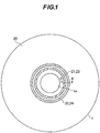
- FIG. 1 is a schematic plan view of an exemplary optical disc on which test data have been recorded by a recording method according to a first embodiment of this invention
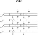
- FIG. 2 is a schematic sectional view through line II-II in FIG. 1 , showing the positional relationships of the test recording areas in each layer.
- first recording layer 11 a second recording layer 12, a third recording layer 13, and a fourth recording layer 14, in order of their distance from the surface (the side facing the optical pickup).
- test data are recorded to determine the optimal recording power for each recording layer, forming test recording areas 21, 22, 23, 24.
- the test recording areas 21, 23 are formed in positions mutually aligned in the thickness direction, both the starting points and the endpoints being aligned in the thickness direction;
- the even-numbered recording layers which may be simply referred to as even-numbered layers below
- the test recording areas 22, 24 are likewise formed in positions mutually aligned in the thickness direction, both the starting points and the endpoints being aligned in the thickness direction.
- test recording areas 21, 23 in the odd-numbered layers and the test recording areas 22, 24 in the even-numbered layers are disposed in mutually non-overlapping positions.
- test recording areas in the odd-numbered and the test recording areas in the even-numbered layers are both formed near the inner edge of the optical disc, that is, near the innermost circumference 1a.
- the areas (facing areas) facing the test recording areas 21, 22, 23, 24, specifically, the areas 31, 32, 33, 34 aligned in the thickness direction and located in the adjacent recording layers, are areas in which test data are not recorded by an optical recording device (non-recording areas).
- the test recording areas 21 to 24 are formed in positions facing the non-recording areas 31 to 34.
- the non-recording areas may be, for example, reproduce-only areas.
- a reproduce-only area includes pits that record, for example, recording conditions for the optical disc such as its recommended write strategy parameters, a recommended asymmetry value, and a recommended wavelength value; the data recorded in the reproduce-only area are usually read before a test recording is made, to determine the conditions of the test recording.
- the reproduce-only areas are formed when the optical disc is manufactured in positions that take the arrangement of test recording areas 21 to 24 (the positions in which test recording areas 21 to 24 will be formed) into consideration so that the reproduce-only areas will face the test recording areas 21 to 24 as described above.
- the area 30 between the test recording areas 21 to 24 and the non-recording areas 31 to 34 is used for recording disc management data, for example.
- the greater part of the optical disc, excluding the non-recording areas 31 to 34, the area 30 for recording management data, and the test recording areas 21 to 24, is a recordable user data area 20.
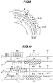
- FIG. 3 is a schematic diagram showing an optical recording device used in recording on the optical disc.
- this optical recording device includes an optical pickup 52 that focuses a laser beam on a selected recording layer (one of the recording layers 11 to 14) of the optical disc 1 and receives the reflected light, a laser driving circuit 55 that supplies laser driving signals to a laser 54 in the optical pickup 52, a servo control circuit 56 that supplies objective lens driving signals to the optical pickup 52, and a central control circuit 58 that controls the laser driving circuit 55 and servo control circuit 56.
- the optical pickup 52 has a laser (a semiconductor laser, for example) 54 that emits a laser beam for recording and reproducing information on the optical disc 1, a collimating lens 61, a beam splitter 62 that passes the laser beam from the laser 54, directs the laser beam onto the optical disc 1, and deflects the light reflected from the optical disc 1 in a predetermined direction, an objective lens 63, a detection lens 64, and a photodetector 65 that converts the reflected light to an electrical signal.
- a laser a semiconductor laser, for example
- the servo control circuit 56 drives the objective lens 63 of the optical pickup 52 to perform tracking control and focusing control according to output from the photodetector 65.
- the laser driving circuit 55 controls the power of the laser beam emitted from the laser 54 by adjusting the level of current supplied to the laser 54.
- the optical recording device also includes a test pattern generating circuit 66, a reproducing circuit 67 that reproduces signals including information detected by the photodetector 65, and a jitter detecting circuit 68 that detects jitter in the reproduced signals output from the reproducing circuit 67.
- a desired recording layer is selected by a focusing control operation using the servo control circuit 56. More specifically, the beam is focused on the desired recording layer.
- a test pattern is output to the laser driving circuit 55 from the test pattern generating circuit 66.
- the laser driving circuit 55 receives a recording power command from the central control circuit 58, and supplies test pattern current to the laser 54 at a level corresponding to the commanded optical power.
- a laser beam corresponding to the test pattern current is emitted from the laser 54, passes through the collimating lens 61, beam splitter 62, and objective lens 63, and is focused so as to illuminate the selected recording layer (one of the recording layers 11, 12, 13, 14) of the optical disc 1, and test data corresponding to the test pattern are recorded in the recording layer.
- the laser driving circuit 55 When the recorded test data are reproduced, the laser driving circuit 55 is given a reproducing power command by the central control circuit 58, and supplies current at a level corresponding to the reproducing power to the laser 54.
- the laser beam emitted from the laser 54 passes through the collimating lens 61, beam splitter 62, and objective lens 63, and is focused to illuminate the selected recording layer (one of the recording layers 11, 12, 13, 14) of the optical disc 1.
- the light reflected from the selected recording layer passes through the objective lens 63, is reflected in the beam splitter 62, passes through the detecting lens 64, is received by the photodetector 65, and is converted to an electrical signal.
- the detected signal from the photodetector 65 is output to the servo control circuit 56 and the reproducing circuit 67.
- the servo control circuit 56 performs tracking control and focusing control according to the detected signal.
- the reproducing circuit 67 decodes and corrects errors in the detected signal, and outputs a reproduced signal.
- the reproduced signal from the reproducing circuit 67 is supplied to the jitter detecting circuit 68, which detects jitter in the reproduced signal.
- the central control circuit 58 includes, for example, a central processing unit (CPU) 58a, a program memory 58b that stores programs executed by the CPU, and a data memory 58c that stores data.
- the programs stored in the program memory 58b include programs for controlling the operations described below.
- the above optical recording device can record not only user data but also test data.
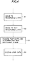
- a test recording is made by using the optical recording device as described below.
- test recording is made before user data are recorded in each recording layer; part of each recording layer is designated as a test recording area. Test recording areas are designated in the alignments shown in FIGs. 1 and 2 .
- step S1 the focal point (the spot of light) is moved to the recording layer in which the recording will be made: for example, the first recording layer 11.
- the central control circuit 58 gives the servo control circuit 56 information designating the target recording layer for focusing control (the tracking target); the servo control circuit 56 moves the objective lens 63 in a direction perpendicular to the recording surface of the optical disc according to this information.
- step S2 the focal point is moved to the test recording area in the recording layer: for example, test recording area 21.
- the central control circuit 58 gives the servo control circuit 56 information (a track address) designating a target track for a seeking and tracking operation; the servo control circuit 56 moves the objective lens 63 in a direction parallel to the recording surface of the optical disc according to this information, and then detects a designated sector by to its sector address.
- step S3 test data are recorded in the test recording area 21, and the optimal recording power is determined by reproducing the signal including the test data.
- Information indicating the optimal recording power is stored in the data memory 58c in the central control circuit 58.
- step S1 to step S3 may be simply referred to as test recording.
- User data are then recorded in the user data area 20 in the recording layer, using the optimal recording power stored in the data memory 58c in step S4.
- step S1 to step S4 The procedure from step S1 to step S4 is also used in the other recording layers, specifically, the second to fourth recording layers 12 to 14: user data are recorded (step S4) after a test recording (steps S1 to S3). Before step S4 (the recording of user data) ends in one recording layer, steps S1 to S3 (test recording) may be carried out in another recording layer.
- a test recording may be made in the second recording layer 12 before the recording of user data in the first recording layer 11 ends, e.g., between the recording of different pieces of user data in the first recording layer 11.
- a test recording may be made in the third recording layer 13 before the recording of user data in the second recording layer 12 ends, e.g., between the recording of different pieces of user data in the first and second recording layers 11 and 12.
- a test recording may be made in the fourth recording layer 14 before the recording of user data in the third recording layer 13 ends, e.g., between the recording of different pieces of user data.
- the interval from when a test recording is made in a recording layer to when the recording of user data starts in that recording layer is preferably short. Most preferably, a test recording is made in a given recording layer just before the start of the recording of user data in that recording layer.
- the test recording areas in which test data are recorded are disposed as described above with reference to FIGs. 1 and 2 .
- the central control circuit 58 designates an area in which test data are to be recorded by a track address and a sector address
- the track address and the sector address are determined so as to give the alignment shown in FIGs. 1 and 2 .
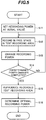
- FIG. 5 shows the details of the processing in step S3 in FIG. 4 , specifically, the process of recording and reproducing test data in the test recording areas, and the determination of the optimal recording power.
- test data are recorded in the test recording area in steps S11 to S14.
- the recorded signal is reproduced in step S15.
- the optimal recording power is then determined according to the reproduced signal in step S16.
- the recording power level is changed during the recording.
- the recording power is decreased in steps. Therefore, the recording power is first set at an initial value (Pi) in step S11, a portion having a predetermined length is specified in the as yet unrecorded part (free space) of the test recording area (the area in which the test data are to be recorded), and test data are recorded in the specified portion in step S12; then the recording power level is changed, e.g., decreased, by a predetermined step width ⁇ P (the resolution of the power determination) in step S13.
- ⁇ P the resolution of the power determination
- step S14 If it is then decided in step S14 that the number of times the recording power level has been changed has not reached a predetermined number, the processing returns to step S12, a portion having the predetermined length is specified in the free space in the test recording area again, and test data are recorded in the specified portion in step S12 at the new power level.
- the processing proceeds to step S15.
- the portion having the predetermined length is specified in the free space in step S12 by specifying a sector address in the free space.
- step S14 whether the recording power level has reached (or been reduced to) a predetermined value may be determined, instead of deciding whether the number of times the recording power level has been changed has reached a predetermined number.
- the initial value is the upper limit (maximum value) Pomax in a range (Rl) considered to be the maximum range of variation of the optimal recording power level due to all possible variations in the optical disk manufacturing process and recording conditions (such as temperature), and the final value is the lower limit (minimum value) Pomin of this range (Rl).
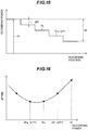
- step S15 the recorded test data are reproduced, the relationship between the value of the recording power and the quality (jitter, for example) of the reproduced signal is found as shown in FIG. 7 , and the recording power generating the reproduced signal of the best quality (minimum jitter) is taken as the optimal recording power in step S16.
- the optimal recording power may be obtained from the relationship between the recording power level and the amplitude of the reproduced signal, instead of the relationship between the recording power level and jitter. This is because disc space in the test recording areas is limited in actual optical disc devices, and because it takes time to find the relationship between the recording power level and jitter.
- the optimal recording power may also be obtained from the relationship between the recording power level and an asymmetry value.
- the optical recording device then includes a reproduced signal amplitude detecting circuit or an asymmetry value detecting circuit instead of the jitter detecting circuit 68 in FIG. 3 .
- test recording areas are disposed in adjacent recording layers in mutually non-overlapping positions in the thickness direction of the optical disc.
- the reason is as follows. Because recordings are made in a test recording area by changing the recording power level from a value smaller than the estimated optimal value to a value greater than the estimated optimal value, the recordings are partly made at a comparatively high recording power level. Because the recording power level is determined individually for each optical disc device, and would be difficult to restrict, there is a strong probability that recording in a test recording area will affect the facing area, specifically, the area located in the adjacent recording layer and aligned in the thickness direction. In order to prevent such effects, the test recording areas in adjacent recording layers are disposed in mutually non-overlapping positions in the thickness direction.
- the recording power illuminates e.g., the third recording layer 13 in FIG. 8
- some of the recording power is also delivered to the second recording layer 12, which is one layer nearer the optical pickup 52.
- the magnitude of the effect produced differs depending on the spacing between the recording layers; a greater spacing enlarges the diameter of the spot of light, lowers the energy density, and reduces the effect.
- the energy density is high enough that the effect cannot be ignored.
- test recording areas in two recording layers such as the first and third recording layers 11 and 13 that are separated by an intervening recording layer are mutually aligned in the thickness direction for the following reason.
- the effect described above on the other recording layer is comparatively small.
- the effect on the first recording layer 11, which is separated by the adjacent second recording layer 12 from the third recording layer 13 on which the light is focused is significantly less than the effect on the second recording layer 12, and can be ignored. This is because the magnitude of the effect decreases in proportion to the second power of the distance between the recording layers.
- test recording areas in all the recording layers in mutually non-overlapping positions could also be considered, but that would give rise to the following problem. For example, if the test recording area 23 in the third recording layer 13 were to be placed in an area facing neither the test recording area 21 in the first recording layer 11 nor the test recording area 22 in the second recording layer 12, the total area facing the test recording areas would be increased, and since this facing area is unsuited for the recording of normal user data, the usage efficiency of the recording areas would be reduced.
- test recording areas were to be disposed in positions facing a reproduce-only area
- the structure of the recording layers of the optical disc would vary from one recording layer to another, making the optical disc manufacturing process more complicated.
- addressing programs used in the recording and reproducing device for test recording and for the recording of user data would become more complex.
- the test recording area 23 in the third recording layer 13 and the test recording area 21 in the first recording layer 11 are disposed in positions aligned in the thickness direction, both facing the same area in the other layers.
- no additional area in the other layers faces a test recording area, and the identical alignment of areas in the third recording layer 13 and the first recording layer 11, simplifies the optical disc manufacturing process and the programming of the recording and reproducing device.
- test recording area 24 in the fourth recording layer 14 and the test recording area 22 in the second recording layer 12 are disposed in positions aligned in the thickness direction, so that there is no new additional area facing the test recording area 24 in the fourth recording layer 14.
- the identical alignment of the fourth recording layer 14 and the second recording layer 12 also simplifies the optical disc manufacturing process and the program in the recording and reproducing device.
- test recording areas in the odd-numbered recording layers may be similarly formed in positions mutually aligned in the thickness direction, and the test recording areas in the even-numbered recording layers may be formed in positions mutually aligned in the thickness direction.
- test recording areas 21 to 24 are formed in positions facing non-recording areas 31 to 34, the following effects are obtained. More specifically, if the test recording areas in mutually adjacent layers were to overlap, a test recording made in one layer might affect the facing test area, so that when a test recording was made in the facing test area later, it might not be possible to carry out an accurate test. This problem is solved by placing a non-recording area such as a reproduce-only area, which is not affected by the recording power, in a position facing each test recording area.
- FIG. 9 is an enlarged plan view of a central region of an optical disc, similar to FIG. 1
- FIG. 10 is a schematic sectional view through line X-X in FIG. 9 , similar to FIG. 2 .
- the optical disc in FIGs. 9 and 10 is similar to the optical disc in FIGs. 1 and 2 .
- reproduce-only areas 41 and 43 in the odd-numbered recording layers 11 and 13 are formed in positions mutually aligned in the thickness direction
- reproduce-only areas 42 and 44 in the even-numbered recording layers 12 and 14 are formed in positions mutually aligned in the thickness direction
- parts 41a and 43a of the reproduce-only areas 41 and 43 in the odd-numbered recording layers 11 and 13 are formed in positions that do not overlap at least parts 42a and 44a of the reproduce-only areas 42 and 44 in the even-numbered recording layers 12 and 14 in the thickness direction of the optical disc.
- test recording areas 22 and 24 in the even-numbered recording layers 12 and 14 are formed in positions facing parts 41b and 43b of these parts 41a and 43a of the reproduce-only areas 41 and 43 in the odd-numbered recording layers 11 and 13, and the test recording areas 21 and 23 in the odd-numbered recording layers 11 and 13 are formed in positions facing parts 42b and 44b of parts 42a and 44a of the reproduce-only areas 42 and 44 in the even-numbered recording layers 12 and 14.
- test recording areas 22 and 24 in the even-numbered recording layers 12 and 14 may be formed in positions facing all of parts 41a and 43a of the reproduce-only areas 41 and 43 in the odd-numbered recording layers 11 and 13, and the test recording areas 21 and 23 in the odd-numbered recording layers 11 and 13 may be formed in positions facing all of parts 42a and 44a of the reproduce-only areas 42 and 44 in the even-numbered recording layers 12 and 14.
- the optical disc shown in FIGs. 9 and 10 In order to form the optical disc shown in FIGs. 9 and 10 , first, an optical disc in which the reproduce-only areas 41 to 44 are formed as shown in FIGs. 9 and 10 is obtained. Next, in the recording layers 11 to 14, the test recording areas 21 to 24 are formed in positions shown in FIGs. 9 and 10 by making a test recording in each recording layer as in the procedure described above.
- the non-recording areas 31 to 34 facing the test recording areas 21 to 24 are reproduce-only areas, but the non-recording areas 31 to 34 need not be reproduce-only areas. If the test recording areas face reproduce-only areas, recording and reproducing in the test recording areas may be affected by pits in the reproduce-only areas; this problem is solved by placing the reproduce-only areas in areas not facing the test recording areas, and using the areas facing the test recording areas as non-recording areas that are not reproduce-only areas.
- FIGs. 11 and 12 An example of such an alignment of recording areas is shown in FIGs. 11 and 12 .
- FIG. 11 is a plan view, similar to FIG. 1
- FIG. 12 is a schematic sectional view through line XII-XII in FIG. 11 , similar to FIG. 2 .
- the optical disc in FIGs. 11 and 12 is similar to the optical disc in FIGs. 1 and 2 .
- the areas 31 to 34 facing the test recording areas 21 to 24 are non-recording areas that are not reproduce-only areas, and reproduce-only areas 41 to 44 are formed in positions outward of and adjacent to the test recording areas 21 to 24 and the facing areas 31 to 34.
- the recording device reads recording conditions from the reproduce-only area (one of the reproduce-only areas 41 to 44) in the same recording layer, then moves the focal point of the optical pickup to the test recording area, and makes the test recording. Recording conditions for the test recording, or at least the initial values used in the test recording, are set according to the recording conditions read from the reproduce-only area.
- an advantage is that after the processing for reading of the recording conditions is carried out, the distance traveled by the focal point to the area that records test data can be shortened, so the time required for a test recording can also be shortened.
- FIG. 13 is a schematic plan view of an exemplary optical disc on which test data have been recorded by a recording method according to a second embodiment of this invention.
- the optical disc 2 shown in FIG. 13 four recording layers are formed: a first recording layer 11, a second recording layer 12, a third recording layer 13, and a fourth recording layer 14, in order of their distance from the surface, similar to the optical disc 1 in FIGs. 1 and 2 .
- the first, second, third, and fourth recording layers 11, 12, 13, 14, test recording areas 21, 22, 23, 24 for determining the optimal recording power for each recording layer are formed.
- the test recording areas in the odd-numbered layers and the even-numbered layers are all formed near the inner edge of the optical disc 1, that is, near the innermost circumference 1a, but in the second embodiment, although the test recording areas 21 and 23 in the odd-numbered layers 11 and 13 are located near the inner edge, that is, near the innermost circumference 1a, the test recording areas 22 and 24 in the even-numbered layers 12 and 14 are disposed near the outer edge, that is, near the outermost circumference 1b.
- test recording area 21 in the first recording layer 11 is formed near the inner edge, for example, a recording in the first recording layer 11 starts near the inner edge; a test recording is made in the test recording area near the inner edge; then user data are recorded sequentially from the inner edge toward the outer edge, and the recording in the first recording layer 11 ends near the outer edge.
- the focal point has to be moved from the first recording layer 11 to the second recording layer 12. If the test recording area 22 in the second recording layer 12 were to be formed near the inner edge, the focal point would have to be moved from the outer edge to the inner edge, requiring extra access time.
- test recording area 22 is formed near the outer edge as in the second embodiment, such travel of the focal point in the second recording layer 12 (until it reaches the test recording area 22) is unnecessary; when the recording in the first recording layer 11 ends, the focal point is near the outer edge, so it only has to be moved from the first recording layer 11 to the second recording layer; a test recording is made in the test recording area 22 near the outer edge; then user data are recorded, proceeding from the outer edge toward the inner edge. The time for a test recording can accordingly be shortened.
- the focal point is near the inner edge of the optical disc, and when the focal point is moved from the second recording layer 12 to the third recording layer 13 to start recording in the third recording layer 13, since the test recording area 23 is formed near the inner edge, no movement of the focal point in the third recording layer 13 is necessary, so the time for the test recording can be shortened.
- the focal point is near the outer edge of the optical disc, and when the focal point is moved from the third recording layer 13 to the fourth recording layer 14 to start recording in the fourth recording layer 14, since the test recording area 24 is formed near the outer edge, no movement of the focal point in the fourth recording layer 14 is necessary, so the time for the test recording can also be shortened.
- test recording can thus be shortened because the test recording areas 21 and 23 in the odd-numbered first and third recording layers 11 and 13 are formed near the inner edge and the test recording areas 22 and 24 in the even-numbered second and fourth recording layers are formed near the outer edge, as described above.
- test recording areas 21 and 23 in the odd-numbered first and third recording layers 11 and 13 may be formed near the outer edge and the test recording areas 22 and 24 in the even-numbered second and fourth recording layers may be formed near the inner edge; a similar effect is also obtained in this case.
- FIG. 14 is a schematic plan view of an exemplary optical disc on which test data have been recorded by a recording method according to a third embodiment of this invention.
- the optical disc 2 shown in FIG. 14 four recording layers are formed: a first recording layer 11, a second recording layer 12, a third recording layer 13, and a fourth recording layer 14, in order of their distance from the surface, similar to the optical disc 1 in FIGs. 1 and 2 and the optical disc in FIG. 13 .
- the optical disc 2 in FIG. 14 differs from the optical disc 1 in FIGs. 1 and 2 and the optical disc 2 in FIG. 13 by having test recording areas near both the inner edge, that is, the innermost circumference 1a, and the outer edge, that is, the outermost circumference 1b, in each recording layer.
- the first recording layer 11 has a test recording area 21A near the inner edge, and a test recording area 21B near the outer edge.
- the second, third, and fourth recording layers 12, 13, 14 have test recording areas 22A, 23A, 24A near the inner edge, and test recording areas 22B, 23B, 24B near the outer edge, respectively.
- test recording areas in each layer near both the inner edge and the outer edge is as follows.
- the optical disc When recording on the optical disc is performed at high speed, in order to obtain the same linear velocity, the optical disc has to be rotated near the inner edge almost twice as fast as near the outer edge, but this often exceeds the limit within which the disc motor can be used.
- the optimal recording power obtained by making test recordings in a test recording area near the inner edge may be inappropriate for use in recording user data near the outer edge.
- the optimal recording power obtained by making test recordings in a test recording area near the outer edge may also be inappropriate for use in recording user data near the inner edge.
- This problem is solved by forming test recording areas near both the inner edge and the outer edge, as shown in FIG. 14 , and determining the optimal recording power by using both the optimal recording power obtained by making test recordings in the test recording area near the inner edge and the optimal recording power obtained by making test recordings in the test recording area near the outer edge, together with the radial position at which the user data are recorded.
- the optimal recording power obtained by making test recordings in the test recording area near the inner edge may be used for recording user data near the inner edge, specifically, inward of a predetermined position in the radial direction, e.g., the midpoint position
- the optimal recording power obtained by making test recordings in the test recording area near the outer edge may be used for recording user data near the outer edge, specifically, outward of a predetermined position in the radial direction, e.g., the midpoint position.
- user data may be recorded by using a recording power obtained by taking a weighted average of the optimal recording power obtained by making test recordings in the test recording area near the inner edge and the optimal recording power obtained by making test recordings in the test recording area near the outer edge, weighted according to the recording position of the user data (the radial position).
- test recordings can be made by a differing procedure described below, instead of the procedure in the first embodiment.
- test recordings in each recording layer are made in a sequence of operations in which, in the recording of the test data, the recording power level is changed (step S13 in FIG. 5 ) in steps of a width set at a value necessary for determining the optimal recording power with sufficient accuracy, but the procedure described above may be performed in plurality of stages.
- the first stage is, as it were, a coarse adjustment: test data are recorded at a plurality of recording power values differing by a first predetermined step width in a test recording area, the recorded test data are reproduced, and an approximate value of the optimal recording power is determined by evaluating the reproduction results.
- the second stage is, as it were, a fine adjustment: test data are recorded at a plurality of recording power values in a range near the approximate value of the optimal recording power, differing by a second predetermined step width smaller than the first predetermined step width in the test recording area, the recorded test data are reproduced, and a more precise value of the optimal recording power is determined by evaluating the reproduction results.
- the recording power level is changed in steps of a comparatively large width throughout a range (a maximum range) considered to include all possible values of the optimal recording power level despite variations in the optical disk manufacturing process and recording conditions (such as temperature), and a range around the approximate value of the optimal recording power, i.e., a range determined to include the optimal recording power, is obtained under the current recording conditions for each recording layer in the currently used optical disc.
- the recording power level is changed in steps of a comparatively small width in the range determined to include the optimal recording power, and the optimal recording power is obtained.
- the recording power level is changed in steps of a comparatively large width ⁇ P1, and the optimal value Po is found to be included in the range from a recording power Pq to a recording power (Pq - ⁇ P1), as shown in FIGs. 15 and 16 .
- the recording power level is changed in steps of a width ⁇ P2 smaller than step width ⁇ P1 in the range from recording power Pq to recording power (Pq - ⁇ P1), and the optimal value Po is determined.
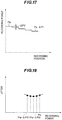
- FIGs. 19 and 20 are flowcharts showing the processes described above.
- the process of the coarse adjustment shown in FIG. 19 is broadly the same as the process in FIG. 5 , steps S21 to S27 corresponding to steps S11 to S17, respectively, but the step width by which the recording power is changed in step S23 is larger than the step width in step S13.
- the optimal recording power is not determined as in step S16; instead, a process for determining a range that includes the optimal recording power is performed.
- step S31 in which whether the predetermined changes of the recording power level have been completed is decided, whether the recording power level has reached the lower limit in the range determined in step S26 is determined.
- the fine adjustment may be performed at once after the coarse adjustment ends, or after the coarse adjustment and another procedure end.
- an optical disc has a plurality of recording layers, e.g., two recording layers, and user data are recorded first in one of the recording layers (the first recording layer), then in the other recording layer (the second recording layer), before the recording of user data starts in the first recording layer, a test recording may be made in the first recording layer and the first-stage test recording (the coarse adjustment) described above may be made in the second recording layer; then, after the recording of user data ends in the first recording layer and before the recording of user data starts in the second recording layer, the second-stage procedure (the fine adjustment) described above may be performed.
- the first-stage test recording the coarse adjustment
- the interval from when the recording of user data ends in the first recording layer to when the recording of user data starts in the second recording layer is preferably short.
- recording conditions such as temperature
- the fine adjustment is performed in a given recording layer just before the start of the recording of user data in that recording layer.
- the first-stage process (the coarse adjustment) may be performed in the second recording layer either before or after the test recording in the first recording layer.
- the test recording in the first recording layer may be made in two stages, or in one stage as described with reference to FIG. 5 .
- the coarse adjustment may be performed in the second recording layer during the suspension.
- the time from the end of the recording of user data in the first recording layer to the start of recording of user data in the second recording layer can be shortened because only the fine adjustment is required in the second recording layer.
- test recordings may be made in several or all of the recording layers in an optical disc before the recording of user data starts in any of those recording layers.
- test data may be recorded (steps S11 to S14) in another recording layer, or after test data are recorded in a plurality of recording layers (steps S11 to S14), the test data may be reproduced in succession in the plurality of recording layers (step S15), and the optimal recording powers may be determined (step S16) in the plurality of recording layers.
- the recording of user data starts after test recordings have been made in a plurality of recording layers as described above, when a continuous recording spans one recording layer (the first recording layer) and another recording layer (the second recording layer), an advantage is that the recording of user data starts in the second recording layer immediately after the recording of user data ends in the first recording layer (because no test recording is necessary).
- a recording device may include a control input means for making a selection, so that a user can make a selection by operating the control input means.
- test recordings are made before user data are recorded in a plurality of recording layers as described above, if the test recording areas in all recording layers are formed near the inner edge of the optical disc as shown in FIGs. 1 and 2 , or alternatively, if the test recording areas in all recording layers are formed near the outer edge of the optical disc, then the focal point remains located near the inner edge or the outer edge and only has to be moved between recording layers, with the effect of shortening the test recording time.
- first to fifth embodiments have been described as making a test recording before user data are recorded in each recording layer and recording user data in the recording layer at the optimal recording power thereby determined, this does not necessarily mean that the same recording power has to be used across all of the recording layer; during the recording of user data in each recording layer, temperature variations etc. may be detected and the power may be adjusted accordingly.
- a test recording may be made, for example, and a newly determined optimal recording power may be used for recording subsequent user data.
- the condition for making a new test recording in each recording layer as described above may be a temperature change greater than or equal to a predetermined value, or a lapse of at least a predetermined time from the previous test recording.
- step S4 Even when the recording of user data (step S4) starts after test recordings (steps S1 to S3) have been made in several or all of the recording layers in the optical disc as described in the fifth embodiment, for example, if the recording of user data is suspended during the recording of user data in one recording layer, a test recording may be made, and a newly determined optimal recording power may used for the subsequent recording of user data in that one recording layer; in this case, when the recording of user data ends in the one recording layer and begins in a new recording layer, the recording of user data in the new recording layer may start at a recording power level determined from the recording power level that was used at the conclusion of the recording of user data in the previous recording layer and the ratio between the respective optimal recording power levels obtained for the two recording layers when test recordings were first made in the plurality of recording layers.
- the optimal recording power levels in the first and second recording layers are determined as Pola and Po2a.
- the recording of user data then starts in the first recording layer with use of recording power Pola, but the recording is discontinued and a new test recording is made, yielding a new optimal recording power Polb.
- the subsequent recording in the first recording layer is made with use of this optimal recording power Polb, so the optimal recording power in use at the conclusion of the recording of user data in the first recording layer is Polb.
- the ratio between the respective optimal recording power levels obtained for the two recording layers when test recordings were first made in the plurality of the recording layers is Po2a/Pola.
- an advantage is that the recording of user data starts in the second recording layer immediately after the recording of user data ends in the first recording layer (because no test recording is necessary).
- test recordings may be made again in both the one recording layer and the next recording layer, while if the suspension time during the recording of user data in the one recording layer is comparatively short and does not provide sufficient length to make test recordings in both recording layers, but does provide sufficient length to make a test recording in the one recording layer, a test recording may be made again in only the one recording layer.
- the recording of user data may then start in the next recording layer at a power level determined by use of the recording power that was used at the conclusion of the recording of user data in the one recording layer and the ratio between the optimal recording power levels obtained for the two recording layers when the last simultaneous test recordings were made in the two recording layers.
- whether to make the recording as described above may be selected by the user by operating a control input means.
Landscapes
- Physics & Mathematics (AREA)
- Optics & Photonics (AREA)
- Optical Recording Or Reproduction (AREA)
- Optical Head (AREA)
Applications Claiming Priority (3)
| Application Number | Priority Date | Filing Date | Title |
|---|---|---|---|
| JP2004099616A JP2005285254A (ja) | 2004-03-30 | 2004-03-30 | 光ディスクの記録方法及び光ディスク |
| PCT/JP2004/012089 WO2005101381A1 (ja) | 2004-03-30 | 2004-08-24 | 光ディスクの記録方法及び光ディスク |
| EP04772050.3A EP1732066B1 (en) | 2004-03-30 | 2004-08-24 | Optical disc recording method and optical disc |
Related Parent Applications (2)
| Application Number | Title | Priority Date | Filing Date |
|---|---|---|---|
| EP04772050.3A Division-Into EP1732066B1 (en) | 2004-03-30 | 2004-08-24 | Optical disc recording method and optical disc |
| EP04772050.3A Division EP1732066B1 (en) | 2004-03-30 | 2004-08-24 | Optical disc recording method and optical disc |
Publications (1)
| Publication Number | Publication Date |
|---|---|
| EP3522162A2 true EP3522162A2 (en) | 2019-08-07 |
Family
ID=35150218
Family Applications (3)
| Application Number | Title | Priority Date | Filing Date |
|---|---|---|---|
| EP04772050.3A Expired - Fee Related EP1732066B1 (en) | 2004-03-30 | 2004-08-24 | Optical disc recording method and optical disc |
| EP19161383.5A Withdrawn EP3522162A2 (en) | 2004-03-30 | 2004-08-24 | Optical disc recording method and optical disc |
| EP08012207.0A Expired - Fee Related EP1978511B1 (en) | 2004-03-30 | 2004-08-24 | Optical disc recording method and optical disc |
Family Applications Before (1)
| Application Number | Title | Priority Date | Filing Date |
|---|---|---|---|
| EP04772050.3A Expired - Fee Related EP1732066B1 (en) | 2004-03-30 | 2004-08-24 | Optical disc recording method and optical disc |
Family Applications After (1)
| Application Number | Title | Priority Date | Filing Date |
|---|---|---|---|
| EP08012207.0A Expired - Fee Related EP1978511B1 (en) | 2004-03-30 | 2004-08-24 | Optical disc recording method and optical disc |
Country Status (6)
| Country | Link |
|---|---|
| US (3) | US7660217B2 (ko) |
| EP (3) | EP1732066B1 (ko) |
| JP (1) | JP2005285254A (ko) |
| KR (2) | KR100800905B1 (ko) |
| TW (1) | TWI277073B (ko) |
| WO (1) | WO2005101381A1 (ko) |
Families Citing this family (18)
| Publication number | Priority date | Publication date | Assignee | Title |
|---|---|---|---|---|
| AU8620901A (en) * | 2000-09-13 | 2002-03-26 | Matsushita Electric Ind Co Ltd | Optical information recording medium and optical information recording method, optical information recording device |
| MY142139A (en) | 2003-06-28 | 2010-09-30 | Samsung Electronics Co Ltd | Information storage medium |
| US7518962B2 (en) | 2003-06-28 | 2009-04-14 | Samsung Electronics Co., Ltd. | Method of recording and/or reproducing data with respect to a multi-layer information storage medium having optimal power control areas |
| JP2005285254A (ja) * | 2004-03-30 | 2005-10-13 | Mitsubishi Electric Corp | 光ディスクの記録方法及び光ディスク |
| WO2006028115A1 (ja) * | 2004-09-09 | 2006-03-16 | Pioneer Corporation | 情報記録媒体、情報記録装置及び方法、並びにコンピュータプログラム |
| KR20060082513A (ko) * | 2005-01-12 | 2006-07-19 | 엘지전자 주식회사 | 기록매체 및 기록매체의 기록방법과 기록장치 |
| TW200627397A (en) | 2005-01-12 | 2006-08-01 | Victor Company Of Japan | Optical-disc drive apparatus and method of deciding optimum recording powers of laser beam |
| KR20070003511A (ko) * | 2005-06-30 | 2007-01-05 | 엘지전자 주식회사 | 기록매체 및 기록매체 기록/재생방법 및 장치 |
| JP4919790B2 (ja) | 2006-12-15 | 2012-04-18 | シャープ株式会社 | 波長制御方法、ホログラム情報処理装置およびホログラム記録媒体 |
| JP4810519B2 (ja) * | 2007-09-14 | 2011-11-09 | 株式会社リコー | 多層式追記型光記録媒体及びその記録方法、記録装置 |
| US8125725B1 (en) | 2007-10-15 | 2012-02-28 | Marvell International Ltd. | Recording medium and recording apparatus for using test data recorded in a blank zone to refine data recording |
| JP4381456B2 (ja) * | 2008-03-26 | 2009-12-09 | 株式会社東芝 | 光ディスク装置及び光ディスク記録再生方法 |
| JP2010009685A (ja) * | 2008-06-27 | 2010-01-14 | Sony Corp | 多層光記録媒体、記録装置、記録レーザパワー調整方法 |
| KR20110027788A (ko) * | 2008-08-07 | 2011-03-16 | 파나소닉 주식회사 | 정보 기록 매체 및 정보 기록 장치 |
| MY152449A (en) * | 2008-09-29 | 2014-09-30 | Panasonic Corp | Information recording medium, recording method, and reproducing method |
| WO2010052820A1 (ja) * | 2008-11-04 | 2010-05-14 | パナソニック株式会社 | 情報記録媒体、記録方法および再生方法 |
| WO2010093212A2 (ko) | 2009-02-13 | 2010-08-19 | 삼성전자 주식회사 | 정보 저장 매체, 기록 재생 장치 및 기록 재생 방법 |
| JP6035840B2 (ja) * | 2012-04-23 | 2016-11-30 | ソニー株式会社 | 記録装置、記録方法、記録媒体 |
Citations (1)
| Publication number | Priority date | Publication date | Assignee | Title |
|---|---|---|---|---|
| JP2000311346A (ja) | 1999-04-26 | 2000-11-07 | Ricoh Co Ltd | 光ディスク記録再生装置と光ディスクの最適記録パワー値決定方法 |
Family Cites Families (30)
| Publication number | Priority date | Publication date | Assignee | Title |
|---|---|---|---|---|
| JPH05225571A (ja) * | 1992-02-14 | 1993-09-03 | Sony Corp | 光ディスク記録装置およびその方法 |
| JP3551662B2 (ja) | 1996-10-23 | 2004-08-11 | 日本ビクター株式会社 | 光ディスク再生装置及び光ディスク再生装置の再生信号の最適化方法 |
| JPH113550A (ja) * | 1997-06-12 | 1999-01-06 | Nikon Corp | 情報記録再生装置 |
| JPH11232681A (ja) * | 1998-02-13 | 1999-08-27 | Fujitsu Ltd | 光学的情報記憶装置 |
| KR100288783B1 (ko) * | 1998-09-18 | 2001-05-02 | 구자홍 | 광기록매체의 기록 광파워 검출저장 및 이를 이용한 기록 광파워 조절장치와 그 방법 |
| JP2000195054A (ja) | 1998-12-24 | 2000-07-14 | Ricoh Co Ltd | 光学的情報記録再生装置 |
| EE04789B1 (et) | 1999-01-08 | 2007-02-15 | Koninklijke Philips Electronics N.V. | Meetod optimaalse kirjutus- ja kustutusvõimsuse kindlaksmääramiseks optilisele salvestuskandjale kantud märgiste tegemiseks ning kustutamiseks ja salvestusseade |
| JP2001307326A (ja) | 2000-04-20 | 2001-11-02 | Teac Corp | 光ディスク記録装置 |
| AU8620901A (en) | 2000-09-13 | 2002-03-26 | Matsushita Electric Ind Co Ltd | Optical information recording medium and optical information recording method, optical information recording device |
| JP2002117542A (ja) * | 2000-10-05 | 2002-04-19 | Pioneer Electronic Corp | 多層回転記録媒体及びその記録再生方法並びに記録再生装置 |
| JP2002197653A (ja) * | 2000-12-22 | 2002-07-12 | Sharp Corp | 光ディスク装置および光ディスク装置のレーザパワー調整方法 |
| KR100438828B1 (ko) | 2001-11-08 | 2004-07-05 | 삼성전자주식회사 | 칩 상의 전기적 미세 검출기 |
| JP2003168216A (ja) * | 2001-11-29 | 2003-06-13 | Sony Corp | 光記録媒体、並びに、光記録媒体に対する記録装置及び方法 |
| CN101281769B (zh) * | 2002-01-22 | 2013-11-06 | 松下电器产业株式会社 | 多层信息记录媒介,信息记录设备,和记录方法 |
| JP4101666B2 (ja) * | 2002-01-22 | 2008-06-18 | 松下電器産業株式会社 | 情報記録媒体、記録装置、再生装置、記録方法、再生方法 |
| JP2003288759A (ja) * | 2002-01-22 | 2003-10-10 | Matsushita Electric Ind Co Ltd | 多層情報記録媒体、記録装置および記録方法 |
| JP3867962B2 (ja) | 2002-03-05 | 2007-01-17 | 株式会社リコー | 記録条件決定プログラム及び記録媒体、記録条件決定方法並びに情報記録装置 |
| JP3956743B2 (ja) * | 2002-04-01 | 2007-08-08 | ティアック株式会社 | 光ディスク装置 |
| JP4295474B2 (ja) | 2002-05-24 | 2009-07-15 | ソニー株式会社 | ディスク記録媒体、ディスクドライブ装置、ディスク製造方法 |
| JP2004063035A (ja) * | 2002-07-31 | 2004-02-26 | Nec Corp | 光ディスク用パワーキャリブレーション方法及び装置 |
| JP4322105B2 (ja) | 2002-12-20 | 2009-08-26 | 三菱化学メディア株式会社 | 光記録媒体の記録方法及び記録装置 |
| JP2004206803A (ja) * | 2002-12-25 | 2004-07-22 | Teac Corp | 光ディスク装置 |
| JP2004295940A (ja) * | 2003-03-25 | 2004-10-21 | Ricoh Co Ltd | 試し書き処理制御方法、光記録媒体、光情報記録装置、光情報記録用プログラム及び記憶媒体 |
| JP2004335052A (ja) * | 2003-05-12 | 2004-11-25 | Ricoh Co Ltd | 信号調整方法、位置制御方法、プログラム及び記録媒体、並びに光ディスク装置 |
| KR100677108B1 (ko) | 2003-06-12 | 2007-02-01 | 삼성전자주식회사 | 정보 저장매체 |
| CN1757062B (zh) * | 2003-06-12 | 2011-11-09 | 三星电子株式会社 | 设置信息存储介质的区的方法 |
| US7286454B2 (en) | 2003-06-30 | 2007-10-23 | Samsung Electronics Co., Ltd. | Information storage medium |
| JP4319521B2 (ja) * | 2003-10-31 | 2009-08-26 | パイオニア株式会社 | 光記録装置および収差補正方法 |
| JP2005228410A (ja) * | 2004-02-13 | 2005-08-25 | Pioneer Electronic Corp | 情報記録装置及び方法、並びにコンピュータプログラム |
| JP2005285254A (ja) * | 2004-03-30 | 2005-10-13 | Mitsubishi Electric Corp | 光ディスクの記録方法及び光ディスク |
-
2004
- 2004-03-30 JP JP2004099616A patent/JP2005285254A/ja active Pending
- 2004-08-24 EP EP04772050.3A patent/EP1732066B1/en not_active Expired - Fee Related
- 2004-08-24 KR KR1020077021027A patent/KR100800905B1/ko active IP Right Grant
- 2004-08-24 KR KR1020067020038A patent/KR100800906B1/ko active IP Right Grant
- 2004-08-24 EP EP19161383.5A patent/EP3522162A2/en not_active Withdrawn
- 2004-08-24 US US10/587,913 patent/US7660217B2/en not_active Expired - Fee Related
- 2004-08-24 WO PCT/JP2004/012089 patent/WO2005101381A1/ja not_active Application Discontinuation
- 2004-08-24 EP EP08012207.0A patent/EP1978511B1/en not_active Expired - Fee Related
- 2004-09-13 TW TW093127628A patent/TWI277073B/zh not_active IP Right Cessation
-
2008
- 2008-07-30 US US12/182,735 patent/US7969840B2/en not_active Expired - Fee Related
-
2009
- 2009-07-13 US US12/501,845 patent/US8004943B2/en not_active Expired - Fee Related
Patent Citations (1)
| Publication number | Priority date | Publication date | Assignee | Title |
|---|---|---|---|---|
| JP2000311346A (ja) | 1999-04-26 | 2000-11-07 | Ricoh Co Ltd | 光ディスク記録再生装置と光ディスクの最適記録パワー値決定方法 |
Also Published As
| Publication number | Publication date |
|---|---|
| US7660217B2 (en) | 2010-02-09 |
| US20070159942A1 (en) | 2007-07-12 |
| EP1978511A3 (en) | 2009-07-22 |
| EP1732066B1 (en) | 2019-05-22 |
| EP1978511B1 (en) | 2019-05-29 |
| EP1732066A1 (en) | 2006-12-13 |
| WO2005101381A1 (ja) | 2005-10-27 |
| US7969840B2 (en) | 2011-06-28 |
| EP1978511A2 (en) | 2008-10-08 |
| KR100800906B1 (ko) | 2008-02-04 |
| KR20070005650A (ko) | 2007-01-10 |
| KR100800905B1 (ko) | 2008-02-04 |
| JP2005285254A (ja) | 2005-10-13 |
| TWI277073B (en) | 2007-03-21 |
| EP1732066A4 (en) | 2008-04-30 |
| TW200532671A (en) | 2005-10-01 |
| US20080291798A1 (en) | 2008-11-27 |
| US8004943B2 (en) | 2011-08-23 |
| KR20070102624A (ko) | 2007-10-18 |
| US20100014401A1 (en) | 2010-01-21 |
Similar Documents
| Publication | Publication Date | Title |
|---|---|---|
| US7969840B2 (en) | Recording method for optimizing an optimal recording power | |
| KR100937369B1 (ko) | 기록 장치 및 기록 방법 | |
| EP2148330B1 (en) | Optical information recording medium, optical information recording method, and optical information recording apparatus | |
| EP1607947B1 (en) | Method for controlling trial write onto optical recording medium | |
| JP3772136B2 (ja) | 光ディスク装置と光ディスク装置のアクセス方法 | |
| EP1176586A2 (en) | Information recording medium with index header | |
| US20110096656A1 (en) | Multi-Layer Optical Disc, And Recording Method And Apparatus For Multi-Layer Optical Disc | |
| KR20040018942A (ko) | 광 디스크 장치 | |
| US20050276212A1 (en) | Information record medium, and information record apparatus and method | |
| JP2008516367A (ja) | 光記録担体 | |
| US20080298181A1 (en) | Optical disc apparatus and optical disc apparatus control method | |
| JP4361543B2 (ja) | 光ディスク | |
| US20050018582A1 (en) | Optical disk and optical disk apparatus | |
| US20080074972A1 (en) | Information Recording Medium, Information Recording Device and Method and Computer Program | |
| US20070230308A1 (en) | Multilayer Information Recording Medium, Information Recorder, and Information Reproducer | |
| JP4287471B2 (ja) | 光ディスク装置および光ディスク装置の集積回路 | |
| US20060077803A1 (en) | Method of adjusting a writing focus in an optical disc drive | |
| JP2007184025A (ja) | 光ディスク記録方法および光ディスク装置 | |
| JP4328877B2 (ja) | 情報記録再生装置、情報記録再生方法及びフォーカス位置調整プログラム | |
| KR100662592B1 (ko) | 광 디스크 장치 및 그 제어 방법 | |
| JPWO2008096629A1 (ja) | 光照射パワー調整方法及び光学的情報記録再生装置 | |
| JPWO2006126575A1 (ja) | パラメータ調整方法及び情報記録/再生装置。 | |
| JP2006323978A (ja) | 情報記録/再生方法および情報記録/再生装置 | |
| JP2003016642A (ja) | 光ディスク装置、光ディスク媒体および光ディスクの読み取りまたは書き込み方法 | |
| JP2002329337A (ja) | 光情報記録装置 |
Legal Events
| Date | Code | Title | Description |
|---|---|---|---|
| PUAI | Public reference made under article 153(3) epc to a published international application that has entered the european phase |
Free format text: ORIGINAL CODE: 0009012 |
|
| STAA | Information on the status of an ep patent application or granted ep patent |
Free format text: STATUS: REQUEST FOR EXAMINATION WAS MADE |
|
| 17P | Request for examination filed |
Effective date: 20190517 |
|
| AC | Divisional application: reference to earlier application |
Ref document number: 1732066 Country of ref document: EP Kind code of ref document: P |
|
| AK | Designated contracting states |
Kind code of ref document: A2 Designated state(s): DE GB |
|
| STAA | Information on the status of an ep patent application or granted ep patent |
Free format text: STATUS: THE APPLICATION IS DEEMED TO BE WITHDRAWN |
|
| 18D | Application deemed to be withdrawn |
Effective date: 20200303 |