EP3521625B1 - Gasförmige fluidverdichtungsvorrichtung - Google Patents
Gasförmige fluidverdichtungsvorrichtung Download PDFInfo
- Publication number
- EP3521625B1 EP3521625B1 EP17856570.1A EP17856570A EP3521625B1 EP 3521625 B1 EP3521625 B1 EP 3521625B1 EP 17856570 A EP17856570 A EP 17856570A EP 3521625 B1 EP3521625 B1 EP 3521625B1
- Authority
- EP
- European Patent Office
- Prior art keywords
- sliding element
- wall
- housing
- pin
- orbiter
- Prior art date
- Legal status (The legal status is an assumption and is not a legal conclusion. Google has not performed a legal analysis and makes no representation as to the accuracy of the status listed.)
- Active
Links
Images



Classifications
-
- F—MECHANICAL ENGINEERING; LIGHTING; HEATING; WEAPONS; BLASTING
- F04—POSITIVE - DISPLACEMENT MACHINES FOR LIQUIDS; PUMPS FOR LIQUIDS OR ELASTIC FLUIDS
- F04C—ROTARY-PISTON, OR OSCILLATING-PISTON, POSITIVE-DISPLACEMENT MACHINES FOR LIQUIDS; ROTARY-PISTON, OR OSCILLATING-PISTON, POSITIVE-DISPLACEMENT PUMPS
- F04C2/00—Rotary-piston machines or pumps
- F04C2/02—Rotary-piston machines or pumps of arcuate-engagement type, i.e. with circular translatory movement of co-operating members, each member having the same number of teeth or tooth-equivalents
- F04C2/025—Rotary-piston machines or pumps of arcuate-engagement type, i.e. with circular translatory movement of co-operating members, each member having the same number of teeth or tooth-equivalents the moving and the stationary member having co-operating elements in spiral form
-
- B—PERFORMING OPERATIONS; TRANSPORTING
- B60—VEHICLES IN GENERAL
- B60H—ARRANGEMENTS OF HEATING, COOLING, VENTILATING OR OTHER AIR-TREATING DEVICES SPECIALLY ADAPTED FOR PASSENGER OR GOODS SPACES OF VEHICLES
- B60H1/00—Heating, cooling or ventilating devices
- B60H1/32—Cooling devices
- B60H1/3204—Cooling devices using compression
- B60H1/3223—Cooling devices using compression characterised by the arrangement or type of the compressor
-
- F—MECHANICAL ENGINEERING; LIGHTING; HEATING; WEAPONS; BLASTING
- F01—MACHINES OR ENGINES IN GENERAL; ENGINE PLANTS IN GENERAL; STEAM ENGINES
- F01C—ROTARY-PISTON OR OSCILLATING-PISTON MACHINES OR ENGINES
- F01C17/00—Arrangements for drive of co-operating members, e.g. for rotary piston and casing
- F01C17/06—Arrangements for drive of co-operating members, e.g. for rotary piston and casing using cranks, universal joints or similar elements
- F01C17/063—Arrangements for drive of co-operating members, e.g. for rotary piston and casing using cranks, universal joints or similar elements with only rolling movement
-
- F—MECHANICAL ENGINEERING; LIGHTING; HEATING; WEAPONS; BLASTING
- F04—POSITIVE - DISPLACEMENT MACHINES FOR LIQUIDS; PUMPS FOR LIQUIDS OR ELASTIC FLUIDS
- F04C—ROTARY-PISTON, OR OSCILLATING-PISTON, POSITIVE-DISPLACEMENT MACHINES FOR LIQUIDS; ROTARY-PISTON, OR OSCILLATING-PISTON, POSITIVE-DISPLACEMENT PUMPS
- F04C13/00—Adaptations of machines or pumps for special use, e.g. for extremely high pressures
- F04C13/001—Pumps for particular liquids
-
- F—MECHANICAL ENGINEERING; LIGHTING; HEATING; WEAPONS; BLASTING
- F04—POSITIVE - DISPLACEMENT MACHINES FOR LIQUIDS; PUMPS FOR LIQUIDS OR ELASTIC FLUIDS
- F04C—ROTARY-PISTON, OR OSCILLATING-PISTON, POSITIVE-DISPLACEMENT MACHINES FOR LIQUIDS; ROTARY-PISTON, OR OSCILLATING-PISTON, POSITIVE-DISPLACEMENT PUMPS
- F04C18/00—Rotary-piston pumps specially adapted for elastic fluids
- F04C18/02—Rotary-piston pumps specially adapted for elastic fluids of arcuate-engagement type, i.e. with circular translatory movement of co-operating members, each member having the same number of teeth or tooth-equivalents
-
- F—MECHANICAL ENGINEERING; LIGHTING; HEATING; WEAPONS; BLASTING
- F04—POSITIVE - DISPLACEMENT MACHINES FOR LIQUIDS; PUMPS FOR LIQUIDS OR ELASTIC FLUIDS
- F04C—ROTARY-PISTON, OR OSCILLATING-PISTON, POSITIVE-DISPLACEMENT MACHINES FOR LIQUIDS; ROTARY-PISTON, OR OSCILLATING-PISTON, POSITIVE-DISPLACEMENT PUMPS
- F04C18/00—Rotary-piston pumps specially adapted for elastic fluids
- F04C18/02—Rotary-piston pumps specially adapted for elastic fluids of arcuate-engagement type, i.e. with circular translatory movement of co-operating members, each member having the same number of teeth or tooth-equivalents
- F04C18/0207—Rotary-piston pumps specially adapted for elastic fluids of arcuate-engagement type, i.e. with circular translatory movement of co-operating members, each member having the same number of teeth or tooth-equivalents both members having co-operating elements in spiral form
- F04C18/0215—Rotary-piston pumps specially adapted for elastic fluids of arcuate-engagement type, i.e. with circular translatory movement of co-operating members, each member having the same number of teeth or tooth-equivalents both members having co-operating elements in spiral form where only one member is moving
-
- F—MECHANICAL ENGINEERING; LIGHTING; HEATING; WEAPONS; BLASTING
- F04—POSITIVE - DISPLACEMENT MACHINES FOR LIQUIDS; PUMPS FOR LIQUIDS OR ELASTIC FLUIDS
- F04C—ROTARY-PISTON, OR OSCILLATING-PISTON, POSITIVE-DISPLACEMENT MACHINES FOR LIQUIDS; ROTARY-PISTON, OR OSCILLATING-PISTON, POSITIVE-DISPLACEMENT PUMPS
- F04C27/00—Sealing arrangements in rotary-piston pumps specially adapted for elastic fluids
- F04C27/001—Radial sealings for working fluid
- F04C27/003—Radial sealings for working fluid of resilient material
-
- F—MECHANICAL ENGINEERING; LIGHTING; HEATING; WEAPONS; BLASTING
- F04—POSITIVE - DISPLACEMENT MACHINES FOR LIQUIDS; PUMPS FOR LIQUIDS OR ELASTIC FLUIDS
- F04C—ROTARY-PISTON, OR OSCILLATING-PISTON, POSITIVE-DISPLACEMENT MACHINES FOR LIQUIDS; ROTARY-PISTON, OR OSCILLATING-PISTON, POSITIVE-DISPLACEMENT PUMPS
- F04C27/00—Sealing arrangements in rotary-piston pumps specially adapted for elastic fluids
- F04C27/008—Sealing arrangements in rotary-piston pumps specially adapted for elastic fluids for other than working fluid, i.e. the sealing arrangements are not between working chambers of the machine
-
- F—MECHANICAL ENGINEERING; LIGHTING; HEATING; WEAPONS; BLASTING
- F04—POSITIVE - DISPLACEMENT MACHINES FOR LIQUIDS; PUMPS FOR LIQUIDS OR ELASTIC FLUIDS
- F04C—ROTARY-PISTON, OR OSCILLATING-PISTON, POSITIVE-DISPLACEMENT MACHINES FOR LIQUIDS; ROTARY-PISTON, OR OSCILLATING-PISTON, POSITIVE-DISPLACEMENT PUMPS
- F04C28/00—Control of, monitoring of, or safety arrangements for, pumps or pumping installations specially adapted for elastic fluids
- F04C28/18—Control of, monitoring of, or safety arrangements for, pumps or pumping installations specially adapted for elastic fluids characterised by varying the volume of the working chamber
- F04C28/22—Control of, monitoring of, or safety arrangements for, pumps or pumping installations specially adapted for elastic fluids characterised by varying the volume of the working chamber by changing the eccentricity between cooperating members
-
- F—MECHANICAL ENGINEERING; LIGHTING; HEATING; WEAPONS; BLASTING
- F04—POSITIVE - DISPLACEMENT MACHINES FOR LIQUIDS; PUMPS FOR LIQUIDS OR ELASTIC FLUIDS
- F04C—ROTARY-PISTON, OR OSCILLATING-PISTON, POSITIVE-DISPLACEMENT MACHINES FOR LIQUIDS; ROTARY-PISTON, OR OSCILLATING-PISTON, POSITIVE-DISPLACEMENT PUMPS
- F04C29/00—Component parts, details or accessories of pumps or pumping installations, not provided for in groups F04C18/00 - F04C28/00
-
- F—MECHANICAL ENGINEERING; LIGHTING; HEATING; WEAPONS; BLASTING
- F04—POSITIVE - DISPLACEMENT MACHINES FOR LIQUIDS; PUMPS FOR LIQUIDS OR ELASTIC FLUIDS
- F04C—ROTARY-PISTON, OR OSCILLATING-PISTON, POSITIVE-DISPLACEMENT MACHINES FOR LIQUIDS; ROTARY-PISTON, OR OSCILLATING-PISTON, POSITIVE-DISPLACEMENT PUMPS
- F04C2210/00—Fluid
- F04C2210/26—Refrigerants with particular properties, e.g. HFC-134a
-
- F—MECHANICAL ENGINEERING; LIGHTING; HEATING; WEAPONS; BLASTING
- F04—POSITIVE - DISPLACEMENT MACHINES FOR LIQUIDS; PUMPS FOR LIQUIDS OR ELASTIC FLUIDS
- F04C—ROTARY-PISTON, OR OSCILLATING-PISTON, POSITIVE-DISPLACEMENT MACHINES FOR LIQUIDS; ROTARY-PISTON, OR OSCILLATING-PISTON, POSITIVE-DISPLACEMENT PUMPS
- F04C2230/00—Manufacture
- F04C2230/60—Assembly methods
-
- F—MECHANICAL ENGINEERING; LIGHTING; HEATING; WEAPONS; BLASTING
- F04—POSITIVE - DISPLACEMENT MACHINES FOR LIQUIDS; PUMPS FOR LIQUIDS OR ELASTIC FLUIDS
- F04C—ROTARY-PISTON, OR OSCILLATING-PISTON, POSITIVE-DISPLACEMENT MACHINES FOR LIQUIDS; ROTARY-PISTON, OR OSCILLATING-PISTON, POSITIVE-DISPLACEMENT PUMPS
- F04C2240/00—Components
- F04C2240/80—Other components
-
- F—MECHANICAL ENGINEERING; LIGHTING; HEATING; WEAPONS; BLASTING
- F04—POSITIVE - DISPLACEMENT MACHINES FOR LIQUIDS; PUMPS FOR LIQUIDS OR ELASTIC FLUIDS
- F04C—ROTARY-PISTON, OR OSCILLATING-PISTON, POSITIVE-DISPLACEMENT MACHINES FOR LIQUIDS; ROTARY-PISTON, OR OSCILLATING-PISTON, POSITIVE-DISPLACEMENT PUMPS
- F04C27/00—Sealing arrangements in rotary-piston pumps specially adapted for elastic fluids
- F04C27/005—Axial sealings for working fluid
-
- F—MECHANICAL ENGINEERING; LIGHTING; HEATING; WEAPONS; BLASTING
- F05—INDEXING SCHEMES RELATING TO ENGINES OR PUMPS IN VARIOUS SUBCLASSES OF CLASSES F01-F04
- F05B—INDEXING SCHEME RELATING TO WIND, SPRING, WEIGHT, INERTIA OR LIKE MOTORS, TO MACHINES OR ENGINES FOR LIQUIDS COVERED BY SUBCLASSES F03B, F03D AND F03G
- F05B2210/00—Working fluid
- F05B2210/10—Kind or type
- F05B2210/14—Refrigerants with particular properties, e.g. HFC-134a
-
- F—MECHANICAL ENGINEERING; LIGHTING; HEATING; WEAPONS; BLASTING
- F05—INDEXING SCHEMES RELATING TO ENGINES OR PUMPS IN VARIOUS SUBCLASSES OF CLASSES F01-F04
- F05B—INDEXING SCHEME RELATING TO WIND, SPRING, WEIGHT, INERTIA OR LIKE MOTORS, TO MACHINES OR ENGINES FOR LIQUIDS COVERED BY SUBCLASSES F03B, F03D AND F03G
- F05B2240/00—Components
- F05B2240/57—Seals
-
- F—MECHANICAL ENGINEERING; LIGHTING; HEATING; WEAPONS; BLASTING
- F05—INDEXING SCHEMES RELATING TO ENGINES OR PUMPS IN VARIOUS SUBCLASSES OF CLASSES F01-F04
- F05C—INDEXING SCHEME RELATING TO MATERIALS, MATERIAL PROPERTIES OR MATERIAL CHARACTERISTICS FOR MACHINES, ENGINES OR PUMPS OTHER THAN NON-POSITIVE-DISPLACEMENT MACHINES OR ENGINES
- F05C2201/00—Metals
- F05C2201/04—Heavy metals
- F05C2201/0433—Iron group; Ferrous alloys, e.g. steel
- F05C2201/0448—Steel
Definitions
- the present disclosure relates to an apparatus for compressing a gas-phase fluid, particularly a refrigerant.
- the apparatus includes a housing having a wall, a non-motional stator having a base plate and a helical wall extending from a first side of the base plate, and a motional orbiter having a base plate and a helical wall extending from the base plate.
- the base plates are disposed such that the wall of the stator and the wall of the orbiter engage with each other to define closed working chambers. The volumes and positions of the working chambers are changed in response to the motion of the orbiter.
- Compressors referred to as refrigerant compressors are used for movable applications to provide refrigerant through a refrigerant passage, particularly for air-conditioning systems for vehicles, which are well known in the art. These compressors are sometimes configured as piston compressors or scroll compressors that each have a variable stroke volume irrespectively of refrigerant. The compressors are driven by pulleys or in an electrical manner.
- Figs. 1 and 2 illustrate a scroll compressor 1', which is well known in the art, in section.
- the conventional scroll compressor 1' includes a housing 2, a non-motional fixed stator 3, which has a disk-type base plate 3a and a helical wall 3b extending from the base plate 3a, and a motional orbiter 4 which has a disk-type base plate 4a and a helical wall 4b extending from the base plate 4a.
- the stator 3 referred to as a non-motional or fixed spiral 3 cooperates with the orbiter 4 referred to as a motional spiral 4.
- the base plates 3 and 4 are disposed such that the wall 3b of the stator 3 engages with the wall 4b of the orbiter 4.
- the motional spiral 4 is moved in circular orbit by an eccentric actuator.
- the walls 3b and 4b come into contact with each other on multiple points during the motion of the spiral 4 to define a number of continuous closed working chambers 5 within the walls 3b and 4b, and adjacent working chambers 5 of them limit different large volumes.
- the volumes and positions of the working chambers 5 are changed in response to the motion of the orbiter 4.
- the volumes of the working chambers 5 are gradually reduced to the centers of the helical walls 3b and 4b referred to as spiral walls.
- the eccentric actuator consists of a drive shaft 6 rotating about an axis of rotation 7 and an intermediate element 8.
- the drive shaft 6 is supported on the housing 2 by a first bearing 9.
- the orbiter 4 is eccentrically connected with the drive shaft 6 by the intermediate element 8, namely the axes of the orbiter 4 and the drive shaft 6 are offset from each other.
- the orbiter 4 is supported on the intermediate element 8 by a second bearing 10.
- the conventional scroll compressor 1' also includes a guide device 11 that prevents the rotation of the motional spiral 4 and achieves the orbiting of the motional spiral 4.
- the guide device 11 generally includes a number of circular openings 11a arranged adjacently at a specific distance.
- the openings 11a formed as blind holes are formed in the base plate 4a of the motional spiral 4.
- the guide device 11 includes pins 11b that are protrudingly formed on the wall 12 of the housing 2 and respectively engage into the openings 11a formed in the base plate 4a of the motional spiral 4. The first ends of the pins 11b protrude from the wall 12 and the second ends thereof are disposed within the wall 12 of the housing 2.
- WO 2015 060038 A1 discloses a scroll compressor including a guide device to prevent the rotation of a motional spiral and achieve the orbiting thereof.
- the guide device includes openings formed in a base plate of the motional spiral and pins engage into the openings. The pins are pressed into a housing, particularly bores formed in the housing.
- JP 2009-281280 discloses a scroll compressor with the cooling of a mechanism for adjusting the rotational position of a motional spiral.
- a component formed as a center plate of a housing includes through-bores for positioning guide pins for the motional spiral.
- Each of the guide pins is pressed into an associated one of the through-bores.
- the guide pins are cooled on the one hand by a refrigerant flowing between the center plate and the motional spiral and on the other hand by a refrigerant introduced into the through-bores from the side of center plate away from the motional spiral.
- the known scroll compressor 1' includes the wall 12 referred to as a facing wall 12 which is disposed in and fixed on the housing 2.
- a counter-pressure area 13 is defined between the facing wall 12 and the motional spiral 4.
- the motional spiral 4 applies force to the fixed spiral 3 fixed on the housing 2 such as the facing wall 12.
- a ring-shaped sealing element 15 is disposed between the motional spiral 4 and the facing wall 12.
- the motional spiral 4 has a surface 16 aligned toward the facing wall 2 on one end thereof.
- the sealing concept of the scroll compressor 1' includes a sliding element 17' formed as a plate together with the sealing element 15, and the sliding element is fixedly coupled to the housing, particularly the facing wall 12 without movement.
- the plate-type fixed sliding element 17' disposed between the facing wall 12 and the spiral 4 is provided as a support surface of the surface of the motional spiral 4 together with the sealing element 15, and for compensation of friction generated by the relative motion between the facing wall 12 and the spiral 4.
- the sliding element 17' seals the suction area 14 and the counter-pressure area 13 from each other by a combination with the sealing element 15, the suction area 14 and the counter-pressure area 13 being pressure chambers to which two different pressures are applied.
- the sliding element 17' has to abut on the facing wall 12 of the housing 2 in a sealed manner. The sealed coupling is ensured by adhesion and lubricants, particularly refrigerant oil mixtures.
- the sliding element 17' is made of a material having very good tribological characteristics and has corrosion resistance and heat resistance.
- the scroll compressors 1' known in the art include the sliding element 17' disposed on the housing 2 with a very small wall thickness.
- the pins 11b which are provided as guide elements and disposed within the facing wall 12, and the openings 11a, which are formed as pockets in the base plate 4a of the motional spiral 4, are circulated and thus provided to guide the spiral 4 in motion.
- the pins 11b In connection with the material of the housing 2, particularly the sealing and corrosion resistance thereof, the pins 11b must be made of aluminum. However, aluminum is not suitable in relation to tribological characteristics and strength.
- the pressure level of suction pressure and discharge pressure occurring in the scroll compressor 1' is substantially higher than in the conventional refrigerant passages, namely a pressure difference in refrigerant within the working chambers 5 is substantially higher than, for example, in the scroll compressor 1' used in refrigerant passages through which R134a as a refrigerant flows.
- a higher pressure difference makes the force, which acts on the pins 11b from the orbiter 14, substantially larger.
- the pins 11b conventionally made of steel are position pins or guide pins and are separately pressed into the housing 2 made of aluminum, which have a significantly different expansion efficiency from the aluminum of the housing 2. Due to the substantially higher acting force, the significantly different expansion efficiencies between steel and aluminum, and the small strength of aluminum, the scroll compressor 1' known in the art has a high risk of misaligning the pins 11b within the wall 12 of the housing 2.
- US 2016 160646 A1 discloses a scroll type fluid machine including a rotation stopping mechanism that can reduce noise released to the outside of the scroll type fluid machine by damping vibration transmitted from a movable scroll to a casing.
- JP 2012 229 650 A provides a scroll type fluid machine having a simple constitution and capable of improving the durability of a thrust plate and a rotation preventive mechanism, and capable of reducing a noise level.
- An object of the present invention is therefore to provide an apparatus for compressing gas-phase fluid, particularly to improve a scroll compressor having a counter-pressure area and a suction area to which a fluid is applied at different pressure levels.
- the counter-pressure area can be sealed to the suction area in a sealed manner, and it is possible to compensate friction of an orbiter on a housing. Since position pins or guide pins of a guide device to prevent the rotation of the motional spiral and achieve the orbiting thereof are securely and continuously disposed, the maximum service life of the apparatus is ensured.
- the apparatus can be configured for the high pressure level of fluid.
- the apparatus must be easily implemented in its structure to minimize costs at the time of manufacture and maintenance.
- the object is achieved by an apparatus for compressing a gas-phase fluid, particularly a refrigerant according to the present disclosure.
- the apparatus includes a housing having a wall, a non-motional stator having a base plate and a helical wall extending from one side of the base plate, and a motional orbiter having a base plate and a helical wall extending from the base plate.
- the base plates are disposed such that the wall of the stator and the wall of the orbiter engage with each other to define closed working chambers. The volumes and positions of the working chambers are changed in response to the motion of the orbiter.
- the apparatus also includes a guide device having at least one opening formed in the base plate of the orbiter and at least one pin fixedly coupled to and protruding from the housing. The pin engages into the opening formed in the base plate of the orbiter.
- the apparatus further includes a sliding element disposed between the wall of the housing and the orbiter and fixedly coupled to the wall, wherein the at least one pin is pressed into an opening formed in the sliding element.
- the sliding element is pressed into and coupled to the housing by force-fit.
- the housing further comprises a recess having a side and a base surface, one circular ring surface of the sliding element abuts on the base surface of the recess, and the side of the recess is fitted and coupled to an outer jacket surface of the sliding element.
- the sliding element may have a circular ring disk shape that has an inner diameter, an outer diameter, a thickness, an outer jacket surface, and two circular ring surfaces.
- the sliding element and the at least one pin may be made of materials in which values of strength and thermal expansion efficiency as material characteristics are in the same range.
- the meaning that there is in the same range is that the material characteristics such as strength and thermal expansion have only a negligible small deviation under the operating conditions such as specific pressure and temperature.
- the sliding element may be made of steel.
- the at least one pin may also be made of steel.
- the sliding element may include a ring-shaped groove for accommodation of a sealing element formed as an O-ring.
- the ring-shaped groove may be formed on an outer jacket surface of the sliding element.
- the sliding element and the sealing element may be provide to seal the suction area and counter-pressure area, separated from each other by the wall of the housing, particularly of the apparatus configured as a scroll compressor.
- the at least one opening formed in the sliding element for accommodation of the pin may be formed as a through-bore.
- the at least one pin of the guide device may be disposed in the through-bore such that an end of the pin formed away from an end of the guide device engaging into the opening engages into an opening formed in the wall of the housing, on which the sliding element abuts, through the sliding element.
- the apparatus may include pin elements formed to dispose within openings formed in the sliding element and to protrude into openings formed in the wall of the housing.
- the pins of the guide device disposed in the through-bores and engaging into the openings formed in the wall of the housing through the sliding element and the pin elements protruding into the opening formed in the wall of the housing may prevent the rotation of the sliding element relative to the wall of the housing.
- the apparatus according to the present disclosure has the following various features:
- FIG. 1 illustrates the compression mechanism of the scroll compressor including the stator and orbiter defining the working chambers by the helical walls engaging with each other, the counter-pressure area defined between the orbiter and the housing, and the guide device to prevent the rotation of the motional spiral and achieve the orbiting thereof in section, respectively.
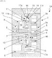
- Fig. 3 illustrates an apparatus for compressing gas-phase fluid 1a, particularly a scroll compressor having a compression mechanism disposed in a housing 2, which consists of a stator 3 and an orbiter 4, in section.
- Helical walls 3b and 4b which are respectively disposed on base plates 3a and 3a and engage with each other, define working chambers 5.
- the orbiter 4 Since the orbiter 4 is moved in circular orbit by an eccentric actuator, the helical wall 4b orbits about the stationary helical wall 3b. During the relative motion of the helical walls 3b and 4b, the walls 3b and 4b come into contact with each other many times and define a number of working chambers 5 becoming smaller. The working chambers 5 become smaller and compress a fluid by the relative motion of two intertwined helical walls 3b and 4b. A gas-phase fluid to be compressed, particularly a refrigerant is sucked to be compressed in the apparatus 1a and discharged through an outlet which is not illustrated.
- a drive shaft 6 driving the orbiter 4 is supported and maintained on the housing 2 by a first bearing 9, particularly a ball bearing.
- the drive shaft 6 and the first bearing 9 rotate about an axis of rotation 7 of the drive shaft 6.
- the first bearing 9 is disposed around the drive shaft 6 and the areas of the outer surface and side thereof abut on a wall 12 of the housing 2.
- the drive shaft 6 is mechanically connected to the orbiter 4 with eccentricity by an intermediate element 8 and a second bearing 10.
- the wall 12 limits a counter-pressure area 13 defined between the orbiter 4 and the housing 2 and forms a separation wall between the counter-pressure area 13 and a suction area 14.
- the counter-pressure area 13 is defined on the rear of the base plate 4a of the motional spiral 4 with respect to the helical wall 4b and provided to apply the pressure of the motional spiral 4 to the fixed spiral 3.
- An intermediate pressure between suction pressure and discharge pressure of a gas-phase fluid is substantially applied to the counter-pressure area 13 referred to as a counter-pressure chamber.
- a ring-shaped sealing element 15 is disposed between the facing wall 12 and the surface 16 of the motional spiral 4 aligned toward the facing wall 12.
- the sealing concept with the sealing element 15 includes a sliding element 17a formed as a plate, and the sliding element is disposed between the facing wall 12 and the spiral 4.
- the plate-type fixed sliding element 17a provides a contact surface to the surface of the motional spiral 4 together with the sealing element 15 and is provided for compensation of friction occurring during the relative motion between the facing wall 12 and the spiral 4.
- the suction area 14 and the counter-pressure area 13 are sealed from each other by the sliding element 17a and the sealing element 15.
- the sliding element 17a abuts on the facing wall 12 of the housing 2 in a sealed manner, and the sealed coupling is ensured by adhesion and lubricants, particularly refrigerant oil mixtures.
- adhesion and lubricants particularly refrigerant oil mixtures.
- a lubricant is provided for a fluid.
- the apparatus 1a includes a guide device 11 to prevent the rotation of the motional spiral 4 and achieve the orbiting thereof.
- the guide device 11 includes a number of circular openings 11a and pins 11b formed in a direction of the counter-pressure area 13 in the base plate 4a of the orbiter 4. The first ends of the pins 11b protrude into the openings 11a and the second ends thereof are coupled to the housing 2.
- the pins 11b formed as position elements and guide elements and the openings 11a formed as recesses in the base plate 4a of the motional spiral 4 are provided to guide the motional spiral 4.
- the sliding element 17a made of a corrosion-resistant and heat-resistant material having very good tribological characteristics such as steel is coupled to the housing 2, particularly the facing wall 12 without being fixed and moved thereto.
- the pins 11b made of steel as well are arranged in the openings, particularly through-bores formed in the sliding element 17a, respectively.
- the pins 11b are pressed into the openings by the sliding element 17a. Since each of the pins 11b and the sliding element 17a which are made of steel have a very high strength and a similar thermal expansion efficiency, different thermal expansions between the pins 11b and the sliding element 17a are prevented. This prevents the wall 12 of the housing 2 and thus the pins 11b to the openings 11a of the motional spiral 4 from tilting during the operation of the apparatus 1a.
- the pins 11b are continuously disposed in position and in parallel to each other, thereby ensuring an optimal guide condition for the motional spiral 4.
- the sliding element 17a is coupled to the housing 2 by external force-fit.
- the sliding element 17a formed as a plate-type or circular ring disk is pressed into the housing 2 in the area of an outer jacket, which ensures the optimal guide of the sliding element 17a in the housing.
- the housing 2 includes a recess having a side and a base surface in the area of the facing wall 12. In an assembled state, one circular ring surface of the sliding element 17a abuts on the base surface of the recess of the housing 2, and the side of the recess is coupled to the outer jacket surface of the sliding element 17a by force-fit.
- the sliding element 17a is supported in the housing 2 by at least one pin element which is not illustrated, and the pin element prevents the sliding element 17a from rotating relative to the housing 2.
- the pin element prevents the sliding element 17a from rotating relative to the housing 2.
- one or two pin elements referred to as rotation prevention pins are used.
- the pins 11b of the guide device 11 are arranged to achieve the function of the rotation prevention pins.
- the pins 11b are arranged to protrude into the facing wall 12 through the sliding element 17a abutting on the facing wall 12.
- the openings provided to accommodate the pins 11b in the sliding element 17a are formed as through-openings.
- openings or recesses are formed in the facing wall 12. In the case where the pins 11b are disposed to pass through the openings formed in the wall 12 through the sliding element 17a, the sliding element 17a is fixed on the housing 2.
- the sliding element 17a By forming the sliding element 17a as a circular ring disk made of steel with a large inner diameter, the inner diameter of the circular ring disk becomes large by the high strength of material.
- the inner diameter of the substantially hollow cylindrical-type area of the housing 2 which is limited by the facing wall 12 and provided to accommodate the bearings 9 and 10 of the intermediate element 8, also becomes large. Therefore, the counter-pressure area 13 has a large inner diameter.
- the large inner diameter of the housing 2 and the large inner diameter of the sliding element 17a in the area of the counter-pressure chamber 13 create a large installation space for the bearings 9 and 10, particularly the second bearing 10 to support the orbiter on the intermediate element 8.
- the wall thickness between the pin bore in the sliding element 17a and in some cases the facing wall 12 and the bore for the bearing 10 is minimized by the very high strength of steel which is a material of the sliding element 17a and the pins 11b.
- the installation space for the bearing 10 is increased.
- the expansion of the installation space in the counter-pressure area 13 allows the volume of the intermediate element 8 to be large and thus ensures the use of a heavier counterweight.
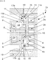
- Fig. 4 illustrates an apparatus for compressing gas-phase fluid 1b, particularly a scroll compressor having a plate-type sliding element 17b to accommodate the pins 11b of the guide device 11.
- the sliding element 17b includes a groove 18, particularly a ring-shaped groove 18 for accommodation of an O-ring.
- the groove 18 and the O-ring as a sealing element disposed in the groove extend on the outer jacket surface of the circular ring disk and seal the sliding element 17b to the facing wall 12 and thus the housing 2.
- the sliding element 17b is coupled to the housing 2 by external force-fit.
- the sliding element 17b formed as a circular ring disk is pressed into and put in the housing 2 in the area of the outer jacket.
- the sliding element 17b may be disposed to be supported in the housing 2 by at least one pin element 19 that prevents the rotation of the sliding element 17b relative to the housing 2.
- one or two pin elements 19 referred to as rotation prevention pins are used.
- the pin elements 19 are disposed within the openings formed in the sliding element 17b and protrude into the openings formed in the housing wall 12.
- the apparatus 1b including the ring-shaped groove 18 and the sliding element 17b having the O-ring, several and repetitive assembly and disassembly are possible, unlike the apparatus 1a, illustrated in Fig. 3 , including the sliding element 17a disposed by force-fit coupling.
- the sealing of the counter-pressure area to the suction area 14 is always recoverable.
- the apparatus 1b may be provided with an intermediate element 8 that has a larger volume and thus has a heavier counterweight. It is possible to more flexibly use the provided installation space because the intermediate element 8, particularly the counterweight may have an undercut shape.
- Figs. 5 and 6 are individual views illustrating the sliding element 17b of the apparatus 1b illustrated in Fig. 4 .
- the circular ring disk type sliding element 17b has an inner diameter d, an outer diameter D, and a thickness b.
- the thickness b ranges from 4 mm to 8 mm, particularly is made of about 6 mm.
- the inner diameter ranges from 50 mm to 55 mm, particularly is made of about 53 mm.
- the outer diameter ranges from 90 mm to 100 mm, particularly is made of about 96 mm.
- the pins 11b are guided or inserted into the sliding element 17b within the openings formed in the area of the inner diameter d, and the openings are uniformly distributed and arranged at the same distance.
- the pin elements 19 are rotation prevention pins, which are inserted into the sliding element 17b within the openings formed in the area of the outer diameter D.
- the present disclosure relates to an apparatus for compressing a gas-phase fluid, particularly a refrigerant.
- the apparatus includes a housing having a wall, a non-motional stator having a base plate and a helical wall extending from a first side of the base plate, and a motional orbiter having a base plate and a helical wall extending from the base plate.
- the base plates are disposed such that the wall of the stator and the wall of the orbiter engage with each other to define closed working chambers. The volumes and positions of the working chambers are changed in response to the motion of the orbiter.
Landscapes
- Engineering & Computer Science (AREA)
- Mechanical Engineering (AREA)
- General Engineering & Computer Science (AREA)
- Physics & Mathematics (AREA)
- Thermal Sciences (AREA)
- Rotary Pumps (AREA)
- Applications Or Details Of Rotary Compressors (AREA)
Claims (10)
- Einrichtung zum Verdichten eines Gasphasenfluids (1a, 1b), umfassend:- ein Gehäuse (2), das eine Wand (12) aufweist;- einen nichtbeweglichen Stator (3), der eine Bodenplatte (3a) und eine spiralförmige Wand (3b), die sich von einer Seite der Bodenplatte (3a) erstreckt, aufweist;- einen beweglichen Orbiter (4), der eine Bodenplatte (4a) und eine spiralförmige Wand (4b), die sich von der Bodenplatte (4a) erstreckt, aufweist, wobei diese Bodenplatten (3a, 4a) derart angeordnet sind, sodass die Wand (3b) des Stators (3) und die Wand (4b) des Orbiters (4) ineinandergreifen, um geschlossene Arbeitskammern (5) zu definieren, wobei Volumen und Positionen der Arbeitskammern (5) als Reaktion auf eine Bewegung des Orbiters (4) verändert werden;- eine Führungsvorrichtung (11), die mindestens eine Öffnung (11a) aufweist, die in der Bodenplatte (4a) des Orbiters (4) gebildet ist, und mindestens einen Stift (11b), der fest mit dem Gehäuse verkoppelt ist und von diesem hervorsteht, aufweist, wobei der Stift (11b) in die Öffnung (11a) eingreift; und- ein Schiebeelement (17a, 17b), das zwischen der Wand (12) des Gehäuses (2) und dem Orbiter (4) angeordnet und fest mit der Wand (12) verkoppelt ist,wobei der mindestens eine Stift (11b) in eine Öffnung gepresst wird, die in dem Schiebeelement (17a, 17b) gebildet ist,
dadurch gekennzeichnet, dassdas Schiebeelement (17a, 17b) kraftschlüssig in das Gehäuse (2) gepresst und mit diesem verkoppelt ist, unddas Gehäuse (2) eine Aussparung umfasst, die eine Seite und eine Grundfläche aufweist, wobei eine kreisförmige Ringfläche des Schiebeelements (17a, 17b) an die Grundfläche der Aussparung angrenzt und die Seite der Aussparung in die äußere Mantelfläche des Schiebeelements (17a, 17b) eingepasst und mit diesem verkoppelt ist. - Einrichtung nach Anspruch 1, wobei
das Schiebeelement (17a, 17b) eine kreisförmige Ringscheibenform aufweist, die einen Innendurchmesser (d), einen Außendurchmesser (D), eine Dicke (b), eine äußere Mantelfläche und zwei kreisförmige Ringflächen aufweist. - Einrichtung nach Anspruch 1, wobei
das Schiebeelement (17a, 17b) und der mindestens eine Stift (11b) aus Materialien bestehen, bei denen die Werte der Stärke und des Wärmeausdehnungskoeffizienten als Materialmerkmale in demselben Bereich liegen - Einrichtung nach Anspruch 1,
wobei das Schiebeelement (17a, 17b) aus Stahl besteht. - Einrichtung nach Anspruch 1,
wobei der mindestens eine Stift (11b) aus Stahl besteht. - Einrichtung nach Anspruch 1, wobei
das Schiebeelement (17b) eine ringförmige Nut (18) zur Aufnahme eines Schiebeelements, das als ein O-Ring gebildet ist, umfasst. - Einrichtung nach Anspruch 6, wobei
die ringförmige Nut (18) an einer äußeren Mantelfläche des Schiebeelements (17b) gebildet ist. - Einrichtung nach Anspruch 1, wobei
mindestens eine Öffnung in dem Schiebeelement (17a, 17b) zur Aufnahme des Stifts (11b) als eine Durchgangsbohrung gebildet ist. - Einrichtung nach Anspruch 8, wobei
der mindestens eine Stift (11b) der Führungsvorrichtung (11) derart in der Durchgangsbohrung angeordnet ist, sodass ein Ende des Stifts (11b), das entfernt von einem Ende der Führungsvorrichtung (11) gebildet ist, der in die Öffnung (11a) eingreift, in eine Öffnung eingreift, die in der Wand (12) des Gehäuses (2) durch das Schiebeelement (17a) hindurch gebildet ist. - Einrichtung nach Anspruch 1, wobei
die Einrichtung Stiftelemente (19) umfasst, die gebildet sind, um innerhalb der in dem Schiebeelement (17b) gebildeten Öffnungen angeordnet zu sein und um in die in der Wand (12) des Gehäuses (2) gebildeten Öffnungen hineinzuragen.
Applications Claiming Priority (2)
| Application Number | Priority Date | Filing Date | Title |
|---|---|---|---|
| DE102016118525.6A DE102016118525B4 (de) | 2016-09-29 | 2016-09-29 | Vorrichtung zur Verdichtung eines gasförmigen Fluids |
| PCT/KR2017/008956 WO2018062684A1 (ko) | 2016-09-29 | 2017-08-17 | 기상 유체의 압축 장치 |
Publications (3)
| Publication Number | Publication Date |
|---|---|
| EP3521625A1 EP3521625A1 (de) | 2019-08-07 |
| EP3521625A4 EP3521625A4 (de) | 2020-05-20 |
| EP3521625B1 true EP3521625B1 (de) | 2022-10-12 |
Family
ID=61564204
Family Applications (1)
| Application Number | Title | Priority Date | Filing Date |
|---|---|---|---|
| EP17856570.1A Active EP3521625B1 (de) | 2016-09-29 | 2017-08-17 | Gasförmige fluidverdichtungsvorrichtung |
Country Status (7)
| Country | Link |
|---|---|
| US (1) | US11002272B2 (de) |
| EP (1) | EP3521625B1 (de) |
| JP (1) | JP6706346B2 (de) |
| KR (1) | KR101923491B1 (de) |
| CN (1) | CN109477481B (de) |
| DE (1) | DE102016118525B4 (de) |
| WO (1) | WO2018062684A1 (de) |
Families Citing this family (8)
| Publication number | Priority date | Publication date | Assignee | Title |
|---|---|---|---|---|
| KR20200080820A (ko) | 2018-12-27 | 2020-07-07 | 한온시스템 주식회사 | 스크롤 압축기 |
| DE102020122570A1 (de) | 2020-08-28 | 2022-03-03 | Hanon Systems | Spiralverdichter für ein gasförmiges Fluid und Verfahren zum Betreiben desselben |
| DE102020134469A1 (de) * | 2020-12-21 | 2022-06-23 | OET GmbH | Scrollverdichter zur Erzeugung von ölfreier Druckluft |
| US11885535B2 (en) | 2021-06-11 | 2024-01-30 | Hanon Systems | ETXV direct discharge injection compressor |
| DE102021207102A1 (de) | 2021-07-06 | 2023-01-12 | Brose Fahrzeugteile SE & Co. Kommanditgesellschaft, Würzburg | Scrollmaschine |
| DE102022111377A1 (de) | 2022-05-06 | 2023-11-09 | OET GmbH | Verdrängermaschine nach dem Spiralprinzip |
| DE102022134443A1 (de) | 2022-12-21 | 2024-06-27 | OET GmbH | Verdrängermaschine |
| DE102024201453A1 (de) * | 2024-02-16 | 2025-08-21 | Brose Fahrzeugteile SE & Co. Kommanditgesellschaft, Würzburg | Scrollmaschine |
Family Cites Families (31)
| Publication number | Priority date | Publication date | Assignee | Title |
|---|---|---|---|---|
| JPS60206989A (ja) * | 1984-03-30 | 1985-10-18 | Mitsubishi Electric Corp | スクロ−ル形流体機械 |
| JPH0668276B2 (ja) | 1986-02-27 | 1994-08-31 | 株式会社日本自動車部品総合研究所 | 公転型圧縮機 |
| JPH0788822B2 (ja) | 1989-04-20 | 1995-09-27 | 株式会社日立製作所 | オイルフリー式スクロール形流体機械 |
| JPH08338376A (ja) | 1995-06-12 | 1996-12-24 | Nippondenso Co Ltd | スクロール型圧縮機 |
| JP3218423B2 (ja) * | 1995-12-01 | 2001-10-15 | 株式会社日立製作所 | スクロール流体機械 |
| CN1072774C (zh) * | 1995-12-15 | 2001-10-10 | 甘肃工业大学 | 涡旋型流体随变式机械的防自转机构 |
| JPH09228967A (ja) * | 1996-02-20 | 1997-09-02 | Matsushita Electric Ind Co Ltd | スクロール圧縮機 |
| JPH09303275A (ja) * | 1996-05-10 | 1997-11-25 | Sanden Corp | スクロール型圧縮機 |
| JP2001132670A (ja) * | 1999-11-09 | 2001-05-18 | Sanden Corp | スクロール型圧縮機 |
| KR100446213B1 (ko) * | 2001-11-29 | 2004-08-30 | 주식회사 롤텍 | 스크롤압축기의 실링구조 |
| JP2004124735A (ja) * | 2002-09-30 | 2004-04-22 | Tokico Ltd | スクロール式流体機械 |
| JP4013730B2 (ja) | 2002-10-25 | 2007-11-28 | 株式会社豊田自動織機 | スクロールコンプレッサ |
| JP2004301092A (ja) | 2003-03-31 | 2004-10-28 | Toyota Industries Corp | スクロール圧縮機 |
| JP2006068276A (ja) * | 2004-09-02 | 2006-03-16 | Matsushita Electric Ind Co Ltd | 炊飯器 |
| JP2007291879A (ja) | 2006-04-21 | 2007-11-08 | Sanden Corp | スクロール型流体機械 |
| JP5039327B2 (ja) | 2006-06-14 | 2012-10-03 | 三菱重工業株式会社 | スクロール圧縮機 |
| JP5270960B2 (ja) | 2008-05-22 | 2013-08-21 | サンデン株式会社 | スクロール型圧縮機 |
| JP2010190074A (ja) | 2009-02-17 | 2010-09-02 | Toyota Industries Corp | スクロール型流体機械 |
| JP5609699B2 (ja) * | 2011-02-15 | 2014-10-22 | 株式会社豊田自動織機 | スクロール型圧縮機 |
| JP2012229650A (ja) * | 2011-04-26 | 2012-11-22 | Sanden Corp | スクロール型流体機械 |
| JP5637151B2 (ja) | 2012-01-20 | 2014-12-10 | 株式会社豊田自動織機 | 差圧弁及び差圧弁を備える電動圧縮機 |
| WO2014002970A1 (ja) * | 2012-06-27 | 2014-01-03 | 株式会社豊田自動織機 | スクロール型圧縮機 |
| KR101692577B1 (ko) * | 2013-01-25 | 2017-01-03 | 한온시스템 주식회사 | 스크롤 압축기 |
| JP6578504B2 (ja) * | 2013-04-30 | 2019-09-25 | パナソニックIpマネジメント株式会社 | スクロール圧縮機 |
| JP2015028304A (ja) * | 2013-07-30 | 2015-02-12 | サンデン株式会社 | スクロール型流体機械 |
| JP2015034506A (ja) * | 2013-08-08 | 2015-02-19 | 株式会社豊田自動織機 | スクロール型圧縮機 |
| JP6245937B2 (ja) | 2013-10-25 | 2017-12-13 | 株式会社ヴァレオジャパン | 電動スクロール圧縮機 |
| JP6207970B2 (ja) * | 2013-10-30 | 2017-10-04 | サンデンホールディングス株式会社 | スクロール型流体機械 |
| JP6442171B2 (ja) | 2014-06-27 | 2018-12-19 | 三菱重工サーマルシステムズ株式会社 | スクロール圧縮機 |
| JP2016156297A (ja) * | 2015-02-24 | 2016-09-01 | ジョンソンコントロールズ ヒタチ エア コンディショニング テクノロジー(ホンコン)リミテッド | スクロール圧縮機 |
| US20160369799A1 (en) * | 2015-06-18 | 2016-12-22 | Bitzer Kuehlmaschinenbau Gmbh | Separator plate with inlet curve |
-
2016
- 2016-09-29 DE DE102016118525.6A patent/DE102016118525B4/de active Active
-
2017
- 2017-05-31 KR KR1020170067497A patent/KR101923491B1/ko active Active
- 2017-08-17 WO PCT/KR2017/008956 patent/WO2018062684A1/ko not_active Ceased
- 2017-08-17 US US16/301,619 patent/US11002272B2/en active Active
- 2017-08-17 EP EP17856570.1A patent/EP3521625B1/de active Active
- 2017-08-17 CN CN201780043212.XA patent/CN109477481B/zh active Active
- 2017-08-17 JP JP2018558242A patent/JP6706346B2/ja active Active
Also Published As
| Publication number | Publication date |
|---|---|
| EP3521625A1 (de) | 2019-08-07 |
| KR20180035650A (ko) | 2018-04-06 |
| WO2018062684A1 (ko) | 2018-04-05 |
| JP2019515184A (ja) | 2019-06-06 |
| EP3521625A4 (de) | 2020-05-20 |
| US11002272B2 (en) | 2021-05-11 |
| US20190285066A1 (en) | 2019-09-19 |
| DE102016118525A1 (de) | 2018-03-29 |
| DE102016118525B4 (de) | 2019-09-19 |
| CN109477481B (zh) | 2020-06-30 |
| JP6706346B2 (ja) | 2020-06-03 |
| KR101923491B1 (ko) | 2018-11-30 |
| CN109477481A (zh) | 2019-03-15 |
Similar Documents
| Publication | Publication Date | Title |
|---|---|---|
| EP3521625B1 (de) | Gasförmige fluidverdichtungsvorrichtung | |
| US10801495B2 (en) | Oil flow through the bearings of a scroll compressor | |
| EP0070888B1 (de) | Apparat mit Verdrängerwirkung vom Spiral-Drehkolbentyp, und Methode zur Herstellung von Dichtungsmittel für einen solchen Apparat | |
| US9080446B2 (en) | Scroll compressor with captured thrust washer | |
| KR100916554B1 (ko) | 올덤 커플링을 위한 클리어런스를 가진 스크롤 압축기 | |
| US20070178002A1 (en) | Scroll compressor | |
| CN110469504B (zh) | 具有衬套的压缩机 | |
| WO2007111903A1 (en) | Scroll machine using floating seal with backer | |
| US7997883B2 (en) | Scroll compressor with scroll deflection compensation | |
| CN112654787A (zh) | 共同旋转的涡旋压缩机的径向顺应性 | |
| JP2003206873A (ja) | スクロール圧縮機 | |
| EP1701040A2 (de) | Doppel- Spiralverdichter mit einem anti-schub Ring | |
| KR20020090108A (ko) | 압축기 | |
| KR20030042416A (ko) | 사판형 압축기 | |
| US6033194A (en) | Scroll-type fluid displacement apparatus with anti-wear plate mechanism | |
| EP1195520A2 (de) | Taumelscheibenverdichtergehäuse | |
| JPH09195958A (ja) | スクロール型圧縮機 | |
| KR101986287B1 (ko) | 가스 상태의 유체를 압축하기 위한 장치 | |
| US6419470B2 (en) | Scroll compressor | |
| KR20260034255A (ko) | 스크롤 압축기 | |
| CN119998574A (zh) | 密封圈 | |
| CN117803572A (zh) | 涡旋压缩机 | |
| KR20220091135A (ko) | 스크롤 압축기 | |
| WO2020008798A1 (ja) | 流体機械 | |
| CN111441941A (zh) | 定涡旋部件、压缩组件和涡旋压缩机 |
Legal Events
| Date | Code | Title | Description |
|---|---|---|---|
| STAA | Information on the status of an ep patent application or granted ep patent |
Free format text: STATUS: THE INTERNATIONAL PUBLICATION HAS BEEN MADE |
|
| PUAI | Public reference made under article 153(3) epc to a published international application that has entered the european phase |
Free format text: ORIGINAL CODE: 0009012 |
|
| STAA | Information on the status of an ep patent application or granted ep patent |
Free format text: STATUS: REQUEST FOR EXAMINATION WAS MADE |
|
| 17P | Request for examination filed |
Effective date: 20181205 |
|
| AK | Designated contracting states |
Kind code of ref document: A1 Designated state(s): AL AT BE BG CH CY CZ DE DK EE ES FI FR GB GR HR HU IE IS IT LI LT LU LV MC MK MT NL NO PL PT RO RS SE SI SK SM TR |
|
| AX | Request for extension of the european patent |
Extension state: BA ME |
|
| DAV | Request for validation of the european patent (deleted) | ||
| DAX | Request for extension of the european patent (deleted) | ||
| A4 | Supplementary search report drawn up and despatched |
Effective date: 20200422 |
|
| RIC1 | Information provided on ipc code assigned before grant |
Ipc: F04C 18/02 20060101AFI20200416BHEP Ipc: F04C 28/22 20060101ALI20200416BHEP |
|
| STAA | Information on the status of an ep patent application or granted ep patent |
Free format text: STATUS: EXAMINATION IS IN PROGRESS |
|
| 17Q | First examination report despatched |
Effective date: 20210716 |
|
| GRAP | Despatch of communication of intention to grant a patent |
Free format text: ORIGINAL CODE: EPIDOSNIGR1 |
|
| STAA | Information on the status of an ep patent application or granted ep patent |
Free format text: STATUS: GRANT OF PATENT IS INTENDED |
|
| INTG | Intention to grant announced |
Effective date: 20220506 |
|
| GRAS | Grant fee paid |
Free format text: ORIGINAL CODE: EPIDOSNIGR3 |
|
| GRAA | (expected) grant |
Free format text: ORIGINAL CODE: 0009210 |
|
| STAA | Information on the status of an ep patent application or granted ep patent |
Free format text: STATUS: THE PATENT HAS BEEN GRANTED |
|
| AK | Designated contracting states |
Kind code of ref document: B1 Designated state(s): AL AT BE BG CH CY CZ DK EE ES FI FR GB GR HR HU IE IS IT LI LT LU LV MC MK MT NL NO PL PT RO RS SE SI SK SM TR |
|
| RBV | Designated contracting states (corrected) |
Designated state(s): AL AT BE BG CH CY CZ DK EE ES FI FR GB GR HR HU IE IS IT LI LT LU LV MC MK MT NL NO PL PT RO RS SE SI SK SM TR |
|
| REG | Reference to a national code |
Ref country code: DE Ref legal event code: R108 Ref country code: GB Ref legal event code: FG4D |
|
| REG | Reference to a national code |
Ref country code: CH Ref legal event code: EP |
|
| REG | Reference to a national code |
Ref country code: IE Ref legal event code: FG4D |
|
| REG | Reference to a national code |
Ref country code: SE Ref legal event code: TRGR Ref country code: AT Ref legal event code: REF Ref document number: 1524327 Country of ref document: AT Kind code of ref document: T Effective date: 20221115 |
|
| REG | Reference to a national code |
Ref country code: LT Ref legal event code: MG9D |
|
| REG | Reference to a national code |
Ref country code: NL Ref legal event code: MP Effective date: 20221012 |
|
| REG | Reference to a national code |
Ref country code: AT Ref legal event code: MK05 Ref document number: 1524327 Country of ref document: AT Kind code of ref document: T Effective date: 20221012 |
|
| PG25 | Lapsed in a contracting state [announced via postgrant information from national office to epo] |
Ref country code: NL Free format text: LAPSE BECAUSE OF FAILURE TO SUBMIT A TRANSLATION OF THE DESCRIPTION OR TO PAY THE FEE WITHIN THE PRESCRIBED TIME-LIMIT Effective date: 20221012 |
|
| PG25 | Lapsed in a contracting state [announced via postgrant information from national office to epo] |
Ref country code: PT Free format text: LAPSE BECAUSE OF FAILURE TO SUBMIT A TRANSLATION OF THE DESCRIPTION OR TO PAY THE FEE WITHIN THE PRESCRIBED TIME-LIMIT Effective date: 20230213 Ref country code: NO Free format text: LAPSE BECAUSE OF FAILURE TO SUBMIT A TRANSLATION OF THE DESCRIPTION OR TO PAY THE FEE WITHIN THE PRESCRIBED TIME-LIMIT Effective date: 20230112 Ref country code: LT Free format text: LAPSE BECAUSE OF FAILURE TO SUBMIT A TRANSLATION OF THE DESCRIPTION OR TO PAY THE FEE WITHIN THE PRESCRIBED TIME-LIMIT Effective date: 20221012 Ref country code: FI Free format text: LAPSE BECAUSE OF FAILURE TO SUBMIT A TRANSLATION OF THE DESCRIPTION OR TO PAY THE FEE WITHIN THE PRESCRIBED TIME-LIMIT Effective date: 20221012 Ref country code: ES Free format text: LAPSE BECAUSE OF FAILURE TO SUBMIT A TRANSLATION OF THE DESCRIPTION OR TO PAY THE FEE WITHIN THE PRESCRIBED TIME-LIMIT Effective date: 20221012 Ref country code: AT Free format text: LAPSE BECAUSE OF FAILURE TO SUBMIT A TRANSLATION OF THE DESCRIPTION OR TO PAY THE FEE WITHIN THE PRESCRIBED TIME-LIMIT Effective date: 20221012 |
|
| PG25 | Lapsed in a contracting state [announced via postgrant information from national office to epo] |
Ref country code: RS Free format text: LAPSE BECAUSE OF FAILURE TO SUBMIT A TRANSLATION OF THE DESCRIPTION OR TO PAY THE FEE WITHIN THE PRESCRIBED TIME-LIMIT Effective date: 20221012 Ref country code: PL Free format text: LAPSE BECAUSE OF FAILURE TO SUBMIT A TRANSLATION OF THE DESCRIPTION OR TO PAY THE FEE WITHIN THE PRESCRIBED TIME-LIMIT Effective date: 20221012 Ref country code: LV Free format text: LAPSE BECAUSE OF FAILURE TO SUBMIT A TRANSLATION OF THE DESCRIPTION OR TO PAY THE FEE WITHIN THE PRESCRIBED TIME-LIMIT Effective date: 20221012 Ref country code: IS Free format text: LAPSE BECAUSE OF FAILURE TO SUBMIT A TRANSLATION OF THE DESCRIPTION OR TO PAY THE FEE WITHIN THE PRESCRIBED TIME-LIMIT Effective date: 20230212 Ref country code: HR Free format text: LAPSE BECAUSE OF FAILURE TO SUBMIT A TRANSLATION OF THE DESCRIPTION OR TO PAY THE FEE WITHIN THE PRESCRIBED TIME-LIMIT Effective date: 20221012 Ref country code: GR Free format text: LAPSE BECAUSE OF FAILURE TO SUBMIT A TRANSLATION OF THE DESCRIPTION OR TO PAY THE FEE WITHIN THE PRESCRIBED TIME-LIMIT Effective date: 20230113 |
|
| P01 | Opt-out of the competence of the unified patent court (upc) registered |
Effective date: 20230615 |
|
| PG25 | Lapsed in a contracting state [announced via postgrant information from national office to epo] |
Ref country code: SM Free format text: LAPSE BECAUSE OF FAILURE TO SUBMIT A TRANSLATION OF THE DESCRIPTION OR TO PAY THE FEE WITHIN THE PRESCRIBED TIME-LIMIT Effective date: 20221012 Ref country code: RO Free format text: LAPSE BECAUSE OF FAILURE TO SUBMIT A TRANSLATION OF THE DESCRIPTION OR TO PAY THE FEE WITHIN THE PRESCRIBED TIME-LIMIT Effective date: 20221012 Ref country code: EE Free format text: LAPSE BECAUSE OF FAILURE TO SUBMIT A TRANSLATION OF THE DESCRIPTION OR TO PAY THE FEE WITHIN THE PRESCRIBED TIME-LIMIT Effective date: 20221012 Ref country code: DK Free format text: LAPSE BECAUSE OF FAILURE TO SUBMIT A TRANSLATION OF THE DESCRIPTION OR TO PAY THE FEE WITHIN THE PRESCRIBED TIME-LIMIT Effective date: 20221012 Ref country code: CZ Free format text: LAPSE BECAUSE OF FAILURE TO SUBMIT A TRANSLATION OF THE DESCRIPTION OR TO PAY THE FEE WITHIN THE PRESCRIBED TIME-LIMIT Effective date: 20221012 |
|
| PLBE | No opposition filed within time limit |
Free format text: ORIGINAL CODE: 0009261 |
|
| STAA | Information on the status of an ep patent application or granted ep patent |
Free format text: STATUS: NO OPPOSITION FILED WITHIN TIME LIMIT |
|
| PG25 | Lapsed in a contracting state [announced via postgrant information from national office to epo] |
Ref country code: SK Free format text: LAPSE BECAUSE OF FAILURE TO SUBMIT A TRANSLATION OF THE DESCRIPTION OR TO PAY THE FEE WITHIN THE PRESCRIBED TIME-LIMIT Effective date: 20221012 Ref country code: AL Free format text: LAPSE BECAUSE OF FAILURE TO SUBMIT A TRANSLATION OF THE DESCRIPTION OR TO PAY THE FEE WITHIN THE PRESCRIBED TIME-LIMIT Effective date: 20221012 |
|
| 26N | No opposition filed |
Effective date: 20230713 |
|
| PG25 | Lapsed in a contracting state [announced via postgrant information from national office to epo] |
Ref country code: SI Free format text: LAPSE BECAUSE OF FAILURE TO SUBMIT A TRANSLATION OF THE DESCRIPTION OR TO PAY THE FEE WITHIN THE PRESCRIBED TIME-LIMIT Effective date: 20221012 |
|
| PG25 | Lapsed in a contracting state [announced via postgrant information from national office to epo] |
Ref country code: MC Free format text: LAPSE BECAUSE OF FAILURE TO SUBMIT A TRANSLATION OF THE DESCRIPTION OR TO PAY THE FEE WITHIN THE PRESCRIBED TIME-LIMIT Effective date: 20221012 |
|
| REG | Reference to a national code |
Ref country code: CH Ref legal event code: PL |
|
| PG25 | Lapsed in a contracting state [announced via postgrant information from national office to epo] |
Ref country code: MC Free format text: LAPSE BECAUSE OF FAILURE TO SUBMIT A TRANSLATION OF THE DESCRIPTION OR TO PAY THE FEE WITHIN THE PRESCRIBED TIME-LIMIT Effective date: 20221012 |
|
| PG25 | Lapsed in a contracting state [announced via postgrant information from national office to epo] |
Ref country code: LU Free format text: LAPSE BECAUSE OF NON-PAYMENT OF DUE FEES Effective date: 20230817 |
|
| PG25 | Lapsed in a contracting state [announced via postgrant information from national office to epo] |
Ref country code: LU Free format text: LAPSE BECAUSE OF NON-PAYMENT OF DUE FEES Effective date: 20230817 Ref country code: CH Free format text: LAPSE BECAUSE OF NON-PAYMENT OF DUE FEES Effective date: 20230831 |
|
| REG | Reference to a national code |
Ref country code: BE Ref legal event code: MM Effective date: 20230831 |
|
| REG | Reference to a national code |
Ref country code: IE Ref legal event code: MM4A |
|
| PG25 | Lapsed in a contracting state [announced via postgrant information from national office to epo] |
Ref country code: IE Free format text: LAPSE BECAUSE OF NON-PAYMENT OF DUE FEES Effective date: 20230817 |
|
| PG25 | Lapsed in a contracting state [announced via postgrant information from national office to epo] |
Ref country code: IE Free format text: LAPSE BECAUSE OF NON-PAYMENT OF DUE FEES Effective date: 20230817 |
|
| PG25 | Lapsed in a contracting state [announced via postgrant information from national office to epo] |
Ref country code: BE Free format text: LAPSE BECAUSE OF NON-PAYMENT OF DUE FEES Effective date: 20230831 |
|
| PG25 | Lapsed in a contracting state [announced via postgrant information from national office to epo] |
Ref country code: BG Free format text: LAPSE BECAUSE OF FAILURE TO SUBMIT A TRANSLATION OF THE DESCRIPTION OR TO PAY THE FEE WITHIN THE PRESCRIBED TIME-LIMIT Effective date: 20221012 |
|
| PG25 | Lapsed in a contracting state [announced via postgrant information from national office to epo] |
Ref country code: BG Free format text: LAPSE BECAUSE OF FAILURE TO SUBMIT A TRANSLATION OF THE DESCRIPTION OR TO PAY THE FEE WITHIN THE PRESCRIBED TIME-LIMIT Effective date: 20221012 |
|
| PG25 | Lapsed in a contracting state [announced via postgrant information from national office to epo] |
Ref country code: CY Free format text: LAPSE BECAUSE OF FAILURE TO SUBMIT A TRANSLATION OF THE DESCRIPTION OR TO PAY THE FEE WITHIN THE PRESCRIBED TIME-LIMIT; INVALID AB INITIO Effective date: 20170817 |
|
| PG25 | Lapsed in a contracting state [announced via postgrant information from national office to epo] |
Ref country code: HU Free format text: LAPSE BECAUSE OF FAILURE TO SUBMIT A TRANSLATION OF THE DESCRIPTION OR TO PAY THE FEE WITHIN THE PRESCRIBED TIME-LIMIT; INVALID AB INITIO Effective date: 20170817 |
|
| PGFP | Annual fee paid to national office [announced via postgrant information from national office to epo] |
Ref country code: IT Payment date: 20250722 Year of fee payment: 9 |
|
| PGFP | Annual fee paid to national office [announced via postgrant information from national office to epo] |
Ref country code: GB Payment date: 20250703 Year of fee payment: 9 |
|
| PGFP | Annual fee paid to national office [announced via postgrant information from national office to epo] |
Ref country code: FR Payment date: 20250708 Year of fee payment: 9 |
|
| PGFP | Annual fee paid to national office [announced via postgrant information from national office to epo] |
Ref country code: SE Payment date: 20250710 Year of fee payment: 9 |
|
| PG25 | Lapsed in a contracting state [announced via postgrant information from national office to epo] |
Ref country code: TR Free format text: LAPSE BECAUSE OF FAILURE TO SUBMIT A TRANSLATION OF THE DESCRIPTION OR TO PAY THE FEE WITHIN THE PRESCRIBED TIME-LIMIT Effective date: 20221012 |