EP3486397B1 - Marquise - Google Patents
Marquise Download PDFInfo
- Publication number
- EP3486397B1 EP3486397B1 EP18020594.0A EP18020594A EP3486397B1 EP 3486397 B1 EP3486397 B1 EP 3486397B1 EP 18020594 A EP18020594 A EP 18020594A EP 3486397 B1 EP3486397 B1 EP 3486397B1
- Authority
- EP
- European Patent Office
- Prior art keywords
- awning
- housing
- swivel
- accordance
- groove
- Prior art date
- Legal status (The legal status is an assumption and is not a legal conclusion. Google has not performed a legal analysis and makes no representation as to the accuracy of the status listed.)
- Active
Links
Images


Classifications
-
- E—FIXED CONSTRUCTIONS
- E04—BUILDING
- E04F—FINISHING WORK ON BUILDINGS, e.g. STAIRS, FLOORS
- E04F10/00—Sunshades, e.g. Florentine blinds or jalousies; Outside screens; Awnings or baldachins
- E04F10/02—Sunshades, e.g. Florentine blinds or jalousies; Outside screens; Awnings or baldachins of flexible canopy materials, e.g. canvas ; Baldachins
- E04F10/06—Sunshades, e.g. Florentine blinds or jalousies; Outside screens; Awnings or baldachins of flexible canopy materials, e.g. canvas ; Baldachins comprising a roller-blind with means for holding the end away from a building
- E04F10/0607—Sunshades, e.g. Florentine blinds or jalousies; Outside screens; Awnings or baldachins of flexible canopy materials, e.g. canvas ; Baldachins comprising a roller-blind with means for holding the end away from a building with guiding-sections for supporting the movable end of the blind
-
- E—FIXED CONSTRUCTIONS
- E04—BUILDING
- E04F—FINISHING WORK ON BUILDINGS, e.g. STAIRS, FLOORS
- E04F10/00—Sunshades, e.g. Florentine blinds or jalousies; Outside screens; Awnings or baldachins
- E04F10/02—Sunshades, e.g. Florentine blinds or jalousies; Outside screens; Awnings or baldachins of flexible canopy materials, e.g. canvas ; Baldachins
- E04F10/06—Sunshades, e.g. Florentine blinds or jalousies; Outside screens; Awnings or baldachins of flexible canopy materials, e.g. canvas ; Baldachins comprising a roller-blind with means for holding the end away from a building
- E04F10/0637—Sunshades, e.g. Florentine blinds or jalousies; Outside screens; Awnings or baldachins of flexible canopy materials, e.g. canvas ; Baldachins comprising a roller-blind with means for holding the end away from a building with mechanisms for adjusting the inclination of the blind
-
- E—FIXED CONSTRUCTIONS
- E04—BUILDING
- E04F—FINISHING WORK ON BUILDINGS, e.g. STAIRS, FLOORS
- E04F10/00—Sunshades, e.g. Florentine blinds or jalousies; Outside screens; Awnings or baldachins
- E04F10/02—Sunshades, e.g. Florentine blinds or jalousies; Outside screens; Awnings or baldachins of flexible canopy materials, e.g. canvas ; Baldachins
- E04F10/06—Sunshades, e.g. Florentine blinds or jalousies; Outside screens; Awnings or baldachins of flexible canopy materials, e.g. canvas ; Baldachins comprising a roller-blind with means for holding the end away from a building
- E04F10/0662—Sunshades, e.g. Florentine blinds or jalousies; Outside screens; Awnings or baldachins of flexible canopy materials, e.g. canvas ; Baldachins comprising a roller-blind with means for holding the end away from a building with arrangements for fastening the blind to the building
-
- E—FIXED CONSTRUCTIONS
- E04—BUILDING
- E04F—FINISHING WORK ON BUILDINGS, e.g. STAIRS, FLOORS
- E04F10/00—Sunshades, e.g. Florentine blinds or jalousies; Outside screens; Awnings or baldachins
- E04F10/02—Sunshades, e.g. Florentine blinds or jalousies; Outside screens; Awnings or baldachins of flexible canopy materials, e.g. canvas ; Baldachins
- E04F10/06—Sunshades, e.g. Florentine blinds or jalousies; Outside screens; Awnings or baldachins of flexible canopy materials, e.g. canvas ; Baldachins comprising a roller-blind with means for holding the end away from a building
- E04F10/0666—Accessories
- E04F10/0681—Support posts for the movable end of the blind
-
- E—FIXED CONSTRUCTIONS
- E04—BUILDING
- E04F—FINISHING WORK ON BUILDINGS, e.g. STAIRS, FLOORS
- E04F10/00—Sunshades, e.g. Florentine blinds or jalousies; Outside screens; Awnings or baldachins
- E04F10/02—Sunshades, e.g. Florentine blinds or jalousies; Outside screens; Awnings or baldachins of flexible canopy materials, e.g. canvas ; Baldachins
- E04F10/06—Sunshades, e.g. Florentine blinds or jalousies; Outside screens; Awnings or baldachins of flexible canopy materials, e.g. canvas ; Baldachins comprising a roller-blind with means for holding the end away from a building
- E04F10/0685—Covers or housings for the rolled-up blind
Definitions
- the invention relates to an awning with an awning fabric accommodated on a winding shaft arranged in a housing, the front end of which is attached to a tension profile which, with its lateral end regions, is guided in guide rails extending in the direction of the awning fabric and protruding from the housing attached thereto, which are added to the formation of a patio roof awning via releasably attachable supports on a patio roof.
- a patio roof awning of this type is for example from the DE 101 50 709 C2 known.
- the known arrangements of this type only allow use as a patio roof awning in which the housing containing the winding shaft protrudes in a self-supporting manner from the upper end of the guide rails mounted on the patio roof. No other use is possible here.
- the guide rails for forming a pergola awning without the supports can only be detached in the area of their front ends the upper end of a respectively assigned support are connected and that the housing is accommodated on detachably attached wall brackets, each of which has a pivoting piece pivotably mounted about an axis parallel to the winding shaft, which is designed as a partial shell that encompasses a facing, rear region of the housing and is detachably attached to it .
- the housing containing the winding shaft can simply be brought into engagement with the swivel pieces of the already pre-assembled wall brackets, which already results in a temporary hold of the entire unit consisting of the housing and guide rails attached to it and thus facilitates its final assembly .
- the pivoting pieces can each be assigned a stop device limiting their pivoting angle with respect to the assigned wall bracket. This ensures that the awning, which is hung with its housing in the swivel pieces, is already held in such a way that it cannot fall down and the housing can be easily screwed to the swivel pieces, which simplifies the overall assembly process.
- the pivoting pieces each have a bearing vane formed by a rear thickening, assigned to a bearing block provided on the console side and connected to it by a bearing pin parallel to the winding shaft, which is provided in its lower circumferential area with a tangential projection, which to form a stop device with a console-side Counter surface cooperates.
- the front ends of the guide rails can each be connected to the upper end of an assigned post or the like via a tilting joint holding a tilting axis parallel to the winding shaft.
- the tilting joints, together with the pivoting mounting of the pivoting pieces, result in a high degree of variability with regard to the inclination of the pergola awning created in this way and thus ensure easy adaptability to structural conditions found on site.
- a further advantageous embodiment can consist in the fact that the partial shells forming the swivel pieces are each designed as two-armed swivel levers with arms extending in opposite directions from their swivel bearing, the upper end of the upper arm having a rear bend that forms a hook-in claw and the housing in its
- the upper end of the upper arm of the swivel lever associated peripheral region has an undercut, continuous hanging groove into which the swivel pieces can be hung with their hanging claws.
- the housing can have a continuous T-groove removed from the hanging groove, in which the sliding blocks assigned to the pivoting pieces can be accommodated, which are provided with a threaded hole into which a retaining screw engaged on the assigned pivoting piece can be screwed, whereby a fixed connection is established .
- the Screw connection can be provided in the area of the lower arms of the swivel pieces.
- the lower arms of the pivoting pieces can advantageously be tapered in thickness towards their end, so that the result is a slim design of the partial shells that encompass the facing housing area and form the pivoting pieces.
- the number of wall brackets used can be freely selected depending on the length of the housing. At least two wall brackets are always provided. With a larger housing length, however, several wall brackets evenly distributed over the length can be provided.
- a terrace roof construction is indicated that has horizontal purlins 1 and rafters 2 recorded transversely thereto.
- the front purlin 1 is held on vertical columns 3 in the example shown.
- the rear purlin 1 is attached to a building wall 4.
- the height of the purlins 1 is offset from one another in such a way that the rafters 2 slope from the back to the front.
- the spaces between the rafters 2 are filled in by panel-shaped glass roof elements 5 carried by them.
- a so-called patio roof awning 6 is assigned to the glass roof formed in this way to enable shading.
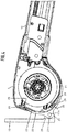
- FIG. 1 This includes one on one in the Figures 1 and 2 Not shown in detail, in the area of the rear edge of the glass roof placed housing 7 rotatably mounted winding shaft absorbable awning fabric 8, which is attached with its front end to a winding shaft parallel tension profile 9, which with its lateral ends or runners attached to it in the direction of the awning fabric 8 extending, from the attached housing 7 protruding guide rails 10 is guided.
- the guide rails 10 are accommodated by means of support feet 11 projecting from their underside and distributed over their length on a part of the terrace roof structure located below, here in the form of a rafter 2 and spaced therefrom.
- the support feet 11 are removable elements which, on the one hand, can be detachably screwed from below onto the respectively assigned guide rail 10 and, on the other hand, from above onto the respectively assigned rafters 8, etc., or detachable therefrom.
- the guide rails 10 and the housing attached thereto are connected to the terrace roof construction with a roof clearance.
- the guide rails 10 and the housing 7 are firmly connected to one another.
- the housing 7 therefore protrudes from the rear end of the guide rails 10 in a self-supporting manner without touching the elements of the terrace roof construction.
- the support feet 11, by means of which the guide rails 10 are fastened parallel to the rafters on the terrace roof structure located below, have a corresponding length.
- the housing 7 is around an in Figure 3
- the indicated pivot axis 17 parallel to the winding shaft is mounted pivotably on the associated wall brackets 15.
- the front end regions of the guide rails 10 are each connected to the support structure formed here by the supports 16 via a tilting axis 18 containing tilting axes 18 parallel to the winding shaft.
- the for the patio roof awning according to Figures 1 and 2 Required support feet 11 are not required here and can therefore be removed.
- the wall brackets 15 and tilting joints 16 are used here as supporting elements.
- the plate-shaped or tab-shaped wall brackets 15, which can be fixed to the wall 14 via screws (not shown in detail), are, as best, from Figure 4 can be seen, in the area of its lower edge with a bearing block 20 protruding from its side remote from the wall for pivotably receiving a respectively associated two-armed pivoting piece 22 that engages in the bearing block 20, ie has a flag-like hinge part 21.
- the bearing block 20 and the hinge part 21 assigned to it are pivotably connected to one another by a pivot pin 17a which extends through these two organs and contains the pivot axis 17 and is parallel to the winding shaft.
- the housing 7 of the awning is on the swivel pieces 22 of the wall brackets 5, of which several, at least two, over the length of the housing can be provided, added.
- the pivoting piece 22 of each wall bracket 15 is designed as a shell element that encompasses a facing, rear housing area of the housing 7.
- the pivoting piece 22 is designed as a half-shell or part-shell that encompasses the rear, lower corner region of the housing 7 and against which the housing 7 rests snugly.
- the half or partial shell forming the pivot piece 22 has two arms 23, 24, which run away from the pivot bearing in opposite directions, namely an upper arm 23 and a lower arm 24.This is the upper end of the upper arm 23 of the pivot pieces 22 of the wall brackets 15 Housing 7 can be suspended.
- a hook-in claw 25 formed by a bend pointing backwards is provided at the upper end of the upper arm 23.
- the housing 7 is assigned to the upper end of the swivel piece 22, the rear area is provided with a corresponding undercut hooking groove 26 assigned to the hanging claw 25, which runs through the entire length of the housing, so that the swivel pieces 22 of all the wall brackets 15 provided, regardless of their lateral spacing and their distribution over the length of the housing can be brought into engagement in the same way.
- a stop device limiting the pivoting angle of the pivoting pieces 22 with respect to the wall brackets 15 is provided.
- the hinge part 21 of the swivel pieces 22 formed by a rear thickening is provided with a stop element 27 formed by a radial projection, which interacts with a facing mating surface, here in the form of the groove base of the associated bearing block 20, of the associated wall bracket 15.
- the stop element 27 is located in lower circumferential area of the hinge part 21 and is dimensioned in height so that a maximum pivot angle of 45 ° with respect to the housing wall 14, ie with respect to the wall brackets 15 attached to the housing wall 14, is possible. This results, on the one hand, in a sufficiently large adjustment range for setting the desired inclination of the awning 12 and, on the other hand, in the lower end position of the awning 12 in a favorable position for further assembly work to secure the housing 7 on the swivel pieces 22 of the wall brackets 15.
- the pivot pieces 22 of the wall brackets 15 are screwed to the housing 7.
- the housing 7 is provided with a T-groove 28, which is removed from the hanging groove 26 and is provided over the entire length of the housing, in which slot nuts 29 assigned to the wall brackets 15 can be accommodated, each of which has a threaded hole, and by means of a threaded hole that can be screwed into it. on the associated pivot piece 22 engaging, advantageously this penetrating screw 30 are firmly screwed herewith.
- This screw connection is expediently assigned to the lower arm 24 of the pivot pieces 22.
- the T-groove 28 is accordingly located in a lower circumferential area of the housing 7 associated with the lower arms 24 of the pivot pieces 22.
- the front end of the lower arm 24 of the pivot pieces 22 is tapered in thickness towards its free end, so that a approximately tangentially into the curved, lower circumferential contour of the housing 7 results in running contour.
- the awning which is pivotably received on the associated wall brackets 15 in the region of its rear end, is pivotably received at the front via the tilting joints 19 on the associated support device, which is formed here by the posts 16. This pivotability provided at the front and rear enables a self-adjusting adjustment of the inclination of the awning 12 to the structural conditions found.
- the tilting joints 19 assigned to the front end regions of the guide rails 10 are, as best shown, from Figure 5 can be seen as two-legged Hinge joints formed, the upper and lower legs of which are pivotally connected to each other by a winding shaft parallel, the tilt axis 18 containing bearing pin 18a and the upper leg 31 similar to the support feet 11 can be detachably screwed to the associated guide rail 10, while the lower leg 32 remains on the associated Support device attached or can also be detachably attachable thereto.
Landscapes
- Engineering & Computer Science (AREA)
- Architecture (AREA)
- Civil Engineering (AREA)
- Structural Engineering (AREA)
- Building Awnings And Sunshades (AREA)
Claims (9)
- Store comprenant une toile de store qui est reçue sur un arbre d'enroulement disposé dans un boîtier (7) et dont l'extrémité avant est fixée sur un profilé de traction (9) dont les zones d'extrémité latérales sont guidées dans des rails de guidage (10) qui s'étendent dans la direction de projection de la toile du store et font saillie du boîtier (7) fixé sur ceux-ci et qui, pour former un store de toit de terrasse (6), sont reçus sur un toit de terrasse par l'intermédiaire de supports (11) montés de manière amovible, caractérisé par le fait que, pour former un store de pergola (12), les rails de guidage (10) sont raccordés de manière amovible, sans lesdits supports (11), uniquement au niveau de leurs extrémités avant, à l'extrémité supérieure d'un appui respectivement associé et que le boîtier (7) est reçu sur des consoles murales (15) qui sont montées de manière amovible sur celui-ci et qui présentent chacune une pièce de pivotement (22) laquelle est logée à pivotement sur un axe parallèle à l'arbre d'enroulement et laquelle est conçue en tant que coque partielle embrassant une zone arrière du boîtier (7) tournée vers elle et fixée de manière amovible sur celle-ci.
- Store selon la revendication 1, caractérisé par le fait qu'aux pièces de pivotement (22) des consoles murales (15) est associé respectivement un dispositif de butée qui limite leur angle de pivotement par rapport à la console murale (15) associée.
- Store selon la revendication 2, caractérisé par le fait que les pièces de pivotement (22) présentent chacune un talon de support (21) qui est formé par un épaississement arrière, est associé à un bloc support (20) prévu du côté de console et est relié à celui-ci par une broche de support (17a) parallèle à l'arbre d'enroulement et qui est pourvu, dans sa zone périphérique inférieure, d'une projection tangentielle (27) qui agit de concert avec une contre-surface côté console pour former un dispositif de butée.
- Store selon l'une quelconque des revendications précédentes, caractérisé par le fait que les extrémités avant des rails de guidage (10) peuvent être raccordés chacune à l'extrémité supérieure d'un montant (16) associé etc. par le biais d'un joint de basculement (19) contenant un axe de basculement parallèle à l'arbre d'enroulement.
- Store selon l'une quelconque des revendications précédentes, caractérisé par le fait que chaque coque partielle formant une pièce de pivotement (22) est réalisée respectivement en tant que levier de pivotement à deux bras ayant des bras (23), (24) s'étendant en sens opposés à partir de son palier de pivotement, dans lequel l'extrémité supérieure du bras supérieur (23) présente un coude arrière formant une griffe d'accrochage (25) et que le boîtier (7) présente, dans sa zone circonférentielle associée à l'extrémité supérieure du bras supérieur (23), une rainure d'accrochage (26) continue contre-dépouillée de manière correspondante dans laquelle les pièces de pivotement (22) de toutes les consoles murales (15) peuvent être accrochées par leurs griffes d'accrochage (25).
- Store selon l'une quelconque des revendications précédentes, caractérisé par le fait que le boîtier (7) présente une rainure en T (28) continue qui est éloignée de la rainure d'accrochage (26) et dans laquelle peuvent être reçus des coulisseaux (29) qui sont associés aux pièces de pivotement (22) des consoles d'accrochage (15) et qui sont pourvus d'un alésage fileté dans lequel peut être vissée respectivement une vis de retenue (30) se prenant sur la pièce de pivotement (22) associée.
- Store selon la revendication 6, caractérisé par le fait que la rainure en T (28) est associée à la zone circonférentielle inférieure du boîtier (7), qui vient en appui sur le bras inférieur (24) des pièces de pivotement (22).
- Store selon l'une quelconque des revendications précédentes, caractérisé par le fait que le bras inférieur (24) des pièces de pivotement (22) est rétréci en épaisseur vers son extrémité libre.
- Store selon l'une quelconque des revendications précédentes, caractérisé par le fait que la rainure d'accrochage (26) et la rainure en T (28) du boîtier (7) sont continues sur la longueur du boîtier et que plusieurs consoles murales (15) sont prévues sur la longueur du boîtier.
Applications Claiming Priority (1)
| Application Number | Priority Date | Filing Date | Title |
|---|---|---|---|
| DE202017005991.6U DE202017005991U1 (de) | 2017-11-20 | 2017-11-20 | Markise |
Publications (3)
| Publication Number | Publication Date |
|---|---|
| EP3486397A1 EP3486397A1 (fr) | 2019-05-22 |
| EP3486397B1 true EP3486397B1 (fr) | 2020-09-23 |
| EP3486397B2 EP3486397B2 (fr) | 2024-08-21 |
Family
ID=60782760
Family Applications (1)
| Application Number | Title | Priority Date | Filing Date |
|---|---|---|---|
| EP18020594.0A Active EP3486397B2 (fr) | 2017-11-20 | 2018-11-13 | Marquise |
Country Status (3)
| Country | Link |
|---|---|
| EP (1) | EP3486397B2 (fr) |
| DE (1) | DE202017005991U1 (fr) |
| ES (1) | ES2830772T5 (fr) |
Families Citing this family (2)
| Publication number | Priority date | Publication date | Assignee | Title |
|---|---|---|---|---|
| DE202019002242U1 (de) | 2019-05-22 | 2019-06-07 | Erhardt Markisenbau Gmbh | Vorrichtung zur Verschattung einer Freifläche |
| DE102020134445A1 (de) | 2020-12-21 | 2022-06-23 | Warema Renkhoff Se | Tragkonsole mit schwenkbarer Lagerung zur Anbringung eines Gehäuses einer Sonnenschutzanlage |
Citations (7)
| Publication number | Priority date | Publication date | Assignee | Title |
|---|---|---|---|---|
| DE10150709C2 (de) | 2001-10-13 | 2003-12-11 | Erhardt Markisenbau Gmbh | Markise |
| DE10233144A1 (de) | 2002-07-19 | 2004-02-05 | Weinor Dieter Weiermann Gmbh & Co. | Ausfahrbarer Sonnenschutz |
| DE202007006874U1 (de) | 2007-05-12 | 2007-07-19 | Schmitz-Werke Gmbh + Co. Kg | Wintergartenmarkise und Reinigungseinrichtung für eine Wintergartenverglasung |
| DE202010011307U1 (de) | 2009-08-31 | 2010-11-04 | Schmitz-Werke Gmbh + Co Kg | Freisitz-Überdachung nach Art einer Wintergartenmarkise |
| EP2631393A1 (fr) | 2009-05-19 | 2013-08-28 | Pacadar S.A. | Tour pour éolienne |
| DE202015001293U1 (de) | 2015-02-20 | 2015-03-16 | Weinor Gmbh & Co. Kg | Markise mit längenveränderbaren senkrechten Stützen |
| DE202015001731U1 (de) | 2014-03-05 | 2015-03-26 | Gibus S.P.A. | Markise für Aussenbereiche |
Family Cites Families (1)
| Publication number | Priority date | Publication date | Assignee | Title |
|---|---|---|---|---|
| NL2008366C2 (nl) * | 2012-02-27 | 2013-08-28 | Lewens Sonnenschutz Systeme Gmbh & Co Kg | Aanbouw. |
-
2017
- 2017-11-20 DE DE202017005991.6U patent/DE202017005991U1/de active Active
-
2018
- 2018-11-13 EP EP18020594.0A patent/EP3486397B2/fr active Active
- 2018-11-13 ES ES18020594T patent/ES2830772T5/es active Active
Patent Citations (7)
| Publication number | Priority date | Publication date | Assignee | Title |
|---|---|---|---|---|
| DE10150709C2 (de) | 2001-10-13 | 2003-12-11 | Erhardt Markisenbau Gmbh | Markise |
| DE10233144A1 (de) | 2002-07-19 | 2004-02-05 | Weinor Dieter Weiermann Gmbh & Co. | Ausfahrbarer Sonnenschutz |
| DE202007006874U1 (de) | 2007-05-12 | 2007-07-19 | Schmitz-Werke Gmbh + Co. Kg | Wintergartenmarkise und Reinigungseinrichtung für eine Wintergartenverglasung |
| EP2631393A1 (fr) | 2009-05-19 | 2013-08-28 | Pacadar S.A. | Tour pour éolienne |
| DE202010011307U1 (de) | 2009-08-31 | 2010-11-04 | Schmitz-Werke Gmbh + Co Kg | Freisitz-Überdachung nach Art einer Wintergartenmarkise |
| DE202015001731U1 (de) | 2014-03-05 | 2015-03-26 | Gibus S.P.A. | Markise für Aussenbereiche |
| DE202015001293U1 (de) | 2015-02-20 | 2015-03-16 | Weinor Gmbh & Co. Kg | Markise mit längenveränderbaren senkrechten Stützen |
Non-Patent Citations (1)
| Title |
|---|
| "Plaza Viva - die textile Pergola-Markise", PREISLISTE UND TECHNISCHE INFORMATIONEN 2017, 10 April 2017 (2017-04-10), pages 1 - 10, 14, 34, XP055820241 |
Also Published As
| Publication number | Publication date |
|---|---|
| DE202017005991U1 (de) | 2017-12-07 |
| ES2830772T5 (en) | 2025-01-29 |
| EP3486397A1 (fr) | 2019-05-22 |
| EP3486397B2 (fr) | 2024-08-21 |
| ES2830772T3 (es) | 2021-06-04 |
Similar Documents
| Publication | Publication Date | Title |
|---|---|---|
| EP3341538B1 (fr) | Store à bras articulé pour véhicules en forme d'éventail | |
| EP0176973B1 (fr) | Fixation pour balises | |
| EP3486397B1 (fr) | Marquise | |
| DE2609824A1 (de) | Vorrichtung zur befestigung von aufrollbaren markisen | |
| DE102012107453A1 (de) | Duschklappsitz | |
| DE1659340B2 (de) | Ortgangverkleidung fuer flachdaecher od.dgl | |
| DE102011121548B4 (de) | Befestigungselement,Befestigungsanordnung und Überdachung | |
| DE3406027C2 (de) | Schwenkbare Fensterbank | |
| DE4439788C1 (de) | Gelenkarmmarkise | |
| EP2574257B1 (fr) | Décoration de fenêtre | |
| EP1104829B1 (fr) | Marquise à caisson | |
| DE29811284U1 (de) | Dachkonstruktion mit Traufstück | |
| DE1256392B (de) | Ortgangverkleidung fuer Flachdaecher | |
| DE2909306A1 (de) | Markise | |
| DE2544154A1 (de) | Montage aufhaenge-vorrichtung fuer schwere geraete insbesondere fuer fernsehgeraete | |
| DE8712683U1 (de) | Mehrfach-Drehgelenk für Zeltgestänge | |
| DE102020134445A1 (de) | Tragkonsole mit schwenkbarer Lagerung zur Anbringung eines Gehäuses einer Sonnenschutzanlage | |
| DE4235998A1 (de) | Rinnenhalterung | |
| DE3512778C2 (fr) | ||
| DE1709051B2 (de) | Ortgangverkleidung für Flachdächer | |
| EP3985200A1 (fr) | Support de montage permettant de monter un store sur un bâtiment et store équipé d'un tel support de montage | |
| DE202021105665U1 (de) | Tragstruktur für ein Vordach | |
| DE202010003822U1 (de) | Haus-Vordach | |
| DE3329866A1 (de) | Ueberdachung | |
| DE202019002242U1 (de) | Vorrichtung zur Verschattung einer Freifläche |
Legal Events
| Date | Code | Title | Description |
|---|---|---|---|
| PUAI | Public reference made under article 153(3) epc to a published international application that has entered the european phase |
Free format text: ORIGINAL CODE: 0009012 |
|
| STAA | Information on the status of an ep patent application or granted ep patent |
Free format text: STATUS: THE APPLICATION HAS BEEN PUBLISHED |
|
| STAA | Information on the status of an ep patent application or granted ep patent |
Free format text: STATUS: REQUEST FOR EXAMINATION WAS MADE |
|
| AK | Designated contracting states |
Kind code of ref document: A1 Designated state(s): AL AT BE BG CH CY CZ DE DK EE ES FI FR GB GR HR HU IE IS IT LI LT LU LV MC MK MT NL NO PL PT RO RS SE SI SK SM TR |
|
| AX | Request for extension of the european patent |
Extension state: BA ME |
|
| 17P | Request for examination filed |
Effective date: 20190508 |
|
| RBV | Designated contracting states (corrected) |
Designated state(s): AL AT BE BG CH CY CZ DE DK EE ES FI FR GB GR HR HU IE IS IT LI LT LU LV MC MK MT NL NO PL PT RO RS SE SI SK SM TR |
|
| STAA | Information on the status of an ep patent application or granted ep patent |
Free format text: STATUS: EXAMINATION IS IN PROGRESS |
|
| 17Q | First examination report despatched |
Effective date: 20191113 |
|
| GRAP | Despatch of communication of intention to grant a patent |
Free format text: ORIGINAL CODE: EPIDOSNIGR1 |
|
| STAA | Information on the status of an ep patent application or granted ep patent |
Free format text: STATUS: GRANT OF PATENT IS INTENDED |
|
| INTG | Intention to grant announced |
Effective date: 20200506 |
|
| GRAS | Grant fee paid |
Free format text: ORIGINAL CODE: EPIDOSNIGR3 |
|
| GRAA | (expected) grant |
Free format text: ORIGINAL CODE: 0009210 |
|
| STAA | Information on the status of an ep patent application or granted ep patent |
Free format text: STATUS: THE PATENT HAS BEEN GRANTED |
|
| AK | Designated contracting states |
Kind code of ref document: B1 Designated state(s): AL AT BE BG CH CY CZ DE DK EE ES FI FR GB GR HR HU IE IS IT LI LT LU LV MC MK MT NL NO PL PT RO RS SE SI SK SM TR |
|
| REG | Reference to a national code |
Ref country code: GB Ref legal event code: FG4D Free format text: NOT ENGLISH |
|
| REG | Reference to a national code |
Ref country code: CH Ref legal event code: EP |
|
| REG | Reference to a national code |
Ref country code: DE Ref legal event code: R096 Ref document number: 502018002497 Country of ref document: DE |
|
| REG | Reference to a national code |
Ref country code: IE Ref legal event code: FG4D Free format text: LANGUAGE OF EP DOCUMENT: GERMAN |
|
| REG | Reference to a national code |
Ref country code: CH Ref legal event code: NV Representative=s name: PATENTANWAELTE MUNK, DE Ref country code: AT Ref legal event code: REF Ref document number: 1316515 Country of ref document: AT Kind code of ref document: T Effective date: 20201015 |
|
| REG | Reference to a national code |
Ref country code: NL Ref legal event code: FP |
|
| REG | Reference to a national code |
Ref country code: GR Ref legal event code: EP Ref document number: 20200402830 Country of ref document: GR Effective date: 20201116 |
|
| PG25 | Lapsed in a contracting state [announced via postgrant information from national office to epo] |
Ref country code: NO Free format text: LAPSE BECAUSE OF FAILURE TO SUBMIT A TRANSLATION OF THE DESCRIPTION OR TO PAY THE FEE WITHIN THE PRESCRIBED TIME-LIMIT Effective date: 20201223 Ref country code: FI Free format text: LAPSE BECAUSE OF FAILURE TO SUBMIT A TRANSLATION OF THE DESCRIPTION OR TO PAY THE FEE WITHIN THE PRESCRIBED TIME-LIMIT Effective date: 20200923 Ref country code: HR Free format text: LAPSE BECAUSE OF FAILURE TO SUBMIT A TRANSLATION OF THE DESCRIPTION OR TO PAY THE FEE WITHIN THE PRESCRIBED TIME-LIMIT Effective date: 20200923 Ref country code: SE Free format text: LAPSE BECAUSE OF FAILURE TO SUBMIT A TRANSLATION OF THE DESCRIPTION OR TO PAY THE FEE WITHIN THE PRESCRIBED TIME-LIMIT Effective date: 20200923 Ref country code: BG Free format text: LAPSE BECAUSE OF FAILURE TO SUBMIT A TRANSLATION OF THE DESCRIPTION OR TO PAY THE FEE WITHIN THE PRESCRIBED TIME-LIMIT Effective date: 20201223 |
|
| PG25 | Lapsed in a contracting state [announced via postgrant information from national office to epo] |
Ref country code: LV Free format text: LAPSE BECAUSE OF FAILURE TO SUBMIT A TRANSLATION OF THE DESCRIPTION OR TO PAY THE FEE WITHIN THE PRESCRIBED TIME-LIMIT Effective date: 20200923 Ref country code: RS Free format text: LAPSE BECAUSE OF FAILURE TO SUBMIT A TRANSLATION OF THE DESCRIPTION OR TO PAY THE FEE WITHIN THE PRESCRIBED TIME-LIMIT Effective date: 20200923 |
|
| REG | Reference to a national code |
Ref country code: LT Ref legal event code: MG4D |
|
| PG25 | Lapsed in a contracting state [announced via postgrant information from national office to epo] |
Ref country code: LT Free format text: LAPSE BECAUSE OF FAILURE TO SUBMIT A TRANSLATION OF THE DESCRIPTION OR TO PAY THE FEE WITHIN THE PRESCRIBED TIME-LIMIT Effective date: 20200923 Ref country code: SM Free format text: LAPSE BECAUSE OF FAILURE TO SUBMIT A TRANSLATION OF THE DESCRIPTION OR TO PAY THE FEE WITHIN THE PRESCRIBED TIME-LIMIT Effective date: 20200923 Ref country code: EE Free format text: LAPSE BECAUSE OF FAILURE TO SUBMIT A TRANSLATION OF THE DESCRIPTION OR TO PAY THE FEE WITHIN THE PRESCRIBED TIME-LIMIT Effective date: 20200923 Ref country code: RO Free format text: LAPSE BECAUSE OF FAILURE TO SUBMIT A TRANSLATION OF THE DESCRIPTION OR TO PAY THE FEE WITHIN THE PRESCRIBED TIME-LIMIT Effective date: 20200923 Ref country code: PT Free format text: LAPSE BECAUSE OF FAILURE TO SUBMIT A TRANSLATION OF THE DESCRIPTION OR TO PAY THE FEE WITHIN THE PRESCRIBED TIME-LIMIT Effective date: 20210125 Ref country code: CZ Free format text: LAPSE BECAUSE OF FAILURE TO SUBMIT A TRANSLATION OF THE DESCRIPTION OR TO PAY THE FEE WITHIN THE PRESCRIBED TIME-LIMIT Effective date: 20200923 |
|
| PG25 | Lapsed in a contracting state [announced via postgrant information from national office to epo] |
Ref country code: IS Free format text: LAPSE BECAUSE OF FAILURE TO SUBMIT A TRANSLATION OF THE DESCRIPTION OR TO PAY THE FEE WITHIN THE PRESCRIBED TIME-LIMIT Effective date: 20210123 Ref country code: PL Free format text: LAPSE BECAUSE OF FAILURE TO SUBMIT A TRANSLATION OF THE DESCRIPTION OR TO PAY THE FEE WITHIN THE PRESCRIBED TIME-LIMIT Effective date: 20200923 Ref country code: AL Free format text: LAPSE BECAUSE OF FAILURE TO SUBMIT A TRANSLATION OF THE DESCRIPTION OR TO PAY THE FEE WITHIN THE PRESCRIBED TIME-LIMIT Effective date: 20200923 |
|
| REG | Reference to a national code |
Ref country code: ES Ref legal event code: FG2A Ref document number: 2830772 Country of ref document: ES Kind code of ref document: T3 Effective date: 20210604 |
|
| REG | Reference to a national code |
Ref country code: DE Ref legal event code: R026 Ref document number: 502018002497 Country of ref document: DE |
|
| PLBI | Opposition filed |
Free format text: ORIGINAL CODE: 0009260 |
|
| PLAB | Opposition data, opponent's data or that of the opponent's representative modified |
Free format text: ORIGINAL CODE: 0009299OPPO |
|
| PG25 | Lapsed in a contracting state [announced via postgrant information from national office to epo] |
Ref country code: MC Free format text: LAPSE BECAUSE OF FAILURE TO SUBMIT A TRANSLATION OF THE DESCRIPTION OR TO PAY THE FEE WITHIN THE PRESCRIBED TIME-LIMIT Effective date: 20200923 Ref country code: SK Free format text: LAPSE BECAUSE OF FAILURE TO SUBMIT A TRANSLATION OF THE DESCRIPTION OR TO PAY THE FEE WITHIN THE PRESCRIBED TIME-LIMIT Effective date: 20200923 |
|
| PLAX | Notice of opposition and request to file observation + time limit sent |
Free format text: ORIGINAL CODE: EPIDOSNOBS2 |
|
| 26 | Opposition filed |
Opponent name: WEINOR GMBH & CO. KG Effective date: 20210617 |
|
| R26 | Opposition filed (corrected) |
Opponent name: WEINOR GMBH & CO. KG Effective date: 20210617 |
|
| PG25 | Lapsed in a contracting state [announced via postgrant information from national office to epo] |
Ref country code: LU Free format text: LAPSE BECAUSE OF NON-PAYMENT OF DUE FEES Effective date: 20201113 |
|
| PLBB | Reply of patent proprietor to notice(s) of opposition received |
Free format text: ORIGINAL CODE: EPIDOSNOBS3 |
|
| PG25 | Lapsed in a contracting state [announced via postgrant information from national office to epo] |
Ref country code: SI Free format text: LAPSE BECAUSE OF FAILURE TO SUBMIT A TRANSLATION OF THE DESCRIPTION OR TO PAY THE FEE WITHIN THE PRESCRIBED TIME-LIMIT Effective date: 20200923 Ref country code: DK Free format text: LAPSE BECAUSE OF FAILURE TO SUBMIT A TRANSLATION OF THE DESCRIPTION OR TO PAY THE FEE WITHIN THE PRESCRIBED TIME-LIMIT Effective date: 20200923 |
|
| PG25 | Lapsed in a contracting state [announced via postgrant information from national office to epo] |
Ref country code: IE Free format text: LAPSE BECAUSE OF NON-PAYMENT OF DUE FEES Effective date: 20201113 |
|
| PG25 | Lapsed in a contracting state [announced via postgrant information from national office to epo] |
Ref country code: TR Free format text: LAPSE BECAUSE OF FAILURE TO SUBMIT A TRANSLATION OF THE DESCRIPTION OR TO PAY THE FEE WITHIN THE PRESCRIBED TIME-LIMIT Effective date: 20200923 Ref country code: MT Free format text: LAPSE BECAUSE OF FAILURE TO SUBMIT A TRANSLATION OF THE DESCRIPTION OR TO PAY THE FEE WITHIN THE PRESCRIBED TIME-LIMIT Effective date: 20200923 Ref country code: CY Free format text: LAPSE BECAUSE OF FAILURE TO SUBMIT A TRANSLATION OF THE DESCRIPTION OR TO PAY THE FEE WITHIN THE PRESCRIBED TIME-LIMIT Effective date: 20200923 |
|
| PG25 | Lapsed in a contracting state [announced via postgrant information from national office to epo] |
Ref country code: MK Free format text: LAPSE BECAUSE OF FAILURE TO SUBMIT A TRANSLATION OF THE DESCRIPTION OR TO PAY THE FEE WITHIN THE PRESCRIBED TIME-LIMIT Effective date: 20200923 |
|
| PLAY | Examination report in opposition despatched + time limit |
Free format text: ORIGINAL CODE: EPIDOSNORE2 |
|
| PLBC | Reply to examination report in opposition received |
Free format text: ORIGINAL CODE: EPIDOSNORE3 |
|
| PUAH | Patent maintained in amended form |
Free format text: ORIGINAL CODE: 0009272 |
|
| STAA | Information on the status of an ep patent application or granted ep patent |
Free format text: STATUS: PATENT MAINTAINED AS AMENDED |
|
| 27A | Patent maintained in amended form |
Effective date: 20240821 |
|
| AK | Designated contracting states |
Kind code of ref document: B2 Designated state(s): AL AT BE BG CH CY CZ DE DK EE ES FI FR GB GR HR HU IE IS IT LI LT LU LV MC MK MT NL NO PL PT RO RS SE SI SK SM TR |
|
| REG | Reference to a national code |
Ref country code: DE Ref legal event code: R102 Ref document number: 502018002497 Country of ref document: DE |
|
| REG | Reference to a national code |
Ref country code: NL Ref legal event code: FP |
|
| REG | Reference to a national code |
Ref country code: ES Ref legal event code: DC2A Ref document number: 2830772 Country of ref document: ES Kind code of ref document: T5 Effective date: 20250129 |
|
| REG | Reference to a national code |
Ref country code: GR Ref legal event code: EP Ref document number: 20240402393 Country of ref document: GR Effective date: 20250314 |
|
| REG | Reference to a national code |
Ref country code: CH Ref legal event code: U11 Free format text: ST27 STATUS EVENT CODE: U-0-0-U10-U11 (AS PROVIDED BY THE NATIONAL OFFICE) Effective date: 20251201 |
|
| PGFP | Annual fee paid to national office [announced via postgrant information from national office to epo] |
Ref country code: NL Payment date: 20251119 Year of fee payment: 8 |
|
| PGFP | Annual fee paid to national office [announced via postgrant information from national office to epo] |
Ref country code: DE Payment date: 20251130 Year of fee payment: 8 |
|
| PGFP | Annual fee paid to national office [announced via postgrant information from national office to epo] |
Ref country code: GB Payment date: 20251120 Year of fee payment: 8 |
|
| PGFP | Annual fee paid to national office [announced via postgrant information from national office to epo] |
Ref country code: AT Payment date: 20251117 Year of fee payment: 8 |
|
| PGFP | Annual fee paid to national office [announced via postgrant information from national office to epo] |
Ref country code: IT Payment date: 20251128 Year of fee payment: 8 |
|
| PGFP | Annual fee paid to national office [announced via postgrant information from national office to epo] |
Ref country code: FR Payment date: 20251120 Year of fee payment: 8 |
|
| PGFP | Annual fee paid to national office [announced via postgrant information from national office to epo] |
Ref country code: BE Payment date: 20251118 Year of fee payment: 8 Ref country code: GR Payment date: 20251117 Year of fee payment: 8 |
|
| PGFP | Annual fee paid to national office [announced via postgrant information from national office to epo] |
Ref country code: CH Payment date: 20251201 Year of fee payment: 8 |
|
| PGFP | Annual fee paid to national office [announced via postgrant information from national office to epo] |
Ref country code: ES Payment date: 20251216 Year of fee payment: 8 |