EP3486397B1 - Awning - Google Patents
Awning Download PDFInfo
- Publication number
- EP3486397B1 EP3486397B1 EP18020594.0A EP18020594A EP3486397B1 EP 3486397 B1 EP3486397 B1 EP 3486397B1 EP 18020594 A EP18020594 A EP 18020594A EP 3486397 B1 EP3486397 B1 EP 3486397B1
- Authority
- EP
- European Patent Office
- Prior art keywords
- awning
- housing
- swivel
- accordance
- groove
- Prior art date
- Legal status (The legal status is an assumption and is not a legal conclusion. Google has not performed a legal analysis and makes no representation as to the accuracy of the status listed.)
- Active
Links
Images


Classifications
-
- E—FIXED CONSTRUCTIONS
- E04—BUILDING
- E04F—FINISHING WORK ON BUILDINGS, e.g. STAIRS, FLOORS
- E04F10/00—Sunshades, e.g. Florentine blinds or jalousies; Outside screens; Awnings or baldachins
- E04F10/02—Sunshades, e.g. Florentine blinds or jalousies; Outside screens; Awnings or baldachins of flexible canopy materials, e.g. canvas ; Baldachins
- E04F10/06—Sunshades, e.g. Florentine blinds or jalousies; Outside screens; Awnings or baldachins of flexible canopy materials, e.g. canvas ; Baldachins comprising a roller-blind with means for holding the end away from a building
- E04F10/0607—Sunshades, e.g. Florentine blinds or jalousies; Outside screens; Awnings or baldachins of flexible canopy materials, e.g. canvas ; Baldachins comprising a roller-blind with means for holding the end away from a building with guiding-sections for supporting the movable end of the blind
-
- E—FIXED CONSTRUCTIONS
- E04—BUILDING
- E04F—FINISHING WORK ON BUILDINGS, e.g. STAIRS, FLOORS
- E04F10/00—Sunshades, e.g. Florentine blinds or jalousies; Outside screens; Awnings or baldachins
- E04F10/02—Sunshades, e.g. Florentine blinds or jalousies; Outside screens; Awnings or baldachins of flexible canopy materials, e.g. canvas ; Baldachins
- E04F10/06—Sunshades, e.g. Florentine blinds or jalousies; Outside screens; Awnings or baldachins of flexible canopy materials, e.g. canvas ; Baldachins comprising a roller-blind with means for holding the end away from a building
- E04F10/0637—Sunshades, e.g. Florentine blinds or jalousies; Outside screens; Awnings or baldachins of flexible canopy materials, e.g. canvas ; Baldachins comprising a roller-blind with means for holding the end away from a building with mechanisms for adjusting the inclination of the blind
-
- E—FIXED CONSTRUCTIONS
- E04—BUILDING
- E04F—FINISHING WORK ON BUILDINGS, e.g. STAIRS, FLOORS
- E04F10/00—Sunshades, e.g. Florentine blinds or jalousies; Outside screens; Awnings or baldachins
- E04F10/02—Sunshades, e.g. Florentine blinds or jalousies; Outside screens; Awnings or baldachins of flexible canopy materials, e.g. canvas ; Baldachins
- E04F10/06—Sunshades, e.g. Florentine blinds or jalousies; Outside screens; Awnings or baldachins of flexible canopy materials, e.g. canvas ; Baldachins comprising a roller-blind with means for holding the end away from a building
- E04F10/0662—Sunshades, e.g. Florentine blinds or jalousies; Outside screens; Awnings or baldachins of flexible canopy materials, e.g. canvas ; Baldachins comprising a roller-blind with means for holding the end away from a building with arrangements for fastening the blind to the building
-
- E—FIXED CONSTRUCTIONS
- E04—BUILDING
- E04F—FINISHING WORK ON BUILDINGS, e.g. STAIRS, FLOORS
- E04F10/00—Sunshades, e.g. Florentine blinds or jalousies; Outside screens; Awnings or baldachins
- E04F10/02—Sunshades, e.g. Florentine blinds or jalousies; Outside screens; Awnings or baldachins of flexible canopy materials, e.g. canvas ; Baldachins
- E04F10/06—Sunshades, e.g. Florentine blinds or jalousies; Outside screens; Awnings or baldachins of flexible canopy materials, e.g. canvas ; Baldachins comprising a roller-blind with means for holding the end away from a building
- E04F10/0666—Accessories
- E04F10/0681—Support posts for the movable end of the blind
-
- E—FIXED CONSTRUCTIONS
- E04—BUILDING
- E04F—FINISHING WORK ON BUILDINGS, e.g. STAIRS, FLOORS
- E04F10/00—Sunshades, e.g. Florentine blinds or jalousies; Outside screens; Awnings or baldachins
- E04F10/02—Sunshades, e.g. Florentine blinds or jalousies; Outside screens; Awnings or baldachins of flexible canopy materials, e.g. canvas ; Baldachins
- E04F10/06—Sunshades, e.g. Florentine blinds or jalousies; Outside screens; Awnings or baldachins of flexible canopy materials, e.g. canvas ; Baldachins comprising a roller-blind with means for holding the end away from a building
- E04F10/0685—Covers or housings for the rolled-up blind
Definitions
- the invention relates to an awning with an awning fabric accommodated on a winding shaft arranged in a housing, the front end of which is attached to a tension profile which, with its lateral end regions, is guided in guide rails extending in the direction of the awning fabric and protruding from the housing attached thereto, which are added to the formation of a patio roof awning via releasably attachable supports on a patio roof.
- a patio roof awning of this type is for example from the DE 101 50 709 C2 known.
- the known arrangements of this type only allow use as a patio roof awning in which the housing containing the winding shaft protrudes in a self-supporting manner from the upper end of the guide rails mounted on the patio roof. No other use is possible here.
- the guide rails for forming a pergola awning without the supports can only be detached in the area of their front ends the upper end of a respectively assigned support are connected and that the housing is accommodated on detachably attached wall brackets, each of which has a pivoting piece pivotably mounted about an axis parallel to the winding shaft, which is designed as a partial shell that encompasses a facing, rear region of the housing and is detachably attached to it .
- the housing containing the winding shaft can simply be brought into engagement with the swivel pieces of the already pre-assembled wall brackets, which already results in a temporary hold of the entire unit consisting of the housing and guide rails attached to it and thus facilitates its final assembly .
- the pivoting pieces can each be assigned a stop device limiting their pivoting angle with respect to the assigned wall bracket. This ensures that the awning, which is hung with its housing in the swivel pieces, is already held in such a way that it cannot fall down and the housing can be easily screwed to the swivel pieces, which simplifies the overall assembly process.
- the pivoting pieces each have a bearing vane formed by a rear thickening, assigned to a bearing block provided on the console side and connected to it by a bearing pin parallel to the winding shaft, which is provided in its lower circumferential area with a tangential projection, which to form a stop device with a console-side Counter surface cooperates.
- the front ends of the guide rails can each be connected to the upper end of an assigned post or the like via a tilting joint holding a tilting axis parallel to the winding shaft.
- the tilting joints, together with the pivoting mounting of the pivoting pieces, result in a high degree of variability with regard to the inclination of the pergola awning created in this way and thus ensure easy adaptability to structural conditions found on site.
- a further advantageous embodiment can consist in the fact that the partial shells forming the swivel pieces are each designed as two-armed swivel levers with arms extending in opposite directions from their swivel bearing, the upper end of the upper arm having a rear bend that forms a hook-in claw and the housing in its
- the upper end of the upper arm of the swivel lever associated peripheral region has an undercut, continuous hanging groove into which the swivel pieces can be hung with their hanging claws.
- the housing can have a continuous T-groove removed from the hanging groove, in which the sliding blocks assigned to the pivoting pieces can be accommodated, which are provided with a threaded hole into which a retaining screw engaged on the assigned pivoting piece can be screwed, whereby a fixed connection is established .
- the Screw connection can be provided in the area of the lower arms of the swivel pieces.
- the lower arms of the pivoting pieces can advantageously be tapered in thickness towards their end, so that the result is a slim design of the partial shells that encompass the facing housing area and form the pivoting pieces.
- the number of wall brackets used can be freely selected depending on the length of the housing. At least two wall brackets are always provided. With a larger housing length, however, several wall brackets evenly distributed over the length can be provided.
- a terrace roof construction is indicated that has horizontal purlins 1 and rafters 2 recorded transversely thereto.
- the front purlin 1 is held on vertical columns 3 in the example shown.
- the rear purlin 1 is attached to a building wall 4.
- the height of the purlins 1 is offset from one another in such a way that the rafters 2 slope from the back to the front.
- the spaces between the rafters 2 are filled in by panel-shaped glass roof elements 5 carried by them.
- a so-called patio roof awning 6 is assigned to the glass roof formed in this way to enable shading.
- FIG. 1 This includes one on one in the Figures 1 and 2 Not shown in detail, in the area of the rear edge of the glass roof placed housing 7 rotatably mounted winding shaft absorbable awning fabric 8, which is attached with its front end to a winding shaft parallel tension profile 9, which with its lateral ends or runners attached to it in the direction of the awning fabric 8 extending, from the attached housing 7 protruding guide rails 10 is guided.
- the guide rails 10 are accommodated by means of support feet 11 projecting from their underside and distributed over their length on a part of the terrace roof structure located below, here in the form of a rafter 2 and spaced therefrom.
- the support feet 11 are removable elements which, on the one hand, can be detachably screwed from below onto the respectively assigned guide rail 10 and, on the other hand, from above onto the respectively assigned rafters 8, etc., or detachable therefrom.
- the guide rails 10 and the housing attached thereto are connected to the terrace roof construction with a roof clearance.
- the guide rails 10 and the housing 7 are firmly connected to one another.
- the housing 7 therefore protrudes from the rear end of the guide rails 10 in a self-supporting manner without touching the elements of the terrace roof construction.
- the support feet 11, by means of which the guide rails 10 are fastened parallel to the rafters on the terrace roof structure located below, have a corresponding length.
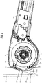
- the housing 7 is around an in Figure 3
- the indicated pivot axis 17 parallel to the winding shaft is mounted pivotably on the associated wall brackets 15.
- the front end regions of the guide rails 10 are each connected to the support structure formed here by the supports 16 via a tilting axis 18 containing tilting axes 18 parallel to the winding shaft.
- the for the patio roof awning according to Figures 1 and 2 Required support feet 11 are not required here and can therefore be removed.
- the wall brackets 15 and tilting joints 16 are used here as supporting elements.
- the plate-shaped or tab-shaped wall brackets 15, which can be fixed to the wall 14 via screws (not shown in detail), are, as best, from Figure 4 can be seen, in the area of its lower edge with a bearing block 20 protruding from its side remote from the wall for pivotably receiving a respectively associated two-armed pivoting piece 22 that engages in the bearing block 20, ie has a flag-like hinge part 21.
- the bearing block 20 and the hinge part 21 assigned to it are pivotably connected to one another by a pivot pin 17a which extends through these two organs and contains the pivot axis 17 and is parallel to the winding shaft.
- the housing 7 of the awning is on the swivel pieces 22 of the wall brackets 5, of which several, at least two, over the length of the housing can be provided, added.
- the pivoting piece 22 of each wall bracket 15 is designed as a shell element that encompasses a facing, rear housing area of the housing 7.
- the pivoting piece 22 is designed as a half-shell or part-shell that encompasses the rear, lower corner region of the housing 7 and against which the housing 7 rests snugly.
- the half or partial shell forming the pivot piece 22 has two arms 23, 24, which run away from the pivot bearing in opposite directions, namely an upper arm 23 and a lower arm 24.This is the upper end of the upper arm 23 of the pivot pieces 22 of the wall brackets 15 Housing 7 can be suspended.
- a hook-in claw 25 formed by a bend pointing backwards is provided at the upper end of the upper arm 23.
- the housing 7 is assigned to the upper end of the swivel piece 22, the rear area is provided with a corresponding undercut hooking groove 26 assigned to the hanging claw 25, which runs through the entire length of the housing, so that the swivel pieces 22 of all the wall brackets 15 provided, regardless of their lateral spacing and their distribution over the length of the housing can be brought into engagement in the same way.
- a stop device limiting the pivoting angle of the pivoting pieces 22 with respect to the wall brackets 15 is provided.
- the hinge part 21 of the swivel pieces 22 formed by a rear thickening is provided with a stop element 27 formed by a radial projection, which interacts with a facing mating surface, here in the form of the groove base of the associated bearing block 20, of the associated wall bracket 15.
- the stop element 27 is located in lower circumferential area of the hinge part 21 and is dimensioned in height so that a maximum pivot angle of 45 ° with respect to the housing wall 14, ie with respect to the wall brackets 15 attached to the housing wall 14, is possible. This results, on the one hand, in a sufficiently large adjustment range for setting the desired inclination of the awning 12 and, on the other hand, in the lower end position of the awning 12 in a favorable position for further assembly work to secure the housing 7 on the swivel pieces 22 of the wall brackets 15.
- the pivot pieces 22 of the wall brackets 15 are screwed to the housing 7.
- the housing 7 is provided with a T-groove 28, which is removed from the hanging groove 26 and is provided over the entire length of the housing, in which slot nuts 29 assigned to the wall brackets 15 can be accommodated, each of which has a threaded hole, and by means of a threaded hole that can be screwed into it. on the associated pivot piece 22 engaging, advantageously this penetrating screw 30 are firmly screwed herewith.
- This screw connection is expediently assigned to the lower arm 24 of the pivot pieces 22.
- the T-groove 28 is accordingly located in a lower circumferential area of the housing 7 associated with the lower arms 24 of the pivot pieces 22.
- the front end of the lower arm 24 of the pivot pieces 22 is tapered in thickness towards its free end, so that a approximately tangentially into the curved, lower circumferential contour of the housing 7 results in running contour.
- the awning which is pivotably received on the associated wall brackets 15 in the region of its rear end, is pivotably received at the front via the tilting joints 19 on the associated support device, which is formed here by the posts 16. This pivotability provided at the front and rear enables a self-adjusting adjustment of the inclination of the awning 12 to the structural conditions found.
- the tilting joints 19 assigned to the front end regions of the guide rails 10 are, as best shown, from Figure 5 can be seen as two-legged Hinge joints formed, the upper and lower legs of which are pivotally connected to each other by a winding shaft parallel, the tilt axis 18 containing bearing pin 18a and the upper leg 31 similar to the support feet 11 can be detachably screwed to the associated guide rail 10, while the lower leg 32 remains on the associated Support device attached or can also be detachably attachable thereto.
Landscapes
- Engineering & Computer Science (AREA)
- Architecture (AREA)
- Civil Engineering (AREA)
- Structural Engineering (AREA)
- Building Awnings And Sunshades (AREA)
Description
Die Erfindung betrifft eine Markise mit einem auf einer in einem Gehäuse angeordneten Wickelwelle aufgenommenen Markisentuch, das mit seinem vorderen Ende an einem Zugprofil angebracht ist, das mit seinen seitlichen Endbereichen in in Ausfallrichtung des Markisentuchs verlaufenden, vom an diesen angebrachten Gehäuse abstehenden Führungsschienen geführt ist, die zur Bildung einer Terrassendachmarkise über lösbar anbringbare Stützen auf einem Terrassendach aufgenommen sind.The invention relates to an awning with an awning fabric accommodated on a winding shaft arranged in a housing, the front end of which is attached to a tension profile which, with its lateral end regions, is guided in guide rails extending in the direction of the awning fabric and protruding from the housing attached thereto, which are added to the formation of a patio roof awning via releasably attachable supports on a patio roof.
Eine Terrassendachmarkise dieser Art ist beispielsweise aus der
Hiervon ausgehend ist es daher die Aufgabe der vorliegenden Erfindung, mit einfachen und kostengünstigen Mitteln auch eine alternative Verwendung einer Markise gattungsgemäßer Art als eine Freifläche etc. übergreifende Pergolamarkise zu ermöglichen.Based on this, it is therefore the object of the present invention to also enable an alternative use of an awning of the generic type as a pergola awning that extends over an open area etc. with simple and inexpensive means.
Diese Aufgabe wird dadurch gelöst, dass die Führungsschienen zur Bildung einer Pergolamarkise ohne die Stützen nur im Bereich ihrer vorderen Enden lösbar an das obere Ende einer jeweils zugeordneten Abstützung angeschlossen sind und dass das Gehäuse auf lösbar hieran angebrachten Wandkonsolen aufgenommen ist, die jeweils ein um eine wickelwelleparallele Achse schwenkbar gelagertes Schwenkstück aufweisen, das als einen zugewandten, hinteren Bereich des Gehäuses umgreifende, lösbar hieran festgelegte Teilschale ausgebildet ist.This object is achieved in that the guide rails for forming a pergola awning without the supports can only be detached in the area of their front ends the upper end of a respectively assigned support are connected and that the housing is accommodated on detachably attached wall brackets, each of which has a pivoting piece pivotably mounted about an axis parallel to the winding shaft, which is designed as a partial shell that encompasses a facing, rear region of the housing and is detachably attached to it .
Diese Maßnahmen erweitern unter Zuhilfenahme lediglich weniger Zusatzbauteile das Einsatzgebiet der erfindungsgemäßen Markise, was eine Herstellung in größeren Chargen ermöglicht und die Lagerhaltung vereinfacht und damit insgesamt eine gute Wirtschaftlichkeit gewährleistet. Bei der Montage der erfindungsgemäßen Markise als Pergolamarkise kann das die Wickelwelle enthaltende Gehäuse einfach zum Eingriff mit den Schwenkstücken der bereits vormontierten Wandkonsolen gebracht werden, was bereits einen vorläufigen Halt der gesamten, aus Gehäuse und hieran angebrachten Führungsschinen bestehenden Baueinheit ergibt und damit deren endgültige Montage erleichtert.With the aid of only a few additional components, these measures expand the field of application of the awning according to the invention, which enables production in larger batches and simplifies storage and thus ensures good economy overall. When assembling the awning according to the invention as a pergola awning, the housing containing the winding shaft can simply be brought into engagement with the swivel pieces of the already pre-assembled wall brackets, which already results in a temporary hold of the entire unit consisting of the housing and guide rails attached to it and thus facilitates its final assembly .
Vorteilhafte Ausgestaltungen und zweckmäßige Fortbildungen der übergeordneten Maßnahmen sind in den Unteransprüchen angegeben.Advantageous refinements and expedient further developments of the superordinate measures are specified in the subclaims.
So kann den Schwenkstücken jeweils eine ihren Schwenkwinkel gegenüber der zugeordneten Wandkonsole begrenzende Anschlageinrichtung zugeordnet sein. Hierdurch wird sichergestellt, dass die mit ihrem Gehäuse in die Schwenkstücke eingehängte Markise bereits so gehalten wird, dass sie nicht herunter fallen kann und eine bequeme Verschraubung des Gehäuses mit den Schwenkstücken erfolgen kann, was den Gesamtmontagevorgang erleichtert.Thus, the pivoting pieces can each be assigned a stop device limiting their pivoting angle with respect to the assigned wall bracket. This ensures that the awning, which is hung with its housing in the swivel pieces, is already held in such a way that it cannot fall down and the housing can be easily screwed to the swivel pieces, which simplifies the overall assembly process.
Vorteilhaft weisen die Schwenkstücke jeweils eine durch eine rückwärtige Verdickung gebildete, einem konsolenseitig vorgesehenen Lagerbock zugeordnete und durch einen wickelwellenparallelen Lagerstift hiermit verbundene Lagerfahne auf, die in ihrem unteren Umfangsbereich mit einem tangentialen Vorsprung versehen ist, der zur Bildung einer Anschlageinrichtung mit einer konsolenseitigen Gegenfläche zusammenwirkt. Diese Maßnahmen ergeben eine einfache Integration der Anschlageinrichtung in die Schwenklagerung der Schwenkstücke und damit insgesamt eine einfache Bauweise. Gleichzeitig ist hierdurch sichergestellt, dass die Anschlageinrichtung automatisch wirksam wird.Advantageously, the pivoting pieces each have a bearing vane formed by a rear thickening, assigned to a bearing block provided on the console side and connected to it by a bearing pin parallel to the winding shaft, which is provided in its lower circumferential area with a tangential projection, which to form a stop device with a console-side Counter surface cooperates. These measures result in a simple integration of the stop device into the pivot mounting of the pivot pieces and thus an overall simple design. At the same time, this ensures that the anchor device is automatically effective.
In weiterer Fortbildung der übergeordneten Maßnahmen können die vorderen Enden der Führungsschienen jeweils über ein eine wickelwellenparallele Kippachse endhaltendes Kippgelenk an das obere Ende eines zugeordneten Pfostens oder dergleichen anschließbar sein. Die Kippgelenke ergeben zusammen mit der schwenkbaren Lagerung der Schwenkstücke eine hohe Variabilität hinsichtlich der Neigung der so erstellten Pergolamarkise und gewährleisten damit eine einfache Anpassbarkeit an vor Ort vorgefundene, bauliche Gegebenheiten.In a further development of the superordinate measures, the front ends of the guide rails can each be connected to the upper end of an assigned post or the like via a tilting joint holding a tilting axis parallel to the winding shaft. The tilting joints, together with the pivoting mounting of the pivoting pieces, result in a high degree of variability with regard to the inclination of the pergola awning created in this way and thus ensure easy adaptability to structural conditions found on site.
Eine weitere vorteilhafte Ausgestalltung kann darin bestehen, dass die die Schwenkstücke bildenden Teilschalen jeweils als zweiarmige Schwenkhebel mit von ihrem Schwenklager gegenläufig abgehenden Armen ausgebildet sind, wobei das obere Ende des oberen Arms eine eine Einhängklaue bildende, rückwärtige Abwinkung aufweist und wobei das Gehäuse in seinem dem oberen Ende des oberen Arms der Schwenkhebel zugeordneten Umfangsbereich eine hinterschnittene, durchgehende Einhängnut aufweist, in welche die Schwenkstücke mit ihren Einhängklauen einhängbar sind. Diese Maßnahmen gewährleisten eine einfache, vorläufige Sicherung der Markise durch Einhängen des Gehäuses an den Schwenkstücken, so dass anschließend eine bequeme endgültige Sicherung erfolgen kann.A further advantageous embodiment can consist in the fact that the partial shells forming the swivel pieces are each designed as two-armed swivel levers with arms extending in opposite directions from their swivel bearing, the upper end of the upper arm having a rear bend that forms a hook-in claw and the housing in its The upper end of the upper arm of the swivel lever associated peripheral region has an undercut, continuous hanging groove into which the swivel pieces can be hung with their hanging claws. These measures ensure a simple, preliminary securing of the awning by hanging the housing on the swivel pieces, so that a convenient final securing can then take place.
Hierzu kann das Gehäuse eine von der Einhängnut entfernte, durchgehende T-Nut aufweisen, in welcher den Schwenkstücken zugeordnete Nutensteine aufnehmbar sind, die mit einer Gewindebohrung versehen sind, in welche jeweils eine am zugeordneten Schwenkstück angreifene Halteschraube einschraubbar ist, wodurch eine feste Verbindung hergestellt wird. Zweckmäßig kann die Verschraubung im Bereich der unteren Arme der Schwenkstücke vorgesehen sein.For this purpose, the housing can have a continuous T-groove removed from the hanging groove, in which the sliding blocks assigned to the pivoting pieces can be accommodated, which are provided with a threaded hole into which a retaining screw engaged on the assigned pivoting piece can be screwed, whereby a fixed connection is established . The Screw connection can be provided in the area of the lower arms of the swivel pieces.
Vorteilhaft können die unteren Arme der Schwenkstücke zu ihrem Ende hin in der Dicke verjüngt sein, so dass sich eine schlanke Ausbildung der den zugewandten Gehäusebereich umfassenden, die Schwenkstücke bildenden Teilschalen ergibt.The lower arms of the pivoting pieces can advantageously be tapered in thickness towards their end, so that the result is a slim design of the partial shells that encompass the facing housing area and form the pivoting pieces.
Da die Einhängnut und T-Nut des Gehäuses als über die Länge durchgehende Nuten ausgebildet sind, kann die Anzahl der zum Einsatz kommenden Wandkonsolen in Abhängigkeit von der Länge des Gehäuses frei gewählt werden. Mindestens zwei Wandkonsolen sind im jedem Fall vorgesehen. Bei einer größeren Gehäuselänge können aber auch mehrere, gleichmäßige über die Länge verteilte Wandkonsolen vorgesehen sein.Since the hanging groove and T-groove of the housing are designed as grooves that extend over the length, the number of wall brackets used can be freely selected depending on the length of the housing. At least two wall brackets are always provided. With a larger housing length, however, several wall brackets evenly distributed over the length can be provided.
Weitere vorteilhafte Ausgestaltungen und zweckmäßige Fortbildungen der übergeordneten Maßnahmen sind in den restlichen Unteransprüchen angegeben und aus der nachstehenden Beispielsbeschreibung anhand der Zeichnung näher entnehmbar.Further advantageous refinements and expedient developments of the superordinate measures are specified in the remaining subclaims and can be taken from the following description of the example with reference to the drawing.
In der nachstehend beschriebenen Zeichnung zeigen:
- Figur 1
- eine perspektivische Ansicht einer erfindungsgemäßen Markise als Terrassendachmarkise,
Figur 2- eine Seitenansicht der Anordnung gemäß
Figur 1 , Figur 3- eine Seitenansicht einer erfindungsgemäßen Markise als Pergolamarkise,
- Figur 4
- eine vergrößerte Darstellung des rückwärtigen Bereichs der Anordnung gemäß
Figur 3 Figur 5- eine vergrößerte Darstellung des vorderen Bereichs der Anordnung gemäß
Figur 3
- Figure 1
- a perspective view of an awning according to the invention as a patio roof awning,
- Figure 2
- a side view of the arrangement according to
Figure 1 , - Figure 3
- a side view of an awning according to the invention as a pergola awning,
- Figure 4
- an enlarged view of the rear area of the arrangement according to
Figure 3 without housing cover and - Figure 5
- an enlarged view of the front area of the arrangement according to
Figure 3 .
In den
Diese enthält ein auf einer in den
Zur Erweiterung des Einsatzgebiets der den
Die über nicht näher dargestellte Schrauben an der Wand 14 festlegbaren, platten- oder laschenförmigen Wandkonsolen 15 sind, wie am besten aus
Im dargestellten Beispiel ist das Schwenkstück 22 als den hinteren, unteren Eckbereich des Gehäuses 7 umfassende Halb- bzw. Teilschale ausgebildet, an der das Gehäuse 7 satt anliegt. Die das Schwenkstück 22 bildende Halb- bzw. Teilschale besitzt zwei Arme 23, 24, die gegenläufig von der Schwenklagerung weglaufen, nämlich einen oberen Arm 23 und einen unteren Arm 24. Am oberen Ende des oberen Arms 23 der Schwenkstücke 22 der Wandkonsolen 15 ist das Gehäuse 7 einhängbar. Hierzu ist am oberen Ende des oberen Arms 23 eine durch eine nach hinten weisende Abwinklung gebildete Einhängklaue 25 vorgesehen. Das Gehäuse 7 ist im dem oberen Ende des Schwenkstücks 22 zugeordnet, rückwärtigen Bereich mit einer der Einhängklaue 25 zugeordneten, entsprechend hinterschnittenen Einhängnut 26 versehen, die über die ganze Gehäuselänge durchgeht, so dass die Schwenkstücke 22 sämtlicher vorgesehener Wandkonsolen 15 unabhängig von ihrem seitlichen Abstand und ihrer Verteilung über die Gehäuselänge in gleicher Weise zum Eingriff gebracht werden können.In the example shown, the pivoting
Durch Einhängung des Gehäuses 7 an den oberen Enden der Schwenkstücke 22 ergibt sich bereits eine lose Aufhängung des Gehäuses 7 und dementsprechend der gesamten Markise. Um dabei einem Absturz vorzubeugen ist eine den Schwenkwinkel der Schwenkstücke 22 gegenüber den Wandkonsolen 15 begrenzende Anschlageinrichtung vorgesehen. Hierzu ist im dargestellten Beispiel das durch eine rückwärtige Verdickung gebildete Scharnierteil 21 der Schwenkstücke 22 mit einem durch einen radialen Vorsprung gebildeten Anschlagelement 27 versehen, das mit einer zugewandten Gegenfläche, hier in Form des Nutgrunds des zugeordneten Lagerbocks 20, der zugeordneten Wandkonsole 15 zusammenwirkt. Das Anschlagelement 27 befindet sich im unteren Umfangsbereich des Scharnierteils 21 und ist in der Höhe so bemessen, dass ein maximaler Schwenkwinkel von 45° gegenüber der Gehäusewand 14, d. h. gegenüber den an der Gehäusewand 14 angebrachten Wandkonsolen 15 möglich ist. Hierdurch ergibt sich einerseits ein ausreichend großer Einstellbereich zur Einstellung der gewünschten Neigung der Markise 12 und andererseits in der unteren Endstellung eine günstige Position der Markise 12 für weitere Montagearbeiten zur sicheren Befestigung des Gehäuses 7 auf den Schwenkstücken 22 der Wandkonsolen 15.By hanging the
Hierzu findet eine Verschraubung der Schwenkstücke 22 der Wandkonsolen 15 mit dem Gehäuse 7 statt. Hierzu ist das Gehäuse 7 mit einer von der Einhängnut 26 entfernten, wie diese über die ganze Gehäuselänge durchgehenden T-Nut 28 versehen, in der den Wandkonsolen 15 zugeordnete Nutensteine 29 aufnehmbar sind, die jeweils eine Gewindebohrung aufweisen, und mittels einer in diese eindrehbaren, am zugeordneten Schwenkstück 22 angreifenden, vorteilhaft dieses durchgreifenden Schraube 30 fest hiermit verschraubbar sind. Diese Verschraubung ist zweckmäßig dem unteren Arm 24 der Schwenkstücke 22 zugeordnet. Die T-Nut 28 befindet sich dementsprechend in einem den unteren Armen 24 der Schwenkstücke 22 zugeordneten, unteren Umfangsbereich des Gehäuses 7. Das vordere Ende des unteren Arms 24 der Schwenkstücke 22 ist zu seinem freien Ende hin in der Dicke verjüngt, so dass sich eine etwa tangential in die gewölbte, untere Umfangskontur des Gehäuses 7 einlaufende Kontur ergibt.For this purpose, the
Die im Bereich ihres hinteren Endes schwenkbar auf den zugeordneten Wandkonsolen 15 aufgenommene Markise ist vorne über die Kippgelenkte 19 schwenkbar an der zugeordneten, hier durch die Pfosten 16 gebildeten Stützeinrichtung aufgenommen. Diese hinten und vorne vorgesehene Schwenkbarkeit ermöglicht eine sich selbst einstellende Anpassung der Neigung der Markise 12 an die vorgefundenen, baulichen Gegebenheiten. Die den vorderen Endbereichen der Führungsschienen 10 zugeordneten Kippgelenke 19 sind, wie am besten aus
Die Zeichnungen lassen in Verbindung mit der obigen Beschreibung erkennen, dass ein und dieselbe Markise sowohl als Terrassendachmarkise 6 als auch als Pergolamarkise 12 verwendbar ist, wobei bei der Verwendung als Terrassendachmarkise lediglich die Stützfüße 11 und bei der Verwendung als Pergolamarkise lediglich die mit jeweils einem Schwenkstück 22 versehenen Wandkonsolen 15 und die Kippgelenke 19 als alternative Hilfselemente zum Einsatz kommen.The drawings, in conjunction with the above description, show that one and the same awning can be used both as a
Claims (9)
- An awning comprising an awning cloth received on a wrapping bale received in a housing (7), the front end of the said awning cloth being attached to a tension profile (9) whose lateral end regions are guided in guide rails (10) extending in the extension direction of the awning cloth and protruding from the housing (7) attached to the said end regions, such guide rails (10), for the purpose of forming a terrace roof awning (6), being received on a terrace roof via detachably attached struts (11), characterized in that the guide rails (10), for the purpose of forming a pergola awning (12) without the struts (11), are detachably attached to the upper end of each associated support only in the region of its front ends, and that the housing (7) is received on wall brackets (15) detachably attached therewith, each of the said wall brackets (15) exhibiting a swivel piece (22) swivel-mounted about an axis parallel to the wrapping shaft, such swivel piece (22) being designed as a partial bowl encompassing a facing rear part of the housing (7) and detachably attached to the latter.
- An awning in accordance with claim 1, characterized in that a stop section is associated with each of the swivel pieces (22) of the wall brackets (15) limiting their swivel angle relative to the associated wall bracket (15).
- An awning in accordance with claim 2, characterized in that the swivel pieces (22) comprise a bearing ear (21) formed by a rear thickening, associated with a bracket-side bearing bracket (20) and connected therewith by a bearing pin (17a) parallel to the wrapping bale, such bearing ear (21) in its bottom circumferential area being provided with a tangential projection (27) which for the purpose of forming a stop device acts together with a bracket-side counter surface.
- An awning in accordance with any of the preceding claims, characterized in that each of the front ends of the guide rails (10) is connectable with the upper end of an associated post (16) etc. by means of a tilt joint (19) comprising a tilt axis parallel to the wrapping shaft.
- An awning in accordance with any of the preceding claims, characterized in that each partial bowl forming a swivel piece (22) is designed as a two arm lever comprising arms (23), (24) extending from their swivel bearing in a counter direction, with the upper end of the upper arm (23) exhibiting a rear deflection forming a suspension claw (25) and that the housing (7) in its circumferential area associated with the upper end of the upper arm (23) is provided with a correspondingly undercut, continuous suspension groove (26) in which the swivel pieces (22) of all wall brackets (15) are mountable with their suspension claws (25).
- An awning in accordance with any of the preceding claims, characterized in that the housing (7) comprises a continuous T-groove (28) away from the suspension groove (26) in which groove stones (29), associated with the swivel pieces (22) of the suspension brackets (15), are receivable, such groove stones (29) being provided with a tapped hole in which a holding screw (30) can be screwed and acts on each associated swivel piece (22).
- An awning in accordance with claim 6, characterized in that the T-groove (28) is associated with the bottom circumferential area of the housing (7) contacting the bottom arm (24) of the swivel pieces (22).
- An awning in accordance with any of the preceding claims, characterized in that the bottom arm (24) of the swivel pieces (22) is tapered in its thickness towards its free end.
- An awning in accordance with any of the preceding claims, characterized in that the suspension groove (26) and T-groove (28) of the housing (7) extend across the housing length and that several wall brackets (15) are provided across the housing length.
Applications Claiming Priority (1)
| Application Number | Priority Date | Filing Date | Title |
|---|---|---|---|
| DE202017005991.6U DE202017005991U1 (en) | 2017-11-20 | 2017-11-20 | awning |
Publications (3)
| Publication Number | Publication Date |
|---|---|
| EP3486397A1 EP3486397A1 (en) | 2019-05-22 |
| EP3486397B1 true EP3486397B1 (en) | 2020-09-23 |
| EP3486397B2 EP3486397B2 (en) | 2024-08-21 |
Family
ID=60782760
Family Applications (1)
| Application Number | Title | Priority Date | Filing Date |
|---|---|---|---|
| EP18020594.0A Active EP3486397B2 (en) | 2017-11-20 | 2018-11-13 | Awning |
Country Status (3)
| Country | Link |
|---|---|
| EP (1) | EP3486397B2 (en) |
| DE (1) | DE202017005991U1 (en) |
| ES (1) | ES2830772T5 (en) |
Families Citing this family (2)
| Publication number | Priority date | Publication date | Assignee | Title |
|---|---|---|---|---|
| DE202019002242U1 (en) | 2019-05-22 | 2019-06-07 | Erhardt Markisenbau Gmbh | Device for shading an open space |
| DE102020134445A1 (en) | 2020-12-21 | 2022-06-23 | Warema Renkhoff Se | Carrying bracket with pivoting bearing for attaching a housing of a sun protection system |
Citations (7)
| Publication number | Priority date | Publication date | Assignee | Title |
|---|---|---|---|---|
| DE10150709C2 (en) | 2001-10-13 | 2003-12-11 | Erhardt Markisenbau Gmbh | awning |
| DE10233144A1 (en) | 2002-07-19 | 2004-02-05 | Weinor Dieter Weiermann Gmbh & Co. | Extendable sun protection |
| DE202007006874U1 (en) | 2007-05-12 | 2007-07-19 | Schmitz-Werke Gmbh + Co. Kg | Conservatory awning and cleaning device for a conservatory glazing |
| DE202010011307U1 (en) | 2009-08-31 | 2010-11-04 | Schmitz-Werke Gmbh + Co Kg | Free-standing roofing in the manner of a conservatory awning |
| EP2631393A1 (en) | 2009-05-19 | 2013-08-28 | Pacadar S.A. | A tower for a wind turbine |
| DE202015001293U1 (en) | 2015-02-20 | 2015-03-16 | Weinor Gmbh & Co. Kg | Awning with adjustable vertical supports |
| DE202015001731U1 (en) | 2014-03-05 | 2015-03-26 | Gibus S.P.A. | Awning for outdoor areas |
Family Cites Families (1)
| Publication number | Priority date | Publication date | Assignee | Title |
|---|---|---|---|---|
| NL2008366C2 (en) * | 2012-02-27 | 2013-08-28 | Lewens Sonnenschutz Systeme Gmbh & Co Kg | CONSTRUCTION. |
-
2017
- 2017-11-20 DE DE202017005991.6U patent/DE202017005991U1/en active Active
-
2018
- 2018-11-13 EP EP18020594.0A patent/EP3486397B2/en active Active
- 2018-11-13 ES ES18020594T patent/ES2830772T5/en active Active
Patent Citations (7)
| Publication number | Priority date | Publication date | Assignee | Title |
|---|---|---|---|---|
| DE10150709C2 (en) | 2001-10-13 | 2003-12-11 | Erhardt Markisenbau Gmbh | awning |
| DE10233144A1 (en) | 2002-07-19 | 2004-02-05 | Weinor Dieter Weiermann Gmbh & Co. | Extendable sun protection |
| DE202007006874U1 (en) | 2007-05-12 | 2007-07-19 | Schmitz-Werke Gmbh + Co. Kg | Conservatory awning and cleaning device for a conservatory glazing |
| EP2631393A1 (en) | 2009-05-19 | 2013-08-28 | Pacadar S.A. | A tower for a wind turbine |
| DE202010011307U1 (en) | 2009-08-31 | 2010-11-04 | Schmitz-Werke Gmbh + Co Kg | Free-standing roofing in the manner of a conservatory awning |
| DE202015001731U1 (en) | 2014-03-05 | 2015-03-26 | Gibus S.P.A. | Awning for outdoor areas |
| DE202015001293U1 (en) | 2015-02-20 | 2015-03-16 | Weinor Gmbh & Co. Kg | Awning with adjustable vertical supports |
Non-Patent Citations (1)
| Title |
|---|
| "Plaza Viva - die textile Pergola-Markise", PREISLISTE UND TECHNISCHE INFORMATIONEN 2017, 10 April 2017 (2017-04-10), pages 1 - 10, 14, 34, XP055820241 |
Also Published As
| Publication number | Publication date |
|---|---|
| DE202017005991U1 (en) | 2017-12-07 |
| ES2830772T5 (en) | 2025-01-29 |
| EP3486397A1 (en) | 2019-05-22 |
| EP3486397B2 (en) | 2024-08-21 |
| ES2830772T3 (en) | 2021-06-04 |
Similar Documents
| Publication | Publication Date | Title |
|---|---|---|
| EP3341538B1 (en) | Fanned vehicle awning | |
| EP0176973B1 (en) | Bollard mount | |
| EP3486397B1 (en) | Awning | |
| DE2609824A1 (en) | DEVICE FOR FASTENING ROLL-UP AWNINGS | |
| DE102012107453A1 (en) | Folding shower seat attached to wall of shower room, has attachable vertical wall support whose lower portion has support seat at desired height that engages with opposite supports that are supported in vertically downward direction | |
| DE1659340B2 (en) | LOCAL CORNER CLADDING FOR FLAT ROOFS OR DGL | |
| DE102011121548B4 (en) | Fastening element, fastening arrangement and roofing | |
| DE3406027C2 (en) | Swiveling window sill | |
| DE4439788C1 (en) | Awning with articulated arms | |
| EP2574257B1 (en) | Window decoration | |
| EP1104829B1 (en) | Boxed awning | |
| DE29811284U1 (en) | Roof construction with eaves | |
| DE1256392B (en) | Verge cladding for flat roofs | |
| DE2909306A1 (en) | AWNING | |
| DE2544154A1 (en) | Swivel mounting support for TV receiver - has retaining edges engaging over top and bottom of appliance preventing undue tilting | |
| DE8712683U1 (en) | Multiple swivel joint for tent poles | |
| DE102020134445A1 (en) | Carrying bracket with pivoting bearing for attaching a housing of a sun protection system | |
| DE4235998A1 (en) | Gutter bracket | |
| DE3512778C2 (en) | ||
| DE1709051B2 (en) | Verge cladding for flat roofs | |
| EP3985200A1 (en) | Mounting bracket for mounting an awning to a building and awning equipped with same | |
| DE202021105665U1 (en) | Support structure for a canopy | |
| DE202010003822U1 (en) | House canopy | |
| DE3329866A1 (en) | Roof structure | |
| DE202019002242U1 (en) | Device for shading an open space |
Legal Events
| Date | Code | Title | Description |
|---|---|---|---|
| PUAI | Public reference made under article 153(3) epc to a published international application that has entered the european phase |
Free format text: ORIGINAL CODE: 0009012 |
|
| STAA | Information on the status of an ep patent application or granted ep patent |
Free format text: STATUS: THE APPLICATION HAS BEEN PUBLISHED |
|
| STAA | Information on the status of an ep patent application or granted ep patent |
Free format text: STATUS: REQUEST FOR EXAMINATION WAS MADE |
|
| AK | Designated contracting states |
Kind code of ref document: A1 Designated state(s): AL AT BE BG CH CY CZ DE DK EE ES FI FR GB GR HR HU IE IS IT LI LT LU LV MC MK MT NL NO PL PT RO RS SE SI SK SM TR |
|
| AX | Request for extension of the european patent |
Extension state: BA ME |
|
| 17P | Request for examination filed |
Effective date: 20190508 |
|
| RBV | Designated contracting states (corrected) |
Designated state(s): AL AT BE BG CH CY CZ DE DK EE ES FI FR GB GR HR HU IE IS IT LI LT LU LV MC MK MT NL NO PL PT RO RS SE SI SK SM TR |
|
| STAA | Information on the status of an ep patent application or granted ep patent |
Free format text: STATUS: EXAMINATION IS IN PROGRESS |
|
| 17Q | First examination report despatched |
Effective date: 20191113 |
|
| GRAP | Despatch of communication of intention to grant a patent |
Free format text: ORIGINAL CODE: EPIDOSNIGR1 |
|
| STAA | Information on the status of an ep patent application or granted ep patent |
Free format text: STATUS: GRANT OF PATENT IS INTENDED |
|
| INTG | Intention to grant announced |
Effective date: 20200506 |
|
| GRAS | Grant fee paid |
Free format text: ORIGINAL CODE: EPIDOSNIGR3 |
|
| GRAA | (expected) grant |
Free format text: ORIGINAL CODE: 0009210 |
|
| STAA | Information on the status of an ep patent application or granted ep patent |
Free format text: STATUS: THE PATENT HAS BEEN GRANTED |
|
| AK | Designated contracting states |
Kind code of ref document: B1 Designated state(s): AL AT BE BG CH CY CZ DE DK EE ES FI FR GB GR HR HU IE IS IT LI LT LU LV MC MK MT NL NO PL PT RO RS SE SI SK SM TR |
|
| REG | Reference to a national code |
Ref country code: GB Ref legal event code: FG4D Free format text: NOT ENGLISH |
|
| REG | Reference to a national code |
Ref country code: CH Ref legal event code: EP |
|
| REG | Reference to a national code |
Ref country code: DE Ref legal event code: R096 Ref document number: 502018002497 Country of ref document: DE |
|
| REG | Reference to a national code |
Ref country code: IE Ref legal event code: FG4D Free format text: LANGUAGE OF EP DOCUMENT: GERMAN |
|
| REG | Reference to a national code |
Ref country code: CH Ref legal event code: NV Representative=s name: PATENTANWAELTE MUNK, DE Ref country code: AT Ref legal event code: REF Ref document number: 1316515 Country of ref document: AT Kind code of ref document: T Effective date: 20201015 |
|
| REG | Reference to a national code |
Ref country code: NL Ref legal event code: FP |
|
| REG | Reference to a national code |
Ref country code: GR Ref legal event code: EP Ref document number: 20200402830 Country of ref document: GR Effective date: 20201116 |
|
| PG25 | Lapsed in a contracting state [announced via postgrant information from national office to epo] |
Ref country code: NO Free format text: LAPSE BECAUSE OF FAILURE TO SUBMIT A TRANSLATION OF THE DESCRIPTION OR TO PAY THE FEE WITHIN THE PRESCRIBED TIME-LIMIT Effective date: 20201223 Ref country code: FI Free format text: LAPSE BECAUSE OF FAILURE TO SUBMIT A TRANSLATION OF THE DESCRIPTION OR TO PAY THE FEE WITHIN THE PRESCRIBED TIME-LIMIT Effective date: 20200923 Ref country code: HR Free format text: LAPSE BECAUSE OF FAILURE TO SUBMIT A TRANSLATION OF THE DESCRIPTION OR TO PAY THE FEE WITHIN THE PRESCRIBED TIME-LIMIT Effective date: 20200923 Ref country code: SE Free format text: LAPSE BECAUSE OF FAILURE TO SUBMIT A TRANSLATION OF THE DESCRIPTION OR TO PAY THE FEE WITHIN THE PRESCRIBED TIME-LIMIT Effective date: 20200923 Ref country code: BG Free format text: LAPSE BECAUSE OF FAILURE TO SUBMIT A TRANSLATION OF THE DESCRIPTION OR TO PAY THE FEE WITHIN THE PRESCRIBED TIME-LIMIT Effective date: 20201223 |
|
| PG25 | Lapsed in a contracting state [announced via postgrant information from national office to epo] |
Ref country code: LV Free format text: LAPSE BECAUSE OF FAILURE TO SUBMIT A TRANSLATION OF THE DESCRIPTION OR TO PAY THE FEE WITHIN THE PRESCRIBED TIME-LIMIT Effective date: 20200923 Ref country code: RS Free format text: LAPSE BECAUSE OF FAILURE TO SUBMIT A TRANSLATION OF THE DESCRIPTION OR TO PAY THE FEE WITHIN THE PRESCRIBED TIME-LIMIT Effective date: 20200923 |
|
| REG | Reference to a national code |
Ref country code: LT Ref legal event code: MG4D |
|
| PG25 | Lapsed in a contracting state [announced via postgrant information from national office to epo] |
Ref country code: LT Free format text: LAPSE BECAUSE OF FAILURE TO SUBMIT A TRANSLATION OF THE DESCRIPTION OR TO PAY THE FEE WITHIN THE PRESCRIBED TIME-LIMIT Effective date: 20200923 Ref country code: SM Free format text: LAPSE BECAUSE OF FAILURE TO SUBMIT A TRANSLATION OF THE DESCRIPTION OR TO PAY THE FEE WITHIN THE PRESCRIBED TIME-LIMIT Effective date: 20200923 Ref country code: EE Free format text: LAPSE BECAUSE OF FAILURE TO SUBMIT A TRANSLATION OF THE DESCRIPTION OR TO PAY THE FEE WITHIN THE PRESCRIBED TIME-LIMIT Effective date: 20200923 Ref country code: RO Free format text: LAPSE BECAUSE OF FAILURE TO SUBMIT A TRANSLATION OF THE DESCRIPTION OR TO PAY THE FEE WITHIN THE PRESCRIBED TIME-LIMIT Effective date: 20200923 Ref country code: PT Free format text: LAPSE BECAUSE OF FAILURE TO SUBMIT A TRANSLATION OF THE DESCRIPTION OR TO PAY THE FEE WITHIN THE PRESCRIBED TIME-LIMIT Effective date: 20210125 Ref country code: CZ Free format text: LAPSE BECAUSE OF FAILURE TO SUBMIT A TRANSLATION OF THE DESCRIPTION OR TO PAY THE FEE WITHIN THE PRESCRIBED TIME-LIMIT Effective date: 20200923 |
|
| PG25 | Lapsed in a contracting state [announced via postgrant information from national office to epo] |
Ref country code: IS Free format text: LAPSE BECAUSE OF FAILURE TO SUBMIT A TRANSLATION OF THE DESCRIPTION OR TO PAY THE FEE WITHIN THE PRESCRIBED TIME-LIMIT Effective date: 20210123 Ref country code: PL Free format text: LAPSE BECAUSE OF FAILURE TO SUBMIT A TRANSLATION OF THE DESCRIPTION OR TO PAY THE FEE WITHIN THE PRESCRIBED TIME-LIMIT Effective date: 20200923 Ref country code: AL Free format text: LAPSE BECAUSE OF FAILURE TO SUBMIT A TRANSLATION OF THE DESCRIPTION OR TO PAY THE FEE WITHIN THE PRESCRIBED TIME-LIMIT Effective date: 20200923 |
|
| REG | Reference to a national code |
Ref country code: ES Ref legal event code: FG2A Ref document number: 2830772 Country of ref document: ES Kind code of ref document: T3 Effective date: 20210604 |
|
| REG | Reference to a national code |
Ref country code: DE Ref legal event code: R026 Ref document number: 502018002497 Country of ref document: DE |
|
| PLBI | Opposition filed |
Free format text: ORIGINAL CODE: 0009260 |
|
| PLAB | Opposition data, opponent's data or that of the opponent's representative modified |
Free format text: ORIGINAL CODE: 0009299OPPO |
|
| PG25 | Lapsed in a contracting state [announced via postgrant information from national office to epo] |
Ref country code: MC Free format text: LAPSE BECAUSE OF FAILURE TO SUBMIT A TRANSLATION OF THE DESCRIPTION OR TO PAY THE FEE WITHIN THE PRESCRIBED TIME-LIMIT Effective date: 20200923 Ref country code: SK Free format text: LAPSE BECAUSE OF FAILURE TO SUBMIT A TRANSLATION OF THE DESCRIPTION OR TO PAY THE FEE WITHIN THE PRESCRIBED TIME-LIMIT Effective date: 20200923 |
|
| PLAX | Notice of opposition and request to file observation + time limit sent |
Free format text: ORIGINAL CODE: EPIDOSNOBS2 |
|
| 26 | Opposition filed |
Opponent name: WEINOR GMBH & CO. KG Effective date: 20210617 |
|
| R26 | Opposition filed (corrected) |
Opponent name: WEINOR GMBH & CO. KG Effective date: 20210617 |
|
| PG25 | Lapsed in a contracting state [announced via postgrant information from national office to epo] |
Ref country code: LU Free format text: LAPSE BECAUSE OF NON-PAYMENT OF DUE FEES Effective date: 20201113 |
|
| PLBB | Reply of patent proprietor to notice(s) of opposition received |
Free format text: ORIGINAL CODE: EPIDOSNOBS3 |
|
| PG25 | Lapsed in a contracting state [announced via postgrant information from national office to epo] |
Ref country code: SI Free format text: LAPSE BECAUSE OF FAILURE TO SUBMIT A TRANSLATION OF THE DESCRIPTION OR TO PAY THE FEE WITHIN THE PRESCRIBED TIME-LIMIT Effective date: 20200923 Ref country code: DK Free format text: LAPSE BECAUSE OF FAILURE TO SUBMIT A TRANSLATION OF THE DESCRIPTION OR TO PAY THE FEE WITHIN THE PRESCRIBED TIME-LIMIT Effective date: 20200923 |
|
| PG25 | Lapsed in a contracting state [announced via postgrant information from national office to epo] |
Ref country code: IE Free format text: LAPSE BECAUSE OF NON-PAYMENT OF DUE FEES Effective date: 20201113 |
|
| PG25 | Lapsed in a contracting state [announced via postgrant information from national office to epo] |
Ref country code: TR Free format text: LAPSE BECAUSE OF FAILURE TO SUBMIT A TRANSLATION OF THE DESCRIPTION OR TO PAY THE FEE WITHIN THE PRESCRIBED TIME-LIMIT Effective date: 20200923 Ref country code: MT Free format text: LAPSE BECAUSE OF FAILURE TO SUBMIT A TRANSLATION OF THE DESCRIPTION OR TO PAY THE FEE WITHIN THE PRESCRIBED TIME-LIMIT Effective date: 20200923 Ref country code: CY Free format text: LAPSE BECAUSE OF FAILURE TO SUBMIT A TRANSLATION OF THE DESCRIPTION OR TO PAY THE FEE WITHIN THE PRESCRIBED TIME-LIMIT Effective date: 20200923 |
|
| PG25 | Lapsed in a contracting state [announced via postgrant information from national office to epo] |
Ref country code: MK Free format text: LAPSE BECAUSE OF FAILURE TO SUBMIT A TRANSLATION OF THE DESCRIPTION OR TO PAY THE FEE WITHIN THE PRESCRIBED TIME-LIMIT Effective date: 20200923 |
|
| PLAY | Examination report in opposition despatched + time limit |
Free format text: ORIGINAL CODE: EPIDOSNORE2 |
|
| PLBC | Reply to examination report in opposition received |
Free format text: ORIGINAL CODE: EPIDOSNORE3 |
|
| PUAH | Patent maintained in amended form |
Free format text: ORIGINAL CODE: 0009272 |
|
| STAA | Information on the status of an ep patent application or granted ep patent |
Free format text: STATUS: PATENT MAINTAINED AS AMENDED |
|
| 27A | Patent maintained in amended form |
Effective date: 20240821 |
|
| AK | Designated contracting states |
Kind code of ref document: B2 Designated state(s): AL AT BE BG CH CY CZ DE DK EE ES FI FR GB GR HR HU IE IS IT LI LT LU LV MC MK MT NL NO PL PT RO RS SE SI SK SM TR |
|
| REG | Reference to a national code |
Ref country code: DE Ref legal event code: R102 Ref document number: 502018002497 Country of ref document: DE |
|
| REG | Reference to a national code |
Ref country code: NL Ref legal event code: FP |
|
| REG | Reference to a national code |
Ref country code: ES Ref legal event code: DC2A Ref document number: 2830772 Country of ref document: ES Kind code of ref document: T5 Effective date: 20250129 |
|
| REG | Reference to a national code |
Ref country code: GR Ref legal event code: EP Ref document number: 20240402393 Country of ref document: GR Effective date: 20250314 |
|
| REG | Reference to a national code |
Ref country code: CH Ref legal event code: U11 Free format text: ST27 STATUS EVENT CODE: U-0-0-U10-U11 (AS PROVIDED BY THE NATIONAL OFFICE) Effective date: 20251201 |
|
| PGFP | Annual fee paid to national office [announced via postgrant information from national office to epo] |
Ref country code: NL Payment date: 20251119 Year of fee payment: 8 |
|
| PGFP | Annual fee paid to national office [announced via postgrant information from national office to epo] |
Ref country code: DE Payment date: 20251130 Year of fee payment: 8 |
|
| PGFP | Annual fee paid to national office [announced via postgrant information from national office to epo] |
Ref country code: GB Payment date: 20251120 Year of fee payment: 8 |
|
| PGFP | Annual fee paid to national office [announced via postgrant information from national office to epo] |
Ref country code: AT Payment date: 20251117 Year of fee payment: 8 |
|
| PGFP | Annual fee paid to national office [announced via postgrant information from national office to epo] |
Ref country code: IT Payment date: 20251128 Year of fee payment: 8 |
|
| PGFP | Annual fee paid to national office [announced via postgrant information from national office to epo] |
Ref country code: FR Payment date: 20251120 Year of fee payment: 8 |
|
| PGFP | Annual fee paid to national office [announced via postgrant information from national office to epo] |
Ref country code: BE Payment date: 20251118 Year of fee payment: 8 Ref country code: GR Payment date: 20251117 Year of fee payment: 8 |
|
| PGFP | Annual fee paid to national office [announced via postgrant information from national office to epo] |
Ref country code: CH Payment date: 20251201 Year of fee payment: 8 |
|
| PGFP | Annual fee paid to national office [announced via postgrant information from national office to epo] |
Ref country code: ES Payment date: 20251216 Year of fee payment: 8 |