EP3475146B1 - Kugelgewindetrieb einer elektromechanischen servolenkung mit umlenkkörper für eine kugelrückführung - Google Patents
Kugelgewindetrieb einer elektromechanischen servolenkung mit umlenkkörper für eine kugelrückführung Download PDFInfo
- Publication number
- EP3475146B1 EP3475146B1 EP17731903.5A EP17731903A EP3475146B1 EP 3475146 B1 EP3475146 B1 EP 3475146B1 EP 17731903 A EP17731903 A EP 17731903A EP 3475146 B1 EP3475146 B1 EP 3475146B1
- Authority
- EP
- European Patent Office
- Prior art keywords
- ball
- power steering
- steering device
- electromechanical power
- webs
- Prior art date
- Legal status (The legal status is an assumption and is not a legal conclusion. Google has not performed a legal analysis and makes no representation as to the accuracy of the status listed.)
- Active
Links
- 239000004033 plastic Substances 0.000 description 6
- 230000005540 biological transmission Effects 0.000 description 4
- 239000000463 material Substances 0.000 description 4
- 230000002093 peripheral effect Effects 0.000 description 4
- 229920002302 Nylon 6,6 Polymers 0.000 description 2
- 230000008878 coupling Effects 0.000 description 2
- 238000010168 coupling process Methods 0.000 description 2
- 238000005859 coupling reaction Methods 0.000 description 2
- 238000006073 displacement reaction Methods 0.000 description 2
- 239000003365 glass fiber Substances 0.000 description 2
- 230000002787 reinforcement Effects 0.000 description 2
- 229910000831 Steel Inorganic materials 0.000 description 1
- XAGFODPZIPBFFR-UHFFFAOYSA-N aluminium Chemical compound [Al] XAGFODPZIPBFFR-UHFFFAOYSA-N 0.000 description 1
- 229910052782 aluminium Inorganic materials 0.000 description 1
- 230000008901 benefit Effects 0.000 description 1
- 238000006243 chemical reaction Methods 0.000 description 1
- 238000009826 distribution Methods 0.000 description 1
- 230000005489 elastic deformation Effects 0.000 description 1
- 238000001746 injection moulding Methods 0.000 description 1
- 238000005304 joining Methods 0.000 description 1
- 238000005461 lubrication Methods 0.000 description 1
- 238000004519 manufacturing process Methods 0.000 description 1
- 238000000034 method Methods 0.000 description 1
- 230000000149 penetrating effect Effects 0.000 description 1
- 230000008569 process Effects 0.000 description 1
- 238000005096 rolling process Methods 0.000 description 1
- 239000010959 steel Substances 0.000 description 1
- 230000007704 transition Effects 0.000 description 1
Images


Classifications
-
- B—PERFORMING OPERATIONS; TRANSPORTING
- B62—LAND VEHICLES FOR TRAVELLING OTHERWISE THAN ON RAILS
- B62D—MOTOR VEHICLES; TRAILERS
- B62D5/00—Power-assisted or power-driven steering
- B62D5/04—Power-assisted or power-driven steering electrical, e.g. using an electric servo-motor connected to, or forming part of, the steering gear
- B62D5/0442—Conversion of rotational into longitudinal movement
- B62D5/0445—Screw drives
- B62D5/0448—Ball nuts
-
- B—PERFORMING OPERATIONS; TRANSPORTING
- B62—LAND VEHICLES FOR TRAVELLING OTHERWISE THAN ON RAILS
- B62D—MOTOR VEHICLES; TRAILERS
- B62D5/00—Power-assisted or power-driven steering
- B62D5/04—Power-assisted or power-driven steering electrical, e.g. using an electric servo-motor connected to, or forming part of, the steering gear
- B62D5/0421—Electric motor acting on or near steering gear
- B62D5/0424—Electric motor acting on or near steering gear the axes of motor and final driven element of steering gear, e.g. rack, being parallel
-
- B—PERFORMING OPERATIONS; TRANSPORTING
- B62—LAND VEHICLES FOR TRAVELLING OTHERWISE THAN ON RAILS
- B62D—MOTOR VEHICLES; TRAILERS
- B62D3/00—Steering gears
- B62D3/02—Steering gears mechanical
- B62D3/12—Steering gears mechanical of rack-and-pinion type
- B62D3/126—Steering gears mechanical of rack-and-pinion type characterised by the rack
-
- B—PERFORMING OPERATIONS; TRANSPORTING
- B62—LAND VEHICLES FOR TRAVELLING OTHERWISE THAN ON RAILS
- B62D—MOTOR VEHICLES; TRAILERS
- B62D5/00—Power-assisted or power-driven steering
- B62D5/001—Mechanical components or aspects of steer-by-wire systems, not otherwise provided for in this maingroup
- B62D5/005—Mechanical components or aspects of steer-by-wire systems, not otherwise provided for in this maingroup means for generating torque on steering wheel or input member, e.g. feedback
- B62D5/006—Mechanical components or aspects of steer-by-wire systems, not otherwise provided for in this maingroup means for generating torque on steering wheel or input member, e.g. feedback power actuated
-
- F—MECHANICAL ENGINEERING; LIGHTING; HEATING; WEAPONS; BLASTING
- F16—ENGINEERING ELEMENTS AND UNITS; GENERAL MEASURES FOR PRODUCING AND MAINTAINING EFFECTIVE FUNCTIONING OF MACHINES OR INSTALLATIONS; THERMAL INSULATION IN GENERAL
- F16H—GEARING
- F16H25/00—Gearings comprising primarily only cams, cam-followers and screw-and-nut mechanisms
- F16H25/18—Gearings comprising primarily only cams, cam-followers and screw-and-nut mechanisms for conveying or interconverting oscillating or reciprocating motions
- F16H25/20—Screw mechanisms
- F16H25/22—Screw mechanisms with balls, rollers, or similar members between the co-operating parts; Elements essential to the use of such members
- F16H25/2204—Screw mechanisms with balls, rollers, or similar members between the co-operating parts; Elements essential to the use of such members with balls
- F16H25/2214—Screw mechanisms with balls, rollers, or similar members between the co-operating parts; Elements essential to the use of such members with balls with elements for guiding the circulating balls
- F16H25/2219—Axially mounted end-deflectors
-
- F—MECHANICAL ENGINEERING; LIGHTING; HEATING; WEAPONS; BLASTING
- F16—ENGINEERING ELEMENTS AND UNITS; GENERAL MEASURES FOR PRODUCING AND MAINTAINING EFFECTIVE FUNCTIONING OF MACHINES OR INSTALLATIONS; THERMAL INSULATION IN GENERAL
- F16H—GEARING
- F16H19/00—Gearings comprising essentially only toothed gears or friction members and not capable of conveying indefinitely-continuing rotary motion
- F16H19/02—Gearings comprising essentially only toothed gears or friction members and not capable of conveying indefinitely-continuing rotary motion for interconverting rotary or oscillating motion and reciprocating motion
- F16H19/04—Gearings comprising essentially only toothed gears or friction members and not capable of conveying indefinitely-continuing rotary motion for interconverting rotary or oscillating motion and reciprocating motion comprising a rack
-
- F—MECHANICAL ENGINEERING; LIGHTING; HEATING; WEAPONS; BLASTING
- F16—ENGINEERING ELEMENTS AND UNITS; GENERAL MEASURES FOR PRODUCING AND MAINTAINING EFFECTIVE FUNCTIONING OF MACHINES OR INSTALLATIONS; THERMAL INSULATION IN GENERAL
- F16H—GEARING
- F16H25/00—Gearings comprising primarily only cams, cam-followers and screw-and-nut mechanisms
- F16H25/18—Gearings comprising primarily only cams, cam-followers and screw-and-nut mechanisms for conveying or interconverting oscillating or reciprocating motions
- F16H25/20—Screw mechanisms
- F16H2025/2062—Arrangements for driving the actuator
- F16H2025/2096—Arrangements for driving the actuator using endless flexible members
Definitions
- the present invention relates to an electromechanical power steering system having the features of the preamble of claim 1.
- an electric motor In electromechanical power steering systems, an electric motor generates a torque that is transferred to a gearbox, where the steering torque introduced by the driver is superimposed.
- a generic electromechanical power steering system has a servomotor which acts on a ball nut of a ball screw drive.
- the ball nut is in engagement via rotating balls with a ball thread, which is arranged on the outer circumference of a rack which is part of a rack and pinion steering system.
- a rotation of the ball nut causes an axial displacement of the rack, whereby a steering movement of the driver is supported.
- the ball screw drive is preferably coupled to the electric motor via a toothed belt.
- the EP 1 659 312 B1 discloses a ball screw drive in which a deflection body is disclosed which conveys the balls back into the ball nut via a ball return.
- the deflection body is made of plastic and is inserted from the outside into a base body of the ball nut.
- the deflecting body protrudes beyond the outer circumference of the metallic base body of the ball nut.
- Recesses are provided in the interior of the toothed belt pulley for fastening the deflection body in the ball nut.
- an electromechanical power steering system for a motor vehicle is provided with a servomotor which drives an axially displaceable component via a ball nut rotatably mounted in a housing about a longitudinal axis in a bearing, the ball nut engaging with a threaded spindle formed on the component and has a ball thread on its inside for rolling balls, and with an external ball return that connects the beginning of the ball thread with the end of the ball thread to allow the balls to circulate endlessly, and with a deflection body, with a return channel of the ball return through the Deflection body and a belt pulley is formed, the deflection body having on its outside at least two webs which engage in the pulley in such a way that a torque can be transmitted from the pulley to the ball nut.
- the belt pulley preferably consists of a sintered belt pulley body, whereby the wear of the ball return is reduced in contrast to plastic parts.
- the deflecting body has at least two webs on its outside which engage in the belt pulley in such a way that a torque can be transmitted from the belt pulley to the ball nut.
- the deflecting body has at least two webs on its inside, which engage in corresponding recesses in the ball nut during operation and thus ensure the transmission of the torque.
- the webs preferably extend in the longitudinal direction. It can be provided that the webs on one side and the webs on the other side are offset from one another in the longitudinal direction.
- the webs on the underside are snap elements and form a snap connection with the respective recess of the ball nut.
- the webs are preferably formed in one piece from a single component, preferably formed integrally from a single material, with the deflecting body.
- the deflecting body has pins for positioning the deflecting body on the ball nut. These pins preferably engage in recesses in the ball nut which are provided for the entry or exit of balls for external return to the opposite end of the ball thread.
- the pins can have a pin inlet at which the balls to be deflected first come into contact with the deflecting body.
- the bearing is preferably a double-row angular contact ball bearing with at least one bearing inner ring and two bearing outer rings, the belt pulley and the deflecting body being arranged between the bearing outer rings. This results in a particularly compact arrangement.
- the contact angles of the double-row angular contact ball bearings are selected so that a support distance greater than zero develops.
- the two bearing outer rings are received in a sleeve which is arranged in a bearing seat of the housing.
- This sleeve is preferably designed so that it can compensate for thermal expansion between the gear housing and the ball nut.
- the component is a rack of a rack and pinion steering gear.
- FIG. 1 is an electromechanical motor vehicle steering system 1 with a steering wheel 2, which is rotatably coupled to an upper steering shaft 3 and a lower steering shaft 4, shown schematically.
- the upper steering shaft 3 is functionally connected to the lower steering shaft 4 via a torsion bar.
- the lower steering shaft 4 is connected to a pinion 5 in a rotationally fixed manner.
- the pinion 5 meshes in a known manner with a toothed segment 6 'of a toothed rack 6.
- the toothed rack 6 is mounted displaceably in the direction of its longitudinal axis in a steering housing. At its free end, the rack 6 is connected to tie rods 7 via ball joints, not shown.
- the tie rods 7 themselves are connected in a known manner via steering knuckles to one steered wheel 8 of the motor vehicle.
- a rotation of the steering wheel 2 leads via the connection of the steering shaft 3, 4 and the pinion 5 to a longitudinal displacement of the rack 6 and thus to a pivoting of the steered wheels 8.
- the steered wheels 8 experience a reaction against the steering movement via a roadway 80 works.
- To pivot the wheels 8, a force is consequently required which makes a corresponding torque on the steering wheel 2 necessary.
- An electric motor 9 of a servo unit 10 is provided in order to support the driver in this steering movement.
- the electric motor 9 drives a ball nut 13 of a ball screw drive 12 via a belt drive 11.
- a rotation of the nut sets the threaded spindle of the ball screw drive 12, which is part of the rack 6, in an axial movement, which ultimately causes a steering movement for the motor vehicle.
- a threaded spindle 6 ′′ is part of the toothed rack 6 and is arranged at a distance from the toothed segment 6 ′.
- the ball nut 13 has a pulley 14 on its outer peripheral surface.
- the ball nut 13 and the threaded spindle 6 ′′ are shown in a longitudinal section.
- the ball nut 13 is rotatably mounted in a two-row angular contact ball bearing 15.
- the bearing 15 has a single common inner ring 16 which is formed by the ball nut 13.
- the ball nut 13 a circumferential recess 17 for a ball raceway at their ends 13 'on their outer circumferential surface 16.
- the recess 17 or the raceway profile is designed according to an angular contact ball bearing.
- the raceway profile 17 and / or the sleeve of the angular contact ball bearing can be designed as a Gothic profile so that a point contact between the raceway and the balls 100 is created.
- the balls preferably have two-point contact between the recess 17 and the sleeve 19. More preferably, between the ends 13 'of the ball nut 13 and the H There must be a four-point contact.
- the end 13 'of the ball nut can be designed as a funnel shape.
- the bearing 15 also has two separate outer rings 18.
- the outer rings 18 are each received in a separate sleeve 19 which is arranged in a bearing seat 20 of the housing 21.
- the belt pulley 14 of the toothed belt drive 11 is fastened in a rotationally fixed manner on the ball nut 13.
- the sleeve 19 is preferably formed from a material that has a greater thermal expansion than aluminum and steel.
- the sleeve 19 is preferably formed from a plastic, particularly preferably from PA66GF30 (polyamide 66 with glass fiber reinforcement with a 30% volume fraction). It is preferably made of plastic and compensates for thermal expansion between the gear housing 21 and the ball nut drive 12.
- the sleeve preferably comprises a circular cylindrical peripheral wall 191, which surrounds the bearing 15 and the bearing axis 24, and a circular cylindrical base area 192, which extends radially inward in the direction of the bearing axis 24 and has a circular cylindrical opening 193 which surrounds the bearing axis 24.
- the two separate sleeves 19 are preferably arranged in such a way that the two bearings 15 are arranged between the two bottom areas 192.
- the bottom areas 192 are preferably flat with a preferably constant thickness. However, it is also conceivable and possible to specifically provide the bottom areas with grooves, engravings or ribs or a wave shape, for example in order to specifically influence the lubrication and / or the thermal properties.
- the sleeve can have recesses in its peripheral wall 191, preferably slots 194 extending in the direction of the bearing axis 24. These slots preferably run to the open end of the peripheral wall 191, which is directed away from the bottom region 192. In other words, the slots 194 are open in the direction of the pulley 14.
- the sleeve 19 is preferably formed in one piece from a single component, preferably integrally from a single material, particularly preferably in an injection molding process.
- a corrugated spring 22 is arranged in the sleeve 19 in the preferred embodiment, which biases the bearing 15 in the axial direction.
- the corrugated spring 22 lies between the sleeve 19 and the outer bearing ring 18.
- the connection rigidity can be adjusted by the combination of the sleeve 19 and the corrugated spring 22. In addition, this combination enables the movement of the bearing 15 to be damped under dynamic loads.
- this wave spring 22 can be replaced by a plate spring or by a combination of plate spring and wave spring.
- the balls 100 of the angular contact ball bearing 15 are guided in a ball cage 101.
- the raceways of the double-row angular contact ball bearing 15 are designed in such a way that the connecting lines 23, 23 ', 23 ", 23"' of the points of contact between the ball and raceways intersect the bearing axis 24 lying between the outer rings 18.
- a predefined support distance X is formed between the two points of intersection with the bearing axis 24. Due to the large support distance X, the bearing 15 is particularly resistant to tilting. For a particularly high tilting rigidity, the support distance X is preferably in an interval between the single and three times the diameter of the balls 100 of the angular contact bearing. A support spacing that corresponds to twice the diameter of the balls 100 of the angular contact ball bearing is particularly preferred.
- the bearing surface of the ball 100 on the raceway surface 17 and an inner surface of the sleeve preferably corresponds to a quarter of the circumference of the ball.
- An undercut which is not touched by the ball preferably remains both on the raceway surface and on the inner surface of the sleeve.
- the contact angle ⁇ is the angle which a connecting line of the two points of contact between ball 100 and raceways includes with the radial plane and at which the load is transferred from one raceway to the other.
- the contact angle is preferably the same for both rows of the bearing 15. With a predefined value of the support distance X, the optimal tilting rigidity of the bearing 15 can be set at a specific contact angle ⁇ .
- the ball nut 13 is shown with the deflecting body 26 attached.
- the ball nut 13 has a ball thread on its inside, in which balls roll in a manner known per se.
- the ball nut 13 has two penetrating recesses 27. In each case a recess 27 is provided for the entry or exit of balls 28 for the external ball return to the opposite end of the ball thread.
- the ball return 25, which connects the two recesses 27 to one another, is at least partially formed by the deflecting body 26.
- the ball return 25 is U-shaped.
- the return channel is at least partially formed by a recess 29 in the deflecting body 26 and two connecting pins 30.
- the pins each have a pin inlet 301.
- the recess 29 is arranged diagonally over the deflecting body 26, which is adapted as an attachment on its inside to the curvature of the upper side of the ball nut 13 and extends in the circumferential direction over a limited sector of the ball nut 13. As in Figure 5 As shown, the deflecting body 26 is inserted into the two recesses 27 of the ball nut 13 by means of the pin 30 so that the ball return guide 25 is connected to both ends of the ball thread.
- the pegs 30 are preferably aligned at an angle ⁇ so that the pegs 30 are inserted into the recesses 27 under pretension, the pretensioning the peg inlet 301 into the recess 27.
- the transition of the balls 28 into the return channel 25 ' is improved.
- the requirements for the manufacturing tolerances for the deflection body can thereby be reduced.
- the deflecting body can be formed or interspersed with honeycomb-like recesses or depressions on the upper side and / or on the lower side.
- the deflecting body 26 has webs 31, 32, 33, 34 arranged laterally.
- the webs 31, 32, 33, 34 extend in the longitudinal direction 24 of the ball nut 13 and there are two webs 31, 32 on the top and two webs 33, 34 of the deflecting body 26 are arranged on the underside, which are preferably in one piece with the deflecting body 26 are trained.
- the webs on the right side 31, 34 are preferably offset in the longitudinal direction 24 relative to the webs on the left side 32, 33 and are preferably arranged point-symmetrically.
- the deflecting body 26 is preferably made of plastic, particularly preferably made of PA66GF30 (polyamide 66 with glass fiber reinforcement with a 30% volume fraction).
- the webs of the underside 33, 34 each engage in matching elongated recess 35 in the Ball nut 13. These webs 33, 34 are preferably designed as snap elements and snap into the recess of the ball nut, a form fit being achieved by elastic deformation of the webs. It can be provided that the webs of the underside 33, 34 assume an angle greater than zero to one another in order to thereby form a better pretension.
- the webs on the top 31, 32 grip, as in the Figures 9 to 11 shown, in corresponding recesses 36 of the pulley 14.
- a torque transmission from the pulley to the ball nut takes place exclusively via the webs 31, 32 and the corresponding recesses 36 in the pulley 14, as well as the arc shape in the surface 26a in the deflection body 26 in contact with a bulge 14a of the pulley 14.
- the return channel 25 ' the ball return 25 is formed by the deflecting body 26 and the inside of the belt pulley 14 and preferably by the bulge 14a.
- the recess 29 is covered at the top by the belt pulley, in particular by its bulge 14a, so that a closed return channel 25 'is formed.
- the pulley has a corresponding profile on its inside.
- a one-piece intermediate element made from a single component, preferably integrally formed from a single material, or a two-part intermediate element made of plastic can be provided, which corresponds on the outer circumference with the profile on the inside of the pulley and is thereby axially secured.
- the return channel 25 ' is received and closed by the spherical inner contour of the intermediate element. This allows the balls 28 to move along the U-shaped path and are held in the channel. The interference fit can be reduced with the intermediate element.
- the division of the return channel 25 'between the deflection body 26 and the sleeve runs in the outer contact plane of the balls 28.
- the deflection body 26 is first placed on the ball nut 13 and then the sleeve is pushed axially onto the ball nut 13.
- the assembly effort is therefore very low.
- the pulley 14 as part of the return duct 25 ', the number of components required of the ball screw drive reduced.
- the surface of the pulley with which the balls come into contact in the return channel is so hard and resistant that wear is minimized, which significantly increases the service life of the return.
- the assembly of the belt pulley and the ball nut can be carried out with a backlash-free fit without a press fit. This has the advantage that the ball nut is not disadvantageously deformed by the joining process.
- the bearing 15 of the ball nut 13 is designed so that the deflection body 26 can be arranged between the ball nut and belt pulley.
- the ball return or the deflecting body thus finds space within the two-row bearing, which makes the arrangement particularly compact.
Description
- Die vorliegende Erfindung betrifft eine elektromechanische Servolenkung mit den Merkmalen des Oberbegriffs des Anspruchs 1.
- In elektromechanischen Servolenkungen wird über einen Elektromotor ein Drehmoment erzeugt, das auf ein Getriebe übertragen und dort das vom Fahrer eingeleitete Lenkmoment überlagert.
- Eine gattungsgemäße elektromechanische Servolenkung weist einen Servomotor auf, der auf eine Kugelmutter eines Kugelgewindetriebs wirkt. Die Kugelmutter steht über umlaufende Kugeln mit einem Kugelgewinde in Eingriff, welches am äußeren Umfang einer Zahnstange angeordnet ist, die Teil einer Zahnstangenlenkung ist. Eine Drehung der Kugelmutter bewirkt eine axiale Verlagerung der Zahnstange, wodurch eine Lenkbewegung des Fahrers unterstützt wird. Bevorzugt ist der Kugelgewindetrieb über einen Zahnriemen mit dem Elektromotor gekoppelt.
- Die
EP 1 659 312 B1 offenbart einen Kugelgewindetrieb, bei dem ein Umlenckörper offenbart ist, der die Kugeln über eine Kugelrückführung zurück in die Kugelmutter befördert. Der Umlenkkörper ist aus Kunststoff gefertigt und wird von außen in einen Grundkörper der Kugelmutter eingesteckt. Der Umlenkkörper steht dabei über den äußeren Umfang des metallischen Grundkörpers der Kugelmutter hinaus. Zur Befestigung des Umlenkkörpers in der Kugelmutter sind im Inneren des Zahnriemenrads Ausnehmungen vorgesehen. - Aus der Patentschrift
EP 2 713 078 B1 ist ein Kugelgewindetrieb mit Kugelrückführung bekannt. Das Zahnriemenrad weist auf der Innenseite eine Ausnehmung zur Aufnahme der Kugelrückführung und zwei Stege als Verdrehsicherung auf. - Aus der
EP 1 596 100 A2 , die die Merkmale des Oberbegriffs des unabhängigen Anspruchs 1 offenbart, ist ein Kugelgewindetrieb für eine Servolenkung bekannt, bei dem ein Rückführungskanal der Kugelrückführung durch den Umlenkkörper und eine Riemenscheibe gebildet ist. Nachteilig daran ist, dass die Drehmomentübertragung unzureichend sein kann. Dieses Problem tritt gleichfalls bei dem in derDE 10 2007 049 114 A1 beschriebenen Zahnriemenrad mit Kugelgewindemutter auf. - Es ist Aufgabe der vorliegenden Erfindung eine elektromechanische Servolenkung mit einem Kugelgewindetrieb anzugeben, bei dem die Drehmomentübertragung verbessert ist.
- Diese Aufgabe wird von einer elektromechanischen Servolenkung mit den Merkmalen des Anspruchs 1 gelöst. Weitere vorteilhafte Ausführungen der Erfindung sind den Unteransprüchen zu entnehmen.
- Demnach ist eine elektromechanische Servolenkung für ein Kraftfahrzeug, mit einem Servomotor, der ein axial verlagerbares Bauelement über eine in einem Gehäuse um eine Längsachse drehbar in einem Lager gelagerte Kugelmutter antreibt, vorgesehen, wobei die Kugelmutter mit einer an dem Bauelement ausgebildeten Gewindespindel in Eingriff steht und auf Ihrer Innenseite ein Kugelgewinde zum Abwälzen von Kugeln aufweist, und mit einer externen Kugelrückführung, die den Anfang des Kugelgewindes mit dem Ende des Kugelgewindes verbindet, um ein endloses Umlaufen der Kugeln zu ermöglichen, und mit einem Umlenkkörper, wobei ein Rückführungskanal der Kugelrückführung durch den Umlenkkörper und eine Riemenscheibe gebildet ist, wobei der Umlenkkörper auf seiner Außenseite wenigstens zwei Stege aufweist, die derart in die Riemenscheibe eingreifen, dass ein Drehmoment von der Riemenscheibe auf die Kugelmutter übertragbar ist.
- Diese Anordnung ist besonders kompakt und kostengünstig, da die Riemenscheibe einen Teil des Rückführungskanals bildet. Zudem besteht die Riemenscheibe vorzugsweise aus einem gesinterten Riemenscheibenkörper, wodurch der Verschleiß der Kugelrückführung anders als bei Kunststoffteilen verringert ist.
- Erfindungsgemäß weist der Umlenkkörper auf seiner Außenseite wenigstens zwei Stege auf, die derart in die Riemenscheibe eingreifen, dass ein Drehmoment von der Riemenscheibe auf die Kugelmutter übertragbar ist.
- Weiterhin bevorzugt ist, dass der Umlenkkörper auf seiner Innenseite wenigstens zwei Stege aufweist, die im Betrieb in korrespondierende Ausnehmungen der Kugelmutter greifen und somit die Übertragung des Drehmomentes sicherstellen.
- Vorzugsweise erstrecken sich die Stege in Längsrichtung. Dabei kann vorgesehen sein, dass die Stege der einen Seite und die Stege der anderen Seite zueinander in Längsrichtung versetzt angeordnet sind.
- In einer bevorzugten Ausführungsform sind die Stege der Unterseite Schnappelemente und gehen mit der jeweiligen Ausnehmung der Kugelmutter eine Schnappverbindung ein.
- Vorzugsweise sind die Stege einstückig aus einem einzigen Bauteil, bevorzugt integral aus einem einzigen Werkstoff gebildet mit dem Umlenkkörper ausgebildet.
- Es kann weiterhin vorgesehen sein, dass der Umlenkkörper Zapfen zur Positionierung des Umlenkkörpers auf der Kugelmutter aufweist. Diese Zapfen greifen bevorzugt in Ausnehmungen der Kugelmutter, die für den Eintritt bzw. Austritt von Kugeln für die externe Rückführung zu dem gegenüberliegenden Ende des Kugelgewindes vorgesehen sind. Insbesondere können die Zapfen einen Zapfeneinlauf aufweisen, an dem die umzulenkenden Kugeln zuerst mit dem Umlenkkörper in Kontakt gelangen.
- Vorzugsweise ist das Lager ein zweireihiges Schrägkugellager mit wenigstens einem Lagerinnenring und zwei Lageraußenringen, wobei die Riemenscheibe und der Umlenkkörper zwischen den Lageraußenringen angeordnet sind. Dadurch ergibt sich eine besonders kompakte Anordnung.
- Um das Lager kippsteif auszugestalten, kann vorgesehen sein, dass die Kontaktwinkel des zweireihigen Schrägkugellagers so ausgewählt sind, dass sich ein Stützabstand größer Null ausbildet.
- Es ist weiterhin vorteilhaft, wenn die zwei Lageraußenringe in einer Hülse aufgenommen sind, die in einem Lagersitz des Gehäuses angeordnet ist. Diese Hülse ist dabei bevorzugt so ausgestaltet, dass sie Wärmeausdehnungen zwischen dem Getriebegehäuse und der Kugelmutter kompensieren kann.
- In einer bevorzugten Ausführungsform ist das Bauelement eine Zahnstange eines Zahnstangenlenkgetriebes ist.
- Nachfolgend wird ein Ausführungsbeispiel der vorliegenden Erfindung anhand der Zeichnungen beschrieben. Gleiche Bauteile oder Bauteile mit gleichen Funktionen tragen gleiche Bezugszeichen. Es zeigen:
- Figur 1:
- eine schematische Darstellung einer elektromechanischen Servolenkung mit Kugelgewindetrieb;
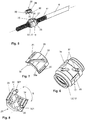
- Figur 2:
- eine räumliche Darstellung eines erfindungsgemäßen Kugelgewindetriebs ohne das umschließende Gehäuse,
- Figur 3:
- einen Längsschnitt durch den Kugelgewindetrieb,
- Figur 4:
- eine teilweise Explosionsdarstellung des Schrägkugellagers entsprechend den
Figuren 2 und3 , - Figur 5:
- eine teilweise Explosionsdarstellung des Kugelgewindetriebs mit Kugelrückführung entsprechend den
Figuren 2 und3 , - Figur 6:
- eine räumliche Ansicht der Kugelmutter,
- Figur 7:
- eine räumliche Darstellung der Kugelrückführung in Ansicht von oben,
- Figur 8:
- eine räumliche Darstellung der Kugelrückführung in Ansicht von unten,
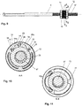
- Figur 9:
- eine seitliche Ansicht des Kugelgewindetriebes,
- Figur 10:
- einen Querschnitt durch den Kugelgewindetrieb entlang der Linie A-A, sowie
- Figur 11:
- einen Querschnitt durch den Kugelgewindetrieb entlang der Linie B-B.
- In der
Figur 1 ist eine elektromechanische Kraftfahrzeuglenkung 1 mit einem Lenkrad 2, das mit einer oberen Lenkwelle 3 und einer unteren Lenkwelle 4 drehfest gekoppelt ist, schematisch dargestellt. Die obere Lenkwelle 3 steht über einen Torsionsstab in funktioneller Verbindung mit der unteren Lenkwelle 4. Die untere Lenkwelle 4 ist mit einem Ritzel 5 drehfest verbunden. Das Ritzel 5 kämmt in bekannter Weise mit einem Zahnsegment 6' einer Zahnstange 6. Die Zahnstange 6 ist in einem Lenkungsgehäuse in Richtung ihrer Längsachse verschieblich gelagert. An ihrem freien Ende ist die Zahnstange 6 mit Spurstangen 7 über nicht dargestellte Kugelgelenke verbunden. Die Spurstangen 7 selbst sind in bekannter Weise über Achsschenkel mit je einem gelenkten Rad 8 des Kraftfahrzeugs verbunden. Eine Drehung des Lenkrades 2 führt über die Verbindung der Lenkwelle 3, 4 und des Ritzels 5 zu einer Längsverschiebung der Zahnstange 6 und damit zu einer Verschwenkung der gelenkten Räder 8. Die gelenkten Räder 8 erfahren über eine Fahrbahn 80 eine Rückwirkung, die der Lenkbewegung entgegen wirkt. Zum Verschwenken der Räder 8 ist folglich eine Kraft erforderlich, die ein entsprechendes Drehmoment am Lenkrad 2 erforderlich macht. Ein Elektromotor 9 einer Servoeinheit 10 ist vorgesehen, um den Fahrer bei dieser Lenkbewegung zu unterstützen. Dazu treibt der Elektromotor 9 über einen Riementrieb 11 eine Kugelmutter 13 eines Kugelgewindetriebs 12 an. Eine Drehung der Mutter versetzt die Gewindespindel des Kugelgewindetriebs 12, die Teil der Zahnstange 6 ist, in eine Axialbewegung, die letztlich eine Lenkbewegung für das Kraftfahrzeug bewirkt. - Auch wenn hier im Beispiel eine elektromechanische Servolenkung mit mechanischer Kopplung zwischen Lenkrad 2 und Lenkritzel 5 dargestellt ist, kann die Erfindung auch für Kraftfahrzeuglenkungen angewendet werden, bei denen keine mechanische Kopplung vorhanden ist. Derartige Lenksysteme sind unter dem Begriff Steer-by-Wire bekannt.
- In der
Figur 2 ist der Kugelgewindetrieb räumlich dargestellt. Eine Gewindespindel 6" ist Teil der Zahnstange 6 und beabstandet zu dem Zahnsegment 6' angeordnet. Die Kugelmutter 13 weist auf ihrer äußeren Umfangsfläche eine Riemenscheibe 14 auf. - In
Figur 3 sind die Kugelmutter 13 und die Gewindespindel 6" in einem Längsschnitt dargestellt. Die Kugelmutter 13 ist in einem zweireihigen Schrägkugellager 15 drehbar gelagert. Das Lager 15 weist einen einzigen gemeinsamen Innenring 16 auf, der durch die Kugelmutter 13 gebildet ist. Dazu weist die Kugelmutter 13 an ihren Enden 13' auf ihrer Außenumfangsfläche 16 jeweils eine umlaufende Ausnehmung 17 für eine Kugellaufbahn auf. Die Ausnehmung 17 bzw. das Laufbahnprofil ist dabei entsprechend einem Schrägkugellager ausgestaltet. Das Laufbahnprofil 17 und oder die Hülse des Schrägkugellagers kann als gotisches Profil ausgebildet sein, sodass ein Punktkontakt zwischen Laufbahn und Kugeln 100 entsteht Dadurch wird eine gleichmäßige Lastverteilung, eine hohe Steifigkeit sowie bessere Laufeigenschaften mit genauerer Führung ermöglicht. Bevorzugt haben die Kugeln einen Zweipunktkontakt zwischen der Ausnehmung 17 und der Hülse 19. Weiter bevorzugt kann zwischen den Enden 13' der Kugelmutter 13 und der Hülse ein Vierpunktkontakt vorliegen. Hierzu kann das Ende 13' der Kugelmutter als Trichterform ausgebildet sein. - Das Lager 15 weist weiterhin zwei separate Außenringe 18 auf. Die Außenringe 18 sind jeweils in einer separaten Hülse 19 aufgenommen, die in einem Lagersitz 20 des Gehäuses 21 angeordnet ist. Auf der Kugelmutter 13 ist die Riemenscheibe 14 des Zahnriemenantriebs 11 drehfest befestigt. Die Hülse 19 wird bevorzugt aus einem Werkstoff gebildet, der eine größere Wärmeausdehnung als Aluminium und Stahl besitzt. Insbesondere ist die Hülse 19 bevorzugt aus einem Kunststoff, besonders bevorzugt aus PA66GF30 (Polyamid 66 mit Glasfaserverstärkung mit 30% Volumenanteil) gebildet. Sie ist bevorzugt aus Kunststoff gefertigt und kompensiert Wärmeausdehnungen zwischen dem Getriebegehäuse 21 und dem Kugelmuttertrieb 12. Bevorzugt umfasst die Hülse eine kreiszylindrische Umfangswand 191, die das Lager 15 und die Lagerachse 24 umschließt, und einen kreiszylindrischen Bodenbereich 192, der sich radial nach Innen in Richtung der Lagerachse 24 erstreckt und eine kreiszylindrische Öffnung 193 aufweist, die die Lagerachse 24 umschließt. Die beiden separaten Hülsen 19 sind dabei bevorzugt derart angeordnet, dass die beiden Lager 15 zwischen den beiden Bodenbereiche 192 angeordnet sind. Bevorzugt sind die Bodenbereiche 192 eben ausgebildet mit bevorzugt konstanter Dicke. Es ist aber auch denkbar und möglich, die Bodenbereiche gezielt mit Rillen, Gravuren oder Rippen oder einer Wellenform zu versehen, um beispielsweise die Schmierung und/oder die Wärmeeigenschaften gezielt zu beeinflussen.
- Zur weiteren Verbesserung der Kompensationseigenschaften kann die Hülse in ihrer Umfangswand 191 Ausnehmungen, bevorzugt sich in Richtung der Lagerachse 24 erstreckende Schlitze 194 aufweisen. Diese Schlitze laufen bevorzugt zum bis ans offene Ende der Umfangswand 191, das vom Bodenbereich 192 weggerichtet ist. Mit anderen Worten sind die Schlitze 194 in Richtung der Riemenscheibe 14 geöffnet.
- Die Hülse 19 ist bevorzugt einstückig aus einem einzigen Bauteil, bevorzugt integral aus einem einzigen Werkstoff gebildet, besonders bevorzugt in einem Spritzgussverfahren.
- Wie in
Figur 4 dargestellt, ist in der Hülse 19 in der bevorzugten Ausführungsform eine Wellfeder 22 angeordnet, die das Lager 15 in Axialrichtung vorspannt. Die Wellfeder 22 liegt zwischen Hülse 19 und Lageraußenring 18. Durch die Kombination von Hülse 19 und Wellfeder 22 lässt sich die Anbindungssteifigkeit einstellen. Zudem ermöglicht diese Kombination eine Dämpfung der Bewegung des Lagers 15 bei dynamischen Belastungen. - Je nach Anwendungsfall kann jedoch diese Wellfeder 22 durch eine Tellerfeder oder durch eine Kombination aus Tellerfeder und Wellfeder ersetzt werden.
- Die Kugeln 100 des Schrägkugellagers 15 werden in einem Kugelkäfig 101 geführt.
- Die Laufbahnen des zweireihigen Schrägkugellagers 15 sind so ausgeführt, dass die Verbindungslinien 23, 23', 23", 23"' der Berührungspunkte zwischen Kugel und Laufbahnen die Lagerachse 24 zwischen den Außenringen 18 liegend schneiden. Zwischen den beiden Schnittpunkten mit der Lagerachse 24 bildet sich ein vordefinierter Stützabstand X aus. Durch den großen Stützabstand X wird das Lager 15 besonders kippsteif. Für eine besonders hohe Kippsteifigkeit liegt der Stützabstand X bevorzugt in einem Intervall zwischen dem einfachen und dem dreifachen Durchmesser der Kugeln 100 des Schräglagers. Besonders zu bevorzugen ist ein Stützabstand der dem doppelten Durchmesser der Kugeln 100 des Schrägkugellagers entspricht. Die Auflagefläche der Kugel 100 auf der Laufbahnfläche 17 und einer inneren Fläche der Hülse entspricht bevorzugt einer viertel Kugelumfangsfläche. Es bleibt bevorzugt sowohl auf der Laufbahnfläche als auch auf der inneren Fläche der Hülse ein Hinterschnitt, welcher nicht von der Kugel berührt wird. Als Kontaktwinkel α wird der Winkel bezeichnet, den eine Verbindungslinie der beiden Berührungspunkte zwischen Kugel 100 und Laufbahnen mit der Radialebene einschließt und unter dem die Belastung von einer Laufbahn auf die andere übertragen wird. Bevorzugt ist der Kontaktwinkel für beide Reihen des Lagers 15 gleich groß. Mit einem vordefinierten Wert des Stützabstandes X lässt sich bei einem bestimmten Kontaktwinkel α die optimale Kippsteifigkeit des Lagers 15 einstellen.
- In den
Figuren 5 bis 8 ist die Kugelmutter 13 und eine Kugelrückführung 25 im Detail dargestellt. Die Ausschnitte zeigen die Zahnstange 6 mit Kugelgewinde 6" und dem drauf angeordneten Kugelgewindetrieb ohne Riemenscheibe. - In der
Figur 4 ist die Kugelmutter 13 mit aufgesetztem Umlenkkörper 26 gezeigt. Die Kugelmutter 13 trägt auf ihrer Innenseite ein Kugelgewinde, in dem sich in an sich bekannter Weise Kugeln abwälzen. Die Kugelmutter 13 weist zwei durchsetzende Ausnehmungen 27 auf. Jeweils eine Ausnehmung 27 ist für den Eintritt bzw. Austritt von Kugeln 28 für die externe Kugelrückführung zu dem gegenüberliegenden Ende des Kugelgewindes vorgesehen. Die Kugelrückführung 25, die die beiden Ausnehmungen 27 miteinander verbindet, wird zumindest teilweise durch den Umlenkkörper 26 gebildet. Die Kugelrückführung 25 ist U-förmig ausgebildet. Der Rückführungskanal wird zumindest teilweise durch eine Ausnehmung 29 in dem Umlenkkörper 26 und zwei daran anschließende Zapfen 30 gebildet. Die Zapfen weisen jeweils einen Zapfeneinlauf 301 auf. Die Ausnehmung 29 ist diagonal über den Umlenkkörper 26 angeordnet, der als Aufsatz auf seiner Innenseite an die Krümmung der Oberseite der Kugelmutter 13 angepasst ist und sich in Umfangsrichtung über einen begrenzten Sektor der Kugelmutter 13 erstreckt. Wie inFigur 5 gezeigt, wird der Umlenkkörper 26 mittels der Zapfen 30 in die beiden Ausnehmungen 27 der Kugelmutter 13 eingesetzt, so dass die Kugelrückführung 25 mit beiden Enden des Kugelgewindes verbunden ist. - Mit Vorzug sind die Zapfen 30 in einem Winkel β ausgerichtet, so dass die Zapfen 30 unter Vorspannung in die Ausnehmungen 27 eingefügt werden, wobei die Vorspannung den Zapfeneinlauf 301 in die Ausnehmung 27 vorspannt. Dadurch ist der Übergang der Kugeln 28 in den Rückführungskanal 25' verbessert. Insbesondere können dadurch die Anforderungen an die Herstelltoleranzen für den Umlenkkörper gesenkt werden.
- Der Umlenkkörper kann auf der Oberseite und/oder auf der Unterseite mit wabenartigen Aussparungen oder Vertiefungen ausgebildet oder durchsetzt sein.
- In den
Figuren 6 bis 8 sind die Kugelmutter 13 und der aufgesetzte Umlenckörper 26 im Detail dargestellt. Neben den Zapfen 30 weist der Umlenkkörper 26 seitlich angeordnete Stege 31, 32, 33, 34 auf. Die Stege 31, 32, 33, 34 erstrecken sich in Längsrichtung 24 der Kugelmutter 13 und es sind jeweils auf der Oberseite zwei Stege 31, 32 und auf der Unterseite zwei Stege 33, 34 des Umlenkkörpers 26 angeordnet, die bevorzugt mit dem Umlenkkörper 26 einstückig ausgebildet sind. Die Stege der rechten Seite 31, 34 sind bevorzugt zu den Stegen der linken Seite 32, 33 in Längsrichtung 24 versetzt und bevorzugt punktsymmetrisch angeordnet. Bevorzugt ist der Umlenkkörper 26 aus Kunststoff gebildet, besonders bevorzugt aus PA66GF30 (Polyamid 66 mit Glasfaserverstärkung mit 30% Volumenanteil) gebildet. Die Stege der Unterseite 33, 34 greifen jeweils in dazu passende längliche Ausnehmung 35 in der Kugelmutter 13 ein. Diese Stege 33, 34 sind bevorzugt als Schnappelement ausgebildet und rasten in die Ausnehmung der Kugelmutter ein, wobei ein Formschluss durch elastische Verformung der Stege erreicht wird. Es kann vorgesehen sein, dass die Stege der Unterseite 33, 34 einen Winkel größer Null zueinander einnehmen, um dadurch eine bessere Vorspannung zu bilden. Die Stege auf der Oberseite 31, 32 greifen, wie in denFiguren 9 bis 11 dargestellt, in entsprechende Ausnehmungen 36 der Riemenscheibe 14 ein. Sie bilden eine Verdrehsicherung und eine Abstützung für die Riemenscheibe 14 mittels Formschluss. Eine Drehmomentübertragung von der Riemenscheibe auf die Kugelmutter erfolgt ausschließlich über die Stege 31, 32 und die korrespondierenden Ausnehmungen 36 in der Riemenscheibe 14, sowie der Bogenform in der Oberfläche 26a im Umlenkkörper 26 in Kontakt mit einer Ausbuchtung 14a der Riemenscheibe 14. Der Rückführungskanal 25' der Kugelrückführung 25 wird von dem Umlenkkörper 26 und der Innenseite der Riemenscheibe 14 und bevorzugt von der Ausbuchtung 14a gebildet. Die Ausnehmung 29 wird nach oben hin von der Riemenscheibe, insbesondere von deren Ausbuchtung 14a, abgedeckt, so dass sich ein geschlossener Rückführungskanal 25' ausbildet. Die Riemenscheibe weist dafür auf ihrer Innenseite ein entsprechendes Profil auf. Zwischen der Riemenscheibe 14 und der Kugelrückführung kann ein einteiliges aus einem einzigen Bauteil, bevorzugt integral aus einem einzigen Werkstoff gebildetes oder zweiteiliges Zwischenelement aus Kunststoff vorgesehen sein, welches am Außenumfang mit dem Profil auf der Innenseite der Riemenscheibe korrespondiert und dadurch axial gesichert ist. Der Rückführungskanal 25' wird durch die ballige Innenkontur des Zwischenelements aufgenommen und geschlossen. Dadurch können sich die Kugeln 28 entlang der U-förmigen Bahn bewegen und werden in dem Kanal gehalten. Mit dem Zwischenelement kann die Presspassung reduziert werden. Die Teilung des Rückführungskanals 25' zwischen dem Umlenkkörper 26 und der Hülse verläuft in der äußeren Berührebene der Kugeln 28. Bei der Montage wird als erstes der Umlenkkörper 26 auf die Kugelmutter 13 gesteckt und dann axial die Hülse auf die Kugelmutter 13 geschoben. Der Montageaufwand ist somit sehr gering. Durch die Verwendung der Riemenscheibe 14 als Teil des Rückführungskanals 25' wird die Anzahl der notwendigen Bauteile des Kugelgewindetriebs reduziert. Zudem ist die Oberfläche der Riemenscheibe mit der die Kugeln in dem Rückführungskanal in Kontakt kommen so hart und widerstandsfähig, dass der Verschleiß minimiert wird, was die Lebensdauer der Rückführung deutlich erhöht. - Durch die Anordnung der Stege kann der Zusammenbau der Riemenscheibe und der Kugelmutter mit spielfreiem Sitz ohne Presspassung erfolgen. Das hat den Vorteil, dass die Kugelmutter durch den Fügevorgang nicht nachteilig verformt wird.
- Das Lager 15 der Kugelmutter 13 ist so ausgestaltet, dass der Umlenkkörper 26 zwischen Kugelmutter und Riemenscheibe angeordnet werden kann. Die Kugelrückführung bzw. der Umlenkkörper findet somit Platz innerhalb des zweireihigen Lagers, wodurch die Anordnung besonders kompakt wird.
Claims (14)
- Elektromechanische Servolenkung (1) für ein Kraftfahrzeug, mit einem Servomotor (9), der ein axial verlagerbares Bauelement (6) über eine in einem Gehäuse (21) um eine Längsachse drehbar in einem Lager (15) gelagerte Kugelmutter (13) antreibt, wobei die Kugelmutter (13) mit einer an dem Bauelement (6) ausgebildeten Gewindespindel (6') in Eingriff steht und auf ihrer Innenseite ein Kugelgewinde zum Abwälzen von Kugeln (28) aufweist, und mit einer externen Kugelrückführung (25), die den Anfang des Kugelgewindes mit dem Ende des Kugelgewindes verbindet, um ein endloses Umlaufen der Kugeln (28) zu ermöglichen, und mit einem Umlenkkörper (26), wobei ein Rückführungskanal (25') der Kugelrückführung (25) durch den Umlenkkörper (26) und eine Riemenscheibe (14) gebildet ist, dadurch gekennzeichnet, dass der Umlenkkörper (26) auf seiner Außenseite wenigstens zwei Stege (31, 32) aufweist, die derart in die Riemenscheibe (14) eingreifen, dass ein Drehmoment von der Riemenscheibe (14) auf die Kugelmutter (13) übertragbar ist.
- Elektromechanische Servolenkung nach Anspruch 1, dadurch gekennzeichnet, dass der Umlenkkörper (26) auf seiner Innenseite wenigstens zwei Stege (33, 34) aufweist, die im Betrieb in korrespondierende Ausnehmungen (35) der Kugelmutter (13) greifen.
- Elektromechanische Servolenkung nach Anspruch 1 oder 2, dadurch gekennzeichnet, dass die Stege (31, 32, 33, 34) sich in Längsrichtung (24) erstrecken.
- Elektromechanische Servolenkung nach einem der vorhergehenden Ansprüche 1 bis 3, dadurch gekennzeichnet, dass die Stege der einen Seite (31, 34) und die Stege der anderen Seite (32, 33) zueinander in Längsrichtung versetzt angeordnet sind.
- Elektromechanische Servolenkung nach einem der vorhergehenden Ansprüche 1 bis 4, dadurch gekennzeichnet, dass die Stege der Unterseite (33, 34) Schnappelemente sind und mit der jeweiligen Ausnehmung (35) der Kugelmutter (13) eine Schnappverbindung eingehen.
- Elektromechanische Servolenkung nach einem der vorhergehenden Ansprüche 1 bis 5, dadurch gekennzeichnet, dass die Stege (31, 32, 33, 34) einstückig mit dem Umlenkkörper (26) ausgebildet sind.
- Elektromechanische Servolenkung nach einem der vorhergehenden Ansprüche, dadurch gekennzeichnet, dass der Umlenkkörper (26) Zapfen (30) zur Positionierung des Umlenkkörpers (26) auf der Kugelmutter (13) aufweist.
- Elektromechanische Servolenkung nach einem der vorhergehenden Ansprüche, dadurch gekennzeichnet, dass die Kugelmutter (13) zwei Ausnehmungen (27) für den Eintritt bzw. Austritt von Kugeln (28) für die externe Rückführung zu dem gegenüberliegenden Ende des Kugelgewindes aufweist.
- Elektromechanische Servolenkung nach Ansprüchen 7 und 8, dadurch gekennzeichnet, dass die Zapfen (30) des Umlenkkörpers (26) in die Ausnehmungen (27) der Kugelmutter (13) eingreifen.
- Elektromechanische Servolenkung nach einem der vorhergehenden Ansprüche, dadurch gekennzeichnet, dass das Lager (15) ein zweireihiges Schrägkugellager mit wenigstens einem Lagerinnenring (16) und zwei Lageraußenringen (18) ist, wobei die Riemenscheibe (14) und der Umlenkkörper (26) zwischen den Lageraußenringen (18) angeordnet ist.
- Elektromechanische Servolenkung nach Anspruch 10, dadurch gekennzeichnet, dass die Kontaktwinkel (α) des zweireihigen Schrägkugellagers (15) so ausgewählt sind, dass sich ein Stützabstand (X) ausbildet.
- Elektromechanische Servolenkung nach Anspruch 10 oder 11, dadurch gekennzeichnet, dass die zwei Lageraußenringe (18) in einer Hülse (19) aufgenommen sind, die in einem Lagersitz (20) des Gehäuses (21) angeordnet ist.
- Elektromechanische Servolenkung nach Anspruch 12, dadurch gekennzeichnet, dass die Hülse (19) derart ausgestaltet ist, Wärmeausdehnungen zwischen dem Getriebegehäuse (21) und der Kugelmutter (13) zu kompensieren.
- Elektromechanische Servolenkung nach einem der vorhergehenden Ansprüche, dadurch gekennzeichnet, dass das Bauelement (6) eine Zahnstange eines Zahnstangenlenkgetriebes ist.
Priority Applications (1)
| Application Number | Priority Date | Filing Date | Title |
|---|---|---|---|
| PL17731903T PL3475146T3 (pl) | 2016-06-22 | 2017-06-22 | Mechanizm śrubowo-toczny elektromechanicznego wspomagania układu kierowniczego z korpusami nawrotnymi do powrotnego prowadzenia kulek |
Applications Claiming Priority (2)
| Application Number | Priority Date | Filing Date | Title |
|---|---|---|---|
| DE102016007542.2A DE102016007542A1 (de) | 2016-06-22 | 2016-06-22 | Kugelgewindetrieb einer elektromechanischen Servolenkung mit Umlenkkörper für eine Kugelrückführung |
| PCT/EP2017/065358 WO2017220713A1 (de) | 2016-06-22 | 2017-06-22 | Kugelgewindetrieb einer elektromechanischen servolenkung mit umlenkkörper für eine kugelrückführung |
Publications (2)
| Publication Number | Publication Date |
|---|---|
| EP3475146A1 EP3475146A1 (de) | 2019-05-01 |
| EP3475146B1 true EP3475146B1 (de) | 2021-02-24 |
Family
ID=59093579
Family Applications (1)
| Application Number | Title | Priority Date | Filing Date |
|---|---|---|---|
| EP17731903.5A Active EP3475146B1 (de) | 2016-06-22 | 2017-06-22 | Kugelgewindetrieb einer elektromechanischen servolenkung mit umlenkkörper für eine kugelrückführung |
Country Status (7)
| Country | Link |
|---|---|
| US (1) | US10913484B2 (de) |
| EP (1) | EP3475146B1 (de) |
| CN (1) | CN109311505B (de) |
| DE (1) | DE102016007542A1 (de) |
| ES (1) | ES2866886T3 (de) |
| PL (1) | PL3475146T3 (de) |
| WO (1) | WO2017220713A1 (de) |
Families Citing this family (9)
| Publication number | Priority date | Publication date | Assignee | Title |
|---|---|---|---|---|
| US10322744B2 (en) | 2017-06-09 | 2019-06-18 | Steering Solutions Ip Holding Corporation | Road wheel actuator assembly |
| JP7132778B2 (ja) * | 2018-07-18 | 2022-09-07 | 日立Astemo株式会社 | ステアリング装置 |
| US11572936B2 (en) * | 2019-02-28 | 2023-02-07 | Hl Mando Corporation | Ball return tube for ball nut assembly |
| US11465673B2 (en) * | 2019-04-25 | 2022-10-11 | Schaeffler Technologies AG & Co. KG | Motor-assisted steering ball-screw |
| JP2021076178A (ja) * | 2019-11-07 | 2021-05-20 | 日本精工株式会社 | 動力伝達装置 |
| DE102020107119A1 (de) | 2020-03-16 | 2021-09-16 | Bayerische Motoren Werke Aktiengesellschaft | Lenksystem eines Fahrzeugs |
| CN115956171A (zh) * | 2020-08-24 | 2023-04-11 | 日本精工株式会社 | 滚珠丝杠装置的润滑脂封入方法及润滑脂封入装置、以及滚珠丝杠装置、滚珠丝杠装置的制造方法、直动致动器的制造方法、车辆用制动器的制造方法及车辆的制造方法 |
| DE102021200559A1 (de) | 2021-01-22 | 2022-07-28 | Thyssenkrupp Ag | Elektromechanische Servolenkung für ein Kraftfahrzeug |
| DE102022201147A1 (de) | 2022-02-03 | 2023-08-03 | Volkswagen Aktiengesellschaft | Kugelgewindetrieb, insbesondere für eine Kraftfahrzeuglenkung, und Kraftfahrzeuglenkung |
Family Cites Families (66)
| Publication number | Priority date | Publication date | Assignee | Title |
|---|---|---|---|---|
| DE1066059B (de) | 1956-07-19 | 1959-09-24 | ||
| DE2400902C2 (de) | 1974-01-09 | 1982-05-27 | A. Friedr. Flender Gmbh & Co Kg, 4290 Bocholt | Wälzlagereinbau |
| IT212198Z2 (it) | 1987-07-24 | 1989-07-04 | Roltra Spa | Attuatore assiale |
| US5809838A (en) * | 1995-05-30 | 1998-09-22 | Nsk Ltd. | Ball screw device with means for maintaining balance |
| US5975234A (en) | 1997-12-03 | 1999-11-02 | Trw Inc. | Electric steering system with plastic motor tube |
| JPH11198828A (ja) | 1998-01-20 | 1999-07-27 | Mitsuba Corp | 電気式動力操舵装置 |
| US6499369B1 (en) | 1999-09-16 | 2002-12-31 | Delphi Technologies, Inc. | Rack ball nut interface |
| JP3844943B2 (ja) * | 2000-04-03 | 2006-11-15 | Ntn株式会社 | ボールねじおよびそれを具備する電動パワーステアリング装置 |
| NL1015601C2 (nl) | 2000-07-04 | 2002-01-08 | Skf Eng & Res Centre Bv | Lagereenheid met ge´ntegreerde moer, en actuator met een dergelijke eenheid. |
| US6406188B1 (en) | 2000-09-15 | 2002-06-18 | Hiwin Technologies Corp. | Ball bushed bearing screw bolt and nut |
| US6883635B2 (en) | 2001-06-29 | 2005-04-26 | Delphi Technologies, Inc. | Ball-screw assembly isolator |
| JP4786835B2 (ja) * | 2001-09-05 | 2011-10-05 | 株式会社ジェイテクト | ボールねじ装置 |
| JP3993504B2 (ja) * | 2001-12-05 | 2007-10-17 | Thk株式会社 | ボールねじの循環部品及びボールねじ |
| US20030172759A1 (en) * | 2002-02-25 | 2003-09-18 | Nsk Ltd. | Ball screw |
| JP2004009882A (ja) | 2002-06-06 | 2004-01-15 | Nsk Ltd | 電動パワーステアリング装置 |
| JP4053826B2 (ja) * | 2002-06-25 | 2008-02-27 | Thk株式会社 | 循環部品、並びにこの循環部品を用いた運動案内装置及びボールねじ |
| CN1688472A (zh) * | 2002-08-22 | 2005-10-26 | 日本精工株式会社 | 电动助力转向装置 |
| DE10258826A1 (de) | 2002-12-17 | 2004-07-15 | Ina-Schaeffler Kg | Antriebseinrichtung mit einem Wälzkörpergewindetrieb |
| JP4089781B2 (ja) | 2003-04-15 | 2008-05-28 | 株式会社ジェイテクト | 電動パワーステアリング装置 |
| DE102004023354A1 (de) | 2004-05-12 | 2005-12-08 | Ina-Schaeffler Kg | Kugelgewindetrieb |
| US20090294203A1 (en) | 2004-08-06 | 2009-12-03 | Nsk Ltd. | electric power steering apparatus |
| CN101001778A (zh) | 2004-08-06 | 2007-07-18 | 日本精工株式会社 | 电动转向装置 |
| DE102004055423A1 (de) | 2004-11-17 | 2006-05-24 | Schaeffler Kg | Kugelgewindetrieb |
| KR100674532B1 (ko) | 2005-02-28 | 2007-01-29 | 한국과학기술연구원 | 고분자 위에 접착력이 강한 금속 박막을 형성하기 위한 방법 및 장치 |
| TWI274214B (en) | 2005-04-19 | 2007-02-21 | Young Lighting Technology Inc | Multi-chip light emitting diode illumination apparatus |
| CN2849305Y (zh) | 2005-11-10 | 2006-12-20 | 北汽福田汽车股份有限公司 | 一种转向管柱轴承安装定位装置 |
| CN201021709Y (zh) | 2006-11-29 | 2008-02-13 | 李敬宇 | 滚珠螺母装置和滚动螺旋传动装置 |
| DE102007048075B4 (de) | 2007-10-05 | 2016-03-31 | Thyssenkrupp Presta Aktiengesellschaft | Elektrische Servolenkung aufweisend einen Kugelgewindetrieb mit angefedertem Lager |
| DE102007049114B4 (de) * | 2007-10-12 | 2018-02-15 | Volkswagen Ag | Zahnriemenrad einer elektromechanischen Lenkung mit Kugelgewindemutter |
| US8205515B2 (en) | 2008-04-24 | 2012-06-26 | Ford Global Technologies | Rack bushing for an automotive steering system |
| US8955404B2 (en) * | 2008-08-29 | 2015-02-17 | Hiwin Technologies Corp | Ball screw module |
| US8479605B2 (en) | 2008-09-19 | 2013-07-09 | James J. Shavrnoch | Rotary-to-linear mechanism having an isolator |
| DE102008063712A1 (de) | 2008-12-19 | 2010-06-24 | Thyssenkrupp Presta Ag | Lenksystem mit geräuschdämmenden Komponenten aus Verbundwerkstoff |
| WO2010085346A1 (en) | 2009-01-23 | 2010-07-29 | Skf Usa Inc. | Bearing assembly for a power steering mechanism |
| DE102009009522A1 (de) | 2009-02-18 | 2010-08-19 | Schaeffler Technologies Gmbh & Co. Kg | Umlenkkörper für einen Kugelgewindetrieb |
| DE102009016199B4 (de) * | 2009-04-03 | 2019-05-09 | Schaeffler Technologies AG & Co. KG | Kugelmutter und Kugelgewindetrieb |
| CN102042465A (zh) * | 2009-10-22 | 2011-05-04 | 鸿富锦精密工业(深圳)有限公司 | 电子设备及其旋转装置 |
| DE102009050802A1 (de) | 2009-10-27 | 2011-04-28 | Volkswagen Ag | Kugelgewindemutter |
| DE102009052822A1 (de) | 2009-11-13 | 2011-05-19 | Thyssenkrupp Presta Ag | Elektromechanische Servolenkung mit Korrosionsschutz |
| DE102010025589A1 (de) | 2010-06-29 | 2011-12-29 | Schaeffler Technologies Gmbh & Co. Kg | Kugelgewindetrieb |
| DE102010050175A1 (de) | 2010-10-30 | 2012-05-03 | Volkswagen Ag | Kugelgewindemutter |
| DE102010054828A1 (de) | 2010-12-16 | 2012-06-21 | Thyssenkrupp Presta Ag | Servolenkung mit Spindeltrieb |
| DE102011082514A1 (de) | 2011-09-12 | 2013-03-14 | Schaeffler Technologies AG & Co. KG | Kugelgewindetrieb |
| JP2013103696A (ja) | 2011-11-16 | 2013-05-30 | Jtekt Corp | 電動パワーステアリング装置 |
| JP5953836B2 (ja) | 2012-03-09 | 2016-07-20 | 株式会社ジェイテクト | 電動パワーステアリング装置 |
| US9637164B2 (en) * | 2012-09-28 | 2017-05-02 | Steering Solutions Ip Holding Corporation | Nylon resin driven pulley |
| DE102012019227B4 (de) | 2012-10-01 | 2019-01-10 | Thyssenkrupp Presta Aktiengesellschaft | Kugelgewindetrieb und Servolenkung mit einem Kugelgewindetrieb |
| DE102013003749A1 (de) | 2013-03-06 | 2014-09-11 | Thyssenkrupp Presta Aktiengesellschaft | Winkelbewegliche Lageranordnung für Ritzel in Reduktionsgetrieben elektromechanischer Lenksysteme |
| DE102013006432A1 (de) | 2013-04-15 | 2014-10-16 | Thyssenkrupp Presta Aktiengesellschaft | Doppelwellfeder mit dämpfender Zwischenschicht |
| DE102013006992A1 (de) | 2013-04-16 | 2014-10-16 | Cw Bearing Gmbh | Kugelgewindemutter mit integrierten zweireihigen Kugellager |
| JP6131143B2 (ja) | 2013-08-02 | 2017-05-17 | 株式会社ショーワ | パワーステアリング装置 |
| JP2015047997A (ja) | 2013-09-03 | 2015-03-16 | 日立オートモティブシステムズステアリング株式会社 | パワーステアリング装置およびパワーステアリング装置の製造方法 |
| US9550518B2 (en) | 2013-12-31 | 2017-01-24 | Trw Automotive U.S. Llc | Electric power steering assembly |
| CN203793407U (zh) | 2014-01-28 | 2014-08-27 | 株式会社捷太格特 | 旋转装置 |
| KR102126228B1 (ko) | 2014-02-06 | 2020-06-25 | 주식회사 만도 | 전동기 및 이를 포함하는 전동식 동력 보조 조향장치 |
| CN203770410U (zh) | 2014-03-09 | 2014-08-13 | 宁波慈兴轴承有限公司 | 双外圈角接触滚珠丝母轴承组件 |
| JP6471411B2 (ja) | 2014-03-26 | 2019-02-20 | 株式会社ジェイテクト | ステアリング装置 |
| DE102014207922A1 (de) | 2014-04-28 | 2015-10-29 | Aktiebolaget Skf | Lagerring mit einem Temperaturkompensationsring, Lager mit dem Lagerring sowie Verfahren zum Herstellen eines Lagerrings |
| US20150336605A1 (en) | 2014-05-23 | 2015-11-26 | Steering Solutions Ip Holding Corporation | Steering system with tilted motor axis |
| DE102014221135B3 (de) | 2014-10-17 | 2016-01-07 | Schaeffler Technologies AG & Co. KG | Kugelgewindemutter |
| EP3227165B1 (de) | 2014-12-03 | 2021-02-17 | TRW Automotive U.S. LLC | Zahnstangenkugelmutteranordnung für ein fahrzeuglenkgetriebe und zugehörige komponenten dafür |
| DE102014225029A1 (de) | 2014-12-05 | 2016-06-09 | Aktiebolaget Skf | Temperaturkompensationsring, Lagerring sowie Lageranordnung |
| JP6374782B2 (ja) | 2014-12-12 | 2018-08-15 | 株式会社ショーワ | 車両用転舵装置 |
| CN204452566U (zh) | 2014-12-31 | 2015-07-08 | 天合汽车零部件(上海)有限公司 | 汽车电动助力转向系统的集成轴承式滚珠丝杠螺母结构 |
| FR3041830B1 (fr) | 2015-09-24 | 2019-04-26 | Aktiebolaget Skf | Verin electromecanique |
| KR101783100B1 (ko) | 2015-10-05 | 2017-09-28 | 주식회사 만도 | 랙구동형 동력 보조 조향장치 |
-
2016
- 2016-06-22 DE DE102016007542.2A patent/DE102016007542A1/de not_active Withdrawn
-
2017
- 2017-06-22 CN CN201780038057.2A patent/CN109311505B/zh active Active
- 2017-06-22 WO PCT/EP2017/065358 patent/WO2017220713A1/de unknown
- 2017-06-22 ES ES17731903T patent/ES2866886T3/es active Active
- 2017-06-22 EP EP17731903.5A patent/EP3475146B1/de active Active
- 2017-06-22 US US16/309,398 patent/US10913484B2/en active Active
- 2017-06-22 PL PL17731903T patent/PL3475146T3/pl unknown
Non-Patent Citations (1)
| Title |
|---|
| None * |
Also Published As
| Publication number | Publication date |
|---|---|
| DE102016007542A1 (de) | 2017-12-28 |
| US10913484B2 (en) | 2021-02-09 |
| CN109311505A (zh) | 2019-02-05 |
| WO2017220713A1 (de) | 2017-12-28 |
| US20190329815A1 (en) | 2019-10-31 |
| EP3475146A1 (de) | 2019-05-01 |
| PL3475146T3 (pl) | 2021-09-13 |
| ES2866886T3 (es) | 2021-10-20 |
| CN109311505B (zh) | 2021-07-06 |
Similar Documents
| Publication | Publication Date | Title |
|---|---|---|
| EP3475146B1 (de) | Kugelgewindetrieb einer elektromechanischen servolenkung mit umlenkkörper für eine kugelrückführung | |
| EP3475148B1 (de) | Kugelgewindetrieb einer elektromechanischen servolenkung mit integriertem schrägkugellager und kompensation unterschiedlicher wärmeausdehnungen | |
| EP2994362B1 (de) | Anfederungs-exzenterschwinge in ceps-anwendung | |
| DE102016211694B3 (de) | Getriebeeinheit für ein Kraftfahrzeug | |
| EP1774201B1 (de) | Kugelschraugetriebe für ein elektromechanisches lenksystem und mutter für ein kugelschraubgetriebe | |
| EP3573874B1 (de) | Motorisch verstellbare lenksäule für ein kraftfahrzeug und verstellantrieb für eine lenksäule | |
| EP2233381B1 (de) | Kostengünstiges Zahnstangenlenkgetriebe | |
| WO2017220715A1 (de) | Kugelgewindetrieb einer elektromechanischen servolenkung mit integriertem schrägkugellager | |
| DE102012019227B4 (de) | Kugelgewindetrieb und Servolenkung mit einem Kugelgewindetrieb | |
| EP1103411B2 (de) | Verstellvorrichtung für einen Fahrzeugsitz mit einer Spindel und einer zugeordneten Spindelmutter | |
| DE102017106671B4 (de) | Lenkgetriebe für Einzelradlenkung eines Kraftfahrzeugs mit Steer-by-Wire Lenksystem | |
| WO2018068932A1 (de) | Lenksystem | |
| DE19933875B4 (de) | Linearwälzlager zum Übertragen von Drehmomenten | |
| DE102008002176A1 (de) | Aktuator | |
| DE102016119367A1 (de) | Lenksystem | |
| DE112008004020T5 (de) | Kugelrückführungsmittel und Betätigungsvorrichtung, die ein derartiges Mittel umfasst | |
| DE202016103794U1 (de) | Getriebeeinheit für ein Kraftfahrzeug | |
| WO2019015710A1 (de) | Gewindemutter für einen kugelgewindetrieb | |
| EP3500766B1 (de) | Wälzlager für die lagerung einer antriebsschnecke einer elektromechanischen hilfskraftlenkung eines kraftfahrzeugs | |
| WO2017067921A1 (de) | Kugelrückführung mit axial montierbarer befestigungshülse | |
| DE102017219309B4 (de) | Aktuator einer Lenkung mit einem Spindelantrieb sowie Verfahren zur Montage eines Spindelantriebs | |
| EP3691957B1 (de) | Elektromechanische servolenkung mit schraubradgetriebe und einer kompensationseinrichtung zur abstützung eines loslagers am getriebegehäuse | |
| EP4179222B1 (de) | Hilfskraftlenkung für ein kraftfahrzeug | |
| DE102017115573A1 (de) | Wälzlager mit Toleranzring für ein Servolenksystem | |
| DE102016109847A1 (de) | Lenksystem, Lageranordnung und Lagerring |
Legal Events
| Date | Code | Title | Description |
|---|---|---|---|
| STAA | Information on the status of an ep patent application or granted ep patent |
Free format text: STATUS: UNKNOWN |
|
| STAA | Information on the status of an ep patent application or granted ep patent |
Free format text: STATUS: THE INTERNATIONAL PUBLICATION HAS BEEN MADE |
|
| PUAI | Public reference made under article 153(3) epc to a published international application that has entered the european phase |
Free format text: ORIGINAL CODE: 0009012 |
|
| STAA | Information on the status of an ep patent application or granted ep patent |
Free format text: STATUS: REQUEST FOR EXAMINATION WAS MADE |
|
| 17P | Request for examination filed |
Effective date: 20190122 |
|
| AK | Designated contracting states |
Kind code of ref document: A1 Designated state(s): AL AT BE BG CH CY CZ DE DK EE ES FI FR GB GR HR HU IE IS IT LI LT LU LV MC MK MT NL NO PL PT RO RS SE SI SK SM TR |
|
| AX | Request for extension of the european patent |
Extension state: BA ME |
|
| DAV | Request for validation of the european patent (deleted) | ||
| DAX | Request for extension of the european patent (deleted) | ||
| RAP1 | Party data changed (applicant data changed or rights of an application transferred) |
Owner name: THYSSENKRUPP PRESTA AG Owner name: THYSSENKRUPP AG |
|
| GRAP | Despatch of communication of intention to grant a patent |
Free format text: ORIGINAL CODE: EPIDOSNIGR1 |
|
| STAA | Information on the status of an ep patent application or granted ep patent |
Free format text: STATUS: GRANT OF PATENT IS INTENDED |
|
| INTG | Intention to grant announced |
Effective date: 20201105 |
|
| GRAS | Grant fee paid |
Free format text: ORIGINAL CODE: EPIDOSNIGR3 |
|
| GRAA | (expected) grant |
Free format text: ORIGINAL CODE: 0009210 |
|
| STAA | Information on the status of an ep patent application or granted ep patent |
Free format text: STATUS: THE PATENT HAS BEEN GRANTED |
|
| AK | Designated contracting states |
Kind code of ref document: B1 Designated state(s): AL AT BE BG CH CY CZ DE DK EE ES FI FR GB GR HR HU IE IS IT LI LT LU LV MC MK MT NL NO PL PT RO RS SE SI SK SM TR |
|
| REG | Reference to a national code |
Ref country code: CH Ref legal event code: EP |
|
| REG | Reference to a national code |
Ref country code: AT Ref legal event code: REF Ref document number: 1364095 Country of ref document: AT Kind code of ref document: T Effective date: 20210315 |
|
| REG | Reference to a national code |
Ref country code: IE Ref legal event code: FG4D Free format text: LANGUAGE OF EP DOCUMENT: GERMAN |
|
| REG | Reference to a national code |
Ref country code: DE Ref legal event code: R096 Ref document number: 502017009479 Country of ref document: DE |
|
| REG | Reference to a national code |
Ref country code: LT Ref legal event code: MG9D |
|
| REG | Reference to a national code |
Ref country code: NL Ref legal event code: MP Effective date: 20210224 |
|
| PG25 | Lapsed in a contracting state [announced via postgrant information from national office to epo] |
Ref country code: LT Free format text: LAPSE BECAUSE OF FAILURE TO SUBMIT A TRANSLATION OF THE DESCRIPTION OR TO PAY THE FEE WITHIN THE PRESCRIBED TIME-LIMIT Effective date: 20210224 Ref country code: BG Free format text: LAPSE BECAUSE OF FAILURE TO SUBMIT A TRANSLATION OF THE DESCRIPTION OR TO PAY THE FEE WITHIN THE PRESCRIBED TIME-LIMIT Effective date: 20210524 Ref country code: HR Free format text: LAPSE BECAUSE OF FAILURE TO SUBMIT A TRANSLATION OF THE DESCRIPTION OR TO PAY THE FEE WITHIN THE PRESCRIBED TIME-LIMIT Effective date: 20210224 Ref country code: FI Free format text: LAPSE BECAUSE OF FAILURE TO SUBMIT A TRANSLATION OF THE DESCRIPTION OR TO PAY THE FEE WITHIN THE PRESCRIBED TIME-LIMIT Effective date: 20210224 Ref country code: GR Free format text: LAPSE BECAUSE OF FAILURE TO SUBMIT A TRANSLATION OF THE DESCRIPTION OR TO PAY THE FEE WITHIN THE PRESCRIBED TIME-LIMIT Effective date: 20210525 Ref country code: NO Free format text: LAPSE BECAUSE OF FAILURE TO SUBMIT A TRANSLATION OF THE DESCRIPTION OR TO PAY THE FEE WITHIN THE PRESCRIBED TIME-LIMIT Effective date: 20210524 Ref country code: PT Free format text: LAPSE BECAUSE OF FAILURE TO SUBMIT A TRANSLATION OF THE DESCRIPTION OR TO PAY THE FEE WITHIN THE PRESCRIBED TIME-LIMIT Effective date: 20210624 |
|
| PG25 | Lapsed in a contracting state [announced via postgrant information from national office to epo] |
Ref country code: SE Free format text: LAPSE BECAUSE OF FAILURE TO SUBMIT A TRANSLATION OF THE DESCRIPTION OR TO PAY THE FEE WITHIN THE PRESCRIBED TIME-LIMIT Effective date: 20210224 Ref country code: LV Free format text: LAPSE BECAUSE OF FAILURE TO SUBMIT A TRANSLATION OF THE DESCRIPTION OR TO PAY THE FEE WITHIN THE PRESCRIBED TIME-LIMIT Effective date: 20210224 Ref country code: NL Free format text: LAPSE BECAUSE OF FAILURE TO SUBMIT A TRANSLATION OF THE DESCRIPTION OR TO PAY THE FEE WITHIN THE PRESCRIBED TIME-LIMIT Effective date: 20210224 Ref country code: RS Free format text: LAPSE BECAUSE OF FAILURE TO SUBMIT A TRANSLATION OF THE DESCRIPTION OR TO PAY THE FEE WITHIN THE PRESCRIBED TIME-LIMIT Effective date: 20210224 |
|
| PG25 | Lapsed in a contracting state [announced via postgrant information from national office to epo] |
Ref country code: IS Free format text: LAPSE BECAUSE OF FAILURE TO SUBMIT A TRANSLATION OF THE DESCRIPTION OR TO PAY THE FEE WITHIN THE PRESCRIBED TIME-LIMIT Effective date: 20210624 |
|
| REG | Reference to a national code |
Ref country code: ES Ref legal event code: FG2A Ref document number: 2866886 Country of ref document: ES Kind code of ref document: T3 Effective date: 20211020 |
|
| PG25 | Lapsed in a contracting state [announced via postgrant information from national office to epo] |
Ref country code: EE Free format text: LAPSE BECAUSE OF FAILURE TO SUBMIT A TRANSLATION OF THE DESCRIPTION OR TO PAY THE FEE WITHIN THE PRESCRIBED TIME-LIMIT Effective date: 20210224 Ref country code: SM Free format text: LAPSE BECAUSE OF FAILURE TO SUBMIT A TRANSLATION OF THE DESCRIPTION OR TO PAY THE FEE WITHIN THE PRESCRIBED TIME-LIMIT Effective date: 20210224 |
|
| REG | Reference to a national code |
Ref country code: DE Ref legal event code: R097 Ref document number: 502017009479 Country of ref document: DE |
|
| PG25 | Lapsed in a contracting state [announced via postgrant information from national office to epo] |
Ref country code: RO Free format text: LAPSE BECAUSE OF FAILURE TO SUBMIT A TRANSLATION OF THE DESCRIPTION OR TO PAY THE FEE WITHIN THE PRESCRIBED TIME-LIMIT Effective date: 20210224 Ref country code: DK Free format text: LAPSE BECAUSE OF FAILURE TO SUBMIT A TRANSLATION OF THE DESCRIPTION OR TO PAY THE FEE WITHIN THE PRESCRIBED TIME-LIMIT Effective date: 20210224 Ref country code: SK Free format text: LAPSE BECAUSE OF FAILURE TO SUBMIT A TRANSLATION OF THE DESCRIPTION OR TO PAY THE FEE WITHIN THE PRESCRIBED TIME-LIMIT Effective date: 20210224 |
|
| PLBE | No opposition filed within time limit |
Free format text: ORIGINAL CODE: 0009261 |
|
| STAA | Information on the status of an ep patent application or granted ep patent |
Free format text: STATUS: NO OPPOSITION FILED WITHIN TIME LIMIT |
|
| PG25 | Lapsed in a contracting state [announced via postgrant information from national office to epo] |
Ref country code: AL Free format text: LAPSE BECAUSE OF FAILURE TO SUBMIT A TRANSLATION OF THE DESCRIPTION OR TO PAY THE FEE WITHIN THE PRESCRIBED TIME-LIMIT Effective date: 20210224 Ref country code: MC Free format text: LAPSE BECAUSE OF FAILURE TO SUBMIT A TRANSLATION OF THE DESCRIPTION OR TO PAY THE FEE WITHIN THE PRESCRIBED TIME-LIMIT Effective date: 20210224 |
|
| REG | Reference to a national code |
Ref country code: CH Ref legal event code: PL |
|
| 26N | No opposition filed |
Effective date: 20211125 |
|
| PG25 | Lapsed in a contracting state [announced via postgrant information from national office to epo] |
Ref country code: SI Free format text: LAPSE BECAUSE OF FAILURE TO SUBMIT A TRANSLATION OF THE DESCRIPTION OR TO PAY THE FEE WITHIN THE PRESCRIBED TIME-LIMIT Effective date: 20210224 |
|
| REG | Reference to a national code |
Ref country code: BE Ref legal event code: MM Effective date: 20210630 |
|
| PG25 | Lapsed in a contracting state [announced via postgrant information from national office to epo] |
Ref country code: LU Free format text: LAPSE BECAUSE OF NON-PAYMENT OF DUE FEES Effective date: 20210622 |
|
| PG25 | Lapsed in a contracting state [announced via postgrant information from national office to epo] |
Ref country code: LI Free format text: LAPSE BECAUSE OF NON-PAYMENT OF DUE FEES Effective date: 20210630 Ref country code: IE Free format text: LAPSE BECAUSE OF NON-PAYMENT OF DUE FEES Effective date: 20210622 Ref country code: CH Free format text: LAPSE BECAUSE OF NON-PAYMENT OF DUE FEES Effective date: 20210630 |
|
| PG25 | Lapsed in a contracting state [announced via postgrant information from national office to epo] |
Ref country code: IS Free format text: LAPSE BECAUSE OF FAILURE TO SUBMIT A TRANSLATION OF THE DESCRIPTION OR TO PAY THE FEE WITHIN THE PRESCRIBED TIME-LIMIT Effective date: 20210624 |
|
| PG25 | Lapsed in a contracting state [announced via postgrant information from national office to epo] |
Ref country code: BE Free format text: LAPSE BECAUSE OF NON-PAYMENT OF DUE FEES Effective date: 20210630 |
|
| REG | Reference to a national code |
Ref country code: DE Ref legal event code: R084 Ref document number: 502017009479 Country of ref document: DE |
|
| PG25 | Lapsed in a contracting state [announced via postgrant information from national office to epo] |
Ref country code: CY Free format text: LAPSE BECAUSE OF FAILURE TO SUBMIT A TRANSLATION OF THE DESCRIPTION OR TO PAY THE FEE WITHIN THE PRESCRIBED TIME-LIMIT Effective date: 20210224 |
|
| PG25 | Lapsed in a contracting state [announced via postgrant information from national office to epo] |
Ref country code: HU Free format text: LAPSE BECAUSE OF FAILURE TO SUBMIT A TRANSLATION OF THE DESCRIPTION OR TO PAY THE FEE WITHIN THE PRESCRIBED TIME-LIMIT; INVALID AB INITIO Effective date: 20170622 |
|
| PGFP | Annual fee paid to national office [announced via postgrant information from national office to epo] |
Ref country code: FR Payment date: 20230628 Year of fee payment: 7 Ref country code: DE Payment date: 20230620 Year of fee payment: 7 Ref country code: CZ Payment date: 20230612 Year of fee payment: 7 |
|
| REG | Reference to a national code |
Ref country code: AT Ref legal event code: MM01 Ref document number: 1364095 Country of ref document: AT Kind code of ref document: T Effective date: 20220622 |
|
| PGFP | Annual fee paid to national office [announced via postgrant information from national office to epo] |
Ref country code: PL Payment date: 20230612 Year of fee payment: 7 |
|
| PG25 | Lapsed in a contracting state [announced via postgrant information from national office to epo] |
Ref country code: AT Free format text: LAPSE BECAUSE OF NON-PAYMENT OF DUE FEES Effective date: 20220622 |
|
| PGFP | Annual fee paid to national office [announced via postgrant information from national office to epo] |
Ref country code: IT Payment date: 20230623 Year of fee payment: 7 Ref country code: GB Payment date: 20230622 Year of fee payment: 7 Ref country code: ES Payment date: 20230830 Year of fee payment: 7 |