EP3434501A1 - Türinnenverkleidung und verfahren zur herstellung einer türinnenverkleidung - Google Patents
Türinnenverkleidung und verfahren zur herstellung einer türinnenverkleidung Download PDFInfo
- Publication number
- EP3434501A1 EP3434501A1 EP17770121.6A EP17770121A EP3434501A1 EP 3434501 A1 EP3434501 A1 EP 3434501A1 EP 17770121 A EP17770121 A EP 17770121A EP 3434501 A1 EP3434501 A1 EP 3434501A1
- Authority
- EP
- European Patent Office
- Prior art keywords
- inner panel
- door inner
- sheet portion
- top sheet
- standing wall
- Prior art date
- Legal status (The legal status is an assumption and is not a legal conclusion. Google has not performed a legal analysis and makes no representation as to the accuracy of the status listed.)
- Pending
Links
Images


Classifications
-
- B—PERFORMING OPERATIONS; TRANSPORTING
- B60—VEHICLES IN GENERAL
- B60J—WINDOWS, WINDSCREENS, NON-FIXED ROOFS, DOORS, OR SIMILAR DEVICES FOR VEHICLES; REMOVABLE EXTERNAL PROTECTIVE COVERINGS SPECIALLY ADAPTED FOR VEHICLES
- B60J5/00—Doors
- B60J5/04—Doors arranged at the vehicle sides
- B60J5/0411—Beltline
-
- B—PERFORMING OPERATIONS; TRANSPORTING
- B21—MECHANICAL METAL-WORKING WITHOUT ESSENTIALLY REMOVING MATERIAL; PUNCHING METAL
- B21D—WORKING OR PROCESSING OF SHEET METAL OR METAL TUBES, RODS OR PROFILES WITHOUT ESSENTIALLY REMOVING MATERIAL; PUNCHING METAL
- B21D22/00—Shaping without cutting, by stamping, spinning, or deep-drawing
- B21D22/20—Deep-drawing
- B21D22/208—Deep-drawing by heating the blank or deep-drawing associated with heat treatment
-
- B—PERFORMING OPERATIONS; TRANSPORTING
- B21—MECHANICAL METAL-WORKING WITHOUT ESSENTIALLY REMOVING MATERIAL; PUNCHING METAL
- B21D—WORKING OR PROCESSING OF SHEET METAL OR METAL TUBES, RODS OR PROFILES WITHOUT ESSENTIALLY REMOVING MATERIAL; PUNCHING METAL
- B21D22/00—Shaping without cutting, by stamping, spinning, or deep-drawing
- B21D22/20—Deep-drawing
- B21D22/22—Deep-drawing with devices for holding the edge of the blanks
-
- B—PERFORMING OPERATIONS; TRANSPORTING
- B21—MECHANICAL METAL-WORKING WITHOUT ESSENTIALLY REMOVING MATERIAL; PUNCHING METAL
- B21D—WORKING OR PROCESSING OF SHEET METAL OR METAL TUBES, RODS OR PROFILES WITHOUT ESSENTIALLY REMOVING MATERIAL; PUNCHING METAL
- B21D22/00—Shaping without cutting, by stamping, spinning, or deep-drawing
- B21D22/20—Deep-drawing
- B21D22/26—Deep-drawing for making peculiarly, e.g. irregularly, shaped articles
-
- B—PERFORMING OPERATIONS; TRANSPORTING
- B21—MECHANICAL METAL-WORKING WITHOUT ESSENTIALLY REMOVING MATERIAL; PUNCHING METAL
- B21D—WORKING OR PROCESSING OF SHEET METAL OR METAL TUBES, RODS OR PROFILES WITHOUT ESSENTIALLY REMOVING MATERIAL; PUNCHING METAL
- B21D24/00—Special deep-drawing arrangements in, or in connection with, presses
-
- B—PERFORMING OPERATIONS; TRANSPORTING
- B21—MECHANICAL METAL-WORKING WITHOUT ESSENTIALLY REMOVING MATERIAL; PUNCHING METAL
- B21D—WORKING OR PROCESSING OF SHEET METAL OR METAL TUBES, RODS OR PROFILES WITHOUT ESSENTIALLY REMOVING MATERIAL; PUNCHING METAL
- B21D53/00—Making other particular articles
- B21D53/88—Making other particular articles other parts for vehicles, e.g. cowlings, mudguards
-
- B—PERFORMING OPERATIONS; TRANSPORTING
- B60—VEHICLES IN GENERAL
- B60J—WINDOWS, WINDSCREENS, NON-FIXED ROOFS, DOORS, OR SIMILAR DEVICES FOR VEHICLES; REMOVABLE EXTERNAL PROTECTIVE COVERINGS SPECIALLY ADAPTED FOR VEHICLES
- B60J5/00—Doors
-
- B—PERFORMING OPERATIONS; TRANSPORTING
- B60—VEHICLES IN GENERAL
- B60J—WINDOWS, WINDSCREENS, NON-FIXED ROOFS, DOORS, OR SIMILAR DEVICES FOR VEHICLES; REMOVABLE EXTERNAL PROTECTIVE COVERINGS SPECIALLY ADAPTED FOR VEHICLES
- B60J5/00—Doors
- B60J5/04—Doors arranged at the vehicle sides
- B60J5/0412—Lower door structure
- B60J5/0413—Inner panel, e.g. characterised by carrying components
-
- B—PERFORMING OPERATIONS; TRANSPORTING
- B60—VEHICLES IN GENERAL
- B60J—WINDOWS, WINDSCREENS, NON-FIXED ROOFS, DOORS, OR SIMILAR DEVICES FOR VEHICLES; REMOVABLE EXTERNAL PROTECTIVE COVERINGS SPECIALLY ADAPTED FOR VEHICLES
- B60J5/00—Doors
- B60J5/04—Doors arranged at the vehicle sides
- B60J5/042—Reinforcement elements
- B60J5/0422—Elongated type elements, e.g. beams, cables, belts or wires
- B60J5/0423—Elongated type elements, e.g. beams, cables, belts or wires characterised by position in the lower door structure
- B60J5/0426—Elongated type elements, e.g. beams, cables, belts or wires characterised by position in the lower door structure the elements being arranged at the beltline
-
- B—PERFORMING OPERATIONS; TRANSPORTING
- B60—VEHICLES IN GENERAL
- B60J—WINDOWS, WINDSCREENS, NON-FIXED ROOFS, DOORS, OR SIMILAR DEVICES FOR VEHICLES; REMOVABLE EXTERNAL PROTECTIVE COVERINGS SPECIALLY ADAPTED FOR VEHICLES
- B60J5/00—Doors
- B60J5/04—Doors arranged at the vehicle sides
- B60J5/042—Reinforcement elements
- B60J5/0422—Elongated type elements, e.g. beams, cables, belts or wires
- B60J5/0438—Elongated type elements, e.g. beams, cables, belts or wires characterised by the type of elongated elements
- B60J5/0443—Beams
-
- B—PERFORMING OPERATIONS; TRANSPORTING
- B60—VEHICLES IN GENERAL
- B60J—WINDOWS, WINDSCREENS, NON-FIXED ROOFS, DOORS, OR SIMILAR DEVICES FOR VEHICLES; REMOVABLE EXTERNAL PROTECTIVE COVERINGS SPECIALLY ADAPTED FOR VEHICLES
- B60J5/00—Doors
- B60J5/04—Doors arranged at the vehicle sides
- B60J5/042—Reinforcement elements
- B60J5/0451—Block or short strip-type elements
-
- B—PERFORMING OPERATIONS; TRANSPORTING
- B60—VEHICLES IN GENERAL
- B60J—WINDOWS, WINDSCREENS, NON-FIXED ROOFS, DOORS, OR SIMILAR DEVICES FOR VEHICLES; REMOVABLE EXTERNAL PROTECTIVE COVERINGS SPECIALLY ADAPTED FOR VEHICLES
- B60J5/00—Doors
- B60J5/04—Doors arranged at the vehicle sides
- B60J5/042—Reinforcement elements
- B60J5/0455—Reinforcement elements integrated in door structure or other door elements, e.g. beam-like shapes stamped in inner door panel
-
- B—PERFORMING OPERATIONS; TRANSPORTING
- B60—VEHICLES IN GENERAL
- B60J—WINDOWS, WINDSCREENS, NON-FIXED ROOFS, DOORS, OR SIMILAR DEVICES FOR VEHICLES; REMOVABLE EXTERNAL PROTECTIVE COVERINGS SPECIALLY ADAPTED FOR VEHICLES
- B60J5/00—Doors
- B60J5/04—Doors arranged at the vehicle sides
- B60J5/048—Doors arranged at the vehicle sides characterised by the material
Definitions
- the present invention relates to a car door inner panel and a method for manufacturing a door inner panel.
- a car door is manufactured by combining mainly a door inner panel and a door outer panel.
- a window To a car door, a window, a window-driving apparatus, an acoustic speaker, a knob, and the like are attached.
- a space is required between the door inner panel and the door outer panel. Therefore, for example, a standing wall portion is provided in the door inner panel.
- a level difference portion is provided to the standing wall portion of the door inner panel.
- the level difference portion of the standing wall portion faces a pillar or the like of a car body, whereby the sealing property of the inside of the car is ensured.
- a door inner panel that is used for a car side door or the like is formed by pressing a metal sheet such as a steel sheet.
- the door inner panel has a complicated shape, and thus there are cases in which the shape of the metal sheet is significantly changed. In this case, there are cases in which cracks or wrinkles are generated in the formed door inner panel. Therefore, as a material for the door inner panel, a metal sheet having a high workability is used.
- the metal sheet having a high workability has a low strength, and thus the strength of the door inner panel is also low. Therefore, there are many cases in which a belt line reinforcement, a door impact beam, or the like is attached to the door inner panel as a reinforcement member.
- a door inner panel disclosed in Patent Document 1 includes a belt line reinforcement.
- the belt line reinforcement is joined to a belt line portion of the door inner panel in a car body front and rear direction. Therefore, the belt line reinforcement bears an impact burden in the car body front and rear direction and is capable of effectively reducing a bending moment excerting on the belt line portion, which is described in Patent Document 1.
- a side door disclosed in Patent Document 3 a rear end portion and a front end portion of a belt line reinforcement formed by hot stamping has a lower strength and a lower stiffness than a main body portion. Therefore, when an impact load is exerted from a front surface of a car body, the rear end portion of the belt line reinforcement plastically deforms, and the contact area with a center pillar increases. Therefore, the impact energy can be absorbed by the deformation of the rear end portion of the belt line reinforcement, which is described in Patent Document 3.
- the present invention has been made in consideration of the above-described circumstances, and an object of the present invention is to provide a door inner panel which is lightweight and excellent in terms of impact charcteristics and a method for manufacturing a door inner panel having an excellent productivity.
- the first standing wall portion and the second standing wall portion have the level difference portions, and thus it is possible to enhance the stiffness of the door inner panel in addition to the improvement of the sealing property of a car.
- both ends of the flat sheet portion disposed between the first panel portion and the second panel portion are integrally connected with the flange portion or the level difference portions.
- the flat sheet portion integrated with the door inner panel functions as a door impact beam, and thus it is not necessary to provide a separate door impact beam therein.
- the flat sheet portion is disposed at a location close to the door outer panel. Therefore, the impact energy being imparted from the door outer panel side can be efficiently absorbed in the flat sheet portion.
- the opening portion is formed in the first top sheet portion or the second top sheet portion, and thus weight reduction is possible.
- the vicinity of the opening portion can be worked by stretch flange deformation, and thus it becomes possible to increase the height of the first standing wall portion or the second standing wall portion (the pressing forming depth measured from the flange portion as the criterion). Therefore, it is possible to enhance the stiffness of the door inner panel.
- the flat sheet portion can be disposed at a location closer to the door outer panel, and thus it is possible to further improve the impact characteristics.
- the flat sheet portion has the wall portion connected to the first standing wall portion and the second standing wall portion, and thus the cross section of the flat sheet portion becomes a U-like shape, and the cross-sectional secondary moment of the flat sheet portion is increased. Therefore, the impact energy being absorbed by the flat sheet portion increases, and thus it becomes possible to further improve the impact characteristics.
- the first standing wall portion and the second standing wall portion that are separated from each other with the flat sheet portion therebetween are connected to each other using the reinforcement component, and thus it becomes possible to enhance the stiffness of the door inner panel. Therefore, it becomes possible to further improve the impact characteristics.
- the recessed portion or the protruded portion is formed in the flat sheet portion, and thus the cross-sectional secondary moment of the flat sheet portion is increased. Therefore, the impact energy being absorbed by the flat sheet portion increases, and thus it becomes possible to further improve the impact characteristics.
- the door inner panel is said to be formed with a single round of press working, there are cases in which a cutting step or a pick up step is provided after the pressing step.
- the working of the blank material by the inside punch is completed after the working of the blank material by the outside punch is completed. Therefore, the forming of the first top sheet portion and the second top sheet portion by the inside punch is completed in a state in which the level difference portion is restrained by the outside punch and the die. Therefore, in any of the cold and hot press working steps, the generation of forming defects such as cracks or wrinkles in the door inner panel can be limited.
- the door inner panel is said to be formed with a single round of press working, there are cases in which a cutting step or a pick up step is provided after the pressing step.
- the inside punch presses the blank material to a certain extent before the level difference portion is restrained by the outside punch and the die, and thus it is possible to suppress a decrease in the sheet thickness of the top sheet portion. Therefore, it is possible to more reliably suppress the generation of forming defects such as cracks or wrinkles in the door inner panel.
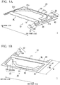
- FIG. 1A and FIG. 1B a door inner panel 1 according to the first embodiment of the present invention will be described with reference to FIG. 1A and FIG. 1B .
- FIG. 1A is a perspective view of the door inner panel 1 according to the present embodiment seen from the inside of a car
- FIG. 1B is a perspective view of the door inner panel 1 according to the present embodiment seen from the outside of the car.
- the door inner panel 1 includes a first panel portion 10, a second panel portion 20, a flat sheet portion 30, and a flange portion 40.
- a direction perpendicular to a surface of the flange portion 40 is referred to as a pressing direction.
- the first panel portion 10 has a first top sheet portion 11 being formed at a location separated from the flange portion 40 in the pressing direction and a first standing wall portion 12 connected to an end edge of the first top sheet portion 11.
- the first standing wall portion 12 is a portion which is provided so as to face a pillar or the like of a car body and enhances the sealing property of the inside of the car.
- the first standing wall portion 12 includes top sheet portion-side first standing wall portions 12a that bend from sidelines of the first top sheet portion 11 on car front side and rear side and extend in the pressing direction, flange portion-side first standing wall portions 12b that bend from the flange portion 40 and extend in the pressing direction, and first level difference portions 12c connecting the top sheet portion-side first standing wall portions 12a and the flange portion-side first standing wall portions 12b.
- the first level difference portions 12c are formed substantially parallel to the surface of the flange portion 40 between the flange portion 40 and the first top sheet portion 11.
- the second panel portion 20 is formed separated from the first panel portion 10 through the flat sheet portion 30 in the case of being seen in a planar view.
- the second panel portion 20 has a second top sheet portion 21 being formed at a location separated from the flange portion 40 in the pressing direction and a second standing wall portion 22 connected to an end edge of the second top sheet portion 21.
- the second standing wall portion 22 is, similar to the first standing wall portion 12, a portion which is provided so as to face the pillar or the like of the car body and enhances the sealing property of the inside of the car.
- the second standing wall portion 22 includes a top sheet portion-side second standing wall portion 22a that bends from four outside sidelines 21a, 21b, 21c, and 21d of the second top sheet portion 21 and extends in the pressing direction, a flange portion-side second standing wall portion 22b that bends from the flange portion 40 and extends in the pressing direction, and a second level difference portion 22c connecting the top sheet portion-side second standing wall portion 22a and the flange portion-side second standing wall portion 22b.
- the second level difference portion 22c is formed substantially parallel to the surface of the flange portion 40 between the flange portion 40 and the second top sheet portion 21.
- the top sheet portion-side second standing wall portion 22a is continuously formed along the four outside sidelines 21a, 21b, 21c, and 21d, which are adjacent to each other, of the second top sheet portion 21, and thus the stiffness of the door inner panel 1 can be enhanced.
- the first top sheet portion 11 has a quadrilateral planar shape
- the second top sheet portion 21 has a pentagonal planar shape. Furthermore, a sideline of the first top sheet portion 11 on a car upper side forms a belt line BL.
- an opening portion 50 is formed so as to let a circumferential edge portion adjacent to the four outside sidelines 21a, 21b, 21c, and 21d of the second top sheet portion 21 remain.
- An acoustic speaker, a knob, and the like are attached to a location corresponding to the opening portion 50.
- the opening portion 50 is formed in the second top sheet portion 21 as in the door inner panel 1 according to the present embodiment, it becomes easy to carry out stretch flange deformation by the widening of the opening portion 50 during press working. Therefore, not only is weight reduction achieved by the cutting of the weight, but the generation of forming defects such as cracks or wrinkles can be limited.
- the flange portion 40 is formed so as to connect the flange portion-side first standing wall portion 12b and the flange portion-side second standing wall portion 22b in the periphery of the first panel portion 10 and the second panel portion 20.
- the flat sheet portion 30 is a portion that plays a role of a door impact beam and is formed in a band shape so as to partition the first panel portion 10 and the second panel portion 20 in a planar view.
- the flat sheet portion 30 is formed in a band shape (a linear shape), and thus the shape of a die is simple, and the manufacturing costs can be limited.
- the flat sheet portion 30 is integrally formed with the flange portion 40. Therefore, it is not necessary to attach a separate door impact beam to the door inner panel, and thus it is possible to realize the weight reduction of the door inner panel. Furthermore, end portions of the flat sheet portion 30 are preferably formed on the same surface as the flange portion 40.
- the ratio W1/W of W1 to W is preferably 0.05 or more and 0.6 or less.
- a preferred lower limit of the ration W1/W is 0.05.
- a preferred upper limit of the ratio W1/W is 0.6.
- the width of the minimum width portion is set to 30 mm or more and the width of the maximum width portion is set to 200 mm or less.
- the flat sheet portion 30 is preferably provided in a region corresponding to a door lock striker of the car. As shown in FIG. 1A and FIG. 1B , in the region provided with the flat sheet portion 30, there is a gap between the first standing wall portion 12 and the second standing wall portion 22. This is because a hook for door lock or the like can be stored in this gap.
- both ends of the flat sheet portion 30 are connected to the flange portion 40, and thus, when the door inner panel 1 is combined with a door outer panel or the like, the flat sheet portion 30 is provided at a location close to the door outer panel. Therefore, the impact characteristics of a door can be improved. Hereinafter, this fact will be described in detail.
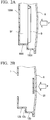
- FIG. 2A is a schematic view of a cross section of an ordinary car side door perpendicular to a car body up and down direction.
- the side door is structured by combining a door outer panel A and a door inner panel 1000.
- a space SP is a space between the door outer panel A and the door inner panel 1000.
- an acoustic speaker, a window, a window-driving apparatus, and the like are stored.
- a load P (a white arrow in FIG. 2A ) is exerted on the door outer panel A. Due to the load P, the door outer panel A deforms, and a standing wall portion 1001 of the door inner panel 1000 deforms. The standing wall portion 1001 of the door inner panel 1000 absorbs the impact energy attributed to the load P.
- the material of the door inner panel 1000 of the related art is a soft steel sheet having a low strength. This is because, as described above, the shape of the door inner panel is complicated and working of the door inner panel is difficult.
- the soft steel sheet is, for example, a steel sheet having a tensile strength of approximately 270 MPa. Therefore, it is indispensable to reinforce car side doors of the related art with a separate reinforcement member such as a door impact beam D shown in FIG. 2A .
- the door outer panel A comes into contact with the door impact beam D when the door outer panel A deforms toward the inside of the car due to the load P. Therefore, the impact energy is absorbed not only by the door inner panel 1000 but also by the door impact beam D, and thus the impact characteristics of the side door improve.
- the door impact beam D which is a separate member needs to be attached to the door inner panel 1000, and thus assembled doors of the related art are heavy, and the absorbed energy per unit weight (absorbed energy weight efficiency) is poor.
- the attachment of a separate member is required, and thus the manufacturing costs of doors of the related art are high, and the production efficiency is also low.
- FIG. 2B is a schematic view of a cross section of a side door to which the door inner panel 1 according to the present embodiment is applied perpendicular to the car body up and down direction.
- the side door includes the door inner panel 1 and the door outer panel A.
- the door outer panel A is disposed on a car outside of the door inner panel 1 and joined with the door inner panel 1.
- the flat sheet portion 30 of the door inner panel 1 is disposed at a location close to the door outer panel A. Therefore, when the door outer panel A deforms toward the inside of a car due to a load, the door outer panel A comes into contact with the flat sheet portion 30. Therefore, the impact energy is first absorbed in the flat sheet portion 30 out of the respective members of the door inner panel 1, and thus the impact characteristics of the side door improve.
- the flat sheet portion 30 of the door inner panel 1 according to the present embodiment functions as an alternative of the door impact beam, and thus side doors to which the door inner panel 1 according to the present embodiment is applied have excellent impact characteristics even without having the door impact beam.
- the door inner panel 1 according to the present embodiment is obtained by press forming using the steel sheet S as a blank material, but the characteristics of the steel sheet S are preferably selected depending on whether hot press forming is carried out or cold press forming is carried out.
- the carbon content (C content) of the steel sheet S is preferably 0.11 % or more and 0.35% or less by mass%.
- the C content is 0.11% or more, it is possible to exhibit favorable hardenability, and it becomes easy to set the tensile strength of the door inner panel 1 to 1,200 MPa or more, which is preferable.
- the C content is more preferably 0.15% or more.
- the C content is 0.35% or less, welding defects can be limited, which is preferable.
- the C content is more preferably 0.30% or less.
- Components such as Si, Mn, P, S, Al, B, and the like may be appropriately adjusted.
- the sheet thickness is preferably uniform in the first top sheet portion 11 and the second top sheet portion 21.
- T1 MAX the maximum sheet thickness portion in the first top sheet portion 11
- T1 MIN the minimum sheet thickness portion in the first top sheet portion 11
- T2 MAX the maximum sheet thickness portion in the second top sheet portion 21
- T2 MIN the minimum sheet thickness portion in the second top sheet portion 21
- a steel sheet having a tensile strength of 340 MPa to 980 MPa is preferably used.
- the carbon content (C content) of the steel sheet S is preferably 0.001% to 0.150%, by mass%.
- the C content is 0.001% or more, it is easy to set the tensile strength of the door inner panel 1 to 340 MPa or more, which is preferable.
- the C content is more preferably 0.08% or more.
- the C content is 0.150% or less, favourable pressing workability can be exhibited, which is preferable.
- the C content is more preferably 0.12% or less.
- the components such as Si, Mn, P, S, Al, B, and the like may be appropriately adjusted.
- the sheet thickness is preferably uniform in the first top sheet portion 11 and the second top sheet portion 21.
- T1 MAX the maximum sheet thickness portion in the first top sheet portion 11
- T1 MIN the minimum sheet thickness portion in the first top sheet portion 11
- T2 MAX the maximum sheet thickness portion in the second top sheet portion 21
- T2 MIN the minimum sheet thickness portion in the second top sheet portion 21
- the sheet thickness in order to set the sheet thickness to be uniform in the first top sheet portion 11 and the second top sheet portion 21 even in the case of employing any of hot press forming or cold press forming, it is preferable to employ a manufacturing method in which the working of the first top sheet portion 11 and the second top sheet portion 21 is completed after the working of the first level difference portion 12c and the second level difference portion 22c is completed as in a method for manufacturing a door inner panel described below.
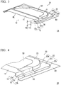
- FIG. 3 is a perspective view of a door inner panel 1A according to a first modification example seen from an inside of a car.
- the door inner panel 1A is different from the door inner panel 1 according to the first embodiment in terms of the fact that both ends of the flat sheet portion 30 are connected to the first level difference portion 12c and the second level difference portion 22c.
- both ends of the flat sheet portion 30 are provided so as to be integrated with the first level difference portion 12c and the second level difference portion 22c.
- the first panel portion 10 is connected with the second panel portion 20 through the flange portion 40 and the level difference portions (the first level difference portions 12c and the second level difference portion 22c). Therefore, in the door inner panel 1A, compared with the door inner panel 1 according to the first embodiment, a region in which the first panel portion 10 is connected with the second panel portion 20 is larger. Therefore, the door inner panel 1A has a higher stiffness than the door inner panel 1 according to the above-described embodiment.
- the flat sheet portion 30 of the door inner panel 1A is disposed at a location farther than the door outer panel than the flat sheet portion 30 of the door inner panel 1 according to the above-described embodiment. Therefore, the door inner panel 1 according to the above-described embodiment is preferred from the viewpoint of the impact characteristics of the door.
- the disposition of the flat sheet portion 30 is appropriately set in consideration of the impact characteristics of doors, the stiffness of the door inner panel, and the like.
- the door inner panel 1A according to this modification example preferably satisfies conditions of h2 ⁇ 40 mm and hl/h2 ⁇ 0.8. This is because, in the case of h2 ⁇ 40 mm, the space SP that stores a window and the like is too small. In the case of h1/h2 ⁇ 0.8, the distance between the level difference portions (the first level difference portion 12c and the second level difference portion 22c) and the top sheet portion (the first top sheet portion 11 and the second top sheet portion 21) is close, and thus the sealing property of the inside of the car becomes poor.
- FIG. 4 is a perspective view showing a door inner panel 1B according to a second modification example.
- a reinforcement component 60 connecting the first panel portion 10 and the second panel portion 20 is provided in order to enhance the stiffness.
- the reinforcement component 60 is a member that connects the first level difference portion 12c and the second level difference portion 22c of the first standing wall portion 12 and the second standing wall portion 22. Therefore, the first panel portion 10 is connected to the second panel portion 20, and the stiffness of the entire door inner panel 1B enhances.
- the reinforcement component 60 is, for example, a sheet-like component obtained by pressing a steel sheet.
- the reinforcement component 60 may be joined to the first panel portion 10 and the second panel portion 20 by means of, for example, welding.
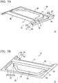
- FIG. 5A and FIG. 5B show a door inner panel 1C according to a third modification example.
- FIG. 5A is a perspective view of the door inner panel 1C seen from an inside of a car
- FIG. 5B is a perspective view of the door inner panel 1C seen from an outside of the car.
- the door inner panel 1C according to this third modification example is different from the door inner panel 1 according to the first embodiment in terms of the fact that the flat sheet portion 30 has a wall portion 31.
- the other constitutions of the door inner panel 1C according to this modification example are the same as those of the door inner panel 1 according to the above-described embodiment.
- the flat sheet portion 30 has the wall portion 31, and thus the cross-sectional shape of the flat sheet portion 30 is a U-like shape. Therefore, compared with the flat sheet portion 30 of the door inner panel 1 according to the above-described embodiment which has a flat shape, the flat sheet portion 30 has an increased cross-sectional secondary moment. That is, the impact energy being absorbed by the flat sheet portion 30 having the wall portion 31 is greater than the impact energy being absorbed by the flat sheet portion 30 of the door inner panel 1 according to the above-described embodiment.
- the wall portion 31 connects the first standing wall portion 12 and the second standing wall portion 22. Therefore, it is possible to increase the stiffness of the entire door inner panel 1C.
- the method for manufacturing a door inner panel according to the present embodiment is a method of press-forming the door inner panel 1 according to the first embodiment and includes a step of preparing the steel sheet S as a blank material (blank preparation step) and a step of pressing the steel sheet S in a cold or hot manner using a pressing apparatus (press working step).
- FIG. 6A and FIG. 6B are cross-sectional views schematically showing a pressing apparatus 100 that is used in the press working step of the method for manufacturing a door inner panel according to the present embodiment.
- FIG. 6A is a cross-sectional view showing a place corresponding to the first panel portion 10 of the door inner panel 1 in the pressing apparatus 100
- FIG. 6B is a view in an A-A arrow direction in FIG. 6A .
- the pressing apparatus 100 includes an inside punch 101, an outside punch 102, a blank holder 103, and a die 104.
- the inside punch 101 and the outside punch 102 are pressed into a dent of the die 104 in a state in which the steel sheet S is sandwiched and fixed by the blank holder 103 and the die 104, whereby the steel sheet S can be formed to a shape of the door inner panel 1 shown in FIG. 1 .
- the inside punch 101 has a first inside punch 101a having a shape corresponding to that of the first top sheet portion 11 and a second inside punch 101b having a shape corresponding to that of the second top sheet portion 21.
- the first inside punch 101a and the second inside punch 101b are separated from each other along a portion corresponding to the flat sheet portion.
- the inside punch 101 as described it is possible to set the press forming depth of the portion corresponding to the flat sheet portion 30 to be shallower than the press forming depth of a portion corresponding to the first top sheet portion 11 and the second top sheet portion 21.
- first inside punch 101a and the second inside punch 101b do not need to be completely separated from each other, and only the place corresponding to the flat sheet portion 30 may be formed in a groove shape in a single inside punch 101.
- the outside punch 102 is disposed outside the inside punch 101 and has a first outside punch 102a having a shape corresponding to that of the first level difference portion 12c and a second outside punch 102b having a shape corresponding to that of the second level difference portion 22c.
- the first outside punch 102a and the second outside punch 102b are separated from each other along the portion corresponding to the flat sheet portion 30, whereby it is possible to set the press forming depth of the portion corresponding to the flat sheet portion 30 to be shallower than the press forming depth of a portion corresponding to the first level difference portion 12c and the second level difference portion 22c.
- first outside punch 102a and the second outside punch 102b do not need to be completely separated from each other, and only the place corresponding to the flat sheet portion 30 may be formed in a groove shape in a single inside punch 101.
- the outside punch in which the first outside punch 102a and the second outside punch 102b are not separated from each other.
- the blank holder 103 is disposed outside the outside punch 102 so as to face the die 104 in a pressing axis direction.
- the steel sheet S can be fixed during press forming.
- the shape of the flange portion 40 of the door inner panel 1 is formed.
- the die 104 is disposed so as to face the inside punch 101, the outside punch 102, and the blank holder 103 in the pressing axis direction, and a dent having a shape corresponding to that of the door inner panel 1 is formed.
- the steel sheet is preferably formed by hot stamping in which the steel sheet S in a state of being heated is press-formed in a die and cooled in the die. Therefore, the pressing apparatus 100 may include a heating device and a cooling device.
- the characteristics of the steel sheet S being prepared are as described in the first embodiment and preferably selectively used depending on the case of hot pressing and the case of cold pressing.
- FIG. 7 is a plan view of the steel sheet S in the case of manufacturing the door inner panel 1 shown in FIG. 1A and FIG. 1B .
- the steel sheet S has a first flat sheet portion S1, a second flat sheet portion S2, a third flat sheet portion S3, and opening portions S4.
- the first flat sheet portion S1 is a portion corresponding to the first panel portion 10.
- the second flat sheet portion S2 is a portion corresponding to the second panel portion 20.
- the third flat sheet portion S3 is a portion corresponding to the flat sheet portion 30.
- the opening portions S4 are portions corresponding to the opening portion 50.
- a region indicated by hatched lines in FIG. 7 is a region corresponding to the inside punch 101.
- a region indicated by crossing hatched lines in FIG. 7 is a region corresponding to the outside punch 102.
- the opening portions S4 are provided between the first flat sheet portion S1 and the third flat sheet portion S3 and between the second flat sheet portion S2 and the third flat sheet portion S3.
- stretch flange deformation is easy.
- the opening portions S4 are not necessary.
- the steel sheet having the above-described shape is obtained by punching the steel sheet.
- the door inner panel 1 shown in FIG. 1A and FIG. 1B can be formed as long as the steel sheet has ductility and a stretch flange property that materials having a tensile strength of approximately 340 to 980 MPa have.
- the flat sheet portion 30 has the wall portion 31, and thus a steel sheet S shown in FIG. 8 is preferably used.
- the inside punch 101 and the outside punch 102 further work a part of the third flat sheet portion S3 of the steel sheet S. Therefore, the wall portion 31 of the flat sheet portion 30 is formed.
- a region indicated by hatched lines in FIG. 8 is a region corresponding to the inside punch 101.
- a region indicated by crossing hatched lines in FIG. 8 is a region corresponding to the outside punch 102.
- the inside punch 101 is configured to work a region in the first flat sheet portion S1 of the steel sheet S which is formed to the first top sheet portion 11 and a region in the second flat sheet portion S2 of the steel sheet S which is formed to the second top sheet portion 21, and the outside punch 102 is configured to work a region in the first flat sheet portion S1 of the steel sheet S which is formed to the first level difference portion 12c and a region in the second flat sheet portion S2 of the steel sheet S which is formed to the second level difference portion 22c.
- the steel sheet S is heated before the press working.
- the steel sheet S is heated using a heating device not shown.
- the steel sheet S needs to be heated to the Al point or higher of the material thereof, but preferably heated to the Ac3 point or higher in order to more reliably obtain the quenching effect.
- the heating temperature is, for example, 700°C to 900°C.
- the heating temperature is appropriately set depending on the material, the forming difficulty, and the like.
- the steel sheet S is heated and softened, and thus it is possible to form the steel sheet to a complicated shape.
- the press working step the working of the steel sheet S by the outside punch 102 is completed earlier than the working of the steel sheet S by the inside punch 101. Therefore, it is possible to suppress the generation of forming defects such as cracks or wrinkles in the formed door inner panel.
- FIG. 9A to FIG. 9C are cross-sectional views schematically showing the press working step of the method for manufacturing a door inner panel according to the present embodiment.
- FIG. 9A shows a stage of holding the steel sheet S placed on the die 104 using the blank holder 103 (initial stage).
- FIG. 9B shows a state in which the holding by the outside punch 102 is completed (middle stage).
- FIG. 9C shows a state in which the holding by the inside punch 101 is completed (final stage)
- the interval between the blank holder 103 and the die 104 is preferably larger than the thickness of the steel sheet S. That is, a gap is provided between the steel sheet S and the blank holder 103.
- the size of the gap is, for example, 0.1 mm.
- the pressing by the outside punch 102 is completed, and the steel sheet S is in a state of being draw-formed by the outside punch 102 and the die 104.
- the inside punch 101 is as high as the outside punch 102.
- the pressing of the steel sheet S by the inside punch 101 begins as soon as the pressing of the steel sheet S by the outside punch 102 is completed.
- the height location of the inside punch 101 is as high as the height of the outside punch 102.
- the height location of the inside punch 101 at this time may be at a lower location than the outside punch 102.
- the pressing of the steel sheet S by the inside punch 101 may begin before the pressing of the steel sheet S by the outside punch 102 is completed.
- the height location of the inside punch 101 may be at a lower location than the outside punch 102. That is, the pressing of the steel sheet S by the inside punch 101 may begin after the pressing of the steel sheet S by the outside punch 102 is completed.
- the pressing by the inside punch 101 is not completed earlier before the pressing by the outside punch 102. Meanwhile, the steel sheet S simply needs to be held by the blank holder 103 and the die 104 until the forming by the outside punch is completed.
- FIG. 9A to FIG. 9C and FIG. 10A to FIG. 10C show cases in which the steel sheet S does not have any opening portions; however, in a case in which the steel sheet S has an opening portion, after the completion of the pressing by the outside punch 102, the material moves from the top sheet portion to the vertical wall in the middle of the forming by the inside punch 101 and stretch-flange-deforms, and thus it becomes possible to further suppress cracks.
- the pressing of the steel sheet S by the outside punch 102 is completed, and then the pressing of the steel sheet S by the inside punch 101 is completed. Therefore, when the pressing by the outside punch 102 is completed, and thus the steel sheet S is draw-formed, a portion of the steel sheet S pressed by the outside punch 102 is restrained by the outside punch 102. Therefore, it is possible to suppress wrinkles and the like being generated in the vicinity of the level difference portion of the door inner panel. Hereinafter, this fact will be described below.
- FIG. 11 is a cross-sectional view showing a state in the middle of press working using an ordinary pressing apparatus 200.
- FIG. 11 shows a part of a die 220 of the ordinary pressing apparatus 200 in an enlarged manner.
- the punch 210 is not separated into an inside punch and an outside punch. Therefore, when a punch 210 is moved down, a portion V1 of a steel sheet V is not restrained by the punch 210 and the die 220. That is, the portion V1 of the steel sheet V does not come into contact with the punch 210 and the die 220.
- the portion V1 of the steel sheet V is not restrained by the punch 210 and the die 220. Therefore, the portion V1 of the steel sheet V is likely to warp and wrinkle.
- the steel sheet is cooled by the contact between the steel sheet and the punch, the die, or the like. Therefore, in the stage in the middle of the press working shown in FIG. 11 , the portion V1 of the steel sheet V is not cooled. The portion V1 of the steel sheet V is cooled when the punch 210 is further pressed down from the location shown in FIG. 11 .
- the portion V1 of the steel sheet V is cooled later than the other portions.
- the pressing apparatus 100 having the inside punch 101 and the outside punch 102 is used. Therefore, the first top sheet portion 11 (of the second top sheet portion 21) and the first level difference portion 12c (or the second level difference portion 22c) of the door inner panel 1 as shown in FIG. 1A and FIG. 1B are formed using separate punches.
- the pressing by the outside punch 102 is completed earlier than the pressing by the inside punch 101. Therefore, when one punch forms the top sheet portion, the other punch pressed the level difference portion of the door inner panel 1. Therefore, in the forming of the top sheet portion, the area of a portion of the steel sheet S which is not restrained becomes small, and it is possible to suppress the generation of wrinkles and the like in the door inner panel 1.
- the door inner panels for a car side door have been described.
- the door inner panel of the present embodiment is not limited to panels for a side door.
- the door inner panel of the present embodiment can also be applied to doors other than side doors such as rear doors.
- the door inner panel of the present embodiment is not limited to panels for a car.
- the door inner panel can be applied to products for which excellent impact characteristics are demanded. Examples of such products include cars, construction machinery, aircrafts, and the like.
- the material of the door inner panel is a steel sheet
- the material of the door inner panel is not limited to steel sheets, and a metal sheet may be used.
- the metal sheet include an aluminum sheet, an aluminum alloy sheet, a multilayer steel sheet, a magnesium sheet, and the like.
- a tailored blank may be used as the steel sheet. Tailored blanks are roughly classified into tailor welded blanks (hereinafter, also referred to as "TWB") and tailor rolled blanks (hereinafter, also referred to as "TRB").
- TWB is obtained by integrating a plurality of steel sheets having different sheet thicknesses, different tensile strengths, and the like by means of welding (for example, butt welding).
- TRB has a sheet thickness that is changed by changing the interval between rolling rolls during the manufacturing of a steel sheet.
- the use of this tailored blank enables an increase in the strength only in necessary places, and thus it is also possible to reduce the sheet thickness.
- door inner panels for which the tailored blank is used can also be applied to cars. Therefore, the impact characteristics of door inner panels can be improved, and furthermore, the weight reduction can be desired.
- the flat sheet portion 30 is formed to a flat band shape (linear shape), but the flat sheet portion 30 may be formed by being bent in a planar view and a recessed portion or a protruded portion may be formed.
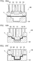
- FIG. 12 shows an example of a door inner panel 1' having a flat sheet portion 30' in which a recessed portion is formed. In this case, it is possible to enhance the cross-sectional secondary moment of the flat sheet portion 30 and improve the strength of the door inner panel 1. In addition, both a recessed portion and a protruded portion may be formed.
- the flat sheet portion 30 extends parallel to the belt line BL in a planar view, but the flat sheet portion 30 may not extend parallel to the belt line BL. That is, the flat sheet portion 30 may have an angle with respect to the belt line BL.
- the second standing wall portion 22 which bends and extends from the four outside sidelines 21a, 21b, 21c, and 21d of the second top sheet portion 21 is provided, but the second standing wall portion 22 may be bend and extend from each of two or more adjacent sidelines out of the outside sidelines of the second top sheet portion 21.
- the planar shape of the first top sheet portion 11 is a quadrilateral shape
- the planar shape of the second top sheet portion 21 is a pentagonal shape.
- the planar shapes of the first top sheet portion 11 and the second top sheet portion 21 may be appropriately set depending on the shape of a car.
- the opening portion 50 is provided only at one place in the second top sheet portion 21, but the number of the opening portions 50 is not limited to one, and a plurality of opening portions 50 may be formed in the second top sheet portion 21.
- the opening portion 50 may also be formed in the first top sheet portion 11.
- the shape of the opening portion 50 may be a circular shape, an elliptical shape, a polygonal shape, or the like and is not particularly limited.
- the opening portion 50 may not be formed in the second top sheet portion 21. In a case in which the second top sheet portion 21 can be formed without the opening portion 50 or a speaker and the like are not required, the opening portion 50 is not necessary.
- first standing wall portion 12 and the second standing wall portion 22 extend perpendicularly to the first top sheet portion 11 and the second top sheet portion 21 has been described, but the standing wall portions may not be strictly perpendicular to the top sheet portions.
- TS after HS refers to a tensile strength in a case in which the steel sheet was press-formed in a state of being heated to the Ac3 point or higher and cooled in a die.
- the steel sheets A to F were press-formed to door inner panels having the shape shown in FIG. 1A and FIG. 1B using a pressing apparatus shown in FIG. 6A and FIG. 6B .
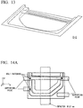
- FIG. 14A First, as shown in FIG. 14A , three points in the door inner panel were fastened using bolts. In addition, an impactor with R of 127 mm was impacted as shown in FIG. 14B , thereby obtaining the absorption energy (J) with an impact dislocation of 100 mm. In addition, a value obtained by dividing the absorption energy by the weight of the door inner panel including a reinforcement portion or a reinforcement member was considered as the weight efficiency.
- Table 2 shows that, according to the present invention examples, compared with the cases in which the reinforcement member was separately attached to the door inner panel, it becomes possible to increase the absorption energy per unit weight by maintaining the operation efficiency.
Landscapes
- Engineering & Computer Science (AREA)
- Mechanical Engineering (AREA)
- Physics & Mathematics (AREA)
- Thermal Sciences (AREA)
- Shaping Metal By Deep-Drawing, Or The Like (AREA)
- Securing Of Glass Panes Or The Like (AREA)
- Body Structure For Vehicles (AREA)
Applications Claiming Priority (2)
| Application Number | Priority Date | Filing Date | Title |
|---|---|---|---|
| JP2016059198 | 2016-03-23 | ||
| PCT/JP2017/010744 WO2017164079A1 (ja) | 2016-03-23 | 2017-03-16 | ドアインナーパネル及びドアインナーパネル製造方法 |
Publications (2)
| Publication Number | Publication Date |
|---|---|
| EP3434501A1 true EP3434501A1 (de) | 2019-01-30 |
| EP3434501A4 EP3434501A4 (de) | 2019-11-27 |
Family
ID=59900256
Family Applications (1)
| Application Number | Title | Priority Date | Filing Date |
|---|---|---|---|
| EP17770121.6A Pending EP3434501A4 (de) | 2016-03-23 | 2017-03-16 | Türinnenverkleidung und verfahren zur herstellung einer türinnenverkleidung |
Country Status (10)
| Country | Link |
|---|---|
| US (1) | US10857858B2 (de) |
| EP (1) | EP3434501A4 (de) |
| JP (1) | JP6206629B1 (de) |
| KR (1) | KR102032185B1 (de) |
| CN (1) | CN108778806B (de) |
| BR (1) | BR112018068624A2 (de) |
| CA (1) | CA3017554C (de) |
| MX (1) | MX2018011414A (de) |
| RU (1) | RU2699435C1 (de) |
| WO (1) | WO2017164079A1 (de) |
Families Citing this family (8)
| Publication number | Priority date | Publication date | Assignee | Title |
|---|---|---|---|---|
| CA3059156A1 (en) * | 2017-04-10 | 2018-10-18 | Nippon Steel Corporation | Structural member for automobiles |
| JP6777053B2 (ja) * | 2017-10-13 | 2020-10-28 | Jfeスチール株式会社 | プレス成形装置及び方法 |
| JP6809435B2 (ja) * | 2017-10-26 | 2021-01-06 | Jfeスチール株式会社 | プレス成形装置及び方法 |
| DE102017127158A1 (de) * | 2017-11-17 | 2019-05-23 | HoDforming GmbH | Verfahren zum Umformen eines Blechrohlings, z. B. einer Platine oder eines Hohlkörperrohlings als Werkstück in einem Umformwerkzeug |
| JP7155578B2 (ja) * | 2018-03-30 | 2022-10-19 | マツダ株式会社 | 加工装置及び方法 |
| JP6677289B1 (ja) * | 2018-12-12 | 2020-04-08 | Jfeスチール株式会社 | プレス成形方法 |
| DE102021103999B3 (de) * | 2021-02-19 | 2022-03-24 | Benteler Automobiltechnik Gmbh | Fahrzeugtür aus einem Panzerstahl |
| US11427066B1 (en) * | 2021-03-10 | 2022-08-30 | Honda Motor Co., Ltd. | Door structure |
Family Cites Families (38)
| Publication number | Priority date | Publication date | Assignee | Title |
|---|---|---|---|---|
| SU1196076A1 (ru) | 1983-11-02 | 1985-12-07 | Всесоюзный Ордена Трудового Красного Знамени Заочный Политехнический Институт | Способ выт жки кузовных деталей |
| JPH0617087B2 (ja) * | 1984-12-28 | 1994-03-09 | 橋本フオ−ミング工業株式会社 | 自動車のドアパネル用補強桁部材 |
| JP2520478B2 (ja) * | 1989-07-03 | 1996-07-31 | 日産自動車株式会社 | パネル部品の成形方法 |
| US5446999A (en) * | 1993-06-28 | 1995-09-05 | Nissan Motor Co., Ltd. | Vehicle door assembly having an easily removable outside panel |
| JPH07329570A (ja) * | 1994-06-10 | 1995-12-19 | Nissan Motor Co Ltd | 車両用ドア構造 |
| US5600991A (en) | 1995-02-10 | 1997-02-11 | Ogihara America Corporation | Stretch controlled forming mechanism and method for forming multiple gauge welded blanks |
| AU681982B2 (en) * | 1995-02-10 | 1997-09-11 | Ogihara America Corporation | Stretch controlled forming mechanism and method for forming multiple guage welded blanks |
| US5908216A (en) * | 1995-12-22 | 1999-06-01 | Joalto Design, Inc. | Side intrusion beam with four points of connection |
| RU2116854C1 (ru) | 1997-03-27 | 1998-08-10 | Акционерное общество "АвтоВАЗ" | Способ штамповки деталей кузова эластичной средой по жесткой матрице |
| KR19990003105U (ko) | 1997-06-30 | 1999-01-25 | 양재신 | 강성을 향상시킨 자동차 도어 이너 패널 |
| JP2001088553A (ja) * | 1999-09-21 | 2001-04-03 | Mazda Motor Corp | 車両の側部車体構造 |
| SE522423C2 (sv) * | 2002-08-08 | 2004-02-10 | Ssab Hardtech Ab | Fordonsdörr och sätt att tillverka sådan |
| US7040688B2 (en) | 2003-04-29 | 2006-05-09 | General Motors Corporation | Vehicle door |
| DE10359655A1 (de) * | 2003-12-18 | 2005-07-21 | Bayerische Motoren Werke Ag | Fahrzeugtür mit einer Versteifungsstrebe |
| CN103434371B (zh) * | 2004-06-23 | 2016-03-30 | 英提尔汽车系统公司 | 结构性门模组 |
| JP4622635B2 (ja) * | 2005-04-01 | 2011-02-02 | トヨタ自動車株式会社 | 車両用ドア構造 |
| DE102005030507B4 (de) * | 2005-06-28 | 2008-04-03 | Benteler Automobiltechnik Gmbh | Türstruktur eines Kraftfahrzeugs |
| JP2007296953A (ja) | 2006-04-28 | 2007-11-15 | Toyota Motor Corp | サイドドア構造 |
| JP4240064B2 (ja) * | 2006-06-09 | 2009-03-18 | トヨタ自動車株式会社 | 車両用ドア構造 |
| JP4305484B2 (ja) * | 2006-09-26 | 2009-07-29 | 日産自動車株式会社 | ドアパネル構造およびドアパネル製造方法 |
| JP2008094353A (ja) | 2006-10-16 | 2008-04-24 | Toyota Motor Corp | 車両用ドア及びパネル部材荷重吸収構造 |
| DE102007032143A1 (de) * | 2007-07-09 | 2009-01-15 | Thyssenkrupp Drauz Nothelfer Gmbh | Tür eines Kraftfahrzeuges |
| JP4368915B2 (ja) * | 2007-07-24 | 2009-11-18 | 本田技研工業株式会社 | 車両用ドアの構造 |
| JP5035218B2 (ja) * | 2007-12-27 | 2012-09-26 | 豊田合成株式会社 | 自動車用ドア |
| JP5001907B2 (ja) * | 2008-06-23 | 2012-08-15 | 本田技研工業株式会社 | 車両のロック部構造 |
| US7866730B2 (en) * | 2008-11-14 | 2011-01-11 | Magna International Inc. | Thermoformed twinsheet molded vehicle door system |
| RU81932U1 (ru) | 2008-12-29 | 2009-04-10 | Общество с ограниченной ответственностью "СТИГР-ВАГРЕМ" (ООО "СТИГР-ВАГРЕМ") | Дверь салонная пассажирского вагона |
| MX2012008095A (es) * | 2010-01-13 | 2012-07-30 | Nippon Steel Corp | Panel. |
| CN201881860U (zh) * | 2010-08-17 | 2011-06-29 | 芜湖众力部件有限公司 | 一种汽车门板内开面板 |
| JP2013112133A (ja) | 2011-11-28 | 2013-06-10 | Toyota Motor Corp | 車両用ドア構造 |
| JP2013166474A (ja) * | 2012-02-15 | 2013-08-29 | Toyota Motor Corp | 車両側部構造 |
| DE102012004628A1 (de) * | 2012-03-06 | 2012-11-08 | Daimler Ag | Fahrzeugtür mit einer Strukturversteifung |
| FR2994544B1 (fr) * | 2012-08-16 | 2015-06-26 | Renault Sa | Structure de porte de vehicule automobile munie d'un renfort, renfort, porte equipee de la structure de porte et vehicule associes |
| JP5826736B2 (ja) * | 2012-11-21 | 2015-12-02 | 株式会社豊田自動織機 | 車両用ドアの補強構造 |
| MX2016006868A (es) * | 2013-11-26 | 2016-08-17 | Nippon Steel & Sumitomo Metal Corp | Panel que tiene rebajes y protuberancias. |
| CN107107149B (zh) * | 2014-12-25 | 2020-06-12 | 日本制铁株式会社 | 门内板和板状成形品的制造方法 |
| CA2998314A1 (en) * | 2015-09-18 | 2017-03-23 | Nippon Steel & Sumitomo Metal Corporation | Panel-like formed product and manufacturing method thereof |
| KR102115465B1 (ko) * | 2016-01-28 | 2020-05-26 | 닛폰세이테츠 가부시키가이샤 | 패널형 성형품, 차량용 도어, 및, 패널형 성형품의 제조 방법 |
-
2017
- 2017-03-16 WO PCT/JP2017/010744 patent/WO2017164079A1/ja not_active Ceased
- 2017-03-16 RU RU2018134787A patent/RU2699435C1/ru not_active IP Right Cessation
- 2017-03-16 CA CA3017554A patent/CA3017554C/en not_active Expired - Fee Related
- 2017-03-16 MX MX2018011414A patent/MX2018011414A/es unknown
- 2017-03-16 EP EP17770121.6A patent/EP3434501A4/de active Pending
- 2017-03-16 US US16/085,872 patent/US10857858B2/en active Active
- 2017-03-16 JP JP2017535466A patent/JP6206629B1/ja active Active
- 2017-03-16 BR BR112018068624A patent/BR112018068624A2/pt not_active IP Right Cessation
- 2017-03-16 CN CN201780018752.2A patent/CN108778806B/zh active Active
- 2017-03-16 KR KR1020187028070A patent/KR102032185B1/ko active Active
Also Published As
| Publication number | Publication date |
|---|---|
| JPWO2017164079A1 (ja) | 2018-04-05 |
| US20190100084A1 (en) | 2019-04-04 |
| US10857858B2 (en) | 2020-12-08 |
| BR112018068624A2 (pt) | 2019-02-05 |
| KR20180118723A (ko) | 2018-10-31 |
| RU2699435C1 (ru) | 2019-09-05 |
| MX2018011414A (es) | 2019-01-10 |
| CN108778806A (zh) | 2018-11-09 |
| JP6206629B1 (ja) | 2017-10-04 |
| CN108778806B (zh) | 2021-08-24 |
| CA3017554C (en) | 2020-08-04 |
| KR102032185B1 (ko) | 2019-10-15 |
| EP3434501A4 (de) | 2019-11-27 |
| WO2017164079A1 (ja) | 2017-09-28 |
| CA3017554A1 (en) | 2017-09-28 |
Similar Documents
| Publication | Publication Date | Title |
|---|---|---|
| US10857858B2 (en) | Door inner panel and method for manufacturing door inner panel | |
| JP6921909B2 (ja) | パネル状成形品 | |
| US10898938B2 (en) | Method for manufacturing panel-like formed article | |
| US10239105B2 (en) | Blank steel plate, production method and production device therefor, and production method for press-formed product using blank steel plate | |
| US11027781B2 (en) | Hot-stamping formed article, structural member using the same, and manufacturing method of hot-stamping formed article | |
| KR101814943B1 (ko) | 프레스 성형품 및 프레스 성형품의 제조 방법 및 프레스 성형품의 제조 장치 | |
| JP6288378B2 (ja) | パネル状成形品、車両用ドア、及び、パネル状成形品の製造方法 | |
| US20200038934A1 (en) | Press formed product, automobile structural member with the press formed product, and method for producing press formed product | |
| JP2011062713A (ja) | 曲がり閉断面構造部品およびその製造方法 | |
| KR102330195B1 (ko) | 성형체, 구조 부재, 및 성형체의 제조 방법 | |
| RU2688112C1 (ru) | Штампованное изделие и способ его конструирования |
Legal Events
| Date | Code | Title | Description |
|---|---|---|---|
| STAA | Information on the status of an ep patent application or granted ep patent |
Free format text: STATUS: THE INTERNATIONAL PUBLICATION HAS BEEN MADE |
|
| PUAI | Public reference made under article 153(3) epc to a published international application that has entered the european phase |
Free format text: ORIGINAL CODE: 0009012 |
|
| STAA | Information on the status of an ep patent application or granted ep patent |
Free format text: STATUS: REQUEST FOR EXAMINATION WAS MADE |
|
| 17P | Request for examination filed |
Effective date: 20181018 |
|
| AK | Designated contracting states |
Kind code of ref document: A1 Designated state(s): AL AT BE BG CH CY CZ DE DK EE ES FI FR GB GR HR HU IE IS IT LI LT LU LV MC MK MT NL NO PL PT RO RS SE SI SK SM TR |
|
| AX | Request for extension of the european patent |
Extension state: BA ME |
|
| DAV | Request for validation of the european patent (deleted) | ||
| DAX | Request for extension of the european patent (deleted) | ||
| RAP1 | Party data changed (applicant data changed or rights of an application transferred) |
Owner name: NIPPON STEEL CORPORATION |
|
| A4 | Supplementary search report drawn up and despatched |
Effective date: 20191030 |
|
| RIC1 | Information provided on ipc code assigned before grant |
Ipc: B21D 22/22 20060101ALI20191024BHEP Ipc: B21D 24/00 20060101ALI20191024BHEP Ipc: B21D 22/26 20060101ALI20191024BHEP Ipc: B21D 53/88 20060101ALI20191024BHEP Ipc: B60J 5/00 20060101AFI20191024BHEP Ipc: B21D 22/20 20060101ALI20191024BHEP Ipc: B60J 5/04 20060101ALI20191024BHEP |
|
| STAA | Information on the status of an ep patent application or granted ep patent |
Free format text: STATUS: EXAMINATION IS IN PROGRESS |
|
| 17Q | First examination report despatched |
Effective date: 20221123 |