EP3415280A1 - Power tool with a paddle switch - Google Patents
Power tool with a paddle switch Download PDFInfo
- Publication number
- EP3415280A1 EP3415280A1 EP17177438.3A EP17177438A EP3415280A1 EP 3415280 A1 EP3415280 A1 EP 3415280A1 EP 17177438 A EP17177438 A EP 17177438A EP 3415280 A1 EP3415280 A1 EP 3415280A1
- Authority
- EP
- European Patent Office
- Prior art keywords
- switch
- paddle
- trigger
- power tool
- contact lever
- Prior art date
- Legal status (The legal status is an assumption and is not a legal conclusion. Google has not performed a legal analysis and makes no representation as to the accuracy of the status listed.)
- Granted
Links
- 230000003213 activating effect Effects 0.000 claims abstract description 4
- 239000003990 capacitor Substances 0.000 description 13
- 230000005355 Hall effect Effects 0.000 description 2
- 230000006835 compression Effects 0.000 description 2
- 238000007906 compression Methods 0.000 description 2
- 238000000034 method Methods 0.000 description 2
- 238000010586 diagram Methods 0.000 description 1
- 239000000463 material Substances 0.000 description 1
- 238000005555 metalworking Methods 0.000 description 1
- 238000012986 modification Methods 0.000 description 1
- 230000004048 modification Effects 0.000 description 1
- 230000000737 periodic effect Effects 0.000 description 1
Images


Classifications
-
- H—ELECTRICITY
- H01—ELECTRIC ELEMENTS
- H01H—ELECTRIC SWITCHES; RELAYS; SELECTORS; EMERGENCY PROTECTIVE DEVICES
- H01H21/00—Switches operated by an operating part in the form of a pivotable member acted upon directly by a solid body, e.g. by a hand
- H01H21/02—Details
- H01H21/18—Movable parts; Contacts mounted thereon
- H01H21/22—Operating parts, e.g. handle
-
- B—PERFORMING OPERATIONS; TRANSPORTING
- B25—HAND TOOLS; PORTABLE POWER-DRIVEN TOOLS; MANIPULATORS
- B25F—COMBINATION OR MULTI-PURPOSE TOOLS NOT OTHERWISE PROVIDED FOR; DETAILS OR COMPONENTS OF PORTABLE POWER-DRIVEN TOOLS NOT PARTICULARLY RELATED TO THE OPERATIONS PERFORMED AND NOT OTHERWISE PROVIDED FOR
- B25F5/00—Details or components of portable power-driven tools not particularly related to the operations performed and not otherwise provided for
- B25F5/02—Construction of casings, bodies or handles
-
- B—PERFORMING OPERATIONS; TRANSPORTING
- B24—GRINDING; POLISHING
- B24B—MACHINES, DEVICES, OR PROCESSES FOR GRINDING OR POLISHING; DRESSING OR CONDITIONING OF ABRADING SURFACES; FEEDING OF GRINDING, POLISHING, OR LAPPING AGENTS
- B24B23/00—Portable grinding machines, e.g. hand-guided; Accessories therefor
- B24B23/02—Portable grinding machines, e.g. hand-guided; Accessories therefor with rotating grinding tools; Accessories therefor
- B24B23/028—Angle tools
-
- B—PERFORMING OPERATIONS; TRANSPORTING
- B25—HAND TOOLS; PORTABLE POWER-DRIVEN TOOLS; MANIPULATORS
- B25F—COMBINATION OR MULTI-PURPOSE TOOLS NOT OTHERWISE PROVIDED FOR; DETAILS OR COMPONENTS OF PORTABLE POWER-DRIVEN TOOLS NOT PARTICULARLY RELATED TO THE OPERATIONS PERFORMED AND NOT OTHERWISE PROVIDED FOR
- B25F5/00—Details or components of portable power-driven tools not particularly related to the operations performed and not otherwise provided for
-
- H—ELECTRICITY
- H01—ELECTRIC ELEMENTS
- H01H—ELECTRIC SWITCHES; RELAYS; SELECTORS; EMERGENCY PROTECTIVE DEVICES
- H01H21/00—Switches operated by an operating part in the form of a pivotable member acted upon directly by a solid body, e.g. by a hand
- H01H21/02—Details
- H01H21/04—Cases; Covers
- H01H21/10—Casing of switch constituted by a handle serving a purpose other than the actuation of the switch
-
- H—ELECTRICITY
- H02—GENERATION; CONVERSION OR DISTRIBUTION OF ELECTRIC POWER
- H02K—DYNAMO-ELECTRIC MACHINES
- H02K7/00—Arrangements for handling mechanical energy structurally associated with dynamo-electric machines, e.g. structural association with mechanical driving motors or auxiliary dynamo-electric machines
- H02K7/14—Structural association with mechanical loads, e.g. with hand-held machine tools or fans
- H02K7/145—Hand-held machine tool
-
- H—ELECTRICITY
- H02—GENERATION; CONVERSION OR DISTRIBUTION OF ELECTRIC POWER
- H02P—CONTROL OR REGULATION OF ELECTRIC MOTORS, ELECTRIC GENERATORS OR DYNAMO-ELECTRIC CONVERTERS; CONTROLLING TRANSFORMERS, REACTORS OR CHOKE COILS
- H02P6/00—Arrangements for controlling synchronous motors or other dynamo-electric motors using electronic commutation dependent on the rotor position; Electronic commutators therefor
-
- H—ELECTRICITY
- H05—ELECTRIC TECHNIQUES NOT OTHERWISE PROVIDED FOR
- H05K—PRINTED CIRCUITS; CASINGS OR CONSTRUCTIONAL DETAILS OF ELECTRIC APPARATUS; MANUFACTURE OF ASSEMBLAGES OF ELECTRICAL COMPONENTS
- H05K5/00—Casings, cabinets or drawers for electric apparatus
- H05K5/0017—Casings, cabinets or drawers for electric apparatus with operator interface units
-
- H—ELECTRICITY
- H01—ELECTRIC ELEMENTS
- H01H—ELECTRIC SWITCHES; RELAYS; SELECTORS; EMERGENCY PROTECTIVE DEVICES
- H01H2235/00—Springs
- H01H2235/01—Spiral spring
Definitions
- the present disclosure relates to various features of a handheld grinder or similar power tool having a brushless electric motor.
- Some power tools include brushless electric motors. Power tools with brushless electric motors are used for woodworking and metalworking, for example. Such power tools include a power switching circuit that delivers power from a power supply to the motor, and a controller that manages the switching operation of the power switching circuit to control a speed of the motor.
- Conventional power tools also often include a power on/off switch disposed on the current path from the power supply to either the power switching circuit or the motor.
- switches are mechanically actuated by the user via, e.g., a trigger switch in drills or impact drivers, or a paddle switch or sliding switch in tools such as grinders. These switches actuate the power switch to make or break contact on the current path supplied to the motor.
- Such switches may be disposed on current paths to, for example, a controller that controls the switching operation of the power switching circuit, or another associated circuit component, and thus are rated to carry a smaller amount of current.
- the mechanically-actuated trigger, paddle, or sliding switches should be made to work with such on/off switches.
- a power tool including a housing, a motor disposed within the housing, an on/off switch having a contact tip disposed within the housing for activating the motor, a paddle switch coupled to the housing via a pivot member and having a paddle trigger engageable by a user, a switch contact lever disposed in selectable engagement with the contact tip of the on/off switch to activate and/or deactivate the on/off switch, and a biasing member disposed between the switch contact lever and the paddle switch to absorb a travel distance of the paddle trigger with respect to the switch contact lever.
- the switch contact lever is coupled to the paddle switch via a second pivot member.
- the paddle switch includes an inner body extending into the housing from the paddle trigger, and the second pivot member is coupled to the inner body.
- the switch contact lever is disposed between the paddle switch and the on/off switch.
- the switch contact lever includes a first spring post
- the paddle trigger includes a second spring post
- ends of the biasing member are disposed around the first spring post and the second spring post.
- the spring post is disposed to support the switch contact lever at an angular distance with respect to the paddle trigger in a default position of the paddle trigger.
- the switch contact lever moves with the paddle trigger at approximately the same angular travel distance.
- the switch contact lever engages and presses on the contact tip of the on/off switch to activate the on/off switch.
- the angular travel distance of the switch contact lever is smaller than the angular travel distance of the paddle trigger within the second angular travel range of the paddle trigger.
- the switch contact lever remains substantially in place in engagement with the contact tip of the on/off switch.
- the total angular travel range of the paddle trigger is in the range of 10-20 degrees.
- the first angular travel range of the paddle trigger is approximately 30-40% of the total angular travel range of the paddle trigger
- the second angular travel range of the paddle trigger is approximately 20-30% of the total angular travel range of the paddle trigger
- the third angular travel range of the paddle trigger is approximately 30-40% of the total angular travel range of the paddle trigger.
- the power tool further includes a paddle force lever disposed between the paddle switch and a portion of the housing to apply a biasing force on the paddle switch away from the housing.
- the paddle force lever is coupled to the paddle switch via a second pivot member.
- the power tool further includes a leg extending from the switch contact lever opposite the second pivot member, and the paddle switch engages the leg to rotate the switch contact lever away from the on/off switch when the paddle trigger is released.
- the paddle switch includes an engagement post projecting from an inner face of the paddle trigger that engages the leg when the paddle trigger is released.
- the housing includes an elongated housing arranged to receive a planar circuit board therein, and at least one cover that mates with the elongated housing around the planar circuit board.
- the pivot member is disposed to connect the paddle switch to the cover.
- the on/off switch is an analog logic switch capable of carrying voltage of up to 20 volts.
- the power tool includes a switching arrangement between a power supply and the motor, a controller configured to control a switching operation of the switching arrangement circuit to control an operation of the motor, a driver circuit disposed between the controller and the switching arrangement to provide voltage signals for controlling the switching operation of the switching arrangement, and a power supply regulator for supplying a voltage input to at least one of the driver circuit or the controller.
- the on/off switch is disposed on a path of the voltage input between the power supply regulator and at least one of the driver circuit or the controller.
- the switch contact lever may be coupled to the paddle switch via a second pivot member.
- a paddle switch may comprise an inner body extending into the housing from the paddle trigger, and the second pivot member is coupled to the inner body.
- the switch contact lever is disposed between the paddle switch and the on/off switch.
- the switch contact lever can include a first spring post, the paddle trigger includes a second spring post, and ends of the biasing member are disposed around the first spring post and the second spring post.
- the spring post can be disposed to support the switch contact lever at an angular distance with respect to the paddle trigger in a default position of the paddle trigger.
- the switch contact lever can move with the paddle trigger at approximately the same angular travel distance.
- the switch contact lever can engage and presses on the contact tip of the on/off switch to activate the on/off switch.
- the angular travel distance of the switch contact lever can be smaller than the angular travel distance of the paddle trigger within the second angular travel range of the paddle trigger.
- the switch contact lever can remain substantially in place in engagement with the contact tip of the on/off switch.
- the total angular travel range of the paddle trigger can be in the range of 10-20 degrees.
- the first angular travel range of the paddle trigger can be approximately 30-40% of the total angular travel range of the paddle trigger
- the second angular travel range of the paddle trigger can be approximately 20-30% of the total angular travel range of the paddle trigger
- the third angular travel range of the paddle trigger can be approximately 30-40% of the total angular travel range of the paddle trigger.
- the power tool can further comprise a paddle force lever disposed between the paddle switch and a portion of the housing to apply a biasing force on the paddle switch away from the housing.
- the paddle force lever can be coupled to the paddle switch via a second pivot member.
- the power tool can further comprise a leg extending from the switch contact lever opposite the second pivot member, and the paddle switch engages the leg to rotate the switch contact lever away from the on/off switch when the paddle trigger is released.
- the paddle switch may further comprise an engagement post projecting from an inner face of the paddle trigger that engages the leg when the paddle trigger is released.
- the housing may comprise an elongated housing arranged to receive a planar circuit board therein, and at least one cover that mates with the elongated housing around the planar circuit board.
- the pivot member may be disposed to connect the paddle switch to the cover.
- the on/off switch can be an analog logic switch capable of carrying voltage of up to 20 volts.
- the power tool can further comprise:
- the on/off switch can be disposed on a path of the voltage input between the power supply regulator and at least one of the driver circuit or the controller.
- the power tool 10 includes an elongated housing 12, a motor 16 ( Figure 3 ), a module casing or power module support structure 18 ( Figure 3 ), and a planar circuit board 20 ( Figure 3 ).
- the housing 12 defines a cavity 21 ( Figure 3 ) and includes a motor case 22 and a handle portion 23.
- the motor case 22 is positioned at one end 12-1 of the housing 12 and includes a gear case 24 and a sliding switch 25.
- the gear case 24 includes a gearset 11, an output shaft 27, and a threaded opening 28.
- the gearset 11 is positioned within the gear case 24 and is drivably coupled to the motor 16.
- the output shaft 27 is drivably connected to the gearset 11 within the gear case 24 and extends perpendicular to the longitudinal axis of the housing 12.
- the output shaft 27 is also coupled to a grinding or a cutting disc (not shown) via a flange (not shown). The grinding disk may be removed and replaced with a new grinding disk.
- a user of the power tool 10 may replace the existing grinding disk with a new grinding disk after the existing disk wears out.
- An adjustable guard 29 may cover at least a portion of the rotating disk to obstruct sparks and debris generated during operation of the power tool 10.
- the threaded opening 28 allows for selectively attaching a side-handle (not shown) to enable two-handed operation.
- the sliding switch 25 is positioned on a side of the motor case 22 and engages a power on/off switch 24 (described below) to allow for the user to turn the power tool 10 ON and OFF.
- the handle portion 23 extends axially from the motor case 22 toward a second end 12-2 of the housing 12 and includes a first cover 23a and a second cover 23b.
- the first and the second covers 23a, 23b are secured together around the module casing 18 and the planar circuit board 20 disposed within the cavity 21 of the handle portion 23.
- the second cover 23b includes a support member 30 protruding outwardly therefrom and positioned at the second end 12-2 of the housing 12.
- the support member 30 includes openings 31 extending therethrough to allow incoming air to enter the cavity 21.
- An AC power cord 32 is attached to the handle portion 23 at the second end 12-2 of the housing 12 to supply electric power to the power tool 10.
- the power tool 10 may include a chuck that is configured to receive a drill bit or a screw bit, thereby allowing the power tool 10 to be used as a power drill or a power screw driver.
- FIG. 4 depicts a schematic that illustrates an example of a motor drive circuit 33.
- the motor drive circuit 33 is comprised generally of a controller 34, a switching arrangement 36, a driver circuit 38, a rectifier 40, a DC bus capacitor 42, a power supply 44, and an auxiliary switch path 46.
- the motor drive circuit 33 may further include positioned sensors 48, such as Hall Effect sensors that are configured to detect rotational motion of the motor 16 and generate a signal indicative of the rotational motion.
- the signal may have a periodic waveform whose magnitude may vary in accordance with the rotational position of the motor 16. It should be noted, that other types of positional sensors may be alternatively utilized and should not be limited to Hall Effect sensors.
- An AC supply 52 delivers an alternating current to the rectifier 40 through, for example, the power cord 32.
- the rectifier 40 converts the alternating current into a direct current that is outputted to a DC bus 54 (i.e., power line/bus).
- the output of the rectifier 40 may be pulsating DC signal and not a pure DC signal.
- the DC bus capacitor 42 is electrically connected in parallel with the rectifier 40.
- the switching arrangement 36 is electrically connected with the DC bus capacitor 42 and may receive the pure DC signal or the substantially pure DC signal from the DC bus capacitor 42 via the DC bus 54.
- the switching arrangement 36 includes a plurality of motor switches that, when switched on, deliver the DC current to the motor 16 on phase voltage lines 55 (PV, PW, PU).
- the motor switches may be IGBTs or FETs, for example.
- the switching arrangement 36 may be further defined as a three-phase inverter bridge although other arrangements are contemplated by this disclosure.
- the DC bus capacitor 42 may be a link capacitor having relatively small capacitance and does not act to smoothen the full-wave rectified AC voltage.
- the DC bus capacitor 42 is a bypass capacitor that removes the high frequency noise from the bus voltage.
- the auxiliary switch path 46 is electrically coupled in parallel with the rectifier 40 and the link capacitor 42, and is electrically connected between the rectifier 40 and the switching arrangement 36.
- the auxiliary switch path 46 includes an auxiliary capacitor 56 and a switch 58 positioned in series with the auxiliary capacitor 56.
- the switch 58 may be a controlled switch, such as a MOSFET or an IGBT, in an embodiment.
- the switch 58 may be controlled by software programmed into the controller 34 or another programmable microcontroller. Alternatively, the switch 58 may be controlled by hardware, such as a switch control circuit 60, described in detail below.
- the switch 58 When the switch 58 is closed, the auxiliary capacitor 56 is connected parallel to the DC bus capacitor 42.
- the driver circuit 38 interfaces with the motor switches of the switching arrangement 36.
- the driver circuit 38 controls the state of the motor switches.
- the driver circuit 38 is shown as being separate from the switching arrangement 36.
- the driver circuit 38 and the switching arrangement 36 may be a single integrated circuit which may be commercially available from various manufacturers.
- the switching arrangement 36 which may include IGBTs, and the driver circuit 38 may be a part of an integrated power module.
- the controller 34 interfaces with the driver circuit 38 and may generate PWM signals to control the motor 16. In this embodiment, the controller 34 receives power from the power supply regulator 44. In an alternate embodiment, the controller 34 may receive power directly from the rectifier 40.
- the power supply regulator 44 is electrically connected in parallel with the rectifier 40 and operates to power the driver circuit 38 via a power on/off switch 26.
- the power on/off switch 26 is positioned between the power supply regulator 44 and the driver circuit 38.
- the power on/off switch 26 is an analog logic switch capable of carrying a voltage of up to 20V from the power supply regulator 44 to the gate driver circuit 38.
- the power on/off switch 26 may be a current-carrying power switch activated via a normally-open contact member. When the contact member is pressed down, the power on/off switch switches to the ON-position.
- the driver circuit 38 When the power on/off switch 26 is switched to the ON-position, the driver circuit 38 receives power from the power supply regulator 44. When the driver circuit 38 receives power, the driver circuit 38 is able to control the state of the motor switches 55 and the motor 16 is on.
- the driver circuit 38 does not receive power from the power supply regulator 44.
- the driver circuit 38 is not able to control the state of the motor switches 55 and the electric motor is off.
- the power on/off switch 26 is electrically connected between the rectifier 40 and the driver circuit 38.
- the power on/off switch 26 is positioned such that the power from the AC power supply 52 does not pass through the power on/off switch 26. Furthermore, the current being drawn by the motor 16 does not pass through the power on/off switch 26.
- the current passing through the power on/off switch 26 is the current being drawn by the driver circuit 38 and the current being drawn by the driver circuit 38 is lower than the current being drawn by the electric motor 16.
- the power on/off switch 26 may be engaged via a sliding switch 25 as shown in Fig. 1 .
- the power on/off switch 26 may alternatively be engaged via a paddle switch 200, as shown in Fig. 5 and described below.
- a sliding switch includes a slider button arranged outside the power tool housing that is attached to a link member disposed within the power tool housing. The actuation of the sliding switch by the user causes the link member to make or break contact with the power on/off switch to turn the power tool on or off.
- a paddle switch includes a paddle trigger that pivots around a pivot post, and an arm that extends from the paddle switch across the pivot posts. The actuation of the paddle trigger causes the arm the make or break contact with the power on/off switch to turn the tool on or off.
- Such conventional sliding switches and paddle switch are suitable for engaging conventional on/off power switches that are disposed on the current path from the power supply.
- Such power switches tend to be relatively large, with a contact portion that has a travel distance of, for example, 4 to 8 mm.
- the contact portion of on/off switch 24 in Fig. 5 of the '976 patent can turn on after the face 56 of the paddle switch travels 2-3 mm, but can absorb another 4 mm of travel distance by face 56.
- Such power switches provide some degree of flexibility for the travel distance of the slider button (for a sliding switch) or the paddle trigger (for a paddle switch).
- the power on/off switch 26 is an analog logic switch capable of carrying a voltage of up to 20V from the power supply regulator 44 to the gate driver circuit 38.
- the power on/off switch 26 may be much smaller in size than conventional high-current power switches, and as such, may be provided with a contact portion that can absorb a significantly smaller travel distance.
- the contact portion of the power on/off switch 26 may only have a total travel distance of less than 1 mm.
- the sliding switch 25 may be coupled to a link member (not shown) that is made of flexible material capable of absorbing extra the travel distance of the sliding switch 25.
- the contact face of the link member may be bendable to absorb the travel distance of the sliding switch of up to 10 mm. In this manner, if the contact face of the link member comes into contact with the contact portion of the on/off switch 26 after, for example, 5mm of the sliding switch 25 travel, and turns ON the on/off switch after, for example, 6mm of sliding switch 25 travel, it bends to absorb the remaining travel distance of the sliding switch 25 without damaging the on/off switch 26. In this manner, the on/off switch turns ON approximately half-way within the travel distance of the sliding switch 25.
- the paddle switch 200 may be coupled to an actuation assembly 220, as described herein with reference to Figs. 6-9 .
- paddle switch 200 may be incorporated into handle cover 23b, as shown in Fig. 5 and the perspective inner views of Figs. 6 and 7 .
- Figs. 8 and 9 depicts cross-sectional views of the power tool 10 including the paddle switch 200 and the actuation assembly 220.
- the paddle switch 200 includes a paddle trigger 202 connected to the handle cover 23b (or another part of the power tool housing 12) via a pivot member 204.
- the paddle trigger 202 may include a trigger lock 206 pivotably extending from the paddle trigger 202 and is spring-loaded to a locked position ( Fig. 8 ), in which it prevents the paddle trigger 202 from being pressed by the user from its default position.
- the trigger lock 206 is engaged by the user and rotated with respect to the paddle trigger 202 to an unlocked position ( Fig. 9 ) before the paddle trigger 202 can be fully pressed by the user to activate the power tool 10.
- the trigger lock 206 springs back into its locked position, and as it slides against the handle cover 23b, it forces the paddle trigger 202 away from the handle cover 23b to its default position.
- the actuation assembly 220 includes a switch contact lever 222 arranged to engage a contact tip 26a of the on/off switch 26.
- the switch contact lever 222 is positioned between the paddle trigger 202 and the on/off switch 26.
- a biasing member 224 such as a compression spring, is disposed between the paddle trigger 202 and the switch contact lever 222.
- Switch contact lever 222 is rotatable around a pivot member 226.
- pivot member 226 pivotably connects the switch contact lever 222 to an inner body portion 208 of the paddle switch 200 that extends into the cover 23b from the paddle trigger 202.
- the pivot member 226 may pivotably connect the switch contact lever 222 to an inner wall of the handle cover 23b or another part of the power tool housing 12.
- the pivot member 226 may be the same (i.e., along the same axis) as the pivot member 204.
- pivot members 204 and 226 may be disposed along two different axes.
- the actuation assembly 220 includes a spring post 210 disposed on an inner face of the paddle trigger 202 within the inner body portion 208.
- the switch contact lever 222 similarly includes a spring post 228 facing spring post 210 of the actuation assembly 200.
- the biasing member 224 is disposed around the spring posts 210 and 228 so as to biasedly locate the switch contact lever 222 at an angular distance with respect to the paddle trigger 202.
- Disposition of the biasing member 224 between the paddle trigger 202 and the switch contact lever 222 allows the switch contact lever 222 to move with the actuation of the paddle trigger 202 until the switch contact lever 222 comes into contact with the contact tip 26a of on/off switch 26 and turns on the on/off switch 26, without damaging the on/off switch 26 with further travel of the paddle trigger 202. This is discussed below in detail.
- the actuation assembly 220 also includes a paddle force lever 240 disposed adjacent the switch contact lever 222.
- the paddle force lever 240 may be coupled to inner body portion 208 of the paddle switch 200 via pivot member 226.
- paddle force lever 240 may be coupled to the paddle switch 220 via a separate pivot member.
- the paddle force lever 240 is spring-loaded with respect to the paddle trigger 202 via a biasing member 242.
- a tip 244 of the paddle force lever 240 engages a portion of the housing 12 (e.g., an outer wall of the motor case 22), exerting a biasing force on the paddle trigger 202 away from the housing 12 to return the paddle switch 200 to its default position when it is released by the user.
- a leg 230 extending downwardly towards the paddle switch 200.
- the paddle switch 200 includes a corresponding engagement post 212 projecting from an inner face of the paddle trigger 202 adjacent the spring post 210 proximate the leg 230.
- the engagement post 212 engages the leg 230 so as to rotate the switch contact lever 222 away from the on/off switch 26.
- the engagement post 212 does not engage the leg 230 when the paddle switch 200 is pressed.
- the total angular travel range ⁇ of the paddle trigger 202 may be, in an embodiment, approximately 10-20 degrees, and in an example, approximately 15 degrees.
- a first angular travel range of the paddle trigger 202 e.g., 0 to 6 degrees
- the switch contact lever 222 moves freely (at approximately the same angular travel distance) with the paddle trigger 202 until it comes into contact with the on/off switch 26.
- a second angular travel range of the paddle trigger 202 e.g., between 6 to 10 degrees
- the switch contact lever 222 engages and presses on the contact tip 26a of the on/off switch 26 to turn it on.
- the compression force of the biasing member 224 is sufficient to allow the switch contact lever 222 to actuate the contact tip 26a of the on/off switch 26, but may absorb some of the impact.
- the angular travel distance of the switch contact lever 222 is smaller than the angular travel distance of the paddle trigger 202 within the second angular travel range. Thereafter, within a third angular travel range of the paddle trigger 202 (e.g., 10 to 15 degrees), the switch contact lever 222 remains substantially in place in contact with the on/off switch 26 while the biasing member 224 absorbs the over-travel distance of the paddle trigger 202.
- the biasing fore of the spring is overcome by the on/off switch 26 within the third angular travel range so the switch contact lever 222 does not damage the on/off switch 26.
- the on/off switch 26 turns on within approximately 40-70% of the travel distance of the paddle trigger 202 and the biasing member 224 absorbs the remaining travel distance of the paddle trigger 202 to prevent damage to the on/off switch 26.
- first, second, third, etc. may be used herein to describe various elements, components, regions, layers and/or sections, these elements, components, regions, layers and/or sections should not be limited by these terms. These terms may be only used to distinguish one element, component, region, layer or section from another region, layer or section. Terms such as “first,” “second,” and other numerical terms when used herein do not imply a sequence or order unless clearly indicated by the context. Thus, a first element, component, region, layer or section discussed below could be termed a second element, component, region, layer or section without departing from the teachings of the example embodiments.
- spatially relative terms such as “inner,” “outer,” “beneath,” “below,” “lower,” “above,” “upper,” and the like, may be used herein for ease of description to describe one element or feature's relationship to another element(s) or feature(s) as illustrated in the figures.
- Spatially relative terms may be intended to encompass different orientations of the device in use or operation in addition to the orientation depicted in the figures. For example, if the device in the figures is turned over, elements described as “below” or “beneath” other elements or features would then be oriented “above” the other elements or features.
- the example term “below” can encompass both an orientation of above and below.
- the device may be otherwise oriented (rotated 90 degrees or at other orientations) and the spatially relative descriptors used herein interpreted accordingly.
Landscapes
- Engineering & Computer Science (AREA)
- Mechanical Engineering (AREA)
- Power Engineering (AREA)
- Microelectronics & Electronic Packaging (AREA)
- Portable Power Tools In General (AREA)
Abstract
Description
- The present disclosure relates to various features of a handheld grinder or similar power tool having a brushless electric motor.
- Some power tools include brushless electric motors. Power tools with brushless electric motors are used for woodworking and metalworking, for example. Such power tools include a power switching circuit that delivers power from a power supply to the motor, and a controller that manages the switching operation of the power switching circuit to control a speed of the motor.
- Conventional power tools also often include a power on/off switch disposed on the current path from the power supply to either the power switching circuit or the motor. Such switches are mechanically actuated by the user via, e.g., a trigger switch in drills or impact drivers, or a paddle switch or sliding switch in tools such as grinders. These switches actuate the power switch to make or break contact on the current path supplied to the motor.
- As the power tool shave become more compact and innovative, smaller power switches have been utilized. Such switches may be disposed on current paths to, for example, a controller that controls the switching operation of the power switching circuit, or another associated circuit component, and thus are rated to carry a smaller amount of current. The mechanically-actuated trigger, paddle, or sliding switches should be made to work with such on/off switches.
- This section provides background information related to the present disclosure and is not necessarily prior art.
- This section provides a general summary of the disclosure, and is not a comprehensive disclosure of its full scope or all of its features.
- According to an embodiment, a power tool is provided, including a housing, a motor disposed within the housing, an on/off switch having a contact tip disposed within the housing for activating the motor, a paddle switch coupled to the housing via a pivot member and having a paddle trigger engageable by a user, a switch contact lever disposed in selectable engagement with the contact tip of the on/off switch to activate and/or deactivate the on/off switch, and a biasing member disposed between the switch contact lever and the paddle switch to absorb a travel distance of the paddle trigger with respect to the switch contact lever.
- In an embodiment, the switch contact lever is coupled to the paddle switch via a second pivot member.
- In an embodiment, the paddle switch includes an inner body extending into the housing from the paddle trigger, and the second pivot member is coupled to the inner body.
- In an embodiment, the switch contact lever is disposed between the paddle switch and the on/off switch.
- In an embodiment, the switch contact lever includes a first spring post, the paddle trigger includes a second spring post, and ends of the biasing member are disposed around the first spring post and the second spring post.
- In an embodiment, the spring post is disposed to support the switch contact lever at an angular distance with respect to the paddle trigger in a default position of the paddle trigger.
- In an embodiment, within a first angular travel range of the paddle trigger, the switch contact lever moves with the paddle trigger at approximately the same angular travel distance.
- In an embodiment, within a second angular travel range of the paddle trigger, the switch contact lever engages and presses on the contact tip of the on/off switch to activate the on/off switch. In an embodiment, the angular travel distance of the switch contact lever is smaller than the angular travel distance of the paddle trigger within the second angular travel range of the paddle trigger.
- In an embodiment, within a third angular travel range of the paddle trigger, the switch contact lever remains substantially in place in engagement with the contact tip of the on/off switch.
- In an embodiment, the total angular travel range of the paddle trigger is in the range of 10-20 degrees.
- In an embodiment, the first angular travel range of the paddle trigger is approximately 30-40% of the total angular travel range of the paddle trigger, the second angular travel range of the paddle trigger is approximately 20-30% of the total angular travel range of the paddle trigger, and the third angular travel range of the paddle trigger is approximately 30-40% of the total angular travel range of the paddle trigger.
- In an embodiment, the power tool further includes a paddle force lever disposed between the paddle switch and a portion of the housing to apply a biasing force on the paddle switch away from the housing. In an embodiment, the paddle force lever is coupled to the paddle switch via a second pivot member.
- In an embodiment, the power tool further includes a leg extending from the switch contact lever opposite the second pivot member, and the paddle switch engages the leg to rotate the switch contact lever away from the on/off switch when the paddle trigger is released.
- In an embodiment, the paddle switch includes an engagement post projecting from an inner face of the paddle trigger that engages the leg when the paddle trigger is released.
- In an embodiment, the housing includes an elongated housing arranged to receive a planar circuit board therein, and at least one cover that mates with the elongated housing around the planar circuit board.
- In an embodiment, the pivot member is disposed to connect the paddle switch to the cover.
- In an embodiment, the on/off switch is an analog logic switch capable of carrying voltage of up to 20 volts.
- In an embodiment, the power tool includes a switching arrangement between a power supply and the motor, a controller configured to control a switching operation of the switching arrangement circuit to control an operation of the motor, a driver circuit disposed between the controller and the switching arrangement to provide voltage signals for controlling the switching operation of the switching arrangement, and a power supply regulator for supplying a voltage input to at least one of the driver circuit or the controller.
- In an embodiment, the on/off switch is disposed on a path of the voltage input between the power supply regulator and at least one of the driver circuit or the controller.
- Accordingly, there is a power tool comprising:
- a housing;
- a motor disposed within the housing;
- an on/off switch having a contact tip disposed within the housing for activating the motor;
- a paddle switch coupled to the housing via a pivot member and having a paddle trigger engageable by a user;
- a switch contact lever disposed in selectable engagement with the contact tip of the on/off switch to activate or deactivate the on/off switch; and
- a biasing member disposed between the switch contact lever and the paddle switch to absorb a travel distance of the paddle trigger with respect to the switch contact lever.
- The switch contact lever may be coupled to the paddle switch via a second pivot member. Such a paddle switch may comprise an inner body extending into the housing from the paddle trigger, and the second pivot member is coupled to the inner body.
- The switch contact lever is disposed between the paddle switch and the on/off switch.
- The switch contact lever can include a first spring post, the paddle trigger includes a second spring post, and ends of the biasing member are disposed around the first spring post and the second spring post.
- The spring post can be disposed to support the switch contact lever at an angular distance with respect to the paddle trigger in a default position of the paddle trigger.
- Within a first angular travel range of the paddle trigger, the switch contact lever can move with the paddle trigger at approximately the same angular travel distance.
- Within a second angular travel range of the paddle trigger, the switch contact lever can engage and presses on the contact tip of the on/off switch to activate the on/off switch. The angular travel distance of the switch contact lever can be smaller than the angular travel distance of the paddle trigger within the second angular travel range of the paddle trigger.
- Within a third angular travel range of the paddle trigger, the switch contact lever can remain substantially in place in engagement with the contact tip of the on/off switch. The total angular travel range of the paddle trigger can be in the range of 10-20 degrees.
- The first angular travel range of the paddle trigger can be approximately 30-40% of the total angular travel range of the paddle trigger, the second angular travel range of the paddle trigger can be approximately 20-30% of the total angular travel range of the paddle trigger, and the third angular travel range of the paddle trigger can be approximately 30-40% of the total angular travel range of the paddle trigger.
- The power tool can further comprise a paddle force lever disposed between the paddle switch and a portion of the housing to apply a biasing force on the paddle switch away from the housing. The paddle force lever can be coupled to the paddle switch via a second pivot member.
- The power tool can further comprise a leg extending from the switch contact lever opposite the second pivot member, and the paddle switch engages the leg to rotate the switch contact lever away from the on/off switch when the paddle trigger is released. The paddle switch may further comprise an engagement post projecting from an inner face of the paddle trigger that engages the leg when the paddle trigger is released.
- The housing may comprise an elongated housing arranged to receive a planar circuit board therein, and at least one cover that mates with the elongated housing around the planar circuit board. The pivot member may be disposed to connect the paddle switch to the cover.
- The on/off switch can be an analog logic switch capable of carrying voltage of up to 20 volts.
- The power tool can further comprise:
- a switching arrangement between a power supply and the motor;
- a controller configured to control a switching operation of the switching arrangement circuit to control an operation of the motor;
- a driver circuit disposed between the controller and the switching arrangement to provide voltage signals for controlling the switching operation of the switching arrangement; and
- a power supply regulator for supplying a voltage input to at least one of the driver circuit or the controller.
- The on/off switch can be disposed on a path of the voltage input between the power supply regulator and at least one of the driver circuit or the controller.
- Further areas of applicability will become apparent from the description provided herein. The description and specific examples in this summary are intended for purposes of illustration only and are not intended to limit the scope of the present disclosure.
- The drawings described herein are for illustrative purposes only of selected embodiments and not all possible implementations, and are not intended to limit the scope of the present disclosure.
-
Figure 1 is a perspective view of a power tool; -
Figures 2A and 2B are side views of the power tool with a bottom handle cover attached and removed, respectively; -
Figure 3 is a cross-sectional side view of an example embodiment of the power tool; -
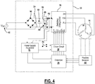
Figure 4 is a schematic circuit diagram of an example motor control system for the power tool; -
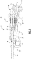
Figure 5 is a perspective view of the example embodiment of the power tool having a paddle trigger switch; -
Figs. 6 and7 depict inner perspective views of a cover including the paddle trigger switch attached thereto; and -
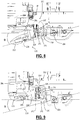
Figs. 8 and 9 depicts cross-sectional views of the power tool including the paddle switch and an associated actuation assembly. - Example embodiments will now be described more fully with reference to the accompanying drawings.
- Referring to
Figures 1 ,2A ,2B , and3 , apower tool 10 is shown. In this example embodiment, thepower tool 10 includes anelongated housing 12, a motor 16 (Figure 3 ), a module casing or power module support structure 18 (Figure 3 ), and a planar circuit board 20 (Figure 3 ). - The
housing 12 defines a cavity 21 (Figure 3 ) and includes amotor case 22 and ahandle portion 23. Themotor case 22 is positioned at one end 12-1 of thehousing 12 and includes agear case 24 and a slidingswitch 25. Thegear case 24 includes agearset 11, anoutput shaft 27, and a threadedopening 28. Thegearset 11 is positioned within thegear case 24 and is drivably coupled to themotor 16. Theoutput shaft 27 is drivably connected to thegearset 11 within thegear case 24 and extends perpendicular to the longitudinal axis of thehousing 12. Theoutput shaft 27 is also coupled to a grinding or a cutting disc (not shown) via a flange (not shown). The grinding disk may be removed and replaced with a new grinding disk. For example, a user of thepower tool 10 may replace the existing grinding disk with a new grinding disk after the existing disk wears out. Anadjustable guard 29 may cover at least a portion of the rotating disk to obstruct sparks and debris generated during operation of thepower tool 10. The threadedopening 28 allows for selectively attaching a side-handle (not shown) to enable two-handed operation. The slidingswitch 25 is positioned on a side of themotor case 22 and engages a power on/off switch 24 (described below) to allow for the user to turn thepower tool 10 ON and OFF. - The
handle portion 23 extends axially from themotor case 22 toward a second end 12-2 of thehousing 12 and includes afirst cover 23a and asecond cover 23b. The first and thesecond covers module casing 18 and theplanar circuit board 20 disposed within thecavity 21 of thehandle portion 23. Thesecond cover 23b includes asupport member 30 protruding outwardly therefrom and positioned at the second end 12-2 of thehousing 12. Thesupport member 30 includesopenings 31 extending therethrough to allow incoming air to enter thecavity 21. AnAC power cord 32 is attached to thehandle portion 23 at the second end 12-2 of thehousing 12 to supply electric power to thepower tool 10. - While the present description is provided with reference to a grinder, it is readily understood that the broader aspects of the present disclosure are applicable to other types of power tools, including but not limited to sander, drill, impact driver, tapper, fastener driver, and saw. For example, the
power tool 10 may include a chuck that is configured to receive a drill bit or a screw bit, thereby allowing thepower tool 10 to be used as a power drill or a power screw driver. -
Figure 4 depicts a schematic that illustrates an example of amotor drive circuit 33. Many components included in themotor drive circuit 33 may be integrated on theplanar circuit board 20 disposed entirely within thecavity 21 of thehandle portion 23. Themotor drive circuit 33 is comprised generally of acontroller 34, a switchingarrangement 36, adriver circuit 38, arectifier 40, aDC bus capacitor 42, apower supply 44, and anauxiliary switch path 46. Themotor drive circuit 33 may further include positionedsensors 48, such as Hall Effect sensors that are configured to detect rotational motion of themotor 16 and generate a signal indicative of the rotational motion. The signal may have a periodic waveform whose magnitude may vary in accordance with the rotational position of themotor 16. It should be noted, that other types of positional sensors may be alternatively utilized and should not be limited to Hall Effect sensors. - An
AC supply 52 delivers an alternating current to therectifier 40 through, for example, thepower cord 32. Therectifier 40 converts the alternating current into a direct current that is outputted to a DC bus 54 (i.e., power line/bus). The output of therectifier 40 may be pulsating DC signal and not a pure DC signal. - The
DC bus capacitor 42 is electrically connected in parallel with therectifier 40. The switchingarrangement 36 is electrically connected with theDC bus capacitor 42 and may receive the pure DC signal or the substantially pure DC signal from theDC bus capacitor 42 via theDC bus 54. The switchingarrangement 36 includes a plurality of motor switches that, when switched on, deliver the DC current to themotor 16 on phase voltage lines 55 (PV, PW, PU). The motor switches may be IGBTs or FETs, for example. The switchingarrangement 36 may be further defined as a three-phase inverter bridge although other arrangements are contemplated by this disclosure. - The
DC bus capacitor 42 may be a link capacitor having relatively small capacitance and does not act to smoothen the full-wave rectified AC voltage. TheDC bus capacitor 42 is a bypass capacitor that removes the high frequency noise from the bus voltage. - The
auxiliary switch path 46 is electrically coupled in parallel with therectifier 40 and thelink capacitor 42, and is electrically connected between therectifier 40 and the switchingarrangement 36. Theauxiliary switch path 46 includes anauxiliary capacitor 56 and aswitch 58 positioned in series with theauxiliary capacitor 56. - The
switch 58 may be a controlled switch, such as a MOSFET or an IGBT, in an embodiment. Theswitch 58 may be controlled by software programmed into thecontroller 34 or another programmable microcontroller. Alternatively, theswitch 58 may be controlled by hardware, such as aswitch control circuit 60, described in detail below. When theswitch 58 is closed, theauxiliary capacitor 56 is connected parallel to theDC bus capacitor 42. - The
driver circuit 38 interfaces with the motor switches of the switchingarrangement 36. Thedriver circuit 38 controls the state of the motor switches. In the example embodiment, thedriver circuit 38 is shown as being separate from the switchingarrangement 36. Alternatively, thedriver circuit 38 and the switchingarrangement 36 may be a single integrated circuit which may be commercially available from various manufacturers. For example, the switchingarrangement 36, which may include IGBTs, and thedriver circuit 38 may be a part of an integrated power module. - The
controller 34 interfaces with thedriver circuit 38 and may generate PWM signals to control themotor 16. In this embodiment, thecontroller 34 receives power from thepower supply regulator 44. In an alternate embodiment, thecontroller 34 may receive power directly from therectifier 40. - The
power supply regulator 44 is electrically connected in parallel with therectifier 40 and operates to power thedriver circuit 38 via a power on/offswitch 26. The power on/offswitch 26 is positioned between thepower supply regulator 44 and thedriver circuit 38. In an embodiment, the power on/offswitch 26 is an analog logic switch capable of carrying a voltage of up to 20V from thepower supply regulator 44 to thegate driver circuit 38. The power on/offswitch 26 may be a current-carrying power switch activated via a normally-open contact member. When the contact member is pressed down, the power on/off switch switches to the ON-position. - When the power on/off
switch 26 is switched to the ON-position, thedriver circuit 38 receives power from thepower supply regulator 44. When thedriver circuit 38 receives power, thedriver circuit 38 is able to control the state of the motor switches 55 and themotor 16 is on. - Conversely, when the power on/off
switch 26 is switched to the OFF-position, thedriver circuit 38 does not receive power from thepower supply regulator 44. When thedriver circuit 38 does not receive power, thedriver circuit 38 is not able to control the state of the motor switches 55 and the electric motor is off. - As illustrated, the power on/off
switch 26 is electrically connected between therectifier 40 and thedriver circuit 38. The power on/offswitch 26 is positioned such that the power from theAC power supply 52 does not pass through the power on/offswitch 26. Furthermore, the current being drawn by themotor 16 does not pass through the power on/offswitch 26. The current passing through the power on/offswitch 26 is the current being drawn by thedriver circuit 38 and the current being drawn by thedriver circuit 38 is lower than the current being drawn by theelectric motor 16. - The power on/off
switch 26 may be engaged via a slidingswitch 25 as shown inFig. 1 . The power on/offswitch 26 may alternatively be engaged via apaddle switch 200, as shown inFig. 5 and described below. - Patent No.
8,087,976 - The '976 patent also described an example of a conventional paddle switch. Generally speaking, a paddle switch includes a paddle trigger that pivots around a pivot post, and an arm that extends from the paddle switch across the pivot posts. The actuation of the paddle trigger causes the arm the make or break contact with the power on/off switch to turn the tool on or off.
- Such conventional sliding switches and paddle switch are suitable for engaging conventional on/off power switches that are disposed on the current path from the power supply. Such power switches tend to be relatively large, with a contact portion that has a travel distance of, for example, 4 to 8 mm. For example, the contact portion of on/off
switch 24 inFig. 5 of the '976 patent can turn on after theface 56 of the paddle switch travels 2-3 mm, but can absorb another 4 mm of travel distance byface 56. Such power switches provide some degree of flexibility for the travel distance of the slider button (for a sliding switch) or the paddle trigger (for a paddle switch). - According to an embodiment, as described above, the power on/off
switch 26 is an analog logic switch capable of carrying a voltage of up to 20V from thepower supply regulator 44 to thegate driver circuit 38. Thus, the power on/offswitch 26 may be much smaller in size than conventional high-current power switches, and as such, may be provided with a contact portion that can absorb a significantly smaller travel distance. In an embodiment, the contact portion of the power on/offswitch 26 may only have a total travel distance of less than 1 mm. - In an embodiment, where
power tool 10 is provided with a slidingswitch 25, as shown inFig. 1 , the slidingswitch 25 may be coupled to a link member (not shown) that is made of flexible material capable of absorbing extra the travel distance of the slidingswitch 25. Specifically, the contact face of the link member may be bendable to absorb the travel distance of the sliding switch of up to 10 mm. In this manner, if the contact face of the link member comes into contact with the contact portion of the on/offswitch 26 after, for example, 5mm of the slidingswitch 25 travel, and turns ON the on/off switch after, for example, 6mm of slidingswitch 25 travel, it bends to absorb the remaining travel distance of the slidingswitch 25 without damaging the on/offswitch 26. In this manner, the on/off switch turns ON approximately half-way within the travel distance of the slidingswitch 25. - In an embodiment, where
power tool 10 is provided with apaddle switch 200, as shown inFig. 5 , thepaddle switch 200 may be coupled to anactuation assembly 220, as described herein with reference toFigs. 6-9 . In an embodiment,paddle switch 200 may be incorporated intohandle cover 23b, as shown inFig. 5 and the perspective inner views ofFigs. 6 and7 .Figs. 8 and 9 depicts cross-sectional views of thepower tool 10 including thepaddle switch 200 and theactuation assembly 220. - In an embodiment, the
paddle switch 200 includes apaddle trigger 202 connected to thehandle cover 23b (or another part of the power tool housing 12) via apivot member 204. Thepaddle trigger 202 may include atrigger lock 206 pivotably extending from thepaddle trigger 202 and is spring-loaded to a locked position (Fig. 8 ), in which it prevents thepaddle trigger 202 from being pressed by the user from its default position. Thetrigger lock 206 is engaged by the user and rotated with respect to thepaddle trigger 202 to an unlocked position (Fig. 9 ) before thepaddle trigger 202 can be fully pressed by the user to activate thepower tool 10. When thepaddle trigger 202 is released, thetrigger lock 206 springs back into its locked position, and as it slides against thehandle cover 23b, it forces thepaddle trigger 202 away from thehandle cover 23b to its default position. - In an embodiment, the
actuation assembly 220 includes aswitch contact lever 222 arranged to engage acontact tip 26a of the on/offswitch 26. Theswitch contact lever 222 is positioned between thepaddle trigger 202 and the on/offswitch 26. A biasingmember 224, such as a compression spring, is disposed between thepaddle trigger 202 and theswitch contact lever 222.Switch contact lever 222 is rotatable around apivot member 226. In an embodiment,pivot member 226 pivotably connects theswitch contact lever 222 to aninner body portion 208 of thepaddle switch 200 that extends into thecover 23b from thepaddle trigger 202. Alternatively, thepivot member 226 may pivotably connect theswitch contact lever 222 to an inner wall of thehandle cover 23b or another part of thepower tool housing 12. In an embodiment thepivot member 226 may be the same (i.e., along the same axis) as thepivot member 204. Alternatively,pivot members - In an embodiment, the
actuation assembly 220 includes aspring post 210 disposed on an inner face of thepaddle trigger 202 within theinner body portion 208. Theswitch contact lever 222 similarly includes aspring post 228 facingspring post 210 of theactuation assembly 200. The biasingmember 224 is disposed around the spring posts 210 and 228 so as to biasedly locate theswitch contact lever 222 at an angular distance with respect to thepaddle trigger 202. Disposition of the biasingmember 224 between thepaddle trigger 202 and theswitch contact lever 222 allows theswitch contact lever 222 to move with the actuation of thepaddle trigger 202 until theswitch contact lever 222 comes into contact with thecontact tip 26a of on/offswitch 26 and turns on the on/offswitch 26, without damaging the on/offswitch 26 with further travel of thepaddle trigger 202. This is discussed below in detail. - In an embodiment, the
actuation assembly 220 also includes apaddle force lever 240 disposed adjacent theswitch contact lever 222. Thepaddle force lever 240 may be coupled toinner body portion 208 of thepaddle switch 200 viapivot member 226. Alternatively, paddleforce lever 240 may be coupled to thepaddle switch 220 via a separate pivot member. Thepaddle force lever 240 is spring-loaded with respect to thepaddle trigger 202 via a biasingmember 242. Atip 244 of thepaddle force lever 240 engages a portion of the housing 12 (e.g., an outer wall of the motor case 22), exerting a biasing force on thepaddle trigger 202 away from thehousing 12 to return thepaddle switch 200 to its default position when it is released by the user. - In an embodiment, extending from the
switch contact lever 222, opposite thepivot member 226, is disposed aleg 230 extending downwardly towards thepaddle switch 200. Thepaddle switch 200 includes acorresponding engagement post 212 projecting from an inner face of thepaddle trigger 202 adjacent thespring post 210 proximate theleg 230. When thepaddle switch 200 is released, theengagement post 212 engages theleg 230 so as to rotate theswitch contact lever 222 away from the on/offswitch 26. Theengagement post 212 does not engage theleg 230 when thepaddle switch 200 is pressed. - During operation, when the
paddle switch 200 is pressed by the user, thepaddle trigger 202 is rotated about thepivot member 204. The total angular travel range θ of thepaddle trigger 202 may be, in an embodiment, approximately 10-20 degrees, and in an example, approximately 15 degrees. Within a first angular travel range of the paddle trigger 202 (e.g., 0 to 6 degrees), theswitch contact lever 222 moves freely (at approximately the same angular travel distance) with thepaddle trigger 202 until it comes into contact with the on/offswitch 26. Within a second angular travel range of the paddle trigger 202 (e.g., between 6 to 10 degrees), theswitch contact lever 222 engages and presses on thecontact tip 26a of the on/offswitch 26 to turn it on. The compression force of the biasingmember 224 is sufficient to allow theswitch contact lever 222 to actuate thecontact tip 26a of the on/offswitch 26, but may absorb some of the impact. In an embodiment, the angular travel distance of theswitch contact lever 222 is smaller than the angular travel distance of thepaddle trigger 202 within the second angular travel range. Thereafter, within a third angular travel range of the paddle trigger 202 (e.g., 10 to 15 degrees), theswitch contact lever 222 remains substantially in place in contact with the on/offswitch 26 while the biasingmember 224 absorbs the over-travel distance of thepaddle trigger 202. The biasing fore of the spring is overcome by the on/offswitch 26 within the third angular travel range so theswitch contact lever 222 does not damage the on/offswitch 26. With this arrangement, the on/offswitch 26 turns on within approximately 40-70% of the travel distance of thepaddle trigger 202 and the biasingmember 224 absorbs the remaining travel distance of thepaddle trigger 202 to prevent damage to the on/offswitch 26. - The foregoing description of the embodiments has been provided for purposes of illustration and description. It is not intended to be exhaustive or to limit the disclosure. Individual elements or features of a particular embodiment are generally not limited to that particular embodiment, but, where applicable, are interchangeable and can be used in a selected embodiment, even if not specifically shown or described. The same may also be varied in many ways. Such variations are not to be regarded as a departure from the disclosure, and all such modifications are intended to be included within the scope of the disclosure.
- The terminology used herein is for the purpose of describing particular example embodiments only and is not intended to be limiting. As used herein, the singular forms "a," "an," and "the" may be intended to include the plural forms as well, unless the context clearly indicates otherwise. The terms "comprises," "comprising," "including," and "having," are inclusive and therefore specify the presence of stated features, integers, steps, operations, elements, and/or components, but do not preclude the presence or addition of one or more other features, integers, steps, operations, elements, components, and/or groups thereof. The method steps, processes, and operations described herein are not to be construed as necessarily requiring their performance in the particular order discussed or illustrated, unless specifically identified as an order of performance. It is also to be understood that additional or alternative steps may be employed.
- When an element or layer is referred to as being "on," "engaged to," "connected to," or "coupled to" another element or layer, it may be directly on, engaged, connected or coupled to the other element or layer, or intervening elements or layers may be present. In contrast, when an element is referred to as being "directly on," "directly engaged to," "directly connected to," or "directly coupled to" another element or layer, there may be no intervening elements or layers present. Other words used to describe the relationship between elements should be interpreted in a like fashion (e.g., "between" versus "directly between," "adjacent" versus "directly adjacent," etc.). As used herein, the term "and/or" includes any and all combinations of one or more of the associated listed items.
- Although the terms first, second, third, etc. may be used herein to describe various elements, components, regions, layers and/or sections, these elements, components, regions, layers and/or sections should not be limited by these terms. These terms may be only used to distinguish one element, component, region, layer or section from another region, layer or section. Terms such as "first," "second," and other numerical terms when used herein do not imply a sequence or order unless clearly indicated by the context. Thus, a first element, component, region, layer or section discussed below could be termed a second element, component, region, layer or section without departing from the teachings of the example embodiments.
- Spatially relative terms, such as "inner," "outer," "beneath," "below," "lower," "above," "upper," and the like, may be used herein for ease of description to describe one element or feature's relationship to another element(s) or feature(s) as illustrated in the figures. Spatially relative terms may be intended to encompass different orientations of the device in use or operation in addition to the orientation depicted in the figures. For example, if the device in the figures is turned over, elements described as "below" or "beneath" other elements or features would then be oriented "above" the other elements or features. Thus, the example term "below" can encompass both an orientation of above and below. The device may be otherwise oriented (rotated 90 degrees or at other orientations) and the spatially relative descriptors used herein interpreted accordingly.
Claims (15)
- A power tool comprising:a housing;a motor disposed within the housing;an on/off switch having a contact tip disposed within the housing for activating the motor;a paddle switch coupled to the housing via a pivot member and having a paddle trigger engageable by a user;a switch contact lever disposed in selectable engagement with the contact tip of the on/off switch to activate or deactivate the on/off switch; anda biasing member disposed between the switch contact lever and the paddle switch to absorb a travel distance of the paddle trigger with respect to the switch contact lever.
- The power tool of claim 1, wherein the switch contact lever is coupled to the paddle switch via a second pivot member.
- The power tool of claim 2, wherein the paddle switch comprises an inner body extending into the housing from the paddle trigger, and the second pivot member is coupled to the inner body.
- The power tool of claim 1, wherein the switch contact lever is disposed between the paddle switch and the on/off switch.
- The power tool of claim 1, wherein the switch contact lever includes a first spring post, the paddle trigger includes a second spring post, and ends of the biasing member are disposed around the first spring post and the second spring post.
- The power tool of claim 1, wherein the spring post is disposed to support the switch contact lever at an angular distance with respect to the paddle trigger in a default position of the paddle trigger.
- The power tool of claim 1, wherein, within a first angular travel range of the paddle trigger, the switch contact lever moves with the paddle trigger at approximately the same angular travel distance.
- The power tool of claim 7, wherein: within a second angular travel range of the paddle trigger, the switch contact lever engages and presses on the contact tip of the on/off switch to activate the on/off switch, and/or within a third angular travel range of the paddle trigger, the switch contact lever remains substantially in place in engagement with the contact tip of the on/off switch.
- The power tool of claim 8, wherein the angular travel distance of the switch contact lever is smaller than the angular travel distance of the paddle trigger within the second angular travel range of the paddle trigger.
- The power tool of claim 8, wherein the first angular travel range of the paddle trigger is approximately 30-40% of the total angular travel range of the paddle trigger, the second angular travel range of the paddle trigger is approximately 20-30% of the total angular travel range of the paddle trigger, and the third angular travel range of the paddle trigger is approximately 30-40% of the total angular travel range of the paddle trigger.
- The power tool of claim 1, further comprising a paddle force lever disposed between the paddle switch and a portion of the housing to apply a biasing force on the paddle switch away from the housing.
- The power tool of claim 11, wherein the paddle force lever is coupled to the paddle switch via a second pivot member.
- The power tool of claim 2, further comprising a leg extending from the switch contact lever opposite the second pivot member, and the paddle switch engages the leg to rotate the switch contact lever away from the on/off switch when the paddle trigger is released.
- The power tool of claim 13, wherein the paddle switch comprises an engagement post projecting from an inner face of the paddle trigger that engages the leg when the paddle trigger is released.
- The power tool of claim 1, further comprising:a switching arrangement between a power supply and the motor;a controller configured to control a switching operation of the switching arrangement circuit to control an operation of the motor;a driver circuit disposed between the controller and the switching arrangement to provide voltage signals for controlling the switching operation of the switching arrangement; anda power supply regulator for supplying a voltage input to at least one of the driver circuit or the controller.
Applications Claiming Priority (1)
| Application Number | Priority Date | Filing Date | Title |
|---|---|---|---|
| US15/622,808 US10818450B2 (en) | 2017-06-14 | 2017-06-14 | Paddle switch |
Publications (2)
| Publication Number | Publication Date |
|---|---|
| EP3415280A1 true EP3415280A1 (en) | 2018-12-19 |
| EP3415280B1 EP3415280B1 (en) | 2021-12-01 |
Family
ID=59152710
Family Applications (1)
| Application Number | Title | Priority Date | Filing Date |
|---|---|---|---|
| EP17177438.3A Active EP3415280B1 (en) | 2017-06-14 | 2017-06-22 | Power tool with a paddle switch |
Country Status (2)
| Country | Link |
|---|---|
| US (1) | US10818450B2 (en) |
| EP (1) | EP3415280B1 (en) |
Cited By (2)
| Publication number | Priority date | Publication date | Assignee | Title |
|---|---|---|---|---|
| EP3678154A1 (en) * | 2019-01-03 | 2020-07-08 | Defond Components Limited | A locking system for use with a trigger assembly of an electrical device |
| EP4008492A1 (en) * | 2020-12-04 | 2022-06-08 | Hilti Aktiengesellschaft | Handle for machine tool, machine tool and method for turning on, turning off and locking the same |
Families Citing this family (4)
| Publication number | Priority date | Publication date | Assignee | Title |
|---|---|---|---|---|
| DE102016125435A1 (en) * | 2016-12-22 | 2018-06-28 | C. & E. Fein Gmbh | Hand tool |
| DE102019216865A1 (en) * | 2019-10-31 | 2021-05-06 | Robert Bosch Gmbh | Hand machine tool |
| CN112038137A (en) * | 2020-09-23 | 2020-12-04 | 格力博(江苏)股份有限公司 | Switch assembly and electric tool |
| EP4223457A1 (en) * | 2022-02-02 | 2023-08-09 | C. & E. Fein GmbH | Housing for an electric machine tool |
Citations (4)
| Publication number | Priority date | Publication date | Assignee | Title |
|---|---|---|---|---|
| DE2944750A1 (en) * | 1979-11-06 | 1981-05-21 | Metabowerke GmbH & Co, 7440 Nürtingen | Double-action safety switch for power tools - has deadman release switch and excess pressure switch |
| US4879438A (en) * | 1988-08-01 | 1989-11-07 | Ryobi Motor Products Corp. | Lock-on/lock-off switch for power tool |
| US5428197A (en) * | 1993-06-01 | 1995-06-27 | Ryobi Motor Products Corp. | Electric tool actuator switch |
| US8087976B2 (en) | 2005-05-13 | 2012-01-03 | Black & Decker Inc. | Trigger assembly for angle grinder |
Family Cites Families (383)
| Publication number | Priority date | Publication date | Assignee | Title |
|---|---|---|---|---|
| DE178451C (en) | ||||
| DE155280C (en) | ||||
| DE341238C (en) | ||||
| DE123407C (en) | ||||
| DE1073606B (en) | 1960-01-21 | Wilhelm Bender, CaIw (WÜrtt.) | Electric hand tools with cooling air brought in from another point | |
| DE131551C (en) | ||||
| DE118339C (en) | ||||
| US394417A (en) | 1888-12-11 | Poele | ||
| DE311993C (en) | ||||
| DE225343C (en) | ||||
| DE122029C (en) | ||||
| US731740A (en) | 1902-03-24 | 1903-06-23 | Gen Electric | Commutator-brush. |
| DE429619C (en) | 1920-08-15 | 1926-05-31 | Siemens Schuckertwerke G M B H | Brush holder with swing arm under spring force |
| DE482136C (en) | 1927-12-17 | 1929-09-07 | Sachsenwerk Licht & Kraft Ag | Cooling air cleaning device for electrical machines with draft ventilation, in which the cooling air is sucked into the machine interior by means of a fan |
| US1971790A (en) | 1932-06-22 | 1934-08-28 | Arthur W Mall | Portable power tool |
| US2079143A (en) | 1935-01-19 | 1937-05-04 | Albertson & Co Inc | Sanding machine |
| US2201420A (en) | 1937-09-13 | 1940-05-21 | Wodack Electric Tool Corp | Abrading machine |
| US2192845A (en) | 1937-09-28 | 1940-03-05 | Gen Electric | Power unit |
| DE736475C (en) | 1940-06-20 | 1943-06-18 | Graetz Ag | Arrangement of a shaft bearing in the narrowed housing of electric motors |
| US2348341A (en) | 1940-07-29 | 1944-05-09 | Chicago Electric Mfg Co | Motor |
| DE881831C (en) | 1942-09-01 | 1953-07-02 | Siemens Ag | Brush holder for commutators or electrical slip ring arrangements |
| DE923803C (en) | 1952-10-15 | 1955-02-21 | Ringsdorff Werke Gmbh | Brush holder with brush |
| US2987636A (en) | 1953-07-09 | 1961-06-06 | Sunbeam Corp | Electric mixer |
| DE944976C (en) | 1955-02-18 | 1956-06-28 | Joachim Csaki Dipl Ing | Filter for air-cooled machines, especially electric hand tool machines |
| DE1007870B (en) | 1956-01-30 | 1957-05-09 | Licentia Gmbh | Power tool driven by a closed, jacket-cooled commutator motor with external ventilation |
| DE1006950B (en) | 1956-02-06 | 1957-04-25 | Alb Urbahn & Comp Werkzeug Und | Electric tool driven by a three-phase motor |
| DE1030443B (en) | 1956-05-07 | 1958-05-22 | Wilhelm Bender | Electric motor with dust filter device |
| US2905266A (en) | 1957-08-16 | 1959-09-22 | Torit Mfg Company | Separators |
| DE1046169B (en) | 1957-09-12 | 1958-12-11 | Wilhelm Bender | Electric motor with dust filter device |
| US3077340A (en) | 1958-08-25 | 1963-02-12 | Sunbeam Corp | Electric mixer |
| DE1110740B (en) | 1959-11-06 | 1961-07-13 | Bosch Gmbh Robert | Double-insulated electric hand tool with end shield and gear housing made of metal |
| DE1843271U (en) | 1961-03-04 | 1961-12-14 | Schmid & Wezel | INTENSIVE VENTILATION ESPECIALLY FOR THREE-PHASE MANUAL MOTORS. |
| CH398768A (en) | 1961-11-13 | 1966-03-15 | Heemaf N V Aktiengesellschaft | Electric machine with air cooling and a dust collector |
| DE1154863B (en) | 1962-07-17 | 1963-09-26 | Wilhelm Bender | Large surface dust filter extending over the entire outer circumference of an electric motor, especially for hand-held machine tools |
| CH406888A (en) | 1962-11-19 | 1966-01-31 | Suhner Willy | Electric angle hand grinder with ventilation |
| US3305281A (en) | 1963-07-19 | 1967-02-21 | Champ Items Inc | Idler arm repair kit |
| NL133349C (en) | 1963-12-30 | |||
| US3325948A (en) | 1964-03-11 | 1967-06-20 | Skil Corp | Belt sander |
| US3266535A (en) | 1964-06-01 | 1966-08-16 | Singer Co | Safety blade clamping means for portable power saws |
| CH456301A (en) | 1965-11-19 | 1968-07-15 | Mets Owerke Kg Closs Rauch & S | Electrically powered drill |
| US3474575A (en) | 1967-01-18 | 1969-10-28 | Black & Decker Mfg Co | Housing and handle construction for a belt-type sander |
| DE1763401A1 (en) | 1968-05-21 | 1971-08-05 | Schunk & Ebe Gmbh | Brush holders for electrical machines |
| US3535829A (en) | 1968-05-21 | 1970-10-27 | Singer Co | Belt cleaners for belt sanders |
| IL32256A (en) | 1968-06-27 | 1972-10-29 | Scm Corp | Compositions containing a beta-di-lower alkylamino lower alkylene thioether or a salt thereof,and their use as herbicides |
| GB1165526A (en) | 1968-06-28 | 1969-10-01 | Standard Telephones Cables Ltd | Improvements in or relating to Automatic Telephone Exchanges |
| US3530337A (en) | 1968-11-06 | 1970-09-22 | Thomas Moore | Electrical motor overload indicator and voltage cutout device |
| DE1952876A1 (en) | 1969-10-21 | 1971-03-18 | Ymos Metallwerke Wolf & Becker | Motor vehicle door lock |
| ZA703543B (en) | 1969-11-14 | 1971-01-27 | Magneti Marelli Spa | A frame for electric low capacity motors,provided with covers retained by small,deformed wings |
| US3797336A (en) | 1970-03-02 | 1974-03-19 | W Howe | Quick connect nut |
| DE7010521U (en) | 1970-03-21 | 1971-08-26 | Bosch Gmbh Robert | SHUT-OFF CARBON BRUSH. |
| DE2039793A1 (en) | 1970-08-04 | 1972-02-10 | Danow George Prof Dipl Ing | Brush apparatus with box-less guide and self-adjustable brush |
| DE7031833U (en) | 1970-08-26 | 1971-04-15 | Heid & Co Gmbh Kg Kohlebuerste | MOUNTING OF CARBON BRUSHES, IN PARTICULAR FOR SLIP RINGS |
| DE2147927B2 (en) | 1971-09-25 | 1975-02-06 | Licentia Patent-Verwaltungs-Gmbh, 6000 Frankfurt | Plastics coil holder for salient pole motors field-coil heads - has shoulders holding heads and hollow split legs sealing coil slots |
| DE2156770C3 (en) | 1971-11-16 | 1974-06-20 | Hermann 7031 Maichingen Hefner | Device for the releasable fastening of a grinding wheel or the like on a drive spindle |
| US3731556A (en) | 1971-11-17 | 1973-05-08 | Cincinnati Milacron Inc | Dynamic balancing apparatus |
| DE2158598B2 (en) | 1971-11-26 | 1974-05-09 | Metabowerke Kg, Closs, Rauch & Schnizler, 7440 Nuertingen | Lubricating device for gears with operation in all positions |
| US3824745A (en) | 1972-08-21 | 1974-07-23 | A Hutchins | Suction system for abrading tool |
| US3760570A (en) | 1972-09-05 | 1973-09-25 | Black & Decker Mfg Co | Centrifugally responsive brake for rotary tool |
| DE2316323C3 (en) | 1973-04-02 | 1975-12-04 | Hermann 8183 St Quirin Schock | Sealing pipe penetration on a pipe to be laid in the ground |
| US3854020A (en) | 1973-06-29 | 1974-12-10 | Black & Decker Mfg Co | Trigger mechanism for hand-operated power device including stationary locking device which provides lock-off and lock-on operation |
| US3847233A (en) | 1973-06-29 | 1974-11-12 | Black & Decker Mfg Co | Trigger mechanism for hand-operated power device providing automatic lock-off and manual lock-on operation |
| US3873796A (en) | 1973-07-06 | 1975-03-25 | Black & Decker Mfg Co | Trigger mechanism for hand-operated power device including independently operable locking devices providing automatic lock off and manual lock-on operation |
| US3872951A (en) | 1973-11-06 | 1975-03-25 | Black & Decker Mfg Co | Spindle locking mechanism for rotary power device |
| US3961433A (en) | 1974-06-21 | 1976-06-08 | The Raymond Lee Organization Inc. | Picture poster viewer |
| US3899852A (en) | 1974-08-23 | 1975-08-19 | Singer Co | Spindle drive assembly for a surface-treating machine |
| US4007401A (en) | 1974-09-09 | 1977-02-08 | Westinghouse Electric Corporation | Current sensitive circuit protection system |
| US4020359A (en) | 1975-03-24 | 1977-04-26 | Davy Powergas Limited | Electrical control system |
| US3999176A (en) | 1975-04-07 | 1976-12-21 | Westinghouse Electric Corporation | Indicator light circuit providing normal and emergency indication |
| GB1519421A (en) | 1976-02-18 | 1978-07-26 | Trico Folberth Ltd | Brush mountings |
| DE2626003A1 (en) | 1976-06-10 | 1977-12-22 | Schulte Elektrotech | Multipole pushbutton switch with thermal overcurrent trip - has contacts connected to protective device and slide coupled to holding unit |
| CH607574A5 (en) | 1976-08-13 | 1978-08-31 | Wachendorf L & Co Ag | Brush holder for electrical machines |
| NL7711072A (en) | 1976-10-23 | 1978-04-25 | Textima Ag | PRESS, ESPECIALLY FOR METALWORKING. |
| DE7802306U1 (en) | 1977-02-10 | 1978-05-03 | Valentini, Guido, Vermezzo, Mailand (Italien) | TRANSPORTABLE, CIRCULAR, ELECTRIC GRINDING MACHINE |
| DE7709148U1 (en) | 1977-03-24 | 1977-07-14 | Christian Geyer Gmbh & Co, 8500 Nuernberg | Spacers for conductors in roof post tubes |
| DE7728401U1 (en) | 1977-09-14 | 1979-07-19 | Marton, Miksa, Windsor, Ontario (Kanada) | DISC HAND GRINDING MACHINE |
| DE2850120A1 (en) | 1977-11-21 | 1979-05-23 | Black & Decker Mfg Co | SWITCH OPERATING DEVICE |
| US4145848A (en) | 1978-01-24 | 1979-03-27 | Hutchins Manufacturing Co. | Rotary abrading tool |
| DE2813956B1 (en) | 1978-03-31 | 1979-04-26 | Siemens Ag | Collector motor with a plastic brush support plate that can be fixed in an opening in the motor housing |
| US4232414A (en) | 1978-07-10 | 1980-11-11 | Cooper Industries, Inc. | Free-wheeling overspeed grinder device |
| US4186288A (en) | 1978-09-01 | 1980-01-29 | Stackpole Components Company | Slide switch |
| JPS5928151B2 (en) | 1978-11-04 | 1984-07-11 | ファナック株式会社 | Protection method for motor drive inverter circuit |
| US4205732A (en) | 1979-03-07 | 1980-06-03 | Ingersoll-Rand Company | Muffler for portable pneumatic tool |
| DE2919669A1 (en) | 1979-05-16 | 1980-11-20 | Licentia Gmbh | Angle grinder clamping nut - has three or more recesses for spanner lugs on concentric circle |
| US4250587A (en) | 1979-07-02 | 1981-02-17 | Beck John W Jr | Scrubbing device |
| DE2927331A1 (en) | 1979-07-06 | 1981-02-05 | Bosch Gmbh Robert | BRUSH HOLDER WITH BRUSH LIFTING DEVICE |
| DE3001907C2 (en) | 1980-01-19 | 1982-11-18 | Licentia Patent-Verwaltungs-Gmbh, 6000 Frankfurt | Device for locking the drive spindle of angle grinders and similar hand-held power tools |
| DE3004316C2 (en) | 1980-02-06 | 1983-12-29 | Skf Kugellagerfabriken Gmbh, 8720 Schweinfurt | Storage of a shaft of a machine element |
| US4278371A (en) | 1980-02-29 | 1981-07-14 | Milwaukee Electric Tool Corporation | Safety interlock for electro-magnetic drill stand |
| US4295295A (en) | 1980-03-17 | 1981-10-20 | Tyco Industries, Inc. | Pick-up shoe and motor contact assembly for toy vehicle |
| NL8003635A (en) | 1980-06-24 | 1982-01-18 | Noord Ver Metaal | Hand-held device for updating the claws of one or two-toed animals, such as cows. |
| DE3023691A1 (en) | 1980-06-25 | 1982-01-21 | Robert Bosch Gmbh, 7000 Stuttgart | SWITCH WITH A CONTROL DEVICE, IN PARTICULAR ON A HAND MACHINE TOOL |
| DE3023803A1 (en) | 1980-06-25 | 1982-01-21 | Siemens AG, 1000 Berlin und 8000 München | COLLECTOR MOTOR |
| DE8016761U1 (en) | 1980-06-25 | 1982-06-24 | Robert Bosch Gmbh, 7000 Stuttgart | Switch with an operating means, in particular on a hand machine tool |
| WO1982000353A1 (en) | 1980-07-21 | 1982-02-04 | Ab Sandvik | Balancing means for a rotating tool |
| US4334332A (en) | 1980-08-06 | 1982-06-15 | Downs Edgar S | Motor-driven cap-gripper and can-opener |
| DE3031915A1 (en) | 1980-08-23 | 1982-04-08 | Robert Bosch Gmbh, 7000 Stuttgart | Wear detecting appts. - senses wear of carbon brushes in motor by using contacts or by visual inspection |
| US4343502A (en) | 1980-10-09 | 1982-08-10 | Ingersoll-Rand Company | Doorknob construction |
| US4434586A (en) | 1980-12-03 | 1984-03-06 | Robert Bosch Gmbh | Machine tool, especially a hand-held power tool with a turnable clamping element for clamping a tool on the tool spindle |
| DE3110912A1 (en) | 1981-03-20 | 1982-09-30 | Licentia Patent-Verwaltungs-Gmbh, 6000 Frankfurt | Clamping device for the grinding wheel of an angle grinder |
| JPS57171601U (en) | 1981-04-24 | 1982-10-28 | ||
| DE3118831A1 (en) | 1981-05-12 | 1983-01-27 | Hans 8801 Schillingsfürst Heinlein | Filter arrangement |
| US4400995A (en) | 1981-09-23 | 1983-08-30 | Milwaukee Electric Tool Corporation | Spindle lock with impacting capability |
| CH653280A5 (en) | 1981-10-08 | 1985-12-31 | Ceka Elektrowerkzeuge Ag & Co | SWITCHING DEVICE FOR THE DRIVE MOTOR OF AN ELECTRIC TOOL. |
| US4536670A (en) | 1981-12-14 | 1985-08-20 | Morganite Incorporated | Electrical brushes with wear sensors |
| NL8200652A (en) | 1982-02-18 | 1983-09-16 | Skil Nederland Nv | ELECTRIC MOTOR WITH IMPROVED BRUSH CONSTRUCTION. |
| DE8214078U1 (en) | 1982-05-14 | 1982-10-07 | Uhde Gmbh, 4600 Dortmund | SPACER FOR PIPELINES |
| JPS5923125U (en) | 1982-08-03 | 1984-02-13 | アルプス電気株式会社 | slide switch |
| US4476602A (en) | 1982-08-13 | 1984-10-16 | Black & Decker, Inc. | Portable electric scrubber |
| JPS5930653U (en) | 1982-08-20 | 1984-02-25 | マブチモ−タ−株式会社 | Small motor brush device |
| JPS5937859U (en) | 1982-08-30 | 1984-03-09 | マブチモ−タ−株式会社 | brush device |
| JPS5949380A (en) | 1982-09-14 | 1984-03-21 | Sanyo Electric Co Ltd | Pumping device |
| DE3317425A1 (en) | 1983-05-13 | 1984-08-09 | Daimler-Benz Ag, 7000 Stuttgart | Holder for a cutting tool on a robot head |
| US4467896A (en) | 1983-06-17 | 1984-08-28 | Black & Decker Inc. | Locking mechanism for a rotary power machine |
| DE8317913U1 (en) | 1983-06-21 | 1984-11-29 | Robert Bosch Gmbh, 7000 Stuttgart | DEVICE FOR LOCKING THE GRINDING SPINDLE OF ANGLE GRINDERS |
| DE3328955A1 (en) | 1983-08-11 | 1985-02-21 | Robert Bosch Gmbh, 7000 Stuttgart | ANGLE GRINDERS WITH A SAFETY CLUTCH |
| DE3341874C1 (en) | 1983-09-08 | 1984-07-19 | Schulte-Elektrotechnik GmbH & Co KG, 5880 Lüdenscheid | Switch arrangement having zero-voltage tripping |
| DE8327966U1 (en) | 1983-09-29 | 1984-01-26 | Karl M. Reich Maschinenfabrik GmbH, 7440 Nürtingen | SWITCHES FOR ELECTRIC TOOLS |
| JPS60152247A (en) | 1984-01-20 | 1985-08-10 | Toshiba Corp | Variable speed motor with inverter |
| EP0171446B1 (en) | 1984-08-13 | 1987-11-25 | Siemens Aktiengesellschaft | Thermic overload protection for a commutator or slipring-motor |
| WO1986001936A1 (en) | 1984-09-11 | 1986-03-27 | Heinrich Kopp Gmbh & Co. Kg | Variable switch-box for a motor (protection) switch and under-voltage trigger for incorporation in electrical tools etc. |
| DE8427601U1 (en) | 1984-09-19 | 1985-05-30 | Siemens AG, 1000 Berlin und 8000 München | HAMMER BRUSH HOLDER SYSTEM FOR A COMMUTATOR MOTOR |
| US4550277A (en) | 1984-09-24 | 1985-10-29 | Black & Decker Inc. | Overload detection and warning system for electric motors in power tools and the like |
| DE3501947A1 (en) | 1985-01-22 | 1986-07-24 | Apag Elektronik AG, Dübendorf, Zürich | Electric tool, especially an angle grinder |
| DE8504518U1 (en) | 1985-02-18 | 1985-05-15 | Papst-Motoren GmbH & Co KG, 7742 St Georgen | DEVICE FOR STRESS-RELEASED HOUSING OF THE STRAND CONNECTIONS IN SMALL ELECTRIC MOTORS |
| US4604538A (en) | 1985-02-19 | 1986-08-05 | General Motors Corporation | Air cooling for diode-rectified alternating current generators |
| US4770316A (en) | 1985-02-25 | 1988-09-13 | Black & Decker Inc. | Power device housing with lubricant anti-wicking facility |
| DE3512365A1 (en) | 1985-04-04 | 1986-10-16 | C. & E. Fein Gmbh & Co, 7000 Stuttgart | Hand-held electric tool having a braking device |
| DE3531309A1 (en) | 1985-09-02 | 1987-03-05 | Siemens Ag | Brush arrangement for commutator motors |
| DE8525046U1 (en) | 1985-09-02 | 1986-06-26 | Siemens AG, 1000 Berlin und 8000 München | Brush arrangement for commutator motors |
| JPH0323824Y2 (en) | 1985-12-09 | 1991-05-23 | ||
| DE3546394A1 (en) | 1985-12-31 | 1987-07-02 | Metabowerke Kg | Enclosed-ventilated electric motor |
| DE8601684U1 (en) | 1986-01-23 | 1987-05-21 | Siemens Ag, 1000 Berlin Und 8000 Muenchen, De | |
| DE3607377A1 (en) | 1986-03-06 | 1987-09-10 | Metabowerke Kg | ELECTRICALLY DRIVEN GRINDERS |
| CH673356A5 (en) | 1986-04-14 | 1990-02-28 | Portescap | |
| DE8705640U1 (en) | 1986-06-27 | 1987-10-29 | Schulte-Elektrotechnik Gmbh & Co Kg, 5880 Luedenscheid, De | |
| IT8622437V0 (en) | 1986-07-02 | 1986-07-02 | Valentini Guido | ELECTRIC MANUAL TOOL WITH MOTOR AND DUST DISCHARGE PIPE INCLUDED IN THE HANDLE. |
| DE3623555A1 (en) | 1986-07-12 | 1988-02-04 | Fein C & E | FASTENING DEVICE FOR DISC-SHAPED TOOLS ON THE TOOL SPINDLE OF A PORTABLE ELECTRIC TOOL MACHINE |
| DE3638952A1 (en) | 1986-11-14 | 1988-05-26 | Marquardt Gmbh | Electrical switch |
| DE8632779U1 (en) | 1986-12-06 | 1987-02-05 | Metabowerke Gmbh & Co, 7440 Nuertingen, De | |
| US4765099A (en) | 1986-12-11 | 1988-08-23 | Tanner John G | Sanding and dust collecting apparatus |
| DE3643067A1 (en) | 1986-12-17 | 1988-06-23 | Bosch Gmbh Robert | TENSIONING DEVICE FOR AXIAL CLAMPING OF A TOOL, IN PARTICULAR A DISC |
| DE3644441A1 (en) | 1986-12-24 | 1988-07-07 | Bosch Gmbh Robert | TENSIONING DEVICE FOR DETACHABLE FASTENING OF A TOOL, IN PARTICULAR A DISC |
| DE3700968A1 (en) | 1987-01-15 | 1988-08-04 | Bosch Gmbh Robert | TENSIONING DEVICE FOR AXIAL CLAMPING OF A TOOL, IN PARTICULAR A DISC |
| US4742257A (en) | 1987-01-29 | 1988-05-03 | General Motors Corporation | Totally enclosed fan cooled induction motor with improved cooling |
| US5100275A (en) | 1987-05-20 | 1992-03-31 | Schirrmacher Wendell E | Quick locking fasteners |
| DE3718891A1 (en) | 1987-06-05 | 1988-12-22 | Bayer Ag | MIXTURES OF POLYARYL SULFIDES AND POLYESTERS AND THEIR USE |
| DE3722629C2 (en) | 1987-07-09 | 1995-01-19 | Metabowerke Kg | Power tool with braking device |
| GB2207296A (en) | 1987-07-20 | 1989-01-25 | Johnson Electric Ind Mfg | Brush gear for an electric motor |
| DE3724747A1 (en) | 1987-07-25 | 1989-02-02 | Fein C & E | GRINDING DEVICE WITH DUST EXTRACTION DEVICE |
| DE3736535A1 (en) | 1987-10-28 | 1989-05-18 | Hoffmann Elektrokohle | GRINDING CONTACT ARRANGEMENT, ESPECIALLY FOR A CARBON BRUSH |
| DE3741484C1 (en) | 1987-12-08 | 1989-08-24 | Fein C & E | Hand machine tool with automatic locking of the work spindle |
| DE3741536A1 (en) | 1987-12-08 | 1989-06-22 | Erhard Pauls | Brake device for braking rotating machine elements, such as the rotor of a manual angle grinder |
| DE3809930A1 (en) | 1988-03-24 | 1989-10-05 | Bosch Gmbh Robert | Eccentric grinder |
| GB8812292D0 (en) | 1988-05-24 | 1988-06-29 | Black & Decker Inc | Improvements in/relating to power tools |
| JPH0217961A (en) | 1988-07-06 | 1990-01-22 | Ig Tech Res Inc | Coating device |
| DE3841181A1 (en) | 1988-12-07 | 1990-06-13 | Bosch Gmbh Robert | HAND MACHINE TOOL WITH A MULTI-PIECE MANUAL QUICK-RELEASE DEVICE |
| DE3828954A1 (en) | 1988-08-26 | 1990-03-08 | Licentia Gmbh | Device for the stationary braking of an electric power tool fitted with an angular gear |
| DE3844617A1 (en) | 1988-08-26 | 1990-03-22 | Licentia Gmbh | Power tool with a combined device for braking to standstill and for clamping the tool |
| DE8811964U1 (en) | 1988-09-21 | 1989-07-20 | Siemens Ag, 1000 Berlin Und 8000 Muenchen, De | |
| DE8812072U1 (en) | 1988-09-23 | 1989-07-20 | Siemens Ag, 1000 Berlin Und 8000 Muenchen, De | |
| DE3836317A1 (en) | 1988-10-25 | 1990-04-26 | Vdo Schindling | Brush arrangement for an electric motor |
| GB2226709B (en) | 1988-12-30 | 1993-05-26 | Johnson Electric Ind Mfg | Terminal arrangement for an electric motor |
| US4876797A (en) | 1989-01-17 | 1989-10-31 | Alvaro Zapata | Reduced vibration portable gas operated hand saw |
| DE3902874A1 (en) | 1989-02-01 | 1990-08-09 | Fein C & E | ADAPTER FOR ATTACHING AN ADDITIONAL TOOL |
| DE8905006U1 (en) | 1989-04-20 | 1990-02-15 | Siemens Ag, 1000 Berlin Und 8000 Muenchen, De | |
| DE3916495A1 (en) | 1989-05-20 | 1990-11-22 | Bosch Gmbh Robert | HAND TOOL WITH A GEARBOX WITH SEAL |
| US5028826A (en) | 1989-06-02 | 1991-07-02 | Mitsubishi Denki K.K. | Fan arrangement for a vehicular AC generator |
| DE3922514A1 (en) | 1989-07-08 | 1991-01-17 | Licentia Gmbh | Collector cooling arrangement for electrically-powered hand tool - increases flow of air around collector by guidance through ring with spacing commensurate with desired flow |
| EP0408986B1 (en) | 1989-07-15 | 1995-01-18 | Kress-elektrik GmbH + Co. Elektromotorenfabrik | Switch device for electrical change-over switching of electric tools |
| ATE116490T1 (en) | 1989-07-15 | 1995-01-15 | Kress Elektrik Gmbh & Co | POWER TOOLS. |
| DE4004464A1 (en) | 1989-07-15 | 1991-01-24 | Kress Elektrik Gmbh & Co | Compact electric hand tool |
| IL91283A0 (en) | 1989-08-11 | 1990-03-19 | Gerard O Reilly | Grinding tool and spacer assembly for use therein |
| US4932163A (en) | 1989-08-29 | 1990-06-12 | Chilton Douglas L | Dust control system for an abrasive grinder |
| DE8910426U1 (en) | 1989-08-31 | 1990-07-05 | Siemens Ag, 1000 Berlin Und 8000 Muenchen, De | |
| US5114317A (en) | 1989-10-23 | 1992-05-19 | Sundstrand Corporation | Low weight fan with internal cooling |
| US4967516A (en) | 1989-12-13 | 1990-11-06 | Ryobi Motor Products Corp. | Debris collection system for a surface treating tool |
| JPH03230736A (en) | 1990-02-01 | 1991-10-14 | Matsushita Electric Ind Co Ltd | Ac servomotor |
| DE4003029A1 (en) | 1990-02-02 | 1991-08-08 | Bosch Gmbh Robert | HANDMADE MACHINE TOOL WITH A RADIAL BLOWER |
| DE4008161C1 (en) | 1990-03-15 | 1991-05-23 | Telefunken Electronic Gmbh, 7100 Heilbronn, De | Integrated circuitry projecting and controlling electrical appts. - has voltage limiter delivering pulse signal to counter if mains voltage is applied in-front of main switch |
| DE4107431A1 (en) | 1990-03-15 | 1991-09-19 | Telefunken Electronic Gmbh | Safety circuit for electrical device with electronic control - uses voltage limiting circuit and counter providing voltage protection for electronic control |
| DE4102014C2 (en) | 1990-03-28 | 1998-04-30 | Atlas Copco Elektrowerkzeuge | Hand-held power tool with overload clutch |
| SE465960B (en) | 1990-05-04 | 1991-11-25 | Atlas Copco Tools Ab | VIBRATION DUMP HANDHALLEN ROTATION SLIP MACHINE |
| US5038523A (en) | 1990-05-08 | 1991-08-13 | The United States Of America As Represented By The Secretary Of The Navy | Seawater hydraulic rotary disk tool |
| CH680174A5 (en) | 1990-05-23 | 1992-06-30 | Weber Ag | |
| DE4016774A1 (en) | 1990-05-25 | 1991-11-28 | Bosch Gmbh Robert | MANUAL ELECTRIC MACHINE TOOL |
| GB2244868B (en) | 1990-06-05 | 1994-03-30 | Johnson Electric Sa | Temperature control in an electric motor |
| US5051552A (en) | 1990-07-16 | 1991-09-24 | Ilinois Tool Works Inc. | Slide selector switch mechanism |
| DE59006072D1 (en) | 1990-08-23 | 1994-07-14 | Siemens Ag | Motor-gear drive unit, in particular motor vehicle window regulator drive. |
| HUT70006A (en) | 1990-09-12 | 1995-09-28 | Matthews | Fastener particularly for grinding wheel |
| EP0495181B1 (en) | 1991-01-16 | 1994-04-13 | C. & E. FEIN GmbH & Co. | Grinding power tool with quick coupling means |
| JPH04102783U (en) | 1991-02-15 | 1992-09-04 | 日東工器株式会社 | DC battery driven hand tool |
| DE4105340C2 (en) | 1991-02-21 | 1993-09-30 | Atlas Copco Elektrowerkzeuge | Hand-held angle grinder with a brake arrangement and a device having a spur toothing or similar form-fitting connection for securing the clamping flange against automatic loosening during the braking process |
| US5227950A (en) | 1991-03-01 | 1993-07-13 | Westinghouse Electric Corp. | Shaft grounding brush and holder |
| US5207028A (en) | 1991-05-17 | 1993-05-04 | Black & Decker Inc. | Tool element subassembly and method of manufacturing same |
| JP3244718B2 (en) | 1991-05-22 | 2002-01-07 | 株式会社マキタ | Device for fixing rotary cutting tools in rotary tools |
| DE4119325A1 (en) | 1991-06-12 | 1992-12-17 | Licentia Gmbh | Portable power tool with hand support strap - which forms loop fitting over back of operator's hand when tool is gripped |
| DE4119941A1 (en) | 1991-06-17 | 1993-01-07 | Frischmuth & Freitag Diamant U | Protecting drive motor of electrical power tool - controlling zero voltage releaser and excess current releaser by drive current |
| ES2066512T3 (en) | 1991-07-05 | 1995-03-01 | Fein C & E | PORTABLE TOOL MACHINE. |
| US5144182A (en) | 1991-09-04 | 1992-09-01 | Onan Corporation | Skewed rotor assembly |
| US5464365A (en) | 1991-09-21 | 1995-11-07 | Robert Bosch Gmbh | Motor-driven hand-held machine tool |
| DE9112104U1 (en) | 1991-09-27 | 1993-01-28 | Robert Bosch Gmbh, 7000 Stuttgart, De | |
| DE9112975U1 (en) | 1991-10-18 | 1993-02-11 | Baer Elektrowerke Gmbh & Co Kg, 5885 Schalksmuehle, De | |
| IT221984Z2 (en) | 1991-10-29 | 1994-12-29 | Taf Srl | ABRASIVE DISC FOR GRINDING MACHINES, WITH PERFECTED HOOKING DEVICES |
| GB9123502D0 (en) | 1991-11-06 | 1992-01-02 | Black & Decker Inc | Sanding apparatus |
| DE9116586U1 (en) | 1991-11-11 | 1993-07-15 | Siemens Ag, 8000 Muenchen, De | |
| US5357179A (en) | 1992-06-19 | 1994-10-18 | Pace, Incorporated | Handheld low voltage machining tool |
| DE4220227A1 (en) | 1992-06-20 | 1993-12-23 | Bosch Gmbh Robert | Impeller for a radial fan |
| DE9208940U1 (en) | 1992-07-03 | 1993-11-04 | Bosch Gmbh Robert | Hand tool with dust extraction |
| DE4233729A1 (en) | 1992-10-07 | 1994-04-14 | Bosch Gmbh Robert | Eccentric disc grinder with grinding disc brake |
| WO1994007041A1 (en) | 1992-09-11 | 1994-03-31 | Norman Leslie Matthews | Self-locking nut assembly |
| DE4233727A1 (en) | 1992-10-07 | 1994-04-14 | Bosch Gmbh Robert | Eccentric disc grinder |
| CH683166A5 (en) | 1992-10-09 | 1994-01-31 | Karl Meier | A device for removing sheet-like covering material. |
| DE9213624U1 (en) | 1992-10-09 | 1992-12-03 | Bsg-Schalttechnik Gmbh & Co Kg, 7460 Balingen, De | |
| US5218790A (en) | 1992-11-12 | 1993-06-15 | Huang Kan Chi | Pneumatically operated debris-removable grinding tool |
| FR2698032B1 (en) | 1992-11-16 | 1995-10-06 | Metabowerke Gmbh | QUICK TIGHTENING DEVICE FOR AXIAL TIGHTENING OF A DISC-SHAPED TOOL. |
| WO1994013964A1 (en) | 1992-12-10 | 1994-06-23 | Norman Leslie Matthews | Improved fastener |
| US5437173A (en) | 1993-02-18 | 1995-08-01 | Truth Division Of Spx Corporation | Window lock with indicator |
| DE4305317C2 (en) | 1993-02-20 | 1995-10-12 | Metabowerke Kg | Quick clamping device for the axial clamping of a disc-shaped tool |
| DE4306009C2 (en) | 1993-02-26 | 1996-05-09 | Fein C & E | Suction device for a surface grinding machine |
| WO1995000288A1 (en) | 1993-06-24 | 1995-01-05 | Norman Leslie Matthews | Tool element attachment to threaded power tool spindle |
| JPH0768464A (en) | 1993-09-03 | 1995-03-14 | Hitachi Koki Co Ltd | Fixing side flange |
| DE4336620C2 (en) | 1993-10-27 | 1997-07-03 | Fein C & E | Power tool with a clamping device that can only be operated when the engine is switched off |
| US5419737A (en) | 1993-10-28 | 1995-05-30 | Ryobi Motor Products Corp. | Random orbital sanding machine having a removable debris container |
| DE4337023B4 (en) | 1993-10-29 | 2007-08-09 | Robert Bosch Gmbh | Motor-driven hand tool machine |
| DE4341214C2 (en) | 1993-12-03 | 1996-11-07 | Kloeckner Moeller Gmbh | Tripping unit for circuit breakers or circuit breakers |
| DE4341931A1 (en) | 1993-12-09 | 1995-06-14 | Bosch Gmbh Robert | Machine with a rotating part |
| US5580302A (en) | 1994-02-28 | 1996-12-03 | Black & Decker Inc. | Random orbit sander having air directing baffle |
| DE4407418C2 (en) | 1994-03-03 | 1998-02-19 | Black & Decker Inc | Switch arrangement, especially for a router |
| JP3333627B2 (en) | 1994-04-06 | 2002-10-15 | 株式会社マキタ | Tool fixing device for rotary grinding tools |
| ES2168363T3 (en) | 1994-05-03 | 2002-06-16 | Saint Gobain Abrasives Inc | ACCESSORY FOR AN ANGLE SPRING. |
| PL187063B1 (en) | 1994-05-20 | 2004-05-31 | Eti Technologies Inc | Dynamic balancing method and apparatus |
| US5563461A (en) | 1994-06-10 | 1996-10-08 | Emerson Electric Co. | Motor fan baffle |
| JPH0811045A (en) | 1994-06-30 | 1996-01-16 | Shinano Seisakusho:Kk | Polishing tool of pneumatic driving source |
| DE4424427C2 (en) | 1994-07-12 | 1996-07-25 | Fedag Romanshorn Fa | Actuating arrangement with a microswitch |
| US5581891A (en) | 1994-08-12 | 1996-12-10 | Black & Decker Inc. | Hedge trimmer with combination shearing and sawing blade assembly |
| US5477845A (en) | 1994-08-12 | 1995-12-26 | Zuzelo; Edward A. | Saw blade and mounting means for the same |
| DE4432059A1 (en) | 1994-09-09 | 1996-03-14 | Bosch Gmbh Robert | Circuit for operating an electric motor |
| DE4432973B4 (en) | 1994-09-16 | 2009-10-01 | Robert Bosch Gmbh | Electric hand tool with a spindle lock |
| US5564969A (en) | 1995-02-01 | 1996-10-15 | Cliffield Industries Ltd. | Hand-held polisher |
| DE19507955A1 (en) | 1995-03-07 | 1996-09-12 | Jan Nieberle | Ergonomic safety electric angle grinder with main and auxiliary handles |
| DE19509147C1 (en) | 1995-03-14 | 1996-05-23 | Atlas Copco Elektrowerkzeuge | Clamp attaching disc=shaped implement, esp. grinding wheel, to threaded spindle of hand tool machine |
| DE19510291C2 (en) | 1995-03-22 | 1998-09-24 | Bosch Gmbh Robert | Hand tool with braking device |
| DE59605901D1 (en) | 1995-03-24 | 2000-10-26 | Marquardt Gmbh | Method and circuit arrangement for operating an electric motor |
| US5542380A (en) | 1995-03-28 | 1996-08-06 | Wci Outdoor Products, Inc. | Integrated dynamic air cleaner |
| DE19614580C2 (en) | 1995-04-14 | 2000-10-05 | Makita Corp | Ventilation device in a power tool |
| GB9509869D0 (en) | 1995-05-16 | 1995-07-12 | Johnson Electric Sa | Brush assembly for an electric motor |
| US5637035A (en) | 1995-06-28 | 1997-06-10 | Milwaukee Electric Tool Corporation | Adjustable guard arrangement for power tool |
| US5793141A (en) | 1995-06-28 | 1998-08-11 | Milwaukee Electric Tool Corp. | Plug-in modular brush cartridge |
| SE506579C2 (en) | 1995-08-18 | 1998-01-12 | Skf Ab | Method and assembly tool for manufacturing an automatic balancing unit |
| DE19530542A1 (en) | 1995-08-19 | 1997-02-20 | Bosch Gmbh Robert | Hand machine tool with dust extraction device |
| DE29514330U1 (en) | 1995-09-07 | 1995-11-02 | Atlas Copco Elektrowerkzeuge | Actuating device for a switch of a machine tool |
| SE505096C2 (en) | 1995-10-30 | 1997-06-23 | Skf Ab | Automatic balancing device for large-scale rotating units or systems |
| US5577600A (en) | 1995-11-21 | 1996-11-26 | Emerson Electric Co. | Switch lock-out device for power tool |
| WO1997023326A1 (en) | 1995-12-22 | 1997-07-03 | Habermehl G Lyle | Hand-held power tool with on/off switch in rear part of ergonomic handle |
| JPH09185925A (en) | 1995-12-28 | 1997-07-15 | Tokai Rika Co Ltd | Slide switch |
| JP3543041B2 (en) | 1996-01-30 | 2004-07-14 | 光洋精工株式会社 | Electric power steering device |
| DE29605144U1 (en) | 1996-03-20 | 1996-05-15 | Burger Hans Joachim | Fitting hard hat |
| US5834996A (en) | 1996-04-18 | 1998-11-10 | Ellenberger & Poensgen Gmbh | Electric switch having undervoltage tripping |
| SE510981C2 (en) | 1996-05-07 | 1999-07-19 | Atlas Copco Tools Ab | Portable grinding machine with interchangeable wear part |
| SE510972C2 (en) | 1996-05-07 | 1999-07-19 | Atlas Copco Tools Ab | Portable power tool with balancing device |
| DE69604276T2 (en) | 1996-05-13 | 2000-04-20 | Black & Decker Inc | Anti-kickback and breakthrough torque control for a power tool |
| FR2748613B1 (en) | 1996-05-13 | 1998-07-31 | Rockwell Lvs | COLLECTOR HOUSING AND CONNECTOR ASSEMBLY |
| US5638945A (en) | 1996-06-10 | 1997-06-17 | Ryobi North America, Inc. | Locking trigger mechanism for a portable power tool |
| SE510266C2 (en) | 1996-07-09 | 1999-05-03 | Skf Ab | Method for controlling vibration amplitude in rotating systems |
| DE29612231U1 (en) | 1996-07-13 | 1996-09-12 | Atlas Copco Elektrowerkzeuge | Clamping device for fixing a tool |
| SE9603105D0 (en) | 1996-08-27 | 1996-08-27 | Skf Ab | A method in an autobalancing device |
| US5718621A (en) | 1996-09-11 | 1998-02-17 | Turley; Edward Michael | Reversible angle grinder with top arbour lock |
| DE19650224A1 (en) | 1996-12-04 | 1998-06-10 | Bosch Gmbh Robert | Commutator motor |
| DE19650364A1 (en) | 1996-12-05 | 1998-06-10 | Bosch Gmbh Robert | Hand tool |
| KR20000057372A (en) | 1996-12-05 | 2000-09-15 | 클라우스 포스, 게오르그 뮐러 | Manually operated machine-tool |
| DE29622019U1 (en) | 1996-12-18 | 1998-04-16 | Bosch Gmbh Robert | Hand tool |
| JP3351698B2 (en) | 1996-12-27 | 2002-12-03 | 株式会社ミツバ | Brush holder device |
| US6257970B1 (en) | 1997-01-23 | 2001-07-10 | Hao Chien Chao | Ergonomically friendly random orbital construction |
| DE29702947U1 (en) | 1997-02-21 | 1998-06-18 | Bosch Gmbh Robert | Angle grinder |
| DE19800047A1 (en) | 1997-02-27 | 1998-09-03 | Bosch Gmbh Robert | Electric hand tool with dust extraction |
| DE19711552C1 (en) | 1997-03-20 | 1998-09-24 | Gansow Maschbau Gmbh Co Kg | Motor-driven rotating plate with cleaning tools for a floor cleaning machine |
| US6120362A (en) | 1997-06-09 | 2000-09-19 | Porter-Cable Corporation | Ergonomic grinder |
| NL1006539C2 (en) | 1997-07-10 | 1999-01-12 | Skf Ind Trading & Dev | Method for performing a heat treatment on metal rings, and bearing ring thus obtained. |
| DE19737239A1 (en) | 1997-08-27 | 1999-03-11 | Bosch Gmbh Robert | Electric motor |
| DE29716245U1 (en) | 1997-09-10 | 1999-01-21 | Bosch Gmbh Robert | Electric hand machine tool |
| JP3499731B2 (en) | 1997-10-16 | 2004-02-23 | 株式会社マキタ | Dust collection structure for power tools |
| DE19750038A1 (en) | 1997-11-12 | 1999-05-20 | Elektrische Geraete Gmbh & Co | Commutator bar contacting device for electric motor |
| FR2771787B1 (en) | 1997-12-01 | 1999-12-31 | Skf France | FREE WHEEL WITH INTEGRATED SELF-BALANCING DEVICE |
| DE19807439A1 (en) | 1998-02-23 | 1999-08-26 | Bosch Gmbh Robert | Hand power tool as an angle grinder |
| US6139411A (en) | 1998-03-03 | 2000-10-31 | Ryobi North America, Inc. | Disc sander |
| US6102632A (en) | 1998-04-23 | 2000-08-15 | Black & Decker Inc. | Two speed right angle drill |
| AUPP315298A0 (en) | 1998-04-23 | 1998-05-14 | Matthews, Norman Leslie | Improved fastener |
| US6272960B1 (en) | 1998-06-03 | 2001-08-14 | Black & Decker Inc. | Chop saw |
| AU4334699A (en) | 1998-06-05 | 1999-12-20 | Milwaukee Electric Tool Corporation | Braking and control circuit for electric power tools |
| US5969312A (en) | 1998-06-24 | 1999-10-19 | S-B Power Tool Company | Ambidextrous powers-switch lock-out mechanism |
| DE29816970U1 (en) | 1998-09-11 | 2000-01-20 | Bosch Gmbh Robert | Angle grinder with swiveling tool holder |
| US6277013B1 (en) | 1998-10-05 | 2001-08-21 | Makita Corporation | Electric power tool having an improved impact cushioning mechanism |
| US6120262A (en) | 1998-10-07 | 2000-09-19 | Emerson Electric Co. | Electronic device control system |
| AT409469B (en) | 1998-11-10 | 2002-08-26 | Swarovski Tyrolit Schleif | TENSIONING DEVICE FOR GRINDING WHEELS |
| DE19854468A1 (en) | 1998-11-25 | 2000-06-08 | Flex Elektrowerkzeuge Gmbh | Hand tool |
| DE29821418U1 (en) | 1998-12-01 | 2000-04-20 | Witte Horst Entwicklung | Base plate for assembling devices for assembling workpieces |
| DE19932578B4 (en) | 1998-12-09 | 2005-04-14 | Helga Gabriel | Handleable device for grinding and / or separating a workpiece with a coverable button |
| DE19858233A1 (en) | 1998-12-17 | 2000-06-29 | Bosch Gmbh Robert | Electric gear motor for vehicle units |
| DE19860396A1 (en) | 1998-12-28 | 2000-06-29 | Bosch Gmbh Robert | Electric motor with an electromagnetic brake |
| US6244943B1 (en) | 1998-12-30 | 2001-06-12 | Guther Bohler Gmbh | Surface-processing apparatus |
| ES2235423T3 (en) | 1998-12-31 | 2005-07-01 | C. & E. FEIN GMBH | ELECTRICAL TOOL, ESPECIALLY ANGULAR GRINDER. |
| DE19900882A1 (en) | 1999-01-12 | 2000-07-13 | Bosch Gmbh Robert | Hand-held machine tool, especially drill or angle grinder, has locking and blocking elements brought into engagement axially in direction of blocking element rotation axis in uncontrolled state |
| JP3345365B2 (en) | 1999-01-29 | 2002-11-18 | マブチモーター株式会社 | Small motor |
| DE19904728A1 (en) | 1999-02-05 | 2000-08-10 | Interelectric Ag Sachseln | Electric motor with a commutator |
| GB9904607D0 (en) | 1999-03-01 | 1999-04-21 | Stedman Kenneth B | Wheel hub |
| US6227013B1 (en) | 1999-03-31 | 2001-05-08 | Whirlpool Corporation | Wash plate for a clothes washer |
| DE29923577U1 (en) | 1999-04-01 | 2000-11-30 | Mets Owerke Gmbh & Co | Electric grinder |
| DE19914855B4 (en) | 1999-04-01 | 2004-04-22 | Metabowerke Gmbh | Hand grinder with a protective hood that can be adjusted in the circumferential direction |
| DE19919331A1 (en) | 1999-04-28 | 2000-11-02 | Ellenberger & Poensgen | Undervoltage release |
| DE19924547A1 (en) | 1999-05-28 | 2000-11-30 | Bosch Gmbh Robert | Hand tool with integrated dust suction; has integrated dust suction connected to flat dust box with air exit holes in releasable covers on side walls, where air exit holes have dust-proof filters |
| US6386961B1 (en) | 1999-07-19 | 2002-05-14 | Thomas D. Cureton | Hand held grinder |
| DE19938176A1 (en) | 1999-08-16 | 2001-03-08 | Bosch Gmbh Robert | Hand tool |
| DE19944564A1 (en) | 1999-09-17 | 2001-03-22 | Bosch Gmbh Robert | Hand-held machine tool has click nut whose change ring can be operated by hand when working spindle is stationary to axially loosen clamping flange and release clamped tool |
| JP3672774B2 (en) | 1999-10-12 | 2005-07-20 | 株式会社マキタ | Mounting structure for electrical components in portable power tools |
| DE19959920B4 (en) | 1999-12-11 | 2004-03-25 | Metabowerke Gmbh | Electric hand machine tool, in particular an angle grinder with a rotatable maintenance opening |
| DE20000223U1 (en) | 2000-01-10 | 2001-05-23 | Bosch Gmbh Robert | Angle grinder with electric drive |
| DE10000702A1 (en) | 2000-01-10 | 2001-07-12 | Bosch Gmbh Robert | Angle grinder housing assembly comprises hard-wearing insert fixed between body shells and fitted with spindle socket using grinder arm in double-tee section for fixers. |
| SE516370C2 (en) | 2000-03-08 | 2002-01-08 | Portable power tool, such as an angle grinder, has an anti-vibration ball type balancing unit, and an auxiliary balancer to counteract both static and dynamic vibration forces | |
| AUPQ618800A0 (en) | 2000-03-10 | 2000-04-06 | Bayly Design Associates Pty Ltd | Power tool |
| US6367618B1 (en) | 2000-04-10 | 2002-04-09 | Unova Ip Corp. | Friction roll conveyor clutch apparatus |
| DE10030586A1 (en) | 2000-06-21 | 2002-01-10 | Bruno Schmitz Schleifmittelwer | Tool |
| US6595196B2 (en) | 2000-06-22 | 2003-07-22 | Michael Bath | Dust-free masonry cutting tool |
| DE10130063A1 (en) | 2000-06-30 | 2002-03-21 | Porter Cable Corp | Mortar joint treatment system has protection device with protection element covering entire grinding disc with exception of working area of disc for joint treatment to form cutting depth |
| EP1168390A1 (en) | 2000-06-30 | 2002-01-02 | SIGNAL LUX ITALIA S.p.A. | Self-opening electric switch |
| EP1303711A2 (en) | 2000-07-03 | 2003-04-23 | SKF Autobalance Systems AB | Cost effective and reliable automatic balancer for high speed applications |
| DE10034466A1 (en) | 2000-07-15 | 2002-01-24 | Bosch Gmbh Robert | Hand tool, especially angle grinder, has gearbox with lubricant return transport device associated with bevel gear with transport element(s) driven by gearbox part, especially bevel gear |
| DE10034952A1 (en) | 2000-07-19 | 2002-01-31 | Schaeffler Waelzlager Ohg | Device for automatic balancing |
| DE10035219A1 (en) | 2000-07-20 | 2002-01-31 | Bosch Gmbh Robert | Hand-held grinding tool |
| DE10039739A1 (en) | 2000-08-16 | 2002-02-28 | C & E Fein Gmbh & Co Kg | Power tool with quick release device |
| DE10041631A1 (en) | 2000-08-24 | 2002-03-07 | Hilti Ag | Universal electric motor for power hand tool subjected to dust e.g. grinder, has protection screen made of stiff, thermally-conductive material |
| DE10049334C2 (en) | 2000-10-05 | 2002-07-25 | Vermop Salmon Gmbh | Holder for a mop cover and wiping system |
| DE10059976A1 (en) | 2000-12-02 | 2002-06-06 | Bosch Gmbh Robert | Hand tool |
| DE10059975A1 (en) | 2000-12-02 | 2002-06-06 | Bosch Gmbh Robert | Hand tool |
| JP3853590B2 (en) | 2000-12-15 | 2006-12-06 | 株式会社マキタ | Electric tool |
| SE517535C2 (en) | 2000-12-21 | 2002-06-18 | Skf Ab | Bearings |
| SE0004770D0 (en) | 2000-12-20 | 2000-12-20 | Skf Autobalance Systems Ab | Flange connection |
| TW496238U (en) | 2000-12-26 | 2002-07-21 | Mobiletron Electronics Co Ltd | Safety structure for replacing of grinding wheel for grinder |
| DE10100627B4 (en) | 2001-01-09 | 2010-09-30 | Kaltenbach & Voigt Gmbh & Co. Kg | Medical or dental hand instrument with an imbalance compensation device and method for balancing the hand instrument |
| JP3711877B2 (en) | 2001-03-02 | 2005-11-02 | 日立工機株式会社 | Electric tool |
| NL1017556C1 (en) | 2001-03-09 | 2002-09-10 | Hendrikus Andreas Pet Schollen | Improved hand sanding / polishing machine for removing scratches on various types of surfaces, such as glass, stone, plastic and the like. |
| DE10118035A1 (en) | 2001-04-11 | 2002-11-07 | Bosch Gmbh Robert | Electric motor with a brake |
| JP4159263B2 (en) | 2001-04-19 | 2008-10-01 | 株式会社ミツバ | motor |
| DE10124571A1 (en) | 2001-05-14 | 2002-11-21 | C & E Fein Gmbh & Co Kg | Power-driven offset screw driver has reduction gear with reaction part to accommodate reaction momentum relative to spindle |
| US6715380B2 (en) | 2001-05-14 | 2004-04-06 | C. & E. Fein Gmbh & Co. Kg | Power-driven screwdriver |
| US6734584B1 (en) | 2001-06-11 | 2004-05-11 | Reliance Electric Technologies, Llc | Thermal barrier and cooling air deflector for totally enclosed motor |
| DE10131220C1 (en) | 2001-06-28 | 2003-03-06 | Metabowerke Gmbh | Electric handtool with overload coupling reducing torque transmitted between drive shaft of electric drive motor and driven stage when tool is blocked |
| DE10131266A1 (en) | 2001-06-29 | 2003-01-09 | Bosch Gmbh Robert | hand grinder |
| USD468179S1 (en) | 2001-07-11 | 2003-01-07 | Makita Corporation | Portable electric grinder |
| JP4110769B2 (en) | 2001-08-27 | 2008-07-02 | 三菱電機株式会社 | Circuit breaker |
| JP4032693B2 (en) | 2001-10-19 | 2008-01-16 | 富士電機機器制御株式会社 | Undervoltage trip device with early-turn auxiliary switch for circuit breaker |
| USD479969S1 (en) | 2001-11-15 | 2003-09-30 | Black & Decker, Inc. | Angle grinder |
| JP3898942B2 (en) | 2001-11-30 | 2007-03-28 | 並木精密宝石株式会社 | Brush device and motor with brush |
| DE20119835U1 (en) | 2001-12-06 | 2003-04-10 | Bosch Gmbh Robert | Hand tool with spindle stop |
| US6843627B2 (en) | 2001-12-12 | 2005-01-18 | Credo Technology Corporation | Wrenchless blade clamp assembly |
| DE10161026A1 (en) | 2001-12-12 | 2003-06-26 | Hilti Ag | Self-locking screw element |
| DE10161616A1 (en) | 2001-12-14 | 2003-06-26 | Bosch Gmbh Robert | Hand-held machine tool esp. eccentric grinder has cooling air outlet channel opening to outside via chip suction air channel and dust box |
| DE10161615A1 (en) | 2001-12-14 | 2003-06-26 | Bosch Gmbh Robert | Hand machine tool with a housing with ventilation slots |
| DE10162102A1 (en) | 2001-12-18 | 2003-07-03 | Topiarz Perry D | Grout removal device |
| DK1327497T3 (en) | 2002-01-10 | 2006-07-31 | Black & Decker Inc | Gear housing |
| US6974362B2 (en) | 2002-05-14 | 2005-12-13 | Skf Autobalance Systems Ab | System and method for automatically compensating for unbalanced resistance forces |
| USD479452S1 (en) | 2002-07-08 | 2003-09-09 | Lg Industrial Systems Co., Ltd. | Hand grinder |
| DE10231249B4 (en) | 2002-07-11 | 2008-04-30 | Robert Bosch Gmbh | Hand tool |
| USD491033S1 (en) | 2002-07-29 | 2004-06-08 | Positec Power Tools (Suzhou) Co., Ltd. | Angle grinder |
| US6805208B2 (en) | 2002-08-02 | 2004-10-19 | Black & Decker Inc. | Switch lock-off mechanism for power tools |
| US6753490B2 (en) | 2002-10-16 | 2004-06-22 | S-B Power Tool Corporation | Ambidextrous switch lockout system |
| DE10248921A1 (en) | 2002-10-17 | 2004-05-13 | C. & E. Fein Gmbh & Co Kg | Electric tool e.g. edge grinder, with universal motor drive having self-supporting stator with support parts at its ends supporting motor shaft and motor brushes |
| DE10248924A1 (en) | 2002-10-17 | 2004-04-29 | C. & E. Fein Gmbh & Co Kg | power tool |
| DE10248866B4 (en) | 2002-10-18 | 2016-03-17 | Robert Bosch Gmbh | Hand tool |
| EP1449618A1 (en) | 2003-02-19 | 2004-08-25 | Firma Neudecker & Jolitz GmbH & Co. | Quick mount release nut |
| JP4223837B2 (en) | 2003-02-28 | 2009-02-12 | 並木精密宝石株式会社 | Brush device and motor with brush |
| FR2854090B1 (en) | 2003-04-24 | 2006-05-19 | Jean Claude Maret | SAFETY DEVICE FOR ELECTRICAL MACHINES, ESPECIALLY CHAINSAW |
| US6787721B1 (en) | 2003-12-19 | 2004-09-07 | Wen-Sheng Huang | Safety switch of screwdriver |
| US20050146206A1 (en) | 2003-12-22 | 2005-07-07 | Jeff Moreau | Staked spindle nut system |
| JP4557555B2 (en) | 2004-01-08 | 2010-10-06 | 株式会社マキタ | Electric tool |
| US7942617B2 (en) | 2004-01-14 | 2011-05-17 | Robert Bosch Tool Corporation | Nose tip control for cordless high speed rotary tool |
| CN1950181A (en) | 2004-03-15 | 2007-04-18 | 麦克斯泰克制造公司 | Rotary tool with quick connect means and attachments thereto |
| US6896604B1 (en) | 2004-04-27 | 2005-05-24 | Precision Concrete Cutting, Inc. | Handheld flush-cutting concrete saw having a dust abatement vacuum hood |
| US7270641B2 (en) | 2004-09-01 | 2007-09-18 | Appliance Development Corporation | Apparatus for abrading hair and exfoliating skin |
| US7428881B2 (en) | 2005-10-25 | 2008-09-30 | Jay Drelinger | Rotary nail filing apparatus for animals |
| WO2007143719A2 (en) | 2006-06-07 | 2007-12-13 | A.O. Smith Corporation | Totally enclosed fan cooled motor |
| CA2711471A1 (en) | 2008-01-28 | 2009-08-06 | Boston Scientific Neuromodulation Corporation | Fixation of implantable pulse generators |
| JP6238557B2 (en) | 2013-04-26 | 2017-11-29 | 株式会社イノアック技術研究所 | Method for producing cosmetic puff |
| US20150280515A1 (en) * | 2014-03-28 | 2015-10-01 | Black & Decker Inc. | Integrated Electronic Switch and Control Module for a Power Tool |
-
2017
- 2017-06-14 US US15/622,808 patent/US10818450B2/en active Active
- 2017-06-22 EP EP17177438.3A patent/EP3415280B1/en active Active
Patent Citations (4)
| Publication number | Priority date | Publication date | Assignee | Title |
|---|---|---|---|---|
| DE2944750A1 (en) * | 1979-11-06 | 1981-05-21 | Metabowerke GmbH & Co, 7440 Nürtingen | Double-action safety switch for power tools - has deadman release switch and excess pressure switch |
| US4879438A (en) * | 1988-08-01 | 1989-11-07 | Ryobi Motor Products Corp. | Lock-on/lock-off switch for power tool |
| US5428197A (en) * | 1993-06-01 | 1995-06-27 | Ryobi Motor Products Corp. | Electric tool actuator switch |
| US8087976B2 (en) | 2005-05-13 | 2012-01-03 | Black & Decker Inc. | Trigger assembly for angle grinder |
Cited By (5)
| Publication number | Priority date | Publication date | Assignee | Title |
|---|---|---|---|---|
| EP3678154A1 (en) * | 2019-01-03 | 2020-07-08 | Defond Components Limited | A locking system for use with a trigger assembly of an electrical device |
| US11367577B2 (en) | 2019-01-03 | 2022-06-21 | Defond Electech Co., Ltd | Locking system for use with a trigger assembly of an electrical device |
| EP4008492A1 (en) * | 2020-12-04 | 2022-06-08 | Hilti Aktiengesellschaft | Handle for machine tool, machine tool and method for turning on, turning off and locking the same |
| WO2022117311A1 (en) * | 2020-12-04 | 2022-06-09 | Hilti Aktiengesellschaft | Handle for a machine tool, machine tool, and method for switching on, switching off and locking same |
| WO2022117409A1 (en) * | 2020-12-04 | 2022-06-09 | Hilti Aktiengesellschaft | Handle for a machine tool, machine tool, and method for switching on, switching off and locking same |
Also Published As
| Publication number | Publication date |
|---|---|
| US10818450B2 (en) | 2020-10-27 |
| EP3415280B1 (en) | 2021-12-01 |
| US20180366286A1 (en) | 2018-12-20 |
Similar Documents
| Publication | Publication Date | Title |
|---|---|---|
| EP3415280B1 (en) | Power tool with a paddle switch | |
| US20210154822A1 (en) | Electric tool | |
| US9314900B2 (en) | Handheld grinder with a brushless electric motor | |
| US8324845B2 (en) | Rechargeable power tool, control unit and recording medium | |
| US7708085B2 (en) | Articulating drill with optical speed control and method of operation | |
| US10525579B2 (en) | Electric tool | |
| JP6579402B2 (en) | Electric tool | |
| CN210139370U (en) | Electric tool | |
| JP5622020B2 (en) | Electric tool | |
| US11477889B2 (en) | Electronic switch module with an integrated flyback diode | |
| JP2015526301A (en) | Power tools and manual electrical equipment | |
| JP2006315117A (en) | Cordless power tool | |
| US20090102404A1 (en) | Control Circuit For An Electromotor With Electronic Brake Switch | |
| US11211894B2 (en) | Electric tool | |
| WO2018155073A1 (en) | Electric tool | |
| JP4939673B2 (en) | Trigger switch and motor drive circuit using the same | |
| JP5954386B2 (en) | Electric tool | |
| JP6953803B2 (en) | Electric tool | |
| EP4346092A1 (en) | Constant-clutch operation at power tool start-up |
Legal Events
| Date | Code | Title | Description |
|---|---|---|---|
| PUAI | Public reference made under article 153(3) epc to a published international application that has entered the european phase |
Free format text: ORIGINAL CODE: 0009012 |
|
| STAA | Information on the status of an ep patent application or granted ep patent |
Free format text: STATUS: THE APPLICATION HAS BEEN PUBLISHED |
|
| AK | Designated contracting states |
Kind code of ref document: A1 Designated state(s): AL AT BE BG CH CY CZ DE DK EE ES FI FR GB GR HR HU IE IS IT LI LT LU LV MC MK MT NL NO PL PT RO RS SE SI SK SM TR |
|
| AX | Request for extension of the european patent |
Extension state: BA ME |
|
| STAA | Information on the status of an ep patent application or granted ep patent |
Free format text: STATUS: REQUEST FOR EXAMINATION WAS MADE |
|
| 17P | Request for examination filed |
Effective date: 20190417 |
|
| RBV | Designated contracting states (corrected) |
Designated state(s): AL AT BE BG CH CY CZ DE DK EE ES FI FR GB GR HR HU IE IS IT LI LT LU LV MC MK MT NL NO PL PT RO RS SE SI SK SM TR |
|
| GRAP | Despatch of communication of intention to grant a patent |
Free format text: ORIGINAL CODE: EPIDOSNIGR1 |
|
| STAA | Information on the status of an ep patent application or granted ep patent |
Free format text: STATUS: GRANT OF PATENT IS INTENDED |
|
| INTG | Intention to grant announced |
Effective date: 20210302 |
|
| GRAJ | Information related to disapproval of communication of intention to grant by the applicant or resumption of examination proceedings by the epo deleted |
Free format text: ORIGINAL CODE: EPIDOSDIGR1 |
|
| STAA | Information on the status of an ep patent application or granted ep patent |
Free format text: STATUS: REQUEST FOR EXAMINATION WAS MADE |
|
| INTC | Intention to grant announced (deleted) | ||
| GRAS | Grant fee paid |
Free format text: ORIGINAL CODE: EPIDOSNIGR3 |
|
| STAA | Information on the status of an ep patent application or granted ep patent |
Free format text: STATUS: GRANT OF PATENT IS INTENDED |
|
| GRAP | Despatch of communication of intention to grant a patent |
Free format text: ORIGINAL CODE: EPIDOSNIGR1 |
|
| INTG | Intention to grant announced |
Effective date: 20210716 |
|
| GRAJ | Information related to disapproval of communication of intention to grant by the applicant or resumption of examination proceedings by the epo deleted |
Free format text: ORIGINAL CODE: EPIDOSDIGR1 |
|
| GRAL | Information related to payment of fee for publishing/printing deleted |
Free format text: ORIGINAL CODE: EPIDOSDIGR3 |
|
| STAA | Information on the status of an ep patent application or granted ep patent |
Free format text: STATUS: REQUEST FOR EXAMINATION WAS MADE |
|
| STAA | Information on the status of an ep patent application or granted ep patent |
Free format text: STATUS: GRANT OF PATENT IS INTENDED |
|
| GRAA | (expected) grant |
Free format text: ORIGINAL CODE: 0009210 |
|
| STAA | Information on the status of an ep patent application or granted ep patent |
Free format text: STATUS: THE PATENT HAS BEEN GRANTED |
|
| INTC | Intention to grant announced (deleted) | ||
| AK | Designated contracting states |
Kind code of ref document: B1 Designated state(s): AL AT BE BG CH CY CZ DE DK EE ES FI FR GB GR HR HU IE IS IT LI LT LU LV MC MK MT NL NO PL PT RO RS SE SI SK SM TR |
|
| REG | Reference to a national code |
Ref country code: GB Ref legal event code: FG4D |
|
| REG | Reference to a national code |
Ref country code: AT Ref legal event code: REF Ref document number: 1451305 Country of ref document: AT Kind code of ref document: T Effective date: 20211215 Ref country code: CH Ref legal event code: EP |
|
| REG | Reference to a national code |
Ref country code: IE Ref legal event code: FG4D |
|
| REG | Reference to a national code |
Ref country code: DE Ref legal event code: R096 Ref document number: 602017050055 Country of ref document: DE |
|
| REG | Reference to a national code |
Ref country code: LT Ref legal event code: MG9D |
|
| REG | Reference to a national code |
Ref country code: NL Ref legal event code: MP Effective date: 20211201 |
|
| REG | Reference to a national code |
Ref country code: AT Ref legal event code: MK05 Ref document number: 1451305 Country of ref document: AT Kind code of ref document: T Effective date: 20211201 |
|
| PG25 | Lapsed in a contracting state [announced via postgrant information from national office to epo] |
Ref country code: RS Free format text: LAPSE BECAUSE OF FAILURE TO SUBMIT A TRANSLATION OF THE DESCRIPTION OR TO PAY THE FEE WITHIN THE PRESCRIBED TIME-LIMIT Effective date: 20211201 Ref country code: LT Free format text: LAPSE BECAUSE OF FAILURE TO SUBMIT A TRANSLATION OF THE DESCRIPTION OR TO PAY THE FEE WITHIN THE PRESCRIBED TIME-LIMIT Effective date: 20211201 Ref country code: FI Free format text: LAPSE BECAUSE OF FAILURE TO SUBMIT A TRANSLATION OF THE DESCRIPTION OR TO PAY THE FEE WITHIN THE PRESCRIBED TIME-LIMIT Effective date: 20211201 Ref country code: BG Free format text: LAPSE BECAUSE OF FAILURE TO SUBMIT A TRANSLATION OF THE DESCRIPTION OR TO PAY THE FEE WITHIN THE PRESCRIBED TIME-LIMIT Effective date: 20220301 Ref country code: AT Free format text: LAPSE BECAUSE OF FAILURE TO SUBMIT A TRANSLATION OF THE DESCRIPTION OR TO PAY THE FEE WITHIN THE PRESCRIBED TIME-LIMIT Effective date: 20211201 |
|
| PG25 | Lapsed in a contracting state [announced via postgrant information from national office to epo] |
Ref country code: SE Free format text: LAPSE BECAUSE OF FAILURE TO SUBMIT A TRANSLATION OF THE DESCRIPTION OR TO PAY THE FEE WITHIN THE PRESCRIBED TIME-LIMIT Effective date: 20211201 Ref country code: PL Free format text: LAPSE BECAUSE OF FAILURE TO SUBMIT A TRANSLATION OF THE DESCRIPTION OR TO PAY THE FEE WITHIN THE PRESCRIBED TIME-LIMIT Effective date: 20211201 Ref country code: NO Free format text: LAPSE BECAUSE OF FAILURE TO SUBMIT A TRANSLATION OF THE DESCRIPTION OR TO PAY THE FEE WITHIN THE PRESCRIBED TIME-LIMIT Effective date: 20220301 Ref country code: LV Free format text: LAPSE BECAUSE OF FAILURE TO SUBMIT A TRANSLATION OF THE DESCRIPTION OR TO PAY THE FEE WITHIN THE PRESCRIBED TIME-LIMIT Effective date: 20211201 Ref country code: HR Free format text: LAPSE BECAUSE OF FAILURE TO SUBMIT A TRANSLATION OF THE DESCRIPTION OR TO PAY THE FEE WITHIN THE PRESCRIBED TIME-LIMIT Effective date: 20211201 Ref country code: GR Free format text: LAPSE BECAUSE OF FAILURE TO SUBMIT A TRANSLATION OF THE DESCRIPTION OR TO PAY THE FEE WITHIN THE PRESCRIBED TIME-LIMIT Effective date: 20220302 Ref country code: ES Free format text: LAPSE BECAUSE OF FAILURE TO SUBMIT A TRANSLATION OF THE DESCRIPTION OR TO PAY THE FEE WITHIN THE PRESCRIBED TIME-LIMIT Effective date: 20211201 |
|
| PG25 | Lapsed in a contracting state [announced via postgrant information from national office to epo] |
Ref country code: NL Free format text: LAPSE BECAUSE OF FAILURE TO SUBMIT A TRANSLATION OF THE DESCRIPTION OR TO PAY THE FEE WITHIN THE PRESCRIBED TIME-LIMIT Effective date: 20211201 |
|
| PG25 | Lapsed in a contracting state [announced via postgrant information from national office to epo] |
Ref country code: SM Free format text: LAPSE BECAUSE OF FAILURE TO SUBMIT A TRANSLATION OF THE DESCRIPTION OR TO PAY THE FEE WITHIN THE PRESCRIBED TIME-LIMIT Effective date: 20211201 Ref country code: SK Free format text: LAPSE BECAUSE OF FAILURE TO SUBMIT A TRANSLATION OF THE DESCRIPTION OR TO PAY THE FEE WITHIN THE PRESCRIBED TIME-LIMIT Effective date: 20211201 Ref country code: RO Free format text: LAPSE BECAUSE OF FAILURE TO SUBMIT A TRANSLATION OF THE DESCRIPTION OR TO PAY THE FEE WITHIN THE PRESCRIBED TIME-LIMIT Effective date: 20211201 Ref country code: PT Free format text: LAPSE BECAUSE OF FAILURE TO SUBMIT A TRANSLATION OF THE DESCRIPTION OR TO PAY THE FEE WITHIN THE PRESCRIBED TIME-LIMIT Effective date: 20220401 Ref country code: EE Free format text: LAPSE BECAUSE OF FAILURE TO SUBMIT A TRANSLATION OF THE DESCRIPTION OR TO PAY THE FEE WITHIN THE PRESCRIBED TIME-LIMIT Effective date: 20211201 Ref country code: CZ Free format text: LAPSE BECAUSE OF FAILURE TO SUBMIT A TRANSLATION OF THE DESCRIPTION OR TO PAY THE FEE WITHIN THE PRESCRIBED TIME-LIMIT Effective date: 20211201 |
|
| REG | Reference to a national code |
Ref country code: DE Ref legal event code: R097 Ref document number: 602017050055 Country of ref document: DE |
|
| PG25 | Lapsed in a contracting state [announced via postgrant information from national office to epo] |
Ref country code: IS Free format text: LAPSE BECAUSE OF FAILURE TO SUBMIT A TRANSLATION OF THE DESCRIPTION OR TO PAY THE FEE WITHIN THE PRESCRIBED TIME-LIMIT Effective date: 20220401 |
|
| PLBE | No opposition filed within time limit |
Free format text: ORIGINAL CODE: 0009261 |
|
| STAA | Information on the status of an ep patent application or granted ep patent |
Free format text: STATUS: NO OPPOSITION FILED WITHIN TIME LIMIT |
|
| PG25 | Lapsed in a contracting state [announced via postgrant information from national office to epo] |
Ref country code: DK Free format text: LAPSE BECAUSE OF FAILURE TO SUBMIT A TRANSLATION OF THE DESCRIPTION OR TO PAY THE FEE WITHIN THE PRESCRIBED TIME-LIMIT Effective date: 20211201 Ref country code: AL Free format text: LAPSE BECAUSE OF FAILURE TO SUBMIT A TRANSLATION OF THE DESCRIPTION OR TO PAY THE FEE WITHIN THE PRESCRIBED TIME-LIMIT Effective date: 20211201 |
|
| 26N | No opposition filed |
Effective date: 20220902 |
|
| PG25 | Lapsed in a contracting state [announced via postgrant information from national office to epo] |
Ref country code: SI Free format text: LAPSE BECAUSE OF FAILURE TO SUBMIT A TRANSLATION OF THE DESCRIPTION OR TO PAY THE FEE WITHIN THE PRESCRIBED TIME-LIMIT Effective date: 20211201 |
|
| PG25 | Lapsed in a contracting state [announced via postgrant information from national office to epo] |
Ref country code: MC Free format text: LAPSE BECAUSE OF FAILURE TO SUBMIT A TRANSLATION OF THE DESCRIPTION OR TO PAY THE FEE WITHIN THE PRESCRIBED TIME-LIMIT Effective date: 20211201 |
|
| REG | Reference to a national code |
Ref country code: CH Ref legal event code: PL |
|
| REG | Reference to a national code |
Ref country code: BE Ref legal event code: MM Effective date: 20220630 |
|
| PG25 | Lapsed in a contracting state [announced via postgrant information from national office to epo] |
Ref country code: LU Free format text: LAPSE BECAUSE OF NON-PAYMENT OF DUE FEES Effective date: 20220622 Ref country code: LI Free format text: LAPSE BECAUSE OF NON-PAYMENT OF DUE FEES Effective date: 20220630 Ref country code: IE Free format text: LAPSE BECAUSE OF NON-PAYMENT OF DUE FEES Effective date: 20220622 Ref country code: FR Free format text: LAPSE BECAUSE OF NON-PAYMENT OF DUE FEES Effective date: 20220630 Ref country code: CH Free format text: LAPSE BECAUSE OF NON-PAYMENT OF DUE FEES Effective date: 20220630 |
|
| PG25 | Lapsed in a contracting state [announced via postgrant information from national office to epo] |
Ref country code: IT Free format text: LAPSE BECAUSE OF FAILURE TO SUBMIT A TRANSLATION OF THE DESCRIPTION OR TO PAY THE FEE WITHIN THE PRESCRIBED TIME-LIMIT Effective date: 20211201 Ref country code: BE Free format text: LAPSE BECAUSE OF NON-PAYMENT OF DUE FEES Effective date: 20220630 |
|
| PGFP | Annual fee paid to national office [announced via postgrant information from national office to epo] |
Ref country code: DE Payment date: 20230425 Year of fee payment: 7 |
|
| PGFP | Annual fee paid to national office [announced via postgrant information from national office to epo] |
Ref country code: GB Payment date: 20230504 Year of fee payment: 7 |
|
| PG25 | Lapsed in a contracting state [announced via postgrant information from national office to epo] |
Ref country code: HU Free format text: LAPSE BECAUSE OF FAILURE TO SUBMIT A TRANSLATION OF THE DESCRIPTION OR TO PAY THE FEE WITHIN THE PRESCRIBED TIME-LIMIT; INVALID AB INITIO Effective date: 20170622 |
|
| PG25 | Lapsed in a contracting state [announced via postgrant information from national office to epo] |
Ref country code: MK Free format text: LAPSE BECAUSE OF FAILURE TO SUBMIT A TRANSLATION OF THE DESCRIPTION OR TO PAY THE FEE WITHIN THE PRESCRIBED TIME-LIMIT Effective date: 20211201 Ref country code: CY Free format text: LAPSE BECAUSE OF FAILURE TO SUBMIT A TRANSLATION OF THE DESCRIPTION OR TO PAY THE FEE WITHIN THE PRESCRIBED TIME-LIMIT Effective date: 20211201 |