EP3341728B1 - Device and system for analyzing a sample, particularly blood, as well as methods of using the same - Google Patents
Device and system for analyzing a sample, particularly blood, as well as methods of using the same Download PDFInfo
- Publication number
- EP3341728B1 EP3341728B1 EP16847250.4A EP16847250A EP3341728B1 EP 3341728 B1 EP3341728 B1 EP 3341728B1 EP 16847250 A EP16847250 A EP 16847250A EP 3341728 B1 EP3341728 B1 EP 3341728B1
- Authority
- EP
- European Patent Office
- Prior art keywords
- sample
- plates
- plate
- spacers
- thickness
- Prior art date
- Legal status (The legal status is an assumption and is not a legal conclusion. Google has not performed a legal analysis and makes no representation as to the accuracy of the status listed.)
- Active
Links
Images


Classifications
-
- B—PERFORMING OPERATIONS; TRANSPORTING
- B01—PHYSICAL OR CHEMICAL PROCESSES OR APPARATUS IN GENERAL
- B01L—CHEMICAL OR PHYSICAL LABORATORY APPARATUS FOR GENERAL USE
- B01L3/00—Containers or dishes for laboratory use, e.g. laboratory glassware; Droppers
- B01L3/50—Containers for the purpose of retaining a material to be analysed, e.g. test tubes
- B01L3/505—Flexible containers without fluid transport within
- B01L3/5055—Hinged, e.g. opposable surfaces
-
- G—PHYSICS
- G01—MEASURING; TESTING
- G01N—INVESTIGATING OR ANALYSING MATERIALS BY DETERMINING THEIR CHEMICAL OR PHYSICAL PROPERTIES
- G01N1/00—Sampling; Preparing specimens for investigation
- G01N1/28—Preparing specimens for investigation including physical details of (bio-)chemical methods covered elsewhere, e.g. G01N33/50, C12Q
- G01N1/2813—Producing thin layers of samples on a substrate, e.g. smearing, spinning-on
-
- G—PHYSICS
- G01—MEASURING; TESTING
- G01N—INVESTIGATING OR ANALYSING MATERIALS BY DETERMINING THEIR CHEMICAL OR PHYSICAL PROPERTIES
- G01N1/00—Sampling; Preparing specimens for investigation
- G01N1/28—Preparing specimens for investigation including physical details of (bio-)chemical methods covered elsewhere, e.g. G01N33/50, C12Q
- G01N1/30—Staining; Impregnating ; Fixation; Dehydration; Multistep processes for preparing samples of tissue, cell or nucleic acid material and the like for analysis
-
- G—PHYSICS
- G01—MEASURING; TESTING
- G01N—INVESTIGATING OR ANALYSING MATERIALS BY DETERMINING THEIR CHEMICAL OR PHYSICAL PROPERTIES
- G01N33/00—Investigating or analysing materials by specific methods not covered by groups G01N1/00 - G01N31/00
- G01N33/48—Biological material, e.g. blood, urine; Haemocytometers
- G01N33/50—Chemical analysis of biological material, e.g. blood, urine; Testing involving biospecific ligand binding methods; Immunological testing
- G01N33/5005—Chemical analysis of biological material, e.g. blood, urine; Testing involving biospecific ligand binding methods; Immunological testing involving human or animal cells
- G01N33/5094—Chemical analysis of biological material, e.g. blood, urine; Testing involving biospecific ligand binding methods; Immunological testing involving human or animal cells for blood cell populations
-
- G—PHYSICS
- G01—MEASURING; TESTING
- G01N—INVESTIGATING OR ANALYSING MATERIALS BY DETERMINING THEIR CHEMICAL OR PHYSICAL PROPERTIES
- G01N33/00—Investigating or analysing materials by specific methods not covered by groups G01N1/00 - G01N31/00
- G01N33/48—Biological material, e.g. blood, urine; Haemocytometers
- G01N33/50—Chemical analysis of biological material, e.g. blood, urine; Testing involving biospecific ligand binding methods; Immunological testing
- G01N33/53—Immunoassay; Biospecific binding assay; Materials therefor
- G01N33/543—Immunoassay; Biospecific binding assay; Materials therefor with an insoluble carrier for immobilising immunochemicals
- G01N33/54366—Apparatus specially adapted for solid-phase testing
- G01N33/54386—Analytical elements
-
- G—PHYSICS
- G01—MEASURING; TESTING
- G01N—INVESTIGATING OR ANALYSING MATERIALS BY DETERMINING THEIR CHEMICAL OR PHYSICAL PROPERTIES
- G01N33/00—Investigating or analysing materials by specific methods not covered by groups G01N1/00 - G01N31/00
- G01N33/48—Biological material, e.g. blood, urine; Haemocytometers
- G01N33/50—Chemical analysis of biological material, e.g. blood, urine; Testing involving biospecific ligand binding methods; Immunological testing
- G01N33/53—Immunoassay; Biospecific binding assay; Materials therefor
- G01N33/569—Immunoassay; Biospecific binding assay; Materials therefor for microorganisms, e.g. protozoa, bacteria, viruses
- G01N33/56966—Animal cells
- G01N33/56972—White blood cells
-
- G—PHYSICS
- G01—MEASURING; TESTING
- G01N—INVESTIGATING OR ANALYSING MATERIALS BY DETERMINING THEIR CHEMICAL OR PHYSICAL PROPERTIES
- G01N33/00—Investigating or analysing materials by specific methods not covered by groups G01N1/00 - G01N31/00
- G01N33/48—Biological material, e.g. blood, urine; Haemocytometers
- G01N33/50—Chemical analysis of biological material, e.g. blood, urine; Testing involving biospecific ligand binding methods; Immunological testing
- G01N33/80—Chemical analysis of biological material, e.g. blood, urine; Testing involving biospecific ligand binding methods; Immunological testing involving blood groups or blood types or red blood cells
-
- G—PHYSICS
- G16—INFORMATION AND COMMUNICATION TECHNOLOGY [ICT] SPECIALLY ADAPTED FOR SPECIFIC APPLICATION FIELDS
- G16B—BIOINFORMATICS, i.e. INFORMATION AND COMMUNICATION TECHNOLOGY [ICT] SPECIALLY ADAPTED FOR GENETIC OR PROTEIN-RELATED DATA PROCESSING IN COMPUTATIONAL MOLECULAR BIOLOGY
- G16B25/00—ICT specially adapted for hybridisation; ICT specially adapted for gene or protein expression
-
- G—PHYSICS
- G16—INFORMATION AND COMMUNICATION TECHNOLOGY [ICT] SPECIALLY ADAPTED FOR SPECIFIC APPLICATION FIELDS
- G16B—BIOINFORMATICS, i.e. INFORMATION AND COMMUNICATION TECHNOLOGY [ICT] SPECIALLY ADAPTED FOR GENETIC OR PROTEIN-RELATED DATA PROCESSING IN COMPUTATIONAL MOLECULAR BIOLOGY
- G16B50/00—ICT programming tools or database systems specially adapted for bioinformatics
-
- G—PHYSICS
- G16—INFORMATION AND COMMUNICATION TECHNOLOGY [ICT] SPECIALLY ADAPTED FOR SPECIFIC APPLICATION FIELDS
- G16H—HEALTHCARE INFORMATICS, i.e. INFORMATION AND COMMUNICATION TECHNOLOGY [ICT] SPECIALLY ADAPTED FOR THE HANDLING OR PROCESSING OF MEDICAL OR HEALTHCARE DATA
- G16H80/00—ICT specially adapted for facilitating communication between medical practitioners or patients, e.g. for collaborative diagnosis, therapy or health monitoring
-
- B—PERFORMING OPERATIONS; TRANSPORTING
- B01—PHYSICAL OR CHEMICAL PROCESSES OR APPARATUS IN GENERAL
- B01L—CHEMICAL OR PHYSICAL LABORATORY APPARATUS FOR GENERAL USE
- B01L2200/00—Solutions for specific problems relating to chemical or physical laboratory apparatus
- B01L2200/02—Adapting objects or devices to another
- B01L2200/021—Adjust spacings in an array of wells, pipettes or holders, format transfer between arrays of different size or geometry
-
- B—PERFORMING OPERATIONS; TRANSPORTING
- B01—PHYSICAL OR CHEMICAL PROCESSES OR APPARATUS IN GENERAL
- B01L—CHEMICAL OR PHYSICAL LABORATORY APPARATUS FOR GENERAL USE
- B01L2200/00—Solutions for specific problems relating to chemical or physical laboratory apparatus
- B01L2200/16—Reagents, handling or storing thereof
-
- B—PERFORMING OPERATIONS; TRANSPORTING
- B01—PHYSICAL OR CHEMICAL PROCESSES OR APPARATUS IN GENERAL
- B01L—CHEMICAL OR PHYSICAL LABORATORY APPARATUS FOR GENERAL USE
- B01L2300/00—Additional constructional details
- B01L2300/02—Identification, exchange or storage of information
-
- B—PERFORMING OPERATIONS; TRANSPORTING
- B01—PHYSICAL OR CHEMICAL PROCESSES OR APPARATUS IN GENERAL
- B01L—CHEMICAL OR PHYSICAL LABORATORY APPARATUS FOR GENERAL USE
- B01L2300/00—Additional constructional details
- B01L2300/06—Auxiliary integrated devices, integrated components
- B01L2300/0627—Sensor or part of a sensor is integrated
-
- B—PERFORMING OPERATIONS; TRANSPORTING
- B01—PHYSICAL OR CHEMICAL PROCESSES OR APPARATUS IN GENERAL
- B01L—CHEMICAL OR PHYSICAL LABORATORY APPARATUS FOR GENERAL USE
- B01L2300/00—Additional constructional details
- B01L2300/12—Specific details about materials
Definitions
- the present invention is related to the field of bio/chemical sampling, sensing, assays and applications.
- bio/chemical sample particularly blood, analysis
- the methods and devices that can accelerate the process (e.g. binding, mixing reagents, etc.) and quantify the parameters (e.g. analyte concentration, the sample volume, etc.), that can simplify the sample collection and measurement processes, that can handle samples with small volume, that allow an entire assay performed in less than a minute, that allow an assay performed by a smartphone (e.g. mobile phone), that allow non-professional to perform an assay her/himself, and that allow a test result to be communicated locally, remotely, or wirelessly to different relevant parties.
- the present invention relates to the methods, devices, and systems that can address these needs.
- US 4022521 A discloses a microscopic slide.
- US 2010/216248 A1 discloses a disposable chamber for analyzing biologic fluids.
- WO 2014/055559 A1 discloses microfluidic sensors with enhanced optical signals.
- the present invention relates to methods, devices, and systems that make bio/chemical sensing (including, not limited to, immunoassay, nucleic assay, electrolyte analysis, etc.) faster, more sensitive, less steps, easy to perform, smaller amount of samples required, less or reduced (or no) needs for professional assistance, and/or lower cost, than many current sensing methods and devices.
- bio/chemical sensing including, not limited to, immunoassay, nucleic assay, electrolyte analysis, etc.
- a device for analyzing an analyte in a sample as recited in claim 1 According to another aspect of the invention there is provided a system for rapidly analyzing a sample using a mobile phone as recited in claim 14. According to another aspect of the invention there is provided a method for analyzing a sample as recited in claim 16.
- red blood cell (RBC) test involves counting the number of red blood cells in a defined amount of whole blood, and then calculating the number of red blood cells per microliter of whole blood.
- RBC red blood cell
- measurements can be challenging to perform without using a specialized test center (i.e., in an "at home", “in the pharmacy” or “point of care” environment) because such tests often require specialized instrumentation and/or an accurate measuring device that is capable of accurately measuring a relatively small volume (such as an accurate pipette or the like) of a biological fluid.
- a liquid sample can be placed in between two plates that are separated by spacers and analyzed.
- the volume of sample analyzed can be calculated by multiplying the area of the sample that is analyzed by the thickness of the sample that is analyzed.
- estimates are not easy to make and are quite inaccurate for a variety of reasons.
- some devices use beads to space the plates apart, and either the beads or one of the plates is deformable. Such devices may be prone to inaccuracy for the following reasons:
- the volume of the part of the sample that has been analyzed can potentially be estimated by a) counting the spheres in the volume of the sample analyzed and b) experimentally estimate the thickness of a layer of sample (e.g., add an internal standard, such as an immiscible liquid that contains a known concentration of calibrant, that can be used to calculate the distance between the plates).
- an internal standard such as an immiscible liquid that contains a known concentration of calibrant
- the claimed device can have many advantages in that, in use, the volume of the part of the sample from which data is obtained (i.e., the "relevant volume” or the volume of the part of the sample in the analyzed area) can be readily calculated very accurately and, in some cases, can even be calculated prior to initiating an assay, even if an unknown amount of the sample is deposited onto the device. Because, in the closed position, the plates are substantially flat (which means that the thickness of the sample is uniform) and the number and dimensions of the spacers in the analyzed area are known, the volume of sample in the area can be readily calculated with high accuracy.
- the relevant volume sample can be determined without having to count the spacers in an area or estimate the thickness of a layer of sample, after the assay has been performed. There is also need to deposit specific amount of sample into the device. Further, at the beginning of an incubation, the analyte molecules should be evenly distributed throughout the relevant volume (to the extent allowed by Poisson statistics), not more concentrated in one area relative to another.
- the spacer height and assay end point may be chosen to limit the amount of lateral diffusion of analytes during the assay.
- an assay typically a binding assay
- concentration of the analyte in the sample can be estimated very accurately, even though the entire sample may not have been analyzed or may be of an unknown volume.
- an assay may be stopped and/or assay results may be read at a time that is i. equal to or longer to the time that it takes for a target entity to diffuse across the thickness of the uniform thickness layer at the closed configuration (i.e., shorter than the time that it would take for the analyte to vertically diffuse from one plate to the other); and ii. shorter than the time that it takes the target entity to laterally diffuse across the linear dimension of the predetermined area of the binding site (i.e., shorter than the time that it would take for the analyte to laterally diffuse from one side of the binding site to other).
- the volume of the part of the sample from which data is obtained (the “relevant volume”) can be estimated reasonably accurately because it is the volume of the sample that is immediately above the analyzed area. Indeed, the volume of the part of the sample from which data is obtained may be known before the assay is initiated.
- Such "local binding" configurations have an additional advantage in that the sample and, optionally, any detection reagents are pressed into a thin layer over a binding site and, as such, binding between any analytes and/or detection reagents should reach equilibrium more quickly than in configurations in which the sample is not pressed into a thin layer, e.g., if a drop of sample is simply placed on top of a plate with the binding site. As such, in many cases, binding equilibrium may be reached in a matter of seconds rather than minutes and, as such, many assays, particularly binding assays, can be done very quickly, e.g., in less than a minute.
- the "local binding" configuration allows one to perform multiplex assays without fluidically isolating the different reactions from one another.
- multiple assays can be done in an open environment, without the assays being walled off from one another (i.e., without fluidic isolation).
- two different analytes in the same sample can be assayed side-by-side and, because the assay is be stopped and/or the assay results are be read prior to diffusion of the one analyte from one assay area into the other, the absolute concentrations of those analytes in the sample can be determined separately from one another, even though they are not fluidically isolated from one another.
- the assays can be done by simply dropping a droplet of a sample (e.g., blood) of an unknown volume, spreading out the sample across the plates by pressing the plates together, incubating the sample for a period of time and taking a reading from multiple sites in the device.
- a sample e.g., blood
- the assay is extremely rapid for the reasons set out above. Further, because the plates do not need to be made with "walls" the manufacture of the device is straightforward.
- ports in any of the plates i.e., ports that could potentially be used for adding or removing sample or a reagent while the device is in closed position.
- the device may contain an "amplification surface" see, e.g., a surface enhances the signal, e.g., fluorescence or luminescence, that is produced by a detection agent.
- the signal can enhanced by a nanoplasmonic effect (e.g., surface-enhanced Raman scattering). Examples of signal enhancement by an amplification surface are described, e.g., in Li et al, Optics Express 2011 19: 3925-3936 and WO2012/024006 .
- the amplification surface may be a disk-coupled dots-on-pillar antenna array (D2PA), which has been described in U.S. patent no. 9,013,690 .
- D2PA disk-coupled dots-on-pillar antenna array
- a device containing an amplification surface may a signal by 10 3 fold or more, compared to a detector that is not configured to enhance the signal, thereby allowing analytes to be detected with an extremely high sensitivity.
- the amount of analyte in a relevant volume of a sample, particularly non-cell analytes that are detected using a sandwich assay, can be counted digitally, e.g., using the methods described in WO2014144133 .
- the use of an amplification surface allows the assay to be read using a smartphone or the like.
- the spacers are fixed to one or more of the plates and are not able to change position or be swept away if the plate is immersed in an aqueous environment.
- the parameters of the spacers can be optimized so that, in the closed position, the top plate (which may be flexible) does not significantly deform over the part of the sample that is being analyzed (the "relevant volume" of the sample).
- the parameters of the spacers may be adjusted depending on the flexibility of the top plate. For example, if the top plate is more flexible, then the spacers may be closer together. Likewise, if the top plate is less flexible, then the spacers may be further apart.
- analytes may not migrate directionally through the device after the device is closed.
- the closed configuration there may be no sorting or fractionating of the analytes, no directional, forced, flow of the analytes through the device, (e.g., by gravity or electrophoresis), as described in Austin ( US 6,632,652 ).
- the device In many cases there is no need for the device to be coupled to a power supply to generate an electromotive force.
- the function of the coverplate is to seal the device to prevent liquid leaking out and, as such, the cover-plate is placed on top of the substrate plate at a time at which there is no sample on either of the plates.
- Such devices do not push liquid onto an open plate surface to produce a thin layer of sample that can be analyzed.
- the key function of the pillars is to "filter" or sort nanoparticles (e.g., cells or alike). Hence the inter-pillar distance is determined by the nanoparticles being sorted, not for the goal of making the spacing between the cover plate and the substrate plate uniform.
- the devices and methods described are believed to provide an easy to use, inexpensive, easy to manufacture, and extremely rapid way to determine the absolute concentration of an analyte (or analytes, if the device and method are implemented in a multiplex way) in a liquid sample.
- the present invention is related to methods, devices, and systems that can improve and/or speed up the quantification, binding, and/or sensing of an analyte and/or entity in a sample.
- nucleic acid sequence nucleic acid
- nucleic acid molecule nucleic acid sequence
- oligonucleotide oligonucleotide
- capture agent refers to a binding member, e.g. nucleic acid molecule, polypeptide molecule, or any other molecule or compound, that can specifically bind to its binding partner, e.g., a second nucleic acid molecule containing nucleotide sequences complementary to a first nucleic acid molecule, an antibody that specifically recognizes an antigen, an antigen specifically recognized by an antibody, a nucleic acid aptamer that can specifically bind to a target molecule, etc.
- a binding member e.g. nucleic acid molecule, polypeptide molecule, or any other molecule or compound, that can specifically bind to its binding partner, e.g., a second nucleic acid molecule containing nucleotide sequences complementary to a first nucleic acid molecule, an antibody that specifically recognizes an antigen, an antigen specifically recognized by an antibody, a nucleic acid aptamer that can specifically bind to a target molecule, etc.
- a secondary capture agent which can also be referred to as a “detection agent” refers a group of biomolecules or chemical compounds that have highly specific affinity to the antigen.
- the secondary capture agent can be strongly linked to an optical detectable label, e.g., enzyme, fluorescence label, or can itself be detected by another detection agent that is linked to an optical detectable label through bioconjugation ( Hermanson, "Bioconjugate Techniques” Academic Press, 2nd Ed., 2008 ).
- capture agent-reactive group refers to a moiety of chemical function in a molecule that is reactive with capture agents, i.e., can react with a moiety (e.g., a hydroxyl, sulfhydryl, carboxyl or amine group) in a capture agent to produce a stable strong, e.g., covalent bond.
- a moiety e.g., a hydroxyl, sulfhydryl, carboxyl or amine group
- specific binding and “selective binding” refer to the ability of a capture agent to preferentially bind to a particular target analyte that is present in a heterogeneous mixture of different target analytes.
- a specific or selective binding interaction will discriminate between desirable (e.g., active) and undesirable (e.g., inactive) target analytes in a sample, typically more than about 10 to 100-fold or more (e.g., more than about 1000- or 10,000-fold).
- sample as used herein relates to a material or mixture of materials containing one or more analytes or entity of interest.
- the sample may be obtained from a biological sample such as cells, tissues, bodily fluids, and stool.
- Bodily fluids of interest include but are not limited to, amniotic fluid, aqueous humour, vitreous humour, blood (e.g., whole blood, fractionated blood, plasma, serum, etc.), breast milk, cerebrospinal fluid (CSF), cerumen (earwax), chyle, chime, endolymph, perilymph, feces, gastric acid, gastric juice, lymph, mucus (including nasal drainage and phlegm), pericardial fluid, peritoneal fluid, pleural fluid, pus, rheum, saliva, sebum (skin oil), semen, sputum, sweat, synovial fluid, tears, vomit, urine and exhaled condensate.
- a sample may be obtained from a subject, e.g., a human, and it may be processed prior to use in the subject assay.
- the protein/nucleic acid may be extracted from a tissue sample prior to use, methods for which are known.
- the sample may be a clinical sample, e.g., a sample collected from a patient.
- analyte refers to a molecule (e.g., a protein, peptides, DNA, RNA, nucleic acid, or other molecule), cells, tissues, viruses, and nanoparticles with different shapes.
- test refers to testing a sample to detect the presence and/or abundance of an analyte.
- determining As used herein, the terms “determining,” “measuring,” and “assessing,” and “assaying” are used interchangeably and include both quantitative and qualitative determinations.
- the term "light-emitting label” refers to a label that can emit light when under an external excitation. This can be luminescence. Fluorescent labels (which include dye molecules or quantum dots), and luminescent labels (e.g., electro- or chemi-luminescent labels) are types of light-emitting label.
- the external excitation is light (photons) for fluorescence, electrical current for electroluminescence and chemical reaction for chemi-luminescence. An external excitation can be a combination of the above.
- labeled analyte refers to an analyte that is detectably labeled with a light emitting label such that the analyte can be detected by assessing the presence of the label.
- a labeled analyte may be labeled directly (i.e., the analyte itself may be directly conjugated to a label, e.g., via a strong bond, e.g., a covalent or non-covalent bond), or a labeled analyte may be labeled indirectly (i.e., the analyte is bound by a secondary capture agent that is directly labeled).
- hybridizing and “binding”, with respect to nucleic acids, are used interchangeably.
- capture agent/analyte complex is a complex that results from the specific binding of a capture agent with an analyte.
- a capture agent and an analyte for the capture agent will usually specifically bind to each other under "specific binding conditions” or “conditions suitable for specific binding”, where such conditions are those conditions (in terms of salt concentration, pH, detergent, protein concentration, temperature, etc.) which allow for binding to occur between capture agents and analytes to bind in solution.
- specific binding conditions or “conditions suitable for specific binding”
- Such conditions particularly with respect to antibodies and their antigens and nucleic acid hybridization are well known in the art (see, e.g., Harlow and Lane (Antibodies: A Laboratory Manual Cold Spring Harbor Laboratory, Cold Spring Harbor, N.Y. (1989 ) and Ausubel, et al, Short Protocols in Molecular Biology, 5th ed., Wiley & Sons, 2002 ).
- a subject may be any human or non-human animal.
- a subject may be a person performing the instant method, a patient, a customer in a testing center, etc.
- an “analyte,” as used herein is any substance that is suitable for testing in the present method.
- a "diagnostic sample” refers to any biological sample that is a bodily byproduct, such as bodily fluids, that has been derived from a subject.
- the diagnostic sample may be obtained directly from the subject in the form of liquid, or may be derived from the subject by first placing the bodily byproduct in a solution, such as a buffer.
- exemplary diagnostic samples include, but are not limited to, saliva, serum, blood, sputum, urine, sweat, lacrima, semen, feces, breath, biopsies, mucus, etc.
- an "environmental sample” refers to any sample that is obtained from the environment.
- An environmental sample may include liquid samples from a river, lake, pond, ocean, glaciers, icebergs, rain, snow, sewage, reservoirs, tap water, drinking water, etc.; solid samples from soil, compost, sand, rocks, concrete, wood, brick, sewage, etc.; and gaseous samples from the air, underwater heat vents, industrial exhaust, vehicular exhaust, etc.
- samples that are not in liquid form are converted to liquid form before analyzing the sample with the present method.
- a "foodstuff sample” refers to any sample that is suitable for animal consumption, e.g., human consumption.
- a foodstuff sample may include raw ingredients, cooked food, plant and animal sources of food, preprocessed food as well as partially or fully processed food, etc.
- samples that are not in liquid form are converted to liquid form before analyzing the sample with the present method.
- diagnosis refers to the use of a method or an analyte for identifying, predicting the outcome of and/or predicting treatment response of a disease or condition of interest.
- a diagnosis may include predicting the likelihood of or a predisposition to having a disease or condition, estimating the severity of a disease or condition, determining the risk of progression in a disease or condition, assessing the clinical response to a treatment, and/or predicting the response to treatment.
- Biomarker is any molecule or compound that is found in a sample of interest and that is known to be diagnostic of or associated with the presence of or a predisposition to a disease or condition of interest in the subject from which the sample is derived.
- Biomarkers include, but are not limited to, polypeptides or a complex thereof (e.g., antigen, antibody), nucleic acids (e.g., DNA, miRNA, mRNA), drug metabolites, lipids, carbohydrates, hormones, vitamins, etc., that are known to be associated with a disease or condition of interest.
- a “condition” as used herein with respect to diagnosing a health condition refers to a physiological state of mind or body that is distinguishable from other physiological states.
- a health condition may not be diagnosed as a disease in some cases.
- Exemplary health conditions of interest include, but are not limited to, nutritional health; aging; exposure to environmental toxins, pesticides, herbicides, synthetic hormone analogs; pregnancy; menopause; andropause; sleep; stress; prediabetes; exercise; fatigue; chemical balance; etc.
- biotin moiety refers to an affinity agent that includes biotin or a biotin analogue such as desthiobiotin, oxybiotin, 2'-iminobiotin, diaminobiotin, biotin sulfoxide, biocytin, etc. Biotin moieties bind to streptavidin with an affinity of at least 10-8M.
- a biotin affinity agent may also include a linker, e.g., -LC-biotin, -LC-LC-Biotin, -SLC-Biotin or -PEGn-Biotin where n is 3-12.
- amplify refers to an increase in the magnitude of a signal, e.g., at least a 10-fold increase, at least a 100-fold increase at least a 1,000-fold increase, at least a 10,000-fold increase, or at least a 100,000-fold increase in a signal.
- entity refers to, but not limited to proteins, peptides, DNA, RNA, nucleic acid, molecules (small or large), cells, tissues, viruses, nanoparticles with different shapes, that would bind to a "binding site”.
- entity includes the capture agent, detection agent, and blocking agent.
- entity includes the “analyte”, and the two terms are used interchangeably.
- binding site refers to a location on a solid surface that can immobilize an entity in a sample.
- entity partners refers to, but not limited to proteins, peptides, DNA, RNA, nucleic acid, molecules (small or large), cells, tissues, viruses, nanoparticles with different shapes, that are on a "binding site” and would bind to the entity.
- entity include, but not limited to, capture agents, detection agents, secondary detection agents, or "capture agent/analyte complex”.
- smart phone or “mobile phone”, which are used interchangeably, refers to the type of phones that has a camera and communication hardware and software that can take an image using the camera, manipulate the image taken by the camera, and communicate data to a remote place.
- the Smart Phone may have a flash light.
- the term "average linear dimension" of an area is defined as a length that equals to the area times 4 then divided by the perimeter of the area.
- the area is a rectangle, that has width w, and length L, then the average of the linear dimension of the rectangle is 4*W*L/(2*(L+W)) (where "*" means multiply and "/" means divide).
- the average line dimension is, respectively, W for a square of a width W, and d for a circle with a diameter d.
- the area include, but not limited to, the area of a binding site or a storage site.
- periodic structure array refers to the distance from the center of a structure to the center of the nearest neighboring identical structure.
- the term "storage site” refers to a site of an area on a plate, wherein the site contains reagents to be added into a sample, and the reagents are capable of being dissolving into the sample that is in contract with the reagents and diffusing in the sample.
- relevant means that it is relevant to detection of analytes, quantification and/or control of analyte or entity in a sample or on a plate, or quantification or control of reagent to be added to a sample or a plate.
- hydrophilic means that the contact angle of a sample on the surface is less than 90 degree.
- hydrophobic means that the contact angle of a sample on the surface is equal to or larger than 90 degree.
- variable of a quantity refers to the difference between the actual value and the desired value or the average of the quantity.
- relative variation refers to the ratio of the variation to the desired value or the average of the quantity. For example, if the desired value of a quantity is Q and the actual value is (Q+ ⁇ ), then the ⁇ is the variation and the ⁇ /(Q+ ⁇ ) is the relative variation.
- relative sample thickness variation refers to the ratio of the sample thickness variation to the average sample thickness.
- optical transparent refers to a material that allows a transmission of an optical signal
- optical signal refers to, unless specified otherwise, the optical signal that is used to probe a property of the sample, the plate, the spacers, the scale-marks, any structures used, or any combinations of thereof.
- sample-volume refers to, at a closed configuration of a CROF process, the volume between the plates that is occupied not by the sample but by other objects that are not the sample.
- the objects include, but not limited to, spacers, air bubbles, dusts, or any combinations of thereof. Often none-sample-volume(s) is mixed inside the sample.
- saturation incubation time refers to the time needed for the binding between two types of molecules (e.g. capture agents and analytes) to reach an equilibrium.
- the “saturation incubation time” refers the time needed for the binding between the target analyte (entity) in the sample and the binding site on plate surface reaches an equilibrium, namely, the time after which the average number of the target molecules (the entity) captured and immobilized by the binding site is statistically nearly constant.
- a “processor,” “communication device,” “mobile device,” refer to computer systems that contain basic electronic elements (including one or more of a memory, input-output interface, central processing unit, instructions, network interface, power source, etc.) to perform computational tasks.
- the computer system may be a general purpose computer that contains instructions to perform a specific task, or may be a special-purpose computer.
- a “site” or “location” as used in describing signal or data communication refers to the local area in which a device or subject resides.
- a site may refer to a room within a building structure, such as a hospital, or a smaller geographically defined area within a larger geographically defined area.
- a remote site or remote location with reference to a first site that is remote from a second site, is a first site that is physically separated from the second site by distance and/or by physical obstruction.
- the remote site may be a first site that is in a separate room from the second site in a building structure, a first site that is in a different building structure from the second site, a first site that is in a different city from the second site, etc.
- sample collection site refers to a location at which a sample may be obtained from a subject.
- a sample collection site may be, for example, a retailer location (e.g., a chain store, pharmacy, supermarket, or department store), a provider office, a physician's office, a hospital, the subject's home, a military site, an employer site, or other site or combination of sites.
- sample collection site may also refer to a proprietor or representative of a business, service, or institution located at, or affiliated with, the site.
- raw data includes signals and direct read-outs from sensors, cameras, and other components and instruments which detect or measure properties or characteristics of a sample.
- Process management refers to any number of methods and systems for planning and/or monitoring the performance of a process, such as a sample analysis process
- a device for analyzing an analyte in a sample comprising:
- tissue sample is fixed (e.g., in paraformaldehyde), optionally embedding in wax, sliced into thin sections that are less then 100 um thick (e.g., 2 um to 6 um thick), and then mounted onto a support such as a glass slide. Once mounted, the tissue sections may be dehydrated using alcohol washes of increasing concentrations and cleared using a detergent such as xylene.
- a detergent such as xylene.
- a primary and a secondary antibody may be used.
- the primary antibody binds to antigen of interest (e.g., a biomarker) and is unlabeled.
- the secondary antibody binds to the primary antibody and directly conjugated either to a reporter molecule or to a linker molecule (e.g., biotin) that can recruit reporter molecule that is in solution.
- the primary antibody itself may be directly conjugated either to a reporter molecule or to a linker molecule (e.g., biotin) that can recruit reporter molecule that is in solution.
- Reporter molecules include fluorophores (e.g., FITC, TRITC, AMCA, fluorescein and rhodamine) and enzymes such as alkaline phosphatase (AP) and horseradish peroxidase (HRP), for which there are a variety of fluorogenic, chromogenic and chemiluminescent substrates such as DAB or BCIP/NBT.
- fluorophores e.g., FITC, TRITC, AMCA, fluorescein and rhodamine
- enzymes such as alkaline phosphatase (AP) and horseradish peroxidase (HRP), for which there are a variety of fluorogenic, chromogenic and chemiluminescent substrates such as DAB or BCIP/NBT.
- the tissue section is incubated with a labeled primary antibody (e.g. an FITC-conjugated antibody) in binding buffer.
- a labeled primary antibody e.g. an FITC-conjugated antibody
- the primary antibody binds directly with the antigen in the tissue section and, after the tissue section has been washed to remove any unbound primary antibody, the section is be analyzed by microscopy.
- the tissue section is incubated with an unlabeled primary antibody that binds to the target antigen in the tissue. After the tissue section is washed to remove unbound primary antibody, the tissue section is incubated with a labeled secondary antibody that binds to the primary antibody.
- the tissue sample may be stained with another dye, e.g., hematoxylin , Hoechst stain and DAPI , to provide contrast and/or identify other features.
- another dye e.g., hematoxylin , Hoechst stain and DAPI
- the present device may be used for immunohistochemical (IHC) staining a tissue sample.
- IHC immunohistochemical
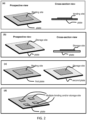
- Embodiments of the present invention manipulate the geometric size, location, contact areas, and mixing of a sample and/or a reagent using a method termed "compressed regulated open flow (CROF)", and a device that performs CROF.
- CROF compressed regulated open flow
- compressed open flow refers to a method that changes the shape of a flowable sample deposited on a plate by (i) placing other plate on top of at least a part of the sample and (ii) then compressing the sample between two plates by pushing the two plates towards each other; wherein the compression reduces a thickness of at least a part of the sample and makes the sample flow into open spaces between the plates.
- CROF compressed regulated open flow
- SCCOF self-calibrated compressed open flow
- the term "the final thickness of a part or entire sample is regulated by spacers" in a CROF means that during a CROF, once a specific sample thickness is reached, the relative movement of the two plates and hence the change of sample thickness stop, wherein the specific thickness is determined by the spacer.
- An example method of CROF as illustrated in Fig. 1 , comprises:
- plate refers to, unless being specified otherwise, the plate used in a CROF process, which a solid that has a surface that can be used, together with another plate, to compress a sample placed between the two plate to reduce a thickness of the sample.
- the plates or "the pair of the plates” refers to the two plates in a CROF process.
- first plate or “second plate” refers to the plate use in a CROF process.
- the plates are facing each other refers to the cases where a pair of plates are at least partially facing each other.
- spacers or “stoppers” refers to, unless stated otherwise, the mechanical objects that set, when being placed between two plates, a limit on the minimum spacing between the two plates that can be reached when compressing the two plates together. Namely, in the compressing, the spacers will stop the relative movement of the two plates to prevent the plate spacing becoming less than a preset (i.e. predetermined) value.
- preset i.e. predetermined
- open-spacer means the spacer have a shape that allows a liquid to flow around the entire perimeter of the spacer and flow pass the spacer.
- a pillar is an open spacer.
- enclosed spacer means the spacer of having a shape that a liquid cannot flow abound the entire perimeter of the spacer and cannot flow pass the spacer.
- a ring shape spacer is an enclosed spacer for a liquid inside the ring, where the liquid inside the ring spacer remains inside the ring and cannot go to outside (outside perimeter).
- a spacer has a predetermined height
- a spacer is fixed on its respective plate in a CROF process means that the spacer is attached to a location of a plate and the attachment to that location is maintained during a CROF (i.e. the location of the spacer on respective plate does not change).
- An example of "a spacer is fixed with its respective plate” is that a spacer is monolithically made of one piece of material of the plate, and the location of the spacer relative to the plate surface does not change during CROF.
- a spacer is not fixed with its respective plate
- a spacer is glued to a plate by an adhesive, but during a use of the plate, during CROF, the adhesive cannot hold the spacer at its original location on the plate surface and the spacer moves away from its original location on the plate surface.
- open configuration of the two plates in a CROF process means a configuration in which the two plates are either partially or completely separated apart and the spacing between the plates is not regulated by the spacers
- closed configuration of the two plates in a CROF process means a configuration in which the plates are facing each other, the spacers and a relevant volume of the sample are between the plates, the thickness of the relevant volume of the sample is regulated by the plates and the spacers, wherein the relevant volume is at least a portion of an entire volume of the sample.
- a sample thickness is regulated by the plate and the spacers in a CROF process means that for a give condition of the plates, the sample, the spacer, and the plate compressing method, the thickness of at least a port of the sample at the closed configuration of the plates can be predetermined from the properties of the spacers and the plate.
- inner surface or “sample surface” of a plate in a CROF device refers to the surface of the plate that touches the sample, while the other surface (that does not touch the sample) of the plate is termed “outer surface”.
- X-Plate of a CROF device refers to a plate that comprises spaces that are on the sample surface of the plate, wherein the spacers have a predetermined inter-spacer distance and spacer height, and wherein at least one of the spacers is inside the sample contact area.
- CROF device refers to a device that performs a CROF process.
- CROFed means that a CROF process is used.
- a sample was CROFed means that the sample was put inside a CROF device, a CROF process was performed, and the sample was hold, unless stated otherwise, at a final configuration of the CROF.
- CROF plates refers to the two plates used in performing a CROF process.
- surface smoothness or “surface smoothness variation” of a planar surface refers to the average deviation of a planar surface from a perfect flat plane over a short distance that is about or smaller than a few micrometers. The surface smoothness is different from the surface flatness variation.
- a planar surface can have a good surface flatness, but poor surface smoothness.
- surface flatness or “surface flatness variation” of a planar surface refers to the average deviation of a planar surface from a perfect flat plane over a long distance that is about or larger than 10 um.
- the surface flatness variation is different from the surface smoothness.
- a planar surface can have a good surface smoothness, but poor surface flatness (i.e. large surface flatness variation).
- relative surface flatness of a plate or a sample is the ratio of the plate surface flatness variation to the final sample thickness.
- final sample thickness in a CROF process refers to, unless specified otherwise, the thickness of the sample at the closed configuration of the plates in a CORF process.
- compression method in CROF refers to a method that brings two plates from an open configuration to a closed configuration.
- interested area or "area of interest” of a plate refers to the area of the plate that is relevant to the function that the plates perform.
- a spacer height is at most 1 um, it means that the spacer height is equal to or less than 1 um.
- sample area means the area of the sample in the direction approximately parallel to the space between the plates and perpendicular to the sample thickness.
- sample thickness refers to the sample dimension in the direction normal to the surface of the plates that face each other (e.g., the direction of the spacing between the plates).
- plate-spacing refers to the distance between the inner surfaces of the two plates.
- the term "deviation of the final sample thickness" in a CROF means the difference between the predetermined spacer height (determined from fabrication of the spacer) and the average of the final sample thickness, wherein the average final sample thickness is averaged over a given area (e.g. an average of 25 different points (4mm apart) over 1.6 cm by 1.6 cm area).
- uniformity of the measured final sample thickness in a CROF process means the standard deviation of the measured final sample thickness over a given sample area (e.g. the standard deviation relative to the average.).
- relevant volume of a sample and “relevant area of a sample” in a CROF process refers to, respectively, the volume and the area of a portion or entire volume of the sample deposited on the plates during a CROF process, that is relevant to a function to be performed by a respective method or device, wherein the function includes, but not limited to, reduction in binding time of analyte or entity, detection of analytes, quantify of a volume, quantify of a concentration, mixing of reagents, or control of a concentration (analytes, entity or reagents).
- spacer height is the dimension of the spacer in the direction normal to a surface of the plate, and the spacer height and the spacer thickness means the same thing.
- area of an object in a CROF process refers to, unless specifically stated, the area of the object that is parallel to a surface of the plate.
- spacer area is the area of the spacer that is parallel to a surface of the plate.
- lateral or “laterally” in a CROF process refers to, unless specifically stated, the direction that is parallel to a surface of the plate.
- width of a spacer in a CROF process refers to, unless specifically stated, a lateral dimension of the spacer.
- a spacer inside a sample means that the spacer is surrounded by the sample (e.g. a pillar spacer inside a sample).
- critical bending span of a plate in a CROF process refers the span (i.e. distance) of the plate between two supports, at which the bending of the plate, for a given flexible plate, sample, and compression force, is equal to an allowed bending. For example, if an allowed bending is 50 nm and the critical bending span is 40 um for a given flexible plate, sample, and compression force, the bending of the plate between two neighboring spacers 40um apart will be 50 nm, and the bending will be less than 50 nm if the two neighboring spacers is less than 40 um.
- flowable for a sample means that when the thickness of the sample is reduced, the lateral dimension increases.
- a stool sample is regarded flowable.
- a sample under a CROF process does not need to be flowable to benefit from the process, as long as the sample thickness can be reduced under a CROF process.
- a CROF process can reduce the tissue thickness and hence speed up the saturation incubation time for staining by the dye.
- the incubation/reaction time in performing assays or other chemical reactions.
- a target analyte in a sample is detected by being captured by capture agents immobilized on a plate surface (i.e. a solid phase)
- Another example is the need to shorten the time of coating a capture agent to a plate surface.
- another example is the need to shorten the time of mixing a reagent into a sample.
- Methods and devices are described that reduce (i.e. shorten) the saturation incubation time needed for binding an entity in sample to a binding site on a solid surface (i.e. the time for an entity from a volume to a surface), that reduce the time needed for a binding of an entity stored on a plate surface to a binding site on another plate surface (i.e. the time for an entity from one surface to another surface), and/or that reduce the time needed for adding/mixing of a reagent stored on a surface into a volume of a sample (i.e. a time for adding/mixing a reagent from a surface into a volume of a sample).
- the saturation incubation time of binding and/or mixing in an assay is reduced by using devices and methods that spread a sample (or a liquid) to a thinner thickness, thereby reducing the time for an entity diffusing across the sample's thickness.
- a diffusion time of an entity in a material e.g. liquid or solid or semi-solid
- a thinner thickness e.g. a tight confined space
- Reduction of the sample's thickness is made precise, uniform, fast, simple (less operation steps) and applicable to reduce the sample thickness to micrometer or nanometer thick. This has utility in fast, low-cost, PoC, diagnostics and chemical/bio analysis. Several examples are illustrated in Fig. 1-4 .
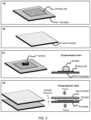
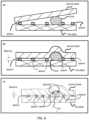
- FIG. 1-2 An example method for reducing the saturation incubation time of binding a target entity in a sample to a binding site of a plate surface is illustrated in Fig. 1-2 , 3a , and 4a , which comprises:
- a CROF reduces sample thickness but increase the sample lateral dimension. This is utilized to perform (a) local binding or mixing in portion of the sample, and (b) multiplexing of multiple binding or mixing sites, without a fluidic barrier to fluidically separate a sample into different isolation liquid pockets.
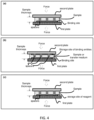
- FIG. 1 , 3c , and 4b An example method for reducing the saturation incubation time to bind an entity stored on a storage site of one plate to a relevant binding site on another plate is illustrated in Fig. 1 , 3c , and 4b , which comprises:
- the transfer medium can comprise a liquid that allows a diffusion of the entity or a reagent or both.
- the transfer medium can be a sample, where the sample contains an analyte (also termed target analyte) that binds the binding site.
- analyte also termed target analyte
- reagents additions are needed are (a) blood cell counting where anticoagulant and/or staining reagent(s) may be added into a blood sample, and (b) immunoassays where detection agents are added to bind a target analyte in solution.
- a reagent layer e.g. dried reagent layer
- a sample is deposited into the CROF device, and a CROF process makes the sample in contact with the reagent and the sample thickness thinner than the thickness when the sample at the open configuration of the CROF plates.
- Fig. 1 , 3b , and 4c An example method for reducing the time for mixing a reagent stored on a plate surface into a sample, is illustrated in Fig. 1 , 3b , and 4c , which comprises:
- the method of paragraph X5 can further comprise a step of incubation while the plates are in the closed configuration, wherein the incubation time is selected in such that results in a significant number of the reagents dissolved in the sample are contained in the relevant volume of the sample, wherein the relevant volume is the volume of the sample that sits on the storage site and the incubation is a process to allow the reagent to dissolve and diffuse in the sample.
- the method of paragraph X5 can further comprise a step that, after (d) and while the plates are in the closed configuration, incubating for a time equal or less than a factor times the diffusion time of the reagent in the sample across the sample thickness regulated by the plates at the closed configuration, and then stopping the incubation; wherein the incubation allows the reagent to diffuse into the sample; and wherein the factor is 0.0001, 0.001, 0.01, 0.1, 1, 1.1, 1.2, 1.3, 1.5, 2, 3, 4, 5, 10, 100, 1000, 10,000, or a range between any to the values. For example, if the factor is 1.1 and the diffusion time is 20 seconds, then the incubation time is equal to or less than 22 second. In preferred examples, the factor is 0.1, 1, 1.5 or a range between any to the values.
- the relevant volume of the sample can be the volume of the sample that sits on (i.e. on top of) the binding site or the storage site.
- the relevant volume of the sample can be the volume of the sample that sits on (i.e. on top of) the entire area or a partial area of the binding site or the storage site.
- the ratio of the lateral dimension of the binding site or the storage site to the sample thickness at the closed configuration can be 1.5 3 or larger, 3 or larger, 5 or larger, 10 or larger, 20 or larger, 30 or larger, 50 or larger, 100 or larger, 200 or larger, 1000 or larger, 10,000 or larger, or a range between any two of the values.
- the ratio of the lateral dimension of the binding site or the storage site to the sample thickness at the closed configuration can be between 3 and 20, 20 and 100, and 100 and 1000, or 1000 and 10,000.
- the final reduced sample thickness can be significantly smaller than that of the area of the binding site, so that the entity in the sample area that is outside of the binding site will take longer time to bind to the binding site.
- the entity that bind to the binding sites will be primarily the entity in the sample volume that sites on the binding site (i.e. the sample volume that is just above the binding area). Then the calculation of the concentration of the entity in the sample would be based on the sample thickness and the binding site area.
- the final reduced sample thickness can be significantly smaller than that of the area of the storage site, so that the entity
- the entity that bind to the binding sites will be primarily the entity in the sample volume that sites on the binding site (i.e. the sample volume that is just above the binding area). Then the calculation of the concentration of the entity in the sample would be based on the sample thickness and the binding site area.
- the final sample thickness at the closed configuration of the plates may be a significant factor in reducing the saturation incubation time.
- the sample incubation can be done in various temperatures, humidity, gas environment, and different time durations, with or without shaking.
- the method of paragraphs X1 and X3, can further comprise a step that, after (d) and while the plates are in the closed configuration, incubating for a time equal or less than a factor times the diffusion time of the entity in the sample diffusing across the sample thickness regulated by the plates at the closed configuration, and then stopping the incubation; wherein the incubation allows binding of the entity to the binding site; and wherein the factor is 0.0001, 0.001, 0.01, 0.1, 1, 1.1, 1.2, 1.3, 1.5, 2, 3, 4, 5, 10, 100, 1000, 10,000, or a range between any to the values. For example, if the factor is 1.1 and the diffusion time is 20 seconds, then the incubation time is equal to or less than 22 second. Preferably, the factor is 0.1, 1, 1.5 or a range between any to the values.
- the two plates In the open configuration, the two plates (i.e. the first plate and the second plate) are separated from each other.
- the two plates have one side connected together during all operations of the plates (including the open and closed configuration), the two plates open and close similar to a book.
- the two plates have rectangle (or square) shape and have two sides of the rectangle connected together during all operations of the plates.
- the plates are facing each other (at least a part of the plates are facing each other) and a force is used to bring the two plates together.
- the inner surfaces of the two plate compress the sample deposited on the plate(s) to reduce the sample thickness (while the sample has an open flow laterally between the plates), and the thickness of a relevant volume of the sample is determined by the spacers, the plates, and the method being used and by the sample mechanical/fluidic property.
- the thickness at a closed configuration can be predetermined for a given sample and given spacers, plates and plate pressing method.
- the term "regulation of the spacing between the inner surfaces of the plates by the spacers” or “the regulation of the sample thickness by the plates and the spacer”, or a thickness of the sample is regulated by the spacers and the plates” means that the thickness of the sample in a CROF process is determined by a given plates, spacers, sample, and pressing method.
- the regulated sample thickness at the closed configuration can be the same as the height of a spacer; in this case, at the closed configuration, the spacers directly contact both plates (wherein one plate is the one that the spacer is fixed on, and the other plate is the plate that is brought to contact with the spacer).
- the regulated sample thickness at the closed configuration can be larger than the height of a spacer; in this case, at the closed configuration, the spacers directly contacts only the plate that has the spacers fixed or attached on its surface, and indirectly contact the other plate (i.e. indirect contact).
- the term "indirect contact” with a plate means that the spacer and the plate is separated by a thin sample layer, which is termed “residual sample layer” and its thickness is termed "the residue thickness”.
- residual thickness can be predetermined (predetermined means prior to reach the closed configuration), leading to a predetermination of the sample thickness at the closed configuration. This is because the residue layer thickness is the same for the given conditions (the sample, spacers, plates, and pressing force) and can be pre-calibrated and/or calculated.
- the regulated sample thickness is approximately equal to the spacer height plus the sample residue thickness.
- the plates are made of any material that (i) is capable of being used to regulate, together with the spacers, the thickness of a portion or entire volume of the sample, and (ii) has no significant adverse effects to a sample, an assay, or a goal that the plates intend to accomplish.
- the two plates can have the same or different parameters for each of the following parameters: plate material, plate thickness, plate shape, plate area, plate flexibility, plate surface property, and plate optical transparency.
- the plates are made a single material, composite materials, multiple materials, multilayer of materials, alloys, or a combination thereof.
- Each of the materials for the plate is an inorganic material, am organic material, or a mix, wherein examples of the materials are given in paragraphs of Mat-1 and Mat-2.
- the inorganic materials for the plates include, not limited to, glass, quartz, oxides, silicon-dioxide, silicon-nitride, hafnium oxide (HfO), aluminum oxide (AlO), semiconductors: (silicon, GaAs, GaN, etc.), metals (e.g. gold, silver, coper, aluminum, Ti, Ni, etc.), ceramics, or any combinations of thereof.
- the organic materials for the spacers include, not limited to, polymers (e.g. plastics) or amorphous organic materials.
- the polymer materials for the spacers include, not limited to, acrylate polymers, vinyl polymers, olefin polymers, cellulosic polymers, noncellulosic polymers, polyester polymers, Nylon, cyclic olefin copolymer (COC), poly(methyl methacrylate) (PMMA), polycarbonate (PC), cyclic olefin polymer (COP), liquid crystalline polymer (LCP), polyamide (PA), polyethylene (PE), polyimide (PI), polypropylene (PP), poly(phenylene ether) (PPE), polystyrene (PS), polyoxymethylene (POM), polyether ether ketone (PEEK), polyether sulfone (PES), poly(ethylene phthalate) (PET), polytetrafluoroethylene (PTFE), polyvinyl chloride (PVC
- Plates can be made of at least one of glass, plastic, ceramic, and metal.
- one plate is different from the other plate in lateral area, thickness, shape, materials, or surface treatment. In some embodiments, one plate is the same as the other plate in lateral area, thickness, shape, materials, or surface treatment.
- the rigidity (i.e. stiffness) or flexibility of a plate is defined relative to a given pressing forces used in bringing the plates into the closed configuration.
- One or both plates are flexible.
- At least one of the two plates are transparent (to a light). In some embodiments at least a part or several parts of one plate or both plates are transparent. In some embodiments, the plates are non-transparent.
- the average thicknesses for at least one of the pates can be 2 nm or less, 10 nm or less, 100 nm or less, 500 nm or less, 1000 nm or less, 2 um (micron) or less, 5 um or less, 10 um or less, 20 um or less, 50 um or less, 100 um or less, 150 um or less, 200 um or less, 300 um or less, 500 um or less, 800 um or less, 1 mm (millimeter) or less, 2 mm or less, 3 mm or less, or a range between any two of the values.
- the average thicknesses for at least one of the plates can be at most 3 mm (millimeter), at most 5 mm, at most 10 mm, at most 20 mm, at most 50 mm, at most 100 mm, at most 500 mm, or a range between any two of the values.
- the thickness of a plate does not need to be uniform across the plate. Using a different plate thickness at different location can be used to control the plate bending, folding, sample thickness regulation, and others.
- the plates can have any shapes, as long as the shape allows a compress open flow of the sample and the regulation of the sample thickness. However, certain shapes may be advantageous.
- the shape of the plate can be round, elliptical, rectangles, triangles, polygons, ring-shaped, or any superpositions of these shapes.
- the two plates can have the same size or shape, or different.
- the area of the plates depend on the application.
- an inner surface of the plates are flat or significantly flat, planar.
- the two inner surfaces are, at the closed configuration, parallel with each other.
- Flat inner surfaces facilitates a quantification and/or controlling of the sample thickness by simply using the predetermined spacer height at the closed configuration.
- For non-flat inner surfaces of the plate one need to know not only the spacer height, but also the exact the topology of the inner surface to quantify and/or control the sample thickness at the closed configuration. To know the surface topology needs additional measurements and/or corrections, which can be complex, time consuming, and costly.
- a flatness of the plate surface is relative to the final sample thickness (the final thickness is the thickness at the closed configuration), and is often characterized by the term of "relative surface flatness” is the ratio of the plate surface flatness variation to the final sample thickness.
- a plate is optical transparent. In some embodiments, both plates are optical transparent. In some embodiments, a plate is optical transparent and another plate is opaque. In some embodiments, both plates are opaque. In some embodiments, both plate are optical transparent but have different optical transparency. The optical transparency of a plate refers a part or the entire area of the plate.
- a plate has an inner surface that wets (i.e. contact angle is less 90 degree) the sample, the transfer liquid, or both. In some embodiments, both plates have an inner surface that wets the sample, the transfer liquid, or both; either with the same or different wettability. In some embodiments, a plate has an inner surface that wets the sample, the transfer liquid, or both; and another plate has an inner surface that does not wet (i.e. the contact angle equal to or larger than 90 degree).
- the wetting of a plate inner surface refers a part or the entire area of the plate.
- the inner surface of the plate has other nano or microstructures to control a lateral flow of a sample during a CROF.
- the nano or microstructures include, but not limited to, channels, pumps, and others. Nano and microstructures are also used to control the wetting properties of an inner surface.
- the spacers are configured to (1) control, together with the plates, the thickness of the sample or a relevant volume of the sample.
- the spacers may also be configured to: (2) allow the sample to have a compressed regulated open flow (CROF) on plate surface; (3) not take significant surface area (volume) in a given sample area (volume); (4) reduce or increase the effect of sedimentation of particles or analytes in the sample; (5) change and/or control the wetting propertied of the inner surface of the plates; (6) identify a location of the plate, a scale of size, and/or the information related to a plate, or (7) do any combination of the above.
- CROF compressed regulated open flow
- the spacers There are two kinds of the spacers: open-spacers and enclosed-spacers.
- the open-spacer is the spacer that allows a sample to flow through the spacer (i.e. the sample flows around and pass the spacer.
- a post as the spacer.
- the enclosed spacer is the spacer that stop the sample flow (i.e. the sample cannot flow beyond the spacer.
- a ring shape spacer and the sample is inside the ring.
- Both types of spacers use their height to regular the final sample thickness at a closed configuration.
- the spacers may be open-spacers only.
- the spacers may be enclosed-spacers only.
- the spacers can be a combination of open-spacers and enclosed-spacers.
- pillar spacer means that the spacer has a pillar shape and the pillar shape refers to an object that has height and a lateral shape that allow a sample to flow around it during a compressed open flow.
- the lateral shapes of the pillar spacers may be a shape selected from the groups of (i) round, elliptical, rectangles, triangles, polygons, ring-shaped, star-shaped, letter-shaped (e.g. L-shaped, C-shaped, the letters from A to Z), number shaped (e.g. the shapes like 0 1, 2, 3, 4, .... to 9); (ii) the shapes in group (i) with at least one rounded corners; (iii) the shape from group (i) with zig-zag or rough edges; and (iv) any superposition of (i), (ii) and (iii).
- different spacers can have different lateral shape and size and different distance from the neighboring spacers.
- the spacers may be and/or may include posts, columns, beads, spheres, and/or other suitable geometries.
- the lateral shape and dimension (i.e., transverse to the respective plate surface) of the spacers can be anything, except the following restrictions: (i) the spacer geometry will not cause a significant error in measuring the sample thickness and volume; or (ii) the spacer geometry would not prevent the out-flowing of the sample between the plates (i.e. it is not in enclosed form). Some cases require some spacers to be closed spacers to restrict the sample flow.
- the shapes of the spacers may have rounded corners.
- a rectangle shaped spacer has one, several or all corners rounded (like a circle rather 90 degree angle).
- a round corner often make a fabrication of the spacer easier, and in some cases less damage to a biological material.
- the sidewall of the pillars can be straight, curved, sloped, or different shaped in different section of the sidewall.
- the spacers can be pillars of various lateral shapes, sidewalls, and pillar-height to pillar lateral area ratio.
- the spacers may have shapes of pillars for allowing open flow.
- the spacers are generally made of any material that is capable of being used to regulate, together with the two plates, the thickness of a relevant volume of the sample.
- the materials for the spacers are different from that for the plates.
- the materials for the spaces are at least the same as a part of the materials for at least one plate.
- the spacers are made a single material, composite materials, multiple materials, multilayer of materials, alloys, or a combination thereof.
- Each of the materials for the spacers is an inorganic material, am organic material, or a mix, wherein examples of the materials are given in paragraphs of Mat-1 and Mat-2.
- the spacers are made in the same material as a plate used in CROF.
- the mechanical strength of the spacers can be strong enough, so that during the compression and at the closed configuration of the plates, the height of the spacers is the same or significantly same as that when the plates are in an open configuration.
- the differences of the spacers between the open configuration and the closed configuration can be characterized and predetermined.
- the material for the spacers is rigid, flexible or any flexibility between the two.
- the rigid is relative to a give pressing forces used in bringing the plates into the closed configuration: if the space does not deform greater than 1% in its height under the pressing force, the spacer material is regarded as rigid, otherwise a flexible.
- the final sample thickness at a closed configuration still can be predetermined from the pressing force and the mechanical property of the spacer.
- Inter-spacer distance Clearly, for maintaining a given sample thickness variation between two neighboring spacers, when a more flexible plate is used, a closer inter-spacer distance is needed.
- a spacer is fixed with its respective plate
- the term "a spacer is fixed with its respective plate” means that the spacer is attached to a plate and the attachment is maintained during a use of the plate.
- An example of "a spacer is fixed with its respective plate” is that a spacer is monolithically made of one piece of material of the plate, and the position of the spacer relative to the plate surface does not change.
- An example of "a spacer is not fixed with its respective plate” is that a spacer is glued to a plate by an adhesive, but during a use of the plate, the adhesive cannot hold the spacer at its original location on the plate surface (i.e. the spacer moves away from its original position on the plate surface).
- a spacer can be fixed to a plate monolithically.
- the spacers can be fixed to their respective plate by one or any combination of the following methods and/or configurations: attached to, bonded to, fused to, imprinted, and etched.
- imprinted means that a spacer and a plate are fixed monolithically by imprinting (i.e. embossing) a piece of a material to form the spacer on the plate surface.
- the material can be single layer of a material or multiple layers of the material.
- etched means that a spacer and a plate are fixed monolithically by etching a piece of a material to form the spacer on the plate surface.
- the material can be single layer of a material or multiple layers of the material.
- fused to means that a spacer and a plate are fixed monolithically by attaching a spacer and a plate together, the original materials for the spacer and the plate fused into each other, and there is clear material boundary between the two materials after the fusion.
- bonded to means that a spacer and a plate are fixed monolithically by binding a spacer and a plate by adhesion.
- attached to means that a spacer and a plate are connected together.
- the spacers and the plate are made in the same materials. In other embodiment, the spacers and the plate are made from different materials. In other embodiment, the spacer and the plate are formed in one piece. In other embodiment, the spacer has one end fixed to its respective plate, while the end is open for accommodating different configurations of the two plates.
- each of the spacers independently is at least one of attached to, bonded to, fused to, imprinted in, and etched in the respective plate.
- independently means that one spacer is fixed with its respective plate by a same or a different method that is selected from the methods of attached to, bonded to, fused to, imprinted in, and etched in the respective plate.
- a larger plate holding force i.e. the force that holds the two plates together
- a smaller plate spacing for a given sample area
- a larger sample area for a given plate-spacing
- At least one of the plates is transparent in a region encompassing the relevant area, each plate has an inner surface configured to contact the sample in the closed configuration; the inner surfaces of the plates are substantially parallel with each other, in the closed configuration; the inner surfaces of the plates are substantially planar, except the locations that have the spacers; or any combination of thereof.
- the spacers can be fabricated on a plate in a variety of ways, using lithography, etching, embossing (nanoimprint), depositions, lift-off, fusing, or a combination of thereof.
- the spacers can be directly embossed or imprinted on the plates.
- the spacers can be imprinted into a material (e.g. plastics) that is deposited on the plates.
- the spacers can be made by directly embossing a surface of a CROF plate.
- the nanoimprinting may be done by roll to roll technology using a roller imprinter, or roll to a planar nanoimprint. Such process has a great economic advantage and hence lowering the cost.
- the spacers can be deposited on the plates.
- the deposition can be evaporation, pasting, or a lift-off.
- the spacer is fabricated first on a carrier, then the spacer is transferred from the carrier to the plate.
- the lift-off a removable material is first deposited on the plate and holes are created in the material; the hole bottom expose the plate surface and then a spacer material is deposited into the hole and afterwards the removable material is removed, leaving only the spacers on the plate surface.
- the spacers deposited on the plate are fused with the plate.
- the spacer and the plates are fabricated in a single process. The single process includes imprinting (i.e. embossing, molding) or synthesis.
- At least two of the spacers may be fixed to the respective plate by different fabrication methods, and optionally wherein the different fabrication methods include at least one of being deposition, bonded, fuse, imprinted, and etched.
- One or more of the spacers may fixed to the respective plate(s) by a fabrication method of being bonded, being fused, being imprinted, or being etched, or any combination of thereof.
- the fabrication methods for forming such monolithic spacers on the plate include a method of being bonded, being fused, being imprinted, or being etched, or any combination of thereof.
- scale-marker(s) refers to the scale-marker(s) that able to assist a quantification (i.e. dimension measurement) or a control of the relevant area and/or the relative volume of a sample.
- the scale-markers can be on the first plate or the second plate, on both on plates, on one surface of the plate, on both surfaces of the plate, between the plates, near the plates, or any combination of thereof.
- the scale-markers are fixed on the first plate or the second plate, on both on plates, on one surface of the plate, on both surfaces of the plate, between the plates, near the plates, or any combination of thereof.
- the scale-markers are deposited on the first plate or the second plate, on both on plates, on one surface of the plate, on both surfaces of the plate, between the plates, near the plates, or any combination of thereof.
- the scale-marks can be etched scale-marks, deposited materials, or printed materials.
- the scale-markers can be a or a plurality of object(s) with known dimensions and/or known separation distances. Examples of the objects include, not limited to, rectangles, cylinders, or circles.
- the scale-markers can have a dimension of in the range of nanometers (nm), microns (um) or millimeters (mm) or other sizes.
- the scale-markers can be a ruler, which has scale scale-marks that are configured to measure a dimension of an object.
- the scale-marks may be in the scale of nanometer (nm), microns (um) or millimeter (mm) or other sizes.
- the scale marks can be etched scale-marks, deposited materials, or printed materials.
- the materials for the scale-markers can be the materials that absorbing the light, reflecting light, scattering light, interfering light, diffracting light, emitting light, or any combination of thereof.
- the makers are the spacers, which server dual functions of "regulating sample thickness” and “providing scale-marking and/or dimension scaling".
- a rectangle spacer with a known dimension or two spacers with a known separation distance can be used to measure a dimension related to the sample round the spacer(s). From the measured sample dimension, one can calculate the volume of the relevant volume of the sample.
- the scale-markers is configured to at least partially define a boundary of the relevant volume of the sample.
- At least one of the scale-markers is configured to have a known dimension that is parallel to a plane of the lateral area of the relevant volume of the sample.
- At least a pair of the scale-markers are separated by a known distance that is parallel to a plane of the lateral area.
- the scale-markers are configured for optical detection.
- each scale-marker independently is at least one of light absorbing, light reflecting, light scattering, light diffracting, and light emitting.
- the scale-markers are arranged in a regular array with a known lateral spacing.
- each scale-marker independently has a lateral profile that is at least one of square, rectangular, polygonal, and circular.
- At least one of the scale-markers is attached to, bonded to, fused to, imprinted in, and etched in one of the plates.
- At least one of the scale-markers is one of the spacers.
- some spacers also play a role of scale-marker to quantification of a relevant volume of the sample.
- a binding site(s) (that immobilizes the analytes), storage sites, or alike, serves as a scale-marker(s).
- the site with a known lateral dimension interacts with light generating a detectable signal, that reals the known lateral dimension of the site, hence serving a scale-marker(s).
- the dimension of the sites are predetermined before a CROF process and the thickness of the portion of the sample sitting on the site is, when the plates are at the closed configuration, significantly smaller than the lateral average dimension of the site, then by controlling the incubation time so that, after the incubation, (1) the majority of the analytes/entity that bind to the binding site come from the sample volume that sites on top of the binding site, or (2) the majority of the reagent that is mixed (diffused) into the sample volume that sites on top of the binding site come from the storage site.
- the relevant volume of the sample to the binding or the reagent mixing is the volume that is approximately equal to the predetermined site area multiplies the sample thickness at the site.
- an assay has a binding site (i.e. the area with capture agents) of 1,000 um by 1000 um on a first plate of a CROF process (which has a surface large than the binding site); at the closed configuration of the plates, a sample with analytes is over the binding site, has a thickness of about 20 um (in the bind site area) and an area larger than the binding site and is incubated for a time equal to the target analyte/entity diffusion time across the sample thickness.
- a binding site i.e. the area with capture agents
- a first plate of a CROF process which has a surface large than the binding site
- the signal due to the analytes/entity captured by the binding site, is measured after the incubation, one can determine the analyte/entity concentration in the relevant area and relevant volume of the sample from the information (provided by the binding site) of the relevant area and relevant volume.
- the analyte concentration is quantified by the number of analytes captured by the binding site divided the relevant volume.
- the relevant volume is approximately equal to the binding site area times the sample thickness
- the target analyte concentration in the sample is approximately equal to the number of analyte captured by the binding site divided by the relevant sample volume.
- Guard Ring Some embodiments have a guard ring to prevent sample flow out of the plate surface. Some embodiments of the guard ring is an enclosed wall around the sample area. The wall has a height equal to the spacer height or different from the spacer height. The wall ca be a significant distance away from the sample measurement area.
- the movable plates in a CROF process may include and/or may be coupled to a hinge, a stage, or some other positioning system that is configured to transition the plates between an open configuration and a closed configuration.
- Movable plates may be coupled together with one or more joints in a manner that leaves an opening to access the space between the plates (e.g., to insert and/or remove sample), provided that at least one of the joints and/or at least one of the plates is flexible enough to achieve the described open and closed configurations.
- a membrane pump is not considered to be a movable plate(s).
- the present invention provides the means to improve the uniformity.
- the factors that can degrade the uniformity of the plate spacing in CROF include (a) a local bending of a plate, (b) a non-flatness of the inner surface of a plate, and (c) dusts.
- CROF plates flexible.
- a flexible plate e.g. a plastic thin film
- the flexibility of the plate(s) can lead a local bending (e.g. sag, namely bending inward) of the plate at the locations that are between the two neighboring spacers, leading to a poor sample thickness uniformity.
- a poor sample thickness uniformity has many disadvantages, such as large errors in determining the sample volume and/or analytes concentration, variation of the incubation time, etc.
- the configuration of the spacers comprises selecting a proper inter spacer distance.
- the inter spacer distance is selected, so that for an allowed sample thickness variation, given two plate, and a compression method, the bending of the two plates, under the compression method, is equal to or less than the allowed sample thickness variation.
- the regulated sample thickness at the closed configuration can be thinner than the maximum thickness of the sample when the plates are in the open configuration
- Small interspace spacing can also allow to use flexible thin films (e.g. Plastic file of 100um thick) by making the inter-spacer distance less than the bending f the plate between two spacers.
- flexible thin films e.g. Plastic file of 100um thick
- the problem can be solved by using a proper flexible plate(s) and inter spacer distance to limit the effect of the dust in a small area around the dust, while allowing the area outside the small area to have a final plate spacing and sample thickness set (regulated) by the spacers).
- Fig. 6b illustrates that, to overcome the effects of the dust, one flexible plate with a proper flexibility is used to limit the dust area, and it is used together with a rigid plate that has fixed spacers.
- Fig. 6c shows another configuration for reducing the dust effect, where the spacers are fixed on the flexible plate.
- another solution is to make both plates flexible.
- the proper flexibility of the plates to minimize the effects of the dust in a CROF process can be selected from the thickness and the mechanical property of the plate.
- the configuration of the spacers and plates for minimizing the dust effect area comprises selecting a proper thickness and mechanical property of the flexible plate.
- the inter spacer distance can be selected, so that for an allowed sample thickness variation, given two plate, and a compression method, the bending of the two plates, under the compression method, is equal to or less than the allowed sample thickness variation.
- the regulated sample thickness at the closed configuration can be thinner than the maximum thickness of the sample when the plates are in the open configuration.
- a surface flatness variation can be significantly large compared with a desired sample thickness, which can causes large errors in determining a sample thickness.
- a surface flatness variation can increasingly cause significant errors.
- a surface flatness variation can be characterized by the surface flatness variation distance of a plate, ⁇ , is the distance from a local maximum of a surface height to a neighboring local minimum (illustrated in Fig. 7b ).
- the variation of the final sample thickness at the closed configuration of a CROF process can be made smaller than the surface flatness variation on the sample surface of the plates that was existed when the plates in an open configuration.
- An approach for achieving a uniform final sample thickness is to use a flexible plate, a proper inter-spacer distance, and proper compressing force (illustrated in Fig. 7c and d) .
- the sample surface of the rigid plate has a good flatness, but the sample surface of the flexible plate has a significant surface flatness variation (i.e. significant compared to the intended final sample thickness), as illustrated in Fig. 7a and b.
- the initial flatness variation of the sample surface at an open configuration can be corrected (e.g.
- the inter-spacer distance should also be smaller than the critical bending span of the flexible plate as well.
- the above method of correcting surface flatness variation also works for the cases (a) the rigid plate has an initial significant sample surface flatness variation while the flexible plate has a smooth sample surface, (b) both the flexible plate and the rigid plate have significant flatness variation on their prospective sample surface, and (c) both plates are flexible and the sample surface(s) of one or both plate(s) has significant surface flatness variation ( Fig. 7d ).
- the predetermined inter-spacer distance is configured to limit a local bending of the plates between two spacers, and wherein the relevant volume is a portion or an entire volume of the sample.
- the sample is deposited by several methods or a combination of the methods.
- the sample can be deposited on only one plate.
- the sample can be deposited on both plates (i.e. the first and the second plate).
- the sample is deposited when the plates are at an open configuration.
- the deposition of the sample can be a single drop or multiple drops.
- the multiple drops can be at one location or multiple locations of either one plate or both plates.
- the droplets can be well separated from each other, connected, or a combination of thereof.
- a sample may comprise more than one materials, and the materials are deposited together or separately. The materials are deposited separately either in parallel or sequence.
- the deposition of the sample to the plates can be performed using a device or directly from test subject to the plates.
- a sample may be deposited using a device including, but not limited to, pipettes, needle, stick, swab, tube, jet, liquid dispenser, tips, stick, inkjets, printers, spraying devices, etc.
- a sample may be deposited by a direct contacting between the sample at the sample source and a CROF plate without using any devices (i.e. bring the sample and the plate together to make a contact between the two). This is termed "direct sample deposition".
- Examples of a direct sample deposition of a sample to a plate(s) are (a) a direct contact of between pricked finger (or other body parts) and a plate, (b) spitting saliva onto the plate(s), (c) taking a tear in human eyes by a direct contact between the tear and the plate(s), (d) a direct contact between the sweat and the plate(s), and (e) a direct breathing onto the plate(s) to deposit a breath, etc.
- Such direct deposition method can be used for both human and animals.
- Both a direct and indirect (through a device) sample deposition can be used.
- the volume of the sample that is deposited on the plate or the plates is at most 0.001 pL (pico liter), at most 0.01 pL, at most 0.1 pL, at most 1 pL, at most 10 pL, at most 100 pL, at most 1 nL (nano liter), at most 10 nL, at most 100 nL, at most 1 uL (micro liter), at most 10 uL, at most 100 uL, at most 1 mL (milliliter), at most 10 mL, or a range of any two of these values.
- the depositing of a sample may comprise the steps of (a) put a sample on one or both of the plates, and (b) spreading the sample using a means other than the second plate compression in a CROF process.
- the means of spreading the sample include using another device (e.g. stick, blade), air blow, or others.
- the samples can behave approximately like an incompressible liquid (which refers a liquid that maintains a constant volume under a shape deformation), therefore a change in the sample thickness would lead to the change in the sample area.
- an incompressible liquid which refers a liquid that maintains a constant volume under a shape deformation
- the samples behave like a compressible liquid, yet their lateral area still expand when their thickness is reduced during a CROF process.
- the sample may be liquid, gel, or soft-solids, as long as that, during a CROF process, their lateral area expands when their thickness is reduced.
- the entity may include, but not limited to, one of a protein, an amino acid, a nucleic acid, a lipid, a carbohydrate, a metabolite, a cell, or a nanoparticle.
- the binding site may include a binding partner configured to bind to the respective entity.
- the binding site includes an entity bound to the binding site.
- Placing the sample may include placing the sample within the binding site.
- the reagent includes at least one of a protein, an amino acid, a nucleic acid, a lipid, a carbohydrate, and a metabolite.
- the storage site includes dried reagent.
- the storage site includes reagent configured to be released from the storage site upon contact with the sample.
- the first storage site and the second storage site are in a common storage site.
- the transfer media is a sample. In some embodiments, the transfer media is a liquid, wherein the reagent or the entity can be dissolved and diffuse in the liquid.
- a plate has multiple storage sites. In another embodiment, one storage site has multiple reagent.
- a plate has multiple storage sites on different locations of the plate or one storage site stores multiple reagent, and upon in touch with the sample by the storage sites, the reagents are released but released at different time for different reagents on the same storage site or reagents on different storage sites.
- the first reagent is configured to be released from the first storage site upon contact with the sample in a first average release time and the second reagent is configured to be released from the second storage site upon contact with the sample in a second average release time, and wherein the first average release time is less than the second average release time.
- the first reagent is configured to be released from the first storage site upon contact with the sample and wherein the second reagent is a bound reagent.
- the reagent includes at least one of a protein, an amino acid, a nucleic acid, a lipid, a carbohydrate, and a metabolite.
- the storage site includes dried reagent.
- the storage site includes reagent configured to be released from the storage site upon contact with the sample
- a binding site to capture (i.e. bind) the analytes only in a portion of a sample, not in the entire sample. It is also desirable in some cases that a reagent is added (i.e. mixed) into a port of a sample, not the entire sample. It is often desirable that there is no fluidic separation between the portion of the sample and the rest of the sample. Such requirements are preferable or necessary in certain multiplexed detections.
- the present invention offers a solution to the above requirements by using a CROF method and device to reshape a sample into a ultra-thin film of a thickness, that is smaller than the lateral dimension of the portion of the sample, wherein only an analyte inside that portion of the sample will be captured, or only the portion of the sample will be mixed with a reagent.
- the working principle for such approach is that when the thickness of the sample is smaller than the lateral dimension of the portion of the sample, a capture of an analyte by a surface or a mixing of reagent placed on a surface can be primarily limited by the diffusion of the analytes and the reagent in the thickness direction, where the diffusion in the lateral diffusion is relatively insignificant.
- a sample is reshaped in to a thin film of 5 um thick
- the portion of the sample that an analyte should be captured or a reagent should be mixed has a lateral dimension of 5 mm by 5 mm
- the diffusion time of analyte or reagent across the 5 um is 10 sec
- the lateral diffusion of the analyte or the reagent across the 5 mm distance is 1,000,000 sec (since the diffusion time is proportional to the square of the diffusion distance).
- An example method for locally binding target entities in a relevant volume of a sample to a binding site on a surface comprises:
- the regulation of the thickness of the relevant volume to 3 times less than the average linear dimension of the binding site makes the diffusion time of the entity across the sample thickness is 9 times less than that across a distance equal to the average linear dimension of the binding site.
- Such thickness regulation makes it possible to select an incubation time, such that the incubation results in (i) a significant number of target entity in the relevant volume are bound to the binding site and (ii) a significant number of the target entity bound to the binding site are from the relevant volume of the sample, and wherein the incubation is a process to allow the target entity to bind to the binding site.
- the incubation time is set to be the time that equals to the diffusion time of the entity across the thickness of the relevant volume of the sample.
- An example method for locally binding entity stored on a storage site of one plate to a binding site on another plate comprises:
- the term of "at least a port of the storage site is directly facing the binding site” means that the shortest distance from a point in the portion to the binding site is the same as the thickness of the relevant volume at the closed configuration of the plates.
- An example method for locally binding entity stored on multiple storage sites of one plate to multiple corresponding binding sites on another plate comprises:
- An example method for locally adding a reagent into a relevant volume of a sample comprises:
- a capture-analyte-detection sandwich can be formed on a binding site on a solid surface in a single step by using a CROF process and by putting the binding site on one plate and a storage site which stores the detection agent on the corresponding location of the other plate.
- An example method for forming a capture-analyte-detection sandwich on a binding site of a plate comprises:
- An example method for forming a capture-analyte-detection sandwich on a binding site of a plate using the analytes that are from a portion of the sample comprises:
- the ratio of the spacing to the site dimension may be less than 1/5.
- An example method for reducing the time of forming a capture-analyte-detection sandwich on a binding site of a plate comprises:
- the method may further be multiplexed, as described above or below.
- the method may comprise attaching a capture agent a plate, wherein the attaching is done via a chemical reaction of the capture agent with a reactive group on the plate.
- the other plate may contain a patch of a dried detection reagent at a location such that, after the plates are closed, the affixed capture agent and the patch of detection reagent are facing each other.
- the method may comprise contacting a sample containing a target-analyte with the device and closing the plates, as described above.
- the detection reagent dissolves and diffuses into the sample. Since the target analyte is in solution, the target analyte will be bound by the capture agent and immobilized to the surface of one of the plates.
- the detection agent can bind to the target analyte before or after it is bound to the capture agent.
- the method may comprises removing any target-analytes that are not bound to the capture agent, or any unbound detection reagent (e.g., by washing the surface of a plate in binding buffer);
- the detection agent may be conjugated with an optical detectable label, thereby providing a way to detect the target analyte.
- the system can be read, e.g., using a reading system, to read a light signal (e.g., light at a wavelength that is in the range of 300 nm to 1200 nm) from detection agent that is bound to the plate.
- a light signal e.g., light at a wavelength that is in the range of 300 nm to 1200 nm
- the detection agent may be labeled directly (in which case the detection agent may be strongly linked to a light-emitting label prior to deposition onto one of the plates), or labeled indirectly (i.e., by binding the detection agent to a second capture agent, e.g., a secondary antibody that is labeled or a labeled nucleic acid, that specifically binds to the detection agentt and that is linked to a light-emitting label).
- the method may comprise a blocking agent, thereby preventing non-specific binding of the capture agents to non-target analytes.
- Suitable conditions for the specific binding of target analytes to other agents include proper temperature, time, solution pH level, ambient light level, humidity, chemical reagent concentration, antigen-antibody ratio, etc., are all well known or readily derivable from the present disclosure.
- General methods for methods for molecular interactions between capture agents and their binding partners are well known in the art (see, e.g., Harlow et al,. Antibodies: A Laboratory Manual, First Edition (1988) Cold spring Harbor, N.Y .; Ausubel, et al, Short Protocols in Molecular Biology, 3rd ed., Wiley & Sons, 1995 ).
- a nucleic acid capture agent can be used to capture a protein analyte (e.g., a DNA or RNA binding protein).
- a protein analyte e.g., a DNA or RNA binding protein
- the protein capture agent e.g., a DNA or RNA binding protein
- the sample may be a clinical sample derived from cells, tissues, or bodily fluids.
- Bodily fluids of interest include but are not limited to, amniotic fluid, aqueous humour, vitreous humour, blood (e.g., whole blood, fractionated blood, plasma, serum, etc.), breast milk, cerebrospinal fluid (CSF), cerumen (earwax), chyle, chime, endolymph, perilymph, feces, gastric acid, gastric juice, lymph, mucus (including nasal drainage and phlegm), pericardial fluid, peritoneal fluid, pleural fluid, pus, rheum, saliva, sebum (skin oil), semen, sputum, sweat, synovial fluid, tears, vomit, urine and exhaled condensate.
- a plate is contacted with a sample containing a target analyte (e.g., a target protein) and the plates are closed.
- a target analyte e.g., a target protein
- the sample contains, or is amended to contain, all necessary reagents (e.g., salts and the like) conditions suitable for specific binding.
- the capture agents e.g., antibodies
- detection agent specifically bind to a target analyte in the sample, thereby leading to a patch of labeled analyte that can be detected.
- the amount of target analyte in the sample can be measured to provide a qualitative or quantitative measure of the amount of target analyte in the sample.
- the magnitude of the signal can provide a quantitative determination of the amount of target analyte in the sample.
- the evaluation may be compared to a standard curve (e.g., of a second analyte or a spiked-in analyte) that may in certain cases be at a known concentration. This comparison may be facilitated by depositing capture agents at different densities (e.g., different concentrations) and reading the signal from each patch of capture agent.
- One aspect of the present invention is to significantly reduce the volume of the sample or reagent used in a testing, by depositing a tiny volume of a sample or a reagent on a plate and then reshaping the volume into a thin film with a smaller thickness but larger area than before. Such reshaping also allows faster reaction.
- An example method for binding target entity in a sample to a binding site comprises:
- An example method for binding target entity in a sample to a binding site comprises:
- Drops of a sample can be multiple drops, and in the closed configuration, the drops merged into a film with a thickness less than the maxmimun thickness.
- sample volume The volume of the sample that is deposited on the plate or the plates (“sample volume”) is at most 0.001 pL (pico liter), at most 0.01 pL, at most 0.1 pL, at most 1 pL, at most 10 pL, at most 100 pL, at most 1 nL (nano liter), at most 10 nL, at most 100 nL, at most 1 uL (micro liter), at most 10 uL, at most 100 uL, at most 1 mL (milliliter), at most 10 mL, or a range of any two of these values.
- the examples include binging of entity of sample to a surface binding site, adding reagents into a sample, quantification a relevant volume of the sample, quantification of analytes, and others.
- binging of entity of sample to a surface binding site adding reagents into a sample
- quantification a relevant volume of the sample quantification of analytes, and others.
- One aspect of the present invention is to improve the precision, uniformity, or easy-to-use of the methods and/or devices that regulate a thickness of a relevant volume of a sample by compressing the sample with two plates.
- An example method for uniformly binding an entity in a sample into a binding site of a plate comprises:
- An example method for uniformly adding a reagent into a relevant volume of a sample comprises:
- An example method for regulating a thickness of a relevant volume of a sample comprises:
- the saturation incubation time can vary from location to location in the binding site, forcing a longer saturation incubation time to ensure all locations in the binding site having reached the saturation.
- SAS signal amplification surface
- SAL signal amplification layers
- the general structures of SAL comprise nanoscale metal-dielectric/semiconductor-metal structures, which amplifies local surface electric field and gradient and light signals.
- the amplification are the high at the location where there are the sharp (i.e. large curvature) edges of a metal structure and the between a small gaps of the two metal structures.
- the highest enhancement regions are those having both the sharp edges and the small gaps.
- the dimensions for all metallic and non-metallic micro/nanostructures generally are less than the wavelength of the light the SAL amplifies (i.e., subwavelength).
- a SAL layer has as many of the metallic sharp edges and the small gaps as possible. This requires having a dense group of metallic nanostructures with small gaps between the nanostructures. SAL structures may include several different layers. Furthermore, the SAL layer itself can be further improved by a process that can further cover the portions of the metallic materials that do not have sharp edges and small gaps, as described in US provisional application serial no. 61/801,424, filed on March 15, 2013 , and PCT application WO2014197096, filed on March 15, 2014 , as well as PCT/US2014/028417 ( Chou et al, "Analyte Detection Enhancement By Targeted Immobilization, Surface Amplification, And Pixelated Reading And Analysis ").
- a signal amplification surface is the D2PA array (disk-coupled dots-on-pillar antenna arrays), which may also comprise a molecular adhesion layer that covers at least a part of said metallic dot structure, said metal disc, and/or said metallic back plane and, optionally, a capture agent that specifically binds to an analyte, wherein said capture agent is linked to the molecular adhesion layer of the D2PA array.
- the nanosensor can amplify a light signal from an analyte, when said analyte is bound to the capture agent.
- the dimension of one, several or all critical metallic and dielectric components of SAL are less than the wavelength of the light in sensing.
- An example method for amplifying the signal of assaying a target entity in a relevant volume of a sample comprises:
- the signal amplification surface may include at least one of a metal-dielectric nanostructure, a metal-semiconductor nanostructure, and a disk-coupled dots-on-pillar antenna array.
- the signal amplification surface may include a metal layer.
- the typical diffusion length is about 10 um, 33 um, and 100 um, respectively, for an incubation time of 1 s (second), 10 s and 100 s.
- a typical thickness of a liquid drop on a typical surface is 2.5 mm, which is at least 25 time thicker than the above diffusion lengths, leading significant waste (costly) if the incubation time is 100 s or less. It is possible to spread a drop (or drops) of reagent into a large area but very thin thickness ( thinner than a natural dropping) to save the reagents and hence reduce the cost.
- An example method for saving a reagent that contains target entity that bind to a surface binding site comprises:
- Paragraph S1 it further comprised a step that after (d) and while the plates are in the closed configuration, incubating for a time and stopping the incubation, wherein the incubation time is approximately equal to the time for the target entity diffusing across the maximum sample thickness when the plates are in the closed configuration, and wherein the incubation is a process to allow the entity to bind to the binding site.
- a sample volume quantification includes a use of a metered pipette (e.g., Eppendorf's "Research plus pipette, adjustable, 0.5-10 ⁇ L", SKU #3120000020), or a geometry.
- a metered pipette e.g., Eppendorf's "Research plus pipette, adjustable, 0.5-10 ⁇ L", SKU #3120000020
- metering devices are inconvenient to use and/or expensive.
- the relevant volume which can be a portion or the entire volume of the sample, is relevant to the quantification and/or control of the concentration of target analyte and/or entity in the sample.
- An example method for quantifying a relevant volume of a sample comprises:
- the method for quantifying a relevant volume in a sample may comprise:
- MS1. Quantifying of a relevant volume of the sample while the plates are at a closed configuration includes, but is not limited to, each of the following five steps:
- the mechanical methods include, but not limited to, a use of the spacers (i.e. the mechanical device that regulate the spacing between the inner surfaces of the substrate and the cover-plate to a predetermined value), mechanical probe or rulers, sound waves (e.g. reflection and/or interference of ultrasound wave to measure the spacing), or any combination of thereof.
- the spacers i.e. the mechanical device that regulate the spacing between the inner surfaces of the substrate and the cover-plate to a predetermined value
- mechanical probe or rulers i.e. the mechanical device that regulate the spacing between the inner surfaces of the substrate and the cover-plate to a predetermined value
- sound waves e.g. reflection and/or interference of ultrasound wave to measure the spacing
- the optical methods include, but not limited to, a use of light interference, or optical imaging (e.g. taking a 2D (two-dimensional)/3D (three-dimensional) image of the sample, optical imaging of multiple times (with different viewing angles, different wavelength, different phase, and/or different polarization), image processing, or any combination of thereof.
- a use of light interference or optical imaging (e.g. taking a 2D (two-dimensional)/3D (three-dimensional) image of the sample, optical imaging of multiple times (with different viewing angles, different wavelength, different phase, and/or different polarization), image processing, or any combination of thereof.
- the electrical methods include, but not limited to, capacitive, or resistive or impedance measurements, or any combination of thereof.
- the measurement of the sample thickness can be to measure the spacing between the inner surfaces of the two plate.
- the predetermined parameter may be the predetermined sample thickness that is regulated by the spacers when the plates are in a closed configuration.
- the predetermined parameter may be the predetermined the spacer height.
- the parameters related to the relevant volume of the sample may be the parameters at a closed configuration, that include, but not limited to, (i) the spacing between the inner surfaces of the first plate and the second plate (in CROF), (ii) the sample thickness, (iii) the entire or a relevant portion of the sample area, (iv) the entire or a relevant portion of the sample volume, or (v) any combination of thereof.
- the quantification of the sample volume or a relevant sample volume may comprise steps of (i) multiplying the sample thickness by the entire sample area to get the entire sample volume, (ii) multiplying the sample thickness by the relevant sample area to get the relevant sample volume, or (iii) multiplying the relevant sample thickness by the entire or relevant sample area to get the relevant sample volume.
- the measurement may be to take 3D (three-dimensional) image of the relevant volume.
- the quantification of the relevant volume of the sample may be performed by measuring the lateral area of the relevant volume of the sample, then using it with the thickness of the relevant volume to determine the volume of the relevant volume of the sample, wherein the thickness of the relevant volume is determined from the information of the spacer, and the information of the spacer include the spacer height;
- the quantification of the relevant volume of the sample may be performed by measuring the lateral area of the relevant volume of the sample and the spacer together, then using it with the thickness of the relevant volume and the volume of the spacers to determine the volume of the relevant volume of the sample, wherein the thickness of the relevant volume is determined from the inform of the spacer;
- the quantification of the relevant volume of the sample may be performed by measuring the lateral area and the thickness of the relevant volume of the sample;
- the quantification of the relevant volume of the sample may comprise a step of substracting the none-sample volume, wherein the none-sample volume is determined.
- one or both plates may further comprise a binding site, a storage site, or both.
- the signal related to the analyte may be a signal directly from the analytes or a label attached to the analyte.
- An example method for quantifying analytes in a relevant volume of a sample comprises:
- An example method for quantifying analytes in a relevant volume of a sample comprises:
- the signal related to the analyte may be a signal directly from the analytes that binds to the binding site or a label attached to the analyte that binds to the binding site.
- the reading of a signal from a sample may use a scanning method, where a reader (e.g. photodetectors or camera) reads a portion of the sample (or plate) and then moves to another portion of the sample (or plate), and such process continues until certain pre-specified port of the sample (or plate) being read.
- the scan reading of a sample covers all part of the sample (or the plate) or a fraction of the sample (or the plate).
- the scan reading can be assisted by the location markers that indicate a location of the sample (or the plate).
- the location markers is the periodic spacers, which has a fixed period and location, or the markers for the relevant area which also has predetermined location and size for indicating a location of the sample or plate.
- An analyte may be detected and/or quantified (i.e. assayed) by measuring a signal related to the analyte, wherein the signal is an optical signal, electrical signal, mechanical signal, chemi-physical signal, or any combination of thereof.
- the optical signal includes, but not limited to, light reflection, scattering, transmission, absorption, spectrum, color, emission, intensity, wavelength, location, polarization, luminescence, fluorescence, electroluminescence, chemoluminescence, eletrochemoluminescence, or any combination of thereof.
- the optical signal is in the form of optical image (i.e. light signal vs location of the sample or device) or a lump sum of all photons coming from a given area or volume.
- a preferred wavelength of the light is in a range of 400 nm to 1100 nm, a range of 50 nm to 400 nm, a range of 1 nm to 50 nm, or a range of 1100 to 30,000 nm. Another preferred wavelength is in terahertz.
- the electrical signal includes, but not limited to, charge, current, impedance, capacitance, resistance, or any combination of thereof.
- the mechanical signal includes, but not limited to, mechanical wave, sound wave, shock wave, or vibration.
- the chemi-physical signal includes, but not limited to, PH value, ions, heat, gas bubbles, color change, that are generated in an reaction.
- the label is a bead and the label is attached to the label through an analyte specific binding process (e.g. use detection agent to bind the bead to the analyte, use capture agent to capture the analyte with bead, use a capture agent to bind the analyte and then use detection agent to attach the bead, or other approaches.
- analyte specific binding process e.g. use detection agent to bind the bead to the analyte, use capture agent to capture the analyte with bead, use a capture agent to bind the analyte and then use detection agent to attach the bead, or other approaches.
- the capture and detection agents bind the analyte specifically), then a measurement is used to identify each of the beads that are attached to the analytes, and count them.
- Each of the analyte or the beads can be sensed and counted by optical means (such as (i) optical labels and reading of the labels, (ii) surface plasmon resonance, (iii) optical interferences, (iv) electrical methods (e.g. capacitance, resistance, impedance, etc.), or others.
- optical means such as (i) optical labels and reading of the labels, (ii) surface plasmon resonance, (iii) optical interferences, (iv) electrical methods (e.g. capacitance, resistance, impedance, etc.), or others.
- the sensors can be on the surface of the first plate and/or the second plate.
- the method may include determining the analyte concentration in (a) surface immobilization assay, (b) bulk assay (e.g., blood cell counting), and (c) others.
- the measuring a signal can be to measure the number of the analytes in the sample, or measure the number of a label being attached to the analytes in the sample.
- the analytes detection can be an electrical method when electrodes are put on one or both of the first and second plates (this applies to any of the methods and devices that uses CROF).
- the electrodes measure the charge, current, capacitance, impedance, or resistance of a sample, or any combination of thereof.
- the electrodes measure an electrolyte in a sample.
- the electrodes have a thickness equal or less than the thickness spacer. In some embodiments, the electrode serve as a part of the spacers.
- the electrodes are made of various conducting materials.
- a preferred electrode material is gold, silver, aluminum, copper, platinum, carbon nanotubes, or any combination of thereof.
- the measuring may use a camera or photodetector plus an optional processor configured to make the measurement.
- the concentration determining devices comprises a processor configured to determine the concentration from the measurements (volume, area, thickness, number of analytes, intensity)
- the method of any of paragraphs of Q1-8 may further comprise using a concentration determining device which is configured to determine the concentration of the target analytes in the relevant volume from the measured lateral area, the thickness, and the measured amount of the target molecules.
- the signals from the sample, analytes, and entity, binding sites, reagents, CROF plates, or any combinations of thereof are detected and analytes.
- Some methods of signal detection using pixelated reading and analysis are described in the disclosure, while some other methods are described in Publication Number: WO2014144133 A and Application Number: PCT/US2014/028417 ( Chou et al, "Analyte Detection Enhancement By Targeted Immobilization, Surface Amplification, And Pixelated Reading And Analysis ").
- the signal can be an electromagnetic signal, including electrical and optical signals with different frequencies, light intensity, fluorescence, chromaticity, luminescence (electrical and chemo-luminescence), Raman scattering, time resolved signal (including blinking).
- the signals also can be the forces due to local electrical, local mechanical, local biological, or local optical interaction between the plate and the reading device.
- the signal also includes the spatial (i.e. position), temporal and spectral distribution of the signal.
- the detection signal also can be absorption.
- the analyte include proteins, peptides, DNA, RNA, nucleic acid, small molecules, cells, nanoparticles with different shapes.
- the targeted analyte can be either in a solution or in air or gas phase.
- the sensing includes the detection of the existence, quantification of the concentration, and determination of the states of the targeted analyte.
- An electric field can be used to assist molecular selectivity, or bonding, and detection.
- Methods of optical detection include far-field optical methods, near-field optical methods, epi-fluorescence spectroscopy, confocal microscopy, two-photon microscopy, and total internal reflection microscopy, where the target analytes are labelled with an electromagnetic radiation emitter, and the signal in these microscopies can be amplified by the amplification surface of a CROF plate.
- the signal may comprise the information of the position, local intensity, local spectrum, local polarization, local phase, local Raman signature of said signals, or any combination of thereof.
- Detection of a signal can be to measure a lump-sum signal from an area (i.e. the signal from the area, regardless which location in the area).
- Detection of the signal can be to measure an signal image of an area (i.e. signal vs location); namely, the area is divided into pixels and the signal from each pixel of the area is individually measured, which is also termed "PIX" or "pixelated imaging detection".
- the individual measurement of each pixel can be in parallel or sequential or a mix.
- the reading uses appropriate detecting systems for the signal to be detected in sequence or in parallel or their combination.
- a sequential detection one or several pixels are detected a time, and scanner will be used to move the detection into other areas of the SAL.
- a parallel detection a multipixel detector array, such as imaging camera (e.g. CCD's), will be used to take detect the signals from different pixels at the same time.
- the scan can be single path or multipath with a different pixel size for each path.
- Fig. 2C of PCT/US2014/028417 schematically illustrates pixelated reading on an x, y, z stage.
- the pixel size for the reading/detection will be adjusted to for the balance of optical resolution and total reading time.
- a smaller pixel size will take a longer time for reading/scanning the entire or fraction of the SAL.
- a typical pixel size is 1um to 10 um in size.
- the pixel has different shapes: round, square and rectangle.
- the lower limit of the pixel size is determined by the optical resolution of the microscope system, and the higher limit of the pixel size is determined in order to avoid reading error from the uneven optical response of the imager (optical aberration, illumination uniformity, etc.).
- an example of a reading system comprises (a) a plate or plates used for CROF; (b) a reading device 205 for producing an image of signals emanating from a surface of said plate, wherein signals represent individual targeted analyte binding events; (c) a device assembly 300 that holds the plate and the imager; (d) an electronics and a data storage 301 for storing said image; and (e) a computer comprising programming for identifying and counting individual binding events in an area of the image.
- the device assembly 300 controls or changes the relative position between the plate and the reading device, in at least one of the three (x, y, z) orthogonal directions, for reading the signal.
- a variant of the device assembly comprises a scanner 301.
- the scanner 301 scans in in at least one of the three (x, y, z) orthogonal directions.
- the reading device 302 is a CCD camera. In some examples, the reading device 302 is a photodetector comprising one or more other optical devices that are selected from optical filters 303, spectrometer, lenses 304, apertures, beam splitter 305, mirrors 306, polarizers 307, waveplates, and shutters. In some examples, the reading device 302 is a smartphone or mobile phone, which has the capability of local and remote communication. The reading device collects the position, local intensity, local spectrum, local Raman signature of said signals, or any combination of thereof.
- Optical filters 303, light beam splitters 305, optical fibers, a photodetector (e.g. pn junction, a diode, PMT (photomultiplier tube), or APD (Avalanch Photo Diode), imaging camera (e.g. CCD's, or cellphone camera) and spectrometer together with a scanner provided by the device assembly 301 are coupled to a microscope system which uses a far-field confocal setting or a wide-field view setting.
- a photodetector e.g. pn junction, a diode, PMT (photomultiplier tube), or APD (Avalanch Photo Diode
- imaging camera e.g. CCD's, or cellphone camera
- spectrometer e.g. CCD's, or cellphone camera
- the reading is performed by recording the brightness, temporal change and spectral change of one or a few pixels a time and raster scanning the entire interested area of the SAL.
- a camera is used to record the brightness and temporal change of the entire or a fraction of SAL area a time.
- Proper optical filters and light beam manipulators may be needed to ensure only the desired signal is collected and detected.
- Fig. 9 of PCT/US2014/028417 schematically illustrates one arrangement of components for this system.
- the analysis comprises imaging processing methods, including, not limited to, the methods in Open-CV or Image-J.
- PIX Pixelated Analysis
- signal detected in a pixelated manner refers to the method where the area that has signal(s) is divided into pixels and the signal from each pixel of the area is individually measured, which is also termed "PIX" or "pixelated imaging detection".
- PIX pixelated imaging detection
- the individual measurement of each pixel can be in parallel or sequential or a mix.
- the analysis may comprise steps to analyze the spatial, tempo, spectral information of the signal.
- the analysis may include statistical analysis, comparison, integration, and others.
- Fig. 5 of PCT/US2014/028417 shows a flow chart for one example of this method.
- optical labels described in the entire disclosure applies to all the methods and devices described herein.
- a label(s) may be attached to a detection agent(s), an analyte(s) or an entity (ties).
- the label may be an optical label, an electric label, enzymes that can be used to generate an optical or electrical signal, or any combination of thereof.
- a detection agent(s), an analyte(s) or an entity (ties) can be attached to a connection molecule (e.g. protein, nucleic acid, or other compounds) which later is attached to a label.
- Cells e.g. blood cells, bacteria, etc.
- nanoparticles may be stained by labels.
- An optical label is an object that can generate an optical signal, wherein the generation of the optical signal includes, but not limited to, light (i.e.
- the optical signal can be in the form of optical image (i.e. light signal vs location of the sample or device) or a lump sum of all photons coming from a given area or volume.
- a preferred wavelength of the light is in a range of 400 nm to 1100 nm, a range of 50 nm to 400 nm, a range of 1 nm to 50 nm, or a range of 1100 to 30,000 nm. Another preferred wavelength is in terahertz.
- the optical label is beads, nanoparticles, quantum dots, or any combination of thereof.
- the diameter of the bead, nanoparticles, or quantum dots is 1 nm or less, 2 nm or less, 5 nm or less, 10 nm or less, 20 nm or less, 30 nm or less, 40 nm or less, 50 nm or less, 60 nm or less, 70 nm or less, 80 nm or less, 100 nm or less, 120 nm or less, 200 nm or less,300 nm or less, 500 nm or less, 800 nm or less, 1000 nm or less, 1500 nm or less, 2000 nm or less, 3000 nm or less, 5000 nm or less, or a range between any two of the values.
- the beads or quantum dots are used as labels and they are precoated on the plates of CROF and the inner spacing between the two plates are 1 um or less, 10 um or less, 50 um or less, or a range between any two of the values.
- the separation between the beads in a solution is a solution
- the label are nanoparticles that has a diameter of 10 nm or larger.
- optical labels are beads or other nanoparticles that have a diameter large than a few nanometers. This is because that the diffusion constant of an object in a liquid is, for the first order approximation, inversely proportional to the diameter of the object (according to Einstein-Stokes equation).
- a bead optical label with a diameter of 20 nm, 200, and 2000 nm respectively has a diffusion constant and hence a diffusion time 10, 100, and 1000 times larger and longer than that for a bead of 2 nm.
- the long incubation time for optical labels with a diameter larger than a few nanometers can be solved by using an optical label stored on a plate surface, and then placing the storage surface next to binding site with a separate distance (between the two) in sub-millimeter, microns or even nanometer scale and filling the separation gap by a transfer medium (where the stored optical label dissolved into the transfer medium and diffuse to the binding site).
- the described devices are also able to control such small distance uniformly over large binding site area and easily by using spacer technologies.
- Labeling the analyte may include using, for example, a labeling agent, such as an analyte specific binding member that includes a detectable label.
- Detectable labels include, but are not limited to, fluorescent labels, colorimetric labels, chemiluminescent labels, enzyme-linked reagents, multicolor reagents, avidin-streptavidin associated detection reagents, and the like.
- the detectable label is a fluorescent label.
- Fluorescent labels are labeling moieties that are detectable by a fluorescence detector. For example, binding of a fluorescent label to an analyte of interest may allow the analyte of interest to be detected by a fluorescence detector.
- fluorescent labels include, but are not limited to, fluorescent molecules that fluoresce upon contact with a reagent, fluorescent molecules that fluoresce when irradiated with electromagnetic radiation (e.g., UV, visible light, x-rays, etc.), and the like.
- electromagnetic radiation e.g., UV, visible light, x-rays, etc.
- Suitable fluorescent molecules (fluorophores) for labeling include, but are not limited to, IRDye800CW, Alexa 790, Dylight 800, fluorescein, fluorescein isothiocyanate, succinimidyl esters of carboxyfluorescein, succinimidyl esters of fluorescein, 5-isomer of fluorescein dichlorotriazine, caged carboxyfluorescein-alanine-carboxamide, Oregon Green 488, Oregon Green 514; Lucifer Yellow, acridine Orange, rhodamine, tetramethylrhodamine, Texas Red, propidium iodide, JC-1 (5,5',6,6'-tetrachloro-1,1',3,3'-tetraethylbenzimidazoylcarbocyanine iodide), tetrabromorhodamine 123, rhodamine 6G, TMRM (tetramethyl rhodamine
- Suitable fluorescent proteins and chromogenic proteins include, but are not limited to, a green fluorescent protein (GFP), including, but not limited to, a GFP derived from Aequoria victoria or a derivative thereof, e.g., a "humanized” derivative such as Enhanced GFP; a GFP from another species such as Renilla reniformis , Renilla mulleri , or Ptilosarcus guernyi ; "humanized” recombinant GFP (hrGFP); any of a variety of fluorescent and colored proteins from Anthozoan species; combinations thereof; and the like.
- GFP green fluorescent protein
- Dyes can be used to stain the blood cells, including: Wright's stain (Eosin, methylene blue), Giemsa stain (Eosin, methylene blue, and Azure B), May-Grünwald stain, Leishman's stain ("Polychromed” methylene blue (i.e.
- Erythrosin B Erythrosine B stain
- other fluorescence stain including but not limit to Acridine orange dye, 3,3-dihexyloxacarbocyanine (DiOC6), Propidium Iodide (PI), Fluorescein Isothiocyanate (FITC) and Basic Orange 21 (BO21) dye, Ethidium Bromide, Brilliant Sulfaflavine and a Stilbene Disulfonic Acid derivative, Erythrosine B or trypan blue, Hoechst 33342, Trihydrochloride, Trihydrate, and DAPI (4',6-Diamidino-2-Phenylindole, Dihydrochloride).
- the labeling agent can be configured to bind specifically to the analyte of interest.
- a labeling agent may be present in the CROF device before the sample is applied to the CROF device.
- the labeling agent may be applied to the CROF device after the sample is applied to the CROF device.
- the CROF device may be washed to remove any unbound components, e.g. un bound analyte and other non-analyte coponents in the sample, and the labeling agent may be applied to the CROF device after the washing to label the bound analyte.
- the CROF device may be washed after the labeling agent is bound to the analyte-capture agent complex to remove from the CROF device any excess labeling agent that is not bound to an analyte-capture agent complex.
- the analyte may be labeled after the analyte is bound to the CROF device, e.g., using a labeled binding agent that can bind to the analyte simultaneously as the capture agent to which the analyte is bound in the CROF device, i.e., in a sandwich-type assay.
- a nucleic acid analyte may be captured on the CROF device, and a labeled nucleic acid that can hybridize to the analyte simultaneously as the capture agent to which the nucleic acid analyte is bound in the CROF device.
- a CROF device enhances the light signal, e.g., fluorescence or luminescence, that is produced by the detectable label bound directly or indirectly to an analyte, which is in turn bound to the CROF device.
- the signal can be enhanced by a physical process of signal amplification.
- the light signal may be enhanced by a nanoplasmonic effect (e.g., surface-enhanced Raman scattering). Examples of signal enhancement by nanoplasmonic effects is described, e.g., in Li et al, Optics Express 2011 19: 3925-3936 and WO2012/024006 . Signal enhancement may be achieved without the use of biological/chemical amplification of the signal.
- Bio/chemical amplification of the signal may include enzymatic amplification of the signal (e.g., used in enzyme-linked immunosorbent assays (ELISAs)) and polymerase chain reaction (PCR) amplification of the signal.
- ELISAs enzyme-linked immunosorbent assays
- PCR polymerase chain reaction
- the signal enhancement may be achieved by a physical process and biological/chemical amplification.
- the CROF device is configured to have a detection sensitivity of 0.1 nM or less, such as 10 pM or less, or 1 pM or less, or 100 fM or less, such as 10 fM or less, including 1 fM or less, or 0.5 fM or less, or 100 aM or less, or 50 aM or less, or 20 aM or less.
- the CROF device is configured to have a detection sensitivity in the range of 10 aM to 0.1 nM, such as 20 aM to 10 pM, 50 aM to 1 pM, including 100 aM to 100 fM.
- the CROF device is configured to be able to detect analytes at a concentration of 1 ng/mL or less, such as 100 pg/mL or less, including 10 pg/mL or less, 1 pg/mL or less, 100 fg/mL or less, 10 fg/mL or less, or 5 fg/mL or less.
- the CROF device is configured to be able to detect analytes at a concentration in the range of 1 fg/mL to 1 ng/mL, such as 5 fg/mL to 100 pg/mL, including 10 fg/mL to 10 pg/mL.
- the CROF device is configured to have a dynamic range of 5 orders of magnitude or more, such as 6 orders of magnitude or more, including 7 orders of magnitude or more.
- the period of time from applying the sample to the CROF device to reading the CROF device may range from 1 second to 30 minutes, such as 10 seconds to 20 minutes, 30 seconds to 10 minutes, including 1 minute to 5 minutes.
- the period of time from applying the sample to the signal enhancing detector to generating an output that can be received by the device may be 1 hour or less, 30 minutes or less, 15 minutes or less, 10 minutes or less, 5 minutes or less, 3 minutes or less, 1 minute or less, 50 seconds or less, 40 seconds or less, 30 seconds or less, 20 seconds or less, 10 seconds or less, 5 seconds or less, 2 seconds or less, 1 second or less, or even shorter.
- the period of time from applying the sample to the signal enhancing detector to generating an output that can be received by the device may be 100 milliseconds or more, including 200 milliseconds or more, such as 500 milliseconds or more, 1 second or more, 10 seconds or more, 30 seconds or more, 1 minute or more, 5 minutes or more, or longer.
- Reading the CROF device may include obtaining an electromagnetic signal from the detectable label bound to the analyte in the CROF device.
- the electromagnetic signal may be a light signal.
- the light signal obtained may include the intensity of light, the wavelength of light, the location of the source of light, and the like.
- the light signal produced by the label may have a wavelength that is in the range of 300 nm to 900 nm.
- the light signal can be read in the form of a visual image of the CROF device.
- Reading the CROF device can include providing a source of electromagnetic radiation, e.g., light source, as an excitation source for the detectable label bound to the biomarker in the CROF device.
- the light source may be any suitable light source to excite the detectable label.
- Exemplary light sources include, but are not limited to, sun light, ambient light, UV lamps, fluorescent lamps, light-emitting diodes (LEDs), photodiodes, incandescent lamps, halogen lamps, and the like.
- Reading the CROF device may be achieved by any suitable method to measure the amount of analyte that is present in the sample and bound to the CROF device.
- the CROF device can be read with a device configured to acquire the light signal from the detectable label bound to the analyte in the CROF device.
- the device is a handheld device, such as a mobile phone or a smart phone. Any suitable handheld device configured to read the CROF device may be used in the devices, systems and methods described herein.
- Example devices configured to read the CROF device are described in, e.g., U.S. Provisional Application Ser. No. 62/066,777, filed on October 21, 2014 .
- the device includes an optical recording apparatus that is configured to acquire a light signal from the CROF device, e.g., acquire an image of the CROF device.
- the optical recording apparatus is a camera, such as a digital camera.
- digital camera denotes any camera that includes as its main component an image-taking apparatus provided with an image-taking lens system for forming an optical image, an image sensor for converting the optical image into an electrical signal, and other components, examples of such cameras including digital still cameras, digital movie cameras, and Web cameras (i.e., cameras that are connected, either publicly or privately, to an apparatus connected to a network to permit exchange of images, including both those connected directly to a network and those connected to a network by way of an apparatus, such as a personal computer, having an information processing capability).
- reading the CROF device may include video imaging that may capture changes over time. For example, a video may be acquired to provide evaluation on dynamic changes in the sample applied to the CROF device.
- the optical recording apparatus has a sensitivity that is lower than the sensitivity of a high-sensitivity optical recording apparatus used in research/clinical laboratory settings. In certain cases, the optical recording apparatus used in the subject method has a sensitivity that is lower by 10 times or more, such as 100 times or more, including 200 times or more, 500 times or more, or 1,000 times or more than the sensitivity of a high-sensitivity optical recording apparatus used in research/clinical laboratory settings.
- the device may have a video display.
- Video displays may include components upon which a display page may be displayed in a manner perceptible to a user, such as, for example, a computer monitor, cathode ray tube, liquid crystal display, light emitting diode display, touchpad or touchscreen display, and/or other means known in the art for emitting a visually perceptible output.
- the device is equipped with a touch screen for displaying information, such as the image acquired from the detector and/or a report generated from the processed data, and allowing information to be entered by the subject.
- the system may be designed for performing a multiplex assay and, as such, may contain multiple storage sites, multiple binding sites, or multiple storage sites and multiple binding sites such that different assays can be performed on different areas on the surface of one of the plates.
- one of the plates may contain multiple binding site that each contain a different capture agent, thereby allowing the detection of multiple analytes in the sample in the same assay.
- the sites may be spatially separated from, although proximal to, one another.
- FIG. 10 schematically illustrates multiplexed detection in a single CROF device using one binding site one plate and a plurality of storage sites on the other plate.
- Panel (a) and (b) is a perspective and a cross-sectional view of an exemplary device, respectively.
- the multiplexed CROF device comprises a first plate and a second plate, wherein one surface of the first plate has one binding site; wherein one surface of the second plate has a plurality of storage sites; and wherein different storage sites can have the same detection agent but of different concentrations or can have different detection agents of the same or different concentrations.
- the area of the binding site may be larger than that of each storage site.
- the binding site area may be larger than the total area of all storage sites, and/or the binding site area may be aligned with the storage sites (i.e. they are top each other, namely, the shortest distance between the binding site and a point on the storages are the same or nearly the same).
- FIG. 11 schematically illustrates a further example of multiplexed detection in a single CROF device using one storage site on one plate and multiple binding sites on the other plate.
- Panel (a) and (b) is a perspective and a cross-sectional view of an exemplary device, respectively.
- the multiplexed CROF device comprises a first plate and a second plate, wherein one surface of the first plate has multiple binding sites; wherein one surface of the second plate has one storage site; and wherein different binding sites can have the same capture agent but of different concentrations or can have different capture agents of the same or different concentrations.
- the area of the storage site may be larger than that of each storage site.
- the storage site area may be larger than the total area of all binding sites, and/or aligned with the binding sites (i.e. they are top each other).
- FIG. 12 schematically illustrates a further example of multiplexed detection in a single CROF device with multiple binding sites on one plate and multiple corresponding storage sites on another plate.
- Panel (a) and (b) is a perspective and a cross-sectional view of an exemplary device, respectively.
- a multiplexed CROF device comprises a first plate and a second plate, wherein one surface of the first plate has a plurality of binding sites; wherein one surface of the second plate has a plurality of corresponding storage sites; wherein each corresponding storage site is located in a location on the second plate that is corresponding to the location of a binding site on the first plate, so that when the plates are placed face-to-face, each binding site overlaps with only one storage site and each storage site overlaps with only one storage site; wherein different storage sites can have the same detection agent but of different concentrations or can have different detection agents of the same or different concentrations; and wherein different storage sites can have the same capture agent but of different concentrations or can have different capture agents of the same or different concentrations.
- the first plate may further comprise, on its surface, a first predetermined assay site and a second predetermined assay site, wherein the distance between the edges of the neighboring multiple assay sites is substantially larger than the thickness of the uniform thickness layer when the plates are in the closed position, wherein at least a part of the uniform thickness layer of the sample is over the predetermined assay sites, and wherein the sample has one or a plurality of analytes that are capable of diffusing in the sample.
- the ratio of the neighbor distance to the sample thickness at the closed configuration may be 1.5 or larger, 3 or larger, 5 or larger, 10 or larger, 20 or larger, 30 or larger, 50 or larger, 100 or larger, 200 or larger, 1000 or larger, 10,000 or larger, or a range between any two of the values. it is preferred that the ratio is 3 or larger, 5 or larger, 10 or larger, 30 or larger, or 100 or larger.
- the first plate may have, on its surface, at least three analyte assay sites, wherein the distance between the edges of any two neighboring assay sites is substantially larger than the thickness of the uniform thickness layer when the plates are in the closed position, wherein at least a part of the uniform thickness layer is over the assay sites, and wherein the sample has one or a plurality of analytes that are capable of diffusing in the sample.
- the first plate may have, on its surface, at least two neighboring analyte assay sites that are not separated by a distance that is substantially larger than the thickness of the uniform thickness layer when the plates are in the closed position, wherein at least a part of the uniform thickness layer is over the assay sites, and wherein the sample has one or a plurality of analytes that are capable of diffusing in the sample.
- the device may be for parallel, multiplex, assaying of a liquid sample without fluidic isolation (i.e., without their being a physical barrier between the assay regions).
- a well on a plate will be used for testing a sample with a sample volume small relative to the area of the well that sample must cover.
- Methods and devices are described that allow assaying and other chemical reactions of a small volume of sample or reagent in a wide well.
- the term "well” refers to a hollow compartment, recessed area, or a depression on a surface, which prevents a liquid deposited inside the well from flowing outside of the well by the well solid bottom and the enclosed sidewall ( Fig 8 ).
- the area of the well is the area enclosed by the sidewall.
- a small volume of a sample and "a wide well” mean that when the sample is dropped onto the well bottom and without any device to spread the sample, the volume of the sample on the well bottom has a contact area with the well bottom is less than the well area (i.e. the small and wide is a comparison of the sample natural contact area and the well bottom area).
- the well plays a role of enclosed spacer (E).
- Fig. 8 and 9 illustrate plates and enclosed-spacers (well) for sample thickness regulation. Two examples are shown: (a) the first plate has an enclosed-spacer (well) and at least one spacer inside the well ( Fig. 9 ), and (b) the first plate does not have a spacer inside the well ( Fig. 8 ). Another option is that before the first and second plates are in the closed configuration, the enclosed spacer is on one of the plate and the isolated spacer(s) are on another plate; and at the closed configuration of the plates, the isolated spacer(s) are inside of the well.
- the volume of the sample deposited on a well of the plate can have a predetermined volume (i.e. meter the volume to a specific volume) that is about equal to the inner volume of the well (i.e. inner well area times the well height), so that when the plates are in a closed configuration, the sample is nearly completely fill up the well, with no or nearly no sample flow out of the well.
- a predetermined volume i.e. meter the volume to a specific volume
- the inner volume of the well i.e. inner well area times the well height
- the volume of the sample deposited in a well of the plate are not metered, and at a closed configuration of the plate, a part of the sample fills up the well nearly completely, while the other part of the sample flow out of the well.
- a plurality of the wells are one plate.
- an example method for assaying and/or chemical reactions with a small volume sample in a wide well comprises:
- the plate may further comprise at least an isolated spacer inside the well (i.e. well spacer).
- the volume of the sample may be metered (e.g. to have a selected volume).
- the metered volume is approximately equal to, less than, or larger than the volume of the well.
- a compression force from outside of the plates may hold the plates in the closed configuration.
- the bottom of the well, the corresponding area of the second, or both may be attached with spacers of predetermined heights, wherein at the closed configuration the sample thickness is regulated by the spacers, the rim, or both.
- the spacer height can be equal to, less than, or larger than the depth of the well.
- the well bottom is planer (i.e. flat) or curved.
- the volume of the sample may be approximately equal to the volume of the well minus the volume of the spacers.
- the second plate can be configured to seal off the well.
- the ratio of the well area to the well depth square may be 3 or larger, 5 or larger, 10 or larger, 20 or larger, 30 or larger, 50 or larger, 100 or larger, 200 or larger, 1000 or larger, 10,000 or larger, or a range between any two of the values.
- the ratio of the well area to the well depth square is preferably between 3 and 20, 20 and 100, 100 and 1000, or 1000 and 10,000.
- a sample is mixed with a none-sample-volume(s) which is due to objects that are not the sample, that include, but not limited to, spacers, air bubbles, dusts, or any combinations of thereof.
- the air bubbles or dust can be introduced using the sample deposition or other process in the CROF process.
- These none-sample objects occupy volume and inside the sample, which should be corrected in determine a relevant volume (a volume of interest) of a sample.
- the effects generated by the none-sample volume inside a relevant volume of the sample between two plates can be corrected, where the thickness of the relevant volume is regulated by spacers.
- An example method for correcting the effects generated by a none-sample material in determining a relevant volume of a sample between two plates comprises:
- An example method for determining and checking a thickness of a relevant volume of a sample between two plates comprises:
- An example method for a wash step in assaying comprises:
- the wash is performed by keep the plates in the closed-configuration.
- the wash is performed by separating the plates from the closed- configuration.
- Compressing forces In a CROF process, forces are used to compress the two plates to bring the plates from an open configuration to a closed configuration.
- the compressing forces reduce the spacing between the inner surfaces of the plates and hence a thickness of the sample that is between the plates.
- the compressing forces include, but not limited to, mechanical force, capillary forces (due to surface tensions), electrostatic force, electromagnetic force (including the light), and any combination of thereof.
- an external pressure is applied to outside the first plate and the second plate to push the plates toward each other, and the pressure is higher than the pressure inside of the plate.
- a device is used to make the pressure of outside the plates higher than that inside the plate.
- the device include, in limited to, a sealing device.
- the compress force is at least partially provided by the capillary force, which is due to a liquid between the first plate and the second plate and the corresponding surface tensions and interactions with the plates.
- the liquid is the sample itself, or the sample mixed with liquid.
- Capillary force may be used together with other forces.
- a sample is often in liquid and the surface tensions are suited for inserting a capillary force.
- the sample deformation by the plates can automatically stop when the capillary force equals to the force needed to deform the sample.
- the compressing force (hence the sample deformation) can be created by isolating the pressure between the first plate and the second plate (inside pressure) from that outside of the plates (outside pressure), and then make the inside pressure lower than the outside pressure.
- the isolation can be done using a vacuum seal or other devices.
- Gradual Pressing The compressing force to bring the plates to a closed configuration can be applied in a process, termed “gradual pressing", which comprises: pressing (i.e. applying the compressing the force) is applied at one location of the plate(s) first, then is applied gradually to other locations of the sample.
- the compressing force except the capillary forces by the sample itself
- the compressing force at one location is, after deformed the sample to a desired thickness at that location, (i) maintained during the entire process of the pressing and the sample deformation, (ii) removed while other locations being pressed, or (iii) a use of (i) for certain part of the plates and a use of (ii) for other part of the sample.
- a roller may be used to press the first plate and the second plate (the sample is between the plates, and the plates are slightly flexible) against another roller or a flat surface.
- Human fingers may be the tool of the pressing the plates (hence the sample).
- the pressing is one part of human hand against another part of human body (including another part of human hand) or a human hand against an object (e.g. a table surface).
- the pressing starts at one location of the sample and gradual moved to other locations of the sample.
- a pressed air jet may first be directed to a location (e.g. the center) of the plate pair (which is between the first plate and the second plate, one of the plates is slightly flexible) and the pressure gradually extended to other part of the plate pair.
- one or both of the first plate and the second plate is flexible and is in contact with one location of the sample, then a capillary force in that location pulls the plate pair together (toward to each other) to deform the sample.
- Advantage of the gradual pressing include: it allows one to use less force to deform the sample (because for the same force, the smaller press area, the larger the pressure); it helps motion (deformation) of the sample, and/or it reduces air bubble in the sample. The larger pressure is, the more sample deformation will be. A gradual pressing can improve the thickness uniformity of the deformed sample.
- Pressing devices The devices for asserting the compressing force(s) for the sample deformation in CROF have several implementations. Some use human hand to press, for example, to press by human fingers. Some use a press device, where the press device includes, but not limited to, a human hand(s), a mechanical clip, a mechanical press, mechanical clamp, a mechanical slider, a mechanical device, ab electromagnetic device, roller that rolls on a surface, two rollers against each other, fluidic press, a hydraulic device, or any combination of thereof. Some use pressured liquid (including pressed air) to press the first plate and/or the second plate directly or indirectly. “Directly” means the pressured liquid is applied directly on the first plate and/or the second plate; and the "indirectly” means it is applied through a third object. Some in pressing use a combination of the above methods.
- the pressing and the sample deformation can be monitored.
- the monitoring can be used to control the pressing and the sample deformation.
- the monitoring of the deformation include, but not limited to, a mechanical method, electrical, optical, chemical, magnetic, and any combination of thereof.
- the mechanical methods include, but not limited to, mechanical gauges, spacer (mechanical stoppers, more discussed below), and sound waves.
- the spacing control device comprises mechanical press, mechanical translation stages, human fingers, liquid that provide capillary forces that pulls the plates toward each other, liquid (including air) that applies a pressure on the plates, or a combination of thereof.
- the mechanical stages can be used for the sample deformation and sample thickness control and work together with the monitoring systems.
- the compressing force can be at least partly supplied by a press (which is a device that bring the plates to a closed configuration) configured to press the plates together into the closed configuration.
- a press which is a device that bring the plates to a closed configuration
- Plate pressing to hold the two plates together may be done using a capillary force.
- the capillary force is generated by making at least a portion of the inner surface of one plate or both hydrophilic. With a proper capillary force, the two plates is able to maintain the same plate-spacing and the same thickness of the relevant volume of the sample as that when the plates initially in the closed configuration, even a part or all of the forces (except the capillary force) that were used to compress the plate to the close configuration is removed.
- a device may be used that applies a compressing force on the outer surface of the plates to reducing the plate inner surface spacing comprise a contacting surface that is comfortable to the outer surfaces of the plate, wherein the contacting surface of the device is the surface of the device that contacts the outer surface of the plates, and the "conformable to the outer surface of the plate” means that the device surface can deform, during the compressing, it shape to conform the shape of the plate outer surface.
- the compressing device is human figures.
- the compressing device has a contacting surface made of soft plastics or rubbers.
- one or both inner surfaces of the plates is hydrophilic. Namely, it is either one of plates have an inner surface that is hydrophilic or both of the plates have an inner surface that is hydrophilic.
- a final sample thickness for achieving self-holding is 10 nm or less, 100 nm or less, 100 nm or less, 500 nm or less, 1 um (micrometer) or less, 2 um or less, 3 um or less, 5 um or less, 10 um or less, 20 um or less, 50 um or less, 70 um or less, 100 um or less, 150 um or less, 300 um or less, 500 um or less, 700 um or less, 1000 um or less, 1200 um or less, or a range between any two of the values.
- the area of the sample in contract with the plates for self-holding is at most 10 um 2 , at most 100 um 2 , at most 200 um 2 , at most 500 um 2 , at most 1000 um 2 , at most 2000 um 2 , at most 5000 um 2 , at most 8,000 um 2 , at most 0.01 mm 2 , at most 0.05 mm 2 , at most 0.1 mm 2 , at most 0.5 mm 2 , at most 1 mm 2 , at most 5 mm 2 , at most 10 mm 2 , at most 50 mm 2 , at most 100 mm 2 , at most 500 mm 2 , at most 1,000 mm 2 , at most 2,000 mm 2 , at most 5,000 mm 2 , at most 10,000 mm 2 , at most 100,000 mm 2 , or a range between any two of the values.
- one or both of the plate inner surface's wetting properties is modified for better self-holding.
- a device may be used to insert a compressing force to bring the plates into a closed configuration, and after the closed configuration is reached, the compressing force by the device is removed and the sample thickness and the inner surface spacing of the plates are remained approximately the same as that before removing the compressing force by the device.
- the methods of the previous paragraph may further comprise a step of reading a signal from the plates or between the plates, wherein the signal includes, but not limited to, a signal related to analytes, entity, labels, sample volume, concentration of a matter (i.e. chemicals), or any combination of thereof.
- the device is a human hand(s), a mechanical clip, a mechanical press, mechanical clamp, a mechanical slider, a mechanical device, ab electromagnetic device, roller that rolls on a surface, two rollers against each other, fluidic press, a hydraulic device, or any combination of thereof.
- the sample thickness and the inner surface spacing of the plates are remained approximately the same as that before removing the compressing force by the device
- the relative difference of the sample thickness and the plate inner surface spacing before and after removing the compressing force is 0.001 % or less, 0.01 % or less, 0.1 % or less; 0.5 % or less, 1 % or less, 2 % or less, 5 % or less, 8 % or less, 10 % or less, 15 % or less, 20 % or less, 30 % or less, 40 % or less, 50 % or less, 60 % or less, 70 % or less, 80 % or less, 90 % or less, 99.9 % or less, or a range between any of the values.
- the sample thickness and the inner surface spacing of the plates after removing the compressing force by the device can be predetermined, wherein predetermined means that the thickness and the spacing after removing the compressing force is known before applying the compressing force for a given compressing conditions.
- An example method for reducing the thickness of a relevant volume of a sample and maintain the reduced thickness comprises:
- the approximately same as the spacing between the plates is at most 1 %, at most 2 %, at most 5 %, at most 10 %, at most 20 %, at most 50 %, at most 60 %, at most 70 %, at most 80 %, at most 90 %, or a range between any two of the values.
- a human hand or hands are used to compressed two plate to a closed position, then the hand(s) and hence the compressing force by hand(s) are removed, but the final sample thickness is still the same as that when the compressing force by hands exist.
- reagents refers to, unless stated otherwise, one or more of biological agents, biochemical agents, and/or chemical agents.
- reagents may include capture agents, detection agents, chemical compounds, optical labels, radioactive labels, enzymes, antibodies, proteins, nucleic acids, DNA, RNA, lipids, carbohydrates, salts, metals, surfactants, solvents, or any combination of thereof.
- the reagents on a plate in the form of liquid, solid, molecular vapor, or a combination of thereof.
- the deposition of reagent include, but are not limited to, depositing, placing, printing, stamping, liquid dispensing, evaporation (thermal evaporation, vapor evaporation, human breathing), chemical vapor deposition, and/or sputtering. Different reagents can be in different locations. Reagents may be printed and/or deposited as small dots of reagents.
- the reagents are deposited on a plate in a liquid or vapor form first, then are dried to become dry reagents on the plate before a CROF process.
- A-methods may further comprise a step of controlling the reagent release time (i.e. the time measures how fast a reagent can be dissolved in a sample.
- Some methods of controlling the reagent release time of a reagent comprise a step of mixing or coating on top of the reagent a or several "releasing control material(s)" that affect the release (into the sample) of the reagent.
- the releasing control material can be another reagent. For example, there are two reagents A and B, the reagent A is coated on top of the reagent B, under certain conditions, the reagent A will be dissolved into the sample before the reagent B.
- the surface properties of the first plate and the second plate may be used to control the reagent release.
- One example is to control the surface wetting properties.
- a hydrophobic surface binds the reagent well, hence leading to slow release or no release of the reagent into the sample (depending upon how thick is the reagent layer), while a hydrophilic surface binds the reagent poorly hence leading a fast release into the sample.
- A-methods may further comprise a step of drying some or all of the reagents deposited in the step (c).
- Reagents may be applied and/or arranged on one or both of the plates.
- Reagents may be in storage sites (locations) on the plate(s), with each storage site including one or more reagents. Different storage sites may include different reagents, the same reagents, or one or more common reagents.
- the methods may further comprise a step of controlling the concentration of the added reagents by controlling the samples thickness over the storage sites (i.e., the surface with reagents).
- the reagent used may be any suitable reagent required for an assay, e.g., a labeled or unlabeled antibody, a labeled or unlabeled nucleic acid, an enzyme that may or may not contain an affinity moiety, etc.
- the stored reagent may be a component of an assay designed to test a blood or other liquid sample for the presence of an analyte.
- choride ions can be measured by any of the following protocols, and components of these assays may be present in a storage site: Colorimetric methods: chloride ions displace thiocyanate from mercuric thiocyanate.
- Free thiocyanate reacts with ferric ions to form a colored complex - ferric thiocyanate, which is measured photometrically.
- Coulometric methods passage of a constant direct current between silver electrodes produces silver ions, which react with chloride, forming silver chloride. After all the chloride combines with silver ions, free silver ions accumulate, causing an increase in current across the electrodes and indicating the end point to the reaction.
- Mercurimetric methods chloride is titrated with a standard solution of mercuric ions and forms HgCl2 soluble complex. The end point for the reaction is detected colorimetrically when excess mercury ions combine with an indicator dye, diphenylcarbazon, to form a blue color.
- magnesium can be measured colorimetrically using calmagite, which turns a red-violet color upon reaction with magnesium; by a formazan dye test; emits at 600nm upon reaction with magnesium or using methylthymol blue, which binds with magnesium to form a blue colored complex.
- calcium can be detected by a colorimetric technique using O-Cresolphtalein, which turns a violet color upon reaction of O-Cresolphtalein complexone with calcium.
- creatine can be measured using a non-Jaffe reaction that measures ammonia generated when creatinine is hydrolyzed by creatinine iminohydrolase.
- Glucose can be measured in an assay in which blood is exposed to a fixed quantity of glucose oxidase for a finite period of time to estimate concentration. After the specified time, excess blood is removed and the color is allowed to develop, which is used to estimate glucose concentration. For example, glucose oxidase reaction with glucose forms nascent oxygen, which converts potassium iodide (in the filter paper) to iodine, forming a brown color. The concentration of glycosylated hemoglobin as an indirect read of the level of glucose in the blood.
- hemoglobin A1a, A1b, and A1c When hemolysates of red cells are chromatographed, three or more small peaks named hemoglobin A1a, A1b, and A1c are eluted before the main hemoglobin A peak. These "fast" hemoglobins are formed by the irreversible attachment of glucose to the hemoglobin in a two-step reaction.
- Hexokinase can be measured in an assay in which glucose is phosphorylated by hexokinase (HK) in the presence of adenosine triphosphate (ATP) and magnesium ions to produce glucose-6-phosphate and adenosine diphosphate (ADP).
- HK hexokinase
- ATP adenosine triphosphate
- ADP adenosine diphosphate
- Glucose-6-phosphate dehydrogenase specifically oxidises glucose-6-phosphate to gluconate-6-phosphate with the concurrent reduction of NAD+ to NADH.
- the increase in absorbance at 340nm is proportional to the glucose concentration in the sample.
- HDL, LDL, triglycerides can be measured using the Abell-Kendall protocol that involves color development with Liebermann-Burchard reagent (mixed reagent of acetic anhydride, glacial acetic acid, and concentrated sulfuric acid) at 620 nm after hydrolysis and extraction of cholesterol.
- Liebermann-Burchard reagent mixed reagent of acetic anhydride, glacial acetic acid, and concentrated sulfuric acid
- a fluorometric analysis may be used utilized to determine triglyceride reference values.
- Plasma high-density lipoprotein cholesterol (HDL-C) determination is measured by the same procedures used for plasma total cholesterol, after precipitation of apoprotein B-containing lipoproteins in whole plasma (LDL and VLDL) by heparin-manganese chloride.
- LDL and VLDL whole plasma
- These compounds can also be detected colorimetrically in an assay that is based on the enzyme driven reaction that quantifies both cholesterol esters and free cholesterol.
- Cholesterol esters are hydrolyzed via cholesterol esterase into cholesterol, which is then oxidized by cholesterol oxidase into the ketone cholest-4-en-3-one plus hydrogen peroxide. The hydrogen peroxide is then detected with a highly specific colorimetric probe.
- Horseradish peroxidase catalyzes the reaction between the probe and hydrogen peroxide, which bind in a 1:1 ratio. Samples may be compared to a known concentration of cholesterol standard.
- Bodily fluids of interest include but are not limited to, amniotic fluid, aqueous humour, vitreous humour, blood (e.g., whole blood, fractionated blood, plasma, serum, etc.), breast milk, cerebrospinal fluid (CSF), cerumen (earwax), chyle, chime, endolymph, perilymph, feces, gastric acid, gastric juice, lymph, mucus (including nasal drainage and phlegm), pericardial fluid, peritoneal fluid, pleural fluid, pus, rheum, saliva, sebum (skin oil), semen, sputum, sweat, synovial fluid, tears, vomit, urine and exhaled condensate.
- the sample may comprise a human body fluid.
- the sample may comprise at least one of cells, tissues, bodily fluids, stool, amniotic fluid, aqueous humour, vitreous humour, blood, whole blood, fractionated blood, plasma, serum, breast milk, cerebrospinal fluid, cerumen, chyle, chime, endolymph, perilymph, feces, gastric acid, gastric juice, lymph, mucus, nasal drainage, phlegm, pericardial fluid, peritoneal fluid, pleural fluid, pus, rheum, saliva, sebum, semen, sputum, sweat, synovial fluid, tears, vomit, urine, and exhaled condensate.
- the sample may be at least one of a biological sample, an environmental sample, and a biochemical sample.
- the reading step d) may include detecting a fluorescence or luminescence signal from the CROF device.
- the reading step d) may include reading the CROF device with a handheld device configured to read the CROF device.
- the handheld device may be a mobile phone, e.g., a smart phone.
- the CROF device may include a labeling agent that can bind to an analyte-capture agent complex on the CROF device.
- the method may further include, between steps c) and d), the steps of applying to the CROF device a labeling agent that binds to an analyte-capture agent complex on the CROF device, and washing the CROF device.
- the reading step d) may include reading an identifier for the CROF device.
- the identifier may be an optical barcode, a radio frequency ID tag, or combinations thereof.
- the method may further include applying a control sample to a control CROF device containing a capture agent that binds to the analyte, wherein the control sample includes a known detectable amount of the analyte, and reading the control CROF device, thereby obtaining a control measurement for the known detectable amount of the analyte in a sample.
- the sample may be a diagnostic sample obtained from a subject, the analyte may be a biomarker, and the measured amount of the analyte in the sample may be diagnostic of a disease or a condition.
- the amount of sample may be about a drop of a sample.
- the amount of sample may be the amount collected from a pricked finger or fingerstick.
- the amount of sample may be the amount collected from a microneedle or a venous draw.
- a sample may be used without further processing after obtaining it from the source, or may be processed, e.g., to enrich for an analyte of interest, remove large particulate matter, dissolve or resuspend a solid sample, etc.
- any suitable method of applying a sample to the CROF device may be employed. Suitable methods may include using a pipet, dropper, syringe, etc.
- the sample may be applied to the CROF device by dipping a sample-receiving area of the dipstick into the sample.
- a sample may be collected at one time, or at a plurality of times. Samples collected over time may be aggregated and/or processed (by applying to a CROF device and obtaining a measurement of the amount of analyte in the sample, as described herein) individually. In some instances, measurements obtained over time may be aggregated and may be useful for longitudinal analysis over time to facilitate screening, diagnosis, treatment, and/or disease prevention.
- Washing the CROF device to remove unbound sample components may be done in any convenient manner, as described above.
- the surface of the CROF device is washed using binding buffer to remove unbound sample components.
- Detectable labeling of the analyte may be done by any convenient method.
- the analyte may be labeled directly or indirectly.
- direct labeling the analyte in the sample is labeled before the sample is applied to the CROF device.
- indirect labeling an unlabeled analyte in a sample is labeled after the sample is applied to the CROF device to capture the unlabeled analyte, as described below.
- the devices, systems and methods in the present invention may find use in analyzing an environmental sample, e.g., a sample from water, soil, industrial waste, etc., for the presence of environmental markers.
- An environmental marker may be any suitable marker, that can be captured by a capturing agent that specifically binds the environmental marker in a CROF device configured with the capturing agent.
- the environmental sample may be obtained from any suitable source, such as a river, ocean, lake, rain, snow, sewage, sewage processing runoff, agricultural runoff, industrial runoff, tap water or drinking water, etc.
- the devices and systems in the present invention detect the concentration of lead or toxins in water.
- the presence or absence, or the quantitative level of the environmental marker in the sample may be indicative of the state of the environment from which the sample was obtained.
- the environmental marker may be a substance that is toxic or harmful to an organism, e.g., human, companion animal, plant, etc., that is exposed to the environment.
- the environmental marker may be an allergen that may cause allergic reactions in some individuals who are exposed to the environment.
- the presence or absence, or the quantitative level of the environmental marker in the sample may be correlated with a general health of the environment. In such cases, the general health of the environment may be measured over a period of time, such as week, months, years, or decades.
- the devices, systems and methods of the present invention may be used for receiving or providing a report that indicates the safety or harmfulness for a subject to be exposed to the environment from which the sample was obtained based on information including the measured amount of the environmental marker.
- the information used to assess the safety risk or health of the environment may include data other than the type and measured amount of the environmental marker. These other data may include the location, altitude, temperature, time of day/month/year, pressure, humidity, wind direction and speed, weather, etc.
- the data may represent an average value or trend over a certain period (minutes, hours, days, weeks, months, years, etc.), or an instantaneous value over a shorter period (milliseconds, seconds, minutes, etc.).
- the report may be generated by the device configured to read the CROF device, or may be generated at a remote location upon sending the data including the measured amount of the environmental marker.
- an expert may be at the remote location or have access to the data sent to the remote location, and may analyze or review the data to generate the report.
- the expert may be a scientist or administrator at a governmental agency, such as the US Centers for Disease Control (CDC) or the US Environmental Protection Agency (EPA), a research institution, such as a university, or a private company.
- the expert may send to the user instructions or recommendations based on the data transmitted by the device and/or analyzed at the remote location.
- the devices, systems and methods in the present invention may find use in analyzing a foodstuff sample, e.g., a sample from raw food, processed food, cooked food, drinking water, etc., for the presence of foodstuff markers.
- a foodstuff marker may be any suitable marker, such as those shown in Table B9, below, that can be captured by a capturing agent that specifically binds the foodstuff marker in a CROF device configured with the capturing agent.
- the environmental sample may be obtained from any suitable source, such as tap water, drinking water, prepared food, processed food or raw food, etc.
- the presence or absence, or the quantitative level of the foodstuff marker in the sample may be indicative of the safety or harmfulness to a subject if the food stuff is consumed.
- the foodstuff marker is a substance derived from a pathogenic or microbial organism that is indicative of the presence of the organism in the foodstuff from which the sample was obtained.
- the foodstuff marker is a toxic or harmful substance if consumed by a subject.
- the foodstuff marker is a bioactive compound that may unintentionally or unexpectedly alter the physiology if consumed by the subject.
- the foodstuff marker is indicative of the manner in which the foodstuff was obtained (grown, procured, caught, harvested, processed, cooked, etc.). In some embodiments, the foodstuff marker is indicative of the nutritional content of the foodstuff. In some embodiments, the foodstuff marker is an allergen that may induce an allergic reaction if the foodstuff from which the sample is obtained is consumed by a subject.
- the devices, systems and methods of the present invention may be used for receiving or providing a report that indicates the safety or harmfulness for a subject to consume the food stuff from which the sample was obtained based on information including the measured level of the foodstuff marker.
- the information used to assess the safety of the foodstuff for consumption may include data other than the type and measured amount of the foodstuff marker. These other data may include any health condition associated with the consumer (allergies, pregnancy, chronic or acute diseases, current prescription medications, etc.).
- the report may be generated by the device configured to read the CROF device, or may be generated at a remote location upon sending the data including the measured amount of the foodstuff marker.
- a food safety expert may be at the remote location or have access to the data sent to the remote location, and may analyze or review the data to generate the report.
- the food safety expert may be a scientist or administrator at a governmental agency, such as the US Food and Drug Administration (FDA) or the CDC, a research institution, such as a university, or a private company.
- the food safety expert may send to the user instructions or recommendations based on the data transmitted by the device and/or analyzed at the remote location.
- the present invention may be used in simple, rapid blood cell counting using a smartphone.
- the first plate and the second plate may be selected from a thin glass slide (e.g. 0.2 mm thick) or a thin plastic film (e.g. 15 mm thick) of a relative flat surface, and each have an areas with a length and width in about 0.5 cm to 10 cm.
- the spacers may be made of glass, plastics, or other materials that would not deform significantly under a pressing. Before the sample deposition, the spacer are placed on the first plate, the second plate or both; and the first plate, the second plate or both are optionally coated with reagent that facilitate the blood counting (staining dyes and/or anticoagulant).
- the first plate and the second plate can be optionally sealed in a bag for easy transport and longer shelf life-time.
- the sample In blood cell count testing, only about 1 uL (microliter) (or about 0.1 uL to 3 uL) of blood is needed for the sample, which can be taken from a finger or other human body location.
- the blood sample can be directly deposited from human body (e.g. finger) onto the first plate and the second plate, without any dilution. Then the first plate and the second plate are made facing each other, so that blood sample is between the inner surfaces of the first plate and the second plate. If the optional reagents are pre-deposited (staining dyes or anticoagulant), they are deposited on the inner surface for mixing with the sample. Then the first plate and the second plate are pressed by fingers or a simple mechanical device (e.g. a clip that presses using a spring).
- a simple mechanical device e.g. a clip that presses using a spring.
- the inner spacing is reduced, the reduction will be eventually stopped at the value set by the spacers' height and the final sample thickness is reached, which generally is equal to the final inner spacing. Since the final inner spacing is known, the final sample thickness become known, namely being quantified (measured) by this method.
- the spacers and hence the final sample thickness may be thin, e.g., less 1 um, less 2 um, less 3 um, less 4 um, less 5 um, less 7 um, less 10 um, less 15 um, less 20 um, less 30 um, less 40 um, less 50 um, less 60 um, less 80 um, less 100 um, less 150 um, or any ranges between any of the two numbers.
- a thin final sample may be useful because if the final sample thickness is thick, then many red cells may overlap during the imaging, which can make the cell counting inaccurate. For example, about 4 um thick of whole blood without dilution will give about one layer of blood red cells.
- the sample may be imaged by a smartphone either directly or through an additional optical elements (e.g. lenses, filters, or light sources as needed).
- the image of the sample will be processed to identify the types of the cells as well as the cell number.
- the image processing can be done locally at the same smartphone that takes the image or remotely but the final result transmitted back to the smartphone (where the image is transmitted to a remote location and is processed there.)
- the smart phone will display the cell number for a particular cell. In some cases, certain advices will be displayed.
- the advices can stored on the smartphone before the test or come from a remote machines or professionals.
- a device or a method for the blood testing comprises (a) a device or a method in paragraph described herein and (b) a plate spacing (i.e. the distance between the inner surfaces of the two plates) at the closed configuration or a use of such spacing, wherein a undiluted whole blood in the plate-spacing has an average inter-cell distance in the lateral direction for the red blood cells (RBC) larger than the average diameter of the disk shape of the RBC.
- RBC red blood cells
- a device or a method to arrange the orientation of a non-spherical cell comprises (a) a device or a method in as described herein and (b) a plate spacing (i.e. the distance between the inner surfaces of the two plates) at the closed configuration or a use of such spacing, wherein the spacing less than the average size of the cell in its long direction (the long direction is the maximum dimension direction of a cell).
- a plate spacing i.e. the distance between the inner surfaces of the two plates
- the analytes in the blood tests include protein markers, a list of which may be found at the website of the American Association for Clinical Chemistry).
- Another aspect of the present invention is related to packaging, which would prolong the lifetime of the reagent used and facilitate the easy of the use.
- the plates in CROF with or without reagents are put inside a package, either one plate per package or more than one plates per package.
- the first plate and second plate are packaged in a different package before a use.
- different assays share a common first plate or a common second plate.
- each of the packages is sealed.
- the seal is for preventing the air, chemicals, moisture, contamination, or any combination of them from outside of the package from entering inside the package.
- the package is vacuum sealed or fill with nitrogen gas, or inner gases.
- a material that can prolong a shelf-life-time of the plate and/or the reagents (including the capture agents, detection agents, etc.) is packaged inside the package with a plate.
- the package materials are a thin layer form, so that the package can be easily torn apart by a human hand.
- a method for monitoring the health status of a subject including: applying a sample provided from a subject to a CROF based detector configured to indicate an output that is representative of the sample; processing the detector output with a device configured to acquire the detector output as input data and to analyze the input data to generate a report; and receiving the report.
- the signal enhancing detector offers the advantages of fast detection, simplified reader (e.g. replace large conventional reader by smarphone), and lost cost.
- a sample may include various fluid or solid samples.
- the sample can be a bodily fluid sample from the subject.
- solid or semi-solid samples can be provided.
- the sample can include tissues and/or cells collected from the subject.
- the sample can be a biological sample.
- biological samples can include but are not limited to, blood, serum, plasma, a nasal swab, a nasopharyngeal wash, saliva, urine, gastric fluid, spinal fluid, tears, stool, mucus, sweat, earwax, oil, a glandular secretion, cerebral spinal fluid, tissue, semen, vaginal fluid, interstitial fluids derived from tumorous tissue, ocular fluids, spinal fluid, a throat swab, breath, hair, finger nails, skin, biopsy, placental fluid, amniotic fluid, cord blood, lymphatic fluids, cavity fluids, sputum, pus, microbiota, meconium, breast milk and/or other excretions.
- the samples may include nasopharyngeal wash. Nasal swabs, throat swabs, stool samples, hair, finger nail, ear wax, breath, and other solid, semi-solid, or gaseous samples may be processed in an extraction buffer, e.g., for a fixed or variable amount of time, prior to their analysis. The extraction buffer or an aliquot thereof may then be processed similarly to other fluid samples if desired.
- tissue samples of the subject may include but are not limited to, connective tissue, muscle tissue, nervous tissue, epithelial tissue, cartilage, cancerous sample, or bone.
- the subject may be a human or a non-human animal.
- the subject may be a mammal, vertebrate, such as murines, simians, humans, farm animals, sport animals, or pets.
- the subject may be a patient.
- Tthe subject may be diagnosed with a disease, or the subject may not be diagnosed with a disease.
- the subject may be a healthy subject.
- the methods can include processing the signal enhancing detector output with a device configured to acquire the detector output as input data and process the input data to generate a report.
- a device configured to acquire the detector output as input data and process the input data to generate a report.
- Any device suitable for acquiring the detector output as input data and processing the input data to generate a report may be used.
- the device may include an optical recording apparatus that is configured to acquire an optical detector output as input data.
- the optical recording apparatus is a camera, such as a digital camera.
- digital camera denotes any camera that includes as its main component an image-taking apparatus provided with an image-taking lens system for forming an optical image, an image sensor for converting the optical image into an electrical signal, and other components, examples of such cameras including digital still cameras, digital movie cameras, and Web cameras (i.e., cameras that are connected, either publicly or privately, to an apparatus connected to a network to permit exchange of images, including both those connected directly to a network and those connected to a network by way of an apparatus, such as a personal computer, having an information processing capability).
- the input data may include video imaging that may capture changes over time. For example, a video may be acquired to provide evaluation on dynamic changes in the sample.
- the device may acquire the detector output by means of an adaptor that forms an interface between the device and the detector.
- the interface may be universal to be compatible with any device suitable for performing the subject method. Interfaces of interest include, but are not limited to, USB, firewire, Ethernet, etc.
- the device may acquire the detector output by wireless communication, including cellular, Bluetooth, WiFi, etc.
- the device may have a video display.
- Video displays may include components upon which a display page may be displayed in a manner perceptible to a user, such as, for example, a computer monitor, cathode ray tube, liquid crystal display, light emitting diode display, touchpad or touchscreen display, and/or other means known in the art for emitting a visually perceptible output.
- the device may be equipped with a touch screen for displaying information, such as the input data acquired from the detector and/or the report generated from the processed data, and allowing information to be entered by the subject.
- the device may be equipped with vibration capabilities as a way to alert the subject, for example, of a report generated upon processing the detector output or in preparation for acquiring an output from the detector.
- the device may be configured to display information on a video display or touchscreen display when a display page is interpreted by software residing in memory of the device.
- the display pages described herein may be created using any suitable software language such as, for example, the hypertext mark up language (“HTML”), the dynamic hypertext mark up language (“DHTML”), the extensible hypertext mark up language (“XHTML”), the extensible mark up language (“XML”), or another software language that may be used to create a computer file displayable on a video or other display in a manner perceivable by a user.
- Any computer readable media with logic, code, data, instructions, may be used to implement any software or steps or methodology.
- a display page may comprise a webpage of a suitable type.
- a display page may include embedded functions comprising software programs stored on a memory device, such as, for example, VBScript routines, JScript routines, JavaScript routines, Java applets, ActiveX components, ASP.NET, AJAX, Flash applets, Silverlight applets, or AIR routines.
- a display page may comprise well known features of graphical user interface technology, such as, for example, frames, windows, scroll bars, buttons, icons, and hyperlinks, and well known features such as a "point and click" interface or a touchscreen interface. Pointing to and clicking on a graphical user interface button, icon, menu option, or hyperlink also is known as "selecting" the button, option, or hyperlink.
- a display page also may incorporate multimedia features, multi-touch, pixel sense, IR LED based surfaces, vision-based interactions with or without cameras.
- the device may be configured to acquire data that is not an output from the signal enhancing detector.
- the device may be configured to acquire data that is not representative of the sample provided by the subject but may still be representative of the subject.
- data include, but are not limited to the age, sex, height, weight, individual and family medical history, etc.
- the device may be configured to process the input data acquired from the detector output combined with data that was acquired independently of the detector output.
- the device may be configured to communicate over a network such as a local area network (LAN), wide area network (WAN) such as the Internet, personal area network, a telecommunications network such as a telephone network, cell phone network, mobile network, a wireless network, a data-providing network, or any other type of network.
- the device may be configured to utilize wireless technology, such as Bluetooth or RTM technology.
- the device may be configured to utilize various communication methods, such as a dial-up wired connection with a modem, a direct link such as TI, ISDN, or cable line.
- a wireless connection may be using exemplary wireless networks such as cellular, satellite, or pager networks, GPRS, or a local data transport system such as Ethernet or token ring over a LAN.
- the device may communicate wirelessly using infrared communication components.
- the device may be configured to receive a computer file, which can be stored in memory, transmitted from a server over a network.
- the device may receive tangible computer readable media, which may contain instructions, logic, data, or code that may be stored in persistent or temporary memory of the device, or may somehow affect or initiate action by the device.
- One or more devices may communicate computer files or links that may provide access to other computer files.
- the methods can include transmitting the sample-derived data to a remote location where the transmitted data is analyzed.
- the remote location may be a location that is different from the location where the device is located.
- the remote location may include, but is not limited to, a hospital, doctor's office or other medical facility, or a research laboratory.
- the remote location may have a computer, e.g., a server, that is configured to communicate with (i.e. receive information from and transmit information to) the device over a network.
- the device may transmit data to a cloud computing infrastructure.
- the device may access the cloud computing infrastructure.
- On-demand provision of computational resources may occur via a computer network, rather than from a local computer.
- the device may contain very little software or data (perhaps a minimal operating system and web browser only), serving as a basic display terminal connected to the Internet. Since the cloud may be the underlying delivery mechanism, cloud-based applications and services may support any type of software application or service. Information provided by the device and/or accessed by the devices may be distributed over various computational resources. Alternatively, information may be stored in one or more fixed data storage unit or database.
- the remote location may include a central database stored in a data storage unit that receives and analyzes the data transmitted from the device.
- the data storage units may be capable of storing computer readable media which may include code, logic, or instructions for the processor to perform one or more step.
- the received data can be analyzed in a comparative fashion with data contained in the central database and the result sent back to the subject.
- Analyzing may include correcting raw data based on mathematical manipulation or correction and/or calibrations specific for the device or reagents used to examine the sample; calculation of a value, e.g., a concentration value, comparison (e.g., with a baseline, threshold, standard curve, historical data, or data from other sensors), a determination of whether or not a test is accurate, highlighting values or results that are outliers or may be a cause for concern (e.g., above or below a normal or acceptable range, or indicative of an abnormal condition), or combinations of results which, together, may indicate the presence of an abnormal condition, curve-fitting, use of data as the basis of mathematical or other analytical reasoning (including deductive, inductive, Bayesian, or other reasoning), and other suitable forms of processing.
- a value e.g., a concentration value
- comparison e.g., with a baseline, threshold, standard curve, historical data, or data from other sensors
- a determination of whether or not a test is accurate e.g., with
- Analyzing may involve comparing the analyzed data with a database stored in a data storage unit at the remote location to retrieve instructions for a course of action to be performed by the subject.
- the database may contain stored information that includes a threshold value for the analyte of interest.
- the threshold value may be useful for determining the presence or concentration of the one or more analyte.
- the threshold value may be useful for detecting situations where an alert may be useful.
- the data storage unit may include any other information relating to sample preparation or clinical tests that may be run on a sample.
- the data storage unit may include records or other information that may be useful for generating a report relating to the analyzed data.
- a health care professional may be at the remote location.
- a health care professional may have access to the data transmitted by the device at a third location that is different from the remote location or the location of the device.
- a health care professional may include a person or entity that is associated with the health care system.
- a health care professional may be a medical health care provider.
- a health care professional may be a doctor.
- a health care professional may be an individual or an institution that provides preventive, curative, promotional or rehabilitative health care services in a systematic way to individuals, families and/or communities.
- Examples of health care professionals may include physicians (including general practitioners and specialists), dentists, physician assistants, nurses, midwives, pharmaconomists/pharmacists, dietitians, therapists, psychologists, chiropractors, clinical officers, physical therapists, phlebotomists, occupational therapists, optometrists, emergency medical technicians, paramedics, medical laboratory technicians, medical prosthetic technicians, radiographers, social workers, and a wide variety of other human resources trained to provide some type of health care service.
- a health care professional may or may not be certified to write prescriptions.
- a health care professional may work in or be affiliated with hospitals, health care centers and other service delivery points, or also in academic training, research and administration. Some health care professionals may provide care and treatment services for patients in private homes. Community health workers may work outside of formal health care institutions. Managers of health care services, medical records and health information technicians and other support workers may also be health care professionals or affiliated with a health care provider.
- the health care professional may already be familiar with the subject or have communicated with the subject.
- the subject may be a patient of the health care professional.
- the health care professional may have prescribed the subject to undergo a clinical test.
- the health care professional may be the subject's primary care physician.
- the health care professional may be any type of physician for the subject (including general practitioners, and specialists).
- a health care professional may analyze or review the data transmitted from the device and/or the results of an analysis performed at a remote location.
- the health care professional may send to the subject instructions or recommendations based on the data transmitted by the device and/or analyzed at the remote location.
- the disclosed devices, systems, and methods may facilitate performing assays without washing.
- the surface amplification surface may only amplify the light emitted in a small distance from the surface (e.g. 20 nm, or 50 nm, or 100 nm).
- One example of the surface amplification layer is D2PA.
- the streptavidin-BSA was the molecular linking layer on the polystyrene substrate and was linked to biotinylated capture strand, the capture strand captures labeled target strand through hybridization. After an incubation, the un-hybridized target strand was wash away, and the label signal was tested. Different incubation time were tested. Our experiment found that the hybridization saturates in within 30 sec incubation time (i.e. after 1 min or less the signal of captured IgG will not change with the incubation time).
- the QAX by CROF was tested and ⁇ 30 sec saturation time was achieved.
- the experiment is illustrated in Fig. 13.a and b .
- the capture agent and the labeled detection agent was predeposited and dried on one of the pair CROF plate before a CROF process, then the sample was dropped on a plate and closed with another plate using a CROF process. The dropping the sample took a few seconds, the CROF process took less than 10 secs.
- the CROF used the self-holding CROF device comprises (i) a 2.5 cm by 2.5 cm area X-Plate made of 175 um thick PMMA film with a spacer array in the sample contact area, where the spacer array has a rectangle lattice with a constant period of 120um/110um (in x and y lateral direction respectively), all spacers are pillars and have the same of rectangle shape of the same spacer height 30 um height and 40um width in x and 30um in y, and the spacers are made of the sample material (PMMA) as the plate and are fabricated by nanoimprint the PMMA film with a mold (hence the spacers are fixed on the plate with predetermined spacer height and inter spacer spacing of 80 um); and (ii) a glass plate of planar surface (1 mm thick, 3 cm by 5 cm).
- the surfaces of the X-Plate and glass plate are untreated and are hydrophilic for the sample.
- the dry capture agent (cAb) of anti-IgG were pre-coated on the glass plate before sample dropping and a CROF process;
- the dry detetion agent (dAb) of anti-IgG were pre-coated on the X-Plate before sample dropping an da CROF process; and
- the sample is Human-IgG in BSA buffer with different convention concentration.
- QMAX has been tested experimentally using M-Plate (i.e. D2PA) for the magnification of the signal. Furthermore the QMAX assay was compared with QAX assay where is no M0Pate to magnify the signal. Both heterogeneous (with wash) and homogenous (without wash) were tested.
- the test assay is human IgG fluorescence immunoassay using QAX & QMAX.
- X-Plate (30um pillar height, 30um x 40um pillar size, 80um ISD) 25mm x 25mm; M-Plate, size 25mm x 25mm; and the assay reagents (in coating order) were (a) DSU, Protein-A, anti-human IgG (coated and dry on the substrate plate), (b) human IgG (analyte), and (c) anti-human IgG-IR800 reagents (coated and dry on the storage site of the x-plate)
- X-Plate the only plate that has the spacers.
- the substrate plate has a planar surface and does not have any spacers.
- Different materials including glass, PMMA (polymethacrylate), and PS (polystyrene) for the plate and the spacers, different plate thicknesses and spacer geometries (shapes and sizes) have been tested.
- the sample contact surface of each plate is a planar surface (except the protruding spacers) with a surface smoothness variation typically less than 30 nm, but many of the planar surfaces had surface flatness variation, which was caused by a flexibility of the plates, intrinsic surface flatness (not related to the plate flexibility), or both. Some of the plates have an inner surface smoothness variation larger than 30 nm.
- the typical dimensions of the plates used in the examples are, unless specified otherwise, at least 25 mm wide and at least 25 mm long.
- the spacers embossed on the X-Plate surface were fabricated by nanoimprint, where a mold was pressed directly into the plate and embossed an originally completely flat surface into a flat surface but having the pillar spacers protruding from the surface.
- the embossing used a temperature higher than the glass transition temperature of the plastic material, where the plastic material can flow under the embossing.
- the mold was fabricated by lithography and etching, and in some cases, by electroplating over a master mold.
- the mold was made in Si, silicon dioxide, or nickel.
- Fig. 17 shows examples of the spacers fabricated on the plate. The spacers were fabricated by direct imprinting of the plastic plate surface using a mold.
- Fig. 17(a) and (b) is the top view of optical micrograph of a square spacer lattice. Top view of photograph of (a) 46um x 46um pillar spacer size and 54 um inter pillar distance, and (b) 10 um x 70 um pillar spacer size and 10um pillar distance; and prospect view SEM of (c) 30 um x 40 um pillar spacer size of 2 um spacer height, and (d) 30 um x 40 um pillar spacer size of 30 um spacer height.
- the micrographs show that (1) the top of the pillar spacer is very flat, (2) the spacer has nearly uniform cross-section, and (3) the corners of the pillar spacer are round with a radius curvature about 1 um.
- a large radius curvature e.g. less sharp edge
- a sharp edge can lyse a cell or affect fluidic flow more than a rounded edge.
- the typical uniformity of the pillar spacer height of the X-Plate fabricated using the methods described above has an average variation of 4 nm, 10 nm, and 100 nm, and a relative average variation of 0.2%, 0.2% and 0.33%, respectively for the spacer height of 2 um, 5 um, and 30um.
- Typical experiment procedure As illustrate in Fig. 15 , first, a small volume (a few uL or less) of sample was deposited on either the substrate or the x-plate, which forms form a small paddle(s). Second the plates were brought together with overlaps of the sample surface of the plate. Third, hand is used to press the plates into a closed configuration, where the sample become a thin film with an area much larger than the original paddle. Fourth, the hand(s) was related. And fifth, various measurements were performed at the closed configuration. Certain details of the steps are given below.
- Sample deposition methods Two sample deposition methods were used. One method deposited a sample on the plates by a pipette. In another method, the blood samples were directly deposited from a subject finger (picked by a tool) by making the blood on the subject and the plate in contact. There were not dilutions to the blood that were directly deposited from the finger to the plate. In our experiments, we found that the final experimental results is, unless specified, independent of the sample deposition methods.
- the samples depositions were performed inside a room and under a standard room conditions without any special temperature control or dust filters. We found that under such conditions, the dusts fall on the samples do not affect the final measurements results, because (1) the flexible plate used conformable to the dust, allowing the sample thickness in other areas still being regulated by the spacers and not affecting the sample thickness self-holding, and (2) the area of having dusts were only very small portion of the total available sample area and the measurements were done the areas that were not affected by the dust. The selection of the non-dust area were done by optical imaging.
- the two plates have surface protection covers to reduce the number of dusts fall on the plates. In some situations, the two plates are placed together with sample surfaces inside to prevent dusts and other contaminations.
- Plate's surface wetting properties We have measured the wetting properties of different plate surfaces used in our exemplary experiments.
- the table below gives the measured contact angle of a sample of 5 uL on a untreated or treated surfaces of different plate materials (glass, PMMA, and PS) and different surface geometry (flat surface and X-plate sample surface) for different sample types (water, PBS buffer (Phosphate-Buffered Saline), and blood), where the X-plate is 175um thick PMMA, and its sample surface has an array of pillar (i.e. spacer) of 2 um height, 30 um x 40 um lateral size, and 110um/120um period (i.e. 80 inter spacer distance).
- pillar i.e. spacer
- Surface hydrophobicity of a plate can be changed by a surface treatment.
- PMMA X-plate we made it more hydrophilic by exposed a surface in an oxygen plasma, and more hydrophobic treatment by treating the surface with tridecafluoro-1,1,2,2-tetrahydrooctyltrichlorosilane.
- the contact angles was 25, 27, 28 degree for hydrophobic treated X-Plate, and 105, 104, and 103 degree for hydrophilic treated X-Plate, respectively for the samples of water, PBS buffer, and blood.
- sample surface i.e. the inner surface that contacts a sample
- the final sample area at the closed configuration can be controlled by using different spatial arrangements of the spacers. If the spacer has a rectangle lattice, then the final sample area at the closed configuration should be rectangle. If the spacer is a radial circular pattern, then the final sample area at the closed configuration can be circular.
- the spacing between the inner surfaces (i.e. the sample surfaces) of the two plates at a closed configuration were measured by the Fabry-Pérot cavity resonance (FP resonance) caused by the inner surfaces of the plates. Due to the optical index differences between a sample (and air) and the inner surface, each inner surface of the plates acts as an optical reflector and the two inner surfaces form an optical cavity.
- the light source had an area of about around 2 um by 2 um.
- the measured inner surface spacing is the same as the sample thickness at the measurement point.
- Sample thickness deviation refers to the deviation of the sample average thickness, H , over a given area from a predetermined spacer height, H 0 : (H - H 0 ) . And the relative sample thickness deviation is the deviation divided by the predetermined spacer height: [(H - H 0 )/ H 0 ) .
- a positive thickness deviation means that the sample is in average thicker than the spacer height
- a negative thickness deviation means that the sample is in average thinner than the spacer height.
- the parameters include, but not limited to, the inter-spacer distance (IDS), spacer's shape and dimensions (e.g. spacer lateral dimension, spacer height, the ratio of the spacer width to the height, spacer area filling factors (the ratio of spacer area to the total area or the ratio of spacer period to the width), the material mechanical strength (Young's modulus) of the spacers and the plate, plate thickness, and surface flatness of each plate.
- IDS inter-spacer distance
- spacer's shape and dimensions e.g. spacer lateral dimension, spacer height, the ratio of the spacer width to the height, spacer area filling factors (the ratio of spacer area to the total area or the ratio of spacer period to the width), the material mechanical strength (Young's modulus) of the spacers and the plate, plate thickness, and surface flatness of each plate.
- Fig. 18 shows the effects of IDS and plate thickness and materials on sample thickness.
- the spacers are a periodic array, and have 5 um spacer height, flat top, and a square shape (10x10 um pillar lateral size, nearly uniform cross-section, and round corners).
- the IDS was 20um, 50um, 100um, 200um, and 500um respectively.
- the substrate was non-treated 250 um thick PMMA plate of flat surface (1 in x 1 in area).
- the sample was, respectively, 2uL blood (dropped by direct contact with finger), saliva, or PBS (dropped by pipette).
- the CROF devices were pressed by hand pressing and rubbed over the 1 in by 1 in area, and were self-hold after the press. The sample thickness were measured at the closed configuration of the CROF devices.
- Figure 18 shows that for the given experimental conditions and for the spacer of a square shape (10x10 um pillar lateral size, nearly uniform cross-section, and round corners):
- the average final sample thickness is 5.1 um to 5.2 um, which is very close to the predetermined spacer height of 5 um, and has a thickness deviation and uniformity both less than 4% (namely, if the ISD is equal or less than about 100 um, the deviation and uniformity can be less than 4%).
- the flexible plates may have a thickness in the range of 20 um to 250 um (e.g., in the range of 50 um to 150 um) and Young's modulus in the range 0.1 to 5 GPa (e.g., in the range of 0.5 - 2 GPa).
- the thickness of the flexible plate times the Young's modulus of the flexible plate may be in the range 60 to 750 GPa-um.
- the pillar width to height ratio (WRH) should larger than 1, and in certain examples, preferably equal larger than 2.
- the PS pillar deformation can be estimated by the following: the pressure from the thumb is about 1 to 10 kg/cm2 (10 ⁇ 5 Pa), the Young's modulus for PS is ⁇ 3 GPa, and the filling factor for 20 um width pillar spacer and ISD of 100 um is ⁇ 4 %, leading the pillar's relative deformation (strain) under the press of the thumb is 1% to 0.1 %, which is consistent to our experimental observation.
- the measurements in Fig. 27 show that for the given experimental conditions, the CROF device with periodic pillar spacer have much smaller sample thickness deviation and better uniformity (both less than 5%) that the random ball (i.e. beads) spacer.
- the average thickness deviation and uniformity with periodic, uniform-cross-section pillar spacer are 2.3% and ⁇ 3.4%.
- the average thickness deviation and uniformity area 11.2% and 12.5% using the 220 um thick glass cover plate, and 10.8% and 20% using the 175 um thick PMMA cover plate, which are about 5 times larger sample thickness deviation and poorer uniformity.
- Fig. 28 shows the Effects of Different X-Plate Thickness and Substrate Thickness on Sample Thickness.
- the CROF devices used in all tests in Example 32,2, comprised an X-plate and a flat glass plate.
- the X-Plate was a 175 um thick PMMA film of 2.5 cm by 2.5 cm area and having a periodic spacer array in the sample contact area.
- the glass plate is 1 mm thick and has planar surface and 3 cm by 5 cm area.
- the spacers on the X-plate were directly embossed onto the initially flat PMMA film, hence they were made of PMMA (the same material as the X-plate) and were attached to the X-plate.
- Each spacer is a pillar that has nearly uniform lateral cross-section, flat top, and a rectangle shape of 40um and 30um width in x and y lateral direction, respectively. All the spacers on a given X-plate have the same spacer height.
- the periodic spacer array had a rectangle lattice with a constant period of 120um and110um (in x and y, respectively), giving a constant inter spacer spacing (IDS) of 80 um.
- the surfaces of the X-Plate and the glass plate are untreated and are hydrophilic for human blood dropped on the surfaces with a contact angle about 40 to 50 degrees. Both plates are transparent to visible light.
- the blood came from picking human finger, and the blood was deposited on a plate of CROF by a direct touching between the blood and the plate.
- the direct touch deposited about 0.1 to 1uL volume blood on the surface of the plate.
- the CROF process were applied to compressed the blood sample into a thin film and then perform of the measurements. Unless specifically stated, neither anti-conglutination agents nor any liquid-diluent were added into the blood sample.
- the reagent a dry acridine orange dye layer
- the coating of the dry dye layer comprised the steps in sequence: (a) dropping 30uL acridine orange dye in water of a 20ug/mL concentration onto the glass plate, (b) spreading it into an area of ⁇ 1cm 2 , and (c) drying for about 1 hour.
- the as-deposited blood on the plate formed puddle of a few millimeter or less diameter. Then the two plates of a CROF device were put into a closed configuration by hand and were pressed by hand for a few seconds, where the original blood puddle was compressed by the two plates into a large-area thin blood film (about 1-3 cm in lateral size).
- the CROF devices pressed by hands had uniform sample thickness regulated by the spacer and were able to self-hold the uniform sample thickness after the hands were released. The samples were deposited in ordinary room conditions.
- the sample were waited for 30 sec before any measurements.
- the blood sample directly deposited on the plate did not have any dilution by liquid (i.e. no liquid dilution), were only mixed the dry reagent coated the plate. all spacers have the same of rectangle shape of the same spacer height 2 um height
- the 2 um spacer height is selected to make the final blood sample spacing at the closed configuration of CROF device to about 2 um, which is about equal to the thickness of the red blood cells (RBCs) (2-2.5 ⁇ m) but much less than the diameter of RBC (6.2-8.2 ⁇ m).
- RBCs red blood cells
- Such final sample thickness makes that at the closed configuration of CROF, each RBC is well separated from others and there is not overlap or rouleaux between the different RBC, allowing accurate accounting of RBC by taking an image of the sample area.
- Example 3 The imaging of the blood samples in Example 3 were performed, unless stated otherwise, with the samples between two CROF plates which were in a closed configuration, and by using commercial DSLR camera (Nikon) and iPhone respectively. The results from each type of cameras are similar. Unless stated otherwise, the images are the top view of the samples through one of the plates which is transparent (i.e. two dimensional images in the sample in a plane that is parallel to the surface of the plates).
- the samples are observed by normal commercial DSLR camera (Nikon) with two filters (a 470 ⁇ 20 nm band pass filter as the excitation filter and a 500nm long pass filter as the emission filter), one light source (a Xenon lamp) and a magnification/focus lens set.
- a broadband white light source without using any of the filters.
- fluorescence mode the 470 ⁇ 20 nm filter was placed in front of the Xenon lamp to create a narrow band excitation source round 470 nm wavelength, and the 500nm long pass filter was placed in front of the camera to block the light with wavelength less than 500 nm entering the camera.
- the sample thicknesses were controlled to be the same as the spacer height.
- the CROF devices and process used and the blood deposition were those described in beginning of this section of Example 2.
- the blood samples were from the same healthy subject.
- Four different spacer heights (1 um, 2 um, 3 um and 5 um) were tested in one of our experiment.
- Fig. 29 shows the top view optical micrographs (bright field optical microscope) of a blood sample that was CROFed inside four different CROF devices, where each CROF device has a rectangle lattice of periodic periodic spacers and a different constant spacer height: 1 um (a), 2 um (b), 3 um (c), and 5 um (d).
- the blood sample were directly deposited by a subject finger to a plate of the CROF device, and neither anti-congluent nor liquid diluent were added into the blood.
- the red blood cells also termed erythrocytes, has a disk diameter of approximately 6.2-8.2 ⁇ m and a thickness at the thickest point of 2-2.5 ⁇ m (near the rim of the disk) and a minimum thickness in the center of 0.8-1 ⁇ m.
- the RBCs would like to overlap with each other, (e.g. including rouleaux).
- the blood thickness is about equal to the thickest point of a RBC (which is 2-2.5 ⁇ m), thus at a given location on the plate surface, the confinement forces only one RBC can exit between the two plates and forces the RBC oriented with its disk parallel to the plate surface, leading to well separation between RBCs, the complete-circular dark boundary line, and the nearly round shape, when viewed using a top view optical microscopy.
- the sample thickness allows more than one RBCs between the two plates in a location of the plates, leading RBC overlaps and disappearance of well-defined boundary of each RBC; and allows a RBC rotating between the two plate and rotating away from the disk parallel to the plate surface position, leading to un-circular shape in RBC top view image.
- a spacer height (hence the spacing between two plates and the blood sample thickness) to be about 2 um, which is about equal to the thickness of the red blood cells (RBCs) (2-2.5 ⁇ m) but much less than the diameter of RBC (6.2-8.2 ⁇ m), the blood cell count is much easily and more accurate than a larger sample thickness.
- each RBC is well separated from others and there is not overlap or rouleaux between the different RBC, allowing accurate accounting of RBC by taking an image of the sample area.
- the optical imaging from the top of the CROF i.e. the CROF plates are nearly parallel to the imaging plane of the imager of microscope or camera
- a lateral size of CROF device can be determined by pre-calibration.
- the lateral size of an area of a CROF device can be determined during an imaging, using the lateral size of the spacer as a marker. In our experiments, we used both.
- the spacing between the two CROF plates were the same as the spacer height within 5% or better.
- the sample volume associated with the given area was determined, which is equal to the sample lateral area times the sample thickness. Knowing the sample volume and the number of cells inside the volume (determined by imaging), we were able to determine the concentration of cells in that sample volume.
- Fig 29b shows (b) the ratio of the red blood cell area (measured from 2D top view image) to the total lateral area of CROF plate.
- the maximum at 2 um plate spacing i.e. sample thickness
- the RBCs are overlapped and rotated, all of them gives smaller RBC area in the 2D image.
- the CROF-device optimized spacing size for blood cell count (RBC and WBC) is 1.9 um - 2.2 um, or 2 um to 2.2 um, or 2 um to 2.1 um.
- the RBC were counted with bright field mode without any filter.
- Each white blood cell also called leukocyte or leucocyte, has a typical disk diameter of approximately 10-15 ⁇ m.
- a typical platelet (PLT) has a typical size of 1-2um. Since WBCs and PLT do not have visible pigment on their own, they are hard to be observable in an ordinary microscopy than RBC. To make the WBC and PTL be more visible in counting, they can be stained in acridine orange (AO) dye.
- AO acridine orange
- Acridine orange is a stable dye that has a natural affinity for nucleic acids.
- AO intercalates with DNA as a monomer and yields intense green fluorescence under blue excitation (470nm excitation, 525nm green emission for WBC).
- RNA and proteins When binding to RNA and proteins it forms an electrostatic complex in a polymeric form that yields red fluorescence under blue excitation (470nm excitation, 685nm red emission for WBC, PLTs).
- RBCs have no nucleic acids, thus the cannot be stained.
- WBCs have nuclei, both DNA and RNA, thus strongly stained.
- PLTs have the slight amount of RNA, thus weakly stained. See Fig. 33 .
- the WBC were counted under fluorescence mode with a 470 ⁇ 20 nm excitation filter, and the emission filter is a 500nm long pass filter, and choose 4x, 10x, 20x or 40x magnification factors for taking picture. Using these, the WBC and the PLT were proper counted.
- WBCs can be classified into five main sub-classes: neutrophils, eosinophils, basophils, lymphocytes, and monocytes; or, sometimes three main classes: Granulocytes, lymphocytes, and monocytes.
- the concentration of each class in a subject blood may have clinic significance, since different infection by virus, bacteria, or fungus, or allergy may change the concentration of certain WBC sub-class concentration.
- the WBC are nucleated, which distinguishes them from the anucleated red blood cells and platelet. Furthermore, different sub-class of WBC has different ratio of DNA vs. RNA and proteins, they can be differentiated accordingly by using a proper dye to stain DNA and RNA separately.
- AO dye intercalates with DNA as a monomer and yields intense green fluorescence under blue excitation (470nm excitation, 525nm green emission for WBC).
- 470nm excitation 525nm green emission for WBC
- red fluorescence 685nm red emission for WBC, PLTs.
- different WBC will have different R/G color ratio (green emission vs. red emission) after stained by AO dye.
- AO dye can potentially differentiate 3 kinds of WBC: Granulocytes (including Neutrophil, Eosinophil, Basophil), Lymphocytes, Monocytes. Furthermore, we can directly use camera (or iPphone)'s building-in RGB filter set to distinguish the green and red emission from G channel and R channel from one photo taken. Thus we have no need to use 2 separate filter sets (as 525nm and 685nm band-pass filter).
- Fig. 34 there are total 594 WBC counted and plotted.
- the cells cluster into three distinct regions (shaded areas provided as guides for the eye), corresponding to the three main white cell subpopulations.
- the percentage of each subpopulations is given in the table, matches well with the normal human blood value.
- HCT hematocrit
- PCV packed cell volume
- EVF erythrocyte volume fraction
- WBCs were stained dried AO dye after 30s, 10min, 30min, 90min.
- AO dye can stain WBCs fully less than 1min and will not influence others or over-stain other area after long time. Also, because bound AO fluoresces more intensely than the unbound dye, no washing step was required.
- Non-fluorescence dye to stain WBC can simplify the WBC counting setup.
- Crystal violet or gentian violet also known as methyl violet 10B or hexamethyl pararosaniline chloride
- methyl violet 10B or hexamethyl pararosaniline chloride is a triarylmethane dye can be used to stain the nucleus of WBC. Similar to AO dye, we dried 1mg/mL, 30uL acridine orange dye in water onto the glass slide with area 1cm 2 for 1 hour. Then, repeat the X-CBC experiment process. WBC will be stained to violet color.
- One drawback of this method is hard to differentiate the WBC subpopulations.
- One advantage of the described method is that no need to use anti-coagulant reagents to help counting, as being observed experimentally.
- X-Plates with 2um, 3um and 10um spacing, and 1cm x 1cm blood area were tested in a CROF device for a blood sample.
- the pictures at 5 typical points from center to edge of the sample were taken. All the samples tested are without anti-coagulant reagents. It was observed that for the given experimental conditions, there were no conglutination of the blood sample at the closed configuration during the observation period. This is because that (1) the CROF with ⁇ 2 um spacing (sample thickness at the closed configuration) separate the blood cells from each other, and (2) the plates of the CROF protect the most of the blood cells from the oxygen.
- the inventors have observed that by precisely reshaping a blood droplet into a uniform blood layer that is only one red-blood-cell thick ( ⁇ 2 um) and is confined between two plates, it offers unprecedented advantages in blood cell counting.
- the advantages include (i) for fresh undiluted whole blood without adding any anti-coagulant, the blood cells will be well-separated from each other, not coagulated, and hence easily identifiable by imaging; and (ii) the sample has nearly zero evaporation (in the testing area), keeping the blood cell concentration constant over a long period of time.
- CROF compressed regulated open flow
- the method (“blood-cell-counting using CROF and imaging” or BCI) by a smartphone was validated by comparison with a standard commercial machine, a commercial manual hamocytometer, and microscope imaging (in place of smartphone). Over 42 tests using two types of blood (stored and fresh from a subject) were run for each method, and red blood cells (RBCs), white blood cells (WBCs), platelets, three WBC differentials, hematocrit (HCT), and mean corpuscular volume (MCV) were measured.
- RBCs red blood cells
- WBCs white blood cells
- HCT hematocrit
- MCV mean corpuscular volume
- the validation shows that the BCI by smartphone has the accuracy the same as, or even better, than that a commercial manual hemocytometer (can be further improved), and the same day-to-day stability as commercial instruments.
- the BCI technology has broad and significant applications in cell imaging, immunoassays, nucleic-acid assays, personal health monitoring, and other bio-chemical detections.
- the BCI device comprises three hardware components: a disposable stamp-size plastic CROF-Card (1 in by 1 in area, paper-thin), a smartphone, and a match-box-sized optical adapter (1.5 x 1.5 in x 0.7 in (LxWxH)); and software that controls the smartphone, creates user interface, and analyzes blood cells. All of them (except smartphone) were designed, and developed by the authors.
- the optical adapter (“Adapter"), which comprises lenses, mirrors, and filters; and is amounted on the smartphone, makes the smartphone's flash and camera become the light source and the imager for the testing, respectively.
- the optical adapter also has a slot for sliding a CROF-Card in a proper position in the front of the camera ( Fig. 30 ). An iPhone-6 was used in our current tests.
- a person In a blood test using the BCI ( Fig. 30 ), a person first pricks her/his finger, then deposits a small amount (arbitrary unknown volume) of the blood (e.g. less than one drop ( ⁇ 1uL) directly from the finger onto the CROF-Card by touching the card, closes the card, inserts the card into the optical adapter, and finally takes a picture of the card using the smartphone. From the pictures taken, the software does analysis and gives blood cell counts and other parameters.
- a small amount (arbitrary unknown volume) of the blood e.g. less than one drop ( ⁇ 1uL) directly from the finger onto the CROF-Card by touching the card, closes the card, inserts the card into the optical adapter, and finally takes a picture of the card using the smartphone. From the pictures taken, the software does analysis and gives blood cell counts and other parameters.
- the CROF-Card offers several key and unprecedented advantages for the blood cell counting over the existing methods.
- the most significant one is our observation that when a blood drop is reshaped into a uniform blood layer that is only one red-blood-cell thick ( ⁇ 2 um) and is confined between two plates, (i) the blood cells in fresh undiluted whole blood without any anti-coagulant, are well-separated from each other, have zero coagulation, have much less blood cell motion, and are easily identifiable by imaging; and (ii) the blood sample has nearly zero evaporation in the testing area, hence keeping the blood cell concentration in that area constant over a long period of time.
- the second key advantage of the CROF-Card is an "automatic" measurement of the blood sample volume (since the sample thickness is determined).
- a third advantage is that it uses least amount of blood sample (since there are no fluidic inlet or outlet, or any sample transfer channels and/or devices).
- Other advantages are (i) it can mix a dry reagent on the CROF-Card surface with the sample in a few seconds; (ii) it is simple and fast, and operated by hands, and (iii) it is convenient and low cost.
- the RBCs do not coagulate together, they can (a) overlap on top of each other and (b) rotate into a narrow elliptical shape in 2D top view imaging, all of which greatly degrade cell counting accuracy.
- the confinement gap of the CROF-Card was preset at 2 um with an accuracy better than 5%.
- the sample volume was determined by the sample thickness preset by the CROF-Card and the images of a relevant area taken by smartphone.
- the blood cell concentrations (RBCs, WBCs, PLTs) were determined by counting the cells in a relevant area from the image taken by smartphone, and then dividing by the relevant volume.
- the mean corpuscular volume (MCV) of RBCs was determined by measuring the area of each RBC in a 2D top view image and the average total volume associated with each RBC, while using the pre-set sample thickness of 2 um.
- the hematocrit was determined from the product of MCV and RBC concentration.
- AO a dried acridine orange
- the WBCs were stained by the precoated AO dye layer in less than 5 sec, due to the small sample thickness and hence a short dye diffusion time.
- the dye staining of the WBC and their fluorescence offer, in addition to the bright-field microscopy, another way to measure the WBCs and was used in the validation below.
- the optical adapter allows an effective field of view of 0.84 mm x 0.63 mm for RBCs, 2.8 mm x 2.1 mm for WBC, and 0.2 mm radius in circle for PLT.
- the optical adapter needs to move in a slider to for taking the RBCs and WBCs separately, adding an additional ⁇ 5 secs operation time.
- a combined optical adapter without the need for a slider will be developed. All software for image analysis, user interface, and iPhone control were built by writing our own codes and using certain open source codes. Currently, all blood cell analysis presented here were done by our software in less 2 sec from the image to the blood counts, except the PLT analysis, which will be less than 5 sec in our next generation.
- RM-1 used a high resolution microscope microscope (Nikon Diaphot Inverted Microscope) and DSLR camera (Nikon D5100) rather than the iPhone and the optical adapter to read the CROF-Card for the same reading area as the current iPhone BCI.
- RM-2 is the same as RM-1, except that the reading area on the CROF-Card is extended to 3 x 3 array with a 8 mm period (total 9 reading areas), equally distributed in 16 mm by 16 mm CROF-Card area.
- RM-3 uses a commercial manual hemocytometer (purchased from Sigma-Aldrich, Z359629) plus imaging by the same microscope and camera as the RM 1 and 2, but 3 mm by 3 mm imaging area.
- the manual hemocytometer has two chambers, each 3 mm by 3 mm in the measurements area and 100 um gap). It requires a dilution of blood by 100 times and lysing RBCs for measuring PLTs.
- RM-4 uses a commercial PoC blood cell counting machine (made by one of the largest blood testing instrument companies); which uses a flow cytometer, and is ⁇ 1 cubic-foot in size and weights ⁇ 20 lb, and costs ⁇ $20,000.
- the PoC machine requires at least 10 uL volume of blood (over 10 drops), blood dilutions, three liquid reagents (lysing, dilution, and cleaning), 5 min operation time and 30 minutes of calibration daily.
- the comparisons allow us to examine each individual function as well as combined effects of the CROF-Card, imaging by optical adapter and smartphone, and the imaging by microscope on their performances in blood cell counting.
- test results showed a number of significant facts.
- the daily average value of the blood cell counts for the smartphone BCI (p-BCI) and the all four reference methods are in agreement with each other within its perspective daily CV (coefficient of variation, ratio of the standard deviation to the average).
- the variation comes from the dilution, lysing, and manual counting, But for the CROF-Card, the current variation ( ⁇ 7% for RBCs) is mainly due to the sample thickness variation ( ⁇ 5%), which can be improved further.
- the smartphone BCI can identify each of three WBC differentials by staining and measure the ratio of the intensity of each WBC cell as a function of the ratio of the fluorescent intensity of green color to red color.
- the standard deviation is similar to that for other blood cell measurements. This is because that each sub-type of white blood cells has a special ratio in fluorescence color (depending their relative amount and ratio of RNA (red fluorescence) and DNA (green fluorescence); granulocyte has large amounts of RNA and granules (thus high red fluorescence and low green fluorescence); lymphocyte has low amounts of RNA and high amounts of DNA (thus low red, but high green fluorescence); and monocyte has a red to green ratio between granulocyte and lymphocyte.
- the blood cell counting by imaging is not yet as accurate as the commercial flow cytometer PoC machine (e.g. ⁇ 7% vs. 1% for RBCs).
- the p-BCI demonstrated here already has significant value in monitoring health and clinical value in the remote area or the developing countries, and (ii) the accuracy of the p-BCI can be further improved to have better accuracy.
- the BCI technology has broad and significant applications in cell imaging, immunoassays, nucleic-acid assays, personal health monitoring, and other bio-chemical detections.
- the terms “adapted” and “configured” mean that the element, component, or other subject matter is designed and/or intended to perform a given function.
- the use of the terms “adapted” and “configured” should not be construed to mean that a given element, component, or other subject matter is simply “capable of” performing a given function but that the element, component, and/or other subject matter is specifically selected, created, implemented, utilized, programmed, and/or designed for the purpose of performing the function.
- subject matter that is recited as being configured to perform a particular function may additionally or alternatively be described as being operative to perform that function.
- the phrases "at least one of” and “one or more of,” in reference to a list of more than one entity, means any one or more of the entity in the list of entity, and is not limited to at least one of each and every entity specifically listed within the list of entity.
- “at least one of A and B” (or, equivalently, “at least one of A or B,” or, equivalently, “at least one of A and/or B”) may refer to A alone, B alone, or the combination of A and B.
- the term "and/or" placed between a first entity and a second entity means one of (1) the first entity, (2) the second entity, and (3) the first entity and the second entity.
- Multiple entity listed with “and/or” should be construed in the same manner, i.e., "one or more" of the entity so conjoined.
Landscapes
- Health & Medical Sciences (AREA)
- Life Sciences & Earth Sciences (AREA)
- Engineering & Computer Science (AREA)
- Immunology (AREA)
- Chemical & Material Sciences (AREA)
- Hematology (AREA)
- Molecular Biology (AREA)
- Biomedical Technology (AREA)
- Physics & Mathematics (AREA)
- General Health & Medical Sciences (AREA)
- Urology & Nephrology (AREA)
- Analytical Chemistry (AREA)
- Pathology (AREA)
- Cell Biology (AREA)
- Biochemistry (AREA)
- General Physics & Mathematics (AREA)
- Biotechnology (AREA)
- Microbiology (AREA)
- Food Science & Technology (AREA)
- Medicinal Chemistry (AREA)
- Medical Informatics (AREA)
- Tropical Medicine & Parasitology (AREA)
- Bioinformatics & Cheminformatics (AREA)
- Theoretical Computer Science (AREA)
- Spectroscopy & Molecular Physics (AREA)
- Evolutionary Biology (AREA)
- Bioinformatics & Computational Biology (AREA)
- Biophysics (AREA)
- Virology (AREA)
- Zoology (AREA)
- Ecology (AREA)
- Chemical Kinetics & Catalysis (AREA)
- Clinical Laboratory Science (AREA)
- Databases & Information Systems (AREA)
- Bioethics (AREA)
- Genetics & Genomics (AREA)
- Epidemiology (AREA)
- Public Health (AREA)
- Primary Health Care (AREA)
- Investigating Or Analysing Biological Materials (AREA)
Applications Claiming Priority (6)
| Application Number | Priority Date | Filing Date | Title |
|---|---|---|---|
| US201562218455P | 2015-09-14 | 2015-09-14 | |
| US201662293188P | 2016-02-09 | 2016-02-09 | |
| US201662305123P | 2016-03-08 | 2016-03-08 | |
| US201662369181P | 2016-07-31 | 2016-07-31 | |
| PCT/US2016/046437 WO2017027643A1 (en) | 2015-08-10 | 2016-08-10 | Bio/chemical assay devices and methods for simplified steps, small samples, accelerated speed, and ease-of-use |
| PCT/US2016/051775 WO2017048871A1 (en) | 2015-09-14 | 2016-09-14 | Device and system for analyzing a sample, particularly blood, as well as methods of using the same |
Publications (3)
| Publication Number | Publication Date |
|---|---|
| EP3341728A1 EP3341728A1 (en) | 2018-07-04 |
| EP3341728A4 EP3341728A4 (en) | 2019-04-17 |
| EP3341728B1 true EP3341728B1 (en) | 2025-02-26 |
Family
ID=58289852
Family Applications (1)
| Application Number | Title | Priority Date | Filing Date |
|---|---|---|---|
| EP16847250.4A Active EP3341728B1 (en) | 2015-09-14 | 2016-09-14 | Device and system for analyzing a sample, particularly blood, as well as methods of using the same |
Country Status (14)
| Country | Link |
|---|---|
| US (4) | US10605805B2 (https=) |
| EP (1) | EP3341728B1 (https=) |
| JP (3) | JP6703599B2 (https=) |
| KR (2) | KR20190057445A (https=) |
| CN (2) | CN112462055B (https=) |
| AU (4) | AU2016323062A1 (https=) |
| CA (1) | CA2998587C (https=) |
| HK (1) | HK1254633A1 (https=) |
| IL (1) | IL258101A (https=) |
| MX (1) | MX392712B (https=) |
| MY (1) | MY194887A (https=) |
| PH (1) | PH12018500558A1 (https=) |
| SG (1) | SG10202104563UA (https=) |
| WO (1) | WO2017048871A1 (https=) |
Families Citing this family (133)
| Publication number | Priority date | Publication date | Assignee | Title |
|---|---|---|---|---|
| EP3058372B1 (en) | 2014-02-06 | 2023-07-05 | Scanogen Inc. | Detection units and methods for detecting a target analyte |
| EP3901282B1 (en) | 2015-04-10 | 2023-06-28 | Spatial Transcriptomics AB | Spatially distinguished, multiplex nucleic acid analysis of biological specimens |
| CN113376364B (zh) | 2015-08-10 | 2025-02-25 | 上海宜晟生物科技有限公司 | 步骤简化、小样品、快速、易使用的生物/化学分析装置和方法 |
| MX392709B (es) | 2015-09-14 | 2025-03-24 | Essenlix Corp | Dispositivo y sistema para recolectar y analizar condensado de vapor, particularmente condensado de exhalación de la respiración y un método para usarlo. |
| WO2017048871A1 (en) | 2015-09-14 | 2017-03-23 | Essenlix Corp. | Device and system for analyzing a sample, particularly blood, as well as methods of using the same |
| US10807093B2 (en) * | 2016-02-05 | 2020-10-20 | Katholieke Universiteit Leuven | Microfluidic systems |
| KR20170099739A (ko) | 2016-02-23 | 2017-09-01 | 노을 주식회사 | 접촉식 염색 보조 패치, 그 제조 방법 및 이를 이용하는 염색 방법 |
| US10371610B2 (en) | 2016-02-23 | 2019-08-06 | Noul Co., Ltd. | Contact-type patch, staining method using the same, and manufacturing method thereof |
| KR102478639B1 (ko) | 2016-02-23 | 2022-12-19 | 노을 주식회사 | 표지 물질을 저장하는 패치, 이를 이용하는 조직 진단 방법 및 장치 |
| US10768406B2 (en) * | 2016-06-20 | 2020-09-08 | Scanogen Inc. | Imaging system |
| EP3510396B1 (en) | 2016-09-08 | 2021-12-08 | Hemex Health, Inc. | Diagnostics system |
| US10349589B2 (en) | 2016-09-08 | 2019-07-16 | Hemex Health, Inc. | Diagnostics systems and methods |
| JP6954800B2 (ja) * | 2016-11-22 | 2021-10-27 | リオン株式会社 | 生物粒子計数システムおよび生物粒子計数方法 |
| CN110312473B (zh) | 2016-12-21 | 2023-04-07 | 艾森利克斯公司 | 用于认证样本的装置和方法及其使用 |
| WO2018144691A1 (en) * | 2017-02-01 | 2018-08-09 | Orig3N, Inc. | Systems and methods for automated monitoring and replenishment of genetic material reserves |
| EP3576881A4 (en) | 2017-02-06 | 2019-12-25 | EFA - Engineering For All Ltd. | PORTABLE DIGITAL DIAGNOSTIC DEVICE |
| JP7003158B2 (ja) | 2017-02-07 | 2022-01-20 | エッセンリックス コーポレーション | 圧縮開放流アッセイおよび使用 |
| CN120685901A (zh) | 2017-02-08 | 2025-09-23 | 上海宜晟生物科技有限公司 | 数字测定 |
| US10823645B2 (en) | 2017-02-08 | 2020-11-03 | Essenlix Corporation | Sample collection and handling for delayed analysis |
| CA3052986A1 (en) * | 2017-02-08 | 2018-08-16 | Essenlix Corporation | Molecular manipulation and assay with controlled temperature |
| WO2018148469A1 (en) | 2017-02-08 | 2018-08-16 | Essenlix Corp. | Bio/chemical material extraction and assay |
| CA3052809A1 (en) | 2017-02-08 | 2018-08-23 | Essenlix Corporation | Qmax assays and applications |
| WO2018148606A1 (en) * | 2017-02-09 | 2018-08-16 | Essenlix Corporation | Qmax assay and applications (ii) |
| US11604148B2 (en) | 2017-02-09 | 2023-03-14 | Essenlix Corporation | Colorimetric assays |
| CA3053132A1 (en) * | 2017-02-09 | 2018-08-16 | Essenlix Corp. | Assay with amplification |
| WO2018148607A1 (en) | 2017-02-09 | 2018-08-16 | Essenlix Corporation | Assay using different spacing heights |
| US12350680B2 (en) | 2017-02-15 | 2025-07-08 | Essenlix Corporation | Assay with rapid temperature change |
| WO2018152351A1 (en) * | 2017-02-15 | 2018-08-23 | Essenlix Corporation | Assay with rapid temperature change |
| US11523752B2 (en) | 2017-02-16 | 2022-12-13 | Essenlix Corporation | Assay for vapor condensates |
| WO2018195528A1 (en) * | 2017-04-21 | 2018-10-25 | Essenlix Corporation | Molecular manipulation and assay with controlled temperature (ii) |
| EP3401670A1 (en) * | 2017-05-10 | 2018-11-14 | ETH Zurich | Method, uses of and device for surface enhanced raman spectroscopy |
| CN121103450A (zh) | 2017-05-23 | 2025-12-12 | 上海宜晟生物科技有限公司 | 用于测定的样品温度的快速变化 |
| BR112019026335A2 (pt) | 2017-06-12 | 2020-07-21 | Essenlix Corporation | ensaio homogêneo |
| WO2019028133A1 (en) * | 2017-08-01 | 2019-02-07 | Essenlix Corporation | DEVICES AND METHODS FOR EXAMINING THE EFFECTS OF MEDICINE ON MICROORGANISMS |
| US11280706B2 (en) | 2017-08-01 | 2022-03-22 | Essenlix Corporation | Dilution calibration |
| US11243201B2 (en) | 2017-08-01 | 2022-02-08 | Essenlix Corporation | Sample collection, holding and assaying |
| US20200254445A1 (en) * | 2017-08-01 | 2020-08-13 | Essenlix Corporation | Devices and methods for platelet assay |
| KR101961125B1 (ko) * | 2017-08-22 | 2019-03-25 | 김태윤 | 자가혈 시술을 위한 prf막 가공 장치 |
| KR102192651B1 (ko) * | 2017-08-23 | 2020-12-17 | 노을 주식회사 | 시약을 저장하는 저장 매체 및 이를 이용한 검사 방법 및 검사 모듈 |
| WO2019044818A1 (ja) * | 2017-08-29 | 2019-03-07 | 岡田 浩一 | 情報端末装置、方法、プログラム、情報処理システムおよび細胞観察キット |
| US11393561B2 (en) | 2017-10-13 | 2022-07-19 | Essenlix Corporation | Devices and methods for authenticating a medical test and use of the same |
| WO2019084512A1 (en) * | 2017-10-26 | 2019-05-02 | Essenlix Corporation | DETECTION OF BACTERIA CAUSING SEXUALLY TRANSMITTED DISEASES AND IMMUNE T CELLS |
| US11609224B2 (en) | 2017-10-26 | 2023-03-21 | Essenlix Corporation | Devices and methods for white blood cell analyses |
| US11237113B2 (en) | 2017-10-26 | 2022-02-01 | Essenlix Corporation | Rapid pH measurement |
| EP3700419A4 (en) * | 2017-10-26 | 2021-11-10 | Essenlix Corporation | QUICK MEASUREMENT OF PLATES |
| US10807095B2 (en) | 2017-10-26 | 2020-10-20 | Essenlix Corporation | Making and tracking assay card |
| JP2021501321A (ja) * | 2017-10-26 | 2021-01-14 | エッセンリックス コーポレーション | 組織および細胞染色のためのデバイスおよび方法 |
| US20200256856A1 (en) * | 2017-10-26 | 2020-08-13 | Essenlix Corporation | System and methods of image-based assay using crof and machine learning |
| WO2019118652A1 (en) | 2017-12-12 | 2019-06-20 | Essenlix Corporation | Sample manipulation and assay with rapid temperature change |
| US11510608B2 (en) | 2017-12-14 | 2022-11-29 | Essenlix Corporation | Devices, systems, and methods for monitoring hair |
| EP3723611A4 (en) | 2017-12-14 | 2021-11-03 | Essenlix Corporation | ENHANCED OPTICAL TRANSMISSION SAMPLE HOLDER AND FOR ANALYSIS, ESPECIALLY FOR HEMOGLOBIN |
| WO2019140334A1 (en) | 2018-01-11 | 2019-07-18 | Essenlix Corporation | Homogeneous assay (ii) |
| JP2021512299A (ja) * | 2018-01-25 | 2021-05-13 | エッセンリックス コーポレーション | 試料中の細胞および非細胞分析物の並行アッセイ法 |
| WO2019176275A1 (ja) * | 2018-03-12 | 2019-09-19 | ソニー株式会社 | 細胞評価装置及び細胞評価システム |
| US11752500B2 (en) * | 2018-04-27 | 2023-09-12 | Corning Incorporated | Microfluidic devices and methods for manufacturing microfluidic devices |
| WO2019226841A1 (en) | 2018-05-25 | 2019-11-28 | Scanogen Inc. | Detection units and methods for detecting a target analyte |
| JP7357050B2 (ja) | 2018-05-27 | 2023-10-05 | バイオセンシング インストラメント インコーポレイテッド | 分子間相互作用を測定するための表面プラズモン共鳴イメージングシステム及び方法 |
| US10809194B2 (en) | 2018-05-27 | 2020-10-20 | Biosensing Instrument Inc. | Surface plasmon resonance imaging system and method for measuring molecular interactions |
| US11033989B2 (en) * | 2018-07-22 | 2021-06-15 | Asia Vital Components Co., Ltd. | Jig structure for manufacturing heat dissipation unit |
| US11885952B2 (en) | 2018-07-30 | 2024-01-30 | Essenlix Corporation | Optics, device, and system for assaying and imaging |
| CN113260862A (zh) * | 2018-08-16 | 2021-08-13 | Essenlix 公司 | 采用颗粒聚集或解聚的均相测定 |
| WO2020037292A2 (en) * | 2018-08-16 | 2020-02-20 | Essenlix Corporation | Compact imaging-based sensors |
| EP3837543A4 (en) * | 2018-08-16 | 2022-11-16 | Essenlix Corporation | CELL ANALYSIS IN BODY FLUID, ESPECIALLY BLOOD |
| EP3872188A4 (en) * | 2018-10-25 | 2022-07-27 | Yokowo Co., Ltd. | METHOD FOR TREATMENT OF A SOLUTION COMPRISING A NUCLEIC ACID, AND DEVICE FOR TREATMENT OF A SOLUTION COMPRISING A NUCLEIC ACID |
| USD898224S1 (en) | 2018-11-15 | 2020-10-06 | Essenlix Corporation | Assay plate with sample landing mark |
| USD897555S1 (en) | 2018-11-15 | 2020-09-29 | Essenlix Corporation | Assay card |
| USD898221S1 (en) | 2018-11-15 | 2020-10-06 | Essenlix Corporation | Assay plate |
| USD898939S1 (en) | 2018-11-20 | 2020-10-13 | Essenlix Corporation | Assay plate with sample landing mark |
| CN114026422A (zh) * | 2018-11-20 | 2022-02-08 | Essenlix 公司 | 用于快速检测急性期反应物和白细胞的设备和方法 |
| USD910202S1 (en) | 2018-11-21 | 2021-02-09 | Essenlix Corporation | Assay plate with sample landing mark |
| USD893469S1 (en) | 2018-11-21 | 2020-08-18 | Essenlix Corporation | Phone holder |
| USD910203S1 (en) | 2018-11-27 | 2021-02-09 | Essenlix Corporation | Assay plate with sample landing mark |
| USD893470S1 (en) | 2018-11-28 | 2020-08-18 | Essenlix Corporation | Phone holder |
| USD912842S1 (en) | 2018-11-29 | 2021-03-09 | Essenlix Corporation | Assay plate |
| US12529094B2 (en) | 2018-12-10 | 2026-01-20 | 10X Genomics, Inc. | Imaging system hardware |
| WO2020123316A2 (en) | 2018-12-10 | 2020-06-18 | 10X Genomics, Inc. | Methods for determining a location of a biological analyte in a biological sample |
| US20200205685A1 (en) * | 2018-12-26 | 2020-07-02 | Affordable Allergy Test, Llc | Home Kit for Diagnosis of Intolerance for Animals and Humans |
| US12169167B2 (en) * | 2019-01-15 | 2024-12-17 | Essenlix Corporation | Devices and methods for tissue and cell staining (II) |
| USD898222S1 (en) | 2019-01-18 | 2020-10-06 | Essenlix Corporation | Assay card |
| CN114174824A (zh) * | 2019-02-06 | 2022-03-11 | Essenlix 公司 | 干扰减少的测定(iii) |
| US10914678B2 (en) * | 2019-03-13 | 2021-02-09 | University Of Shanghai For Science And Technology | Method for quantitative detection of blood lipid content in blood based on terahertz spectroscopy |
| WO2020223265A1 (en) * | 2019-04-28 | 2020-11-05 | Essenlix Corporation | Rapid pathology/cytology without wash |
| USD1003453S1 (en) | 2019-05-14 | 2023-10-31 | Essenlix Corporation | Assay card hinge |
| WO2020247409A1 (en) * | 2019-06-02 | 2020-12-10 | Essenlix Corporation | Fast staining of biomaterials enhanced by image processing and artificial intelligence |
| WO2020257809A1 (en) * | 2019-06-20 | 2020-12-24 | Essenlix Corporation | Improved optical transmission sample holder and analysis at multiple wavelengths |
| US11740203B2 (en) | 2019-06-25 | 2023-08-29 | Hemex Health, Inc. | Diagnostics systems and methods |
| WO2021011944A2 (en) * | 2019-07-18 | 2021-01-21 | Essenlix Corporation | Imaging based homogeneous assay |
| WO2021020910A1 (ko) * | 2019-07-30 | 2021-02-04 | 피씨엘 ㈜ | 다중 바이오마커 동시 분석 기기 및 다중 바이오마커 동시 분석 방법 |
| US11712177B2 (en) * | 2019-08-12 | 2023-08-01 | Essenlix Corporation | Assay with textured surface |
| US12019040B2 (en) | 2019-09-30 | 2024-06-25 | Cornell University | System and devices for monitoring cell-containing materials and methods of their use |
| US20240082841A1 (en) * | 2019-10-23 | 2024-03-14 | Corning Incorporated | Glass articles including flow channels and methods of making the same |
| US12157124B2 (en) | 2019-11-06 | 2024-12-03 | 10X Genomics, Inc. | Imaging system hardware |
| CN115605752A (zh) * | 2019-12-20 | 2023-01-13 | Essenlix 公司(Us) | 快速细胞内测定 |
| WO2021127665A1 (en) | 2019-12-20 | 2021-06-24 | Essenlix Corporation | Multiplex assays using separation structure and well structure |
| CN110974250B (zh) * | 2019-12-27 | 2024-01-16 | 深圳市华讯方舟光电技术有限公司 | 基于太赫兹光谱的血糖检测方法、装置及计算机存储介质 |
| US12405264B2 (en) | 2020-01-17 | 2025-09-02 | 10X Genomics, Inc. | Electrophoretic system and method for analyte capture |
| JP2021124397A (ja) * | 2020-02-05 | 2021-08-30 | 日本光電工業株式会社 | 粒子分析方法および粒子分析装置 |
| US11768175B1 (en) | 2020-03-04 | 2023-09-26 | 10X Genomics, Inc. | Electrophoretic methods for spatial analysis |
| US12416603B2 (en) | 2020-05-19 | 2025-09-16 | 10X Genomics, Inc. | Electrophoresis cassettes and instrumentation |
| EP4414459B1 (en) | 2020-05-22 | 2025-09-03 | 10X Genomics, Inc. | Simultaneous spatio-temporal measurement of gene expression and cellular activity |
| US12031177B1 (en) | 2020-06-04 | 2024-07-09 | 10X Genomics, Inc. | Methods of enhancing spatial resolution of transcripts |
| EP4421186B1 (en) | 2020-06-08 | 2025-08-13 | 10X Genomics, Inc. | Methods of determining a surgical margin and methods of use thereof |
| WO2021252747A1 (en) | 2020-06-10 | 2021-12-16 | 1Ox Genomics, Inc. | Fluid delivery methods |
| US10991185B1 (en) | 2020-07-20 | 2021-04-27 | Abbott Laboratories | Digital pass verification systems and methods |
| CN111781160B (zh) * | 2020-08-04 | 2024-11-05 | 重庆邮电大学 | 一种用于黏稠液体样品太赫兹光谱检测的样品池装置 |
| CN111968517B (zh) * | 2020-08-31 | 2022-11-01 | 合肥维信诺科技有限公司 | 显示面板以及显示装置 |
| WO2022061150A2 (en) | 2020-09-18 | 2022-03-24 | 10X Geonomics, Inc. | Sample handling apparatus and image registration methods |
| WO2022133307A1 (en) * | 2020-12-19 | 2022-06-23 | Luminostics, Inc. | Device and methods for sample analysis |
| EP4729631A2 (en) | 2020-12-21 | 2026-04-22 | 10X Genomics, Inc. | Methods, compositions, and systems for capturing probes and/or barcodes |
| GB202020375D0 (en) * | 2020-12-22 | 2021-02-03 | Oxford Immune Algorithmics Ltd | Wafer for carrying biological sample |
| WO2022156920A1 (en) * | 2021-01-25 | 2022-07-28 | Ventana Medical Systems, Inc. | Stained biological specimens including one or more biomarkers labeled with one or more detectable moieties |
| EP4421491A3 (en) | 2021-02-19 | 2024-11-27 | 10X Genomics, Inc. | Method of using a modular assay support device |
| WO2022204611A1 (en) * | 2021-03-26 | 2022-09-29 | Essenlix Corporation | Cells and other bio-entity analysis and counting |
| CN112986215B (zh) * | 2021-04-20 | 2022-08-02 | 江南大学 | 一种基于表面增强拉曼光谱技术检测牛奶中苯甲酸的方法 |
| WO2022235716A1 (en) * | 2021-05-03 | 2022-11-10 | Essenlix Corporation | Press system for sample analysis |
| WO2022256503A1 (en) | 2021-06-03 | 2022-12-08 | 10X Genomics, Inc. | Methods, compositions, kits, and systems for enhancing analyte capture for spatial analysis |
| US20250076192A1 (en) * | 2021-06-21 | 2025-03-06 | Anor Technologies Pte. Ltd. | Terahertz spectroscopy system |
| CN118140146A (zh) * | 2021-07-12 | 2024-06-04 | Essenlix 公司 | 多样品分析装置 |
| US12553805B2 (en) | 2021-08-02 | 2026-02-17 | 10X Genomics, Inc. | Methods of preserving a biological sample |
| USD1064308S1 (en) | 2021-09-17 | 2025-02-25 | 10X Genomics, Inc. | Sample handling device |
| CN113949729A (zh) * | 2021-10-19 | 2022-01-18 | 宋东梅 | 基于物联网的智慧医院用人体分泌液检测系统及方法 |
| CN114356074B (zh) * | 2021-11-30 | 2024-04-23 | 上海交通大学 | 基于在体荧光信号的动物脑机接口实现方法及系统 |
| WO2023102118A2 (en) | 2021-12-01 | 2023-06-08 | 10X Genomics, Inc. | Methods, compositions, and systems for improved in situ detection of analytes and spatial analysis |
| WO2023122033A1 (en) | 2021-12-20 | 2023-06-29 | 10X Genomics, Inc. | Self-test for pathology/histology slide imaging device |
| CN114549607B (zh) * | 2022-02-21 | 2025-10-31 | 脸萌有限公司 | 主体材质确定方法、装置、电子设备及存储介质 |
| US12162142B2 (en) * | 2022-04-29 | 2024-12-10 | Rakuten Group, Inc. | Automatic end-to-end testing of mobile applications displaying optical barcodes |
| CN114813522B (zh) * | 2022-06-29 | 2022-10-21 | 深圳安侣医学科技有限公司 | 基于显微放大数字图像的血液细胞分析方法及系统 |
| WO2024062833A1 (ja) * | 2022-09-22 | 2024-03-28 | 株式会社堀場製作所 | 蛍光分析用セル、蛍光分析装置、蛍光分析方法、及び、分析対象セルの製造方法 |
| CN116990237B (zh) * | 2023-09-26 | 2023-12-12 | 国网江苏省电力有限公司电力科学研究院 | 一种适用于窄带宽的增强式大景深太赫兹收发装置 |
| CN117825731B (zh) * | 2024-03-06 | 2024-06-11 | 首都医科大学附属北京友谊医院 | 一种血液分析装置 |
| CN118067591B (zh) * | 2024-04-17 | 2024-07-12 | 南京佰抗生物科技有限公司 | 一种用于血液分析的耗材 |
| CN118858270B (zh) * | 2024-09-13 | 2024-12-20 | 海门迪复碧生物科技有限公司 | 一种邻苯二甲醛消毒液浓度检测试纸 |
| CN120296769B (zh) * | 2025-04-24 | 2026-01-13 | 山东珺宜环保科技有限公司 | 一种食品检验检测数据加密共享方法及系统 |
Family Cites Families (188)
| Publication number | Priority date | Publication date | Assignee | Title |
|---|---|---|---|---|
| US3368872A (en) | 1964-08-31 | 1968-02-13 | Scientific Industries | Automatic chemical analyzer |
| US4066412A (en) | 1966-04-26 | 1978-01-03 | E. I. Du Pont De Nemours And Company | Automatic clinical analyzer |
| US3447863A (en) | 1966-07-11 | 1969-06-03 | Sodell Research & Dev Co | Method for preparing a slide for viewing |
| US3895661A (en) | 1972-08-18 | 1975-07-22 | Pfizer | Cuvette apparatus for testing a number of reactants |
| US3992158A (en) | 1973-08-16 | 1976-11-16 | Eastman Kodak Company | Integral analytical element |
| US4022521A (en) * | 1974-02-19 | 1977-05-10 | Honeywell Inc. | Microscope slide |
| US3925166A (en) | 1974-09-06 | 1975-12-09 | Us Health | Automated system for the determination of bacterial antibiotic susceptibilities |
| SE399768B (sv) | 1975-09-29 | 1978-02-27 | Lilja Jan E | Kyvett for provtagning, blandning av, provet med ett reagensmedel och direkt utforande av, serskilt optisk, analys av det med reagensmedlet blandade provet |
| US4171866A (en) | 1978-04-20 | 1979-10-23 | Tolles Walter E | Disposable volumetric slide |
| US4255384A (en) | 1978-08-14 | 1981-03-10 | Fuji Photo Film Co., Ltd. | Multilayered integral element for the chemical analysis of the blood |
| US4233029A (en) | 1978-10-25 | 1980-11-11 | Eastman Kodak Company | Liquid transport device and method |
| US4258001A (en) | 1978-12-27 | 1981-03-24 | Eastman Kodak Company | Element, structure and method for the analysis or transport of liquids |
| US4329054A (en) | 1979-08-16 | 1982-05-11 | Spectron Development Laboratories, Inc. | Apparatus for sizing particles, droplets or the like with laser scattering |
| IL58559A (en) | 1979-10-25 | 1983-03-31 | Porath Furedi Asher | Method and apparatus for measuring the motility of sperm cells |
| IT1133964B (it) | 1980-10-21 | 1986-07-24 | Pietro Nardo | Apparecchio per la misurazione densitometrica di frazioni proteiche separate per elettroforesi |
| JPS57101761A (en) | 1980-12-17 | 1982-06-24 | Konishiroku Photo Ind Co Ltd | Analyzing element |
| FR2565350B1 (fr) | 1984-06-05 | 1986-10-10 | Paris Nord Universite | Moyens propres a permettre le support, le traitement, le stockage et l'analyse automatiques en continu d'echantillons biologiques |
| US4745075A (en) | 1984-09-06 | 1988-05-17 | Burroughs Wellcome Co. | Diagnostic test methods |
| US4596695A (en) | 1984-09-10 | 1986-06-24 | Cottingham Hugh V | Agglutinographic reaction chamber |
| US4806311A (en) | 1985-08-28 | 1989-02-21 | Miles Inc. | Multizone analytical element having labeled reagent concentration zone |
| US4906439A (en) | 1986-03-25 | 1990-03-06 | Pb Diagnostic Systems, Inc. | Biological diagnostic device and method of use |
| JPS6380216A (ja) | 1986-09-24 | 1988-04-11 | Bio Meito:Kk | プラスチツク製スライドグラス類 |
| US5132097A (en) | 1987-02-11 | 1992-07-21 | G.D. Research | Apparatus for analysis of specific binding complexes |
| US5002736A (en) | 1987-03-31 | 1991-03-26 | Fisher Scientific Co. | Microscope slide and slide assembly |
| DE3721237A1 (de) | 1987-06-27 | 1989-01-05 | Boehringer Mannheim Gmbh | Diagnostischer testtraeger und verfahren zu dessen herstellung |
| US5431880A (en) | 1987-07-06 | 1995-07-11 | Kramer; Donald L. | Light transmittance type analytical system and variable transmittance optical component and test device for use therein |
| US5039487A (en) | 1987-12-22 | 1991-08-13 | Board Of Regents, The University Of Texas System | Methods for quantifying components in liquid samples |
| US4950455A (en) | 1987-12-22 | 1990-08-21 | Board Of Regents, University Of Texas System | Apparatus for quantifying components in liquid samples |
| US4911782A (en) | 1988-03-28 | 1990-03-27 | Cyto-Fluidics, Inc. | Method for forming a miniaturized biological assembly |
| US5281540A (en) | 1988-08-02 | 1994-01-25 | Abbott Laboratories | Test array for performing assays |
| JP2898665B2 (ja) * | 1989-09-28 | 1999-06-02 | テルモ株式会社 | 血漿分離膜およびそれを用いた血漿分離器 |
| US5188968A (en) | 1989-12-28 | 1993-02-23 | Olympus Optical Co., Ltd. | Method and reaction kit for agglutination detection |
| US5169601A (en) | 1990-04-27 | 1992-12-08 | Suzuki Motor Corporation | Immunological agglutination detecting apparatus with separately controlled supplementary light sources |
| US5122284A (en) | 1990-06-04 | 1992-06-16 | Abaxis, Inc. | Apparatus and method for optically analyzing biological fluids |
| WO1991020009A1 (en) | 1990-06-15 | 1991-12-26 | Doody Michael C | Improved method and device for use of microspheres in microscopy and for quantifying the post coital test |
| US5427959A (en) | 1990-10-01 | 1995-06-27 | Canon Kabushiki Kaisha | Apparatus and method for measuring specimen |
| US5998220A (en) | 1991-05-29 | 1999-12-07 | Beckman Coulter, Inc. | Opposable-element assay devices, kits, and methods employing them |
| US5413732A (en) | 1991-08-19 | 1995-05-09 | Abaxis, Inc. | Reagent compositions for analytical testing |
| US5321975A (en) | 1991-10-04 | 1994-06-21 | Levine Robert A | Differential erythrocyte counts |
| JPH05288754A (ja) | 1992-04-10 | 1993-11-02 | B M L:Kk | 検体自動分取分配方法とシステム並びに検体表示方法 |
| US5223219A (en) | 1992-04-10 | 1993-06-29 | Biotrack, Inc. | Analytical cartridge and system for detecting analytes in liquid samples |
| US5306467A (en) | 1993-02-17 | 1994-04-26 | Hamilton-Thorn Research | Apparatus for measurement of cell concentration in a biological sample employing a magnetic slide loading apparatus |
| US5594808A (en) | 1993-06-11 | 1997-01-14 | Ortho Diagnostic Systems Inc. | Method and system for classifying agglutination reactions |
| US5518892A (en) | 1994-02-23 | 1996-05-21 | Idexx Laboratories, Inc. | Apparatus and method for quantification of biological material in a liquid sample |
| US5656499A (en) | 1994-08-01 | 1997-08-12 | Abbott Laboratories | Method for performing automated hematology and cytometry analysis |
| US5504011A (en) | 1994-10-21 | 1996-04-02 | International Technidyne Corporation | Portable test apparatus and associated method of performing a blood coagulation test |
| JPH08178926A (ja) | 1994-10-25 | 1996-07-12 | Sumitomo Pharmaceut Co Ltd | イムノアッセイプレートおよびその用途 |
| NL9500281A (nl) | 1995-02-15 | 1996-09-02 | Jan Pieter Willem Vermeiden | Telkamer voor biologisch onderzoek alsmede werkwijze voor de vervaardiging van een dergelijke telkamer. |
| US5623415A (en) | 1995-02-16 | 1997-04-22 | Smithkline Beecham Corporation | Automated sampling and testing of biological materials |
| US5879628A (en) | 1996-05-06 | 1999-03-09 | Helena Laboratories Corporation | Blood coagulation system having a bar code reader and a detecting means for detecting the presence of reagents in the cuvette |
| JP3609207B2 (ja) | 1996-05-31 | 2005-01-12 | Ykk株式会社 | 生分解性面ファスナー |
| WO1998008931A1 (en) | 1996-08-26 | 1998-03-05 | Princeton University | Reversibly sealable microstructure sorting devices |
| IT1286838B1 (it) | 1996-09-25 | 1998-07-17 | Consiglio Nazionale Ricerche | Metodo per la raccolta di immagini in microscopia confocale |
| US5858648A (en) | 1996-11-04 | 1999-01-12 | Sienna Biotech, Inc. | Assays using reference microparticles |
| CN1188217A (zh) | 1997-01-16 | 1998-07-22 | 楼世竹 | 正向循环热泵 |
| EP0905514B1 (en) | 1997-09-27 | 2003-11-26 | Horiba, Ltd. | Blood cell count/immunoassay apparatus using whole blood |
| US6350613B1 (en) | 1998-03-07 | 2002-02-26 | Belton Dickinson & Co. | Determination of white blood cell differential and reticulocyte counts |
| US6004821A (en) | 1998-03-07 | 1999-12-21 | Levine; Robert A. | Method and apparatus for performing chemical, qualitative, quantitative, and semi-quantitative analyses of a urine sample |
| US6022734A (en) | 1998-03-07 | 2000-02-08 | Wardlaw Partners, L.P. | Disposable apparatus for determining antibiotic sensitivity of bacteria |
| US6929953B1 (en) | 1998-03-07 | 2005-08-16 | Robert A. Levine | Apparatus for analyzing biologic fluids |
| US5948686A (en) | 1998-03-07 | 1999-09-07 | Robert A. Leuine | Method for performing blood cell counts |
| US6235536B1 (en) | 1998-03-07 | 2001-05-22 | Robert A. Levine | Analysis of quiescent anticoagulated whole blood samples |
| US6723290B1 (en) | 1998-03-07 | 2004-04-20 | Levine Robert A | Container for holding biologic fluid for analysis |
| DE19827754C1 (de) | 1998-06-23 | 2000-02-10 | Graffinity Pharm Design Gmbh | Einrichtung für eine nahezu gleichzeitige Synthese einer Vielzahl von Proben |
| US6180314B1 (en) | 1998-05-27 | 2001-01-30 | Becton, Dickinson And Company | Method for preparing thin liquid samples for microscopic analysis |
| US6358475B1 (en) | 1998-05-27 | 2002-03-19 | Becton, Dickinson And Company | Device for preparing thin liquid for microscopic analysis |
| RU2167425C2 (ru) | 1998-07-17 | 2001-05-20 | Малышев Игорь Юрьевич | Способ определения белков |
| DE69929826D1 (de) | 1998-11-23 | 2006-04-20 | Us Gov Sec Army | Reinigungsmethode und vorrichtung |
| RU2147123C1 (ru) | 1998-12-16 | 2000-03-27 | Боев Сергей Федотович | Способ анализа клеточного состава крови по мазку |
| US7510841B2 (en) | 1998-12-28 | 2009-03-31 | Illumina, Inc. | Methods of making and using composite arrays for the detection of a plurality of target analytes |
| US6429027B1 (en) | 1998-12-28 | 2002-08-06 | Illumina, Inc. | Composite arrays utilizing microspheres |
| DE19941905C2 (de) | 1999-09-02 | 2002-06-06 | Max Planck Gesellschaft | Probenkammer zur Flüssigkeitsbehandlung biologischer Proben |
| JP4637337B2 (ja) * | 1999-09-29 | 2011-02-23 | オリンパス株式会社 | 顕微鏡画像観察システム及びその制御方法 |
| US6770441B2 (en) | 2000-02-10 | 2004-08-03 | Illumina, Inc. | Array compositions and methods of making same |
| AU2001242928A1 (en) | 2000-03-16 | 2001-09-24 | Biacore Ab | Method for capturing analytes eluted from surface-bound ligands |
| EP1265994A2 (en) | 2000-03-17 | 2002-12-18 | President And Fellows of Harvard College | Cell patterning technique |
| JP4606543B2 (ja) | 2000-04-13 | 2011-01-05 | パナソニック株式会社 | 光学特性計測装置における被検溶液量確認方法および計測系制御方法 |
| RU2186388C2 (ru) | 2000-07-13 | 2002-07-27 | Судариков Андрей Борисович | Способ количественного определения рнк вируса гепатита с в сыворотке крови |
| US6852526B2 (en) | 2000-07-14 | 2005-02-08 | Transform Pharmaceuticals, Inc. | Transdermal assay with magnetic clamp |
| US7410807B2 (en) | 2000-07-24 | 2008-08-12 | D Aurora Vito J | Pregnancy and sex identification test based on saliva or other bodily fluids |
| SE0004297D0 (sv) | 2000-11-23 | 2000-11-23 | Gyros Ab | Device for thermal cycling |
| US6714287B2 (en) * | 2001-01-02 | 2004-03-30 | Becton, Dickinson And Company | Apparatus for determining the volume of single red blood cells |
| US7076092B2 (en) | 2001-06-14 | 2006-07-11 | The United States Of America As Represented By The United States Department Of Energy | High-throughput, dual probe biological assays based on single molecule detection |
| US7179423B2 (en) | 2001-06-20 | 2007-02-20 | Cytonome, Inc. | Microfluidic system including a virtual wall fluid interface port for interfacing fluids with the microfluidic system |
| WO2003062920A2 (en) | 2001-08-15 | 2003-07-31 | The General Hospital Corporation | Elastomeric stencils for micropatterning cells |
| US6939032B2 (en) | 2001-10-25 | 2005-09-06 | Erie Scientific Company | Cover slip mixing apparatus |
| US7943093B2 (en) | 2001-12-12 | 2011-05-17 | Erie Scientific Company | Cover slip |
| US20080021339A1 (en) | 2005-10-27 | 2008-01-24 | Gabriel Jean-Christophe P | Anesthesia monitor, capacitance nanosensors and dynamic sensor sampling method |
| US7223592B2 (en) | 2002-06-21 | 2007-05-29 | Agilent Technologies, Inc. | Devices and methods for performing array based assays |
| US20060160134A1 (en) | 2002-10-21 | 2006-07-20 | Melker Richard J | Novel application of biosensors for diagnosis and treatment of disease |
| AU2003296925A1 (en) | 2002-11-01 | 2004-06-07 | Leucadia Technologies, Inc. | Displacement sandwich immuno-pcr |
| PT1953551E (pt) | 2002-12-03 | 2014-05-06 | Pathogen Removal & Diagnostic Technologies Inc | Ligandos a proteína de prião e métodos de uso |
| PT1615992E (pt) | 2003-04-04 | 2013-11-29 | Pathogen Removal & Diagnostic Technologies Inc | Materiais de ligação à proteína prião e métodos de utilização |
| US7510848B2 (en) | 2003-04-04 | 2009-03-31 | North Carolina State University | Prion protein binding materials and methods of use |
| AU2004229535A1 (en) | 2003-04-14 | 2004-10-28 | Pathogen Removal And Diagnostic Technologies, Inc. | Method for identifying ligands specific for structural isoforms of proteins |
| US7101341B2 (en) | 2003-04-15 | 2006-09-05 | Ross Tsukashima | Respiratory monitoring, diagnostic and therapeutic system |
| US20040214310A1 (en) | 2003-04-25 | 2004-10-28 | Parker Russell A. | Apparatus and method for array alignment |
| EP1656443A4 (en) | 2003-05-02 | 2007-06-06 | Sigma Aldrich Co | SOLID PHASE CELLYSIS AND IMPACT PLATFORM |
| JP4400778B2 (ja) | 2003-08-08 | 2010-01-20 | 株式会社エンプラス | プラスチックプレート及びプレート |
| US7468160B2 (en) | 2003-12-05 | 2008-12-23 | Agilent Technologies, Inc. | Devices and methods for performing array based assays |
| JP4362532B2 (ja) | 2004-04-07 | 2009-11-11 | ウォードロウ パートナーズ エルピー | 生体液を分析する使い捨てチャンバ |
| US20050254995A1 (en) | 2004-05-12 | 2005-11-17 | Harvard Apparatus, Inc. | Devices and methods to immobilize analytes of interest |
| WO2006085897A2 (en) | 2004-05-13 | 2006-08-17 | Advanced Animal Diagnostics | Microfluidic device and leucocyte antigen mediated microfluidic assay |
| US20060015157A1 (en) | 2004-07-14 | 2006-01-19 | Leong Vong V | Method and apparatus for particle radiation therapy and practice of particle medicine |
| WO2007001342A2 (en) | 2004-08-20 | 2007-01-04 | University Of Virginia Patent Foundation | Exhaled breath condensate collection and assay system and method |
| WO2006026248A1 (en) | 2004-08-25 | 2006-03-09 | Sigma-Aldrich Co. | Compositions and methods employing zwitterionic detergent combinations |
| JP2006071475A (ja) * | 2004-09-02 | 2006-03-16 | Hakuju Inst For Health Science Co Ltd | 血液観察用試料台、及び血液細胞の分離定量評価方法 |
| US7481980B2 (en) | 2004-09-08 | 2009-01-27 | Intavis Bioanalytical Instruments Ag | Device for staining and hybridization reactions |
| US7547424B2 (en) | 2004-09-21 | 2009-06-16 | Van Andel Research Institute | Method and apparatus for making partitioned slides |
| US8594768B2 (en) | 2004-11-01 | 2013-11-26 | Michael J. Phillips | Surgical system with clips for identifying the orientation of a tissue sample |
| US20060090658A1 (en) | 2004-11-01 | 2006-05-04 | Michael Phillips | Tissue marking system |
| DK1842226T3 (da) | 2004-11-03 | 2010-10-18 | Iris Molecular Diagnostics Inc | Homogen analytpåvisning |
| EP2302078B1 (en) | 2004-11-03 | 2015-07-15 | Iris Molecular Diagnostics, Inc. | Microbubbles for affinity concentration |
| US20060246576A1 (en) | 2005-04-06 | 2006-11-02 | Affymetrix, Inc. | Fluidic system and method for processing biological microarrays in personal instrumentation |
| US7846311B2 (en) * | 2005-09-27 | 2010-12-07 | Abbott Diabetes Care Inc. | In vitro analyte sensor and methods of use |
| US7731901B2 (en) | 2005-10-19 | 2010-06-08 | Abbott Laboratories | Apparatus and method for performing counts within a biologic fluid sample |
| WO2007054903A2 (en) * | 2005-11-08 | 2007-05-18 | Ecole Polytechnique Federale De Lausanne (Epfl) | Hyperbranched polymer for micro devices |
| CA3179247A1 (en) | 2005-12-21 | 2007-07-05 | Meso Scale Technologies, Llc | Assay modules having assay reagents and methods of making and using same |
| US20090233329A1 (en) | 2006-03-24 | 2009-09-17 | Rodriguez Rodolfo R | Microfluidic chamber assembly for mastitis assay |
| JP2007309852A (ja) * | 2006-05-19 | 2007-11-29 | Gm2:Kk | プレパラート、プレパラート管理装置およびプレパラート管理方法 |
| US20080003667A1 (en) | 2006-05-19 | 2008-01-03 | Affymetrix, Inc. | Consumable elements for use with fluid processing and detection systems |
| US20120107799A1 (en) | 2010-10-29 | 2012-05-03 | Longhorn Vaccines & Diagnostics LLC. | Disposable, rapid extraction apparatus and methods |
| US7802467B2 (en) * | 2006-12-22 | 2010-09-28 | Abbott Diabetes Care Inc. | Analyte sensors and methods of use |
| US7738094B2 (en) | 2007-01-26 | 2010-06-15 | Becton, Dickinson And Company | Method, system, and compositions for cell counting and analysis |
| US9086408B2 (en) | 2007-04-30 | 2015-07-21 | Nexus Dx, Inc. | Multianalyte assay |
| WO2008122310A1 (en) | 2007-04-04 | 2008-10-16 | Chimera Biotec Gmbh | Method for the detection of an analyte in biological matrix |
| CN101743063B (zh) | 2007-05-03 | 2012-12-12 | 科隆迪亚戈有限公司 | 分析方法 |
| US8287820B2 (en) | 2007-07-13 | 2012-10-16 | Handylab, Inc. | Automated pipetting apparatus having a combined liquid pump and pipette head system |
| ES2614988T3 (es) | 2007-10-23 | 2017-06-02 | Skannex As | Método de análisis de inmunoensayos |
| US8906700B2 (en) | 2007-11-06 | 2014-12-09 | Ambergen, Inc. | Methods and compositions for phototransfer |
| US8058073B2 (en) | 2008-01-30 | 2011-11-15 | Ortho-Clinical Diagnostics, Inc. | Immunodiagnostic test cards having indicating indicia |
| CN103884840A (zh) | 2008-02-21 | 2014-06-25 | 艾瑞斯国际有限公司 | 早期确定前列腺癌治疗后复发的方法 |
| US8045165B2 (en) | 2008-03-21 | 2011-10-25 | Abbott Point Of Care, Inc. | Method and apparatus for determining a focal position of an imaging device adapted to image a biologic sample |
| US9638912B2 (en) | 2008-03-21 | 2017-05-02 | Abbott Point Of Care, Inc. | Method and apparatus for determining a focal position of an imaging device adapted to image a biologic sample |
| CN102084241B (zh) | 2008-03-21 | 2015-02-18 | 艾博特健康公司 | 使用荧光淬灭和/或漂白分析个体细胞或微粒的方法及设备 |
| CA2718992C (en) | 2008-03-21 | 2013-04-30 | Abbott Point Of Care, Inc. | Method and apparatus for determining the hematocrit of a blood sample utilizing the intrinsic pigmentation of hemoglobin contained within the red blood cells |
| CA2718995C (en) | 2008-03-21 | 2014-08-19 | Abbott Point Of Care, Inc. | Method and apparatus for determining red blood cell indices of a blood sample utilizing the intrinsic pigmentation of hemoglobin contained within the red blood cells |
| CN109239321A (zh) | 2008-03-21 | 2019-01-18 | 艾博特健康公司 | 单独和在聚合凝块中检测和计数血小板的方法及设备 |
| EP2274613B1 (en) | 2008-04-02 | 2014-06-04 | Abbott Point Of Care, Inc. | Method for serologic agglutination assays performed in a thin film fluid sample |
| JP5539314B2 (ja) | 2008-04-09 | 2014-07-02 | アボット ポイント オブ ケア インコーポレイテッド | 薄厚チャンバに含まれる薄膜状体液試料中の極めて低レベルの分析物を検出する方法 |
| CA2720077C (en) | 2008-04-09 | 2014-08-05 | Abbott Point Of Care, Inc. | Method for measuring the area of a sample disposed within an analysis chamber |
| JP5461556B2 (ja) | 2008-08-21 | 2014-04-02 | シーメンス・ヘルスケア・ダイアグノスティックス・インコーポレーテッド | 尿残渣分析用多層スライド |
| US20120108787A1 (en) * | 2009-02-26 | 2012-05-03 | Nubiome, Inc. | Immobilization Particles for Removal of Microorganisms and/or Chemicals |
| US20100255605A1 (en) | 2009-04-02 | 2010-10-07 | Abbott Point Of Care, Inc. | Method and device for transferring biologic fluid samples |
| US9395365B2 (en) | 2009-04-02 | 2016-07-19 | Abbott Point Of Care, Inc. | Detection of infectious disease in a human or animal by measuring specific phagocytosis in a thin film sample of their anticoagulated blood |
| JP5611363B2 (ja) | 2009-11-13 | 2014-10-22 | ベンタナ メディカル システムズ, インコーポレイテッド | 調整可能な体積を収容する薄膜処理装置 |
| EP2826564B1 (en) | 2009-11-23 | 2018-12-26 | 3M Innovative Properties Company | Microwell array articles and methods of use |
| CN102762289B (zh) | 2009-12-18 | 2016-08-03 | 艾博特健康公司 | 生物流体分析卡盒 |
| EP2519820B1 (en) | 2009-12-31 | 2013-11-06 | Abbott Point Of Care, Inc. | Method and apparatus for determining mean cell volume of red blood cells |
| US9945786B2 (en) | 2010-02-18 | 2018-04-17 | Bima Limited | Immobilised-bead immunomultiplex assay |
| US8472693B2 (en) | 2010-03-18 | 2013-06-25 | Abbott Point Of Care, Inc. | Method for determining at least one hemoglobin related parameter of a whole blood sample |
| WO2011123649A1 (en) | 2010-03-31 | 2011-10-06 | Abbott Point Of Care, Inc. | Method and apparatus for selectively admixing reagents in a substantially undiluted biologic fluid sample analysis |
| US9199233B2 (en) | 2010-03-31 | 2015-12-01 | Abbott Point Of Care, Inc. | Biologic fluid analysis cartridge with deflecting top panel |
| US9182338B2 (en) | 2010-05-21 | 2015-11-10 | The Trustees Of Princeton University | Structures for enhancement of local electric field, light absorption, light radiation, material detection and methods for making and using of the same |
| US20140154668A1 (en) | 2010-05-21 | 2014-06-05 | The Trustees Of Princeton University | Structures for Enhancement of Local Electric Field, Light Absorption, Light Radiation, Material Detection and Methods for Making and Using of the Same. |
| WO2012012800A2 (en) | 2010-07-23 | 2012-01-26 | Abbott Point Of Care, Inc. | A method and apparatus for detecting the presence of anisotropic crystals and hemozoin producing parasites in liquid blood |
| CN103154732B (zh) | 2010-08-05 | 2015-11-25 | 艾博特健康公司 | 通过显微图像用于全血样品自动分析的方法和装置 |
| JP5943927B2 (ja) | 2010-10-14 | 2016-07-05 | メソ スケール テクノロジーズ エルエルシー | アッセイデバイスにおける試薬貯蔵 |
| WO2012054588A2 (en) | 2010-10-22 | 2012-04-26 | T2 Biosystems, Inc. | Conduit-containing devices and methods for analyte processing and detection |
| EP2656066A4 (en) * | 2010-12-21 | 2017-11-08 | The Regents of The University of California | Compact wide-field fluorescent imaging on a mobile device |
| US20120261256A1 (en) * | 2011-04-13 | 2012-10-18 | Chang Chia-Pin | Sample holders and analytical instrument for point-of-care qualification of clinical samples |
| US9469871B2 (en) | 2011-04-14 | 2016-10-18 | Corporos Inc. | Methods and apparatus for point-of-care nucleic acid amplification and detection |
| US8717673B2 (en) | 2011-05-28 | 2014-05-06 | Board Of Trustees Of The University Of Illinois | Simple ultra-stable stage with built-in fiduciary markers for fluorescence nanoscopy |
| CN103890590B (zh) | 2011-08-24 | 2016-03-09 | 艾博特健康公司 | 生物流体样品分析盒 |
| MX2014002844A (es) * | 2011-09-13 | 2014-07-09 | Koninkl Philips Nv | Sistema y kit para preparar una muestra citologica para examen. |
| US9810704B2 (en) | 2013-02-18 | 2017-11-07 | Theranos, Inc. | Systems and methods for multi-analysis |
| US9046473B2 (en) | 2011-09-28 | 2015-06-02 | Abbott Point Of Care, Inc. | Method and apparatus for detecting the presence of intraerythrocytic parasites |
| US9103766B2 (en) | 2011-10-18 | 2015-08-11 | Breath Diagnostics, Llc | Device and method for monitoring and quantifying analytes |
| US9689864B2 (en) | 2012-02-01 | 2017-06-27 | Invoy Technologies, Llc | Method and apparatus for rapid quantification of an analyte in breath |
| AU2013246359B2 (en) | 2012-04-10 | 2017-03-30 | The Trustees Of Princeton University | Ultra-sensitive sensor |
| WO2013159117A1 (en) | 2012-04-20 | 2013-10-24 | SlipChip, LLC | Fluidic devices and systems for sample preparation or autonomous analysis |
| US9354159B2 (en) | 2012-05-02 | 2016-05-31 | Nanoscopia (Cayman), Inc. | Opto-fluidic system with coated fluid channels |
| JP2014002046A (ja) * | 2012-06-19 | 2014-01-09 | Murazumi Kogyo Kk | 液状試料検査用プレパラート |
| PL400953A1 (pl) * | 2012-09-27 | 2014-03-31 | Scope Fluidics Spółka Z Ograniczoną Odpowiedzialnością | Układ mikroprzepływowy i sposób dostarczania próbki płynu ustrojowego do układu analizującego z zastosowaniem układu mikroprzepływowego |
| CN104823049A (zh) | 2012-10-01 | 2015-08-05 | 普林斯顿大学理事会 | 具有增强的光学信号的微流体传感器 |
| US9576180B2 (en) | 2012-12-06 | 2017-02-21 | Abbott Point Of Care, Inc. | Method for imaging biologic fluid samples using a predetermined distribution |
| US10656149B2 (en) | 2013-03-15 | 2020-05-19 | The Trustees Of Princeton University | Analyte detection enhancement by targeted immobilization, surface amplification, and pixelated reading and analysis |
| CN105229467A (zh) | 2013-03-15 | 2016-01-06 | 普林斯顿大学理事会 | 快速且灵敏的分析物测量测定法 |
| EP2994752A1 (en) | 2013-05-09 | 2016-03-16 | Abbott Point Of Care, Inc. | Method and apparatus for determining hemoglobin based parameters in an unlysed blood sample |
| WO2014205576A1 (en) | 2013-06-26 | 2014-12-31 | Alentic Microscience Inc. | Sample processing improvements for microscopy |
| US9347962B2 (en) | 2013-08-05 | 2016-05-24 | Nanoscopia (Cayman), Inc. | Handheld diagnostic system with chip-scale microscope and automated image capture mechanism |
| US20150036131A1 (en) | 2013-08-05 | 2015-02-05 | Nanoscopia ( Cayman), Inc. | Handheld diagnostic system with chip-scale microscope and disposable sample holder having built-in reference features |
| SG11201600853UA (en) * | 2013-08-05 | 2016-03-30 | Twist Bioscience Corp | De novo synthesized gene libraries |
| JP6417661B2 (ja) * | 2013-12-19 | 2018-11-07 | 東洋紡株式会社 | 検鏡プレート |
| JP6446780B2 (ja) * | 2013-12-20 | 2019-01-09 | 東洋紡株式会社 | 検鏡プレート、検鏡プレートの半製品および検鏡プレートの製造方法 |
| EA039230B1 (ru) | 2015-07-24 | 2021-12-21 | Сифиид | Система для выполнения молекулярных диагностических анализов |
| NL2015287B1 (en) | 2015-08-10 | 2017-02-28 | Micronit Microfluidics Bv | Channel for trapping particles to be fed to said channel with a fluid. |
| WO2017048871A1 (en) | 2015-09-14 | 2017-03-23 | Essenlix Corp. | Device and system for analyzing a sample, particularly blood, as well as methods of using the same |
-
2016
- 2016-09-14 WO PCT/US2016/051775 patent/WO2017048871A1/en not_active Ceased
- 2016-09-14 MY MYPI2018000366A patent/MY194887A/en unknown
- 2016-09-14 US US15/742,744 patent/US10605805B2/en active Active
- 2016-09-14 SG SG10202104563UA patent/SG10202104563UA/en unknown
- 2016-09-14 CN CN202010907635.5A patent/CN112462055B/zh active Active
- 2016-09-14 MX MX2018003148A patent/MX392712B/es unknown
- 2016-09-14 AU AU2016323062A patent/AU2016323062A1/en not_active Abandoned
- 2016-09-14 EP EP16847250.4A patent/EP3341728B1/en active Active
- 2016-09-14 KR KR1020197014513A patent/KR20190057445A/ko not_active Abandoned
- 2016-09-14 JP JP2018513537A patent/JP6703599B2/ja active Active
- 2016-09-14 HK HK18113600.5A patent/HK1254633A1/zh unknown
- 2016-09-14 KR KR1020187010495A patent/KR101982331B1/ko active Active
- 2016-09-14 CN CN201680066482.8A patent/CN108700577B/zh active Active
- 2016-09-14 CA CA2998587A patent/CA2998587C/en active Active
-
2018
- 2018-03-13 IL IL258101A patent/IL258101A/en unknown
- 2018-03-14 PH PH12018500558A patent/PH12018500558A1/en unknown
-
2019
- 2019-09-10 AU AU2019229327A patent/AU2019229327B2/en active Active
- 2019-10-15 US US16/653,936 patent/US11543408B2/en active Active
-
2020
- 2020-05-08 JP JP2020082343A patent/JP7084959B2/ja active Active
-
2021
- 2021-08-16 JP JP2021132444A patent/JP2021192039A/ja active Pending
- 2021-11-09 AU AU2021266208A patent/AU2021266208A1/en not_active Abandoned
-
2022
- 2022-10-27 US US17/975,537 patent/US12276660B2/en active Active
-
2025
- 2025-03-05 AU AU2025201624A patent/AU2025201624A1/en not_active Abandoned
- 2025-03-11 US US19/076,822 patent/US20250244320A1/en active Pending
Also Published As
Similar Documents
| Publication | Publication Date | Title |
|---|---|---|
| US12276660B2 (en) | Device and system for analyzing a sample, particularly blood, as well as methods of using the same | |
| US12044603B2 (en) | Rapid bio/chemical assay | |
| RU2810819C2 (ru) | Устройство и система для анализа образца, в частности крови, а также способы их применения | |
| BR112018002654B1 (pt) | Dispositivos e métodos de ensaios bio/químicos para etapas simplificadas, amostras pequenas, velocidade acelerada e facilidade de uso |
Legal Events
| Date | Code | Title | Description |
|---|---|---|---|
| STAA | Information on the status of an ep patent application or granted ep patent |
Free format text: STATUS: THE INTERNATIONAL PUBLICATION HAS BEEN MADE |
|
| PUAI | Public reference made under article 153(3) epc to a published international application that has entered the european phase |
Free format text: ORIGINAL CODE: 0009012 |
|
| STAA | Information on the status of an ep patent application or granted ep patent |
Free format text: STATUS: REQUEST FOR EXAMINATION WAS MADE |
|
| 17P | Request for examination filed |
Effective date: 20180328 |
|
| AK | Designated contracting states |
Kind code of ref document: A1 Designated state(s): AL AT BE BG CH CY CZ DE DK EE ES FI FR GB GR HR HU IE IS IT LI LT LU LV MC MK MT NL NO PL PT RO RS SE SI SK SM TR |
|
| AX | Request for extension of the european patent |
Extension state: BA ME |
|
| RIN1 | Information on inventor provided before grant (corrected) |
Inventor name: DING, WEI Inventor name: CHOU, STEPHEN Y. |
|
| DAV | Request for validation of the european patent (deleted) | ||
| DAX | Request for extension of the european patent (deleted) | ||
| A4 | Supplementary search report drawn up and despatched |
Effective date: 20190320 |
|
| RIC1 | Information provided on ipc code assigned before grant |
Ipc: B01L 3/00 20060101ALI20190314BHEP Ipc: G01N 33/543 20060101AFI20190314BHEP Ipc: G01N 33/569 20060101ALI20190314BHEP Ipc: G01N 33/50 20060101ALI20190314BHEP Ipc: G01N 1/28 20060101ALI20190314BHEP Ipc: G01N 33/80 20060101ALI20190314BHEP Ipc: G16H 80/00 20180101ALI20190314BHEP |
|
| REG | Reference to a national code |
Ref country code: HK Ref legal event code: DE Ref document number: 1254633 Country of ref document: HK |
|
| STAA | Information on the status of an ep patent application or granted ep patent |
Free format text: STATUS: EXAMINATION IS IN PROGRESS |
|
| 17Q | First examination report despatched |
Effective date: 20210430 |
|
| GRAP | Despatch of communication of intention to grant a patent |
Free format text: ORIGINAL CODE: EPIDOSNIGR1 |
|
| STAA | Information on the status of an ep patent application or granted ep patent |
Free format text: STATUS: GRANT OF PATENT IS INTENDED |
|
| INTG | Intention to grant announced |
Effective date: 20240426 |
|
| GRAJ | Information related to disapproval of communication of intention to grant by the applicant or resumption of examination proceedings by the epo deleted |
Free format text: ORIGINAL CODE: EPIDOSDIGR1 |
|
| STAA | Information on the status of an ep patent application or granted ep patent |
Free format text: STATUS: EXAMINATION IS IN PROGRESS |
|
| GRAP | Despatch of communication of intention to grant a patent |
Free format text: ORIGINAL CODE: EPIDOSNIGR1 |
|
| STAA | Information on the status of an ep patent application or granted ep patent |
Free format text: STATUS: GRANT OF PATENT IS INTENDED |
|
| INTC | Intention to grant announced (deleted) | ||
| INTG | Intention to grant announced |
Effective date: 20240919 |
|
| GRAS | Grant fee paid |
Free format text: ORIGINAL CODE: EPIDOSNIGR3 |
|
| GRAA | (expected) grant |
Free format text: ORIGINAL CODE: 0009210 |
|
| STAA | Information on the status of an ep patent application or granted ep patent |
Free format text: STATUS: THE PATENT HAS BEEN GRANTED |
|
| AK | Designated contracting states |
Kind code of ref document: B1 Designated state(s): AL AT BE BG CH CY CZ DE DK EE ES FI FR GB GR HR HU IE IS IT LI LT LU LV MC MK MT NL NO PL PT RO RS SE SI SK SM TR |
|
| REG | Reference to a national code |
Ref country code: GB Ref legal event code: FG4D |
|
| REG | Reference to a national code |
Ref country code: CH Ref legal event code: EP |
|
| REG | Reference to a national code |
Ref country code: DE Ref legal event code: R096 Ref document number: 602016091390 Country of ref document: DE |
|
| REG | Reference to a national code |
Ref country code: IE Ref legal event code: FG4D |
|
| REG | Reference to a national code |
Ref country code: HK Ref legal event code: WD Ref document number: 1254633 Country of ref document: HK |
|
| REG | Reference to a national code |
Ref country code: NL Ref legal event code: MP Effective date: 20250226 |
|
| PG25 | Lapsed in a contracting state [announced via postgrant information from national office to epo] |
Ref country code: RS Free format text: LAPSE BECAUSE OF FAILURE TO SUBMIT A TRANSLATION OF THE DESCRIPTION OR TO PAY THE FEE WITHIN THE PRESCRIBED TIME-LIMIT Effective date: 20250526 |
|
| PG25 | Lapsed in a contracting state [announced via postgrant information from national office to epo] |
Ref country code: FI Free format text: LAPSE BECAUSE OF FAILURE TO SUBMIT A TRANSLATION OF THE DESCRIPTION OR TO PAY THE FEE WITHIN THE PRESCRIBED TIME-LIMIT Effective date: 20250226 |
|
| PG25 | Lapsed in a contracting state [announced via postgrant information from national office to epo] |
Ref country code: PL Free format text: LAPSE BECAUSE OF FAILURE TO SUBMIT A TRANSLATION OF THE DESCRIPTION OR TO PAY THE FEE WITHIN THE PRESCRIBED TIME-LIMIT Effective date: 20250226 |
|
| PG25 | Lapsed in a contracting state [announced via postgrant information from national office to epo] |
Ref country code: ES Free format text: LAPSE BECAUSE OF FAILURE TO SUBMIT A TRANSLATION OF THE DESCRIPTION OR TO PAY THE FEE WITHIN THE PRESCRIBED TIME-LIMIT Effective date: 20250226 |
|
| REG | Reference to a national code |
Ref country code: LT Ref legal event code: MG9D |
|
| PG25 | Lapsed in a contracting state [announced via postgrant information from national office to epo] |
Ref country code: NO Free format text: LAPSE BECAUSE OF FAILURE TO SUBMIT A TRANSLATION OF THE DESCRIPTION OR TO PAY THE FEE WITHIN THE PRESCRIBED TIME-LIMIT Effective date: 20250526 Ref country code: IS Free format text: LAPSE BECAUSE OF FAILURE TO SUBMIT A TRANSLATION OF THE DESCRIPTION OR TO PAY THE FEE WITHIN THE PRESCRIBED TIME-LIMIT Effective date: 20250626 |
|
| PG25 | Lapsed in a contracting state [announced via postgrant information from national office to epo] |
Ref country code: NL Free format text: LAPSE BECAUSE OF FAILURE TO SUBMIT A TRANSLATION OF THE DESCRIPTION OR TO PAY THE FEE WITHIN THE PRESCRIBED TIME-LIMIT Effective date: 20250226 |
|
| PG25 | Lapsed in a contracting state [announced via postgrant information from national office to epo] |
Ref country code: HR Free format text: LAPSE BECAUSE OF FAILURE TO SUBMIT A TRANSLATION OF THE DESCRIPTION OR TO PAY THE FEE WITHIN THE PRESCRIBED TIME-LIMIT Effective date: 20250226 |
|
| PG25 | Lapsed in a contracting state [announced via postgrant information from national office to epo] |
Ref country code: LV Free format text: LAPSE BECAUSE OF FAILURE TO SUBMIT A TRANSLATION OF THE DESCRIPTION OR TO PAY THE FEE WITHIN THE PRESCRIBED TIME-LIMIT Effective date: 20250226 Ref country code: PT Free format text: LAPSE BECAUSE OF FAILURE TO SUBMIT A TRANSLATION OF THE DESCRIPTION OR TO PAY THE FEE WITHIN THE PRESCRIBED TIME-LIMIT Effective date: 20250626 |
|
| PG25 | Lapsed in a contracting state [announced via postgrant information from national office to epo] |
Ref country code: GR Free format text: LAPSE BECAUSE OF FAILURE TO SUBMIT A TRANSLATION OF THE DESCRIPTION OR TO PAY THE FEE WITHIN THE PRESCRIBED TIME-LIMIT Effective date: 20250527 Ref country code: BG Free format text: LAPSE BECAUSE OF FAILURE TO SUBMIT A TRANSLATION OF THE DESCRIPTION OR TO PAY THE FEE WITHIN THE PRESCRIBED TIME-LIMIT Effective date: 20250226 |
|
| REG | Reference to a national code |
Ref country code: AT Ref legal event code: MK05 Ref document number: 1771103 Country of ref document: AT Kind code of ref document: T Effective date: 20250226 |
|
| PG25 | Lapsed in a contracting state [announced via postgrant information from national office to epo] |
Ref country code: SE Free format text: LAPSE BECAUSE OF FAILURE TO SUBMIT A TRANSLATION OF THE DESCRIPTION OR TO PAY THE FEE WITHIN THE PRESCRIBED TIME-LIMIT Effective date: 20250226 |
|
| PG25 | Lapsed in a contracting state [announced via postgrant information from national office to epo] |
Ref country code: SM Free format text: LAPSE BECAUSE OF FAILURE TO SUBMIT A TRANSLATION OF THE DESCRIPTION OR TO PAY THE FEE WITHIN THE PRESCRIBED TIME-LIMIT Effective date: 20250226 |
|
| PG25 | Lapsed in a contracting state [announced via postgrant information from national office to epo] |
Ref country code: DK Free format text: LAPSE BECAUSE OF FAILURE TO SUBMIT A TRANSLATION OF THE DESCRIPTION OR TO PAY THE FEE WITHIN THE PRESCRIBED TIME-LIMIT Effective date: 20250226 |
|
| PG25 | Lapsed in a contracting state [announced via postgrant information from national office to epo] |
Ref country code: IT Free format text: LAPSE BECAUSE OF FAILURE TO SUBMIT A TRANSLATION OF THE DESCRIPTION OR TO PAY THE FEE WITHIN THE PRESCRIBED TIME-LIMIT Effective date: 20250226 |
|
| PG25 | Lapsed in a contracting state [announced via postgrant information from national office to epo] |
Ref country code: AT Free format text: LAPSE BECAUSE OF FAILURE TO SUBMIT A TRANSLATION OF THE DESCRIPTION OR TO PAY THE FEE WITHIN THE PRESCRIBED TIME-LIMIT Effective date: 20250226 |
|
| PG25 | Lapsed in a contracting state [announced via postgrant information from national office to epo] |
Ref country code: CZ Free format text: LAPSE BECAUSE OF FAILURE TO SUBMIT A TRANSLATION OF THE DESCRIPTION OR TO PAY THE FEE WITHIN THE PRESCRIBED TIME-LIMIT Effective date: 20250226 Ref country code: EE Free format text: LAPSE BECAUSE OF FAILURE TO SUBMIT A TRANSLATION OF THE DESCRIPTION OR TO PAY THE FEE WITHIN THE PRESCRIBED TIME-LIMIT Effective date: 20250226 |
|
| PG25 | Lapsed in a contracting state [announced via postgrant information from national office to epo] |
Ref country code: RO Free format text: LAPSE BECAUSE OF FAILURE TO SUBMIT A TRANSLATION OF THE DESCRIPTION OR TO PAY THE FEE WITHIN THE PRESCRIBED TIME-LIMIT Effective date: 20250226 |
|
| PG25 | Lapsed in a contracting state [announced via postgrant information from national office to epo] |
Ref country code: SK Free format text: LAPSE BECAUSE OF FAILURE TO SUBMIT A TRANSLATION OF THE DESCRIPTION OR TO PAY THE FEE WITHIN THE PRESCRIBED TIME-LIMIT Effective date: 20250226 |
|
| REG | Reference to a national code |
Ref country code: DE Ref legal event code: R097 Ref document number: 602016091390 Country of ref document: DE |
|
| PLBE | No opposition filed within time limit |
Free format text: ORIGINAL CODE: 0009261 |
|
| STAA | Information on the status of an ep patent application or granted ep patent |
Free format text: STATUS: NO OPPOSITION FILED WITHIN TIME LIMIT |
|
| 26N | No opposition filed |
Effective date: 20251127 |
|
| PGFP | Annual fee paid to national office [announced via postgrant information from national office to epo] |
Ref country code: GB Payment date: 20260323 Year of fee payment: 10 |
|
| PGFP | Annual fee paid to national office [announced via postgrant information from national office to epo] |
Ref country code: DE Payment date: 20260323 Year of fee payment: 10 |
|
| PGFP | Annual fee paid to national office [announced via postgrant information from national office to epo] |
Ref country code: FR Payment date: 20260323 Year of fee payment: 10 |