EP3305525A1 - Druckvorrichtung und substratbearbeitungsvorrichtung - Google Patents
Druckvorrichtung und substratbearbeitungsvorrichtung Download PDFInfo
- Publication number
- EP3305525A1 EP3305525A1 EP15894892.7A EP15894892A EP3305525A1 EP 3305525 A1 EP3305525 A1 EP 3305525A1 EP 15894892 A EP15894892 A EP 15894892A EP 3305525 A1 EP3305525 A1 EP 3305525A1
- Authority
- EP
- European Patent Office
- Prior art keywords
- board
- support member
- section
- conveyance
- board support
- Prior art date
- Legal status (The legal status is an assumption and is not a legal conclusion. Google has not performed a legal analysis and makes no representation as to the accuracy of the status listed.)
- Granted
Links
- 238000000034 method Methods 0.000 claims abstract description 136
- 238000007599 discharging Methods 0.000 claims abstract description 21
- 238000012937 correction Methods 0.000 claims description 9
- 239000012530 fluid Substances 0.000 claims description 6
- 238000003825 pressing Methods 0.000 description 15
- 230000007246 mechanism Effects 0.000 description 14
- 238000003860 storage Methods 0.000 description 14
- 238000012545 processing Methods 0.000 description 12
- 229910000679 solder Inorganic materials 0.000 description 7
- 238000003384 imaging method Methods 0.000 description 5
- 238000004519 manufacturing process Methods 0.000 description 5
- 230000006837 decompression Effects 0.000 description 4
- 238000004891 communication Methods 0.000 description 2
- 239000000470 constituent Substances 0.000 description 2
- 238000010586 diagram Methods 0.000 description 2
- 230000009977 dual effect Effects 0.000 description 2
- 239000000853 adhesive Substances 0.000 description 1
- 230000001070 adhesive effect Effects 0.000 description 1
- 238000013459 approach Methods 0.000 description 1
- 238000009795 derivation Methods 0.000 description 1
- 230000000694 effects Effects 0.000 description 1
- 239000002184 metal Substances 0.000 description 1
- 238000011144 upstream manufacturing Methods 0.000 description 1
Images


Classifications
-
- B—PERFORMING OPERATIONS; TRANSPORTING
- B41—PRINTING; LINING MACHINES; TYPEWRITERS; STAMPS
- B41F—PRINTING MACHINES OR PRESSES
- B41F15/00—Screen printers
- B41F15/14—Details
- B41F15/34—Screens, Frames; Holders therefor
- B41F15/36—Screens, Frames; Holders therefor flat
-
- B—PERFORMING OPERATIONS; TRANSPORTING
- B41—PRINTING; LINING MACHINES; TYPEWRITERS; STAMPS
- B41F—PRINTING MACHINES OR PRESSES
- B41F15/00—Screen printers
- B41F15/08—Machines
-
- B—PERFORMING OPERATIONS; TRANSPORTING
- B41—PRINTING; LINING MACHINES; TYPEWRITERS; STAMPS
- B41F—PRINTING MACHINES OR PRESSES
- B41F15/00—Screen printers
- B41F15/08—Machines
- B41F15/0881—Machines for printing on polyhedral articles
-
- B—PERFORMING OPERATIONS; TRANSPORTING
- B41—PRINTING; LINING MACHINES; TYPEWRITERS; STAMPS
- B41F—PRINTING MACHINES OR PRESSES
- B41F15/00—Screen printers
- B41F15/14—Details
- B41F15/16—Printing tables
- B41F15/18—Supports for workpieces
-
- B—PERFORMING OPERATIONS; TRANSPORTING
- B41—PRINTING; LINING MACHINES; TYPEWRITERS; STAMPS
- B41F—PRINTING MACHINES OR PRESSES
- B41F15/00—Screen printers
- B41F15/14—Details
- B41F15/16—Printing tables
- B41F15/18—Supports for workpieces
- B41F15/20—Supports for workpieces with suction-operated elements
-
- B—PERFORMING OPERATIONS; TRANSPORTING
- B41—PRINTING; LINING MACHINES; TYPEWRITERS; STAMPS
- B41F—PRINTING MACHINES OR PRESSES
- B41F15/00—Screen printers
- B41F15/14—Details
- B41F15/16—Printing tables
- B41F15/18—Supports for workpieces
- B41F15/26—Supports for workpieces for articles with flat surfaces
-
- B—PERFORMING OPERATIONS; TRANSPORTING
- B41—PRINTING; LINING MACHINES; TYPEWRITERS; STAMPS
- B41F—PRINTING MACHINES OR PRESSES
- B41F27/00—Devices for attaching printing elements or formes to supports
- B41F27/005—Attaching and registering printing formes to supports
-
- B—PERFORMING OPERATIONS; TRANSPORTING
- B41—PRINTING; LINING MACHINES; TYPEWRITERS; STAMPS
- B41P—INDEXING SCHEME RELATING TO PRINTING, LINING MACHINES, TYPEWRITERS, AND TO STAMPS
- B41P2215/00—Screen printing machines
- B41P2215/10—Screen printing machines characterised by their constructional features
- B41P2215/11—Registering devices
- B41P2215/112—Registering devices with means for displacing the frame
-
- B—PERFORMING OPERATIONS; TRANSPORTING
- B41—PRINTING; LINING MACHINES; TYPEWRITERS; STAMPS
- B41P—INDEXING SCHEME RELATING TO PRINTING, LINING MACHINES, TYPEWRITERS, AND TO STAMPS
- B41P2215/00—Screen printing machines
- B41P2215/10—Screen printing machines characterised by their constructional features
- B41P2215/11—Registering devices
- B41P2215/114—Registering devices with means for displacing the article
-
- H—ELECTRICITY
- H05—ELECTRIC TECHNIQUES NOT OTHERWISE PROVIDED FOR
- H05K—PRINTED CIRCUITS; CASINGS OR CONSTRUCTIONAL DETAILS OF ELECTRIC APPARATUS; MANUFACTURE OF ASSEMBLAGES OF ELECTRICAL COMPONENTS
- H05K3/00—Apparatus or processes for manufacturing printed circuits
- H05K3/10—Apparatus or processes for manufacturing printed circuits in which conductive material is applied to the insulating support in such a manner as to form the desired conductive pattern
- H05K3/12—Apparatus or processes for manufacturing printed circuits in which conductive material is applied to the insulating support in such a manner as to form the desired conductive pattern using thick film techniques, e.g. printing techniques to apply the conductive material or similar techniques for applying conductive paste or ink patterns
- H05K3/1216—Apparatus or processes for manufacturing printed circuits in which conductive material is applied to the insulating support in such a manner as to form the desired conductive pattern using thick film techniques, e.g. printing techniques to apply the conductive material or similar techniques for applying conductive paste or ink patterns by screen printing or stencil printing
Definitions
- the present invention relates to a printing device and a board work device.
- PTL 1 discloses a printing device which includes a rod that protrudes downward and a slider which slides the screen mask by moving the rod to perform loading and unloading the screen mask to and from a main body frame.
- the invention has been made to solve such a problem and the main object thereof is to perform automatic exchanging of the board support member.
- the invention adopts the following means so as to achieve the main object described above.
- a printing device which performs a printing process of viscous fluid on a board fixed on a board support member by using a screen mask
- the printing device including: a support member conveyance section which discharges and introduces the screen mask and the board support member; and an exchange control section which can perform a mask exchange process including a mask discharge process of discharging the screen mask to be discharged and a mask introduction process of introducing the screen mask to be introduced by controlling the support member conveyance section and can perform a support member exchange process including a support member discharge process of discharging the board support member to be discharged and support member introduction process of introducing the board support member to be introduced by controlling the support member conveyance section.
- the printing device includes the support member conveyance section which discharges and introduces the screen mask and the board support member.
- the support member exchange process including the discharge and the introduction of the board support member can be performed by using the support member conveyance section. Therefore, in the printing device, the automatic exchanging of the board support member can be performed.
- the printing device can also perform the mask exchange process of performing the discharge and the introduction of the screen mask by using the support member conveyance section. In other words, the automatic exchanging of the board support member and the automatic exchanging of the screen mask can be performed by using the same support member conveyance section together. Therefore, a device configuration can be made compact compared with a case where the printing device includes a conveyance section for exchanging the screen mask and a conveyance section for exchanging the board support member separately, for example.
- a board work device performs a board work on a board fixed on a board support member, the board work device including: a support member conveyance section which discharges and introduces the board support member; a board fixing section which can dispose the board support member thereon and fixes the board by the disposed board support member when the board work is performed; a positioning section which performs positioning of the board support member in a horizontal direction by moving the board support member disposed on the board fixing section; and an exchange control section which performs a support member exchange process including a support member discharge process of discharging the board support member to be discharged by controlling the support member conveyance section and a support member introduction process of conveying the board support member to be introduced to the board fixing section by controlling the support member conveyance section and performing positioning of the conveyed board support member by controlling the positioning section.
- the support member exchange process including the discharge and the introduction of the board support member can be performed by using the support member conveyance section which discharges and introduces the board support member. Therefore, the board work device can perform automatic exchanging of the board support member.
- the board work device performs the positioning of the conveyed board support member by using the positioning section. Therefore, positional deviation of the board support member introduced by the support member introduction process in the board fixing section can be suppressed.
- various aspects of the printing device of the present invention may be adopted or various configurations may be added to the printing device of the invention.
- Fig. 1 is a configuration view illustrating an example of a schematic configuration of a mounting system 10 according to one embodiment of the present invention.
- Fig. 2 is an explanatory view illustrating a mask work section 26, a first board fixing section 30, a second board fixing section 40, a processing section 50, and a storage section 60, which are configured to perform a printing process, a mask exchange process, and a support member exchange process of a printing device 20.
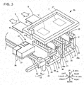
- Fig. 3 is a perspective view illustrating the mask work section 26, the first board fixing section 30, the second board fixing section 40, and the processing section 50, which are configured to perform the printing process and the like of the printing device 20.
- Fig. 1 is a configuration view illustrating an example of a schematic configuration of a mounting system 10 according to one embodiment of the present invention.
- Fig. 2 is an explanatory view illustrating a mask work section 26, a first board fixing section 30, a second board fixing section 40, a processing section 50, and a storage section 60, which are configured to perform
- the mounting system 10 includes the printing device 20 which performs a printing process of solder paste as a viscous fluid on a board S, multiple mounting devices (not illustrated) which mounts electronic components on the board S, and a management computer (PC) 90 which manages information relating to processes by the printing device 20 and the mounting device.
- the printing device 20 is configured as a dual lane printing device having two board fixing sections for fixing conveyed boards S.
- the printing device 20 is configured as a device by which automatic exchanging of a screen mask M used in the printing process and automatic exchanging in which the conveyance jig 80 of the board support member 70 that supports and fixes the board S is used can be performed, when setup changing which changes the printing target to a different type of board S is performed.
- a left-right direction (X-axis), a front-rear direction (Y-axis) and an up-down direction (Z-axis) are as illustrated in Fig. 1 to Fig. 3 .
- the printing device 20 is a device which applies (prints) solder paste on a lower board S via pattern holes 11 and 12 formed on the screen mask M by the solder on the screen mask M pushing into the pattern holes 11 and 12 thereof by using a squeegee 25.
- the printing device 20 includes a control section 21, a printing process section 22, the mask work section 26, the first board fixing section 30, the second board fixing section 40, the processing section 50, and the storage section 60.
- the printing device 20 includes an operation panel on which a display screen is displayed and thus various input operations are possible by an operator and a communication section that performs communication with a device connected to the LAN.
- the control section 21 is configured as a microprocessor centering CPU and includes a ROM that stores process program, a RAM that is used as a work region, an HDD that stores various data, and the like.
- the printing process section 22 is disposed on an upper stage of the printing device 20 and is a unit that performs the printing process of a viscous fluid on the board S by using the screen mask M.
- the printing process section 22 includes a printing head 23, a head moving section 24, the squeegee 25, and a conveyance rod 25a.
- the printing device 20 includes the printing head 23 which pressurizes and supplies solder paste onto a screen mask M.
- the head moving section 24 moves the printing head 23 in a predetermined printing direction (front-rear direction) and includes a guide formed in the front-rear direction, a slider which moves along the guide, and a motor which drives the slider.
- a mechanism which moves the printing head 23 in the up-down direction is also installed in the head moving section 24.
- the squeegee 25 is installed on the printing head 23 so as to be movable in the up-down direction.
- the squeegee 25 is a plate-like member elongated in a predetermined direction (X-direction in Fig. 1 ) and is formed to have a length longer than the pattern holes 11 and 12.
- a conveyance rod 25a is installed on the printing head 23 so as to capable of being lifted and lowered by a motor (not illustrated).
- the conveyance rod 25a pushes and conveys the screen mask M and the conveyance jig 80 in the front and the rear by moving the conveyance rod in the front and the rear by the head moving section 24 in a state of protruding more downward than the squeegee 25.
- the mask work section 26 is a unit that is installed between the printing process section 22, the first board fixing section 30 and the second board fixing section 40 and fixes and holds the screen mask M.
- the screen mask M is, for example, a metal thin plate on which a desired wiring pattern is formed and is fixed to a frame body (mask fixing section 27) with a predetermined tension.
- pattern holes 11 and 12 for forming wiring patterns on the boards S at first and second lanes (first and second board fixing sections 30 and 40) in the printing process are formed, respectively.
- An identification section (for example, a mark) for position recognition is formed on a lower face of the screen mask M.
- the mask work section 26 includes a mask fixing section 27, a position adjustment section 28 (see Fig.
- the mask fixing section 27 positions the screen mask M fitted in the frame body to support and fix the screen mask M in a horizontal posture.
- the position adjustment section 28 adjusts a position the mask fixing section 27 in the XY-directions so that the pattern holes 11 or 12 are disposed at proper positions on the board S fixed to the first board fixing section 30 or the second board fixing section 40.
- a conveyance rail 29 is a pair of left and right rails extending in the front-rear direction and guides the screen mask M and the conveyance jig 80 so that the screen mask and the conveyance jig 80 pushed by the conveyance rod 25a move in the front-rear direction.
- the first board fixing section 30 is a unit which is installed below the mask working section 26, introduces the board S, positions and supports the introduced board S, contacts the board S with the screen mask M on which a predetermined wiring pattern is formed, and separates the board S therefrom.
- the first board fixing section 30 constitutes the first lane of the printing process.
- the first board fixing section 30 includes a board conveyance conveyor 31, a board guide 32, a board guide moving section 33 (see Fig. 4 ), a support table lifting and lowering section 35, a fixing section lifting and lowering section 36, a support table 37, a Y-axis pressing section 38, and a Z-axis clamping section 39. As illustrated in Fig.
- the board conveyance conveyor 31 includes a conveyor belt provided on each of a pair of side frames 30b and a belt revolving device which revolves and drives the conveyor belt.
- an introduction conveyor and a discharge conveyor are installed on an upstream side and the downstream side (left and right sides in Fig. 1 ) on the board conveyance path of the board conveyance conveyor 31, respectively.
- the board guide 32 is a plate-like member provided on the upper face of each of the pair of side frames 30b.
- the board guide moving section 33 is a mechanism which moves the pair of side frames 30b in the front-rear direction to be approached each other and to be separated from each other.
- the board guide moving section also moves the board guide 32 in the front-rear direction and pinches and fixes the board S in a state where an upper face of the board S and an upper face of the board guide 32 are flush with each other.
- the support table lifting and lowering section 35 is a mechanism which lifts and lowers the support table 37 with respect to the main body 30a of the first board fixing section 30 and includes a support column which guides the support table 37 in the up-down direction and a driving motor which moves the support column up and down.
- the support table 37 is a member on which the board support member 70 can be disposed. The board support member 70 is exchanged according to the board S.
- the board support member 70 is a member that is disposed on the support table 37, is connected to a decompression device (not illustrated) by a pipe to suck and fix the board S while supporting the board S from a lower face side thereof by a negative pressure. As illustrated in Fig.
- the board support member 70 includes a main body section 70a, a pair of columnar protruding sections 71 and 71 installed so as to protrude from the left and right of the main body section 70a, a pair of protruding sections 72 and 72 installed forward of the protruding sections 71, multiple suction ports 73 opening on the upper face of the main body section 70a, and a clamped section 74 having an inclined upper face and protruding rearward of the main body section 70a.
- the identification section 75 for example, a mark
- a bar code 76 for recognizing the type of the board support member 70 are formed on the upper face of the main body section 70a.
- the fixing section lifting and lowering section 36 is a mechanism which lifts and lowers the entire first board fixing section 30 with respect to a device main body and includes a support column which guides the main body of the first board fixing section 30 in the up-down direction and supports the main body of the first board fixing section and a driving motor which moves the support column up and down.
- the Y-axis pressing section 38 (see Fig. 2 ) is a mechanism used for the positioning of the board support member 70 and is installed on the support table 37.
- the Y-axis pressing section 38 includes a block-shaped main body which is movable in the front-rear direction and presses and moves the board support member 70 rearward and a driving mechanism such as a cylinder (not illustrated) which moves the main body forward and rearward.
- the Y-axis pressing section 38 also serves as a mechanism for supplying a negative pressure to the board support member 70 and a suction port connected to the decompression device (not illustrated) by a pipe is installed rearward of the main body.
- a path is connected from the decompression device to the suction port 73, and a negative pressure is supplied to the suction port 73.
- the Z-axis clamping section 39 is a mechanism used for fixing the board support member 70 and is installed on the rear side frame 30b.
- the Z-axis clamping section 39 includes a block-shaped main body which can move in the up-down direction and a driving mechanism such as a cylinder for moving the main body up and down.
- the main body of the Z-axis clamping section 39 having moved downward pinches the clamped section 74 of the board support member 70 along with the support table 37 to fix the board support member 70.
- a support plate 39a is installed in the up-down and left-right directions forward of the Z-axis clamping section 39.
- the second board fixing section 40 is a unit which is juxtaposed to the first board fixing section 30 and conveys and fixes the board S like the first board fixing section 30.
- the second board fixing section 40 constitutes the second lane of the printing process.
- the second board fixing section 40 has a main body 40a and a side frame 40b and includes a board conveyance conveyor 41, a board guide 42, a board guide moving section 43, a support table lifting and lowering section 45, a fixing section lifting and lowering section 46, a support table 47, a Y-axis pressing section 48, and a Z-axis clamping section 49.
- the board support member 70 can be disposed on the support table 47.
- the description of the second board fixing section 40 is omitted since the basic configuration thereof is the same as that of the first board fixing section 30.
- the printing device 20 is configured to include two board conveyance devices which are the first board fixing section 30 and the second board fixing section 40 and one mask work section 26.
- the processing section 50 is a unit which performs imaging process of imaging the identification section (for example, a mark and a notch, unevenness, a character, or the like) or the like for position recognition formed on the board S.
- the processing section 50 includes a carriage 51, a processing section moving section 52, and a positional information acquiring section 55.
- the processing section 50 includes a board stopper 56 for stopping the board S conveyed in the right direction by the board conveyance conveyor 31 and 41 at a predetermined position in the left-right direction.
- the positional information acquiring section 55 and the board stopper 56 are installed on the carriage 51 and the carriage 51 moves in the XY-directions by the processing section moving section 52.
- the processing section moving section 52 includes an X-axis slider 53 and a Y-axis slider 54.
- the Y-axis slider 54 is a plate-like member whose longitudinal direction is set as the X-axis direction and is moved along a support rail 58 formed on the device in the Y-axis direction (front-rear direction) by a moving motor.
- the carriage 51 is installed on the X-axis slider 53 and the X-axis slider moves along a guide formed on the Y-axis slider 54 in the X-axis direction by the moving motor.
- the processing section 50 moves to any one of a region (also referred to as a first region) of the first board fixing section 30 which is the first lane, a region (also referred to as a second region) of the second board fixing section 40 which is the second lane, and a retraction region (see Fig. 1 to Fig. 3 ) deviated from the regions.
- the positional information acquiring section 55 is a unit which can image an identification section formed on the board S, an identification section formed on the lower face of the screen mask M, and an identification section 75 of the board support member 70 and acquires positional information thereof by imaging.
- the lower face side and the upper face side of the positional information acquiring section 55 are imaging regions.
- the board stopper 56 is, for example, a rod-like member and is installed on the carriage 51 so as to be capable of lifting and lowering by a motor (not illustrated) .
- the board stopper 56 abuts against the board S conveyed above the board support member 70 by the board conveyance conveyors 31 and 41 to stop the boards S by being in a state where the board stopper 56 protrudes below the support rail 58 above the first and the second board fixing sections 30 and 40.
- the storage section 60 is installed rearward the main body of the printing device 20 and is a mechanism which stores members to be exchanged (to be introduced and to be discharged) during an automatic exchanging of the screen mask M or the board support member 70.
- the storage section 60 includes a storage box with front opening and a conveyor lifting and lowering section 62 which lifts and lowers the storage box. Multiple stages (four stages in the embodiment) of a pair of conveyance conveyors 61 which convey the placed objects in the front-rear direction are installed in the storage box.
- the screen mask M to be introduced into the mask work section 26 a conveyance jig 80 to which the board support members 70 to be introduced into the first and/or the second board fixing sections 30 and/or 40 is attached, and the conveyance jig 80 to which the board support members 70 to be discharged from the first and/or the second board fixing sections 30 and/or 40 is to be attached are stored in three stages of the four stages of conveyance conveyors 61 in advance by the operator. In addition, the remaining one stage of conveyance conveyor 61 is emptied so as to store the screen mask M to be discharged from the mask work section 26.
- the conveyor lifting and lowering section 62 makes the upper face of any conveyance conveyor 61 the same height as the upper face of the conveyance rail 29 and, in the state, the conveyance conveyor 61 is operated so that the storage section 60 introduces a member placed on the conveyance conveyor 61 into the mask work section 26 or discharges a member from the mask work section 26.
- the conveyance jig 80 is a member being capable of conveying the board support member 70 by using the conveyance conveyor 61 and the conveyance rod 25a. As illustrated in Fig. 5 , the conveyance jig 80 has first to fourth protrusion holding sections 81 to 84 installed in this order inside the frame body 85 from the rear toward the front. Each pair of the first to fourth protrusion holding sections 81 to 84 is installed in the left-right direction, respectively and are installed at a tip of an arm section extending downward from the frame body 85. As illustrated in Fig.
- the conveyance jig 80 can attach one board support members 70 thereto by the first and the second protrusion holding sections 81 and 82 and can attach one support member 70 thereto by the third and fourth protrusion holding sections 83 and 84.
- Recessed sections slightly larger than an outer diameter of the protruding sections 71 or the protruding sections 72 of the board support member 70 are formed on the upper faces of the first to fourth protrusion holding sections 81 to 84.
- the conveyance jig 80 has substantially the same width in the left-right direction as that of the mask fixing section 27 of the screen mask M. Accordingly, the conveyance jig 80 can be conveyed along the same conveyance rail 29 as the screen mask M.
- the same storage section 60 can be used for the conveyance jig 80 and the screen mask M, it is preferable that the length of the conveyance jig 80 and the screen mask M in the front-rear direction be close to each other.
- Multiple types of frame bodies 85 or protrusion holding sections having different sizes or the like may be present in the conveyance jig 80 and a bar code 86 for type recognition of the conveyance jig 80 is attached to the upper face of the frame body 85.
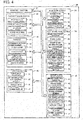
- Fig. 6 is a flowchart illustrating an example of a printing process routine performed by the CPU of the control section 21.
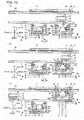
- Fig. 7 to Fig. 9 are explanatory views illustrating states of the exchange processes of the screen mask M or the board support members 70.
- Fig. 10 is an explanatory view illustrating the conveyance, suction, and printing process of the board S.
- the printing process routine is stored in the HDD of the control section 21 and is performed after the operator instructs the printing device 20 for the printing process.
- the CPU of the control section 21 first determines whether or not the exchange processes of the screen mask M present in the mask work section 26 and the board support members 70 present in the first and the second board fixing sections 30 and 40, that is, the setup changing is necessary (step S100).
- the control section 21 determines whether or not it is necessary to change the setup depending on whether or not the screen mask M or the board support member 70 necessary for the printing process are different between the previous time and the current time based on information relating to the printing process acquired from the management PC 90. As illustrated in Fig.
- a screen mask M to be introduced, a conveyance jig 80 to which the board support members 70 to be introduced are attached, and the conveyance jig 80 for attaching the board support members 70 to be discharged thereto are stored in the storage section 60 in advance by the operator.
- the operator reads the bar code 76 or the bar code 86 using a bar code reader as necessary to perform matching whether or not the correct member is stored in the storage section 60.
- the operator adjusts the positions of the second protrusion holding sections 82 and the fourth protrusion holding sections 84 in the front-rear direction in advance with respect to the conveyance jig 80 for attaching the board support members 70 to be discharged thereto.
- the control section 21 performs the mask discharge process of discharging the screen mask M to be discharged from the mask work section 26 (step S110).
- the control section 21 moves the conveyance rod 25a to convey the screen mask M to be discharged present in the mask work section 26 rearward while sliding the screen mask M against the conveyance rail 29 as illustrated in Fig. 7(a) .
- the screen mask M to be discharged is placed on the vacant conveyance conveyor 61. Since it is necessary to discharge the screen mask M in the mask work section 26 once so as to perform the exchange process of the board support member 70, the control section 21 performs the discharge process of the screen mask M even in a case where the screen mask M is not to be exchanged.
- control section 21 performs a support member discharge process of discharging the board support members 70 to be discharged from the first and the second board fixing sections 30 and 40 (step S120).
- control section 21 controls the conveyor lifting and lowering section 62 and the conveyance conveyor 61 to introduce the empty conveyance jig 80 onto the conveyance rail 29 and further moves the conveyance rod 25a forward to convey the conveyance jig 80 above the first and the second board fixing sections 30 and 40 ( Fig. 7(b) ).
- the control section 21 is set so that the first to fourth protrusion holding sections 81 to 84 are positioned to be deviated in the front-rear direction (for example, rearward) from directly above the protruding sections 71 and 72 of the board support members 70. Subsequently, the control section 21 releases the fixing of the board support members 70 on the support tables 37 and 47. Specifically, the control section 21 moves the Y-axis pressing sections 38 and 48 forward, moves the Z-axis clamping sections 39 and 49 upward, and separates the pair of side frames 30b and 40b in the front and the rear by the board guide moving sections 33 and 43 ( Fig. 7(c) ).
- control section 21 lifts the board support members 70 on the support tables 37 and 47 by the support table lifting and lowering sections 35 and 45 and the fixing section lifting and lowering sections 36 and 46, respectively ( Fig. 8(a) ). Accordingly, the protruding sections 71 and 72 of the board support members 70 are lifted above the first to fourth protrusion holding sections 81 to 84.
- control section 21 moves the conveyance jig 80 forward by the conveyance rod 25a so that the first and the second protrusion holding sections 81 and 82 are positioned directly below the protruding sections 71 and 72 of the board support member 70 on the support table 37 and the third and fourth protrusion holding sections 83 and 84 are positioned directly below the protruding sections 71 and 72 of the board support member 70 on the support table 47 ( Fig. 8(b) ).
- the control section 21 lowers the support tables 37 and 47.
- the two board support members 70 are in a state where the protruding sections 71 and 72 are held on the first to fourth protrusion holding sections 81 to 84 and are in a state of being attached to the conveyance jig 80 ( Fig. 8(c) ).
- the control section 21 lowers the entire first and second board fixing sections 30 and 40 by the fixing section lifting and lowering sections 36 and 46 to move the conveyance jig 80 to which the two board support members 70 to be discharged are attached rearward by the conveyance rod 25a ( Fig. 9 ) .
- the control section 21 places the conveyance jig 80 to which the board support members 70 are attached to the conveyance conveyor 61 which is empty as it is.
- the control section 21 combines the conveyance of the conveyance jig 80 in the front and the rear and the lifting and lowering of the support tables 37 and 47 to perform the support member discharge process of the board support members 70.
- the control section 21 After the support member discharge process of step S120, the control section 21 performs a support member introduction process of introducing the board support members 70 to be introduced into the first and the second board fixing sections 30 and 40 (step S130).
- the process can be performed in the reverse order of the support member discharge process described above.
- the control section 21 conveys the conveyance jig 80 to which the two board support members 70 to be introduced are attached forward ( Fig. 9 ), conveys the board support members 70 above the support tables 37 and 47 ( Fig. 8(c) ), and lifts the support tables 37 and 47 to float the protruding sections 71 and 72 from the first to fourth protrusion holding sections 81 to 84 ( Fig. 8(b) ).
- control section 21 moves the conveyance jig 80 rearward ( Fig. 8(a) ) and then lowers the support tables 37 and 47 ( Fig. 7(c) ).
- control section 21 moves the conveyance jig 80 rearward to discharge the conveyance jig 80 and positions and fixes the board support members 70 onto the support tables 37 and 47 ( Fig. 7(b) ).
- the control section 21 causes the pair of side frames 30b and 40b to approach each other in the front and the rear by the board guide moving sections 33 and 43 and to move the support plates 39a and 49a to a predetermined position.
- a position in which the support plates 39a and 49a are moved in the front-rear direction is predetermined according to the type of the board S to be printed or the type of the board support member 70, and the like in advance and is acquired from the management PC 90, for example.
- the control section 21 moves the Y-axis pressing sections 38 and 48 rearward to move the board support members 70 on the support tables 37 and 47 rearward until the board support members 70 are abutted against the support plates 39a and 49a, respectively.
- the board support member 70 can be positioned in a suitable position.
- the control section 21 moves the Z-axis clamping sections 39 and 49 downward to press the clamped section 74 and to fix the position of the board support members 70 on the support tables 37 and 47.
- control section 21 combines conveyance of the conveyance jig 80 in the front and the rear and the lifting and lowering of the support tables 37 and 47 to perform the support member introduction process of the board support members 70. In addition, the control section 21 performs positioning of the board support members 70 in the front-rear direction.
- the control section 21 After the support member discharge process of step S130, the control section 21 performs a mask introduction process of introducing the screen mask M into the mask work section 26 (step S140).
- the control section 21 performs the process in the reverse order of the mask discharge process. In other words, the control section 21 first controls the conveyor lifting and lowering section 62 and the conveyance conveyor 61 to convey the screen mask M to be conveyed to the conveyance rail 29, and moves the screen mask M forward by the conveyance rod 25a to introduce the screen mask into the mask work section 26. In a case where the screen mask M is not to be exchanged, the screen mask M discharged in the mask discharge process is introduced.
- the control section 21 acquires positional information of the introduced board support member 70 in the left-right direction (step S150), and determines the correction value of the stopping position of the board S based on the acquired positional information (step S160).
- the control section 21 moves the carriage 51 above the support table 37 as illustrated in Fig. 10(a) and causes the positional information acquiring section 55 to image the identification section 75 on the upper face of the board support member 70.
- the control section 21 Based on the position of the identification section 75 in the image acquired from the positional information acquiring section 55, the control section 21 obtains the positional deviation of the board support member 70 on the support table 37 in the left-right direction (conveyance direction of board S), derives a correction value of the stopping position at the time of conveying the board S to store the correction value in the RAM or the like.
- the board support member 70 deviates in the conveyance direction of the board S on the support table 37, there is a case where a problem occurs in suction fixing of the board S depending on the stopping position of the board S.
- control section 21 In a case where the position of the board support member 70 deviates in the left-right direction, the control section 21 also corrects the stopping position of the board S by the deviated amount so that the positional relationship between the board support member 70 and the board S is unchanged.
- the control section 21 similarly performs acquisition of positional information and derivation of the correction value for the board support member 70 on the support table 47.
- the control section 21 drives the board conveyance conveyor 31 to convey the board S to the first board fixing section 30 (first lane) to suck the board S to the board support member 70 (step S170).
- the control section 21 moves the carriage 51 in the front and the rear, and in the left and the right and lowers the board stopper 56 so that the board S conveyed to left and right is stopped at a predetermined stopping position on the board support member 70 ( Fig. 10(b) ).
- the board stopper 56 is moved to the position where the correction value is added.
- the control section 21 lifts the support table 37 to abut the upper face of the board support member 70 against the lower face of the stopped board S and to suck and fix the board S by a negative pressure from the decompression device.
- control section 21 performs an imaging process of the identification sections of the board S and the screen mask M by the positional information acquiring section 55 (step S180), and the positions of the board S and the pattern holes 11 of the screen mask M are adjusted so as to be in the proper position based on the obtained image (step S190) .
- the control section 21 starts printing on the first board fixing section 30 (step S200, Fig. 10(c) ).
- the control section 21 lifts the first board fixing section 30 so as to be abutted against the upper face of the board S and the lower face of the screen mask M.
- the printing head 23 is moved onto the screen mask M on the first lane side, the solder paste is pressurized and discharged from the printing head 23, the squeegee 25 is moved in the front and the rear to print the solder paste on the board S.
- the control section 21 determines whether or not the production process is completed based on whether or not there is the board S on which to print next (step S210) .
- the conveyance of the board S, the positional adjustment of the screen mask M, the printing process, or the like is performed by using the second board fixing section 40 (steps S220 to S250). Since the process is the same as the process (steps S170 to S200) in the first board fixing section 30 described above, a detailed description thereof will be omitted.
- the control section 21 determines whether or not the production is completed (step S260) and when the production is not completed, the control section 21 performs the process of shifting to step S100. In other words, while performing the setup change if necessary, the printing process on the boards S fixed to the first and the second board fixing sections 30 and 40 is sequentially performed.
- the control section 21 ends the present routine.
- the conveyance rod 25a of the embodiment corresponds to a support member conveyance section of the invention and the control section 21 corresponds to an exchange control section.
- the first and the second board fixing sections 30 and 40 correspond to the board fixing section
- the Y-axis pressing sections 38 and 48, the board guide moving sections 33 and 43, and the support plates 39a and 49a correspond to the positioning section
- the board conveyance conveyors 31 and 41 correspond to the board conveyance section
- the positional information acquiring section 55 corresponds to the positional information acquiring section
- the control section 21 and the board stopper 56 correspond to the correction section
- the support tables 37 and 47 correspond to the support table
- the support table lifting and lowering sections 35 and 45 and the fixing section lifting and lowering sections 36 and 46 correspond to the support member lifting and lowering section
- the conveyance jig 80 corresponds to the conveyance jig.
- the printing device 20 includes a support member conveyance section (conveyance rod 25a) for discharging and introducing the screen mask M and the board support member 70.
- the support member exchange process steps S120 and S130
- the automatic exchanging of the board support member 70 can be performed.
- the printing device 20 can also perform a mask exchange process (steps S110 and S140) for performing the discharge and the introduction of the screen mask M.
- automatic exchanging of the board support member 70 and automatic exchanging of the screen mask M can be performed using the same conveyance rod 25a. Therefore, for example, the configuration of the device can be made more compact compared to a case where the printing device 20 separately includes the conveyance section for exchanging the screen mask and the conveyance section for exchanging the board support member.
- the board support member 70 can be disposed on the printing device 20, and the printing device 20 includes the first and/or the second board fixing sections 30 and/or 40 which fix the board S by the disposed board support member 70 when the printing process is performed, the positioning sections (Y-axis pressing sections 38 and/or 48, board guide moving sections 33 and/or 43, and supporting plates 39a and/or 49a) which perform the positioning of the board support member 70 in the horizontal direction by moving the board support member 70 disposed on the first and/or the second board fixing sections 30 and/or 40.
- the positioning sections Y-axis pressing sections 38 and/or 48, board guide moving sections 33 and/or 43, and supporting plates 39a and/or 49a
- control section 21 controls the conveyance rod 25a to convey the board support member 70 to be introduced to the first and/or the second board fixing sections 30 and/or 40 and controls the Y-axis pressing sections 38 and/or 48, the board guide moving sections 33 and/or 43, and the support plates 39a and/or 49a to perform the positioning of the conveyed board support member 70 in the front-rear direction. Therefore, positional deviation can be suppressed in the first and/or the second board fixing sections 30 and/or 40 of the board support member 70 conveyed in the support member introduction process in the front-rear direction.
- the printing device 20 includes the first and/or the second board fixing sections 30 and/or 40, the board conveyance conveyors 31 and/or 41 which convey the board S in a predetermined board conveyance direction (left-right direction), and a positional information acquiring section 55 which acquires positional information on the position of the board support member 70 disposed on the first and/or the second board fixing sections 30 and/or 40 in the board conveyance direction.
- the printing device 20 includes the correction section (control section 21 and board stopper 56) which corrects the stopping position on the board support member 70 based on the acquired positional information when the board conveyance conveyor 31 and/or 41 convey the board S.
- the stopping position of the board S can be corrected based on the positional information. Therefore, the occurrence of problems in fixing the board S by the board support member 70 can be suppressed.
- the printing device 20 has the support tables 37 and/or 47 on which the board support member 70 can be disposed and includes the first and/or the second board fixing sections 30 and/or 40 which fix the board S by the disposed board support member 70 when the printing process is performed, the support table lifting and lowering sections 35 and/or 45 which lift and lower the board support member 70 disposed on the support tables 37 and/or 47 by lifting and lowering the support tables 37 and/or 47, and the fixing section lifting and lowering sections 36 and/or 46.
- the conveyance rod 25a discharges and introduces a conveyance jig 80 to which the board support member 70 can be attached, and in a support member discharge process, the control section 21 controls the conveyance rod 25a, the support table lifting and lowering sections 35 and/or 45, and the fixing section lifting and lowering sections 36 and/or 46 to convey the conveyance jig 80 above the first and/or the second board fixing sections 30 and/or 40, to lift the board support member 70 to be discharged disposed on the support tables 37 and/or 38, to be attached to the conveyance jig 80, and to perform the process of discharging conveyance jig 80 after the attachment.
- control section 21 controls the conveyance rod 25a, the support table lifting and lowering sections 35 and/or 45, and the fixing section lifting and lowering sections 36 and/or 46 to convey the conveyance jig 80 to which the board support member 70 to be introduced is attached above the first and/or the second board fixing sections 30 and/or 40 and lifts the support tables 37 and/or 47 to detach the board support member 70 to be introduced from the conveyance jig 80, to dispose the board support member on the support tables 37 and/or 47, and to perform the process of discharging the conveyance jig 80 after the detachment.
- the support member exchange process can be performed by conveying the board support member 70 by using the conveyance jig 80.
- the conveyance rod 25a conveys the screen mask M and the board support member 70 together
- the width of the board support member 70 in the left-right direction is smaller than that of the screen mask M
- the board support member 70 cannot be conveyed directly by the conveyance rod 25a by sliding on the conveyance rail 29.
- the printing device 20 has the first board fixing section 30 and the second board fixing section 40 as a board fixing section and has the first support member lifting and lowering section (support table lifting and lowering section 35 and fixing section lifting and lowering section 36) which lifts and lowers the support table 37 and the second support member lifting and lowering section (support table lifting and lowering section 45 and fixing section lifting and lowering section 46) which lifts and lowers the support table 47, as a support member lifting and lowering section.
- the conveyance rod 25a discharges and introduces the conveyance jig 80 which can attach multiple the board support members 70 thereto.
- control section 21 controls the conveyance rod 25a, the support table lifting and lowering sections 35 and 45, and the fixing section lifting and lowering sections 36 and 46 to introduce the conveyance jig 80, to lift each of the board support members 70 to be discharged disposed on the support tables 37 and 47, to attach the board support members to the conveyance jig 80, and to perform the process of conveying the conveyance jig 80 after the attachment.
- control section 21 controls the conveyance rod 25a, the support table lifting and lowering sections 35 and 45, and the fixing section lifting and lowering sections 36 and 46 to introduce the conveyance jig 80 to which the board support members 70 to be introduced and disposed on the support table 37 and the support table 47 respectively are attached, to lift the support tables 37 and 47, to detach each board support member 70 to be introduced from the conveyance jig 80, to dispose each of the board support members 70 on the support tables 37 and 47 respectively, and to perform a process of discharging the conveyance jig 80 after the detachment.
- control section 21 performs the exchange of the board support member 70 disposed on the support table 37 and the exchange of the board support member 70 disposed on the support table 47 in parallel.
- the board support members 70 to be discharged disposed on the support tables 37 and 47 can be discharged together by the discharge of the conveyance jig 80 once and the board support members 70 to be introduced which are to be disposed on the support tables 37 and 47 can be introduced together by the introduction of the conveyance jig 80 once, the time required for the support member exchange process can be shortened.
- control section 21 performs the exchange of the board support member 70 disposed on the support table 37 and the exchange of the board support member 70 disposed on the support table 47 in parallel using the conveyance jig 80 which can attach two board support members 70 thereto
- the invention is not limited thereto.
- only one of the board support members 70 on the support tables 37 or 47 may be exchanged.
- the control section 21 may perform the support member introduction process and the support member discharge process in parallel.
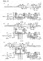
- Fig. 11 is an explanatory view illustrating a state where the support member introduction process and the support member discharge process are performed in parallel.
- a case where the board support member 70 of the second board fixing section 40 is exchanged will be described.
- control section 21 conveys the conveyance jig 80 to which the board support member 70 to be introduced is attached above the second board fixing section 40 ( Fig. 11(a) ). Subsequently, the control section 21 lifts the board support member 70 to be discharged disposed on the support table 47 to attach the board support member 70 to the conveyance jig 80 ( Fig. 11(b) ). Next, after the attachment, the control section 21 further conveys the conveyance jig 80 forward to convey the board support member 70 to be introduced above the support table 47, to lift the support table 47 to detach the board support member 70 to be introduced from the conveyance jig 80 and to dispose the board support member on the support table 47 ( Fig. 11(c) ).
- the control section 21 discharges the conveyance jig 80 after the detachment (conveyance jig 80 to which the board support member 70 to be discharged is attached) rearward. By doing so, the discharge and the introduction of the board support member 70 can be performed by discharging and introducing the conveyance jig 80 once. Therefore, the time required for the support member exchange process can be shortened.
- the printing device 20 can discharge and introduce the screen mask M and the board support member 70 together by using the conveyance rod 25a
- the invention is not limited thereto.
- At least the board support member exchange process can be performed as long as the invention includes a support member conveyance section which performs the discharging and the introduction of the board support member 70.
- the board support members 70 disposed on the first and/or the second board fixing sections 30 and/or 40 and performing the positioning of the board support members in the horizontal direction an effect of suppressing positional deviation in the first and/or the second board fixing sections 30 and/or 40 of the board support members 70 in the front-rear direction can be obtained.
- the printing device 20 that performs exchange of the board support member 70 is described, it is not limited to the printing device as long as it performs the board support member exchange process .
- the invention can be applied to a board work device that performs a board work on a board fixed on a board support member.
- a board work device other than the printing device for example, a mounting device that performs a component mounting process on a board can be included, as an example.
- the printing device 20 includes the conveyance rod 25a as a support member conveyance section, as long as the support member conveyance section can perform the discharge and the introduction of the board support member 70, any support member conveyance section may be provided.
- the support member conveyance section may be a support member conveyance conveyor including a conveyor belt and a belt revolving device that revolves and drives the conveyor belt.
- the conveyance jig 80 may not be used if the board support member 70 can be conveyed by using the conveyance rail 29 and the conveyance rod 25a.
- the Y-axis pressing section 38, the board guide moving section 33, and the support plate 39a are used to perform the positioning of the board support member 70 in the front-rear direction
- the invention is not limited thereto as long as the positioning is performed in the horizontal direction.
- the positioning in the left-right direction may be performed in addition to or in place of the positioning in the front-rear direction.
- the protruding sections 71 and 72 of the board support member 70 are formed in a cylindrical column shape
- the protruding sections are not limited thereto as long as the protruding sections can be attached to and detached from the conveyance jig 80.
- the protruding section may have a square prism shape, a plate shape, or one member in which two cylindrical columns are adjacent to each other.
- the number of the protruding sections is also two in left and light, the number of the protruding sections is not limited thereto, one or three or more protruding sections may be provided on each of the left and right.
- the protrusion holding section is not limited thereto as long as the protrusion holding section can attach and detach the protruding sections 71 and 72 to and from the conveyance jig 80.
- the conveyance jig 80 includes a pair of plate-like members protruding inside the frame body 85, and the protruding sections 71 and 72 are placed on the upper face of the plate-like members, whereby attachment of the board support member 70 to the conveyance jig 80 may be performed.
- the conveyance jig 80 may include a plate-like member moving mechanism which includes a button that can be pushed downward, a lever that rotates around its axis by lowering the button and converts movement in the up-down direction into movement in the left-right direction , and a plate-like member that moves in the left-right direction according to the rotation of the lever.
- the board support member 70 is placed on the plate-shaped member of a pair of front and rear plate-like member moving mechanisms and is conveyed, and for example, the buttons of the pair of plate-like member moving mechanisms are pushed down by the conveyance rod 25a or the like to separate the pair of plate-like members in left and right and thus may detach the board support member 70 from the conveyance jig 80.
- the operation of conveying the conveyance jig 80 in the front and the rear is not necessary when the board support member 70 is detached from the conveyance jig 80.
- the printing device 20 includes the storage section 60, the printing device 20 may not include the storage section 60.
- the printing device 20 is a dual lane printing device having the first and the second board fixing sections 30 and 40, the printing device is not limited thereto.
- the printing device 20 may be a single lane printing device having one board fixing section.
- the board support member 70 is a member that sucks and fixes the board S while supporting the board S from the lower face side by negative pressure
- the board support member may be any member as long as the board support member fixes the board.
- the board support member includes multiple protruding sections (backup pins) erected on the upper face and the board support member may support and fix the board S from below by the protruding section.
- the present invention can be used in a board work device that performs a board work on a board, such as a mounting device for mounting components on a board and a printing device related to the mounting device.
Applications Claiming Priority (1)
| Application Number | Priority Date | Filing Date | Title |
|---|---|---|---|
| PCT/JP2015/066526 WO2016199207A1 (ja) | 2015-06-08 | 2015-06-08 | 印刷装置及び対基板作業装置 |
Publications (3)
| Publication Number | Publication Date |
|---|---|
| EP3305525A4 EP3305525A4 (de) | 2018-04-11 |
| EP3305525A1 true EP3305525A1 (de) | 2018-04-11 |
| EP3305525B1 EP3305525B1 (de) | 2021-09-08 |
Family
ID=57504871
Family Applications (1)
| Application Number | Title | Priority Date | Filing Date |
|---|---|---|---|
| EP15894892.7A Active EP3305525B1 (de) | 2015-06-08 | 2015-06-08 | Druckvorrichtung |
Country Status (5)
| Country | Link |
|---|---|
| US (2) | US10589514B2 (de) |
| EP (1) | EP3305525B1 (de) |
| JP (1) | JP6659682B2 (de) |
| CN (1) | CN107709014B (de) |
| WO (1) | WO2016199207A1 (de) |
Cited By (5)
| Publication number | Priority date | Publication date | Assignee | Title |
|---|---|---|---|---|
| EP3725523A1 (de) * | 2019-04-18 | 2020-10-21 | Exentis Knowledge GmbH | Vorrichtung und verfahren zur herstellung von dreidimensionalen siebdruckwerkstücken |
| EP3725525A1 (de) * | 2019-04-18 | 2020-10-21 | Exentis Knowledge GmbH | Vorrichtung und verfahren zur herstellung von dreidimensionalen siebdruckwerkstücken |
| EP3725524A1 (de) * | 2019-04-18 | 2020-10-21 | Exentis Knowledge GmbH | Vorrichtung und verfahren zur herstellung von dreidimensionalen siebdruckwerkstücken |
| CN112154069A (zh) * | 2018-05-25 | 2020-12-29 | 株式会社富士 | 收纳装置及印刷系统 |
| AU2020257519B2 (en) * | 2019-04-18 | 2023-11-23 | Exentis Knowledge Gmbh | Apparatus and method for the production of three-dimensional screen-printed workpieces |
Families Citing this family (13)
| Publication number | Priority date | Publication date | Assignee | Title |
|---|---|---|---|---|
| JP6786628B2 (ja) * | 2016-12-26 | 2020-11-18 | 株式会社Fuji | スクリーン印刷機 |
| JP6496912B2 (ja) * | 2017-01-30 | 2019-04-10 | パナソニックIpマネジメント株式会社 | スクリーン印刷装置及びスクリーン印刷方法 |
| WO2019138464A1 (ja) * | 2018-01-10 | 2019-07-18 | ヤマハ発動機株式会社 | スクリーン印刷装置 |
| CN109501451B (zh) * | 2018-11-13 | 2020-12-22 | 浙江东方职业技术学院(浙江东方专修学院) | 一种印刷机用刮刀分离装置 |
| CN109594048B (zh) * | 2019-01-30 | 2021-01-01 | 深圳市华星光电半导体显示技术有限公司 | 金属溅镀机 |
| CN110001055A (zh) * | 2019-04-01 | 2019-07-12 | 共享智能铸造产业创新中心有限公司 | 3d打印设备及3d打印方法 |
| EP3725526A1 (de) * | 2019-04-18 | 2020-10-21 | Exentis Knowledge GmbH | Verfahren zur herstellung von dreidimensionalen siebdruckwerkstücken |
| CN110216979B (zh) * | 2019-05-28 | 2020-11-10 | 铜陵金基科技有限公司 | 一种带有辅助夹持装置的smt印刷机构 |
| WO2021214898A1 (ja) * | 2020-04-22 | 2021-10-28 | 株式会社Fuji | 印刷機および印刷システム |
| CN117241945A (zh) * | 2021-05-07 | 2023-12-15 | 株式会社富士 | 输送夹具及作业装置 |
| CN117203057A (zh) * | 2021-05-07 | 2023-12-08 | 株式会社富士 | 搬运夹具及支撑部件以及作业装置 |
| DE112021007617T5 (de) | 2021-05-07 | 2024-02-29 | Fuji Corporation | Arbeitsvorrichtung |
| WO2023095221A1 (ja) * | 2021-11-24 | 2023-06-01 | 株式会社Fuji | 収容ラック、交換フレーム、ラックシステム及び印刷装置 |
Family Cites Families (13)
| Publication number | Priority date | Publication date | Assignee | Title |
|---|---|---|---|---|
| JP2861332B2 (ja) * | 1990-08-28 | 1999-02-24 | 松下電器産業株式会社 | スクリーン印刷装置 |
| JP2889692B2 (ja) * | 1990-11-29 | 1999-05-10 | 三洋電機株式会社 | スクリーン印刷機 |
| JP3170862B2 (ja) * | 1992-05-07 | 2001-05-28 | 松下電器産業株式会社 | スクリーン印刷装置 |
| JP4793987B2 (ja) * | 2006-03-15 | 2011-10-12 | 富士機械製造株式会社 | スクリーン印刷方法及びスクリーン印刷装置 |
| JP4356769B2 (ja) * | 2007-05-22 | 2009-11-04 | パナソニック株式会社 | スクリーン印刷装置およびスクリーン印刷方法 |
| JP5276396B2 (ja) * | 2008-09-25 | 2013-08-28 | 富士機械製造株式会社 | スクリーン印刷装置 |
| JP2011031588A (ja) * | 2009-08-06 | 2011-02-17 | Panasonic Corp | スクリーン印刷装置およびスクリーン印刷方法 |
| JP5723221B2 (ja) * | 2011-05-31 | 2015-05-27 | ヤマハ発動機株式会社 | スクリーン印刷装置 |
| JP5829494B2 (ja) * | 2011-11-14 | 2015-12-09 | 富士機械製造株式会社 | マスク印刷方法および装置 |
| JP5857190B2 (ja) * | 2012-04-17 | 2016-02-10 | パナソニックIpマネジメント株式会社 | 電子部品実装システム |
| CN203338870U (zh) * | 2013-07-03 | 2013-12-11 | 南昌欧菲光科技有限公司 | 制备导电膜治具及导电膜制备装置 |
| JP6833865B2 (ja) * | 2016-10-13 | 2021-02-24 | 株式会社Fuji | スクリーン印刷機 |
| JP7029587B2 (ja) * | 2017-10-19 | 2022-03-04 | パナソニックIpマネジメント株式会社 | スクリーン印刷装置およびスクリーン印刷方法 |
-
2015
- 2015-06-08 JP JP2017522777A patent/JP6659682B2/ja active Active
- 2015-06-08 EP EP15894892.7A patent/EP3305525B1/de active Active
- 2015-06-08 CN CN201580080718.9A patent/CN107709014B/zh active Active
- 2015-06-08 WO PCT/JP2015/066526 patent/WO2016199207A1/ja active Application Filing
- 2015-06-08 US US15/580,522 patent/US10589514B2/en active Active
-
2020
- 2020-02-20 US US16/796,218 patent/US11007768B2/en active Active
Cited By (13)
| Publication number | Priority date | Publication date | Assignee | Title |
|---|---|---|---|---|
| CN112154069A (zh) * | 2018-05-25 | 2020-12-29 | 株式会社富士 | 收纳装置及印刷系统 |
| EP3804993A4 (de) * | 2018-05-25 | 2021-04-21 | Fuji Corporation | Speichervorrichtung und drucksystem |
| WO2020212370A1 (de) * | 2019-04-18 | 2020-10-22 | Exentis Knowledge Gmbh | Vorrichtung und verfahren zur herstellung von dreidimensionalen siebdruckwerkstücken |
| EP3725523A1 (de) * | 2019-04-18 | 2020-10-21 | Exentis Knowledge GmbH | Vorrichtung und verfahren zur herstellung von dreidimensionalen siebdruckwerkstücken |
| WO2020212369A1 (de) * | 2019-04-18 | 2020-10-22 | Exentis Knowledge Gmbh | Vorrichtung und verfahren zur herstellung von dreidimensionalen siebdruckwerkstücken |
| WO2020212368A1 (de) * | 2019-04-18 | 2020-10-22 | Exentis Knowledge Gmbh | Vorrichtung und verfahren zur herstellung von dreidimensionalen siebdruckwerkstücken |
| EP3725524A1 (de) * | 2019-04-18 | 2020-10-21 | Exentis Knowledge GmbH | Vorrichtung und verfahren zur herstellung von dreidimensionalen siebdruckwerkstücken |
| EP3725525A1 (de) * | 2019-04-18 | 2020-10-21 | Exentis Knowledge GmbH | Vorrichtung und verfahren zur herstellung von dreidimensionalen siebdruckwerkstücken |
| CN113840732A (zh) * | 2019-04-18 | 2021-12-24 | 埃克森蒂斯知识股份有限公司 | 用于生产三维丝网印刷工件的设备和方法 |
| AU2020259078B2 (en) * | 2019-04-18 | 2023-10-12 | Exentis Knowledge Gmbh | Apparatus and method for the production of three-dimensional screen-printed workpieces |
| AU2020257519B2 (en) * | 2019-04-18 | 2023-11-23 | Exentis Knowledge Gmbh | Apparatus and method for the production of three-dimensional screen-printed workpieces |
| AU2020259973B2 (en) * | 2019-04-18 | 2023-11-23 | Exentis Knowledge Gmbh | Apparatus and method for the production of three-dimensional screen-printed workpieces |
| CN113840732B (zh) * | 2019-04-18 | 2024-02-09 | 埃克森蒂斯知识股份有限公司 | 用于生产三维丝网印刷工件的设备和方法 |
Also Published As
| Publication number | Publication date |
|---|---|
| EP3305525A4 (de) | 2018-04-11 |
| US11007768B2 (en) | 2021-05-18 |
| WO2016199207A1 (ja) | 2016-12-15 |
| US10589514B2 (en) | 2020-03-17 |
| JP6659682B2 (ja) | 2020-03-04 |
| EP3305525B1 (de) | 2021-09-08 |
| US20180162118A1 (en) | 2018-06-14 |
| CN107709014B (zh) | 2020-03-06 |
| CN107709014A (zh) | 2018-02-16 |
| US20200189261A1 (en) | 2020-06-18 |
| JPWO2016199207A1 (ja) | 2018-03-22 |
Similar Documents
| Publication | Publication Date | Title |
|---|---|---|
| US11007768B2 (en) | Board work device having support member conveyance section for conveying board support member | |
| JP6898248B2 (ja) | ステンシルプリンターのためのリフトツールアセンブリ | |
| JP6744426B2 (ja) | 印刷装置及び収納装置 | |
| EP3527374B1 (de) | Siebdruckmaschine | |
| CN106413372B (zh) | 搬运装置 | |
| JP4866231B2 (ja) | バックアップピンの回収方法、バックアップピンの供給方法、作業用治具、基板支持装置、表面実装機、クリーム半田印刷装置、及び基板検査装置 | |
| JP6965273B2 (ja) | 印刷装置 | |
| JP2008114521A (ja) | スクリーン印刷装置およびスクリーン印刷装置における下受交換作業方法 | |
| JP7113989B2 (ja) | 対基板作業装置 | |
| JP7033155B2 (ja) | 対基板作業装置 | |
| JP7436608B2 (ja) | 印刷システム | |
| JP2010143085A (ja) | 基板支持装置及びスクリーン印刷機 | |
| JP2009135215A (ja) | 基板位置決め装置及び基板位置決め方法 | |
| WO2017187513A1 (ja) | 基板サポート装置、スクリーン印刷装置、塗布装置、表面実装機、及び、バックアップピン段取り方法 | |
| JP7353436B2 (ja) | 印刷装置 | |
| CN110997328B (zh) | 丝网印刷机 | |
| JP5370229B2 (ja) | 電子部品実装用装置及び電子部品実装用装置による作業方法 | |
| JP6824880B2 (ja) | 印刷装置 | |
| JP2012074637A (ja) | 支持ピンの段取り替え方法 |
Legal Events
| Date | Code | Title | Description |
|---|---|---|---|
| STAA | Information on the status of an ep patent application or granted ep patent |
Free format text: STATUS: THE INTERNATIONAL PUBLICATION HAS BEEN MADE |
|
| PUAI | Public reference made under article 153(3) epc to a published international application that has entered the european phase |
Free format text: ORIGINAL CODE: 0009012 |
|
| STAA | Information on the status of an ep patent application or granted ep patent |
Free format text: STATUS: REQUEST FOR EXAMINATION WAS MADE |
|
| 17P | Request for examination filed |
Effective date: 20171208 |
|
| A4 | Supplementary search report drawn up and despatched |
Effective date: 20180302 |
|
| AK | Designated contracting states |
Kind code of ref document: A1 Designated state(s): AL AT BE BG CH CY CZ DE DK EE ES FI FR GB GR HR HU IE IS IT LI LT LU LV MC MK MT NL NO PL PT RO RS SE SI SK SM TR |
|
| AX | Request for extension of the european patent |
Extension state: BA ME |
|
| DAV | Request for validation of the european patent (deleted) | ||
| DAX | Request for extension of the european patent (deleted) | ||
| RAP1 | Party data changed (applicant data changed or rights of an application transferred) |
Owner name: FUJI CORPORATION |
|
| RIN1 | Information on inventor provided before grant (corrected) |
Inventor name: KUSUNOKI, KAZUHIRO Inventor name: KAMEGAI, YASUNORI Inventor name: HIRUKAWA, RITSUO Inventor name: MIZUKOSHI, TSUYOSHI Inventor name: TORII, ATSUSHI Inventor name: IISAKA, JUN Inventor name: KONDO, TAKESHI Inventor name: KATO, MITSUAKI |
|
| GRAP | Despatch of communication of intention to grant a patent |
Free format text: ORIGINAL CODE: EPIDOSNIGR1 |
|
| STAA | Information on the status of an ep patent application or granted ep patent |
Free format text: STATUS: GRANT OF PATENT IS INTENDED |
|
| INTG | Intention to grant announced |
Effective date: 20210514 |
|
| RIN1 | Information on inventor provided before grant (corrected) |
Inventor name: KUSUNOKI, KAZUHIRO Inventor name: IISAKA, JUN Inventor name: TORII, ATSUSHI Inventor name: MIZUKOSHI, TSUYOSHI Inventor name: KATO, MITSUAKI Inventor name: KONDO, TAKESHI Inventor name: KAMEGAI, YASUNORI Inventor name: HIRUKAWA, RITSUO |
|
| GRAS | Grant fee paid |
Free format text: ORIGINAL CODE: EPIDOSNIGR3 |
|
| GRAA | (expected) grant |
Free format text: ORIGINAL CODE: 0009210 |
|
| STAA | Information on the status of an ep patent application or granted ep patent |
Free format text: STATUS: THE PATENT HAS BEEN GRANTED |
|
| AK | Designated contracting states |
Kind code of ref document: B1 Designated state(s): AL AT BE BG CH CY CZ DE DK EE ES FI FR GB GR HR HU IE IS IT LI LT LU LV MC MK MT NL NO PL PT RO RS SE SI SK SM TR |
|
| REG | Reference to a national code |
Ref country code: GB Ref legal event code: FG4D |
|
| REG | Reference to a national code |
Ref country code: CH Ref legal event code: EP Ref country code: AT Ref legal event code: REF Ref document number: 1428243 Country of ref document: AT Kind code of ref document: T Effective date: 20210915 |
|
| REG | Reference to a national code |
Ref country code: DE Ref legal event code: R096 Ref document number: 602015073205 Country of ref document: DE |
|
| REG | Reference to a national code |
Ref country code: IE Ref legal event code: FG4D |
|
| REG | Reference to a national code |
Ref country code: LT Ref legal event code: MG9D |
|
| REG | Reference to a national code |
Ref country code: NL Ref legal event code: MP Effective date: 20210908 |
|
| PG25 | Lapsed in a contracting state [announced via postgrant information from national office to epo] |
Ref country code: LT Free format text: LAPSE BECAUSE OF FAILURE TO SUBMIT A TRANSLATION OF THE DESCRIPTION OR TO PAY THE FEE WITHIN THE PRESCRIBED TIME-LIMIT Effective date: 20210908 Ref country code: BG Free format text: LAPSE BECAUSE OF FAILURE TO SUBMIT A TRANSLATION OF THE DESCRIPTION OR TO PAY THE FEE WITHIN THE PRESCRIBED TIME-LIMIT Effective date: 20211208 Ref country code: FI Free format text: LAPSE BECAUSE OF FAILURE TO SUBMIT A TRANSLATION OF THE DESCRIPTION OR TO PAY THE FEE WITHIN THE PRESCRIBED TIME-LIMIT Effective date: 20210908 Ref country code: ES Free format text: LAPSE BECAUSE OF FAILURE TO SUBMIT A TRANSLATION OF THE DESCRIPTION OR TO PAY THE FEE WITHIN THE PRESCRIBED TIME-LIMIT Effective date: 20210908 Ref country code: NO Free format text: LAPSE BECAUSE OF FAILURE TO SUBMIT A TRANSLATION OF THE DESCRIPTION OR TO PAY THE FEE WITHIN THE PRESCRIBED TIME-LIMIT Effective date: 20211208 Ref country code: RS Free format text: LAPSE BECAUSE OF FAILURE TO SUBMIT A TRANSLATION OF THE DESCRIPTION OR TO PAY THE FEE WITHIN THE PRESCRIBED TIME-LIMIT Effective date: 20210908 Ref country code: SE Free format text: LAPSE BECAUSE OF FAILURE TO SUBMIT A TRANSLATION OF THE DESCRIPTION OR TO PAY THE FEE WITHIN THE PRESCRIBED TIME-LIMIT Effective date: 20210908 Ref country code: HR Free format text: LAPSE BECAUSE OF FAILURE TO SUBMIT A TRANSLATION OF THE DESCRIPTION OR TO PAY THE FEE WITHIN THE PRESCRIBED TIME-LIMIT Effective date: 20210908 |
|
| REG | Reference to a national code |
Ref country code: AT Ref legal event code: MK05 Ref document number: 1428243 Country of ref document: AT Kind code of ref document: T Effective date: 20210908 |
|
| PG25 | Lapsed in a contracting state [announced via postgrant information from national office to epo] |
Ref country code: LV Free format text: LAPSE BECAUSE OF FAILURE TO SUBMIT A TRANSLATION OF THE DESCRIPTION OR TO PAY THE FEE WITHIN THE PRESCRIBED TIME-LIMIT Effective date: 20210908 Ref country code: GR Free format text: LAPSE BECAUSE OF FAILURE TO SUBMIT A TRANSLATION OF THE DESCRIPTION OR TO PAY THE FEE WITHIN THE PRESCRIBED TIME-LIMIT Effective date: 20211209 |
|
| PG25 | Lapsed in a contracting state [announced via postgrant information from national office to epo] |
Ref country code: AT Free format text: LAPSE BECAUSE OF FAILURE TO SUBMIT A TRANSLATION OF THE DESCRIPTION OR TO PAY THE FEE WITHIN THE PRESCRIBED TIME-LIMIT Effective date: 20210908 |
|
| PG25 | Lapsed in a contracting state [announced via postgrant information from national office to epo] |
Ref country code: IS Free format text: LAPSE BECAUSE OF FAILURE TO SUBMIT A TRANSLATION OF THE DESCRIPTION OR TO PAY THE FEE WITHIN THE PRESCRIBED TIME-LIMIT Effective date: 20220108 Ref country code: SM Free format text: LAPSE BECAUSE OF FAILURE TO SUBMIT A TRANSLATION OF THE DESCRIPTION OR TO PAY THE FEE WITHIN THE PRESCRIBED TIME-LIMIT Effective date: 20210908 Ref country code: SK Free format text: LAPSE BECAUSE OF FAILURE TO SUBMIT A TRANSLATION OF THE DESCRIPTION OR TO PAY THE FEE WITHIN THE PRESCRIBED TIME-LIMIT Effective date: 20210908 Ref country code: RO Free format text: LAPSE BECAUSE OF FAILURE TO SUBMIT A TRANSLATION OF THE DESCRIPTION OR TO PAY THE FEE WITHIN THE PRESCRIBED TIME-LIMIT Effective date: 20210908 Ref country code: PT Free format text: LAPSE BECAUSE OF FAILURE TO SUBMIT A TRANSLATION OF THE DESCRIPTION OR TO PAY THE FEE WITHIN THE PRESCRIBED TIME-LIMIT Effective date: 20220110 Ref country code: PL Free format text: LAPSE BECAUSE OF FAILURE TO SUBMIT A TRANSLATION OF THE DESCRIPTION OR TO PAY THE FEE WITHIN THE PRESCRIBED TIME-LIMIT Effective date: 20210908 Ref country code: NL Free format text: LAPSE BECAUSE OF FAILURE TO SUBMIT A TRANSLATION OF THE DESCRIPTION OR TO PAY THE FEE WITHIN THE PRESCRIBED TIME-LIMIT Effective date: 20210908 Ref country code: EE Free format text: LAPSE BECAUSE OF FAILURE TO SUBMIT A TRANSLATION OF THE DESCRIPTION OR TO PAY THE FEE WITHIN THE PRESCRIBED TIME-LIMIT Effective date: 20210908 Ref country code: CZ Free format text: LAPSE BECAUSE OF FAILURE TO SUBMIT A TRANSLATION OF THE DESCRIPTION OR TO PAY THE FEE WITHIN THE PRESCRIBED TIME-LIMIT Effective date: 20210908 Ref country code: AL Free format text: LAPSE BECAUSE OF FAILURE TO SUBMIT A TRANSLATION OF THE DESCRIPTION OR TO PAY THE FEE WITHIN THE PRESCRIBED TIME-LIMIT Effective date: 20210908 |
|
| REG | Reference to a national code |
Ref country code: DE Ref legal event code: R097 Ref document number: 602015073205 Country of ref document: DE |
|
| PLBE | No opposition filed within time limit |
Free format text: ORIGINAL CODE: 0009261 |
|
| STAA | Information on the status of an ep patent application or granted ep patent |
Free format text: STATUS: NO OPPOSITION FILED WITHIN TIME LIMIT |
|
| PG25 | Lapsed in a contracting state [announced via postgrant information from national office to epo] |
Ref country code: DK Free format text: LAPSE BECAUSE OF FAILURE TO SUBMIT A TRANSLATION OF THE DESCRIPTION OR TO PAY THE FEE WITHIN THE PRESCRIBED TIME-LIMIT Effective date: 20210908 |
|
| 26N | No opposition filed |
Effective date: 20220609 |
|
| PG25 | Lapsed in a contracting state [announced via postgrant information from national office to epo] |
Ref country code: SI Free format text: LAPSE BECAUSE OF FAILURE TO SUBMIT A TRANSLATION OF THE DESCRIPTION OR TO PAY THE FEE WITHIN THE PRESCRIBED TIME-LIMIT Effective date: 20210908 |
|
| PG25 | Lapsed in a contracting state [announced via postgrant information from national office to epo] |
Ref country code: MC Free format text: LAPSE BECAUSE OF FAILURE TO SUBMIT A TRANSLATION OF THE DESCRIPTION OR TO PAY THE FEE WITHIN THE PRESCRIBED TIME-LIMIT Effective date: 20210908 Ref country code: IT Free format text: LAPSE BECAUSE OF FAILURE TO SUBMIT A TRANSLATION OF THE DESCRIPTION OR TO PAY THE FEE WITHIN THE PRESCRIBED TIME-LIMIT Effective date: 20210908 |
|
| REG | Reference to a national code |
Ref country code: CH Ref legal event code: PL |
|
| REG | Reference to a national code |
Ref country code: BE Ref legal event code: MM Effective date: 20220630 |
|
| PG25 | Lapsed in a contracting state [announced via postgrant information from national office to epo] |
Ref country code: LU Free format text: LAPSE BECAUSE OF NON-PAYMENT OF DUE FEES Effective date: 20220608 Ref country code: LI Free format text: LAPSE BECAUSE OF NON-PAYMENT OF DUE FEES Effective date: 20220630 Ref country code: IE Free format text: LAPSE BECAUSE OF NON-PAYMENT OF DUE FEES Effective date: 20220608 Ref country code: FR Free format text: LAPSE BECAUSE OF NON-PAYMENT OF DUE FEES Effective date: 20220630 Ref country code: CH Free format text: LAPSE BECAUSE OF NON-PAYMENT OF DUE FEES Effective date: 20220630 |
|
| PG25 | Lapsed in a contracting state [announced via postgrant information from national office to epo] |
Ref country code: BE Free format text: LAPSE BECAUSE OF NON-PAYMENT OF DUE FEES Effective date: 20220630 |
|
| P01 | Opt-out of the competence of the unified patent court (upc) registered |
Effective date: 20230328 |
|
| PGFP | Annual fee paid to national office [announced via postgrant information from national office to epo] |
Ref country code: DE Payment date: 20230502 Year of fee payment: 9 |
|
| PGFP | Annual fee paid to national office [announced via postgrant information from national office to epo] |
Ref country code: GB Payment date: 20230427 Year of fee payment: 9 |
|
| PG25 | Lapsed in a contracting state [announced via postgrant information from national office to epo] |
Ref country code: HU Free format text: LAPSE BECAUSE OF FAILURE TO SUBMIT A TRANSLATION OF THE DESCRIPTION OR TO PAY THE FEE WITHIN THE PRESCRIBED TIME-LIMIT; INVALID AB INITIO Effective date: 20150608 |
|
| PG25 | Lapsed in a contracting state [announced via postgrant information from national office to epo] |
Ref country code: MK Free format text: LAPSE BECAUSE OF FAILURE TO SUBMIT A TRANSLATION OF THE DESCRIPTION OR TO PAY THE FEE WITHIN THE PRESCRIBED TIME-LIMIT Effective date: 20210908 Ref country code: CY Free format text: LAPSE BECAUSE OF FAILURE TO SUBMIT A TRANSLATION OF THE DESCRIPTION OR TO PAY THE FEE WITHIN THE PRESCRIBED TIME-LIMIT Effective date: 20210908 |