EP3251925B1 - Grätschsitzfahrzeug - Google Patents
Grätschsitzfahrzeug Download PDFInfo
- Publication number
- EP3251925B1 EP3251925B1 EP17170873.8A EP17170873A EP3251925B1 EP 3251925 B1 EP3251925 B1 EP 3251925B1 EP 17170873 A EP17170873 A EP 17170873A EP 3251925 B1 EP3251925 B1 EP 3251925B1
- Authority
- EP
- European Patent Office
- Prior art keywords
- front cover
- width direction
- vehicle width
- upper portion
- metering unit
- Prior art date
- Legal status (The legal status is an assumption and is not a legal conclusion. Google has not performed a legal analysis and makes no representation as to the accuracy of the status listed.)
- Active
Links
Images


Classifications
-
- B—PERFORMING OPERATIONS; TRANSPORTING
- B62—LAND VEHICLES FOR TRAVELLING OTHERWISE THAN ON RAILS
- B62J—CYCLE SADDLES OR SEATS; AUXILIARY DEVICES OR ACCESSORIES SPECIALLY ADAPTED TO CYCLES AND NOT OTHERWISE PROVIDED FOR, e.g. ARTICLE CARRIERS OR CYCLE PROTECTORS
- B62J17/00—Weather guards for riders; Fairings or stream-lining parts not otherwise provided for
- B62J17/02—Weather guards for riders; Fairings or stream-lining parts not otherwise provided for shielding only the rider's front
-
- B—PERFORMING OPERATIONS; TRANSPORTING
- B60—VEHICLES IN GENERAL
- B60K—ARRANGEMENT OR MOUNTING OF PROPULSION UNITS OR OF TRANSMISSIONS IN VEHICLES; ARRANGEMENT OR MOUNTING OF PLURAL DIVERSE PRIME-MOVERS IN VEHICLES; AUXILIARY DRIVES FOR VEHICLES; INSTRUMENTATION OR DASHBOARDS FOR VEHICLES; ARRANGEMENTS IN CONNECTION WITH COOLING, AIR INTAKE, GAS EXHAUST OR FUEL SUPPLY OF PROPULSION UNITS IN VEHICLES
- B60K35/00—Instruments specially adapted for vehicles; Arrangement of instruments in or on vehicles
-
- B—PERFORMING OPERATIONS; TRANSPORTING
- B62—LAND VEHICLES FOR TRAVELLING OTHERWISE THAN ON RAILS
- B62J—CYCLE SADDLES OR SEATS; AUXILIARY DEVICES OR ACCESSORIES SPECIALLY ADAPTED TO CYCLES AND NOT OTHERWISE PROVIDED FOR, e.g. ARTICLE CARRIERS OR CYCLE PROTECTORS
- B62J17/00—Weather guards for riders; Fairings or stream-lining parts not otherwise provided for
-
- B—PERFORMING OPERATIONS; TRANSPORTING
- B62—LAND VEHICLES FOR TRAVELLING OTHERWISE THAN ON RAILS
- B62J—CYCLE SADDLES OR SEATS; AUXILIARY DEVICES OR ACCESSORIES SPECIALLY ADAPTED TO CYCLES AND NOT OTHERWISE PROVIDED FOR, e.g. ARTICLE CARRIERS OR CYCLE PROTECTORS
- B62J50/00—Arrangements specially adapted for use on cycles not provided for in main groups B62J1/00 - B62J45/00
- B62J50/20—Information-providing devices
- B62J50/21—Information-providing devices intended to provide information to rider or passenger
- B62J50/22—Information-providing devices intended to provide information to rider or passenger electronic, e.g. displays
-
- B—PERFORMING OPERATIONS; TRANSPORTING
- B62—LAND VEHICLES FOR TRAVELLING OTHERWISE THAN ON RAILS
- B62J—CYCLE SADDLES OR SEATS; AUXILIARY DEVICES OR ACCESSORIES SPECIALLY ADAPTED TO CYCLES AND NOT OTHERWISE PROVIDED FOR, e.g. ARTICLE CARRIERS OR CYCLE PROTECTORS
- B62J6/00—Arrangement of optical signalling or lighting devices on cycles; Mounting or supporting thereof; Circuits therefor
- B62J6/02—Headlights
- B62J6/022—Headlights specially adapted for motorcycles or the like
- B62J6/026—Headlights specially adapted for motorcycles or the like characterised by the structure, e.g. casings
-
- B—PERFORMING OPERATIONS; TRANSPORTING
- B62—LAND VEHICLES FOR TRAVELLING OTHERWISE THAN ON RAILS
- B62K—CYCLES; CYCLE FRAMES; CYCLE STEERING DEVICES; RIDER-OPERATED TERMINAL CONTROLS SPECIALLY ADAPTED FOR CYCLES; CYCLE AXLE SUSPENSIONS; CYCLE SIDECARS, FORECARS, OR THE LIKE
- B62K2202/00—Motorised scooters
Definitions
- the present invention relates to a straddle-type vehicle, which is of the scooter-type.
- the straddle-type vehicle described in Patent Document 1 has a front cover disposed in front of a head pipe of a vehicle body frame. Also, a headlamp is disposed in a lower portion of the front cover. In the straddle-type vehicle, a large headlamp is employed in order to increase the quantity of light of the headlamp. Moreover, in the straddle-type vehicle, in order to avoid interference with members disposed behind the headlamp, a front end of the headlamp is located further forward than the axle of the front wheel and a large headlamp is disposed in a limited space.
- a metering unit is disposed in the center of an upper portion of the front cover.
- the metering unit has a transparent cover through which a driver reads the display of the display portion.
- a front cover upper portion is formed in the center of the upper portion of the front cover, to prevent raindrops from reaching the metering unit.
- the front cover upper portion is formed in a position overlapping with the metering unit in front of the metering unit and in a vehicle width direction. Also, the front cover upper portion extends backwards and upwards.
- the front cover upper portion overlaps with the metering unit in an up-down direction and in a front-back direction. Therefore, the metering unit is disposed in a space formed by the front cover upper portion behind the front cover upper portion (refer to FIGs. 5 and 6 of Patent Document 1). As a result, the raindrops flowing along the front cover upper portion are discharged backwards from backwards and upwards compared to the front end of the metering unit. Thus, it is difficult for raindrops to reach the display portion of the metering unit.
- EP 3 006 313 A1 describes a straddled vehicle including an upper cowling, a harness, and a headlight unit
- the upper cowling includes a first upper cowling at least partially disposed laterally of a duct and attached to the duct, and a second upper cowling disposed above the duct and attached to the first upper cowling
- the harness includes a main harness adjacent to at least a first end of a vehicle body frame, and a sub harness branched from the main harness and connected to electrical components, a part of the sub harness is connected to the electrical components adjacent to a second end of the vehicle body frame through a space above the duct and the headlight unit is attached to a lower part of the first upper cowling laterally.
- the large headlamp is located further forward than the axle of the front wheel.
- the front cover upper portion formed in the center of the upper portion of the front cover extends significantly upwards and backwards. Therefore, the front cover is easy to be imagined heavy. Therefore, the inventors considered a design to make the front cover lightweight.
- the headlamp is reduced in order to reduce the size of the lower portion of the front cover, the quantity of light decreases.
- the layout of the members disposed behind is difficult. Therefore, the inventors considered a design to make the upper portion of the front cover lightweight.
- the inventors considered disposing a metering unit at a handlebar.
- the reason lies in that: if the space of the disposed metering unit in the upper portion of the front cover is empty, the front edge of the upper portion of the front cover may be located rearward and below corresponding to the size of the space, thus reducing the size of the upper portion of the front cover.
- the metering unit is disposed at the handlebar, and according to the teachings of Patent Document 1, the upper portion of the front cover overlaps with the metering unit mounted to the handlebar in an up-down direction and overlaps with it in a front-back direction, but the front cover cannot be reduced in size. That is, even if the metering unit is disposed at the handlebar, if the upper portion of the front cover is disposed according to the teachings of Patent Document 1, the rear end of the center in the vehicle width direction of the upper portion of the front cover may also be extended to be located further above or higher than an upper end of the metering unit and further rearward than a front end of the metering unit, and thus the upper portion of the front cover enlarges. If the upper portion of the front cover is large, the upper portion of the front cover cannot be reduced in size in a front-back direction and an up-down direction.
- Patent Document 2 the upper portion of the front cover neither overlaps in an up-down direction nor overlaps in a front-back direction relative to the metering unit disposed at the handlebar. Therefore, the upper portion of the front cover is reduced in size in a front-back direction and an up-down direction. Therefore, the inventors considered disposing the metering unit described in Patent Document 1 at the handlebar structure such that there is no impact on the riders' comfort even if the upper portion of the front cover is not a structure preventing raindrops from reaching the metering unit, and can reduce the upper portion of the front cover in a front-back direction and an up-down direction.
- the tilt angle is further reduced easily. That is, if the lower portion of the front cover located further forward than the axle of the front wheel is connected to the upper portion of the front cover located further below and rearward via continuous cover surfaces, the tilt angle is further reduced easily.
- the tilt angle is further reduced easily.
- the muddy water is swept up by the front wheel onto the center in the vehicle width direction of the front wheel, the muddy water easily flows to the rear end of the center in the vehicle width direction of the front cover.
- the mud attached to the metering unit makes the riders' ride unpleasant, and thus becomes a problem.
- the present invention employs a structure according to appended claim 1.
- the metering unit is disposed at the handlebar, it is unnecessary to set an arrangement space of the metering unit in the front cover upper portion.
- the rear end of the center in the vehicle width direction of the front cover upper portion is located further forward than the metering unit, and located further below than the upper end of the metering unit. Therefore, compared with the manner disposing the rear end of the center in the vehicle width direction of the front cover upper portion further above or higher than the upper end of the metering unit and further rearward than the front end of the metering unit, the front cover upper portion is reduced in size or becomes small. In this way, the upper portion of the front cover can be reduced in size in a front-back direction and an up-down direction.
- the rear end of the center in the vehicle width direction of the front cover upper portion is located above the lower end of the metering unit, and thus the muddy water discharged from the rear end of the center in the vehicle width direction of the front cover upper portion splashes upwards and backwards substantially along the tilt angle of the front cover upper portion.
- the inventors noticed that, if the rear end of the center in the vehicle width direction of the front cover upper portion is located further below than the lower end of the metering unit, the muddy water easily impacts the metering unit. Therefore, at first, the rear end of the center in the vehicle width direction of the front cover upper portion is disposed further above or higher than the lower end of the metering unit.
- an extension line of the center in the vehicle width direction of the front cover passes through a position further forward than the metering unit. Even if the rear end of the center in the vehicle width direction of the front cover upper portion is disposed further above or higher than the lower end of the metering unit, if the tilt angle of the center in the vehicle width direction of the front cover upper portion is smaller, the muddy water also easily impacts the metering unit. Herein, the muddy water reaching the rear end of the center in the vehicle width direction of the front cover upper portion, in a side view, splashes towards the direction of the extension line of the center in the vehicle width direction of the front cover.
- the tilt angle is set in a manner passing through a position further forward than the metering unit, the muddy water easily splashes along the extension line, and splashes upwards in front of the metering unit. Therefore, the muddy water impacting the metering unit is reduced.
- the tilt angle of the center in the vehicle width direction of the front cover is easily becomes gentle.
- the tilt angle of the center in the vehicle width direction of the front cover easily become more gentle. If the tilt angle of the center in the vehicle width direction of the front cover becomes gentle, it is difficult for the muddy water on the front cover to flow towards left and right.
- the upper portion of the front cover may be reduced in size in a front-back direction and an up-down direction, and an impact on the riders' comfort may be inhibited.
- the purport of a scooter-type vehicle of a second implementation form of the present invention is as follows: a front end of the metering unit is located further forward than a rear end of the head pipe, and the rear end of the center in the vehicle width direction of the front cover upper portion is located further rearward than a front end of the head pipe.
- a front end of the metering unit is located further forward than a rear end of the head pipe, and the rear end of the center in the vehicle width direction of the front cover upper portion is located further rearward than a front end of the head pipe. Therefore, a vehicle front-back-direction distance between the rear end of the center in the vehicle width direction of the front cover upper portion and the front end of the metering unit is shortened. That is, the rear end of the center in the vehicle width direction of the front cover upper portion is located near the front end of the metering unit. Therefore, the muddy water swept up by the front wheel and flowing to the rear end of the center in the vehicle width direction of the front cover upper portion easily goes beyond the metering unit. Therefore, the front cover may not be extended, the upper portion of the front cover may be reduced in size in a front-back direction and an up-down direction, and impact on the riders' comfort may be inhibited.
- the purport of a scooter-type vehicle of a third implementation form of the present invention is as follows: a vehicle front-back-direction length of the center in the vehicle width direction of the front cover upper portion is longer than an up-down-direction length.
- a vehicle front-back-direction length of the center in the vehicle width direction of the front cover upper portion is longer than an up-down-direction length.
- a tilt angle formed by a line connecting the front end and the rear end of the center in the vehicle width direction of the front cover upper portion and the horizontal line is less than 45 degrees. Therefore, for example, as the scooter-type vehicle described in Patent Document 1, the vehicle front-back-direction length of the center in the vehicle width direction of the front cover upper portion is the same as or shorter than the up-down-direction length.
- the tilting of the center in the vehicle width direction of the front cover upper portion may become gentle.
- the upper portion of the front cover may be reduced in size in an up-down direction and a front-back direction.
- the handlebar has a grip portion for a driver to grip, and the rear end of the center in the vehicle width direction of the front cover upper portion is located further below than an upper end of the grip portion.
- the rear end of the center in the vehicle width direction of the front cover upper portion may become lower.
- the upper portion of the front cover may be reduced in size in an up-down direction.
- the purport of a scooter-type vehicle of a fifth implementation form of the present invention is as follows: having a wiring harness portion connected to the bottom of the metering unit, wherein in a front view, the wiring harness portion is hidden behind the front cover upper portion.
- the front cover upper portion shields the wiring harness portion of the metering unit from the front. Therefore, the appearance can be improved when the vehicle is in a front view, and the muddy water splashing towards the wiring harness portion from the front cover can be prevented from splashing to the wiring harness portion.
- the purport of a scooter-type vehicle of a sixth implementation form of the present invention is as follows: the metering unit is disposed further forward than a shaft axis of the steering shaft.
- the metering unit is disposed further forward than a shaft axis of the steering shaft, and thus the metering unit may be located near the front cover upper portion. Therefore, the muddy water swept up by the front wheel and flowing to the rear end of the center in the vehicle width direction of the front cover upper portion easily goes beyond the metering unit. Therefore, the front cover may not be extended, the upper portion of the front cover may be reduced in size in a front-back direction and an up-down direction, and impact to the riders' comfort may be inhibited.
- the purport of a scooter-type vehicle of a seventh implementation form of the present invention is as follows: the front cover upper portion has: a first surface, formed in a manner that a vehicle width direction outer-side end portion is located further rearward than the center in the vehicle width direction; and a second surface, formed in a manner that a vehicle width direction outer-side end portion opposite a side where the first surface is disposed is located further rearward than the center in the vehicle width direction.
- the water on the surface of the front cover due to the air flow generated during driving, advances along the first surface or the second surface towards a vehicle width direction outer side, and splashes from the front cover upper portion towards the vehicle width direction outer side, and thus the muddy water cannot form easily on the transparent cover of the metering unit. Therefore, the front cover may not be extended, the upper portion of the front cover may be reduced in size in a front-back direction and an up-down direction, and impact on the riders' comfort may be inhibited.
- a rear edge of the front cover upper portion including the rear end of the center in the vehicle width direction of the front cover upper portion is, in a front view, formed in a manner that a vehicle width direction outer end is located further below than the rear end of the center in the vehicle width direction of the front cover upper portion, and in a state where the handlebar is rotated to the maximum angle, the rear edge passes under the handlebar.
- the handlebar when the handlebar is operated, the handlebar does not interfere with the front cover upper portion, and thus a gap between the front cover upper portion and the metering unit may become small or may be reduced in a vehicle front-back direction.
- the muddy water swept up by the front wheel and flowing to the rear end of the center in the vehicle width direction of the front cover upper portion easily goes beyond the metering unit. Therefore, the front cover may not be extended, the upper portion of the front cover may be reduced in size in a front-back direction and an up-down direction, and impact on the riders' comfort may be inhibited.
- the purport of a scooter-type vehicle of a ninth implementation form of the present invention is as follows: the front cover has a front plane extending backwards and upwards from an upper edge of the headlamp, the front cover upper portion is formed in a manner protruding upwards relative to the front plane, and the scooter-type vehicle has a horn disposed behind the front cover, and a horn hole for the sound of the horn to pass through is disposed between a lower end portion of the front cover upper portion and the front plane, wherein in a front view, the horn overlaps with the horn hole.
- a horn hole for the sound of the horn to pass through is disposed between a lower end portion of the front cover upper portion and the front plane, and thus there is an order difference portion formed by the horn hole between the lower end portion of the front cover upper portion and the front plane. Therefore, it is difficult for the muddy water swept up by the front wheel and on the front plane of the front cover to reach the surface of the front cover upper portion. Therefore, it is difficult for the muddy water to form or attach on the transparent cover of the metering unit. In this way, impact on the riders' comfort may be inhibited.
- the present invention provides a scooter-type vehicle, wherein in a structure where a headlamp disposed in a lower portion of a front cover is located further forward than an axle of a front wheel, an upper portion of the front cover can be reduced in size in a front-back direction and an up-down direction, and impact on the riders' comfort can be inhibited.
- the straddle-type vehicle applied to the implementation forms is a scooter-type vehicle 1.
- the front and rear sides refer to front and rear sides in a vehicle front-back direction of the scooter-type vehicle 1, respectively
- the left and right sides refer to left and right sides in a vehicle width direction of the scooter-type vehicle 1, respectively, and are left and right sides observed from a rider of the scooter-type vehicle 1.
- the upper and lower sides refer to the upper and lower sides in a vehicle up-down direction of the scooter-type vehicle 1, respectively.
- the sign FL in FIG. 1 indicates the front.
- FIG. 1 is a left side view of the scooter-type vehicle 1 according to the implementation form.
- FIG. 2 is a front view thereof.
- FIG. 3 is a top view thereof.
- FIG. 3 indicates the appearance of the vehicle, and in FIG. 1 , dashed lines are used to represent some vehicle internal structures such as a vehicle body frame 2 and a storage box 13. Also, in FIG. 2 , dashed lines are used to represent some vehicle internal structures such as a head pipe 21.
- a front end portion of the underbone vehicle body frame 2 rotatably supports a front fork 3 left and right, and a central portion of the vehicle body frame 2 supports a swing-type power unit 4.
- a saddle portion 5 having a front saddle portion 5a and a rear saddle portion 5b for two persons to ride is mounted.
- the saddle portion 5 takes a hinge pin H in the front end portion as a center and can be opened and closed relative to the storage box 13 between the vehicle body frame 2.
- the front portion of the vehicle body frame 2 has a head pipe 21.
- the head pipe 21 is rotatably supported with a steering shaft 10.
- the head pipe 21 and the steering shaft 10 extend obliquely and downwards.
- a pair of front forks 3 extends obliquely and downwards, and a front wheel 6 is configured in a lower end thereof.
- An upper portion of the front wheel 6 is provided with a front fender 20 that blocks mud.
- Upper ends of the front forks are mounted to a lower end portion of the steering shaft 10 via a bottom bracket 11 disposed at the lower end portion of the steering shaft 10. Therefore, the front wheel 6 is supported on the vehicle body frame 2 via the steering shaft 10.
- a handlebar 7 is supported on an upper end portion of the steering shaft 10.
- a metering unit 30 is mounted in the handlebar 7. Also, a rear end portion of the power unit 4 is provided with a rear wheel 8. Upper portions of the front forks 3, the steering shaft 10, and the head pipe 21 are covered by a front cover 9 and a leg shield 14 from front to back.
- FIG. 4 is an enlarged front portion of FIG. 1 .
- the front wheel 6 is mounted to the axle 6a.
- the axle 6a is an axle member for mounting the front wheel 6 to the vehicle body, and is connected to lower portions of the front forks 3.
- the axle 6a is located in the center of the front wheel 6.
- the axle 6a is directly connected to the lower portions of the front forks 3, but the axle and the front forks, for example, may also be indirectly connected via other members.
- the front fender 20 covers the upper portion of the front wheel 6, and a front end 20a of the front fender 20 is located further forward than the axle 6a.
- the front end 20a is located further forward than the front end 15a of the headlamp 15.
- the front end 20a is located further forward than the front end 9F of the front cover 9.
- FIG. 5 is an enlarged front portion of the scooter-type vehicle when observed from a driver riding the scooter-type vehicle.
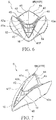
- FIG. 6 is a front view of a front cover.
- FIG. 7 is a three-dimensional view thereof.
- FIG. 8 is a side view thereof.
- FIG. 9 is an enlarged front portion of the scooter-type vehicle when observed from a driver riding the scooter-type vehicle, and is a diagram indicating that the handlebar is rotated to the maximum angle.
- a front cover 9 is disposed in front of the head pipe 21.
- the front cover 9 has a front plane 40 extending backwards and upwards in a side view, and a front cover upper portion 41 formed in a manner protruding upwards relative to the front plane 40 also in a side view.
- a headlamp 15 is disposed in a lower portion of the front cover 9.
- the headlamp 15 is disposed below the front plane 40.
- the headlamp 15 has a headlamp cover 15c, as shown in FIG. 2 and FIG. 4 , the headlamp cover 15c of the headlamp 15 is disposed in the lower portion of the front cover 9, and a part thereof is exposed from an opening 9a of the lower portion of the front cover 9.
- a lamp body not shown is disposed on an inner side of the headlamp 15.
- a relatively large headlamp is employed in order to increase the quantity of light irradiated or emitted from the headlamp 15. As shown in FIG.
- the headlamp 15, for example in a front view, is V-shaped, and an upper edge 15b extends from the center in the vehicle width direction towards an outer side (left and right sides) in the vehicle width direction and above. Also, in a front view, the headlamp 15, for example, is in bilateral symmetry relative to a central line in the vehicle width direction. The length in the vehicle width direction of the headlamp 15 is longer than that of the front cover upper portion 41.
- a vehicle width direction right end of the headlamp 15 is located closer to a vehicle width direction outer side (right side) than a vehicle width direction right end 45 of the front cover upper portion 41, and a vehicle width direction left end of the headlamp 15 is located closer to a vehicle width direction outer side (left side) than a vehicle width direction left end 46 of the front cover upper portion 41.
- the upper end of the headlamp 15 is located further below than a lower end of the front cover upper portion 41, that is, the front end 41 F. Also, as shown in FIG. 4 , in a side view, the headlamp 15 extends backwards and upwards.
- a rear up-down direction length is shorter than the front one of the headlamp 15.
- the front end 15a of the headlamp 15 is located further forward than the axle 6a of the front wheel 6. That is, the front end 15a of the headlamp cover 15c of the headlamp 15 is located further forward than the axle 6a of the front wheel 6.
- the front end 15a of the headlamp 15 is located further rearward than the front end 6F of the front wheel 6, and is higher than a lower end of the head pipe 21 and higher than an upper end of the bottom bracket 11.
- a position lamp 16 smaller than the headlamp 15 and in a triangular shape is disposed in a lower portion of the front plane 40 and above the headlamp 15. As shown in FIG. 2 , the position lamp 16 is disposed in the center in the vehicle width direction. Also, as shown in FIG. 4 , the position lamp 16 is entirely located further forward than the axle 6a of the front wheel 6. Moreover, the configuration, shape, and size of the headlamp are not limited to the above. For example, the front end of the headlamp may also be located further forward than the front wheel of the vehicle wheel. Also, for example, the length of the headlamp in the vehicle width direction may also be shorter than that of the front cover upper portion.
- the front cover 9 has a front plane 40 extending backwards and upwards from the upper edge 15b of the headlamp 15. As shown in FIG. 2 , in a front view, the front plane 40 is disposed between the headlamp 15 and the front cover upper portion 41 and on a vehicle width direction outer side (right and left) of the front cover upper portion 41. Also, the front cover 9 has left and right planes 49 disposed on vehicle width direction outer sides (right and left) of the headlamp 15. In a front view, the front plane 40 and the left and right planes 49, for example, are in bilateral symmetry relative to the central line in the vehicle width direction. As shown in FIG. 3 , in a top view, the front plane 40 extends to be further rearward than the front cover upper portion 41. As shown in FIG.
- a tilt angle of a front surface (surface) of the front plane 40 relative to the horizontal plane is more gentle.
- the configuration, shape, and size of the front plane are not limited to the above.
- the front cover 9 has a front cover upper portion 41, and the front cover upper portion 41 is located at the center in the vehicle width direction of the upper portion of the front cover, and at least one part thereof is located between one end (right end 34) and the other end (left end 35) in the vehicle width direction of the instruction unit 30, and extends backwards and upwards.
- the front cover upper portion 41 formed in a manner protruding upwards relative to the front plane 40 of the front cover 9 as in the present invention sometimes is also referred to as a visor plate.
- the front cover upper portion 41 is a member preventing raindrops from reaching the metering unit 31. As shown in FIG.
- the front cover upper portion 41 is formed, in a side view, in a manner protruding upwards relative to the front plane 40. That is, in this implementation form, the "front cover upper portion” refers to a part (a hatched portion of FIG. 8 ) protruding upwards relative to the front plane 40.
- the front cover upper portion 41 is, in a vehicle width direction, at least partially located between the right end 34 and the left end 35 in the vehicle width direction of the metering unit 30. In other words, at least one part of the front cover upper portion 41 overlaps with the metering unit 30 in a vehicle width direction.
- the length of the front cover upper portion 41 in the vehicle width direction is longer than that of the metering unit 30.
- the right end 45 of the front cover upper portion 41 in the vehicle width direction is located closer to the outer side (right side) in the vehicle width direction than the right end 34 of the metering unit 30 in the vehicle width direction
- the left end 46 of the front cover upper portion 41 in the vehicle width direction is located closer to the outer side (left side) in the vehicle width direction than the left end 35 of the metering unit 30 in the vehicle width direction.
- at least one part of the upper portion of the front cover is located between the right end and the left end in the vehicle width direction of the metering unit.
- the length of the metering unit in the vehicle width direction and the length of the front cover upper portion in the vehicle width direction may also be identical.
- the right end of the front cover upper portion in the vehicle width direction may also be located closer to the outer side (right side) in the vehicle width direction than the right end of the metering unit in the vehicle width direction, while the left end of the front cover upper portion in the vehicle width direction is located closer to the inner side in the vehicle width direction than the left end of the metering unit in the vehicle width direction.
- the left end of the front cover upper portion in the vehicle width direction may also be located closer to the outer side (left side) in the vehicle width direction than the left end of the metering unit in the vehicle width direction, and the right end of the front cover upper portion in the vehicle width direction is located closer to the inner side in the vehicle width direction than the right end of the metering unit in the vehicle width direction.
- the right end of the front cover upper portion in the vehicle width direction may be located closer to the inner side in the vehicle width direction than the right end of the metering unit in the vehicle width direction, and the left end of the front cover upper portion in the vehicle width direction is located closer to the inner side in the vehicle width direction than the left end of the metering unit in the vehicle width direction. Therefore, for example, the length of the front cover upper portion in the vehicle width direction may also be shorter than that of the metering unit.
- the front cover upper portion 41 has: a right surface 42 (first surface), formed in a manner that a right edge 42a (vehicle width direction outer-side end portion) is located further rearward than the center in the vehicle width direction; and a left surface 43 (second surface), formed in a manner that a left edge 43a (vehicle width direction outer-side end portion) opposite a side where the right surface 42 (first surface) is disposed is located further rearward than the center in the vehicle width direction. That is, as shown in FIGs.
- the front cover upper portion 41 is divided into a right surface 42 (first surface) and a left surface 43 (second surface) by using the front edge 41a of the center in the vehicle width direction as a boundary.
- the right surface 42 is formed in a manner that a right edge 42a (vehicle width direction outer-side end portion) is located further rearward than the front edge 41a of the center in the vehicle width direction and tilts rightwards and backwards.
- the left surface 43 (second surface) is formed in a manner that a left edge 43a (vehicle width direction outer-side end portion) is located further rearward than the front edge 41a of the center in the vehicle width direction and tilts leftwards and backwards.
- the rear end 41R of the center in the vehicle width direction of the front cover upper portion 41 (the same as the rear end 9R of the center in the vehicle width direction of the front cover 9) is located further forward than the metering unit 30, and located further below than the upper end 30U of the metering unit 30. Also, as shown in FIG. 2 , the rear end 41R of the center in the vehicle width direction of the front cover upper portion 41 is located further above or higher than the lower end 30L of the metering unit 30.
- the wiring harness portion 18 extending downwards from the bottom 33 of the metering 30, in a front view, is hidden behind the front cover upper portion 41.
- an extension line EL1 of the center in the vehicle width direction of the front cover 9 passes further forward than the metering unit 30.
- the extension line EL1 is a straight line that connects the front end 9F and the rear end 9R of the front edge 41a of the center in the vehicle width direction of the front cover 9. That is, a tilt angle ⁇ 1 from the front end 9F of the front edge 41a of the center in the vehicle width direction of the front cover 9 to the rear end 9R, that is, an angle relative to the horizontal line in a side view, is set in a manner passing through a position further forward than the metering unit 30.
- the metering unit 30 is set in a manner being within a tilt angle ⁇ 1 of an acute angle formed by the extension line EL1 and the horizontal line.
- the muddy water on the front cover 9 that reaches the rear end 9R of the center in the vehicle width direction of the front cover 9 splashes towards the direction of the extension line EL1 of the center in the vehicle width direction of the front cover 9 in a side view. Therefore, if the tilt angle ⁇ 1 is set in a manner becoming an angle passing through a position further forward than the metering unit 30, the muddy water splashes along the extension line EL1, and easily splashes upwards in front of the metering unit 30. Therefore, the muddy water impacting the metering unit 30 is reduced.
- the tilt angle ⁇ 1 for example, is set to be above 40 degrees and below 50 degrees. However, the tilt angle ⁇ 1 is not limited thereto.
- the extension line of the front edge 41a of the front cover upper portion 41 also passes through the position further forward than the metering unit 30.
- the extension line EL2 of the front cover upper portion is a straight line that connects the front end 41F and the rear end 41R of the center in the vehicle width direction of the front cover upper portion 41. That is, a tilt angle ⁇ 2 from the front end 41F of the center in the vehicle width direction of the front cover upper portion 41 to the rear end 41R, that is, an angle ⁇ 2 relative to the horizontal line in a side view, is set in a manner passing through a position further forward than the metering unit 30.
- the metering unit 30 is set in a manner being within a tilt angle ⁇ 2 of an acute angle formed by the extension line EL2 of the front cover upper portion and the horizontal line.
- the vehicle front-back-direction length L1 in the vehicle width direction of the front cover upper portion 41 is longer than the up-down-direction length L2.
- the vehicle front-back-direction length L1 in the vehicle width direction of the front edge 41a of the front cover upper portion 41 is longer than the up-down-direction length L2.
- the tilt angle ⁇ 2 from the front end 41F of the center in the vehicle width direction of the front cover upper portion 41 to the rear end 41R, that is, the angle relative to the horizontal line in a side view, is less than 45 degrees.
- the front end 9F of the center in the vehicle width direction of the front cover 9 is located further forward than the front end 15a of the headlamp 15.
- the front end 9F of the center in the vehicle width direction of the front cover 9 is located further forward than the front end 15a of the headlamp 15, even if the muddy water swept up by the front wheel 6 is on the headlamp 15, it is also difficult for the muddy water to further move from the headlamp 15 to the surface of the front cover 9. Therefore, the quantity of the muddy water splashing backwards from the rear end 41R in the vehicle width direction of the front cover 9 is reduced, which can inhibit the muddy water from splashing to the metering unit 30.
- the front end of the center in the vehicle width direction of the front cover may also be located further rearward than the front end of the headlamp.
- the front end 9F of the center in the vehicle width direction of the front cover 9 is located further forward than the axle 6a of the front wheel 6, and located further rearward than the front end 6F of the front wheel 6.
- the front end 41F of the center in the vehicle width direction of the front cover upper portion 41 is located further forward than the front end 21F of the head pipe 21.
- the front end 41F of the center in the vehicle width direction of the front cover upper portion 41 is located further rearward the front end 9F of the center in the vehicle width direction of the front cover 9.
- the rear edge 44 of the front cover upper portion 41 including the rear end 41R (9R) of the center in the vehicle width direction of the front cover upper portion 41 tilts towards a side and a lower side of the vehicle in a front view in a manner that, in the front view, the outer ends 45 and 46 of the rear edge 44 in the vehicle width direction are located further below than the rear end 41R.
- the rear edge 44 of the front cover upper portion 41 tilts towards the front and the lower side in a side view in a manner that, in the side view, the outer ends 45 and 46 are located further below than the rear end 41R.
- the rear edge 44 passes under the handlebar 7 when the rear edge is in a state where the handlebar 7 is rotated to the maximum angle. That is, in a state where the handlebar 7 is rotated to the maximum angle, a gap exists between the handlebar 7 and the rear edge 44 in a vehicle up-down direction, and the handlebar 7 will not contact the rear edge 44 even in a state where the handlebar 7 is rotated to the maximum angle.
- the lower portion of the front cover upper portion 41 in a side view is located further above or higher than the front plane 40 in the side view.
- a horn hole 19 for the sound of the following horn 12 to pass through is disposed between the lower portion of the front cover upper portion 41 and the front plane 40 in the up-down direction. In the front view, the horn hole 19 is located further below than the lower portion of the front cover upper portion 41.
- the handlebar 7 is now described in detail with reference to FIGs. 2-4 .
- the handle 7 is supported on an upper end portion of the steering shaft 10.
- the handlebar 7 is, in a front view, substantially in a Y shape with a concave portion 7a in the central portion.
- the handlebar 7 has a grip portion 7b for a rider to grip.
- the grip portion 7b is disposed at two ends in the vehicle width direction.
- the rear end 41R of the center in the vehicle width direction of the front cover upper portion 41 is located further below than an upper end 7b1 of the grip portion 7b of the handlebar 7.
- the rear end 41R may be located below, to enable the upper portion of the front cover 9 to be reduced in size in an up-down direction.
- the metering unit 30 is now described in detail with reference to FIGs. 2-5 .
- the metering unit 30 is mounted to the center in the vehicle width direction of the handlebar 7. As shown in FIG. 2 , the metering unit 30 is mounted to the concave portion 7a of the handle 7.
- the lower end 30L of the metering unit 30 is located further below than the grip portion 7b of the handlebar 7.
- the metering unit 30 is located further rearward than the rear end 41R of the center in the vehicle width direction of the front cover upper portion 41.
- the metering unit 30 is substantially rectangular, and is longer in the vehicle width direction length than the front-back direction length. As shown in FIG. 4 , the front-back direction length of the metering unit 30 is shorter than the front-back direction length of the front end 21F of the head pipe 21 to the rear end 21R. Also, a display portion 31 is disposed inside the metering unit 30. For example, a current vehicle speed is displayed in the display portion 31.
- the metering unit 30 has a transparent cover 32.
- the transparent cover 32 is disposed on an upper surface of the metering unit 30.
- the rider reads the display portion 31 via the transparent cover 32.
- the transparent cover 32 is disposed in a manner tilting backwards and downwards in a side view, to make it easy for the rider to identify. That is, the line perpendicular to the transparent cover 32 extends towards the direction of the driver's face.
- the metering unit 30 is also entirely disposed in a manner tilting backwards and downwards in a side view.
- the size or mounting direction of the metering unit 30 is not limited thereto.
- the front end 30F of the metering unit 30 is located further forward than the rear end 21R of the head pipe 21, and the rear end 41R of the center in the vehicle width direction of the front cover upper portion 41 is located further rearward than the front end 21F of the head pipe 21.
- a front-back-direction distance between the front end 30F of the metering unit 30 and the rear end 9R of the center in the vehicle width direction of the front cover upper portion 41 is shorter than the front-back-direction length of the metering unit 30.
- the metering unit 30 is entirely disposed further forward than the shaft axis SL of the steering shaft 10.
- the front end 30F of the metering unit 30 is located further rearward than the front end 21F of the head pipe 21. Also, as shown in FIG. 4 , the front end 30F of the metering unit 30 is located further rearward than a vertical line VL passing through the rear end 6R of the front wheel 6. As shown in FIG. 2 , the bottom 33 of the metering unit 30 is connected with a wiring harness portion 18.
- the wiring harness portion 18 is water-proof, extends downwards from the bottom 33 of the metering unit 30, and is connected to electrical parts (not shown) disposed between the front cover 9 and the leg shield 14.
- the scooter-type vehicle 1 has a horn 12 disposed behind the front cover 9.
- the horn 12 is used for sounding an alarm, and is disposed between the front cover 9 and the leg shield 14. That is, the horn 12 is present further rearward than the horn hole 19.
- the horn 12 overlaps with at least one part of the horn hole 19.
- the horn and the horn hole may not overlap.
- the straddle-type vehicle 1 of this implementation form has: a vehicle body frame 2, which has a head pipe 21; a steering shaft 10, rotatably supported on the head pipe 21; a front wheel 6, supported on the vehicle body frame 2 via the steering shaft 10; a handlebar 7, supported on an upper end portion of the steering shaft 10; a metering unit 30, having a transparent cover 32; a front cover 9, disposed in front of the head pipe 21; and a headlamp 15, disposed in a lower portion of the front cover 9; wherein a front end 15a of the headlamp 15 is located further forward than an axle 6a of the front wheel 6, the metering unit 30 is mounted to the center of a vehicle width direction of the handlebar 7, the front cover 9 has a front cover upper portion 41 located in the center in the vehicle width direction of an upper portion thereof, and, in a vehicle width direction, at least partially located between one end and the other end in the vehicle width direction of the metering unit 30 and extending backwards and upwards, a rear end 41R
- the metering unit 30 is disposed on the handlebar 7, it is unnecessary to set an arrangement space of the metering unit 30 in the front cover upper portion 41.
- the rear end 41R of the center in the vehicle width direction of the front cover upper portion 41 is located further forward than the metering unit 30, and located further below than the upper end 30U of the metering unit 30. Therefore, compared with the manner disposing the rear end 41R of the center in the vehicle width direction of the front cover upper portion 41 further above or higher than the upper end 30U of the metering unit 30 and further rearward than the front end 30F of the metering unit 30, the front cover upper portion 41 is reduced. In this way, the upper portion of the front cover 9 can be reduced in size in a front-back direction and an up-down direction.
- the rear end 41R of the center in the vehicle width direction of the front cover upper portion 41 is located above the lower end 30L of the metering unit 30, and thus the muddy water discharged from the rear end 41R of the center in the vehicle width direction of the front cover upper portion 41 splashes upwards and backwards substantially along the tilt angle of the front cover upper portion 41.
- the inventors noticed that, if the rear end 41R of the center in the vehicle width direction of the front cover upper portion 41 is located further below than the lower end of the metering unit 30, the muddy water easily impacts the metering unit 30. Therefore, at first, the rear end 41R of the center in the vehicle width direction of the front cover upper portion 41 is disposed further above or higher than the lower end 30L of the metering unit 30.
- an extension line EL1 of the center in the vehicle width direction of the front cover 9 passes through a position further forward than the metering unit 30. Even if the rear end 41R of the center in the vehicle width direction of the front cover upper portion 41 is disposed further above or higher than the lower end 30L of the metering unit 30, if the tilt angle of the center in the vehicle width direction of the upper portion of the front cover 9 is smaller, the muddy water also easily impacts the metering unit 30. Herein, the muddy water reaching the rear end 41R of the center in the vehicle width direction of the front cover upper portion 41, in a side view, splashes towards the direction of the extension line EL1 of the center in the vehicle width direction of the front cover 9.
- the tilt angle ⁇ 1 is set in a manner passing through a position further forward than the metering unit 30, the muddy water easily splashes along the extension line EL1, and splashes upwards in front of the metering unit 30. Therefore, the muddy water impacting the metering unit 30 is reduced.
- the tilt angle of the center in the vehicle width direction of the front cover 9 easily becomes gentle.
- the tilt angle of the center in the vehicle width direction of the front cover 9 becomes more gentle. If the tilt angle of the center in the vehicle width direction of the front cover 9 becomes gentle, it is difficult for the muddy water on the front cover 9 to flow towards left and right.
- the upper portion of the front cover 9 may be reduced in size in a front-back direction and an up-down direction, and impact on the riders' comfort may be inhibited.
- a front end 30F of the metering unit 30 is located further forward than a rear end 21R of the head pipe 21, and the rear end 41R of the center in the vehicle width direction of the front cover upper portion 41 is located further rearward than a front end 21F of the head pipe 21.
- a front end 30F of the metering unit 30 is located further forward than a rear end 21R of the head pipe 21, and the rear end 41R of the center in the vehicle width direction of the front cover upper portion 41 is located further rearward than a front end 21F of the head pipe 21. Therefore, a vehicle front-back-direction distance between the rear end 41R of the center in the vehicle width direction of the front cover upper portion 41 and the front end 30F of the metering unit 30 is shortened. That is, the rear end 41R of the center in the vehicle width direction of the front cover upper portion 41 is located near the front end 30F of the metering unit 30.
- the muddy water swept up by the front wheel 6 and flowing to the rear end 41R of the center in the vehicle width direction of the front cover upper portion 41 easily goes beyond the metering unit 30. Therefore, the front cover 9 may not become long or extended, the upper portion of the front cover 9 may be reduced in size in a front-back direction and an up-down direction, and impact on the riders' comfort may be inhibited.
- a vehicle front-back-direction length L1 of the center in the vehicle width direction of the front cover upper portion 41 is longer than an up-down-direction length L2.
- a vehicle front-back-direction length L1 of the center in the vehicle width direction of the front cover upper portion 41 is longer than an up-down-direction length L2.
- a tilt angle ⁇ 2 of an extension line EL2 of the front cover upper portion connecting the front end 41F and the rear end 41R of the center in the vehicle width direction of the front cover upper portion 41 relative to the horizontal line is less than 45 degrees. Therefore, for example, as per the straddle-type vehicle described in Patent Document 1, the vehicle front-back-direction length of the center in the vehicle width direction of the front cover upper portion is the same as or shorter than the up-down-direction length.
- the tilting of the center in the vehicle width direction of the front cover upper portion 41 may become gentle.
- the upper portion of the front cover 9 may be reduced in size in an up-down direction.
- the handlebar 7 has a grip portion 7b for a driver to grip, and the rear end 41R of the center in the vehicle width direction of the front cover upper portion 41 is located further below than an upper end 7b1 of the grip portion 7b.
- the rear end 41R of the center in the vehicle width direction of the front cover upper portion 41 may become lower.
- the upper portion of the front cover 9 may be reduced in size in an up-down direction.
- the straddle-type vehicle 1 of this implementation form has a wiring harness portion connected to the bottom 33 of the metering unit 30, wherein in a front view, the wiring harness portion 18 is hidden behind the front cover upper portion 41.
- the upper portion of the front cover 9 shields the wiring harness portion 18 of the metering unit 30 from the front. Therefore, the appearance can be improved when the vehicle is in a front view, and the muddy water splashing towards the wiring harness portion 18 from the front cover 9 can be prevented from splashing to the wiring harness portion 18.
- the metering unit 30 is disposed further forward than a shaft axis SL of the steering shaft 10.
- the metering unit 30 is disposed further forward than a shaft axis SL of the steering shaft 10, and thus the metering unit 30 may be located near the front cover upper portion 41. Therefore, the muddy water swept up by the front wheel 6 and flowing to the rear end 41R of the center in the vehicle width direction of the front cover upper portion 41 easily goes beyond the metering unit 30. Therefore, the front cover 9 may not be extended, the upper portion of the front cover 9 may be reduced in size in a front-back direction and an up-down direction, and impact on the riders' comfort may be inhibited.
- the front cover upper portion 41 has: a right surface 42 (first surface), formed in a manner that a right edge 42a (vehicle width direction outer-side end portion) is located further rearward than the center in the vehicle width direction; and a left surface 43 (second surface), formed in a manner that a left edge 43a (vehicle width direction outer-side end portion) opposite a side where the right surface 42 is disposed is located further rearward than the center in the vehicle width direction.
- the water on the surface of the front cover 9 due to the air flow generated during driving, advances along the right surface 42 (first surface) or the left surface 43 (second surface) towards a vehicle width direction outer side, and splashes from the upper portion of the front cover 9 towards the outer side in the vehicle width direction, and thus the muddy water does not form easily on the transparent cover 32 of the metering unit 30. Therefore, the front cover 9 may not be extended, the upper portion of the front cover 9 may be reduced in size in a front-back direction and an up-down direction, and impact to the riders' comfort may be inhibited.
- a rear edge 44 of the front cover upper portion 41 including the rear end 41R of the center in the vehicle width direction of the front cover upper portion 41 is, in a front view, formed in a manner that vehicle width direction outer ends 45 and 46 are located further below than the rear end 41R, and in a state where the handlebar 7 is rotated to the maximum angle, the rear edge 44 passes under the handlebar 7.
- the handlebar 7 when the handlebar 7 is operated, the handlebar 7 does not interfere with the front cover upper portion 41, and thus a gap between the upper portion of the front cover 9 and the metering unit 30 may be reduced in a vehicle front-back direction.
- the muddy water swept up by the front wheel 6 and flowing to the rear end 41R of the center in the vehicle width direction of the front cover upper portion 41 easily goes beyond the metering unit 30. Therefore, the front cover 9 may not be extended, the upper portion of the front cover 9 may be reduced in size in a front-back direction and an up-down direction, and impact to the riders' comfort may be inhibited.
- the front cover 9 has a front plane 40 extending backwards and upwards from an upper edge 15b of the headlamp 15, the front cover upper portion 41 is formed in a manner protruding upwards relative to the front plane 40, and the straddle-type vehicle has a horn 12 disposed behind the front cover 9, and a horn hole 19 for the sound of the horn 12 to pass through is disposed between a lower end portion of the front cover upper portion 41 and the front plane 40, wherein in a front view, the horn 12 overlaps with the horn hole 19.
- a horn hole 19 for the sound of the horn 12 to pass is disposed between a lower end portion of the front cover upper portion 41 and the front plane 40, and thus there is an order difference portion formed by the horn hole 19 between the lower end portion of the front cover upper portion 41 and the front plane 40. Therefore, it is difficult for the muddy water swept up by the front wheel 6 and on the front plane 40 of the front cover 9 to reach the surface of the front cover upper portion 41. Therefore, it is difficult for the muddy water to form on the transparent cover 32 of the metering unit 30. In this way, impact on the riders' comfort may be inhibited.
- the upper portion of the front cover is, in a side view, formed in a manner protruding upwards relative to the front plane 40, but the upper portion of the front cover may not be, in a side view, formed in a manner protruding upwards relative to other portions of the front cover.
- the front cover may include a cover surface, and the center of the upper portion thereof is a front cover upper portion.
- the front end 30F of the metering unit 30 is located further forward than the rear end 21R of the head pipe 21, the rear end 9R of the center in the vehicle width direction of the upper portion of the front cover 9 is located further rearward than the front end of the head pipe 21, but the front end of the metering unit may also be located further rearward the rear end of the head pipe, and the rear end of the center in the vehicle width direction of the front cover upper portion may also be located further forward than the front end of the head pipe.
- the wiring harness portion 18 connected to the bottom 33 of the metering unit 30 is hidden behind the front cover upper portion 41 is described, but the wiring harness portion may not be hidden behind the front cover upper portion.
- the metering unit 30 is disposed further forward than the shaft axis SL of the steering shaft 10 as shown in FIG. 4 is described, but the metering unit may also be partially or wholly disposed further rearward than the shaft axis of the steering shaft.
- the front cover upper portion 41 has: a right surface 42 (first surface), formed in a manner that a right edge 42a (vehicle width direction outer-side end portion) is located further rearward than the center in the vehicle width direction; and a left surface 43 (second surface), formed in a manner that a left edge 43a (vehicle width direction outer-side end portion) opposite a side where the right surface 42 is disposed is located further rearward than the center in the vehicle width direction.
- the front cover upper portion may be formed not in a manner that the outer-side end portion in the vehicle width direction is located further rearward than the center in the vehicle width direction.
- the front cover upper portion may be formed in one plane.
- the situation where the rear edge 44 of the front cover upper portion 41 is formed in a manner that vehicle width direction outer sides 45 and 46 are located further below than the rear end 41R of the center in the vehicle width direction is described, but, for example, the rear edge of the front cover upper portion may also extend horizontally relative to the ground.
- the following situation is described, that is, in a side view, the lower portion of the front cover upper portion 41 is located further above or higher than the front plane 40, and a horn hole 19 for the sound of the horn to pass through is disposed between the lower portion of the front cover upper portion 41 and the front plane 40; however, the horn hole for the sound of the horn to pass may not be disposed between the lower portion of the front cover upper portion and the front plane, and the lower portion of the front cover upper portion may not be located further above or higher than the front plane. That is, the lower portion of the front cover upper portion and the front plane may also be connected without order difference.
- the vehicle front-back-direction length L1 of the center in the vehicle width direction of the front cover upper portion 41 is longer than the up-down-direction length L2.
- a tilt angle ⁇ 2 formed by a line connecting the front end 41F and the rear end 41R of the center in the vehicle width direction of the front cover upper portion 41 and the horizontal line is less than 45 degrees.
- the vehicle front-back-direction length of the center in the vehicle width direction of the front cover upper portion is the same as or shorter than the up-down-direction length.
- the tilt angle formed by the line connecting the front end and the rear end of the center in the vehicle width direction of the front cover upper portion and the horizontal line may also be more than 45 degrees.
- the rear end 41R of the center in the vehicle width direction of the front cover upper portion 41 is located further below than the upper end 7b1 of the grip portion 7b of the handlebar 7, but may also be located in the same position or a higher position in the up-down direction.
- the straddle-type vehicle of the present invention may also have more than three vehicle wheels but not limited to two.
- it may also have two front wheels and one rear wheel.
- the straddle-type vehicle is imited to the scooter-type vehicle.
Landscapes
- Engineering & Computer Science (AREA)
- Mechanical Engineering (AREA)
- Chemical & Material Sciences (AREA)
- Combustion & Propulsion (AREA)
- Transportation (AREA)
- Lighting Device Outwards From Vehicle And Optical Signal (AREA)
- Automatic Cycles, And Cycles In General (AREA)
Claims (9)
- Ein Rollertyp-Fahrzeug, das einen Fahrzeugkarosserierahmen (2) mit einem Kopfrohr (21); eine Lenkwelle (10), die drehbar an dem Kopfrohr (21) getragen wird; ein Vorderrad (6), das über die Lenkwelle (10) an dem Fahrzeugkarosserierahmen (2) getragen wird; einen Lenker (7), der an einem oberen Endabschnitt der Lenkwelle (10) getragen wird; eine Messeinheit (30) mit einer transparenten Abdeckung (32); eine Frontabdeckung (9), die vor dem Kopfrohr (21) angeordnet ist; und einen Frontscheinwerfer (15) aufweist, der in einem unteren Abschnitt der Frontabdeckung (9) angeordnet ist; wobei ein Vorderende (15a) des Frontscheinwerfers (15) weiter vorne angeordnet ist als eine Achse (6a) des Vorderrads (6), wobei die Messeinheit (30) in der Mitte, in einer Fahrzeugbreitenrichtung, des Lenkers (7) befestigt ist, wobei die Messeinheit (30) an einem konkaven Abschnitt (7a) des Lenkers (7) befestigt ist, wobei sich ein unteres Ende (30L) der Messeinheit (30) weiter unten befindet als ein Griffabschnitt (7b) des Lenkers (7), wobei die Frontabdeckung (9) einen oberen Abschnitt (41) der Frontabdeckung aufweist, der sich in der Mitte, in der Fahrzeugbreitenrichtung, eines oberen Abschnitts desselben befindet sowie, in einer Fahrzeugbreitenrichtung, zumindest teilweise zwischen einem Ende und dem anderen Ende, in der Fahrzeugbreitenrichtung, der Messeinheit (30) befindet und sich nach hinten und nach oben erstreckt, wobei sich ein Rückende (41R) der Mitte, in der Fahrzeugbreitenrichtung, des oberen Abschnitts (41) der Frontabdeckung weiter vorne befindet als die Messeinheit (30) und weiter unten befindet als ein oberes Ende (30U) der Messeinheit (30), dadurch gekennzeichnet, dass sich das Rückende (41R) der Mitte, in der Fahrzeugbreitenrichtung, des oberen Abschnitts (41) der Frontabdeckung weiter oben befindet als ein unteres Ende (30L) der Messeinheit (30) und in einer Seitenansicht eine Verlängerungslinie (EL1) der Mitte, in der Fahrzeugbreitenrichtung, der Frontabdeckung (9) durch eine Position verläuft, die sich weiter vorne befindet als die Messeinheit (30), wobei die Verlängerungslinie (EL1) eine gerade Linie ist, die ein Vorderende (9F) und ein Rückende (9R) eines vorderen Rands (41a) der Mitte, in der Fahrzeugbreitenrichtung, der Frontabdeckung (9) verbindet, wobei ein Neigungswinkel Θ1 der Verlängerungslinie (EL1) relativ zu der Horizontallinie in einer Seitenansicht in einer Weise eingestellt ist, dass sie durch eine Position verläuft, die sich weiter vorne befindet als die Messeinheit (30).
- Das Rollertyp-Fahrzeug gemäß Anspruch 1, bei dem sich ein Vorderende der Messeinheit (30) weiter vorne befindet als ein Rückende (21R) des Kopfrohrs (21) und sich das Rückende (41R) der Mitte, in der Fahrzeugbreitenrichtung, des oberen Abschnitts der Frontabdeckung weiter hinten befindet als ein Vorderende des Kopfrohrs (21).
- Das Rollertyp-Fahrzeug gemäß Anspruch 1, bei dem
eine Fahrzeuglänge in Vorne-Hinten-Richtung der Mitte, in der Fahrzeugbreitenrichtung, des oberen Abschnitts der Frontabdeckung länger ist als eine Länge in Oben-Unten-Richtung. - Das Rollertyp-Fahrzeug gemäß Anspruch 1, bei dem der Lenker (7) einen Griffabschnitt (7b) zum Greifen durch einen Fahrer aufweist und
sich das Rückende (41R) der Mitte, in der Fahrzeugbreitenrichtung, der oberen Abschnitte der Frontabdeckung weiter unten befindet als ein oberes Ende (7b1) des Griffabschnitts (7b). - Das Rollertyp-Fahrzeug gemäß Anspruch 1, das einen Kabelbaumabschnitt (18) aufweist, der mit der Unterseite der Messeinheit (30) verbunden ist, wobei
in einer Vorderansicht der Kabelbaumabschnitt (18) hinter dem oberen Abschnitt der Frontabdeckung versteckt ist. - Das Rollertyp-Fahrzeug gemäß Anspruch 1, bei dem die Messeinheit (30) weiter vorne angeordnet ist als eine Wellenachse (SL) der Lenkwelle (10).
- Das Rollertyp-Fahrzeug gemäß Anspruch 1, bei dem der obere Abschnitt der Frontabdeckung folgende Merkmale aufweist:eine erste Oberfläche (42), die in einer Weise gebildet ist, dass sich ein Außenseitenendabschnitt einer Fahrzeugbreitenrichtung weiter hinten befindet als die Mitte, in der Fahrzeugbreitenrichtung; undeine zweite Oberfläche (43), die in einer Weise gebildet ist, dass sich ein Außenseitenendabschnitt der Fahrzeugbreitenrichtung gegenüber von einer Seite, an der die erste Oberfläche (42) angeordnet ist, weiter hinten befindet als die Mitte, in der Fahrzeugbreitenrichtung.
- Das Rollertyp-Fahrzeug gemäß Anspruch 1, bei dem
ein hinterer Rand (44) des oberen Abschnitts der Frontabdeckung mit dem Rückende (41R) der Mitte, in der Fahrzeugbreitenrichtung, des oberen Abschnitts der Frontabdeckung in einer Vorderansicht in einer Weise gebildet ist, dass sich ein Außenende der Fahrzeugbreitenrichtung weiter unten befindet als das Rückende (41R) der Mitte, in der Fahrzeugbreitenrichtung, des oberen Abschnitts der Frontabdeckung, und
in einem Zustand, in dem der Griff (7) in den maximalen Winkel gedreht ist, der hintere Rand (44) unter dem Griff (7) verläuft, - Das Rollertyp-Fahrzeug gemäß Anspruch 1, bei dem die Frontabdeckung (9) eine Vorderebene (40) aufweist, die sich von einem oberen Rand (15b) des Frontscheinwerfers (15) nach hinten und nach oben erstreckt,
der obere Abschnitt der Frontabdeckung in einer Weise gebildet ist, dass er relativ zu der Vorderebene (40) nach oben vorsteht, und
das Rollertyp-Fahrzeug eine Hupe (12) aufweist, die hinter der Frontabdeckung (9) angeordnet ist, und
ein Hupenloch (19), durch das der Schall der Hupe (12) laufen kann, zwischen einem unteren Endabschnitt des oberen Abschnitts der Frontabdeckung und der Vorderebene (40) angeordnet ist,
wobei die Hupe (12) in einer Vorderansicht das Hupenloch (19) überlappt.
Applications Claiming Priority (1)
| Application Number | Priority Date | Filing Date | Title |
|---|---|---|---|
| CN201610375276.7A CN107444536B (zh) | 2016-05-31 | 2016-05-31 | 跨坐型车辆 |
Publications (2)
| Publication Number | Publication Date |
|---|---|
| EP3251925A1 EP3251925A1 (de) | 2017-12-06 |
| EP3251925B1 true EP3251925B1 (de) | 2021-01-06 |
Family
ID=58709308
Family Applications (1)
| Application Number | Title | Priority Date | Filing Date |
|---|---|---|---|
| EP17170873.8A Active EP3251925B1 (de) | 2016-05-31 | 2017-05-12 | Grätschsitzfahrzeug |
Country Status (2)
| Country | Link |
|---|---|
| EP (1) | EP3251925B1 (de) |
| CN (1) | CN107444536B (de) |
Cited By (1)
| Publication number | Priority date | Publication date | Assignee | Title |
|---|---|---|---|---|
| WO2024206429A3 (en) * | 2023-03-30 | 2025-04-17 | Indian Motorcycle International, LLC | Vehicle horn |
Families Citing this family (4)
| Publication number | Priority date | Publication date | Assignee | Title |
|---|---|---|---|---|
| JP6759268B2 (ja) * | 2018-04-02 | 2020-09-23 | 本田技研工業株式会社 | 鞍乗り型車両のメーター周辺構造 |
| JP6982173B2 (ja) * | 2018-05-23 | 2021-12-17 | 本田技研工業株式会社 | 鞍乗型車両 |
| CN111038633B (zh) * | 2018-10-12 | 2021-04-06 | 雅马哈发动机株式会社 | 跨坐型车辆 |
| WO2022163249A1 (ja) * | 2021-01-28 | 2022-08-04 | 本田技研工業株式会社 | 鞍乗り型車両 |
Family Cites Families (18)
| Publication number | Priority date | Publication date | Assignee | Title |
|---|---|---|---|---|
| JP3679164B2 (ja) * | 1995-09-27 | 2005-08-03 | ヤマハ発動機株式会社 | 自動二輪車 |
| JPH11310171A (ja) * | 1998-04-27 | 1999-11-09 | Yamaha Motor Co Ltd | スクータ型車両のスタンディングハンドル配設部構造 |
| JP2007283927A (ja) * | 2006-04-18 | 2007-11-01 | Yamaha Motor Co Ltd | 自動二輪車 |
| JP5013883B2 (ja) * | 2006-10-18 | 2012-08-29 | ヤマハ発動機株式会社 | 自動二輪車 |
| US8235566B2 (en) * | 2007-09-18 | 2012-08-07 | Yamaha Hatsudoki Kabushiki Kaisha | Straddle-type vehicle |
| JP5033751B2 (ja) * | 2008-09-30 | 2012-09-26 | 本田技研工業株式会社 | 車両の前部構造 |
| JP5670779B2 (ja) * | 2011-02-17 | 2015-02-18 | ヤマハ発動機株式会社 | 自動二輪車 |
| TWI549849B (zh) | 2013-01-30 | 2016-09-21 | Yamaha Motor Co Ltd | Straddle type vehicle |
| JP2015120497A (ja) * | 2013-11-20 | 2015-07-02 | ヤマハ発動機株式会社 | 鞍乗型車両 |
| CN104554525B (zh) * | 2013-10-22 | 2019-12-10 | 雅马哈发动机株式会社 | 跨坐型车辆 |
| CN104554530B (zh) * | 2013-10-22 | 2017-07-28 | 雅马哈发动机株式会社 | 跨坐型车辆 |
| CN104554557B (zh) * | 2013-10-22 | 2017-11-17 | 雅马哈发动机株式会社 | 跨坐型车辆 |
| CN105270516A (zh) * | 2014-06-03 | 2016-01-27 | 光阳工业股份有限公司 | 摩托车电子产品固定结构 |
| JP2016078497A (ja) * | 2014-10-10 | 2016-05-16 | ヤマハ発動機株式会社 | 鞍乗型車両 |
| TWI570007B (zh) | 2014-10-24 | 2017-02-11 | Yamaha Motor Co Ltd | Straddle type vehicle |
| CN105584571B (zh) * | 2014-10-24 | 2018-10-19 | 雅马哈发动机株式会社 | 跨坐型车辆 |
| JP2016088232A (ja) * | 2014-10-31 | 2016-05-23 | ヤマハ発動機株式会社 | 車両 |
| CN105059434B (zh) * | 2015-07-14 | 2018-02-16 | 力帆实业(集团)股份有限公司 | 摩托车前照灯、后视镜及仪表盘组合式安装支架 |
-
2016
- 2016-05-31 CN CN201610375276.7A patent/CN107444536B/zh active Active
-
2017
- 2017-05-12 EP EP17170873.8A patent/EP3251925B1/de active Active
Non-Patent Citations (1)
| Title |
|---|
| None * |
Cited By (1)
| Publication number | Priority date | Publication date | Assignee | Title |
|---|---|---|---|---|
| WO2024206429A3 (en) * | 2023-03-30 | 2025-04-17 | Indian Motorcycle International, LLC | Vehicle horn |
Also Published As
| Publication number | Publication date |
|---|---|
| CN107444536B (zh) | 2020-11-10 |
| EP3251925A1 (de) | 2017-12-06 |
| CN107444536A (zh) | 2017-12-08 |
Similar Documents
| Publication | Publication Date | Title |
|---|---|---|
| EP3251925B1 (de) | Grätschsitzfahrzeug | |
| EP2463184B1 (de) | Motorrad | |
| JP3154590U (ja) | 自動二輪車 | |
| JP2008024289A (ja) | 自動二輪車 | |
| US7325853B2 (en) | Arrangement structure of upper cowl, screen, and meter for motorcycles | |
| EP2644483B1 (de) | Sattelfahrzeug | |
| CN102398650B (zh) | 鞍乘型车辆的腿部遮护板结构 | |
| BR102016003183A2 (pt) | estrutura frontal de veículo do tipo para montar | |
| TWI865855B (zh) | 跨坐型車輛 | |
| JP7819484B2 (ja) | 鞍乗型車両 | |
| EP2876027B1 (de) | Sattelfahrzeug | |
| US9581073B2 (en) | Radiator structure for two-wheeled vehicle | |
| CN102910237B (zh) | 摩托车 | |
| EP2221220B1 (de) | Motorrad | |
| JP6498231B2 (ja) | フォークガード構造 | |
| JP6356627B2 (ja) | ウィンカーを備える鞍乗り型車両 | |
| CN103010349A (zh) | 车辆的前部结构 | |
| JP5088087B2 (ja) | スクータ型車両の後部車体構造 | |
| JP6130150B2 (ja) | フォークガード構造 | |
| JP7450773B2 (ja) | 鞍乗り型車両 | |
| JP5953082B2 (ja) | 鞍乗型車両のリヤフェンダの構造 | |
| TWI615309B (zh) | 跨坐型車輛 | |
| JP7211053B2 (ja) | 鞍乗型車両のフロントフェンダ構造 | |
| JP2019181970A (ja) | 鞍乗り型車両 | |
| CN104144846B (zh) | 鞍乘型车辆的前部结构 |
Legal Events
| Date | Code | Title | Description |
|---|---|---|---|
| PUAI | Public reference made under article 153(3) epc to a published international application that has entered the european phase |
Free format text: ORIGINAL CODE: 0009012 |
|
| STAA | Information on the status of an ep patent application or granted ep patent |
Free format text: STATUS: THE APPLICATION HAS BEEN PUBLISHED |
|
| AK | Designated contracting states |
Kind code of ref document: A1 Designated state(s): AL AT BE BG CH CY CZ DE DK EE ES FI FR GB GR HR HU IE IS IT LI LT LU LV MC MK MT NL NO PL PT RO RS SE SI SK SM TR |
|
| AX | Request for extension of the european patent |
Extension state: BA ME |
|
| STAA | Information on the status of an ep patent application or granted ep patent |
Free format text: STATUS: REQUEST FOR EXAMINATION WAS MADE |
|
| 17P | Request for examination filed |
Effective date: 20180511 |
|
| RBV | Designated contracting states (corrected) |
Designated state(s): AL AT BE BG CH CY CZ DE DK EE ES FI FR GB GR HR HU IE IS IT LI LT LU LV MC MK MT NL NO PL PT RO RS SE SI SK SM TR |
|
| STAA | Information on the status of an ep patent application or granted ep patent |
Free format text: STATUS: EXAMINATION IS IN PROGRESS |
|
| 17Q | First examination report despatched |
Effective date: 20180827 |
|
| GRAP | Despatch of communication of intention to grant a patent |
Free format text: ORIGINAL CODE: EPIDOSNIGR1 |
|
| STAA | Information on the status of an ep patent application or granted ep patent |
Free format text: STATUS: GRANT OF PATENT IS INTENDED |
|
| INTG | Intention to grant announced |
Effective date: 20200623 |
|
| GRAS | Grant fee paid |
Free format text: ORIGINAL CODE: EPIDOSNIGR3 |
|
| GRAJ | Information related to disapproval of communication of intention to grant by the applicant or resumption of examination proceedings by the epo deleted |
Free format text: ORIGINAL CODE: EPIDOSDIGR1 |
|
| GRAL | Information related to payment of fee for publishing/printing deleted |
Free format text: ORIGINAL CODE: EPIDOSDIGR3 |
|
| STAA | Information on the status of an ep patent application or granted ep patent |
Free format text: STATUS: EXAMINATION IS IN PROGRESS |
|
| GRAR | Information related to intention to grant a patent recorded |
Free format text: ORIGINAL CODE: EPIDOSNIGR71 |
|
| STAA | Information on the status of an ep patent application or granted ep patent |
Free format text: STATUS: GRANT OF PATENT IS INTENDED |
|
| GRAA | (expected) grant |
Free format text: ORIGINAL CODE: 0009210 |
|
| STAA | Information on the status of an ep patent application or granted ep patent |
Free format text: STATUS: THE PATENT HAS BEEN GRANTED |
|
| INTC | Intention to grant announced (deleted) | ||
| AK | Designated contracting states |
Kind code of ref document: B1 Designated state(s): AL AT BE BG CH CY CZ DE DK EE ES FI FR GB GR HR HU IE IS IT LI LT LU LV MC MK MT NL NO PL PT RO RS SE SI SK SM TR |
|
| INTG | Intention to grant announced |
Effective date: 20201127 |
|
| REG | Reference to a national code |
Ref country code: GB Ref legal event code: FG4D |
|
| REG | Reference to a national code |
Ref country code: AT Ref legal event code: REF Ref document number: 1352061 Country of ref document: AT Kind code of ref document: T Effective date: 20210115 Ref country code: CH Ref legal event code: EP |
|
| REG | Reference to a national code |
Ref country code: DE Ref legal event code: R096 Ref document number: 602017030778 Country of ref document: DE |
|
| REG | Reference to a national code |
Ref country code: IE Ref legal event code: FG4D |
|
| REG | Reference to a national code |
Ref country code: NL Ref legal event code: MP Effective date: 20210106 |
|
| REG | Reference to a national code |
Ref country code: AT Ref legal event code: MK05 Ref document number: 1352061 Country of ref document: AT Kind code of ref document: T Effective date: 20210106 |
|
| REG | Reference to a national code |
Ref country code: LT Ref legal event code: MG9D |
|
| PG25 | Lapsed in a contracting state [announced via postgrant information from national office to epo] |
Ref country code: LT Free format text: LAPSE BECAUSE OF FAILURE TO SUBMIT A TRANSLATION OF THE DESCRIPTION OR TO PAY THE FEE WITHIN THE PRESCRIBED TIME-LIMIT Effective date: 20210106 Ref country code: BG Free format text: LAPSE BECAUSE OF FAILURE TO SUBMIT A TRANSLATION OF THE DESCRIPTION OR TO PAY THE FEE WITHIN THE PRESCRIBED TIME-LIMIT Effective date: 20210406 Ref country code: HR Free format text: LAPSE BECAUSE OF FAILURE TO SUBMIT A TRANSLATION OF THE DESCRIPTION OR TO PAY THE FEE WITHIN THE PRESCRIBED TIME-LIMIT Effective date: 20210106 Ref country code: GR Free format text: LAPSE BECAUSE OF FAILURE TO SUBMIT A TRANSLATION OF THE DESCRIPTION OR TO PAY THE FEE WITHIN THE PRESCRIBED TIME-LIMIT Effective date: 20210407 Ref country code: FI Free format text: LAPSE BECAUSE OF FAILURE TO SUBMIT A TRANSLATION OF THE DESCRIPTION OR TO PAY THE FEE WITHIN THE PRESCRIBED TIME-LIMIT Effective date: 20210106 Ref country code: PT Free format text: LAPSE BECAUSE OF FAILURE TO SUBMIT A TRANSLATION OF THE DESCRIPTION OR TO PAY THE FEE WITHIN THE PRESCRIBED TIME-LIMIT Effective date: 20210506 Ref country code: NO Free format text: LAPSE BECAUSE OF FAILURE TO SUBMIT A TRANSLATION OF THE DESCRIPTION OR TO PAY THE FEE WITHIN THE PRESCRIBED TIME-LIMIT Effective date: 20210406 |
|
| PG25 | Lapsed in a contracting state [announced via postgrant information from national office to epo] |
Ref country code: SE Free format text: LAPSE BECAUSE OF FAILURE TO SUBMIT A TRANSLATION OF THE DESCRIPTION OR TO PAY THE FEE WITHIN THE PRESCRIBED TIME-LIMIT Effective date: 20210106 Ref country code: AT Free format text: LAPSE BECAUSE OF FAILURE TO SUBMIT A TRANSLATION OF THE DESCRIPTION OR TO PAY THE FEE WITHIN THE PRESCRIBED TIME-LIMIT Effective date: 20210106 Ref country code: RS Free format text: LAPSE BECAUSE OF FAILURE TO SUBMIT A TRANSLATION OF THE DESCRIPTION OR TO PAY THE FEE WITHIN THE PRESCRIBED TIME-LIMIT Effective date: 20210106 Ref country code: PL Free format text: LAPSE BECAUSE OF FAILURE TO SUBMIT A TRANSLATION OF THE DESCRIPTION OR TO PAY THE FEE WITHIN THE PRESCRIBED TIME-LIMIT Effective date: 20210106 Ref country code: LV Free format text: LAPSE BECAUSE OF FAILURE TO SUBMIT A TRANSLATION OF THE DESCRIPTION OR TO PAY THE FEE WITHIN THE PRESCRIBED TIME-LIMIT Effective date: 20210106 |
|
| PG25 | Lapsed in a contracting state [announced via postgrant information from national office to epo] |
Ref country code: IS Free format text: LAPSE BECAUSE OF FAILURE TO SUBMIT A TRANSLATION OF THE DESCRIPTION OR TO PAY THE FEE WITHIN THE PRESCRIBED TIME-LIMIT Effective date: 20210506 |
|
| REG | Reference to a national code |
Ref country code: DE Ref legal event code: R097 Ref document number: 602017030778 Country of ref document: DE |
|
| PG25 | Lapsed in a contracting state [announced via postgrant information from national office to epo] |
Ref country code: CZ Free format text: LAPSE BECAUSE OF FAILURE TO SUBMIT A TRANSLATION OF THE DESCRIPTION OR TO PAY THE FEE WITHIN THE PRESCRIBED TIME-LIMIT Effective date: 20210106 Ref country code: EE Free format text: LAPSE BECAUSE OF FAILURE TO SUBMIT A TRANSLATION OF THE DESCRIPTION OR TO PAY THE FEE WITHIN THE PRESCRIBED TIME-LIMIT Effective date: 20210106 Ref country code: SM Free format text: LAPSE BECAUSE OF FAILURE TO SUBMIT A TRANSLATION OF THE DESCRIPTION OR TO PAY THE FEE WITHIN THE PRESCRIBED TIME-LIMIT Effective date: 20210106 |
|
| PLBE | No opposition filed within time limit |
Free format text: ORIGINAL CODE: 0009261 |
|
| STAA | Information on the status of an ep patent application or granted ep patent |
Free format text: STATUS: NO OPPOSITION FILED WITHIN TIME LIMIT |
|
| PG25 | Lapsed in a contracting state [announced via postgrant information from national office to epo] |
Ref country code: DK Free format text: LAPSE BECAUSE OF FAILURE TO SUBMIT A TRANSLATION OF THE DESCRIPTION OR TO PAY THE FEE WITHIN THE PRESCRIBED TIME-LIMIT Effective date: 20210106 Ref country code: RO Free format text: LAPSE BECAUSE OF FAILURE TO SUBMIT A TRANSLATION OF THE DESCRIPTION OR TO PAY THE FEE WITHIN THE PRESCRIBED TIME-LIMIT Effective date: 20210106 Ref country code: SK Free format text: LAPSE BECAUSE OF FAILURE TO SUBMIT A TRANSLATION OF THE DESCRIPTION OR TO PAY THE FEE WITHIN THE PRESCRIBED TIME-LIMIT Effective date: 20210106 |
|
| 26N | No opposition filed |
Effective date: 20211007 |
|
| REG | Reference to a national code |
Ref country code: CH Ref legal event code: PL |
|
| GBPC | Gb: european patent ceased through non-payment of renewal fee |
Effective date: 20210512 |
|
| PG25 | Lapsed in a contracting state [announced via postgrant information from national office to epo] |
Ref country code: AL Free format text: LAPSE BECAUSE OF FAILURE TO SUBMIT A TRANSLATION OF THE DESCRIPTION OR TO PAY THE FEE WITHIN THE PRESCRIBED TIME-LIMIT Effective date: 20210106 Ref country code: CH Free format text: LAPSE BECAUSE OF NON-PAYMENT OF DUE FEES Effective date: 20210531 Ref country code: LI Free format text: LAPSE BECAUSE OF NON-PAYMENT OF DUE FEES Effective date: 20210531 Ref country code: LU Free format text: LAPSE BECAUSE OF NON-PAYMENT OF DUE FEES Effective date: 20210512 Ref country code: MC Free format text: LAPSE BECAUSE OF FAILURE TO SUBMIT A TRANSLATION OF THE DESCRIPTION OR TO PAY THE FEE WITHIN THE PRESCRIBED TIME-LIMIT Effective date: 20210106 Ref country code: ES Free format text: LAPSE BECAUSE OF FAILURE TO SUBMIT A TRANSLATION OF THE DESCRIPTION OR TO PAY THE FEE WITHIN THE PRESCRIBED TIME-LIMIT Effective date: 20210106 |
|
| REG | Reference to a national code |
Ref country code: BE Ref legal event code: MM Effective date: 20210531 |
|
| PG25 | Lapsed in a contracting state [announced via postgrant information from national office to epo] |
Ref country code: SI Free format text: LAPSE BECAUSE OF FAILURE TO SUBMIT A TRANSLATION OF THE DESCRIPTION OR TO PAY THE FEE WITHIN THE PRESCRIBED TIME-LIMIT Effective date: 20210106 |
|
| PG25 | Lapsed in a contracting state [announced via postgrant information from national office to epo] |
Ref country code: IE Free format text: LAPSE BECAUSE OF NON-PAYMENT OF DUE FEES Effective date: 20210512 Ref country code: GB Free format text: LAPSE BECAUSE OF NON-PAYMENT OF DUE FEES Effective date: 20210512 |
|
| PG25 | Lapsed in a contracting state [announced via postgrant information from national office to epo] |
Ref country code: IS Free format text: LAPSE BECAUSE OF FAILURE TO SUBMIT A TRANSLATION OF THE DESCRIPTION OR TO PAY THE FEE WITHIN THE PRESCRIBED TIME-LIMIT Effective date: 20210506 |
|
| PG25 | Lapsed in a contracting state [announced via postgrant information from national office to epo] |
Ref country code: BE Free format text: LAPSE BECAUSE OF NON-PAYMENT OF DUE FEES Effective date: 20210531 |
|
| PG25 | Lapsed in a contracting state [announced via postgrant information from national office to epo] |
Ref country code: HU Free format text: LAPSE BECAUSE OF FAILURE TO SUBMIT A TRANSLATION OF THE DESCRIPTION OR TO PAY THE FEE WITHIN THE PRESCRIBED TIME-LIMIT; INVALID AB INITIO Effective date: 20170512 |
|
| PG25 | Lapsed in a contracting state [announced via postgrant information from national office to epo] |
Ref country code: NL Free format text: LAPSE BECAUSE OF NON-PAYMENT OF DUE FEES Effective date: 20210206 Ref country code: CY Free format text: LAPSE BECAUSE OF FAILURE TO SUBMIT A TRANSLATION OF THE DESCRIPTION OR TO PAY THE FEE WITHIN THE PRESCRIBED TIME-LIMIT Effective date: 20210106 |
|
| P01 | Opt-out of the competence of the unified patent court (upc) registered |
Effective date: 20230527 |
|
| PG25 | Lapsed in a contracting state [announced via postgrant information from national office to epo] |
Ref country code: MK Free format text: LAPSE BECAUSE OF FAILURE TO SUBMIT A TRANSLATION OF THE DESCRIPTION OR TO PAY THE FEE WITHIN THE PRESCRIBED TIME-LIMIT Effective date: 20210106 |
|
| PG25 | Lapsed in a contracting state [announced via postgrant information from national office to epo] |
Ref country code: MT Free format text: LAPSE BECAUSE OF FAILURE TO SUBMIT A TRANSLATION OF THE DESCRIPTION OR TO PAY THE FEE WITHIN THE PRESCRIBED TIME-LIMIT Effective date: 20210106 |
|
| PGFP | Annual fee paid to national office [announced via postgrant information from national office to epo] |
Ref country code: DE Payment date: 20250521 Year of fee payment: 9 |
|
| PGFP | Annual fee paid to national office [announced via postgrant information from national office to epo] |
Ref country code: IT Payment date: 20250527 Year of fee payment: 9 |
|
| PGFP | Annual fee paid to national office [announced via postgrant information from national office to epo] |
Ref country code: FR Payment date: 20250528 Year of fee payment: 9 |
|
| PG25 | Lapsed in a contracting state [announced via postgrant information from national office to epo] |
Ref country code: TR Free format text: LAPSE BECAUSE OF FAILURE TO SUBMIT A TRANSLATION OF THE DESCRIPTION OR TO PAY THE FEE WITHIN THE PRESCRIBED TIME-LIMIT Effective date: 20210106 |