EP3247907B1 - Vakuumabgassystem und in diesem vakuumabgassystem verwendetes kanalschaltventil - Google Patents
Vakuumabgassystem und in diesem vakuumabgassystem verwendetes kanalschaltventil Download PDFInfo
- Publication number
- EP3247907B1 EP3247907B1 EP16700506.5A EP16700506A EP3247907B1 EP 3247907 B1 EP3247907 B1 EP 3247907B1 EP 16700506 A EP16700506 A EP 16700506A EP 3247907 B1 EP3247907 B1 EP 3247907B1
- Authority
- EP
- European Patent Office
- Prior art keywords
- pump
- channel
- gas
- exhaust system
- channels
- Prior art date
- Legal status (The legal status is an assumption and is not a legal conclusion. Google has not performed a legal analysis and makes no representation as to the accuracy of the status listed.)
- Active
Links
- 238000005086 pumping Methods 0.000 claims description 12
- 239000007789 gas Substances 0.000 description 100
- 238000000034 method Methods 0.000 description 23
- 239000007795 chemical reaction product Substances 0.000 description 8
- 238000006243 chemical reaction Methods 0.000 description 7
- 238000004140 cleaning Methods 0.000 description 7
- 238000011144 upstream manufacturing Methods 0.000 description 4
- 238000003745 diagnosis Methods 0.000 description 3
- 238000004519 manufacturing process Methods 0.000 description 3
- 239000004065 semiconductor Substances 0.000 description 3
- 230000002159 abnormal effect Effects 0.000 description 1
- 238000009825 accumulation Methods 0.000 description 1
- 238000010586 diagram Methods 0.000 description 1
- 230000000694 effects Effects 0.000 description 1
- 239000010687 lubricating oil Substances 0.000 description 1
- 238000012552 review Methods 0.000 description 1
Images
Classifications
-
- C—CHEMISTRY; METALLURGY
- C23—COATING METALLIC MATERIAL; COATING MATERIAL WITH METALLIC MATERIAL; CHEMICAL SURFACE TREATMENT; DIFFUSION TREATMENT OF METALLIC MATERIAL; COATING BY VACUUM EVAPORATION, BY SPUTTERING, BY ION IMPLANTATION OR BY CHEMICAL VAPOUR DEPOSITION, IN GENERAL; INHIBITING CORROSION OF METALLIC MATERIAL OR INCRUSTATION IN GENERAL
- C23C—COATING METALLIC MATERIAL; COATING MATERIAL WITH METALLIC MATERIAL; SURFACE TREATMENT OF METALLIC MATERIAL BY DIFFUSION INTO THE SURFACE, BY CHEMICAL CONVERSION OR SUBSTITUTION; COATING BY VACUUM EVAPORATION, BY SPUTTERING, BY ION IMPLANTATION OR BY CHEMICAL VAPOUR DEPOSITION, IN GENERAL
- C23C16/00—Chemical coating by decomposition of gaseous compounds, without leaving reaction products of surface material in the coating, i.e. chemical vapour deposition [CVD] processes
- C23C16/44—Chemical coating by decomposition of gaseous compounds, without leaving reaction products of surface material in the coating, i.e. chemical vapour deposition [CVD] processes characterised by the method of coating
- C23C16/4401—Means for minimising impurities, e.g. dust, moisture or residual gas, in the reaction chamber
- C23C16/4405—Cleaning of reactor or parts inside the reactor by using reactive gases
-
- F—MECHANICAL ENGINEERING; LIGHTING; HEATING; WEAPONS; BLASTING
- F04—POSITIVE - DISPLACEMENT MACHINES FOR LIQUIDS; PUMPS FOR LIQUIDS OR ELASTIC FLUIDS
- F04C—ROTARY-PISTON, OR OSCILLATING-PISTON, POSITIVE-DISPLACEMENT MACHINES FOR LIQUIDS; ROTARY-PISTON, OR OSCILLATING-PISTON, POSITIVE-DISPLACEMENT PUMPS
- F04C25/00—Adaptations of pumps for special use of pumps for elastic fluids
- F04C25/02—Adaptations of pumps for special use of pumps for elastic fluids for producing high vacuum
-
- C—CHEMISTRY; METALLURGY
- C23—COATING METALLIC MATERIAL; COATING MATERIAL WITH METALLIC MATERIAL; CHEMICAL SURFACE TREATMENT; DIFFUSION TREATMENT OF METALLIC MATERIAL; COATING BY VACUUM EVAPORATION, BY SPUTTERING, BY ION IMPLANTATION OR BY CHEMICAL VAPOUR DEPOSITION, IN GENERAL; INHIBITING CORROSION OF METALLIC MATERIAL OR INCRUSTATION IN GENERAL
- C23C—COATING METALLIC MATERIAL; COATING MATERIAL WITH METALLIC MATERIAL; SURFACE TREATMENT OF METALLIC MATERIAL BY DIFFUSION INTO THE SURFACE, BY CHEMICAL CONVERSION OR SUBSTITUTION; COATING BY VACUUM EVAPORATION, BY SPUTTERING, BY ION IMPLANTATION OR BY CHEMICAL VAPOUR DEPOSITION, IN GENERAL
- C23C16/00—Chemical coating by decomposition of gaseous compounds, without leaving reaction products of surface material in the coating, i.e. chemical vapour deposition [CVD] processes
- C23C16/44—Chemical coating by decomposition of gaseous compounds, without leaving reaction products of surface material in the coating, i.e. chemical vapour deposition [CVD] processes characterised by the method of coating
- C23C16/4412—Details relating to the exhausts, e.g. pumps, filters, scrubbers, particle traps
-
- F—MECHANICAL ENGINEERING; LIGHTING; HEATING; WEAPONS; BLASTING
- F04—POSITIVE - DISPLACEMENT MACHINES FOR LIQUIDS; PUMPS FOR LIQUIDS OR ELASTIC FLUIDS
- F04C—ROTARY-PISTON, OR OSCILLATING-PISTON, POSITIVE-DISPLACEMENT MACHINES FOR LIQUIDS; ROTARY-PISTON, OR OSCILLATING-PISTON, POSITIVE-DISPLACEMENT PUMPS
- F04C23/00—Combinations of two or more pumps, each being of rotary-piston or oscillating-piston type, specially adapted for elastic fluids; Pumping installations specially adapted for elastic fluids; Multi-stage pumps specially adapted for elastic fluids
- F04C23/001—Combinations of two or more pumps, each being of rotary-piston or oscillating-piston type, specially adapted for elastic fluids; Pumping installations specially adapted for elastic fluids; Multi-stage pumps specially adapted for elastic fluids of similar working principle
- F04C23/003—Combinations of two or more pumps, each being of rotary-piston or oscillating-piston type, specially adapted for elastic fluids; Pumping installations specially adapted for elastic fluids; Multi-stage pumps specially adapted for elastic fluids of similar working principle having complementary function
-
- H—ELECTRICITY
- H01—ELECTRIC ELEMENTS
- H01L—SEMICONDUCTOR DEVICES NOT COVERED BY CLASS H10
- H01L21/00—Processes or apparatus adapted for the manufacture or treatment of semiconductor or solid state devices or of parts thereof
- H01L21/02—Manufacture or treatment of semiconductor devices or of parts thereof
- H01L21/04—Manufacture or treatment of semiconductor devices or of parts thereof the devices having at least one potential-jump barrier or surface barrier, e.g. PN junction, depletion layer or carrier concentration layer
- H01L21/18—Manufacture or treatment of semiconductor devices or of parts thereof the devices having at least one potential-jump barrier or surface barrier, e.g. PN junction, depletion layer or carrier concentration layer the devices having semiconductor bodies comprising elements of Group IV of the Periodic System or AIIIBV compounds with or without impurities, e.g. doping materials
- H01L21/20—Deposition of semiconductor materials on a substrate, e.g. epitaxial growth solid phase epitaxy
- H01L21/205—Deposition of semiconductor materials on a substrate, e.g. epitaxial growth solid phase epitaxy using reduction or decomposition of a gaseous compound yielding a solid condensate, i.e. chemical deposition
-
- H—ELECTRICITY
- H01—ELECTRIC ELEMENTS
- H01L—SEMICONDUCTOR DEVICES NOT COVERED BY CLASS H10
- H01L21/00—Processes or apparatus adapted for the manufacture or treatment of semiconductor or solid state devices or of parts thereof
- H01L21/67—Apparatus specially adapted for handling semiconductor or electric solid state devices during manufacture or treatment thereof; Apparatus specially adapted for handling wafers during manufacture or treatment of semiconductor or electric solid state devices or components ; Apparatus not specifically provided for elsewhere
- H01L21/67005—Apparatus not specifically provided for elsewhere
- H01L21/67011—Apparatus for manufacture or treatment
- H01L21/67155—Apparatus for manufacturing or treating in a plurality of work-stations
-
- F—MECHANICAL ENGINEERING; LIGHTING; HEATING; WEAPONS; BLASTING
- F04—POSITIVE - DISPLACEMENT MACHINES FOR LIQUIDS; PUMPS FOR LIQUIDS OR ELASTIC FLUIDS
- F04C—ROTARY-PISTON, OR OSCILLATING-PISTON, POSITIVE-DISPLACEMENT MACHINES FOR LIQUIDS; ROTARY-PISTON, OR OSCILLATING-PISTON, POSITIVE-DISPLACEMENT PUMPS
- F04C2220/00—Application
- F04C2220/30—Use in a chemical vapor deposition [CVD] process or in a similar process
-
- F—MECHANICAL ENGINEERING; LIGHTING; HEATING; WEAPONS; BLASTING
- F16—ENGINEERING ELEMENTS AND UNITS; GENERAL MEASURES FOR PRODUCING AND MAINTAINING EFFECTIVE FUNCTIONING OF MACHINES OR INSTALLATIONS; THERMAL INSULATION IN GENERAL
- F16K—VALVES; TAPS; COCKS; ACTUATING-FLOATS; DEVICES FOR VENTING OR AERATING
- F16K15/00—Check valves
Definitions
- the present invention relates to a vacuum exhaust system which exhausts gas from a chamber such as a process chamber used in semiconductor production plants; in particular, it relates to a system which is designed to provide a simp ⁇ ler structure for the overall vacuum exhaust system and also to reduce its cost.
- the gas produced by the reaction with the process gas (the reaction product gas) in the said chamber and the residuum of the process gas in the said chamber are exhausted to the exterior of the said chamber by a vacuum exhaust system.
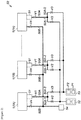
- FIG 2 is a block diagram of an alternative vacuum exhaust system.
- the vacuum exhaust system S2 shown in Figure 2 has a structure comprising a plurality of chambers 1 (1A, 1B, ... 1n).
- the vacuum exhaust system which exhausts the gases from the plurality of chambers is described in, for example, Patent Reference 1 and Patent Reference 2.
- the vacuum exhaust system S2 shown in Figure 2 has a first channel 50A and second channel 50B as the channels through which gas is exhausted from the chamber 1 (1A).
- a turbomolecular pump 51 which functions as a gas exhaust means for the gas molecular flow region is fitted into the upstream end of the first channel 50A.
- This first channel 50A is split into a first branch channel 50A-1 and second branch channel 50A-2 at a position downstream from the turbomolecular pump 51.
- a combination dry pump 52 is fitted to the downstream end of the first branch channel 50A-1 to exhaust the gas produced by the reaction with the process gas (the reaction product gas) in the first chamber 1 and the residuum of the process gas in the first chamber 1.
- a combination ⁇ dry pump 53 is fitted to the downstream end of the second branch channel 50B-2 to exhaust the gas used for the cleaning of the interior of the chamber 1.
- a dry pump 54 is fitted to the downstream end of the first channel 50A as the rough pump used when gas is initially exhausted from the chamber 1.
- the said combination dry pumps 52, 53 comprise a pump body P1 such as a known screw pump, which functions as a gas exhaust means in the viscous flow region of the gas, and a so-called mechanical booster pump P2 which functions as a means of increasing the exhaustion rate in the pressure region in which the exhaustion rate of the pump body P1 is lower.
- a pump body P1 such as a known screw pump, which functions as a gas exhaust means in the viscous flow region of the gas
- a so-called mechanical booster pump P2 which functions as a means of increasing the exhaustion rate in the pressure region in which the exhaustion rate of the pump body P1 is lower.
- valve 4 in the second channel 50B and valve V3 of the second branch channel 50A-2 are closed, and the valve V1 of the first channel 50A and valve V2 of the first branch channel 50A-1 are open, so that exhaustion of gas through second channel 50B and through second branch channel 50A-2 is disabled and exhaustion of gas through the first branch channel 50A-1 is enabled.
- the gas (reaction product gas and residuum process gas) in chamber 1 is exhausted through the first channel 50A (using the first branch channel 50A-1) by the exhausting action of turbomolecular pump 51 and dry pump 52.
- valve 4 in the second channel 50B and valve 2 of the first branch channel 50A-1 are closed, and the valve 1 of the first channel 50A and valve 3 of the second branch channel 50A-2 are open, so that exhaustion of gas through second channel 50B and through first branch channel 50A-1 is disabled and exhaustion of gas through the second branch channel 50A-2 is enabled.
- cleaning gas in chamber 1 and the turbomolecular pump 52 is exhausted through the first channel 50A (using the second branch channel 50A-2) by the exhausting action of the dry pump 53.
- valve V2 and V3 are located immediately before, respectively, dry pump 52 and dry pump 53, the first channel 50A and second channel 52B coexist from the beginning to the end of the exhaust system as the exhaust system from the chambers 1 to dry pumps 52, 53 and 54 etc, there are the problems that the overall structure of the vacuum exhaust system S is complex and the cost is higher as a consequence.
- CN 101922437 discloses a vacuum device comprising a plurality of pumping units for evacuating a plurality of chambers.
- the vacuum device comprises a plurality of high vacuum pumps such as turbo pumps and a plurality of lower vacuum pumps acting as backing pumps.
- There is a common pipeline and various valves between the backing pumps and turbo pumps allowing only a subset of the backing pumps to be used to provide the lower pressure at the output of the turbo pumps during high vacuum operation and allowing all of them to be used when evacuating the chambers initially.
- WO2006/097679 discloses a vacuum pumping arrangement for evacuating a chamber that comprises a plurality of booster and backing pumps.
- booster pumps are isolated from the gas being pumped, so that they operate at full speed and are not affected by the higher pressures. When a certain vacuum is reached these previously isolated booster pump(s) are connected such that all pumps are used.
- GB2437968 discloses a plurality of molecular and booster pumps.
- the present invention which was made in order to solve the said problems, has the aim of providing an appropriate vacuum exhaust system intended as a simpler structure of the overall vacuum exhaust system and also to reduce its cost.
- a first aspect provides a vacuum exhaust system according to claim 1.
- the present invention is also preferably characterised in that it has a third pump which functions as a means of increasing the exhaust rate in the pressure region in which the exhaust rate of the said second pump is lower, and in that the said third pump is fitted to any of the said plurality of branch channels
- the said second pump may be fitted to each of the said selection channels and a said second pump fitted to any one of the said selection channels may be used during rough pumping when gas is exhausted from the said chamber and, apart from rough pumping, the said second pumps fitted to the other two said selection channels may be used as backup pumps in an immediately-usable standby state.
- the present invention may also be characterised in that when the said third pumps are fitted in the vicinity of the said first pumps, for the said plurality branch channels, the length of pipe for the short distance from the said first pumps to the said third pumps may be larger in diameter than the rest of the pipes of the said plurality of branch channels.
- the present invention is also the said channel switching-valve used in the said vacuum exhaust system.
- the specific structure of the vacuum exhaust system is such that, as described above, the structure used for the channels is one in which the main channel is formed from a confluence of a plurality of branch channels and this main channel is connected to a plurality of selection channels by a channel-switching valve and any one of the said plurality of selection channels is caused to communicate with the main channel by the said channel-switching valve.
- the plurality of branch channels is made into a single channel by the confluence pipe and channel-switching valve and in that the valves (valve V2 and valve V3 in Figure 2 ) immediately before the second pumps (dry pump 52 and dry pump 53 in Figure 2 ) in the system S2 , are unified as a single channel-switching valve so that the total number of valves is reduced, it is possible to provide an appropriate vacuum exhaust system achieving an overall simplification of the structure of the vacuum exhaust system with reduction in cost.
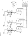
- FIG. 1 is a block drawing of one embodiment of the vacuum exhaust system according to the invention
- the vacuum exhaust system S1 shown in this figure has a structure of a system which exhausts gas from a plurality of chambers 1 (1A, 1B, ...1n).
- the vacuum exhaust system S1 shown in Figure 1 is furnished with an exhaust system component which exhausts gas from the first chamber (1A) and which, as shown in the figure, comprises 2 branch channels 2 (2A, 2B) which exhaust gas from the chamber 1 (1A), a main channel 3 in the form of a confluence of the 2 branch channels 2, channel on-off valves 4 fitted one for each of the 2 branch channels 2, a channel-switching valve 6 which connects main channel 2 and 3 selection channels 5 (5A, 5B, 5C) and which allows any one of the selection channels 5 to communicate with the main channel 3, a first pump 7 which functions as a gas exhaustion means in the molecular flow region of the gas, second pumps 8 (8A, 8B, 8C) which function as gas exhaustion means in the viscous flow region of the gas, and a third pump 9 which functions as a means of increasing the exhaustion rate in the pressure region where the exhaustion rate of the second pumps 8 is lower.
- the third pump 9 may be omitted.
- a first pump 7 and third pump 9 are fitted to a single branch channel 2 (2A) and one second pump 8 is fitted to each of the selection channels 5 (5A, 5B, 5C).
- Chamber 1 (1A) is a vessel which may be evacuated, such as the process chambers used in semiconductor production plants and the like, and specific processes using process gas and the like are performed in chamber 1 (1A). This also true of the other chambers 1 (1B, ...1n).
- Each of the 2 branch channels 2 (2A, 2B) and main channel 3 are formed from pipes and, in particular, the size (diameter) of the structural pipes of branch channel 2 (2A) to which the first pump 7 and third pump 9 are fitted vary according to location.
- the branch channel 2 (2A) in the short length from the first pump 7 to the third pump 9 is formed from large-diameter pipes with low pipe resistance and the rest of the said branch channel 2 (2A) and main channel 3, apart from this length, is formed from small-diameter pipes.
- the pipes in the short length from the first pump 7 to the third pump 9 are formed from pipes of larger diameter than the rest of the piping of the plurality of branch channels 2.
- the gas that flows along branch channel 2 (2A) in particular is principally the residuum of the process gas used in chamber 1 and gas produced by reactions of the process gas (reaction product gas) in chamber 1.
- a wire heater is wound around the outer periphery of the pipes forming the branch channel 2 (2A) and main channel 3 and the heater thus wound heats these pipes, as a means of preventing the accumulation of such gases in the branch channel 2 (2A) and main channel 3 as pressure falls.
- Both of the channel on-off valves 4 fitted to the 2 branch channels 2 (2A, 2B) are structured so that they open and close the corresponding branch channel 2, on the basis of open-close control signals F1 from a control device D according to the specific timing.
- the channel open-close valve 4 of the branch channel 2 (2B) When for example, gas is exhausted through the branch channel 2 (2A), in order to disable exhaustion of gas through branch channel 2 (2B) the channel open-close valve 4 of the branch channel 2 (2B) is closed, setting the branch channel 2 (2B) to a closed state, due to the output of open-close control signals F1 from the control device D to the channel open-close valve 4 of the branch channel 2 (2B), and in order to enable exhaustion of gas through branch channels 2 (2A), the channel open-close valve 4 of the branch channel 2 (2A) is opened, setting the branch channel 2 (2A) to an open state, due to the output of open-close control signals F1 from the control device D to the channel open-close valve 4 of the branch channel 2 (2A).
- the channel open-close valve 4 of the branch channel 2 (2A) is closed setting the branch channel 2 (2A) to a closed state, due to the output of open-close control signals F1 from the control device D to the channel open-close valve 4 of the branch channel 2 (2A), and in order to enable exhaustion of gas through branch channels 2 (2B), the channel open-close valve 4 of the branch channel 2 (2B) is opened, setting the branch channel 2 (2B) to an open state, due to the output of open-close control signals F1 from the control device D to the channel open-close valve 4 of the branch channel 2 (2B).
- each of the three selection channels 5 (5A, 5B, 5C) is connected to the outlet ports of the channel-switching valves 6 described below and downstream from this they merge with the selection channels 5 (5A, 5B, 5C) from the channel-switching valves 6 of the chambers 1 (1A, 1B, ... 1n) and are connected to the inlet ports of the second pumps 8 (8A, 8B, 8C).
- the structure of the channel-switching valves 6 of each of the chambers 1 (1A, 1B, ...1n) is, as described above, such that they have inlet ports for connection to the downstream end of the main channels 3 described above and outlet ports for connection with each of the upstream ends of the 3 selection channels 5 (5A, 5B, 5C) and the flow from the main channels 3 is diverted into one of the selection channels 5 (5A, 5B, 5C) by a switching operation within the channel-switching valves 6.
- the switching operation within the channel-switching valves 6 is performed at a specified timing, based on channel-switching signals F2 from the control device D.
- the structure of the first pump 7 has a gas inlet port and this gas inlet port is connected to the opening of chamber 1, so that gas may be fed into the chamber 1 through the said opening and inlet port.
- the structure of the first pump 7 has a gas exhaust port and this exhaust port 7B is connected to the upstream end of the branch channel 2 (2A), so that gas can be exhausted from the exhaust port through the branch channel 2 (2A), towards the downstream third pump 9.
- a controller C is fitted to the first pump 7 as a means of controlling and detecting the starting, stopping and rotational speed of the pump and other aspects of the state of the pump.
- a diagnostic circuit or diagnostic program is provided in the controller C which diagnoses whether there is any fault in the pump from the pump state detected and these diagnosis results R are sent from controller C to the control device D.
- a previously known turbomolecular pump can be used as this type of first pump 7 but it is not thus limited.
- a combination pump which has a structure comprising multiple stages of a first exhaust part functioning like a turbomolecular pump as a gas exhaustion means in the molecular flow region of the gas, and a second exhaust part functioning like a screw channel pump as a gas exhaustion means in the viscous flow region of the gas, and this combination pump may be used as the first pump 7.
- the third pump 9 has a structure such that it has a gas inlet port and outlet port and, since the inlet port and outlet port are connected downstream from the first pump 7 to the same branch channel 2 (2A) as the first pump 7, the gas fed through the branch channel 2 (2A) from the first pump 7 is exhausted again towards the downstream main channel 3.
- a controller C similar to that previously described for the first pump 7 may also be fitted to this third pump 9.
- a known mechanical booster pump can also be used as this third pump 9.
- a mechanical booster pump has a structure such that two peritrochoidal rotors rotate synchronously in opposite directions in a casing to exhaust gas and this can be used as a means of increasing exhaustion rate in pressure regions in which the exhaustion rate of the second pumps 8 (8A, 8B, 8C) is lower.
- All of the second pumps 8 (8A, 8B, 8C) have a gas inlet port and outlet port and the inlet port is connected to the downstream ends of the selection channels 5 (5A, 5B, 5C), so gas is fed in through the said downstream ends and inlet ports and the gas thus fed in can be exhausted from the outlet ports.
- a controller C similar to that previously described for the first pump 7 may also be fitted to each of the plurality of second pumps 8 (8A, 8B, 8C).
- a dry pump such as a known screw pump in which lubricating oil is used, may be used as these second pumps 8 functioning a means of exhausting gas in regions of gas viscosity .
- a second pump 8 (8A) fitted to one selection channel 5 (5A) is used as a rough pumping pump when gas is rough pumped from the chamber 1 and, other than during rough pumping, is in an immediately-usable standby state as backup pump for the second pumps 8 (8B, 8C) fitted to the other two said selection channels 5 (5B, 5C).
- one second pump 8 (8B) is used as a pump for the exhaustion of the process gas and gas produced by process gas reaction (reaction product gas) in the main chamber 1.
- the second pump 8 (8C) is used a pump for the exhaustion of gas used for the cleaning of the interior of chamber 1 and first pump 7 (cleaning gas).
- the control device D comprises, for example, a personal computer furnished with system programs and hardware resources for the performance of at least the functions shown as 1 to 5 below.
- Function 1 outputs control signals for the control of the pump state, such as starting, stopping, rotational speed and the like, to the controllers C of the first pump 7, second pumps 8 (8A, 8B, 8C) and third pump 9.
- Function 2 outputs open-close control signals F1, to perform opening and closing, to the channel open-close valves 4.
- Function 3 outputs channel-switching signals F2 to the channel-switching valves 6, to perform switching within the channel-switching valves 6 as described above.
- Function 4 receives the diagnosis results R (whether the pump is normal or not) made by the diagnostic circuit and diagnostic program in the controllers C in each of the first pump 7, second pumps 8 (8A, 8B, 8C) and third pump 9.
- Function 5 reviews the diagnosis results R received by function 4 and checks if a pump is faulty if diagnosed as abnormal.
- a process is carried out to output a channel-switching signal F2 (see 'Function 3' above) to the channel-switching valve 6 to cause the selection channel 5 (5A), which is fitted with the second pump 8 (8A) which is in standby status, as described above, to communicate with the main channel 2, and a process is carried out to output to the controller C of the second pump 8 (8A) a backup start signal F3 to switch the second pump 8(8A) from its standby state to a backup operational status.
- the second pump 8 (8C) be diagnosed as unusual.
- the said 'backup operational status' here means the second pump 8 (8A) is used as a backup pump in the place of the second pump 8 (8B or 8C) in which a fault has been diagnosed.
- the gas in the chamber 1 (reaction product gas and residuum of the process gas) are exhausted through the branch channel 2 (2A) and main channel 3.
- the first pump 7 functions as a gas exhaust means in the molecular flow region of the gas and the second pump 8 (8A) functions as a gas exhaust means in the viscous flow region of the gas.
- the third pump 9 functions as a means of increasing the exhaustion rate in the pressure region in which the exhaustion rate of the second pump 8 is lower.
- the channel open-close valve 4 of the branch channel 2 (2A) is opened and the channel open-close valve 4 of the other branch channel 2 (2B) is closed and also due to the switching operations in the channel-switching valve 6, the selection channel 5 (5C) communicates with the main channel 3. It follows that, due to the exhausting operation of the second pump 8 (8C), the cleaning gas in the chamber 1 and in the first pump 7 are exhausted through the branch channel 2 (2A), main channel 3 and selection channel 5 (5C).
- the system structure is such that, as described above, 2 branch channels 2 (2A, 2B) converge to form the main channel 3 and as this main channel 3 and three selection channels 5 (5A, 5B, 5C) are connected to channel-switching valve 6, one of the three selection channels 5 (5A, 5B, 5C) can be connected with the main channel 3 by this channel-switching valve 6.
- the description is of two branch channels 2 and three selection channels 5 but the present invention may also apply to a structure may also be one in which there are 3 or more branch channels 2 and/or a structure in which there are 3 or more selection channels 5.
Claims (5)
- Vakuumabsaugsystem zum Absaugen von Gas aus einer Kammer (1), mit:einer Mehrzahl von Zweigkanälen (2A, 2B) für das Absaugen des Gases aus der Kammer (1),einem Hauptkanal (3), der aus der Zusammenführung der Mehrzahl von Zweigkanälen (2A, 2B) gebildet ist,einem Kanal-Öffnungs-Schließ-Ventil (4), mit welchem jeder der Mehrzahl von Zweigkanälen ausgestattet ist,einer Mehrzahl von Selektionskanälen (5A, 5B, 5C),einer ersten Pumpe (7), die als Gasabsaugungsmittel im molekularen Strömungsbereich des Gases funktionieren,zweiten Pumpen (8), die als Gasabsaugungsmittel im viskosen Strömungsbereich des Gases funktionieren,wobei die erste Pumpe (7) irgendeinem der genannten Mehrzahl von Zweigkanälen (2A, 2B) zugeordnet ist,und die zweiten Pumpen (8) der Mehrzahl von Selektionskanälen (5A, 5B, 5C) zugeordnet sind,dadurch gekennzeichnet, dass das Vakuumabsaugsystem ein Kanalumschaltventil (6) aufweist, wobei der Hauptkanal (3) mit einem der Mehrzahl von Selektionskanälen (5A, 5B, 5C) über das Kanalumschaltventil (6) verbunden ist, und das Kanalumschaltventil zur Verbindung des Hauptkanals mit irgendeinem der Mehrzahl von Selektionskanälen konfiguriert ist.
- Vakuumabsaugsystem nach Anspruch 1, dadurch gekennzeichnet, dass es mit einer dritten Pumpe (9) ausgerüstet ist, die dafür konfiguriert ist, die Absaugrate in dem Druckbereich zu erhöhen, in welchem die Absaugrate der zweiten Pumpe (8) niedriger ist, und dass die dritte Pumpe (7) irgendeinem der Mehrzahl von Zweigkanälen zugeordnet ist.
- Vakuumabsaugsystem nach Anspruch 1 oder Anspruch 2, dadurch gekennzeichnet, dass die Selektionskanäle drei Selektionskanäle umfassen, wobei eine jeweilige der genannten zweiten Pumpen jedem der Selektionskanäle zugeordnet ist, wobei das Vakuumabsaugsystem so konfiguriert ist, dass eine der zweiten Pumpen zum Grobauspumpen der genannten Kammer konfiguriert ist, wenn Gas abgesaugt wird, und dass die genannte zweite Pumpe in einem sofort nutzbaren Bereitschaftszustand gehalten wird, um als Stützpumpe für die beiden anderen der genannten zweiten Pumpen benutzt zu werden, die den beiden anderen der Selektionskanäle zugeordnet sind, wenn sie sich nicht im Betrieb für das Grobauspumpen befindet.
- Vakuumabsaugsystem nach Anspruch 2, dadurch gekennzeichnet, dass die dritte Pumpe in der Nähe der ersten Pumpe angeordnet ist, und dass in der genannten Mehrzahl von Zweigkanälen das Rohr in der kurzen Länge von der ersten Pumpe zu der dritten Pumpe von größerem Durchmesser ist als der Rest der Rohre in der Mehrzahl von Zweigkanälen.
- Vakuumabsaugsystem zum Absaugen von Gas aus einer ersten Kammer (1) und mindestens einer weiteren Kammer (1), wobei das Vakuumabsaugsystem aufweist:ein Vakuumabsaugsystem nach irgendeinem vorhergehenden Anspruch zum Evakuieren der ersten Kammer,und mindestens eine weitere Mehrzahl von Zweigkanälen (2A, 2B) zum Absaugen des Gases aus mindestens einer weiteren Kammer (1),wobei mindestens ein weiterer Hauptkanal (3) aus der Zusammenführung der mindestens einen weiteren Mehrzahl von Zweigkanälen (2A, 2B) gebildet ist,ein Kanal-Öffnungs-Schließ-Ventil (4), das jedem der mindestens einen weiteren Mehrzahl von Zweigkanälen zugeordnet ist, undmindestens ein weiteres Kanalumschaltventil (6),wobei der mindestens eine weitere Hauptkanal (3) mit einem der Mehrzahl von Selektionskanälen (5A, 5B, 5C) über ein jeweiliges mindestens ein weiteres Kanalumschaltventil (6) verbunden ist, wobei das jeweilige Kanalumschaltventil dafür konfiguriert ist, den mindestens einen weiteren Hauptkanal mit irgendeinem der Mehrzahl von Selektionskanälen zu verbinden,mindestens einer weiteren ersten Pumpe (7), die als Gasabsaugungsmittel in dem molekularen Strömungsbereich des Gases zum Absaugen der mindestens einen weiteren Kammer funktioniert, wobei die mindestens eine weitere erste Pumpe (7) einem jeweiligen der mindestens einen weiteren Mehrzahl von Zweigkanälen (2A, 2B) zugeordnet ist.
Applications Claiming Priority (2)
| Application Number | Priority Date | Filing Date | Title |
|---|---|---|---|
| GB1500133.2A GB2533933A (en) | 2015-01-06 | 2015-01-06 | Improvements in or relating to vacuum pumping arrangements |
| PCT/GB2016/050019 WO2016110695A1 (en) | 2015-01-06 | 2016-01-06 | Vacuum exhaust system and channel-switching valve used in this vacuum exhaust system |
Publications (2)
| Publication Number | Publication Date |
|---|---|
| EP3247907A1 EP3247907A1 (de) | 2017-11-29 |
| EP3247907B1 true EP3247907B1 (de) | 2019-05-01 |
Family
ID=55129989
Family Applications (2)
| Application Number | Title | Priority Date | Filing Date |
|---|---|---|---|
| EP16700506.5A Active EP3247907B1 (de) | 2015-01-06 | 2016-01-06 | Vakuumabgassystem und in diesem vakuumabgassystem verwendetes kanalschaltventil |
| EP16700505.7A Active EP3243005B1 (de) | 2015-01-06 | 2016-01-06 | Verbesserungen an oder im zusammenhang mit vakuumpumpanordnungen |
Family Applications After (1)
| Application Number | Title | Priority Date | Filing Date |
|---|---|---|---|
| EP16700505.7A Active EP3243005B1 (de) | 2015-01-06 | 2016-01-06 | Verbesserungen an oder im zusammenhang mit vakuumpumpanordnungen |
Country Status (8)
| Country | Link |
|---|---|
| US (2) | US10309401B2 (de) |
| EP (2) | EP3247907B1 (de) |
| JP (2) | JP2018503027A (de) |
| KR (2) | KR20170102256A (de) |
| CN (2) | CN107110162B (de) |
| GB (2) | GB2533933A (de) |
| SG (1) | SG11201705287WA (de) |
| WO (2) | WO2016110694A1 (de) |
Cited By (1)
| Publication number | Priority date | Publication date | Assignee | Title |
|---|---|---|---|---|
| GB2584881A (en) * | 2019-06-19 | 2020-12-23 | Edwards Vacuum Llc | Multiple vacuum chamber exhaust system and method of evacuating multiple chambers |
Families Citing this family (20)
| Publication number | Priority date | Publication date | Assignee | Title |
|---|---|---|---|---|
| JP5808454B1 (ja) * | 2014-04-25 | 2015-11-10 | 株式会社日立国際電気 | 基板処理装置、半導体装置の製造方法、プログラムおよび記録媒体 |
| KR102154082B1 (ko) * | 2014-05-30 | 2020-09-09 | 가부시키가이샤 에바라 세이사꾸쇼 | 진공 배기 시스템 |
| GB201620225D0 (en) * | 2016-11-29 | 2017-01-11 | Edwards Ltd | Vacuum pumping arrangement |
| GB2561899B (en) * | 2017-04-28 | 2020-11-04 | Edwards Ltd | Vacuum pumping system |
| GB2564399A (en) * | 2017-07-06 | 2019-01-16 | Edwards Ltd | Improvements in or relating to pumping line arrangements |
| DE102017214687A1 (de) * | 2017-08-22 | 2019-02-28 | centrotherm international AG | Behandlungsvorrichtung für Substrate und Verfahren zum Betrieb einer solchen Behandlungsvorrichtung |
| CN107799445A (zh) * | 2017-11-01 | 2018-03-13 | 德淮半导体有限公司 | 用于半导体工艺腔的泵系统 |
| GB201718752D0 (en) * | 2017-11-13 | 2017-12-27 | Edwards Ltd | Vacuum and abatement systems |
| CN108486543A (zh) * | 2018-03-02 | 2018-09-04 | 惠科股份有限公司 | 基板成膜机台及使用方法 |
| WO2020069206A1 (en) * | 2018-09-28 | 2020-04-02 | Lam Research Corporation | Vacuum pump protection against deposition byproduct buildup |
| CN109185705B (zh) * | 2018-10-15 | 2024-04-16 | 苏州精濑光电有限公司 | 设备的吸真空气路系统 |
| GB2579360A (en) * | 2018-11-28 | 2020-06-24 | Edwards Ltd | Multiple chamber vacuum exhaust system |
| GB2581503A (en) * | 2019-02-20 | 2020-08-26 | Edwards Ltd | Vacuum pumping |
| CN110435190A (zh) * | 2019-06-26 | 2019-11-12 | 中复连众风电科技有限公司 | 具有抽真空单元的模具真空加热设备 |
| KR102329548B1 (ko) * | 2019-10-17 | 2021-11-24 | 무진전자 주식회사 | 챔버 배기량 자동 조절 시스템 |
| GB2592346B (en) * | 2020-01-09 | 2022-11-02 | Edwards Ltd | Vacuum pump and vacuum pump set for evacuating a semiconductor processing chamber |
| GB2592043A (en) * | 2020-02-13 | 2021-08-18 | Edwards Ltd | Axial flow vacuum pump |
| FR3112177B1 (fr) * | 2020-07-09 | 2022-07-08 | Pfeiffer Vacuum | Ligne de vide et procédé de contrôle d’une ligne de vide |
| FR3112086B1 (fr) * | 2020-07-09 | 2022-07-08 | Pfeiffer Vacuum | Dispositif de traitement des gaz et ligne de vide |
| GB2606193B (en) * | 2021-04-29 | 2023-09-06 | Edwards Ltd | A valve module for a vacuum pumping system |
Family Cites Families (33)
| Publication number | Priority date | Publication date | Assignee | Title |
|---|---|---|---|---|
| US4021898A (en) * | 1976-05-20 | 1977-05-10 | Timex Corporation | Method of adjusting the frequency of vibration of piezoelectric resonators |
| JPS564069A (en) | 1979-06-22 | 1981-01-16 | Mitsubishi Electric Corp | Test of semiconductor device |
| US5010035A (en) * | 1985-05-23 | 1991-04-23 | The Regents Of The University Of California | Wafer base for silicon carbide semiconductor device |
| JPH07107388B2 (ja) | 1987-12-16 | 1995-11-15 | 株式会社日立製作所 | 複数真空容器の排気方法 |
| JPH02185681A (ja) * | 1989-01-11 | 1990-07-20 | Mitsubishi Electric Corp | 真空排気装置 |
| JPH03258976A (ja) * | 1990-03-08 | 1991-11-19 | Mitsubishi Electric Corp | 真空装置における真空の再生方法 |
| US5733104A (en) * | 1992-12-24 | 1998-03-31 | Balzers-Pfeiffer Gmbh | Vacuum pump system |
| GB9614849D0 (en) * | 1996-07-15 | 1996-09-04 | Boc Group Plc | Processes for the scubbing of noxious substances |
| US6277347B1 (en) * | 1997-02-24 | 2001-08-21 | Applied Materials, Inc. | Use of ozone in process effluent abatement |
| JP4112659B2 (ja) * | 1997-12-01 | 2008-07-02 | 大陽日酸株式会社 | 希ガスの回収方法及び装置 |
| US6383300B1 (en) * | 1998-11-27 | 2002-05-07 | Tokyo Electron Ltd. | Heat treatment apparatus and cleaning method of the same |
| TW482871B (en) * | 1999-03-05 | 2002-04-11 | Tadahiro Ohmi | Vacuum device |
| JP2004218648A (ja) * | 1999-03-05 | 2004-08-05 | Tadahiro Omi | 真空装置 |
| JP2003083248A (ja) * | 2001-09-06 | 2003-03-19 | Ebara Corp | 真空排気システム |
| JP4180265B2 (ja) * | 2001-10-31 | 2008-11-12 | 株式会社アルバック | 真空排気装置の運転方法 |
| DE10159835B4 (de) * | 2001-12-06 | 2012-02-23 | Pfeiffer Vacuum Gmbh | Vakuumpumpsystem |
| US7819646B2 (en) * | 2002-10-14 | 2010-10-26 | Edwards Limited | Rotary piston vacuum pump with washing installation |
| US6761135B1 (en) * | 2003-08-27 | 2004-07-13 | Bryon Edward Becktold | Multipurpose assembly |
| US7278831B2 (en) * | 2003-12-31 | 2007-10-09 | The Boc Group, Inc. | Apparatus and method for control, pumping and abatement for vacuum process chambers |
| GB0505500D0 (en) * | 2005-03-17 | 2005-04-27 | Boc Group Plc | Vacuum pumping arrangement |
| US20070189356A1 (en) * | 2006-02-13 | 2007-08-16 | Jonathan Pettit | Exhaust buildup monitoring in semiconductor processing |
| GB2437968A (en) * | 2006-05-12 | 2007-11-14 | Boc Group Plc | Vacuum pumping arrangement for evacuating a plurality of process chambers |
| GB0615722D0 (en) * | 2006-08-08 | 2006-09-20 | Boc Group Plc | Apparatus for conveying a waste stream |
| US20090242046A1 (en) * | 2008-03-31 | 2009-10-01 | Benjamin Riordon | Valve module |
| JP2010161150A (ja) * | 2009-01-07 | 2010-07-22 | Shimadzu Corp | ガス排気ライン切り換え機構およびガス排気ライン切り換え方法 |
| JP2010167338A (ja) * | 2009-01-20 | 2010-08-05 | Renesas Electronics Corp | 真空処理装置及び真空処理方法 |
| CN102713287B (zh) * | 2009-12-28 | 2015-04-15 | 株式会社爱发科 | 真空排气装置、真空排气方法及基板处理装置 |
| CN101922437B (zh) * | 2010-08-05 | 2012-05-23 | 友达光电股份有限公司 | 真空设备 |
| KR101427726B1 (ko) * | 2011-12-27 | 2014-08-07 | 가부시키가이샤 히다치 고쿠사이 덴키 | 기판 처리 장치 및 반도체 장치의 제조 방법 |
| KR101427719B1 (ko) * | 2012-07-16 | 2014-09-30 | (주)트리플코어스코리아 | 반도체 공정 펌프 및 배기라인의 부산물 제어 방법 |
| JP5808454B1 (ja) * | 2014-04-25 | 2015-11-10 | 株式会社日立国際電気 | 基板処理装置、半導体装置の製造方法、プログラムおよび記録媒体 |
| KR102154082B1 (ko) * | 2014-05-30 | 2020-09-09 | 가부시키가이샤 에바라 세이사꾸쇼 | 진공 배기 시스템 |
| JP6522892B2 (ja) * | 2014-05-30 | 2019-05-29 | 株式会社荏原製作所 | 真空排気システム |
-
2015
- 2015-01-06 GB GB1500133.2A patent/GB2533933A/en not_active Withdrawn
-
2016
- 2016-01-06 KR KR1020177018523A patent/KR20170102256A/ko unknown
- 2016-01-06 WO PCT/GB2016/050018 patent/WO2016110694A1/en active Application Filing
- 2016-01-06 WO PCT/GB2016/050019 patent/WO2016110695A1/en active Application Filing
- 2016-01-06 CN CN201680005146.2A patent/CN107110162B/zh active Active
- 2016-01-06 US US15/541,085 patent/US10309401B2/en active Active
- 2016-01-06 US US15/541,083 patent/US20170350395A1/en not_active Abandoned
- 2016-01-06 JP JP2017553464A patent/JP2018503027A/ja active Pending
- 2016-01-06 EP EP16700506.5A patent/EP3247907B1/de active Active
- 2016-01-06 KR KR1020177018524A patent/KR102504078B1/ko active IP Right Grant
- 2016-01-06 EP EP16700505.7A patent/EP3243005B1/de active Active
- 2016-01-06 SG SG11201705287WA patent/SG11201705287WA/en unknown
- 2016-01-06 CN CN201680005140.5A patent/CN107110161B/zh active Active
- 2016-01-06 GB GB1600201.6A patent/GB2536336B/en not_active Expired - Fee Related
- 2016-01-06 JP JP2017553465A patent/JP6924147B2/ja active Active
Non-Patent Citations (1)
| Title |
|---|
| None * |
Cited By (2)
| Publication number | Priority date | Publication date | Assignee | Title |
|---|---|---|---|---|
| GB2584881A (en) * | 2019-06-19 | 2020-12-23 | Edwards Vacuum Llc | Multiple vacuum chamber exhaust system and method of evacuating multiple chambers |
| GB2584881B (en) * | 2019-06-19 | 2022-01-05 | Edwards Vacuum Llc | Multiple vacuum chamber exhaust system and method of evacuating multiple chambers |
Also Published As
| Publication number | Publication date |
|---|---|
| KR20170102256A (ko) | 2017-09-08 |
| SG11201705287WA (en) | 2017-07-28 |
| GB2533933A (en) | 2016-07-13 |
| CN107110162A (zh) | 2017-08-29 |
| US10309401B2 (en) | 2019-06-04 |
| CN107110162B (zh) | 2019-07-16 |
| JP6924147B2 (ja) | 2021-08-25 |
| GB2536336B (en) | 2018-06-20 |
| EP3247907A1 (de) | 2017-11-29 |
| GB201600201D0 (en) | 2016-02-17 |
| WO2016110695A1 (en) | 2016-07-14 |
| KR20170102257A (ko) | 2017-09-08 |
| CN107110161B (zh) | 2019-09-13 |
| JP2018501437A (ja) | 2018-01-18 |
| EP3243005B1 (de) | 2019-08-28 |
| US20180003178A1 (en) | 2018-01-04 |
| WO2016110694A1 (en) | 2016-07-14 |
| US20170350395A1 (en) | 2017-12-07 |
| JP2018503027A (ja) | 2018-02-01 |
| KR102504078B1 (ko) | 2023-02-24 |
| GB2536336A (en) | 2016-09-14 |
| EP3243005A1 (de) | 2017-11-15 |
| CN107110161A (zh) | 2017-08-29 |
Similar Documents
| Publication | Publication Date | Title |
|---|---|---|
| EP3247907B1 (de) | Vakuumabgassystem und in diesem vakuumabgassystem verwendetes kanalschaltventil | |
| TWI745498B (zh) | 真空泵之配置及製造總成 | |
| CN113039364B (zh) | 多室真空排气系统 | |
| CN105552001B (zh) | 一种真空系统 | |
| WO2007119077A3 (en) | Vacuum pumping system | |
| GB2500610A (en) | Apparatus to supply purge gas to a multistage vacuum pump | |
| CN114645265B (zh) | 抽真空系统、半导体工艺设备及抽真空的方法 | |
| CN105257580A (zh) | 用于反应气压缩机的控制系统及方法 | |
| TW202117059A (zh) | 多個真空腔室排出系統及用以抽空多個腔室之方法 | |
| JP5102068B2 (ja) | 多段真空ポンプ | |
| CN205315325U (zh) | 用于反应气压缩机的控制系统 | |
| JP2014159749A (ja) | 減圧システム | |
| JP2017089512A (ja) | 真空排気装置 | |
| CN215862898U (zh) | 一种进气装置及系统 | |
| JP2001345270A (ja) | 半導体製造装置用排ガス処理装置及びその運転方法 | |
| EP3690205B1 (de) | Dampfturbinensystem | |
| CN115637420A (zh) | 用于双腔半导体设备的排气管路以及双腔半导体设备 | |
| JP2010278182A (ja) | 排ガス処理装置及び排ガス処理方法 | |
| CN115210468A (zh) | 冗余泵送系统和利用此泵送系统的泵送方法 | |
| JP2014226655A (ja) | 遠心機 |
Legal Events
| Date | Code | Title | Description |
|---|---|---|---|
| STAA | Information on the status of an ep patent application or granted ep patent |
Free format text: STATUS: THE INTERNATIONAL PUBLICATION HAS BEEN MADE |
|
| PUAI | Public reference made under article 153(3) epc to a published international application that has entered the european phase |
Free format text: ORIGINAL CODE: 0009012 |
|
| STAA | Information on the status of an ep patent application or granted ep patent |
Free format text: STATUS: REQUEST FOR EXAMINATION WAS MADE |
|
| 17P | Request for examination filed |
Effective date: 20170724 |
|
| AK | Designated contracting states |
Kind code of ref document: A1 Designated state(s): AL AT BE BG CH CY CZ DE DK EE ES FI FR GB GR HR HU IE IS IT LI LT LU LV MC MK MT NL NO PL PT RO RS SE SI SK SM TR |
|
| AX | Request for extension of the european patent |
Extension state: BA ME |
|
| DAV | Request for validation of the european patent (deleted) | ||
| DAX | Request for extension of the european patent (deleted) | ||
| REG | Reference to a national code |
Ref country code: DE Ref legal event code: R079 Ref document number: 602016013157 Country of ref document: DE Free format text: PREVIOUS MAIN CLASS: F04C0025020000 Ipc: F04C0023000000 |
|
| GRAP | Despatch of communication of intention to grant a patent |
Free format text: ORIGINAL CODE: EPIDOSNIGR1 |
|
| STAA | Information on the status of an ep patent application or granted ep patent |
Free format text: STATUS: GRANT OF PATENT IS INTENDED |
|
| INTG | Intention to grant announced |
Effective date: 20181130 |
|
| RIC1 | Information provided on ipc code assigned before grant |
Ipc: F04C 25/02 20060101ALI20181116BHEP Ipc: F04C 23/00 20060101AFI20181116BHEP |
|
| GRAS | Grant fee paid |
Free format text: ORIGINAL CODE: EPIDOSNIGR3 |
|
| GRAA | (expected) grant |
Free format text: ORIGINAL CODE: 0009210 |
|
| STAA | Information on the status of an ep patent application or granted ep patent |
Free format text: STATUS: THE PATENT HAS BEEN GRANTED |
|
| AK | Designated contracting states |
Kind code of ref document: B1 Designated state(s): AL AT BE BG CH CY CZ DE DK EE ES FI FR GB GR HR HU IE IS IT LI LT LU LV MC MK MT NL NO PL PT RO RS SE SI SK SM TR |
|
| REG | Reference to a national code |
Ref country code: GB Ref legal event code: FG4D |
|
| REG | Reference to a national code |
Ref country code: CH Ref legal event code: EP Ref country code: AT Ref legal event code: REF Ref document number: 1127297 Country of ref document: AT Kind code of ref document: T Effective date: 20190515 |
|
| REG | Reference to a national code |
Ref country code: DE Ref legal event code: R096 Ref document number: 602016013157 Country of ref document: DE |
|
| REG | Reference to a national code |
Ref country code: IE Ref legal event code: FG4D |
|
| REG | Reference to a national code |
Ref country code: NL Ref legal event code: MP Effective date: 20190501 |
|
| REG | Reference to a national code |
Ref country code: LT Ref legal event code: MG4D |
|
| PG25 | Lapsed in a contracting state [announced via postgrant information from national office to epo] |
Ref country code: AL Free format text: LAPSE BECAUSE OF FAILURE TO SUBMIT A TRANSLATION OF THE DESCRIPTION OR TO PAY THE FEE WITHIN THE PRESCRIBED TIME-LIMIT Effective date: 20190501 Ref country code: NO Free format text: LAPSE BECAUSE OF FAILURE TO SUBMIT A TRANSLATION OF THE DESCRIPTION OR TO PAY THE FEE WITHIN THE PRESCRIBED TIME-LIMIT Effective date: 20190801 Ref country code: ES Free format text: LAPSE BECAUSE OF FAILURE TO SUBMIT A TRANSLATION OF THE DESCRIPTION OR TO PAY THE FEE WITHIN THE PRESCRIBED TIME-LIMIT Effective date: 20190501 Ref country code: HR Free format text: LAPSE BECAUSE OF FAILURE TO SUBMIT A TRANSLATION OF THE DESCRIPTION OR TO PAY THE FEE WITHIN THE PRESCRIBED TIME-LIMIT Effective date: 20190501 Ref country code: NL Free format text: LAPSE BECAUSE OF FAILURE TO SUBMIT A TRANSLATION OF THE DESCRIPTION OR TO PAY THE FEE WITHIN THE PRESCRIBED TIME-LIMIT Effective date: 20190501 Ref country code: LT Free format text: LAPSE BECAUSE OF FAILURE TO SUBMIT A TRANSLATION OF THE DESCRIPTION OR TO PAY THE FEE WITHIN THE PRESCRIBED TIME-LIMIT Effective date: 20190501 Ref country code: PT Free format text: LAPSE BECAUSE OF FAILURE TO SUBMIT A TRANSLATION OF THE DESCRIPTION OR TO PAY THE FEE WITHIN THE PRESCRIBED TIME-LIMIT Effective date: 20190901 Ref country code: SE Free format text: LAPSE BECAUSE OF FAILURE TO SUBMIT A TRANSLATION OF THE DESCRIPTION OR TO PAY THE FEE WITHIN THE PRESCRIBED TIME-LIMIT Effective date: 20190501 Ref country code: FI Free format text: LAPSE BECAUSE OF FAILURE TO SUBMIT A TRANSLATION OF THE DESCRIPTION OR TO PAY THE FEE WITHIN THE PRESCRIBED TIME-LIMIT Effective date: 20190501 |
|
| PG25 | Lapsed in a contracting state [announced via postgrant information from national office to epo] |
Ref country code: RS Free format text: LAPSE BECAUSE OF FAILURE TO SUBMIT A TRANSLATION OF THE DESCRIPTION OR TO PAY THE FEE WITHIN THE PRESCRIBED TIME-LIMIT Effective date: 20190501 Ref country code: LV Free format text: LAPSE BECAUSE OF FAILURE TO SUBMIT A TRANSLATION OF THE DESCRIPTION OR TO PAY THE FEE WITHIN THE PRESCRIBED TIME-LIMIT Effective date: 20190501 Ref country code: GR Free format text: LAPSE BECAUSE OF FAILURE TO SUBMIT A TRANSLATION OF THE DESCRIPTION OR TO PAY THE FEE WITHIN THE PRESCRIBED TIME-LIMIT Effective date: 20190802 Ref country code: BG Free format text: LAPSE BECAUSE OF FAILURE TO SUBMIT A TRANSLATION OF THE DESCRIPTION OR TO PAY THE FEE WITHIN THE PRESCRIBED TIME-LIMIT Effective date: 20190801 |
|
| REG | Reference to a national code |
Ref country code: AT Ref legal event code: MK05 Ref document number: 1127297 Country of ref document: AT Kind code of ref document: T Effective date: 20190501 |
|
| PG25 | Lapsed in a contracting state [announced via postgrant information from national office to epo] |
Ref country code: IS Free format text: LAPSE BECAUSE OF FAILURE TO SUBMIT A TRANSLATION OF THE DESCRIPTION OR TO PAY THE FEE WITHIN THE PRESCRIBED TIME-LIMIT Effective date: 20190901 |
|
| PG25 | Lapsed in a contracting state [announced via postgrant information from national office to epo] |
Ref country code: CZ Free format text: LAPSE BECAUSE OF FAILURE TO SUBMIT A TRANSLATION OF THE DESCRIPTION OR TO PAY THE FEE WITHIN THE PRESCRIBED TIME-LIMIT Effective date: 20190501 Ref country code: SK Free format text: LAPSE BECAUSE OF FAILURE TO SUBMIT A TRANSLATION OF THE DESCRIPTION OR TO PAY THE FEE WITHIN THE PRESCRIBED TIME-LIMIT Effective date: 20190501 Ref country code: EE Free format text: LAPSE BECAUSE OF FAILURE TO SUBMIT A TRANSLATION OF THE DESCRIPTION OR TO PAY THE FEE WITHIN THE PRESCRIBED TIME-LIMIT Effective date: 20190501 Ref country code: AT Free format text: LAPSE BECAUSE OF FAILURE TO SUBMIT A TRANSLATION OF THE DESCRIPTION OR TO PAY THE FEE WITHIN THE PRESCRIBED TIME-LIMIT Effective date: 20190501 Ref country code: DK Free format text: LAPSE BECAUSE OF FAILURE TO SUBMIT A TRANSLATION OF THE DESCRIPTION OR TO PAY THE FEE WITHIN THE PRESCRIBED TIME-LIMIT Effective date: 20190501 Ref country code: RO Free format text: LAPSE BECAUSE OF FAILURE TO SUBMIT A TRANSLATION OF THE DESCRIPTION OR TO PAY THE FEE WITHIN THE PRESCRIBED TIME-LIMIT Effective date: 20190501 |
|
| REG | Reference to a national code |
Ref country code: DE Ref legal event code: R097 Ref document number: 602016013157 Country of ref document: DE |
|
| PG25 | Lapsed in a contracting state [announced via postgrant information from national office to epo] |
Ref country code: SM Free format text: LAPSE BECAUSE OF FAILURE TO SUBMIT A TRANSLATION OF THE DESCRIPTION OR TO PAY THE FEE WITHIN THE PRESCRIBED TIME-LIMIT Effective date: 20190501 Ref country code: IT Free format text: LAPSE BECAUSE OF FAILURE TO SUBMIT A TRANSLATION OF THE DESCRIPTION OR TO PAY THE FEE WITHIN THE PRESCRIBED TIME-LIMIT Effective date: 20190501 |
|
| PLBE | No opposition filed within time limit |
Free format text: ORIGINAL CODE: 0009261 |
|
| STAA | Information on the status of an ep patent application or granted ep patent |
Free format text: STATUS: NO OPPOSITION FILED WITHIN TIME LIMIT |
|
| PG25 | Lapsed in a contracting state [announced via postgrant information from national office to epo] |
Ref country code: TR Free format text: LAPSE BECAUSE OF FAILURE TO SUBMIT A TRANSLATION OF THE DESCRIPTION OR TO PAY THE FEE WITHIN THE PRESCRIBED TIME-LIMIT Effective date: 20190501 |
|
| 26N | No opposition filed |
Effective date: 20200204 |
|
| PG25 | Lapsed in a contracting state [announced via postgrant information from national office to epo] |
Ref country code: PL Free format text: LAPSE BECAUSE OF FAILURE TO SUBMIT A TRANSLATION OF THE DESCRIPTION OR TO PAY THE FEE WITHIN THE PRESCRIBED TIME-LIMIT Effective date: 20190501 |
|
| PG25 | Lapsed in a contracting state [announced via postgrant information from national office to epo] |
Ref country code: SI Free format text: LAPSE BECAUSE OF FAILURE TO SUBMIT A TRANSLATION OF THE DESCRIPTION OR TO PAY THE FEE WITHIN THE PRESCRIBED TIME-LIMIT Effective date: 20190501 |
|
| PG25 | Lapsed in a contracting state [announced via postgrant information from national office to epo] |
Ref country code: MC Free format text: LAPSE BECAUSE OF FAILURE TO SUBMIT A TRANSLATION OF THE DESCRIPTION OR TO PAY THE FEE WITHIN THE PRESCRIBED TIME-LIMIT Effective date: 20190501 |
|
| REG | Reference to a national code |
Ref country code: CH Ref legal event code: PL |
|
| REG | Reference to a national code |
Ref country code: BE Ref legal event code: MM Effective date: 20200131 |
|
| PG25 | Lapsed in a contracting state [announced via postgrant information from national office to epo] |
Ref country code: LU Free format text: LAPSE BECAUSE OF NON-PAYMENT OF DUE FEES Effective date: 20200106 |
|
| PG25 | Lapsed in a contracting state [announced via postgrant information from national office to epo] |
Ref country code: CH Free format text: LAPSE BECAUSE OF NON-PAYMENT OF DUE FEES Effective date: 20200131 Ref country code: LI Free format text: LAPSE BECAUSE OF NON-PAYMENT OF DUE FEES Effective date: 20200131 Ref country code: BE Free format text: LAPSE BECAUSE OF NON-PAYMENT OF DUE FEES Effective date: 20200131 |
|
| PG25 | Lapsed in a contracting state [announced via postgrant information from national office to epo] |
Ref country code: IE Free format text: LAPSE BECAUSE OF NON-PAYMENT OF DUE FEES Effective date: 20200106 |
|
| PG25 | Lapsed in a contracting state [announced via postgrant information from national office to epo] |
Ref country code: MT Free format text: LAPSE BECAUSE OF FAILURE TO SUBMIT A TRANSLATION OF THE DESCRIPTION OR TO PAY THE FEE WITHIN THE PRESCRIBED TIME-LIMIT Effective date: 20190501 Ref country code: CY Free format text: LAPSE BECAUSE OF FAILURE TO SUBMIT A TRANSLATION OF THE DESCRIPTION OR TO PAY THE FEE WITHIN THE PRESCRIBED TIME-LIMIT Effective date: 20190501 |
|
| PG25 | Lapsed in a contracting state [announced via postgrant information from national office to epo] |
Ref country code: MK Free format text: LAPSE BECAUSE OF FAILURE TO SUBMIT A TRANSLATION OF THE DESCRIPTION OR TO PAY THE FEE WITHIN THE PRESCRIBED TIME-LIMIT Effective date: 20190501 |
|
| REG | Reference to a national code |
Ref country code: DE Ref legal event code: R082 Ref document number: 602016013157 Country of ref document: DE Representative=s name: FLEUCHAUS & GALLO PARTNERSCHAFT MBB - PATENT- , DE Ref country code: DE Ref legal event code: R082 Ref document number: 602016013157 Country of ref document: DE Representative=s name: FLEUCHAUS & GALLO PARTNERSCHAFT MBB PATENTANWA, DE |
|
| PGFP | Annual fee paid to national office [announced via postgrant information from national office to epo] |
Ref country code: FR Payment date: 20230125 Year of fee payment: 8 |
|
| P01 | Opt-out of the competence of the unified patent court (upc) registered |
Effective date: 20230503 |
|
| PGFP | Annual fee paid to national office [announced via postgrant information from national office to epo] |
Ref country code: DE Payment date: 20240129 Year of fee payment: 9 Ref country code: GB Payment date: 20240129 Year of fee payment: 9 |