EP3243552B1 - Anlage für feuerlöschendes gas - Google Patents
Anlage für feuerlöschendes gas Download PDFInfo
- Publication number
- EP3243552B1 EP3243552B1 EP17178419.2A EP17178419A EP3243552B1 EP 3243552 B1 EP3243552 B1 EP 3243552B1 EP 17178419 A EP17178419 A EP 17178419A EP 3243552 B1 EP3243552 B1 EP 3243552B1
- Authority
- EP
- European Patent Office
- Prior art keywords
- fire
- sound absorption
- absorption material
- silencer
- extinguishing
- Prior art date
- Legal status (The legal status is an assumption and is not a legal conclusion. Google has not performed a legal analysis and makes no representation as to the accuracy of the status listed.)
- Active
Links
Images


Classifications
-
- A—HUMAN NECESSITIES
- A62—LIFE-SAVING; FIRE-FIGHTING
- A62C—FIRE-FIGHTING
- A62C99/00—Subject matter not provided for in other groups of this subclass
- A62C99/0009—Methods of extinguishing or preventing the spread of fire by cooling down or suffocating the flames
- A62C99/0018—Methods of extinguishing or preventing the spread of fire by cooling down or suffocating the flames using gases or vapours that do not support combustion, e.g. steam, carbon dioxide
-
- A—HUMAN NECESSITIES
- A62—LIFE-SAVING; FIRE-FIGHTING
- A62C—FIRE-FIGHTING
- A62C31/00—Delivery of fire-extinguishing material
- A62C31/02—Nozzles specially adapted for fire-extinguishing
-
- A—HUMAN NECESSITIES
- A62—LIFE-SAVING; FIRE-FIGHTING
- A62C—FIRE-FIGHTING
- A62C31/00—Delivery of fire-extinguishing material
- A62C31/28—Accessories for delivery devices, e.g. supports
-
- A—HUMAN NECESSITIES
- A62—LIFE-SAVING; FIRE-FIGHTING
- A62C—FIRE-FIGHTING
- A62C35/00—Permanently-installed equipment
- A62C35/58—Pipe-line systems
-
- A—HUMAN NECESSITIES
- A62—LIFE-SAVING; FIRE-FIGHTING
- A62C—FIRE-FIGHTING
- A62C35/00—Permanently-installed equipment
- A62C35/58—Pipe-line systems
- A62C35/68—Details, e.g. of pipes or valve systems
Definitions
- the present invention relates to a gas fire-extinguishing apparatus which ejects fire-extinguishing gas such as N 2 gas or a halide gas as a fire-extinguishing agent into a fire-extinguishing area such as a building, when a fire occurs, so that the fire is extinguished by decreasing an O 2 concentration within the fire-extinguishing area and more specifically, to the gas fire-extinguishing apparatus which can be suitably implemented to decrease a large sound occurring when the fire-extinguishing gas is ejected from an ejection head disposed within the fire-extinguishing area.
- fire-extinguishing gas such as N 2 gas or a halide gas as a fire-extinguishing agent into a fire-extinguishing area such as a building
- the gas fire-extinguishing apparatus is provided in various buildings wherein fire-extinguishing gas such as CO 2 gas, N 2 gas and a halide gas as a fire-extinguishing agent is ejected within a fire-extinguishing area so that the fire is extinguished by decreasing the O 2 concentration within the fire-extinguishing area.
- fire-extinguishing gas such as CO 2 gas, N 2 gas and a halide gas as a fire-extinguishing agent is ejected within a fire-extinguishing area so that the fire is extinguished by decreasing the O 2 concentration within the fire-extinguishing area.
- Fig. 16 is a perspective view illustrating the fire-extinguishing gas ejection section 1 used in the gas fire-extinguishing apparatus of the related art.
- the fire-extinguishing gas ejection section 1 includes an ejection head 3 ejecting high-pressure fire-extinguishing gas supplied from a fire-extinguishing gas supply source 2 when a fire occurs and a conduit pipe 4 to which the ejection head 3 is connected.
- the conduit pipe 4 has a main pipe 5 connected to the fire-extinguishing gas supply source 2, a diverging pipe 6 interposed in the main pipe 5 and a branch pipe 7 in which the fire-extinguishing gas is guided from the main pipe 5 by the diverging pipe 6 and to which the ejection head 3 is connected.
- the main pipe 5 is fastened to a base 8 and a bracket 9 fixed to a body of a building or the body thereof by a fastener 10 such as a U-bolt, and is disposed in a state where vibration and displacement of the ejection head 3 are suppressed (for example, Patent Literature 1)
- Patent Literature 1 Japanese Unexamined Patent Publication JP-A 8-173565 (1996 )
- German utility model DE20120671 describes a fire extinguishing system having nozzles connected to an extinguishing line.
- European patent application EP1151800 describe a silenced nozzle for discharge of a fire-extinguishing gas.
- United States patent US3672465 describes a gas exhaust silencer for use with pneumatic tools.
- An object of the invention is to provide a gas fire-extinguishing apparatus which can attenuate the sound caused by an ejection flow of fire-extinguishing gas from an ejection head.
- the invention provides a gas fire-extinguishing apparatus according to claim 1.
- high-pressure fire-extinguishing gas supplied from the fire-extinguishing gas supply source to the conduit pipe is ejected to space within the building via the ejection head.
- the silencer is disposed on the ejection head as described above, and thereby the occurrence of large ejection sound caused by the ejection flow of the fire-extinguishing gas ejected at high speed from the nozzle section of the ejection head can be prevented.
- the sound absorption material includes a first sound absorption material disposed at one end in the axial direction of the peripheral wall and a second sound absorption material disposed at the other end in the axial direction of the peripheral wall.
- the fire-extinguishing gas supplied from the branch pipe is gradually expanded with the decreased pressure by the first sound absorption material immediately after the nozzle hole and the flow speed thereof can be decreased.
- the fire-extinguishing gas is further expanded with the decreased pressure by the second sound absorption material immediately before the ejection and the flow speed thereof can be decreased. Accordingly, the occurrence of ejection sound caused by the ejection of the fire-extinguishing gas can be suppressed.
- the silencer further includes a third sound absorption material disposed between the first sound absorption material and the second sound absorption material.
- the third sound absorption material disposed between the first sound absorption material and the second sound absorption material since the third sound absorption material disposed between the first sound absorption material and the second sound absorption material, the sound vibration caused by the ejection flow of the fire-extinguishing gas is absorbed by the third sound absorption material and the occurrence of ejection sound caused by the ejection of the fire-extinguishing gas can be suppressed.
- the silencer Since the silencer is disposed on the ejection head, the occurrence of large ejection sound can be prevented even though the fire-extinguishing gas is ejected from the nozzle section of the ejection head when the fire occurs.
- the nozzle hole having the inner peripheral surface smoothly connecting the inner peripheral surface of the conduit pipe is formed in the ejection head, the occurrence of large ejection sound can be prevented even though the fire-extinguishing gas is ejected from the nozzle section of the ejection nozzle when the fire occurs.
- the silencer is disposed between the ejection head and the conduit pipe, the occurrence of large ejection sound can be prevented even though the fire-extinguishing gas is ejected from the nozzle section of the ejection nozzle when the fire occurs.
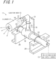
- Fig. 1 is a perspective view illustrating a fire-extinguishing gas ejection section 11 included in a gas fire-extinguishing apparatus according to an embodiment of the invention.
- the gas fire-extinguishing apparatus of the embodiment is disposed within a fire-extinguishing area of a building and includes an ejection head 13 having a nozzle section 12 ejecting high-pressure fire-extinguishing gas into a space within the fire-extinguishing area, a conduit pipe 14, to which the ejection head 13 is connected, and guides high-pressure fire-extinguishing gas to the ejection head 13, a fire-extinguishing gas supply source 15 supplying high-pressure inert gas to the conduit pipe 14, and a silencer 17 which is disposed on the ejection head 13 and attenuates sound generated due to ejection sound or the like by the ejection of the fire-extinguishing gas ejected from a nozzle hole 16 which is formed in the nozzle
- the fire-extinguishing gas is realized by an inert gas such as an N2 gas, or a CO2 gas, and an active gas such as a halide gas and such fire-extinguishing gas is ejected as a fire-extinguishing agent so that O2 concentration within the fire-extinguishing area is decreased and thereby the fire can be extinguished.
- an inert gas such as an N2 gas, or a CO2 gas
- an active gas such as a halide gas
- the fire-extinguishing gas ejection section 11 is constituted by the ejection head 13 and the silencer 17.
- the fire-extinguishing gas is supplied from the fire-extinguishing gas supply source 15 to the ejection head 13 via conduit pipe 14.
- the conduit pipe 14 includes a main pipe 23 connected to the fire-extinguishing gas supply source 15, a diverging pipe 18 interposed in the main pipe 23 and a branch pipe 19 connected to the diverging pipe 18, and the high-pressure fire-extinguishing gas is guided from the fire-extinguishing gas supply source 15 to the ejection head 13 via the conduit pipe 14.
- the conduit pipe 14 is fastened to a base 20 and a bracket 21 by a fastener 22 such as a U-bolt, and is disposed on a body of a building in a state where vibration and displacement thereof are suppressed.
- Fig. 2 is an enlarged cross-sectional view of the silencer 17.
- the silencer 17 includes a cylindrical peripheral wall 25, an end wall 26 which is formed at one end in an axial direction of the peripheral wall 25 to be perpendicular to the axis of the peripheral wall 25, a mounting section 27 detachably connected to the ejection head 13 at the other end in the axial direction of the peripheral wall 25, and a cylindrical sound absorption material 33 accommodated and mounted along an inner peripheral surface of the inside of the peripheral wall 25.
- a sound absorption material 33 may be configured by, for example, a laminate of two or more wire meshes.
- a gas ejection hole 34 is formed in the end wall 26 in the same axial direction.
- the silencer 17 configured as described above, is used, the sound vibration caused by the ejection flow of the fire-extinguishing gas ejected in high speed from the nozzle section 12 of the ejection head 13 is absorbed by the sound absorption material 33, and the fire-extinguishing gas is ejected from the gas ejection hole 34 to the outside. Accordingly, the occurrence of ejection sound caused by the ejection of the fire-extinguishing gas can be suppressed.
- Fig. 3 is an enlarged cross-sectional view illustrating a silencer 17a included in a gas fire-extinguishing apparatus.
- the silencer 17a includes a cylindrical peripheral wall 25, the end wall 26 which is formed at one end in the axial direction of the peripheral wall 25 to be perpendicular to the axis of the peripheral wall 25, the mounting section 27 in which the ejection head 13 is integrally formed at the other end in the axial direction of the peripheral wall 25, and an inner cylinder 29 which is disposed in a portion 28 of the nozzle section 12 facing a downstream side in a fire-extinguishing gas ejection direction in the nozzle section 12 of the ejection head 13.
- the inner cylinder 29 has a right cylinder section 31 in which a plurality of penetrating holes 30 are formed, and an end plate 32 formed at one end in the axial direction of the cylinder section 31 to be perpendicular to the axial direction of the cylinder section 31.
- the fire-extinguishing gas ejected at high speed from the nozzle section of the ejection head 13 impacts on the cylindrical end plate 32 of the inner cylinder 29, and is ejected from a plurality of penetrating holes 30 formed on the cylinder section 31, and then the fire-extinguishing gas is ejected to the outside from the gas ejection hole 34 formed in the end wall 26 via a space between the cylinder section 31 and the peripheral wall 25, and the occurrence of sound caused by ejection of the fire-extinguishing gas is suppressed.
- Fig. 4 is an enlarged cross-sectional view illustrating a silencer 17b included in a gas fire-extinguishing apparatus.
- the silencer 17b includes a cylindrical peripheral wall 35, an end wall 36 which is formed at one end in the axial direction of the peripheral wall 35 to be perpendicular to the axis of the peripheral wall 35, and a mounting section 37 detachably formed on the ejection head 13 at the other end in the axial direction of the peripheral wall 35.
- a plurality of vent holes 38 are formed in the end wall 36 so as to penetrate the end wall 36 in a thickness direction thereof.
- the silencer 17b accommodates a sound absorption material 40 in an inner space 39 defined by the peripheral wall 35, the end wall 36 and the mounting section 37.
- the sound absorption material 40 may be configured by a laminate of the two or more wire meshes.
- the fire-extinguishing gas ejected at high speed from the nozzle section 12 of the ejection head 13 impacts on the end wall 36 via a space within the peripheral wall 35 and is ejected from the plurality of vent holes 38 formed in the end wall 36 to the outside.
- the occurrence of large sound can also be prevented from occurring by the above-described configuration of the silencer.
- Fig. 5 is an enlarged cross-sectional view illustrating a silencer 17c included in a gas fire-extinguishing apparatus.
- the silencer 17 includes a cylindrical peripheral wall 41, an end wall 42 which is formed at one end in the axial direction of the peripheral wall 41 to be perpendicular to the axis of the peripheral wall 41, and a mounting section 43 detachably formed on the ejection head 13 at the other end in the axial direction of the peripheral wall 41.
- a plurality of vent holes 44 are formed in the peripheral wall 41 so as to penetrate the peripheral wall 41 in a thickness direction thereof.
- the silencer 17c configured as described above accommodates a sound absorption material 46 in an inner space 45 defined by the peripheral wall 41, the end wall 42 and the mounting section 43.
- the sound absorption material 46 may be configured by, for example, a laminate of two or more wire meshes.
- the fire-extinguishing gas ejected from the nozzle section 12 of the ejection head 13 impacts on the end wall 42 the flow speed thereof is attenuated, and the fire-extinguishing gas is ejected from a plurality of vent holes 44 formed in the peripheral wall 41 to the outside. Accordingly, the occurrence of large sound caused by the ejection of the fire-extinguishing gas can be prevented.
- Fig. 6 is a cross-sectional view illustrating an ejection head 50 of a gas fire-extinguishing apparatus
- Fig. 7 is a cross-sectional view explaining an effect of the ejection head 50 shown in Fig. 6 .
- portions corresponding to the above-described illustrations are denoted by the same reference numerals.
- the gas fire-extinguishing apparatus is disposed within a building and includes the ejection head 50 having the nozzle section 12 ejecting high-pressure fire-extinguishing gas into the space within the building, the conduit pipe 14, to which the ejection head 50 is connected and which guides high-pressure fire-extinguishing gas to the ejection head, the fire-extinguishing gas supply source 15 which supplies high-pressure fire-extinguishing gas to the conduit pipe 14.
- the nozzle hole 16 is formed in the nozzle section 12 of the ejection head 50, and the nozzle hole 16 has an inner peripheral surface 52 smoothly connected to an inner peripheral surface 51 of the branch pipe 19 of the conduit pipe 14.
- the high-pressure fire-extinguishing gas supplied from the fire-extinguishing gas supply source 15 to the conduit pipe 14 is ejected to the space within the building via the nozzle hole 16 of the ejection head 50.
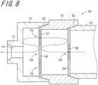
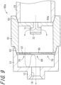
- Fig. 8 is an enlarged cross-sectional view illustrating a silencer 60 included in a gas fire-extinguishing apparatus.
- the silencer 60 has a cylindrical peripheral wall 61, a mounting section 62 which is detachably formed on the branch pipe 19 at one end in the axial direction of the peripheral wall 61, a mounting section 63 detachably formed on the ejection head 13 at the other end in the axial direction of the peripheral wall 61, an end wall 64 formed at one end in the axial direction of the peripheral wall 61 to be perpendicular to the axis of the peripheral wall 61, and an end wall 65 formed at the other end in the axial direction of the peripheral wall 61 to be perpendicular to the axis of the peripheral wall 61.
- At least one of the penetrating holes 66 is formed in the end wall 64 so as to penetrate the end wall 64 in a thickness direction thereof.
- the at least one of the penetrating holes 66 is formed in a center section 68 of the end wall 64, the center of which is on the axis of the peripheral wall 61 and the flow of the fire-extinguishing gas supplied from the branch pipe 19 is throttled.
- a plurality of penetrating holes 67 are formed in the end wall 65 so as to penetrate the end wall 65 in a thickness direction thereof.
- the plurality of penetrating holes 67 are formed in a peripheral section 70 remain except a center section 69 of the end wall 65 and the center of which is on the axis of the peripheral wall 61.
- the end walls 64 and 65 are made of, for example, the punching metal.
- the fire-extinguishing gas ejected at high speed from the penetrating holes 66 formed in the end wall 64 impacts on the center section 69 of the end wall 65 within the silencer 60, the flow speed thereof is attenuated and the gas is ejected from the plurality of penetrating holes 67 formed in the end wall 65 within the space defined by the end wall 65 and the ejection head 13, and then the gas is ejected from the nozzle hole 16 formed in the nozzle section 12 to the outside.
- the silencer 60 expands the fire-extinguishing gas ejected at high speed from the penetrating holes 66 formed in the end wall 64 into the space within the silencer 60, the flow speed thereof is decreased in the penetrating holes 67 formed in the end wall 65 and thereby the occurrence of sound caused by ejection of the fire-extinguishing gas from the nozzle hole 16 can be suppressed.
- the penetrating holes 67 are not formed in the center section 69 of the end wall 65, however, the penetrating holes 67 may be formed in the center section 69 of the end wall 65.
- the amount of the fire-extinguishing gas ejected at high speed rebounding from the penetrating holes 66 is larger and the flow speed is more decreased in a case where the penetrating holes 67 are not formed in the center section 69 of the end wall 65 than those in a case where the penetrating holes 67 are formed in the center section 69 of the end wall 65 so that the silencing effect is high.
- Fig. 9 is an enlarged cross-sectional view illustrating a silencer 60a included in a gas fire-extinguishing apparatus.
- the silencer 60a has a cylindrical peripheral wall 61, a mounting section 62 which is detachably formed on the branch pipe 19 at one end in the axial direction of the peripheral wall 61, a mounting section 63 detachably formed on an ejection head 13 at the other end in the axial direction of the peripheral wall 61, an end wall 64a formed at one end in the axial direction of the peripheral wall 61 to be perpendicular to the axis of the peripheral wall 61, and an end wall 65 formed at the other end in the axial direction of the peripheral wall 61 to be perpendicular to the axis of the peripheral wall 61.
- a guide section 72 is formed in the end wall 64a so as to be on the axis of the peripheral wall 61 and face an inner space of the peripheral wall 61, wherein the guide section 72 has a plurality of nozzle holes 71 which eject the high-pressure fire-extinguishing gas supplied from the branch pipe 19 to the inner space defined by the peripheral wall 61 and the end walls 64a and 65.
- the plurality of nozzle holes 71 of the guide section 72 are formed to be spaced at equal angles in the axial direction of the peripheral wall 61 and are on an axis thereof orthogonal to the axis of the peripheral wall 61.
- the plurality of penetrating holes 67 are formed so as to penetrate the end wall 65 in a thickness direction thereof.
- the plurality of penetrating holes 67 are formed in a peripheral section 70 remaining except the center section 69 of the end wall 65, the center of which is on the axis of the peripheral wall 61.
- the end wall 65 is made of, for example, the punching metal.
- the penetrating holes 67 are not formed in the center section 69 of the end wall 65, however, the penetrating holes 67 may be formed in the center section 69 of the end wall 65.
- the fire-extinguishing gas ejected at high speed from the nozzle holes 71 of the guide section 72 formed in the end wall 64a impacts on the inner peripheral surface of the peripheral wall 61 within the silencer 60a, the flow speed thereof is attenuated, and then the gas is ejected from the plurality of penetrating holes 67 formed in the end wall 65 within the space defined by the end wall 65 and the ejection head 13, the gas is ejected from the nozzle hole 16 formed in the nozzle section 12 to the outside.
- the silencer 60a expands the fire-extinguishing gas ejected at high speed from the nozzle holes 71 into the space within the silencer 60, the flow speed thereof is decreased in the penetrating holes 67 formed in the end wall 65 and thereby the occurrence of sound caused by ejection of the fire-extinguishing gas from the nozzle hole 16 can be suppressed.
- Fig. 10 is an enlarged cross-sectional view illustrating a silencer 17d included in a gas fire-extinguishing apparatus.
- the silencer 17d is, for example, attached to an ejection head 13 disposed on a wall surface of the fire-extinguishing area to be suitably used.
- the silencer 17d has a cylindrical peripheral wall 81, an end wall 82 which is formed at one end in the axial direction of the peripheral wall 81 to be perpendicular to the axis of the peripheral wall 81, and a mounting section 83 detachably formed on the ejection head 13.
- the silencer 17d also includes an end wall 84 formed at the other end in the axial direction of the peripheral wall 81 to be perpendicular to the axis of the peripheral wall 81, a barrier 85 formed between the end wall 82 and the end wall 84 to be perpendicular to the axis of the peripheral wall 81, a cylindrical conduction pipe 87 which guides fire-extinguishing gas ejected from the ejection head 13 to a silencing chamber 86 which is an inner space defined by the peripheral wall 81, the end wall 82 and the barrier 85, and a cylindrical vent pipe 89 which guides fire-extinguishing gas within a silencing chamber 88 which is the inner space defined by the peripheral wall 81, the end wall 84 and the barrier 85 to the outside of the silencer 17d.
- the peripheral wall 81, the end wall 82 and the end wall 84 are made of, for example, the sound absorption material.
- a plurality of penetrating holes 851 are formed so as to penetrate the barrier 85 in a thickness direction thereof.
- the barrier 85 is made of, for example, the punching metal.
- the conduction pipe 87 is disposed to penetrate the barrier 85 and protrude into the silencing chamber 86.
- a connection section 871 which is detachably connected to the ejection head 13 is formed at one end in the axial direction of the conduction pipe 87, and an end plate 872 is formed at the other end in the axial direction of the conduction pipe 87.
- a plurality of penetrating holes 874 are in a portion 873 projected to the silencing chamber 86 of the peripheral wall of the conduction pipe 87 so as to penetrate the peripheral wall of the conduction pipe 87 in a thickness direction thereof.
- a portion 873 in which the plurality of penetrating holes 874 of the conduction pipe 87 are formed is made of, for example, the punching metal.
- the vent pipe 89 is disposed penetrating the barrier 85 and the end wall 82, a wire mesh 891 is disposed in an opening of the silencing chamber 88 side, and the fire-extinguishing gas is ejected from a fire-extinguishing gas ejection port 892 which is an opening to the outside.
- the material of the vent pipe 89 is, for example, vinyl chloride.
- the fire-extinguishing gas ejected at high speed from the plurality of penetrating holes 874 formed in the conduction pipe 87 to the silencing chamber 86 is ejected from the plurality of penetrating holes 851 formed in the barrier 85 to the silencing chamber 88.
- the fire-extinguishing gas ejected from the penetrating holes 851 to the silencing chamber 88 is ejected to the outside of the silencer 17d via a vent pipe 89.
- the silencer 17d is configured such that the fire-extinguishing gas ejected at high speed from a plurality of the penetrating holes 874 is expanded in the space within the silencing chamber 86 and in the space within the silencing chamber 88 so that the flow speed thereof is decreased in the vent pipe 89 and the occurrence of sound caused by ejection of the fire-extinguishing gas from the vent pipe 89 can be suppressed.
- Table 1 Hole diameter (mm) Pressure Flow speed (m/s) Example 1 50 1.5 atmosphere 250
- Table 1 is a calculation example of the pressure and the flow speed with respect to Examples 1 and 2 of the gas fire-extinguishing apparatus using the silencer 17d. Examples 1 and 2 are not according to the invention.
- Example 1 a hole diameter of the vent pipe 89 of the silencer 17d is 50 mm whereas in Example 2, a hole diameter of the vent pipe 89 of the silencer 17d is 80 mm.
- the pressure is the pressure of the silencing chamber 86 and the flow speed (m/s) is the flow speed at the fire-extinguishing gas ejection port 892 of the vent pipe 89.
- the flow speed when the fire-extinguishing gas at two atmospheres is ejected in the air at one atmosphere is about 340 m/s, and a large sound occurs.
- the pressure within the silencing chamber 86 is about 1.5 atmospheres, and the flow speed at the fire-extinguishing gas ejection port 892 is about 250 (m/s).
- the pressure within the silencing chamber 86 is about 1.1 atmospheres, and the flow speed at the fire-extinguishing gas ejection port 892 is about 100 (m/s).
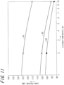
- Fig. 11 is a graph for explaining the silencing effect by the silencer 17d.
- the vertical axis is the sound pressure (dB) and the horizontal axis is the distance (m) from the nozzle section 12.
- the graph 91 is a graph in a case where the silencer is not used
- the graph 92 is a graph in a case of Example 1
- the graph 93 is a graph in a case of Example 2.
- the sound pressure is about 125 dB, however, in Example 1, the sound pressure decreases to about 105 dB and in Example 2, the sound pressure decreases to about 100 dB.
- the sound pressure is about 115 dB, however, in Example 1, the sound pressure decreases to about 96 dB and in Example 2, the sound pressure decreases to about 92 dB.
- the sound pressure can be decreased by about 20dB and in Example 2, the sound pressure can be decreased by about 25 dB compared to the case where the silencer is not used.
- Fig. 12 is an enlarged cross-sectional view illustrating a silencer 17e included in a gas fire-extinguishing apparatus.
- the silencer 17e is attached to, for example, the ejection head 13 disposed on the ceiling of the fire-extinguishing area to be suitably used.
- portions corresponding to the above-described illustration are denoted by the same reference numerals.
- the silencer 17e has the cylindrical peripheral wall 81 the end wall 82 formed at one end in the axial direction of the peripheral wall 81 to be perpendicular to the axis of the peripheral wall 81, and a mounting section 83 detachably formed on the ejection head 13.
- the silencer 17e also includes an end wall 84 formed at the other end in the axial direction of the peripheral wall 81 to be perpendicular to the axis of the peripheral wall 81, the barrier 85 formed between the end wall 82 and the end wall 84 to be perpendicular to the axis of the peripheral wall 81, a cylindrical conduction pipe 87 which guides fire-extinguishing gas ejected from the ejection head 13 to a silencing chamber 86 which is an inner space defined by the peripheral wall 81, the end wall 82 and the barrier 85, and a plurality of cylindrical vent holes 89a which guide the fire-extinguishing gas within a silencing chamber 88 which is the inner space defined by the peripheral wall 81, the end wall 84 and the barrier 85 to the outside of the silencer 17e.
- the peripheral wall 81, the end wall 82 and the end wall 84 are for example, made of the sound absorption material.
- the plurality of penetrating holes 851 are formed so as to penetrate the barrier 85 in a thickness direction thereof.
- the barrier 85 is made of, for example, the punching metal.
- the conduction pipe 87 penetrates the barrier 85 and is disposed to protrude to the silencing chamber 86.
- the connection section 871 which is detachably connected to the ejection head 13 is formed at one end in the axial direction of the conduction pipe 87, and the end plate 872 is formed at the other end in the axial direction of the conduction pipe 87.
- the plurality of penetrating holes 874 are formed in the portion 873 which is projected to the silencing chamber 86 of the peripheral wall of the conduction pipe 87 so as to penetrate the peripheral wall of the conduction pipe 87 in a thickness direction thereof.
- the portion 873 in which the plurality of penetrating holes 874 of the conduction pipe 87 are formed is made of, for example, the punching metal.
- the plurality of vent pipes 89a are disposed to be spaced at equal angles in the peripheral direction with respect to the axis of the peripheral wall 81 and are on an axis orthogonal to the axis of the peripheral wall 81 which is formed so as to penetrate the peripheral wall 81 respectively.
- a fire-extinguishing gas ejection port 892a which is an opening to the outside of the silencer 17e is formed in each vent pipe 89a and the fire-extinguishing gas ejects from each fire-extinguishing gas ejection port 892a to the outside of the silencer 17e.
- the material of the vent pipes 89a for example, is vinyl chloride.
- the fire-extinguishing gas is ejected from the plurality of penetrating holes 851 formed in the barrier 85 to the silencing chamber 88, wherein the fire-extinguishing gas ejected at high speed from the plurality of penetrating holes 874 formed in the conduction pipe 87 to the silencing chamber 86.
- the fire-extinguishing gas ejected from the penetrating holes 851 to the silencing chamber 88 is ejected to the outside of the silencer 17e via the vent pipes 89a.
- the silencer 17e is configured such that the fire-extinguishing gas ejected at high speed from the plurality of penetrating holes 874 is expanded in the space within the silencing chamber 86 and the space within the silencing chamber 88 so that the flow speed in the vent holes 89a is decreased, the occurrence of sound caused by ejection of the fire-extinguishing gas from the vent pipes 89a is suppressed.
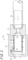
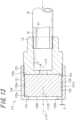
- Fig. 13 is an enlarged cross-sectional view illustrating a silencer 17f included in a gas fire-extinguishing apparatus according to the invention.
- the silencer 17f is, for example, attached to the ejection head 13 disposed on the wall surface of the fire-extinguishing area to be suitably used.
- the silencer 17f has a cylindrical peripheral wall 121, an annular the end wall 122 formed at one end in the axial direction of the peripheral wall 121 to be perpendicular to the axis of the peripheral wall 121, and a mounting section 123 formed at the other end in the axial direction of the peripheral wall 121 and detachably formed on the ejection head 13.
- a silencing chamber 124 is formed in the silencer 17f wherein the silencing chamber 124 is an inner space defined by the ejection head 13, the peripheral wall 121 and the end wall 122.
- a columnar sound absorption material 125 is mounted along the inner peripheral surface of the peripheral wall 121 and accommodated in the silencing chamber 124.
- a casing 129 is constituted by the peripheral wall 121, the end wall 122 and the mounting section 123.
- a inner peripheral surface 121a of the peripheral wall 121 facing the silencing chamber 124 of the casing 129 is cylindrically formed and an inner surface 122a of the end wall 122 facing the silencing chamber 124 is formed on an imaginary plane perpendicular to an axis L121 of the peripheral wall 121.
- a penetrating hole 122b is formed so as to penetrate the end wall 122 in a direction of the axis L121, the center of which is on the axis L121 of the peripheral wall 121.
- the sound absorption material 125 is formed in a columnar shape and an outer peripheral surface 125a of which is formed in a cylindrical shape.
- An end surface 125b of one side of the sound absorption material 125 in a direction of an axis L125 of the sound absorption material 125 and an end surface 125c of the other side are formed on an imaginary plane perpendicular to the axis L125.
- An end surface 12a of the nozzle section 12 of the ejection head 13 on the downstream side of the fire-extinguishing gas ejection direction is formed on an imaginary plane perpendicular to an axis L12 of the nozzle section 12.
- the silencer 17f is charged in the space within the casing 129 from the mounting section 123 in a posture in which the axis L125 of the sound absorption material 125 is aligned or substantially aligned with the axis L121 of the peripheral wall 121.
- the sound absorption material 125 is a right cylindrical shape
- the sound absorption material 125 is detachably configured by screwing an outside screw threaded in the outer peripheral portion of the nozzle section 12 on the downstream side of the fire-extinguishing gas ejection direction to an inside screw threaded in the inner peripheral portion of the mounting section 123.
- the sound absorption material 125 is accommodated in the silencing chamber 124 in a state where one side the end surface 125b and the inner surface 122a of the end wall 122 are surface-contacted with each other and the other side the end surface 125c and the end surface 12a of the nozzle section 12 are surface-contacted with each other.
- the sound absorption material 125 fills the silencing chamber 124 without a gap.
- the hole diameter of the penetrating hole 122b is formed in a size that the fire-extinguishing agent can be effectively ejected.
- the effective hole diameter portion of the penetrating hole 122b may be not only on the end wall surface side but also on the peripheral wall surface side.
- the silencer 17f can be decreased in size.
- the silencer 17f can also be decreased in size by charging the sound absorption material 125 in the space within the casing 129 without a gap.
- the sound absorption material 125 is made of the porous metal in which columnar air gaps are continuous. Since the silencer 125 as described above, is disposed immediately after the nozzle hole 16, the silencer 17f gradually expands the fire-extinguishing gas supplied from the branch pipe 19 with the decreased pressure and the flow speed thereof can be decreased. Accordingly, the occurrence of ejection sound caused by the ejection of the fire-extinguishing gas can be suppressed.
- the fire-extinguishing gas ejected from the nozzle hole 16 can be directly flowed in the porous metal which is the sound absorption material 125 and the fire-extinguishing gas flowed in the porous metal can be directly ejected from the penetrating hole 122b.
- the fire-extinguishing gas ejected from the nozzle hole 16 is directly flowed in the sound absorption material 125, the fire-extinguishing gas is excessively expanded immediately after being ejected from the nozzle hole 16 and the fire-extinguishing gas is flowed in the sound absorption material 125 before a shock wave is generated and thereby the fire-extinguishing gas is decelerated and spreads rapidly. Accordingly, the occurrence of strong turbulence with the shock wave is prevented and noise is suppressed.
- the fire-extinguishing gas is dispersed by the fine air gaps of the sound absorption material 125, the flow speed of the fire-extinguishing gas ejected from the sound absorption material 125 to the outside via penetrating hole 122b is attenuated, and thereby the noise is also suppressed without a large shock wave being generated.
- the silencer 17f is gradually expanded with decreased pressure by the porous metal which is the sound absorption material 125 and the flow speed can be decreased, the occurrence of ejection sound caused by the ejection of the fire-extinguishing gas can be suppressed. Furthermore, since the silencer 17f is configured to suppress rapid expansion of the fire-extinguishing gas with decreased pressure, the occurrence of noise caused by the rapid expansion with decreased pressure can be suppressed.
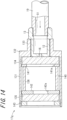
- Fig. 14 is an enlarged cross-sectional view illustrating a silencer 17g included in a gas fire-extinguishing apparatus.
- the silencer 17g is mounted for example, on the ejection head 13 disposed in a wall surface of the fire-extinguishing area.
- the silencer 17g has a cylindrical peripheral wall 131, an end wall 132 formed at the other end in the axial direction of the peripheral wall 131 to be perpendicular to the axis of the peripheral wall 131, and a mounting section 133 continuously formed in the end wall 132 and detachably formed on the ejection head 13.
- An inside screw is threaded in the inner peripheral surface of the peripheral wall 131 at one end in the axial direction.
- a silencing chamber 140 which is an inner space defined by the peripheral wall 131, the end wall 132 and the ejection head 13 is formed in the silencer 17g.
- the silencing chamber 140 accommodates a columnar first sound absorption material 134 disposed at one end in the axial direction of the peripheral wall, a columnar second sound absorption material 135 disposed at the other end in the axial direction of the peripheral wall, a cylindrical third sound absorption material 136 disposed between the first sound absorption material 134 and the second sound absorption material 135, an annular end plate 141 supporting the first sound absorption material 134, an annular spacer 142, and a nut 143.
- the first sound absorption material 134 and the second sound absorption material 135 are made of planar columnar porous metal.
- the first sound absorption material 134 is accommodated as mounting at one end in the axial direction of the peripheral wall 131 along the inner peripheral surface and disposed in contact with one surface facing the silencing chamber 140 of the end wall 132 and one end in the axial direction of the ejection head 13.
- An annular end plate 141 having a penetrating hole 141a is disposed at one end in the axial direction of the first sound absorption material 134.
- the end plate 141 is disposed in contact with the first sound absorption material 134 and regulates the movement of the first sound absorption material 134 to one end thereof in the axial direction.
- the third sound absorption material 136 is disposed at one end in the axial direction of the end plate 141.
- the third sound absorption material 136 is realized by the same member as the sound absorption material 33 of the above-described silencer 17.
- the third sound absorption material 136 may be realized by the porous metal.
- the third sound absorption material 136 is accommodated to be mounted along the inner peripheral surface of the peripheral wall 131.
- An annular spacer 142 having a penetrating hole 142a is disposed at one end in the axial direction of the third sound absorption material 136.
- the spacer 142 is disposed in contact with the second sound absorption material 135 and holds the interval between the third sound absorption material 136 and the second sound absorption material 135.
- the second sound absorption material 135 is disposed at one end in the axial direction of the spacer 142.
- the second sound absorption material 135 may be formed in the same shape as the first sound absorption material 134 and may be formed differently from the first sound absorption material 134.
- the second sound absorption material 135 is accommodated to be mounted along the inner peripheral surface of the peripheral wall 131.
- the nut 143 is disposed at one end in the axial direction of the second sound absorption material 135.
- An outside screw is threaded in the outer peripheral portion of the nut 143 and the nut 143 is fastened in a screwed state to an inside screw threaded in the inner peripheral portion of an opening end side of the peripheral wall 131, and the nut 143 supports the second sound absorption material 135 while pressing it against the other end side in the axial direction thereof. Accordingly, each of the sound absorption materials 134, 135 and 136, the end plate 141 and the spacer 142 are regulated to be displaced to one end side in the axial direction thereof.
- the silencer 17g is disposed as accommodating three sound absorption materials. As described above, since the first sound absorption material 134 is disposed immediately after the nozzle hole 16, the silencer 17g is configured such that the fire-extinguishing gas supplied from the branch pipe 19 side is gradually expanded with decreased pressure and the flow speed thereof can be decreased. In addition, since the third sound absorption material 136 is disposed, the sound vibration caused by the ejection flow of the fire-extinguishing gas is absorbed by the third sound absorption material 136 and thereby the occurrence of ejection sound caused by the ejection of the fire-extinguishing gas can be suppressed.
- the fire-extinguishing gas passing the third sound absorption material 136 can further decrease the pressure and the flow speed thereof can be decreased. Accordingly, the occurrence of ejection sound caused by the ejection of the fire-extinguishing gas can be suppressed.
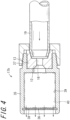
- Fig. 15 is an enlarged cross-sectional view illustrating a silencer 17h included in a gas fire-extinguishing apparatus according to the invention.
- the silencer 17h is mounted, for example, on the branch pipe 19 disposed in a wall surface of the fire-extinguishing area via an ejection head 13.
- the silencer 17h of the embodiment includes the ejection head 13, a bottomed cylindrical casing 150, a nut 151 which is screwed to an opening of the casing 150, a cylindrical first sound absorption material 152 mounted on the ejection head 13, a cylindrical second sound absorption material 153 accommodated in the casing 150 and disposed along the inner peripheral surface of the casing 150, an annular-shaped first supporting piece 154 mounted on a base end section of the ejection head 13 within the casing 150, a disk-shaped second supporting piece 155 disposed in contact with the end surface of the ejection head 13 on the opening side within the casing 150, and a disk-shaped third sound absorption material 156 held in a supported state in the opening of the casing 150 by the nut 151.
- the casing 150 has a right cylindrical section 157, a flange section 158 projecting perpendicularly from one end in the axial direction of the cylindrical section 157 radially and outwardly, and an annular the end wall 159 extending from the other end in the axial direction of the cylindrical section 157 radially and inwardly.
- An outside screw 160 is threaded in an outer peripheral portion of the flange section 158.
- An insertion hole 161 is formed in the end wall 159 in which the base end section of the ejection nozzle 13 is inserted on the center axis thereof.
- the casing 150 as described above, is made of metal.
- the first to the third sound absorption materials 152, 153 and 156 are made of the porous metal as described above.
- the nut 151 has a right cylindrical section 162 and a flange section 163 projecting from one end in the axial direction of the cylindrical section 162 radially and inwardly.
- An inside screw 164 is threaded in the inner peripheral surface of the other end in the axial direction of the cylindrical section 162 and screwed to an outside screw 160 of the casing 150.
- the nut 151 as described above, is made of metal.
- the nut 151 is screwed to the outside screw 160 of the casing 150 so that the peripheral section of the third sound absorption material 156 is pinched by the flange section 158 of the casing 150 and the flange section 163 of the nut 151, and at the same time, the second supporting piece 155 is pinched by the third sound absorption material 156 and the end wall 165 of the ejection head 13, and thereby ejection thereof from the casing 150 of a second sound absorption material 153 is prevented.
- the ejection head 13 has an engaging section 166 in which a fastening tool such as spanner is engaged, a cylindrical section 167 extended to the engaging section 166 in the axial direction thereof, and the end wall 165 which closes one end in the axial direction of the cylindrical section 167.
- the nozzle holes 16 are formed in the cylindrical section 157 so as to penetrate in a thickness direction thereof at intervals of, for example, every 90° in a peripheral direction thereof.
- An outside screw 168 is threaded in the base section near the engaging section 166 of the cylindrical section 167.
- the high-pressure fire-extinguishing gas supplied from the branch pipe 19 to the ejection head 13 is ejected from each the nozzle hole 16 of the ejection head 13 within the first sound absorption material 152, and the shock wave thereof is rapidly dispersed and decelerated, so that the occurrence of strong turbulence with the shock wave is prevented and the sound can be decreased.
- the fire-extinguishing gas ejected from the first sound absorption material 152 to the space 170 enters the second sound absorption material 153 and thereby the gas rapidly dispersed and decelerated similar to the first sound absorption material 152, and is reflected by the inner peripheral surface of the casing 150 and directed to the third sound absorption material 156.
- the fire-extinguishing gas having entered the third sound absorption material 156 is dispersed and decelerated before being rapidly expanded similar to the above-described first and second sound absorption materials 152 and 153, so that the sound is further decreased and ejection sound caused by the ejection of the fire-extinguishing gas can be particularly decreased.
- the plurality of ejection nozzles 16 are formed in the cylindrical section 12 of the ejection head 13 to be perpendicular to the axial direction thereof and thereby the fire-extinguishing gas is ejected radially and outwardly, however, in yet another embodiment of the invention, the nozzle holes 16 inclined to the opening of the casing 150 may be formed in the cylindrical section of the ejection head 13 and thereby the gas passing the first sound absorption material 152 may be ejected to the third sound absorption material 156 as it is. Even such constitution can obtain the same advantage.
Landscapes
- Health & Medical Sciences (AREA)
- Public Health (AREA)
- Business, Economics & Management (AREA)
- Emergency Management (AREA)
- Fire-Extinguishing By Fire Departments, And Fire-Extinguishing Equipment And Control Thereof (AREA)
- Nozzles (AREA)
Claims (3)
- Gasfeuerlöschvorrichtung, umfassend:einen Ausstoßkopf 13 mit einem Düsenabschnitt 12, der Hochdruck-Feuerlöschgas in einen Raum ausstößt;ein Leitungsrohr 14, das mit dem Ausstoßkopf 13 verbunden ist und Hochdruck-Feuerlöschgas zum Ausstoßkopf 13 leitet;eine Feuerlöschgaszufuhrquelle, die das Hochdruck-Feuerlöschgas dem Leitungsrohr 14 zuführt; undeinen Schalldämpfer 17f, der am Ausstoßkopf 13 angeordnet ist und Schall dämpft, der durch das Ausstoßen des Feuerlöschgases aus dem Düsenabschnitt 12 verursacht wird,wobei der Schalldämpfer 17f Folgendes umfasst:ein Gehäuse 129, umfassend eine zylindrische Umfangswand 121, eine ringförmige Endwand 122, die an einem Ende in einer axialen Richtung der Umfangswand 121 ausgebildet ist, um senkrecht zu einer Achse der Umfangswand 121 zu sein, und einen Montageabschnitt 123, der lösbar an dem Ausstoßkopf 13 montiert ist; undein Schallabsorptionsmaterial 125, das in einem von der Umfangswand 121, der Endwand 122 und dem Ausstoßkopf 13 definierten Innenraum untergebracht ist und aus einem porösen Metall besteht,wobei:das Schallabsorptionsmaterial 125 in einer Säulenform ausgebildet ist und eine Außenumfangsfläche davon in einer Zylinderform ausgebildet ist,ein innerer Umfangsabschnitt des Montageabschnitts 123 ein Schraubengewinde einschließt und ein äußerer Umfangsabschnitt des Düsenabschnitts 12 ein entsprechendes Schraubengewinde einschließt,eine Endfläche einer Seite 125b des Schallabsorptionsmaterials 125 in einer Richtung einer Achse des Schallabsorptionsmaterials 125 und eine Endfläche 125c der anderen Seite auf imaginären Ebenen senkrecht zu der Achse des Schallabsorptionsmaterials ausgebildet sind,die Endfläche 125b einer Seite und die Endwand 122 miteinander in Oberflächenkontakt stehen;und die Endfläche 125c der anderen Seite und die Endfläche des Düsenabschnitts 12 durch Verschrauben des Schraubengewindes im äußeren Umfangsabschnitt des Düsenabschnitts 12 mit dem Schraubengewinde im inneren Umfangsabschnitt des Befestigungsabschnitts 123 miteinander in Oberflächenkontakt stehen.
- Gasfeuerlöschvorrichtung nach Anspruch 1, wobei das Schallabsorptionsmaterial 125 ein erstes Schallabsorptionsmaterial 134, das an einem Ende in der axialen Richtung der Umfangswand 121 angeordnet ist, und ein zweites Schallabsorptionsmaterial 135, das an dem anderen Ende in der axialen Richtung der Umfangswand 121 angeordnet ist, umfasst.
- Gasfeuerlöschvorrichtung nach Anspruch 2, wobei der Schalldämpfer 17f ferner ein drittes Schallabsorptionsmaterial 136 umfasst, das zwischen dem ersten Schallabsorptionsmaterial 134 und dem zweiten Schallabsorptionsmaterial 135 angeordnet ist.
Applications Claiming Priority (6)
| Application Number | Priority Date | Filing Date | Title |
|---|---|---|---|
| JP2009244986 | 2009-10-23 | ||
| JP2010023575 | 2010-02-04 | ||
| JP2010086586 | 2010-04-02 | ||
| JP2010161096A JP5276630B2 (ja) | 2009-10-23 | 2010-07-15 | ガス消火設備 |
| PCT/JP2010/068087 WO2011049002A1 (ja) | 2009-10-23 | 2010-10-14 | ガス消火設備 |
| EP10824851.9A EP2491984B1 (de) | 2009-10-23 | 2010-10-14 | Anlage für feuerlöschendes gas |
Related Parent Applications (2)
| Application Number | Title | Priority Date | Filing Date |
|---|---|---|---|
| EP10824851.9A Division EP2491984B1 (de) | 2009-10-23 | 2010-10-14 | Anlage für feuerlöschendes gas |
| EP10824851.9A Division-Into EP2491984B1 (de) | 2009-10-23 | 2010-10-14 | Anlage für feuerlöschendes gas |
Publications (4)
| Publication Number | Publication Date |
|---|---|
| EP3243552A2 EP3243552A2 (de) | 2017-11-15 |
| EP3243552A3 EP3243552A3 (de) | 2018-02-21 |
| EP3243552B1 true EP3243552B1 (de) | 2024-03-06 |
| EP3243552C0 EP3243552C0 (de) | 2024-03-06 |
Family
ID=43900229
Family Applications (2)
| Application Number | Title | Priority Date | Filing Date |
|---|---|---|---|
| EP17178419.2A Active EP3243552B1 (de) | 2009-10-23 | 2010-10-14 | Anlage für feuerlöschendes gas |
| EP10824851.9A Active EP2491984B1 (de) | 2009-10-23 | 2010-10-14 | Anlage für feuerlöschendes gas |
Family Applications After (1)
| Application Number | Title | Priority Date | Filing Date |
|---|---|---|---|
| EP10824851.9A Active EP2491984B1 (de) | 2009-10-23 | 2010-10-14 | Anlage für feuerlöschendes gas |
Country Status (6)
| Country | Link |
|---|---|
| US (1) | US9457214B2 (de) |
| EP (2) | EP3243552B1 (de) |
| JP (1) | JP5276630B2 (de) |
| KR (2) | KR101352714B1 (de) |
| CN (3) | CN106139480A (de) |
| WO (1) | WO2011049002A1 (de) |
Families Citing this family (31)
| Publication number | Priority date | Publication date | Assignee | Title |
|---|---|---|---|---|
| JP5276630B2 (ja) | 2009-10-23 | 2013-08-28 | エア・ウォーター防災株式会社 | ガス消火設備 |
| JP4988945B2 (ja) * | 2009-10-23 | 2012-08-01 | エア・ウォーター防災株式会社 | ガス消火設備 |
| JP5972518B2 (ja) * | 2009-11-02 | 2016-08-17 | 株式会社コーアツ | ガス系消火設備用の消音機能を有する噴射ヘッド |
| JP2011120797A (ja) * | 2009-12-11 | 2011-06-23 | Air Water Safety Service Inc | 消火ガス噴射装置 |
| US8887820B2 (en) * | 2011-05-12 | 2014-11-18 | Fike Corporation | Inert gas suppression system nozzle |
| JP5276728B1 (ja) * | 2012-02-21 | 2013-08-28 | 株式会社コーアツ | ガス系消火設備用の消音機能を有する噴射ヘッド |
| TWI566804B (zh) * | 2012-02-21 | 2017-01-21 | 高壓股份有限公司 | 氣體系滅火設備用的具有消音功能的噴射頭 |
| JP5276730B1 (ja) * | 2012-03-21 | 2013-08-28 | 株式会社コーアツ | ガス系消火設備用の消音機能を有する噴射ヘッド |
| US9597537B2 (en) | 2012-05-03 | 2017-03-21 | Koatsu Co., Ltd. | Injection head having silencing function for gas type fire extinguisher |
| JP5989591B2 (ja) * | 2013-04-17 | 2016-09-07 | 株式会社コーアツ | ガス系消火設備用の消音機能を有する噴射ヘッド |
| JP6305688B2 (ja) * | 2013-04-17 | 2018-04-04 | 株式会社コーアツ | ガス系消火設備用の消音機能を有する噴射ヘッド |
| JP6196955B2 (ja) * | 2013-10-02 | 2017-09-13 | エア・ウォーター防災株式会社 | 消火ガス噴射装置およびそれを備えたガス消火装置 |
| KR102108374B1 (ko) | 2013-10-25 | 2020-05-08 | 삼성전자주식회사 | 스토리지 시스템 및 그것의 비신호 분석 방법 |
| GB2543357A (en) * | 2015-10-16 | 2017-04-19 | Graviner Ltd Kidde | Fire supression systems |
| WO2017096261A1 (en) | 2015-12-04 | 2017-06-08 | Tyco Fire Products Lp | Low pressure drop acoustic suppressor nozzle for inert gas discharge system |
| CN208694106U (zh) | 2015-12-04 | 2019-04-05 | 泰科消防产品有限合伙公司 | 一种喷嘴、喷嘴组件以及灭火喷嘴组件 |
| CN105641841A (zh) * | 2016-01-25 | 2016-06-08 | 维梯埃消防设备(上海)有限公司 | 一种消音装置 |
| RU2717772C1 (ru) * | 2016-06-13 | 2020-03-25 | Коацу Ко., Лтд. | Огнетушитель |
| CN106247037A (zh) * | 2016-08-25 | 2016-12-21 | 吴速 | 一种灭火介质输送带及其快速放带盘 |
| KR102620362B1 (ko) * | 2016-08-31 | 2024-01-04 | 삼성전자주식회사 | 공기조화기 |
| JP6779735B2 (ja) * | 2016-10-07 | 2020-11-04 | ニッタン株式会社 | ガス消火設備用ガス放出ノズル |
| EP3311886A1 (de) * | 2016-10-20 | 2018-04-25 | Siemens Schweiz AG | Schallgedämpfte löschdüsenanordnung mit frequenzselektiver schalldämpfschicht sowie geeignete verwendung |
| KR102556716B1 (ko) | 2016-12-26 | 2023-07-18 | 가부시키가이샤 고아츠 | 가스계 소화 설비용 소음 기능을 갖는 분사 헤드 및 그 보관·조립 방법 |
| MY205180A (en) * | 2017-05-19 | 2024-10-04 | Koatsu Co Ltd | Injection head for liquefied fire-extinguishing agent |
| US11117007B2 (en) * | 2017-11-10 | 2021-09-14 | Carrier Corporation | Noise reducing fire suppression nozzles |
| TWI799647B (zh) * | 2018-10-02 | 2023-04-21 | 日商高壓股份有限公司 | 液態滅火劑用噴射頭 |
| CN114599430A (zh) * | 2019-08-09 | 2022-06-07 | 泰科消防产品有限合伙公司 | 灭火喷嘴和系统 |
| US12186606B2 (en) * | 2020-01-31 | 2025-01-07 | Kidde-Fenwal, Llc | Low noise discharge nozzle |
| US20210291000A1 (en) * | 2020-03-20 | 2021-09-23 | Kidde Technologies, Inc. | Fire suppression systems and methods of controlling flow of fire suppressant agents in fire suppression systems |
| CN113209528B (zh) * | 2021-06-15 | 2025-05-27 | 浙江理工大学 | 引射式超声速干粉灭火装置 |
| CN115750291A (zh) * | 2022-10-26 | 2023-03-07 | 中国大唐集团科学技术研究总院有限公司 | 一种压缩空气储能排气系统 |
Family Cites Families (62)
| Publication number | Priority date | Publication date | Assignee | Title |
|---|---|---|---|---|
| US1811762A (en) * | 1929-05-08 | 1931-06-23 | Burgess Lab Inc C F | Exhaust muffler |
| US1844104A (en) | 1929-05-08 | 1932-02-09 | Burgess Lab Inc C F | Exhaust muffler |
| US1844106A (en) | 1929-05-08 | 1932-02-09 | Burgess Lab Inc C F | Exhaust muffler |
| US1844105A (en) * | 1929-05-08 | 1932-02-09 | Burgess Lab Inc C F | Exhaust muffler |
| US2030017A (en) | 1930-09-26 | 1936-02-04 | Mile Raymond | Automatic smoke preventer |
| US1968456A (en) | 1932-07-28 | 1934-07-31 | Burgess Lab Inc C F | Gaseous pressure wave absorbing construction |
| US2376933A (en) | 1943-01-04 | 1945-05-29 | Stone Wheel Inc | Spark and flame arrestor |
| US2442773A (en) | 1944-05-05 | 1948-06-08 | Bell Telephone Labor Inc | Sound suppressor |
| US2559408A (en) * | 1946-10-11 | 1951-07-03 | Pyrene Mfg Co | Fire extinguisher nozzle for vehicles |
| US2600236A (en) * | 1948-11-16 | 1952-06-10 | Esther Larsen | Muffler with a plurality of passages |
| US2792760A (en) * | 1954-03-26 | 1957-05-21 | Hammer Alexander | Combination flash eliminator and stabilizer for a firearm |
| US3339668A (en) | 1965-03-18 | 1967-09-05 | C W Morris Company | Air exhaust noise attenuator |
| US3672465A (en) * | 1970-10-15 | 1972-06-27 | Blatt Leland F | Gas exhaust silencer |
| US3960239A (en) * | 1973-08-15 | 1976-06-01 | Barry Wright Corporation | Noise-reducing fluid-flow devices |
| JPS515799U (de) | 1974-06-29 | 1976-01-16 | ||
| US3949828A (en) | 1974-08-30 | 1976-04-13 | Barry Wright Corporation | Fluid exhaust silencer |
| JPS5512824Y2 (de) * | 1975-08-05 | 1980-03-22 | ||
| JPS6033544B2 (ja) | 1977-03-17 | 1985-08-03 | 株式会社豊田中央研究所 | 低騒音用圧力流体放出装置 |
| JPS5644423Y2 (de) | 1978-07-12 | 1981-10-17 | ||
| JPS56161110U (de) * | 1980-04-30 | 1981-12-01 | ||
| JPS58103100U (ja) | 1982-01-06 | 1983-07-13 | 横河電機株式会社 | 空気パ−ジ用消音器 |
| JPS5933450U (ja) | 1982-08-25 | 1984-03-01 | ニツタン株式会社 | ガス系消火設備の試験用ガス排出管の消音器 |
| JPS60175718A (ja) * | 1984-02-22 | 1985-09-09 | Nippon Soken Inc | 内燃機関用消音器 |
| JPH0332736Y2 (de) * | 1985-03-22 | 1991-07-11 | ||
| JPH0640896Y2 (ja) * | 1987-11-13 | 1994-10-26 | 日酸運輸株式会社 | サイレンサー |
| SU1657679A1 (ru) | 1989-02-28 | 1991-06-23 | Московский автомеханический институт | Глушитель шума газовой струи |
| US5250094A (en) * | 1992-03-16 | 1993-10-05 | Donaldson Company, Inc. | Ceramic filter construction and method |
| JP3093440B2 (ja) | 1992-05-26 | 2000-10-03 | 日本電気株式会社 | 光磁気記録媒体及びその製造方法 |
| JPH0742849B2 (ja) | 1992-06-30 | 1995-05-15 | 三和産業株式会社 | コンクリートモルタル吹付機の排気用消音装置 |
| JPH0647683A (ja) | 1992-07-08 | 1994-02-22 | Shuichi Teramoto | ホースベルトの離脱装置およびホースの離脱装置 |
| JP2593556Y2 (ja) * | 1993-01-29 | 1999-04-12 | 株式会社クボタ | 空気圧ノズル |
| US5511621A (en) * | 1994-04-08 | 1996-04-30 | Factory Mutual Research | Local flooding fine water spray fire suppression system using recirculation principles |
| JPH08173565A (ja) | 1994-12-22 | 1996-07-09 | Koatsu:Kk | 不活性ガス消火設備における消火方法及びその設備 |
| US5799652A (en) | 1995-05-22 | 1998-09-01 | Hypoxico Inc. | Hypoxic room system and equipment for Hypoxic training and therapy at standard atmospheric pressure |
| US6314754B1 (en) | 2000-04-17 | 2001-11-13 | Igor K. Kotliar | Hypoxic fire prevention and fire suppression systems for computer rooms and other human occupied facilities |
| JPH09124302A (ja) | 1995-10-30 | 1997-05-13 | Masayuki Imai | 酸素濃縮器 |
| JPH09324617A (ja) * | 1996-06-04 | 1997-12-16 | Ndc Co Ltd | 消音器 |
| JP3037617B2 (ja) * | 1996-07-15 | 2000-04-24 | シーケーディ株式会社 | 消音器及びその製造方法 |
| DE19719535A1 (de) | 1996-10-16 | 1998-04-23 | Gerd Schwertfeger | Vorrichtung zur Schalldämpfung |
| JPH1190285A (ja) * | 1997-09-17 | 1999-04-06 | Kenki Engineering:Kk | 局部塗装方法および装置 |
| JPH11325655A (ja) | 1998-05-14 | 1999-11-26 | Matsushita Seiko Co Ltd | 消音器および空気調和機 |
| US6112850A (en) * | 1999-09-07 | 2000-09-05 | Met Pro Corporation | Acoustic silencer nozzle |
| CN2406694Y (zh) | 2000-02-29 | 2000-11-22 | 丁一 | 气体灭火喷嘴 |
| AU2001277654B2 (en) * | 2000-04-17 | 2006-09-07 | Igor K. Kotliar | Hypoxic fire prevention and fire suppression systems and breathable fire extinguishing compositions |
| IT1317475B1 (it) | 2000-05-05 | 2003-07-09 | Vesta S R L | Ugello silenziato per la scarica di gas estinguenti. |
| DE60216244T2 (de) * | 2001-03-29 | 2007-05-10 | Kidde IP Holdings Ltd., Colnbrook, Slough | Mittel zum feuerlöschen und zur explosionsunterdrückung |
| DE20120671U1 (de) * | 2001-12-21 | 2002-03-14 | TOTAL WALTHER GmbH, Feuerschutz und Sicherheit, 51069 Köln | Feuerlöschanlage |
| JP2003206718A (ja) * | 2002-01-16 | 2003-07-25 | Fuji Heavy Ind Ltd | 消音器 |
| JP4196181B2 (ja) | 2003-04-25 | 2008-12-17 | 英雄 中嶋 | 吸音材料 |
| JP2005002873A (ja) | 2003-06-11 | 2005-01-06 | Aisin Seiki Co Ltd | 消音器 |
| EP1684891A1 (de) * | 2003-11-20 | 2006-08-02 | Air Institution, Inc. | Abgasfilter und -filtersystem |
| JP4561349B2 (ja) | 2004-12-20 | 2010-10-13 | パナソニック電工株式会社 | 液体ノズル |
| JP4613619B2 (ja) | 2005-01-13 | 2011-01-19 | Smc株式会社 | サイレンサ |
| JP2006296491A (ja) | 2005-04-15 | 2006-11-02 | Air Water Safety Service Inc | 液体噴射用発泡ノズル |
| JP2006307719A (ja) | 2005-04-27 | 2006-11-09 | Calsonic Kansei Corp | 車両用消音器 |
| US7587969B2 (en) * | 2005-08-26 | 2009-09-15 | Robert Silvers | Asymmetric firearm silencer with coaxial elements |
| KR100655293B1 (ko) * | 2005-11-23 | 2006-12-08 | 대우조선해양 주식회사 | 장거리 기류이송용 축류식 터보 제트팬 |
| JP4917803B2 (ja) * | 2005-12-26 | 2012-04-18 | 株式会社ガスター | 微細気泡噴出ノズル及びそれを利用した微細気泡発生装置 |
| JP4969300B2 (ja) * | 2006-05-18 | 2012-07-04 | 英夫 吉田 | 消火ガス噴射器 |
| KR100755722B1 (ko) | 2007-03-08 | 2007-09-05 | 한국뉴매틱(주) | 공압장치용 사일렌서 |
| CN101366997B (zh) | 2008-06-30 | 2011-07-20 | 芜湖世纪凯旋消防设备有限公司 | 一种气体灭火系统的灭火剂喷头 |
| JP5276630B2 (ja) | 2009-10-23 | 2013-08-28 | エア・ウォーター防災株式会社 | ガス消火設備 |
-
2010
- 2010-07-15 JP JP2010161096A patent/JP5276630B2/ja active Active
- 2010-10-14 EP EP17178419.2A patent/EP3243552B1/de active Active
- 2010-10-14 EP EP10824851.9A patent/EP2491984B1/de active Active
- 2010-10-14 WO PCT/JP2010/068087 patent/WO2011049002A1/ja not_active Ceased
- 2010-10-14 US US13/503,441 patent/US9457214B2/en active Active
- 2010-10-14 CN CN201610528048.9A patent/CN106139480A/zh active Pending
- 2010-10-14 CN CN201080047808.5A patent/CN102573998B/zh active Active
- 2010-10-14 KR KR1020127013224A patent/KR101352714B1/ko active Active
- 2010-10-14 KR KR1020137023062A patent/KR101412253B1/ko active Active
- 2010-10-14 CN CN201410226960.XA patent/CN104014097B/zh active Active
Also Published As
| Publication number | Publication date |
|---|---|
| CN102573998A (zh) | 2012-07-11 |
| EP3243552C0 (de) | 2024-03-06 |
| CN104014097A (zh) | 2014-09-03 |
| JP5276630B2 (ja) | 2013-08-28 |
| KR20120093305A (ko) | 2012-08-22 |
| JP2011255152A (ja) | 2011-12-22 |
| KR20130112952A (ko) | 2013-10-14 |
| US9457214B2 (en) | 2016-10-04 |
| EP2491984B1 (de) | 2020-02-19 |
| US20120205128A1 (en) | 2012-08-16 |
| EP3243552A2 (de) | 2017-11-15 |
| EP2491984A1 (de) | 2012-08-29 |
| EP2491984A4 (de) | 2015-10-07 |
| KR101352714B1 (ko) | 2014-01-16 |
| EP3243552A3 (de) | 2018-02-21 |
| CN102573998B (zh) | 2014-12-03 |
| CN106139480A (zh) | 2016-11-23 |
| WO2011049002A1 (ja) | 2011-04-28 |
| KR101412253B1 (ko) | 2014-06-25 |
| CN104014097B (zh) | 2017-12-19 |
Similar Documents
| Publication | Publication Date | Title |
|---|---|---|
| EP3243552B1 (de) | Anlage für feuerlöschendes gas | |
| JP7591009B2 (ja) | ガス消火設備 | |
| HK1229746A (en) | Equipment room in building, gas fire-extinguishing method and gas fire-extinguishing equipment, and muffler | |
| HK1229746A1 (en) | Equipment room in building, gas fire-extinguishing method and gas fire-extinguishing equipment, and muffler |
Legal Events
| Date | Code | Title | Description |
|---|---|---|---|
| PUAI | Public reference made under article 153(3) epc to a published international application that has entered the european phase |
Free format text: ORIGINAL CODE: 0009012 |
|
| STAA | Information on the status of an ep patent application or granted ep patent |
Free format text: STATUS: THE APPLICATION HAS BEEN PUBLISHED |
|
| AC | Divisional application: reference to earlier application |
Ref document number: 2491984 Country of ref document: EP Kind code of ref document: P |
|
| AK | Designated contracting states |
Kind code of ref document: A2 Designated state(s): AL AT BE BG CH CY CZ DE DK EE ES FI FR GB GR HR HU IE IS IT LI LT LU LV MC MK MT NL NO PL PT RO RS SE SI SK SM TR |
|
| PUAL | Search report despatched |
Free format text: ORIGINAL CODE: 0009013 |
|
| AK | Designated contracting states |
Kind code of ref document: A3 Designated state(s): AL AT BE BG CH CY CZ DE DK EE ES FI FR GB GR HR HU IE IS IT LI LT LU LV MC MK MT NL NO PL PT RO RS SE SI SK SM TR |
|
| RIC1 | Information provided on ipc code assigned before grant |
Ipc: A62C 31/02 20060101AFI20180115BHEP |
|
| STAA | Information on the status of an ep patent application or granted ep patent |
Free format text: STATUS: REQUEST FOR EXAMINATION WAS MADE |
|
| 17P | Request for examination filed |
Effective date: 20180817 |
|
| RBV | Designated contracting states (corrected) |
Designated state(s): AL AT BE BG CH CY CZ DE DK EE ES FI FR GB GR HR HU IE IS IT LI LT LU LV MC MK MT NL NO PL PT RO RS SE SI SK SM TR |
|
| STAA | Information on the status of an ep patent application or granted ep patent |
Free format text: STATUS: EXAMINATION IS IN PROGRESS |
|
| 17Q | First examination report despatched |
Effective date: 20191129 |
|
| GRAP | Despatch of communication of intention to grant a patent |
Free format text: ORIGINAL CODE: EPIDOSNIGR1 |
|
| STAA | Information on the status of an ep patent application or granted ep patent |
Free format text: STATUS: GRANT OF PATENT IS INTENDED |
|
| INTG | Intention to grant announced |
Effective date: 20230921 |
|
| GRAS | Grant fee paid |
Free format text: ORIGINAL CODE: EPIDOSNIGR3 |
|
| GRAA | (expected) grant |
Free format text: ORIGINAL CODE: 0009210 |
|
| STAA | Information on the status of an ep patent application or granted ep patent |
Free format text: STATUS: THE PATENT HAS BEEN GRANTED |
|
| AC | Divisional application: reference to earlier application |
Ref document number: 2491984 Country of ref document: EP Kind code of ref document: P |
|
| AK | Designated contracting states |
Kind code of ref document: B1 Designated state(s): AL AT BE BG CH CY CZ DE DK EE ES FI FR GB GR HR HU IE IS IT LI LT LU LV MC MK MT NL NO PL PT RO RS SE SI SK SM TR |
|
| REG | Reference to a national code |
Ref country code: GB Ref legal event code: FG4D |
|
| REG | Reference to a national code |
Ref country code: CH Ref legal event code: EP |
|
| REG | Reference to a national code |
Ref country code: DE Ref legal event code: R096 Ref document number: 602010069290 Country of ref document: DE |
|
| REG | Reference to a national code |
Ref country code: IE Ref legal event code: FG4D |
|
| U01 | Request for unitary effect filed |
Effective date: 20240404 |
|
| U07 | Unitary effect registered |
Designated state(s): AT BE BG DE DK EE FI FR IT LT LU LV MT NL PT SE SI Effective date: 20240412 |
|
| PG25 | Lapsed in a contracting state [announced via postgrant information from national office to epo] |
Ref country code: GR Free format text: LAPSE BECAUSE OF FAILURE TO SUBMIT A TRANSLATION OF THE DESCRIPTION OR TO PAY THE FEE WITHIN THE PRESCRIBED TIME-LIMIT Effective date: 20240607 |
|
| PG25 | Lapsed in a contracting state [announced via postgrant information from national office to epo] |
Ref country code: HR Free format text: LAPSE BECAUSE OF FAILURE TO SUBMIT A TRANSLATION OF THE DESCRIPTION OR TO PAY THE FEE WITHIN THE PRESCRIBED TIME-LIMIT Effective date: 20240306 Ref country code: RS Free format text: LAPSE BECAUSE OF FAILURE TO SUBMIT A TRANSLATION OF THE DESCRIPTION OR TO PAY THE FEE WITHIN THE PRESCRIBED TIME-LIMIT Effective date: 20240606 |
|
| PG25 | Lapsed in a contracting state [announced via postgrant information from national office to epo] |
Ref country code: ES Free format text: LAPSE BECAUSE OF FAILURE TO SUBMIT A TRANSLATION OF THE DESCRIPTION OR TO PAY THE FEE WITHIN THE PRESCRIBED TIME-LIMIT Effective date: 20240306 |
|
| PG25 | Lapsed in a contracting state [announced via postgrant information from national office to epo] |
Ref country code: RS Free format text: LAPSE BECAUSE OF FAILURE TO SUBMIT A TRANSLATION OF THE DESCRIPTION OR TO PAY THE FEE WITHIN THE PRESCRIBED TIME-LIMIT Effective date: 20240606 Ref country code: NO Free format text: LAPSE BECAUSE OF FAILURE TO SUBMIT A TRANSLATION OF THE DESCRIPTION OR TO PAY THE FEE WITHIN THE PRESCRIBED TIME-LIMIT Effective date: 20240606 Ref country code: HR Free format text: LAPSE BECAUSE OF FAILURE TO SUBMIT A TRANSLATION OF THE DESCRIPTION OR TO PAY THE FEE WITHIN THE PRESCRIBED TIME-LIMIT Effective date: 20240306 Ref country code: GR Free format text: LAPSE BECAUSE OF FAILURE TO SUBMIT A TRANSLATION OF THE DESCRIPTION OR TO PAY THE FEE WITHIN THE PRESCRIBED TIME-LIMIT Effective date: 20240607 Ref country code: ES Free format text: LAPSE BECAUSE OF FAILURE TO SUBMIT A TRANSLATION OF THE DESCRIPTION OR TO PAY THE FEE WITHIN THE PRESCRIBED TIME-LIMIT Effective date: 20240306 |
|
| PG25 | Lapsed in a contracting state [announced via postgrant information from national office to epo] |
Ref country code: IS Free format text: LAPSE BECAUSE OF FAILURE TO SUBMIT A TRANSLATION OF THE DESCRIPTION OR TO PAY THE FEE WITHIN THE PRESCRIBED TIME-LIMIT Effective date: 20240706 |
|
| PG25 | Lapsed in a contracting state [announced via postgrant information from national office to epo] |
Ref country code: SM Free format text: LAPSE BECAUSE OF FAILURE TO SUBMIT A TRANSLATION OF THE DESCRIPTION OR TO PAY THE FEE WITHIN THE PRESCRIBED TIME-LIMIT Effective date: 20240306 |
|
| PG25 | Lapsed in a contracting state [announced via postgrant information from national office to epo] |
Ref country code: CZ Free format text: LAPSE BECAUSE OF FAILURE TO SUBMIT A TRANSLATION OF THE DESCRIPTION OR TO PAY THE FEE WITHIN THE PRESCRIBED TIME-LIMIT Effective date: 20240306 |
|
| PG25 | Lapsed in a contracting state [announced via postgrant information from national office to epo] |
Ref country code: PL Free format text: LAPSE BECAUSE OF FAILURE TO SUBMIT A TRANSLATION OF THE DESCRIPTION OR TO PAY THE FEE WITHIN THE PRESCRIBED TIME-LIMIT Effective date: 20240306 |
|
| PG25 | Lapsed in a contracting state [announced via postgrant information from national office to epo] |
Ref country code: SK Free format text: LAPSE BECAUSE OF FAILURE TO SUBMIT A TRANSLATION OF THE DESCRIPTION OR TO PAY THE FEE WITHIN THE PRESCRIBED TIME-LIMIT Effective date: 20240306 |
|
| U20 | Renewal fee for the european patent with unitary effect paid |
Year of fee payment: 15 Effective date: 20240920 |
|
| PG25 | Lapsed in a contracting state [announced via postgrant information from national office to epo] |
Ref country code: SM Free format text: LAPSE BECAUSE OF FAILURE TO SUBMIT A TRANSLATION OF THE DESCRIPTION OR TO PAY THE FEE WITHIN THE PRESCRIBED TIME-LIMIT Effective date: 20240306 Ref country code: SK Free format text: LAPSE BECAUSE OF FAILURE TO SUBMIT A TRANSLATION OF THE DESCRIPTION OR TO PAY THE FEE WITHIN THE PRESCRIBED TIME-LIMIT Effective date: 20240306 Ref country code: RO Free format text: LAPSE BECAUSE OF FAILURE TO SUBMIT A TRANSLATION OF THE DESCRIPTION OR TO PAY THE FEE WITHIN THE PRESCRIBED TIME-LIMIT Effective date: 20240306 Ref country code: PL Free format text: LAPSE BECAUSE OF FAILURE TO SUBMIT A TRANSLATION OF THE DESCRIPTION OR TO PAY THE FEE WITHIN THE PRESCRIBED TIME-LIMIT Effective date: 20240306 Ref country code: IS Free format text: LAPSE BECAUSE OF FAILURE TO SUBMIT A TRANSLATION OF THE DESCRIPTION OR TO PAY THE FEE WITHIN THE PRESCRIBED TIME-LIMIT Effective date: 20240706 Ref country code: CZ Free format text: LAPSE BECAUSE OF FAILURE TO SUBMIT A TRANSLATION OF THE DESCRIPTION OR TO PAY THE FEE WITHIN THE PRESCRIBED TIME-LIMIT Effective date: 20240306 |
|
| REG | Reference to a national code |
Ref country code: DE Ref legal event code: R097 Ref document number: 602010069290 Country of ref document: DE |
|
| PLBE | No opposition filed within time limit |
Free format text: ORIGINAL CODE: 0009261 |
|
| STAA | Information on the status of an ep patent application or granted ep patent |
Free format text: STATUS: NO OPPOSITION FILED WITHIN TIME LIMIT |
|
| 26N | No opposition filed |
Effective date: 20241209 |
|
| REG | Reference to a national code |
Ref country code: CH Ref legal event code: PL |
|
| GBPC | Gb: european patent ceased through non-payment of renewal fee |
Effective date: 20241014 |
|
| PG25 | Lapsed in a contracting state [announced via postgrant information from national office to epo] |
Ref country code: MC Free format text: LAPSE BECAUSE OF FAILURE TO SUBMIT A TRANSLATION OF THE DESCRIPTION OR TO PAY THE FEE WITHIN THE PRESCRIBED TIME-LIMIT Effective date: 20240306 |
|
| PG25 | Lapsed in a contracting state [announced via postgrant information from national office to epo] |
Ref country code: GB Free format text: LAPSE BECAUSE OF NON-PAYMENT OF DUE FEES Effective date: 20241014 |
|
| PG25 | Lapsed in a contracting state [announced via postgrant information from national office to epo] |
Ref country code: CH Free format text: LAPSE BECAUSE OF NON-PAYMENT OF DUE FEES Effective date: 20241031 |
|
| PG25 | Lapsed in a contracting state [announced via postgrant information from national office to epo] |
Ref country code: IE Free format text: LAPSE BECAUSE OF NON-PAYMENT OF DUE FEES Effective date: 20241014 |
|
| U20 | Renewal fee for the european patent with unitary effect paid |
Year of fee payment: 16 Effective date: 20250922 |
|
| PG25 | Lapsed in a contracting state [announced via postgrant information from national office to epo] |
Ref country code: CY Free format text: LAPSE BECAUSE OF FAILURE TO SUBMIT A TRANSLATION OF THE DESCRIPTION OR TO PAY THE FEE WITHIN THE PRESCRIBED TIME-LIMIT; INVALID AB INITIO Effective date: 20101014 |
|
| PG25 | Lapsed in a contracting state [announced via postgrant information from national office to epo] |
Ref country code: HU Free format text: LAPSE BECAUSE OF FAILURE TO SUBMIT A TRANSLATION OF THE DESCRIPTION OR TO PAY THE FEE WITHIN THE PRESCRIBED TIME-LIMIT; INVALID AB INITIO Effective date: 20101014 |