EP3240180B1 - Motor and electronic apparatus including motor - Google Patents
Motor and electronic apparatus including motor Download PDFInfo
- Publication number
- EP3240180B1 EP3240180B1 EP17168104.2A EP17168104A EP3240180B1 EP 3240180 B1 EP3240180 B1 EP 3240180B1 EP 17168104 A EP17168104 A EP 17168104A EP 3240180 B1 EP3240180 B1 EP 3240180B1
- Authority
- EP
- European Patent Office
- Prior art keywords
- vibrator
- pressing
- motor according
- rolling
- members
- Prior art date
- Legal status (The legal status is an assumption and is not a legal conclusion. Google has not performed a legal analysis and makes no representation as to the accuracy of the status listed.)
- Active
Links
- 230000005540 biological transmission Effects 0.000 claims description 23
- 230000008878 coupling Effects 0.000 claims description 21
- 238000010168 coupling process Methods 0.000 claims description 21
- 238000005859 coupling reaction Methods 0.000 claims description 21
- 238000005096 rolling process Methods 0.000 claims description 16
- CNQCVBJFEGMYDW-UHFFFAOYSA-N lawrencium atom Chemical compound [Lr] CNQCVBJFEGMYDW-UHFFFAOYSA-N 0.000 description 6
- 230000003287 optical effect Effects 0.000 description 6
- 239000000853 adhesive Substances 0.000 description 3
- 230000001070 adhesive effect Effects 0.000 description 3
- 230000001133 acceleration Effects 0.000 description 1
- 238000006073 displacement reaction Methods 0.000 description 1
- 230000000694 effects Effects 0.000 description 1
- 238000003466 welding Methods 0.000 description 1
Images

Classifications
-
- G—PHYSICS
- G02—OPTICS
- G02B—OPTICAL ELEMENTS, SYSTEMS OR APPARATUS
- G02B7/00—Mountings, adjusting means, or light-tight connections, for optical elements
- G02B7/003—Alignment of optical elements
- G02B7/005—Motorised alignment
-
- G—PHYSICS
- G02—OPTICS
- G02B—OPTICAL ELEMENTS, SYSTEMS OR APPARATUS
- G02B7/00—Mountings, adjusting means, or light-tight connections, for optical elements
- G02B7/02—Mountings, adjusting means, or light-tight connections, for optical elements for lenses
- G02B7/023—Mountings, adjusting means, or light-tight connections, for optical elements for lenses permitting adjustment
-
- H—ELECTRICITY
- H02—GENERATION; CONVERSION OR DISTRIBUTION OF ELECTRIC POWER
- H02N—ELECTRIC MACHINES NOT OTHERWISE PROVIDED FOR
- H02N2/00—Electric machines in general using piezoelectric effect, electrostriction or magnetostriction
- H02N2/0005—Electric machines in general using piezoelectric effect, electrostriction or magnetostriction producing non-specific motion; Details common to machines covered by H02N2/02 - H02N2/16
- H02N2/005—Mechanical details, e.g. housings
- H02N2/0055—Supports for driving or driven bodies; Means for pressing driving body against driven body
- H02N2/006—Elastic elements, e.g. springs
-
- H—ELECTRICITY
- H02—GENERATION; CONVERSION OR DISTRIBUTION OF ELECTRIC POWER
- H02N—ELECTRIC MACHINES NOT OTHERWISE PROVIDED FOR
- H02N2/00—Electric machines in general using piezoelectric effect, electrostriction or magnetostriction
- H02N2/02—Electric machines in general using piezoelectric effect, electrostriction or magnetostriction producing linear motion, e.g. actuators; Linear positioners ; Linear motors
- H02N2/026—Electric machines in general using piezoelectric effect, electrostriction or magnetostriction producing linear motion, e.g. actuators; Linear positioners ; Linear motors by pressing one or more vibrators against the driven body
-
- H—ELECTRICITY
- H02—GENERATION; CONVERSION OR DISTRIBUTION OF ELECTRIC POWER
- H02N—ELECTRIC MACHINES NOT OTHERWISE PROVIDED FOR
- H02N2/00—Electric machines in general using piezoelectric effect, electrostriction or magnetostriction
- H02N2/02—Electric machines in general using piezoelectric effect, electrostriction or magnetostriction producing linear motion, e.g. actuators; Linear positioners ; Linear motors
- H02N2/04—Constructional details
Definitions
- the present invention relates to a motor including a vibrator.
- An ultrasonic motor configured to drive a sliding member relatively by pressing a vibrator, which vibrates periodically when a high frequency voltage is applied, onto the sliding member.
- An ultrasonic motor disclosed in Japanese Patent Laid-Open No. 2015-126692 includes a vibrator, a friction member, a pressing mechanism to press the vibrator onto the friction member, and a mechanism provided to be movable in a pressing direction without any backlash in a driving direction between a base to fix the vibrator and a vibrator supporting member to hold the base.
- the ultrasonic motor disclosed in Japanese Patent Laid-Open No. 2015-126692 can hold the vibrator without any backlash in the driving direction and can improve feeding precision of the vibration supporting member.
- the pressing mechanism to press the vibrator onto the friction member is stacked in the pressing direction, whereby the ultrasonic motor enlarges in a thickness direction.
- the mechanism provided to be movable in the pressing direction without any backlash in the driving direction also enlarges in the driving direction. As a result, it is difficult to miniaturize the ultrasonic motor unit while providing the pressing mechanism and the mechanism provided to be movable in the pressing direction without any backlash in the driving direction.
- motors comprising a vibrating plate pressed against a moveable member by a single, central pres-stressing means can be found in US 2014/0293463 A1 , US 2016/0285066 A1 , US 2016/0103296 or EP 2 889 997 A1 .
- an object of the present invention is to provide a motor capable of being miniaturized while providing a pressing mechanism that presses a vibrator onto a contacting member and a mechanism that is provided to be movable in a pressing direction without any backlash in a driving direction.
- the present invention in its first aspect provides a motor as specified in claims 1 to 10.
- the present invention in its second aspect provides an electronic apparatus as specified in claim 11.
- FIG. 1 is a sectional view of main components of a lens barrel as one example of an electronic apparatus including an ultrasonic motor 1 that is a vibration-wave motor according to an embodiment of the present invention. Since the lens barrel is approximately rotationally symmetrical, only an upper half thereof is illustrated in FIG. 1 . Moreover, FIG. 1 illustrates the lens barrel detachably attached to an image pickup apparatus as one example of the electronic apparatus including the ultrasonic motor 1 that is the vibration-wave motor according to the embodiment of the present invention, but an image pickup apparatus integrated with a lens barrel is considered as another example of the electronic apparatus.
- a lens barrel 3 is detachably attached to a camera body (image pickup apparatus) 2 through a mount 5, and an image pickup element 4 is provided inside the camera body 2.
- a front lens barrel 7, which holds a lens G1, and a rear lens barrel 8, which holds a lens G3, are fixed.
- a lens holding frame 9 holds a lens G2, and is held straight movably by a guide bar 10, which is held by the front lens barrel 7 and the rear lens barrel 8.
- a flange part (not illustrated) to be fixed to the rear lens barrel 8 with screws is formed.
- the ultrasonic motor 1 is mounted on the lens barrel 3, which is the electronic apparatus, but the present invention is not limited to this.
- the ultrasonic motor 1 may be mounted on the electronic apparatus different from the lens barrel and the image pickup apparatus. Additionally, the ultrasonic motor 1 is used to move the lens in parallel with the optical axis O, but may be used to move a blur correction lens in a direction orthogonal to the optical axis O.
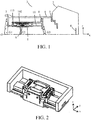
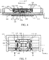
- FIGs. 2 to 5 are respectively a perspective view, an exploded perspective view, a sectional view of main components, and a top view of the ultrasonic motor 1 according to this embodiment.
- a friction member (contacting member) 104 and a guide supporting member 113 are fixed to the base plate 115 with screws.
- Four pressing springs (pressing members) 111 are each coupled to a pressing force transmission member (transmission member) 110 and a driving force transmission member 112 through coupling holding parts that the pressing force transmission member 110 and the driving force transmission member 112 each include.
- Tension spring force is generated between the pressing force transmission member 110 and the driving force transmission member 112, and draws the pressing force transmission member 110 in a direction shown as an arrow A.
- a pressing mechanism to press a vibrator 100 onto the friction member 104 includes the pressing springs 111, the pressing force transmission member 110, and the driving force transmission member 112.
- the pressing force transmission member 110 includes a pressing part 110a formed as an approximately hemispherical protruding part, and, to prevent damage to a piezoelectric element 103, an elastic member 109 is arranged between the piezoelectric element 103 and the pressing part 110a so that they do not directly contact with each other.
- the pressing springs 111 presses the vibrator 100 in the direction shown as the arrow A through these members.
- a pressure contact part 100a which is a protruding part formed on a surface opposite to a surface on a pressing force transmission member 110 side of the vibrator 100, comes into frictional contact with the friction member 104.
- the pressing springs 111 press the vibrator 100 at four positions, but the present invention is not limited to this as long as a plurality of pressing members can press the vibrator 100 at different positions. Furthermore, in this embodiment, the springs are used as the pressing members, but the present invention is not limited to this as long as the vibrator 100 can be pressed onto the friction member 104.
- the vibrator 100 includes a vibration plate 101, and the piezoelectric element 103 adhered to the vibration plate 101 by an adhesive.
- the vibration plate 101 is fixed to the vibrator holding member 102 using a welding or an adhesive.
- the piezoelectric element 103 excites ultrasonic vibration by being applied with a high frequency voltage.
- the piezoelectric element 103 which is adhered to the vibration plate 101, excites the ultrasonic vibration, a resonance phenomenon occurs on the vibrator 100. That is, the vibrator 100 generates the ultrasonic vibration by being applied with the high frequency voltage.
- approximately elliptical vibration occurs at an end of the pressure contact part 100a formed on the vibrator 100.
- Changing a frequency and a phase of the high frequency voltage applied to the piezoelectric element 103 can vary a rotational direction and an elliptical ratio appropriately, and thus a desired vibration can be generated. Accordingly, pressing the vibrator 100 onto the friction member 104 generates the driving force for relatively moving them, and thus the vibrator 100 can move along the x-axis (optical axis O) with respect to the friction member 104.
- a relative movement direction of the vibrator 100 is orthogonal to a pressing direction of the pressing springs 111 presses.
- a coupling member 116 which includes rollers (rolling members) 106a, 106b and a plate spring (urging member) 107 having predetermined elasticity, is incorporated between the vibrator holding member 102 and a holding housing 105 to hold the pressing force transmission member 110.
- the roller 106a is sandwiched between the plate spring 107 and the vibrator holding member 102 to be movable in the direction shown as the arrow A (pressing direction of the pressing springs 111).
- the plate spring 107 is arranged between the holding housing 105 and the roller 106a, and has urging force parallel to the x-axis.
- the plate spring 107 urges the vibrator holding member 102 in a direction shown as an arrow B through the roller 106a, and urges the holding housing 105 in a direction shown as an arrow C.
- the roller 106b is sandwiched between the vibrator holding member 102 and the holding housing 105.
- the coupling member 116 causes no backlash in the direction parallel to the x-axis (movement direction of the vibrator 100), and suppresses sliding resistance in the direction shown as the arrow A (pressing direction of the pressing springs 111) by action of the rollers 106a and 106b.
- the urging force of the plate spring 107 is set to be larger than inertial force by acceleration and deceleration generated in starting and stopping drive of the holding housing 105 and a driven part. Whereby, a relative displacement along the movement direction of the vibrator 100 by the inertial force during driving is not generated among the vibrator 100, the vibrator holding member 102 and the holding housing 105, and thus stable driving control can be realized.
- the rollers 106a and 106b are used as the rolling member included in the coupling member 116, but the present invention is not limited to this as long as the coupling member 116 is enabled to move in the direction shown as the arrow A.
- bolls may be used instead of the rollers.
- the plate spring 107 is used as the urging member included in the coupling member 116, but the present invention is not limited to this as long as no backlash between the vibrator holding member 102 and the holding housing 105 is generated.
- the driving force transmission member 112 is fixed to the holding housing 105 by an adhesive or screwing, and transmits the driving force generated in the vibrator 100.
- three V-grooves (moving side guiding parts), where rolling balls (guide members) 114a to 114c are inserted, are formed to guide the holding housing 105 along the x-axis (optical axis O).
- the guide supporting member 113 is arranged under the friction member 104.
- the friction member 104 and the guide supporting member 113 are fixed to the base plate 115 with screws.
- three groove-shaped fixed side guiding parts are formed on the guide supporting member 113.
- the rolling balls 114a to 114c are each sandwiched between the moving side guiding part formed on the driving force transmission member 112 and the fixed side guiding part formed on the guide supporting member 113.
- the holding housing 105 is supported to be movable forward or backward along the x-axis (optical axis O).
- two are V-grooves and one is a plane groove having a bottom, but they may be grooves capable of rolling the rolling balls 114.
- the pressing springs 111 are arranged separately to surround the vibrator 100 instead of being stacked on an upper part of the vibrator 100. In this embodiment, generating the pressing force by the plurality of pressing springs 111 can miniaturize the pressing springs 111. Additionally, the vibrator 100 is preferable pressed onto the friction member 104 uniformly. In this embodiment, as illustrated in FIG.5 , the pressing springs 111 are arranged separately to surround the pressure contact part 100a of the vibrator 100 when the ultrasonic motor 1 is viewed from top with respect to an X-Y plane.
- the coupling member (the rollers 106a, 106b and the plate spring 107) 116 is arranged between the pressing springs 111 (at a position closer to the pressure contact part 100a than the pressing springs 111) in the direction parallel to the x-axis (movement direction of the vibrator 100) and in the direction parallel to the y-axis. That is, the pressing springs 111 are arranged outside the coupling member 116 around the vibrator 100 in the directions parallel to the x-axis and y-axis.
- the direction parallel to the y-axis is the direction orthogonal to both of the movement direction of the vibrator 100 and the pressing direction of the pressing springs 111.
- the direction parallel to the y-axis need not be strictly orthogonal to the above directions, and is regarded as substantially orthogonal to the above directions even when shifting by a few degrees.
- FIG. 6 is a sectional view taken along D-D of FIG. 5 .
- the coupling holding parts 110b of the pressing force transmission member 110 that couples and holds the pressing springs 111, the pressing part 110a of the pressing force transmission member 110, and the coupling member 116 are arranged at the same position on the dashed line E in the figure. They need not be strictly arranged at the same position, and are deemed to be arranged at substantially the same position even when shifting by a few mm.
- the ultrasonic motor 1 can be miniaturized while providing the pressing mechanism that presses the vibrator onto the friction member and the mechanism that is provided to be movable in the pressing direction without any backlash in the driving direction.
- the coupling member 116 is arranged between the pressing springs 111 in the directions parallel to the x-axis and the y-axis, but may be arranged between the pressing springs 111 only in the direction parallel to the x-axis, or may be arranged between the pressing springs 111 only in the direction parallel to the y-axis. With any structure, an effect of miniaturization can be obtained.
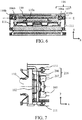
- FIG. 7 is an enlarged view of main components of an ultrasonic motor 1 according to this embodiment.
- the same members as the first embodiment are designated by the same reference numerals, and members different from that in the first embodiment are respectively designated by new reference numerals.
- a coupling member 216 includes a roller (rolling member) 206 and a plate spring (urging member) 207.
- the roller 206 has a length in the direction parallel to the y-axis (longitudinal direction) longer than that of the roller 106a in the first embodiment.
- the plate spring 207 which urges the roller 206, has a length in the direction parallel to the y-axis (longitudinal direction) longer than that of the plate spring 107 in the first embodiment. Lengthening the length in the longitudinal direction of the plate spring 207 can reduce a difficulty level of design of the plate spring 207.
- the coupling member 216 which includes the roller 206 and the plate spring 207, contacts with the pressing force transmission member 110 in the direction parallel to the y-axis (longitudinal direction). That is, the holding housing 105 positions the coupling member 116 in the longitudinal direction in the first embodiment, but the pressing force transmission member 110 positions the coupling member 216 in the longitudinal direction in this embodiment.
- the ultrasonic motor 1 has the structure that the vibrator 100 moves and the friction member 104 does not move, but may have the structure that the vibrator 100 does not move and the friction member 104 moves.
- the ultrasonic motor 1 includes the friction member 104 as the fixed member that does not move, but may not include the friction member 104 in the case where the vibrator 100 comes into frictional contact with the member other than the ultrasonic motor 1 (for example, part of the lens holding frame).
Landscapes
- Physics & Mathematics (AREA)
- General Physics & Mathematics (AREA)
- Optics & Photonics (AREA)
- General Electrical Machinery Utilizing Piezoelectricity, Electrostriction Or Magnetostriction (AREA)
- Lens Barrels (AREA)
- Motor Or Generator Frames (AREA)
Priority Applications (1)
| Application Number | Priority Date | Filing Date | Title |
|---|---|---|---|
| EP18206409.7A EP3490133B1 (en) | 2016-04-28 | 2017-04-26 | Motor and electronic apparatus including motor |
Applications Claiming Priority (1)
| Application Number | Priority Date | Filing Date | Title |
|---|---|---|---|
| JP2016090705A JP6808345B2 (ja) | 2016-04-28 | 2016-04-28 | 振動波モータおよび振動波モータが搭載された電子機器、レンズ鏡筒、撮像装置 |
Related Child Applications (2)
| Application Number | Title | Priority Date | Filing Date |
|---|---|---|---|
| EP18206409.7A Division-Into EP3490133B1 (en) | 2016-04-28 | 2017-04-26 | Motor and electronic apparatus including motor |
| EP18206409.7A Division EP3490133B1 (en) | 2016-04-28 | 2017-04-26 | Motor and electronic apparatus including motor |
Publications (2)
| Publication Number | Publication Date |
|---|---|
| EP3240180A1 EP3240180A1 (en) | 2017-11-01 |
| EP3240180B1 true EP3240180B1 (en) | 2019-01-02 |
Family
ID=58671394
Family Applications (2)
| Application Number | Title | Priority Date | Filing Date |
|---|---|---|---|
| EP17168104.2A Active EP3240180B1 (en) | 2016-04-28 | 2017-04-26 | Motor and electronic apparatus including motor |
| EP18206409.7A Active EP3490133B1 (en) | 2016-04-28 | 2017-04-26 | Motor and electronic apparatus including motor |
Family Applications After (1)
| Application Number | Title | Priority Date | Filing Date |
|---|---|---|---|
| EP18206409.7A Active EP3490133B1 (en) | 2016-04-28 | 2017-04-26 | Motor and electronic apparatus including motor |
Country Status (10)
| Country | Link |
|---|---|
| US (1) | US10840828B2 (zh) |
| EP (2) | EP3240180B1 (zh) |
| JP (1) | JP6808345B2 (zh) |
| KR (1) | KR102137195B1 (zh) |
| CN (2) | CN107342703B (zh) |
| BR (1) | BR102017007837B1 (zh) |
| PH (1) | PH12017000138A1 (zh) |
| RU (1) | RU2671943C2 (zh) |
| SG (1) | SG10201703315TA (zh) |
| TW (1) | TWI643440B (zh) |
Families Citing this family (11)
| Publication number | Priority date | Publication date | Assignee | Title |
|---|---|---|---|---|
| US10763763B2 (en) * | 2016-04-28 | 2020-09-01 | Canon Kabushiki Kaisha | Motor and electronic apparatus including motor |
| JP6808345B2 (ja) | 2016-04-28 | 2021-01-06 | キヤノン株式会社 | 振動波モータおよび振動波モータが搭載された電子機器、レンズ鏡筒、撮像装置 |
| JP6910936B2 (ja) | 2017-11-27 | 2021-07-28 | キヤノン株式会社 | 振動型モータ、レンズ装置、および、電子機器 |
| JP6605012B2 (ja) * | 2017-12-08 | 2019-11-13 | キヤノン株式会社 | 振動波モータ及び振動波モータを用いたレンズ駆動装置 |
| JP7007943B2 (ja) * | 2018-02-08 | 2022-01-25 | キヤノン株式会社 | 振動波モータ及び振動波モータを備えたレンズ駆動装置 |
| JP2019146434A (ja) * | 2018-02-23 | 2019-08-29 | キヤノン株式会社 | 振動波モータ及びレンズ駆動装置 |
| JP2019195233A (ja) * | 2018-05-01 | 2019-11-07 | キヤノン株式会社 | 振動波モータ及び振動波モータを用いた駆動装置 |
| JP7112250B2 (ja) | 2018-05-24 | 2022-08-03 | キヤノン株式会社 | 振動波モータ及び駆動装置 |
| JP7098438B2 (ja) * | 2018-06-26 | 2022-07-11 | キヤノン株式会社 | 振動波モータ及び振動波モータを用いた駆動装置 |
| CN110601593A (zh) * | 2019-09-27 | 2019-12-20 | 长春工业大学 | 一种上置定子式自定心微纳压电直线驱动器 |
| CN111600505B (zh) * | 2020-05-27 | 2021-11-12 | 东华大学 | 一种可调负荷大步进幅值直线压电电机 |
Family Cites Families (21)
| Publication number | Priority date | Publication date | Assignee | Title |
|---|---|---|---|---|
| JPH05252764A (ja) | 1992-03-05 | 1993-09-28 | Nikon Corp | 超音波モータ |
| JP4327268B2 (ja) * | 1998-06-01 | 2009-09-09 | セイコーインスツル株式会社 | 超音波モータ及び超音波モータ付電子機器 |
| JP4512408B2 (ja) * | 2004-04-26 | 2010-07-28 | オリンパス株式会社 | 振動波リニアモータ及びそれを用いたレンズ装置 |
| JP2008178250A (ja) | 2007-01-19 | 2008-07-31 | Olympus Corp | 超音波振動子の押圧機構および超音波モータ |
| JP5117058B2 (ja) * | 2007-01-26 | 2013-01-09 | 太平洋セメント株式会社 | アクチュエータケースおよび超音波モータ |
| JP5185684B2 (ja) * | 2008-04-25 | 2013-04-17 | オリンパスイメージング株式会社 | 駆動装置および撮像装置 |
| JP2011166919A (ja) * | 2010-02-09 | 2011-08-25 | Olympus Corp | 超音波モータ機構 |
| JP5810303B2 (ja) * | 2010-04-06 | 2015-11-11 | パナソニックIpマネジメント株式会社 | 駆動装置 |
| US8643252B2 (en) * | 2010-05-11 | 2014-02-04 | Canon Kabushiki Kaisha | Vibration wave actuator |
| JP5744670B2 (ja) * | 2011-08-05 | 2015-07-08 | キヤノン株式会社 | 超音波モータ及びそれを有するレンズ装置 |
| JP5773900B2 (ja) * | 2012-01-30 | 2015-09-02 | キヤノン株式会社 | モータ |
| CN103684036A (zh) | 2012-09-18 | 2014-03-26 | 精工爱普生株式会社 | 压电马达、机器人手、机器人、电子部件搬运装置、电子部件检查装置、送液泵、打印装置 |
| JP6188366B2 (ja) * | 2013-03-21 | 2017-08-30 | キヤノン株式会社 | アクチュエータ及び光学機器 |
| JP5955347B2 (ja) | 2013-04-01 | 2016-07-20 | キヤノン株式会社 | リニア超音波モータ及びそれを用いた光学装置 |
| JP5969976B2 (ja) * | 2013-12-27 | 2016-08-17 | キヤノン株式会社 | 振動波モータ |
| JP2016036233A (ja) * | 2014-08-04 | 2016-03-17 | キヤノン株式会社 | 振動型アクチュエータ、光学機器、及び撮像装置 |
| US9653675B2 (en) * | 2014-10-10 | 2017-05-16 | Canon Kabushiki Kaisha | Driving apparatus, lens apparatus including the same, and imaging apparatus |
| JP6489940B2 (ja) * | 2015-05-28 | 2019-03-27 | キヤノン株式会社 | 振動波モータ |
| JP6539117B2 (ja) * | 2015-05-29 | 2019-07-03 | キヤノン株式会社 | 振動波モータ |
| JP6305377B2 (ja) * | 2015-08-04 | 2018-04-04 | キヤノン株式会社 | 振動型アクチュエータ、装置および光学機器 |
| JP6808345B2 (ja) | 2016-04-28 | 2021-01-06 | キヤノン株式会社 | 振動波モータおよび振動波モータが搭載された電子機器、レンズ鏡筒、撮像装置 |
-
2016
- 2016-04-28 JP JP2016090705A patent/JP6808345B2/ja active Active
-
2017
- 2017-04-07 TW TW106111750A patent/TWI643440B/zh active
- 2017-04-17 BR BR102017007837-0A patent/BR102017007837B1/pt active IP Right Grant
- 2017-04-19 RU RU2017113514A patent/RU2671943C2/ru active
- 2017-04-20 KR KR1020170050752A patent/KR102137195B1/ko active IP Right Grant
- 2017-04-21 PH PH12017000138A patent/PH12017000138A1/en unknown
- 2017-04-24 SG SG10201703315TA patent/SG10201703315TA/en unknown
- 2017-04-25 US US15/496,780 patent/US10840828B2/en active Active
- 2017-04-26 EP EP17168104.2A patent/EP3240180B1/en active Active
- 2017-04-26 EP EP18206409.7A patent/EP3490133B1/en active Active
- 2017-04-28 CN CN201710293705.0A patent/CN107342703B/zh active Active
- 2017-04-28 CN CN201910354438.2A patent/CN110112953B/zh active Active
Non-Patent Citations (1)
| Title |
|---|
| None * |
Also Published As
| Publication number | Publication date |
|---|---|
| SG10201703315TA (en) | 2017-11-29 |
| RU2671943C2 (ru) | 2018-11-08 |
| US10840828B2 (en) | 2020-11-17 |
| TWI643440B (zh) | 2018-12-01 |
| CN107342703A (zh) | 2017-11-10 |
| RU2017113514A (ru) | 2018-10-19 |
| RU2017113514A3 (zh) | 2018-10-19 |
| JP2017200361A (ja) | 2017-11-02 |
| US20170317614A1 (en) | 2017-11-02 |
| KR102137195B1 (ko) | 2020-07-23 |
| CN110112953A (zh) | 2019-08-09 |
| EP3240180A1 (en) | 2017-11-01 |
| KR20170123243A (ko) | 2017-11-07 |
| CN110112953B (zh) | 2020-06-12 |
| BR102017007837B1 (pt) | 2023-12-12 |
| BR102017007837A2 (pt) | 2017-10-31 |
| PH12017000138B1 (en) | 2019-01-21 |
| CN107342703B (zh) | 2019-11-29 |
| PH12017000138A1 (en) | 2019-01-21 |
| EP3490133B1 (en) | 2021-12-01 |
| EP3490133A1 (en) | 2019-05-29 |
| TW201739165A (zh) | 2017-11-01 |
| JP6808345B2 (ja) | 2021-01-06 |
Similar Documents
| Publication | Publication Date | Title |
|---|---|---|
| EP3240180B1 (en) | Motor and electronic apparatus including motor | |
| JP5955347B2 (ja) | リニア超音波モータ及びそれを用いた光学装置 | |
| US10247902B2 (en) | Motor and apparatus using the same | |
| JP6366674B2 (ja) | 振動波モータ | |
| US10804820B2 (en) | Motor and apparatus using the same | |
| JP2017034900A (ja) | 振動型アクチュエータ、装置および光学機器 | |
| JP2017200366A (ja) | 振動波モータおよび振動波モータが搭載された電子機器 | |
| US11101749B2 (en) | Vibration wave motor and imaging device having vibration wave motor | |
| EP3240179B1 (en) | Motor and electronic apparatus including motor | |
| JP6929165B2 (ja) | 振動波モータおよび駆動装置 | |
| JP2019198227A (ja) | アクチュエータ、装置 | |
| US11502625B2 (en) | Vibration wave motor, and driving apparatus having the same | |
| JP2020005374A (ja) | 振動型モータおよび駆動装置 | |
| JP6869727B2 (ja) | 振動波モータ | |
| JP2019083664A (ja) | 振動波モータ、レンズ装置、および、撮像装置 | |
| JP2019201465A (ja) | 振動波モータ及び駆動装置 |
Legal Events
| Date | Code | Title | Description |
|---|---|---|---|
| PUAI | Public reference made under article 153(3) epc to a published international application that has entered the european phase |
Free format text: ORIGINAL CODE: 0009012 |
|
| STAA | Information on the status of an ep patent application or granted ep patent |
Free format text: STATUS: THE APPLICATION HAS BEEN PUBLISHED |
|
| AK | Designated contracting states |
Kind code of ref document: A1 Designated state(s): AL AT BE BG CH CY CZ DE DK EE ES FI FR GB GR HR HU IE IS IT LI LT LU LV MC MK MT NL NO PL PT RO RS SE SI SK SM TR |
|
| AX | Request for extension of the european patent |
Extension state: BA ME |
|
| STAA | Information on the status of an ep patent application or granted ep patent |
Free format text: STATUS: REQUEST FOR EXAMINATION WAS MADE |
|
| 17P | Request for examination filed |
Effective date: 20180502 |
|
| RBV | Designated contracting states (corrected) |
Designated state(s): AL AT BE BG CH CY CZ DE DK EE ES FI FR GB GR HR HU IE IS IT LI LT LU LV MC MK MT NL NO PL PT RO RS SE SI SK SM TR |
|
| GRAP | Despatch of communication of intention to grant a patent |
Free format text: ORIGINAL CODE: EPIDOSNIGR1 |
|
| STAA | Information on the status of an ep patent application or granted ep patent |
Free format text: STATUS: GRANT OF PATENT IS INTENDED |
|
| RIC1 | Information provided on ipc code assigned before grant |
Ipc: H02N 2/02 20060101ALI20180626BHEP Ipc: H02N 2/00 20060101AFI20180626BHEP Ipc: H02N 2/04 20060101ALI20180626BHEP |
|
| INTG | Intention to grant announced |
Effective date: 20180711 |
|
| GRAS | Grant fee paid |
Free format text: ORIGINAL CODE: EPIDOSNIGR3 |
|
| GRAA | (expected) grant |
Free format text: ORIGINAL CODE: 0009210 |
|
| STAA | Information on the status of an ep patent application or granted ep patent |
Free format text: STATUS: THE PATENT HAS BEEN GRANTED |
|
| AK | Designated contracting states |
Kind code of ref document: B1 Designated state(s): AL AT BE BG CH CY CZ DE DK EE ES FI FR GB GR HR HU IE IS IT LI LT LU LV MC MK MT NL NO PL PT RO RS SE SI SK SM TR |
|
| REG | Reference to a national code |
Ref country code: GB Ref legal event code: FG4D |
|
| REG | Reference to a national code |
Ref country code: CH Ref legal event code: EP Ref country code: AT Ref legal event code: REF Ref document number: 1085688 Country of ref document: AT Kind code of ref document: T Effective date: 20190115 |
|
| REG | Reference to a national code |
Ref country code: IE Ref legal event code: FG4D |
|
| REG | Reference to a national code |
Ref country code: DE Ref legal event code: R096 Ref document number: 602017001640 Country of ref document: DE |
|
| REG | Reference to a national code |
Ref country code: NL Ref legal event code: MP Effective date: 20190102 |
|
| REG | Reference to a national code |
Ref country code: LT Ref legal event code: MG4D |
|
| REG | Reference to a national code |
Ref country code: AT Ref legal event code: MK05 Ref document number: 1085688 Country of ref document: AT Kind code of ref document: T Effective date: 20190102 |
|
| PG25 | Lapsed in a contracting state [announced via postgrant information from national office to epo] |
Ref country code: NL Free format text: LAPSE BECAUSE OF FAILURE TO SUBMIT A TRANSLATION OF THE DESCRIPTION OR TO PAY THE FEE WITHIN THE PRESCRIBED TIME-LIMIT Effective date: 20190102 |
|
| PG25 | Lapsed in a contracting state [announced via postgrant information from national office to epo] |
Ref country code: LT Free format text: LAPSE BECAUSE OF FAILURE TO SUBMIT A TRANSLATION OF THE DESCRIPTION OR TO PAY THE FEE WITHIN THE PRESCRIBED TIME-LIMIT Effective date: 20190102 Ref country code: PL Free format text: LAPSE BECAUSE OF FAILURE TO SUBMIT A TRANSLATION OF THE DESCRIPTION OR TO PAY THE FEE WITHIN THE PRESCRIBED TIME-LIMIT Effective date: 20190102 Ref country code: PT Free format text: LAPSE BECAUSE OF FAILURE TO SUBMIT A TRANSLATION OF THE DESCRIPTION OR TO PAY THE FEE WITHIN THE PRESCRIBED TIME-LIMIT Effective date: 20190502 Ref country code: NO Free format text: LAPSE BECAUSE OF FAILURE TO SUBMIT A TRANSLATION OF THE DESCRIPTION OR TO PAY THE FEE WITHIN THE PRESCRIBED TIME-LIMIT Effective date: 20190402 Ref country code: FI Free format text: LAPSE BECAUSE OF FAILURE TO SUBMIT A TRANSLATION OF THE DESCRIPTION OR TO PAY THE FEE WITHIN THE PRESCRIBED TIME-LIMIT Effective date: 20190102 Ref country code: SE Free format text: LAPSE BECAUSE OF FAILURE TO SUBMIT A TRANSLATION OF THE DESCRIPTION OR TO PAY THE FEE WITHIN THE PRESCRIBED TIME-LIMIT Effective date: 20190102 Ref country code: ES Free format text: LAPSE BECAUSE OF FAILURE TO SUBMIT A TRANSLATION OF THE DESCRIPTION OR TO PAY THE FEE WITHIN THE PRESCRIBED TIME-LIMIT Effective date: 20190102 |
|
| PG25 | Lapsed in a contracting state [announced via postgrant information from national office to epo] |
Ref country code: RS Free format text: LAPSE BECAUSE OF FAILURE TO SUBMIT A TRANSLATION OF THE DESCRIPTION OR TO PAY THE FEE WITHIN THE PRESCRIBED TIME-LIMIT Effective date: 20190102 Ref country code: GR Free format text: LAPSE BECAUSE OF FAILURE TO SUBMIT A TRANSLATION OF THE DESCRIPTION OR TO PAY THE FEE WITHIN THE PRESCRIBED TIME-LIMIT Effective date: 20190403 Ref country code: HR Free format text: LAPSE BECAUSE OF FAILURE TO SUBMIT A TRANSLATION OF THE DESCRIPTION OR TO PAY THE FEE WITHIN THE PRESCRIBED TIME-LIMIT Effective date: 20190102 Ref country code: LV Free format text: LAPSE BECAUSE OF FAILURE TO SUBMIT A TRANSLATION OF THE DESCRIPTION OR TO PAY THE FEE WITHIN THE PRESCRIBED TIME-LIMIT Effective date: 20190102 Ref country code: BG Free format text: LAPSE BECAUSE OF FAILURE TO SUBMIT A TRANSLATION OF THE DESCRIPTION OR TO PAY THE FEE WITHIN THE PRESCRIBED TIME-LIMIT Effective date: 20190402 Ref country code: IS Free format text: LAPSE BECAUSE OF FAILURE TO SUBMIT A TRANSLATION OF THE DESCRIPTION OR TO PAY THE FEE WITHIN THE PRESCRIBED TIME-LIMIT Effective date: 20190502 |
|
| REG | Reference to a national code |
Ref country code: DE Ref legal event code: R097 Ref document number: 602017001640 Country of ref document: DE |
|
| PG25 | Lapsed in a contracting state [announced via postgrant information from national office to epo] |
Ref country code: AL Free format text: LAPSE BECAUSE OF FAILURE TO SUBMIT A TRANSLATION OF THE DESCRIPTION OR TO PAY THE FEE WITHIN THE PRESCRIBED TIME-LIMIT Effective date: 20190102 Ref country code: CZ Free format text: LAPSE BECAUSE OF FAILURE TO SUBMIT A TRANSLATION OF THE DESCRIPTION OR TO PAY THE FEE WITHIN THE PRESCRIBED TIME-LIMIT Effective date: 20190102 Ref country code: AT Free format text: LAPSE BECAUSE OF FAILURE TO SUBMIT A TRANSLATION OF THE DESCRIPTION OR TO PAY THE FEE WITHIN THE PRESCRIBED TIME-LIMIT Effective date: 20190102 Ref country code: RO Free format text: LAPSE BECAUSE OF FAILURE TO SUBMIT A TRANSLATION OF THE DESCRIPTION OR TO PAY THE FEE WITHIN THE PRESCRIBED TIME-LIMIT Effective date: 20190102 Ref country code: DK Free format text: LAPSE BECAUSE OF FAILURE TO SUBMIT A TRANSLATION OF THE DESCRIPTION OR TO PAY THE FEE WITHIN THE PRESCRIBED TIME-LIMIT Effective date: 20190102 Ref country code: EE Free format text: LAPSE BECAUSE OF FAILURE TO SUBMIT A TRANSLATION OF THE DESCRIPTION OR TO PAY THE FEE WITHIN THE PRESCRIBED TIME-LIMIT Effective date: 20190102 Ref country code: SK Free format text: LAPSE BECAUSE OF FAILURE TO SUBMIT A TRANSLATION OF THE DESCRIPTION OR TO PAY THE FEE WITHIN THE PRESCRIBED TIME-LIMIT Effective date: 20190102 |
|
| PLBE | No opposition filed within time limit |
Free format text: ORIGINAL CODE: 0009261 |
|
| STAA | Information on the status of an ep patent application or granted ep patent |
Free format text: STATUS: NO OPPOSITION FILED WITHIN TIME LIMIT |
|
| PG25 | Lapsed in a contracting state [announced via postgrant information from national office to epo] |
Ref country code: SM Free format text: LAPSE BECAUSE OF FAILURE TO SUBMIT A TRANSLATION OF THE DESCRIPTION OR TO PAY THE FEE WITHIN THE PRESCRIBED TIME-LIMIT Effective date: 20190102 |
|
| 26N | No opposition filed |
Effective date: 20191003 |
|
| REG | Reference to a national code |
Ref country code: BE Ref legal event code: MM Effective date: 20190430 |
|
| PG25 | Lapsed in a contracting state [announced via postgrant information from national office to epo] |
Ref country code: LU Free format text: LAPSE BECAUSE OF NON-PAYMENT OF DUE FEES Effective date: 20190426 Ref country code: MC Free format text: LAPSE BECAUSE OF FAILURE TO SUBMIT A TRANSLATION OF THE DESCRIPTION OR TO PAY THE FEE WITHIN THE PRESCRIBED TIME-LIMIT Effective date: 20190102 |
|
| PG25 | Lapsed in a contracting state [announced via postgrant information from national office to epo] |
Ref country code: BE Free format text: LAPSE BECAUSE OF NON-PAYMENT OF DUE FEES Effective date: 20190430 Ref country code: SI Free format text: LAPSE BECAUSE OF FAILURE TO SUBMIT A TRANSLATION OF THE DESCRIPTION OR TO PAY THE FEE WITHIN THE PRESCRIBED TIME-LIMIT Effective date: 20190102 |
|
| PG25 | Lapsed in a contracting state [announced via postgrant information from national office to epo] |
Ref country code: TR Free format text: LAPSE BECAUSE OF FAILURE TO SUBMIT A TRANSLATION OF THE DESCRIPTION OR TO PAY THE FEE WITHIN THE PRESCRIBED TIME-LIMIT Effective date: 20190102 |
|
| PG25 | Lapsed in a contracting state [announced via postgrant information from national office to epo] |
Ref country code: IE Free format text: LAPSE BECAUSE OF NON-PAYMENT OF DUE FEES Effective date: 20190426 |
|
| REG | Reference to a national code |
Ref country code: CH Ref legal event code: PL |
|
| PG25 | Lapsed in a contracting state [announced via postgrant information from national office to epo] |
Ref country code: LI Free format text: LAPSE BECAUSE OF NON-PAYMENT OF DUE FEES Effective date: 20200430 Ref country code: CH Free format text: LAPSE BECAUSE OF NON-PAYMENT OF DUE FEES Effective date: 20200430 |
|
| PG25 | Lapsed in a contracting state [announced via postgrant information from national office to epo] |
Ref country code: CY Free format text: LAPSE BECAUSE OF FAILURE TO SUBMIT A TRANSLATION OF THE DESCRIPTION OR TO PAY THE FEE WITHIN THE PRESCRIBED TIME-LIMIT Effective date: 20190102 |
|
| PG25 | Lapsed in a contracting state [announced via postgrant information from national office to epo] |
Ref country code: MT Free format text: LAPSE BECAUSE OF FAILURE TO SUBMIT A TRANSLATION OF THE DESCRIPTION OR TO PAY THE FEE WITHIN THE PRESCRIBED TIME-LIMIT Effective date: 20190102 Ref country code: HU Free format text: LAPSE BECAUSE OF FAILURE TO SUBMIT A TRANSLATION OF THE DESCRIPTION OR TO PAY THE FEE WITHIN THE PRESCRIBED TIME-LIMIT; INVALID AB INITIO Effective date: 20170426 |
|
| PG25 | Lapsed in a contracting state [announced via postgrant information from national office to epo] |
Ref country code: MK Free format text: LAPSE BECAUSE OF FAILURE TO SUBMIT A TRANSLATION OF THE DESCRIPTION OR TO PAY THE FEE WITHIN THE PRESCRIBED TIME-LIMIT Effective date: 20190102 |
|
| PGFP | Annual fee paid to national office [announced via postgrant information from national office to epo] |
Ref country code: GB Payment date: 20240320 Year of fee payment: 8 |
|
| PGFP | Annual fee paid to national office [announced via postgrant information from national office to epo] |
Ref country code: IT Payment date: 20240320 Year of fee payment: 8 Ref country code: FR Payment date: 20240320 Year of fee payment: 8 |
|
| PGFP | Annual fee paid to national office [announced via postgrant information from national office to epo] |
Ref country code: DE Payment date: 20240320 Year of fee payment: 8 |