EP3229059A1 - Freischwebende bildanzeigevorrichtung - Google Patents
Freischwebende bildanzeigevorrichtung Download PDFInfo
- Publication number
- EP3229059A1 EP3229059A1 EP15865042.4A EP15865042A EP3229059A1 EP 3229059 A1 EP3229059 A1 EP 3229059A1 EP 15865042 A EP15865042 A EP 15865042A EP 3229059 A1 EP3229059 A1 EP 3229059A1
- Authority
- EP
- European Patent Office
- Prior art keywords
- display device
- image display
- aerial image
- retroreflector
- polarizing plate
- Prior art date
- Legal status (The legal status is an assumption and is not a legal conclusion. Google has not performed a legal analysis and makes no representation as to the accuracy of the status listed.)
- Withdrawn
Links
Images


Classifications
-
- G—PHYSICS
- G02—OPTICS
- G02B—OPTICAL ELEMENTS, SYSTEMS OR APPARATUS
- G02B30/00—Optical systems or apparatus for producing three-dimensional [3D] effects, e.g. stereoscopic images
- G02B30/50—Optical systems or apparatus for producing three-dimensional [3D] effects, e.g. stereoscopic images the image being built up from image elements distributed over a three-dimensional [3D] volume, e.g. voxels
- G02B30/56—Optical systems or apparatus for producing three-dimensional [3D] effects, e.g. stereoscopic images the image being built up from image elements distributed over a three-dimensional [3D] volume, e.g. voxels by projecting aerial or floating images
-
- G—PHYSICS
- G02—OPTICS
- G02B—OPTICAL ELEMENTS, SYSTEMS OR APPARATUS
- G02B27/00—Optical systems or apparatus not provided for by any of the groups G02B1/00 - G02B26/00, G02B30/00
- G02B27/28—Optical systems or apparatus not provided for by any of the groups G02B1/00 - G02B26/00, G02B30/00 for polarising
- G02B27/283—Optical systems or apparatus not provided for by any of the groups G02B1/00 - G02B26/00, G02B30/00 for polarising used for beam splitting or combining
-
- G—PHYSICS
- G02—OPTICS
- G02B—OPTICAL ELEMENTS, SYSTEMS OR APPARATUS
- G02B30/00—Optical systems or apparatus for producing three-dimensional [3D] effects, e.g. stereoscopic images
- G02B30/20—Optical systems or apparatus for producing three-dimensional [3D] effects, e.g. stereoscopic images by providing first and second parallax images to an observer's left and right eyes
- G02B30/22—Optical systems or apparatus for producing three-dimensional [3D] effects, e.g. stereoscopic images by providing first and second parallax images to an observer's left and right eyes of the stereoscopic type
- G02B30/25—Optical systems or apparatus for producing three-dimensional [3D] effects, e.g. stereoscopic images by providing first and second parallax images to an observer's left and right eyes of the stereoscopic type using polarisation techniques
-
- G—PHYSICS
- G02—OPTICS
- G02B—OPTICAL ELEMENTS, SYSTEMS OR APPARATUS
- G02B5/00—Optical elements other than lenses
- G02B5/12—Reflex reflectors
-
- G—PHYSICS
- G02—OPTICS
- G02B—OPTICAL ELEMENTS, SYSTEMS OR APPARATUS
- G02B5/00—Optical elements other than lenses
- G02B5/30—Polarising elements
- G02B5/3083—Birefringent or phase retarding elements
Definitions
- the present invention relates to an aerial image display device using a retroreflector.
- an aerial image display device which displays an image in the air by forming a display image from an image display device in the air attracts a lot of attention.
- An image-forming element is an essential element for an aerial image display device to form an image.
- aerial image display devices such as an aerial image display device in which a micro mirror image-forming element formed by a micro dihedral corner reflector array is used, an aerial image display device in which a retroreflective image-forming element formed by combining a half mirror and a retroreflector is used, and the like, are proposed (see PTL 1 to PTL 4, for example).
- the aerial image display device using micro mirror image-forming element can provide an aerial image with high-definition and high luminance.
- the problems with the aerial image display device using micro mirror image-forming element are that viewing angle is narrow; the stray light caused by the light reflected an odd number of times can be seen; and further, because hundreds of regular patterns in size of ⁇ m unit have to be formed, cost of the image-forming element is very high, and it is difficult to increase the area of the image-forming element.
- the aerial image display device using retroreflective image-forming element can solve the aforesaid problems of the aerial image display device using micro mirror image-forming element.
- the problem with the aerial image display device using retroreflective image-forming element is that the luminance of the aerial image formed thereby is low.
- a reflection-type polarizing plate that differentially reflects polarized light is used as the half mirror to improve light utilization efficiency of the aerial image, so as to increase the luminance (see PTL 5 to PTL 6, for example).
- the present invention is made to enable an aerial image display device using retroreflector to display a high-definition aerial image with sufficient luminance.
- An aerial image display device has the following configurations:
- the present invention it is possible to achieve a high-definition aerial image display device, in an aerial image display device using retroreflector.
- an aerial image display device with high luminance by the aforesaid means [1] to [3].
- the definition can be improved by the aforesaid means [4].
- the contrast can be improved by the aforesaid means [5].
- the hue can be improved by the aforesaid means [6].
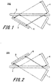
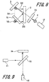
- FIG. 1 and FIG. 2 are schematic views (viewed from one side) each showing a general configuration of an aerial image display device according to the present invention.
- the aerial image display devices shown in FIG. 1 and FIG. 2 are each provided with an image display device 1, a half mirror 2, a retroreflector 3 and a ⁇ /4 plate 6.
- An aerial image display device 210 shown in FIG. 1 has a configuration in which the retroreflector 3 is arranged in a direction in which an image light emitted from the image display device 1 is reflected by the half mirror 2.
- the image light retroreflected by the retroreflector 3 reaches the half mirror 2 again, and the image light transmitted through the half mirror 2 forms an aerial image 4.
- An aerial image display device 220 shown in FIG. 2 has a configuration in which the retroreflector 3 is arranged in a direction in which an image light emitted from the image display device 1 transmits through the half mirror 2.
- the image light retroreflected by the retroreflector reaches the half mirror 2 again, and the image light reflected by the half mirror 2 forms the aerial image 4.
- the aerial image 4 is a real image formed at a position plane-symmetrical to the image display device 1 with the half mirror 2 as a symmetry center.
- the ⁇ /4 plate 6 is arranged on the surface of the retroreflector 3.
- the half mirror 2 is a reflection-type polarizing plate
- the retroreflector 3 has a polarization-maintaining degree of 50% or higher, preferably 95% or higher.
- the ⁇ /4 plate 6 is arranged on the surface of the retroreflector 3, and the retroreflector 3 has a polarization-maintaining degree of 50% or higher, preferably 95% or higher, it is possible to achieve high luminance.
- the aerial image display device has a configuration in which the ⁇ /4 plate 6 is bonded to the retroreflector 3 through a transparent adhesive, the reflection on the interface between the retroreflector 3 and the ⁇ /4 plate 6 will be inhibited, so that such a configuration can also lead to improvement of the luminance of the aerial image.
- the aerial image display device of the present invention is not necessarily to be limited to a configuration in which the ⁇ /4 plate is arranged on the retroreflector, but also includes a configuration in which the ⁇ /4 plate is interposed between the half mirror and the retroreflector.
- a half mirror is an optical element that allows a part of light incident thereon to be reflected thereby and the remaining part to be transmitted therethrough.
- the luminance of the aerial image can be improved by increasing the product of a normal reflectance Rp and a parallel light transmittance Tp of the half mirror.
- the half mirror include a colorless and transparent plate with less absorption, a metal thin-film plate (as a general half mirror), a dielectric multilayer plate (as a general half mirror), and a reflection-type polarizing plate by which two orthogonal polarized lights can be separated from each other.
- a reflection-type polarizing plate is used as the half mirror.
- a reflection-type polarizing plate has a reflective surface and a non-reflective surface.
- the reflection-type polarizing plate is arranged so that the reflective surface faces the lower side; and in the aerial image display device 220 shown in FIG. 2 , the reflection-type polarizing plate is arranged so that the reflective surface faces the upper side.
- a colorless and transparent plate may be bonded to the reflection-type polarizing plate of the half mirror through a transparent adhesive.
- the material of the colorless and transparent plate is not particularly limited as long as the material is colorless and transparent; however, it is preferred that the material has small refractive-index anisotropy.
- the colorless and transparent plate include a plastic film, a glass plate and the like, wherein examples of the plastic film include an acrylic film, a polyester film, a polycarbonate film and the like, and examples of the glass plate include an alkali glass, a quartz glass, a chemically strengthened glass, an alumina glass and the like.
- half mirror refers to an optical component having a function of separating the light emitted from the image display device and the light reflected from the retroreflector into different directions.
- the aforesaid function of separating the emitted light and the reflected light is achieved by the optical component arranged closest to the image display device, among the plurality of optical components.
- the reflection-type polarizing plate examples include a uniaxially stretched dielectric multilayer plate, a wire grid polarizing plate and a cholesteric liquid crystal plate, wherein the uniaxially stretched dielectric multilayer plate and the wire grid polarizing plate are each adapted to separate linearly polarized lights such as P-polarized light and S-polarized light, and the cholesteric liquid crystal plate is adapted to separate circularly polarized lights such as left circularly polarized light and right circularly polarized light.
- Examples of commercially available uniaxially stretched dielectric multilayer plate include, for example, DBEF (manufactured by 3M Corporation), a polarizing plate with APCF (luminance improving film) (manufactured by Nitto Denko Corporation), and the like.
- Examples of commercially available wire grid polarizing plate include, for example, WGF (manufactured by ASAHI KASEI E-materials Corporation), ProFluxPPL02 (manufactured by Moxtek, Inc.), and the like.
- Examples of commercially available cholesteric liquid crystal plate include, for example, NIPOCS APCF (manufactured by Nitto Denko Corporation), and the like.
- the luminance of the aerial image can be increased by providing a ⁇ /4 plate on the retroreflector. Further, by bonding a ⁇ /4 plate to the retroreflector through a transparent adhesive, reflection on the interface can be reduced, and therefore the luminance can be increased.
- a reverse wavelength dispersion type ⁇ /4 plate is preferred since it makes the hue of the aerial image closer to the hue of the image display device than a normal wavelength dispersion type ⁇ /4 plate.
- Examples of commercially available ⁇ /4 plate include a normal wavelength dispersion type ⁇ /4 plate such as Elmec R140, Elmec R40- # 140 (all manufactured by Kaneka Corporation), Pure Ace GT-138, Pure Ace GR-138, Pure Ace TT-140, Pure Ace GS-120 (all manufactured by Teijin Limited), and a reverse wavelength dispersion type ⁇ /4 plate such as Pure Ace WRS-148, Pure Ace WRW-142(all manufactured by Teijin Limited).
- the retroreflector of the aerial image display device has the same meaning as that of the retroreflector defined in JIS Z 8713: 1995, i.e., a reflector that causes the light reflected therefrom to selectively return almost along the optical path of the light incident thereon.
- the retroreflector is widely used as a road marker for maintaining traffic safety and making traffic smooth, or as safety equipment for preventing accidents from occurring during night or in a dark place, and there are various commercially available retroreflectors with different hues, which can be mainly classified into two types, one is a prism type, and the other one is microbead type.
- prism type retroreflector examples include Nikkalite Crystal Grade (manufactured by Nippon Carbide Industries Co., Inc.), Diamond Grade DG ultrabright reflective sheet 2090/4090 (manufactured by 3M Corporation), Reflexite 18605 (manufactured by Orafol Co. Ltd.), and the like.
- microbead type retroreflector examples include Scotchcal reflective sheet 1570, Scotchcal reflective sheet 680-10/85, Scotchlite high gain 7610, Scotchlite reflective cloth 8910 (all manufactured by 3M Corporation), Kiwalite 19513 (manufactured by Kiwa Chemical Industry Co., Ltd.), Sparklite MR501 (manufactured by Unitika Sparklite Ltd), Sparklite MR718BT (manufactured by Unitika Sparklite Ltd), Reflite 9301 (manufactured by Nihon Reflite Industry Co. Ltd.), Reflite 8318 (manufactured by Nihon Reflite Industry Co. Ltd.), and the like.
- the retroreflector in a three-dimensional shape, it will become possible to display a three-dimensional aerial image.
- the contrast of the aerial image can be improved by arranging an absorption-type polarizing plate on the half mirror. Further, by bonding an absorption-type polarizing plate to the half mirror through a transparent adhesive, reflection on the interface can be reduced, and therefore the luminance can be increased.
- the contrast may also be improved by providing a ND that simply reduces the amount of light; however, it is more preferable to provide an absorption-type polarizing plate.
- absorption-type polarizing plate examples include NPF-F1205DU, NPF-FW1225DU, NPF-G1220DUN, NPF-EGW1225DU, NPF-SEG1425DU, NPF-TEG1465DU (all manufactured by Nitto Denko Corporation), SUMIKALAN SR-W842, SUMIKALAN SR-W862A, SUMIKALAN SR-F862 (all manufactured by Sumitomo Chemical Co., Ltd).
- reflection-type polarizing plate with absorption-type polarizing plate it is preferred to use a reflection-type polarizing plate with absorption-type polarizing plate, so that the process for bonding the absorption-type polarizing plate can be omitted.
- Examples of commercially available reflection-type polarizing plate with absorption-type polarizing plate include a DBEF-Q (manufactured by 3M Corporation), a polarizing plate with APCF (manufactured by Nitto Denko Corporation), a NIPOCS APCF (manufactured by Nitto Denko Corporation), and the like.
- the absorption-type polarizing plate in the case where an absorption-type polarizing plate is provided, the absorption-type polarizing plate must be arranged on the side of the non-reflective surface of the reflection-type polarizing plate, and a colorless and transparent plate may be provided between the reflection-type polarizing plate and the absorption-type polarizing plate.
- a colorless and transparent plate may be provided between the reflection-type polarizing plate and the absorption-type polarizing plate.
- these components are bonded to each other through a transparent adhesive.
- the aerial image display device 210 shown in FIG. 1 it is necessary to arrange the absorption-type polarizing plate and the reflection-type polarizing plate so that the transmission axes thereof are parallel to each other; while in the aerial image display device 220 shown in FIG. 2 , it is necessary to arrange the absorption-type polarizing plate and the reflection-type polarizing plate so that the transmission axes thereof are perpendicular to each other.
- an aerial image display device 260 shown in FIG. 6 further has an absorption-type polarizing plate 7 arranged on the half mirror 2, which is a reflection-type polarizing plate.
- the absorption-type polarizing plate 7 By arranging the absorption-type polarizing plate 7 on the half mirror 2, the light reflected from the retroreflector 3 is transmitted through the absorption-type polarizing plate 7 only once, while external light incident on the half mirror 2 is transmitted through the absorption-type polarizing plate 7 twice. Thus, the external light is remarkably reduced, and therefore the contrast of the light reflected by from the retroreflector 3 can be improved.
- the absorption-type polarizing plate can be applied not only to the aerial image display device 210 shown in FIG. 1 , but also to other aerial image display devices without departing from the scope of the present invention.
- the absorption-type polarizing plate does not have to be arranged on the half mirror.
- the absorption-type polarizing plate may also be arranged between the half mirror and the observer.
- the absorption-type polarizing plate needs to be arranged in a position so that the external light is transmitted through the absorption-type polarizing plate twice.
- An aerial image display device 240 shown in FIG. 4 is an embodiment obtained by providing a light shielding wall 5 around the aerial image display device 220 shown in FIG. 2 .
- the side faces of the light shielding wall 5 are vertically formed, the bottom face and the top face of the light shielding wall 5 are horizontally formed, wherein the top face covers a portion ranging from the half mirror 2 to the aerial image 4 from above.
- an aerial image display device provided with a light shielding wall is not limited to the embodiments shown in FIGS. 3 to 5 , but also includes various modifications without departing from the scope of the present invention.
- fluctuation in hue of the aerial image (i.e., rainbow-like unevenness) of the aerial image display device can be inhibited by providing a depolarization element on the image display device.
- the fluctuation in hue of the aerial image i.e., rainbow-like unevenness
- the fluctuation in hue of the aerial image means a phenomenon in which unevenness of green color and magenta color in the aerial image is caused due to touch sensor film of the image display device.
- Examples of the image display device to which such phenomenon will occur include iPhone 5S (manufactured by Apple inc.), iPhone 5C (manufactured by Apple inc.), Xperia A2 (manufactured by Sony Ericsson), AQUOSZETASH-04F (manufactured by Sharp Corporation), and the like.
- Examples of commercially available depolarization element include, for example, Cosmoshine SRF (manufactured by Toyobo Co., Ltd.), depolarization adhesive (manufactured by Nagase & Co., Ltd.), and the like.
- a Cosmoshine SRF manufactured by Toyobo Co., Ltd.
- the depolarization element by bonding the adhesive to the image display device, reflection on the interface can be reduced, so that luminance can be increased.
- a depolarization adhesive manufactured by Nagase & Co., Ltd.
- it is used by bonding the colorless and transparent plate and the image display device to each other through the depolarization adhesive.
- FIG. 7 an embodiment in which a depolarization element is provided is shown in FIG. 7 .
- an aerial image display device 270 shown in FIG. 7 further has a depolarization element 8 arranged on the image display device 1.
- the hue of the aerial image can be improved.
- the aerial image display device of the present invention is not necessarily to be limited to a configuration in which the depolarization element is arranged on the image display device, but also includes a configuration in which the depolarization element is interposed between the image display device and the half mirror.
- the retroreflector since a reflection-type polarizing plate is used as the half mirror, it is preferred that the retroreflector has a high polarization-maintaining degree to thereby increase the luminance of the aerial image; to be specific, as described above, it is preferred that the retroreflector has a polarization-maintaining degree of 50% or higher, more preferably 95% or higher.
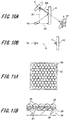
- the polarization-maintaining degree of the retroreflector is defined by Ip/(Ic+Ip), wherein Ip and Ic are measured using an optical system shown in FIG. 8 for example.
- the optical system shown in FIG. 8 includes an LED light source 10, the half mirror 2, the retroreflector 3, a luminance meter 12, a first absorption-type polarizing plate 15, and a second absorption-type polarizing plate 15, wherein the first absorption-type polarizing plate 15 is disposed between the LED light source 10 and the half mirror 2, and the second absorption-type polarizing plate 15 is disposed between the half mirror 2 and the aerial image 4; a distance D1 between the LED light source 10 and the retroreflector 3 is set to 175 mm, a distance D2 between the retroreflector 3 and the half mirror 2 is set to 75 mm, and a distance D3 between the LED light source 10 and the half mirror 2 is set to 75 mm.
- the luminance value of the aerial image measured by the luminance meter 12 is Ip; while when the two absorption-type polarizing plates 15 are arranged so that the directions of the transmission axes thereof are perpendicular to each other, the luminance value of the aerial image measured by the luminance meter 12 is Ic.
- the retroreflector has a high reflectance to thereby increase the luminance of the aerial image; to be specific, it is preferred that the retroreflector has a reflectance of 15% or higher, more preferably 20% or higher.
- the hue of the retroreflector is silver, white or black, it is more preferable more that the hue of the retroreflector is silver or white with high reflectance, and it is most preferable that the hue of the retroreflector is silver with high frontal reflectance.
- the reflectance of the retroreflector can be measured using an optical system shown in FIG. 9 for example.
- the optical system shown in FIG. 9 includes a light source 11, an illuminance meter 16, a beam splitter 13, and a reflector 14; the light emitted from the light source 11 is reflected by the beam splitter 13 and further reflected by the reflector 14, and the light reflected from the reflector 14 is transmitted through the beam splitter 13 and its luminance is measured by the illuminance meter 16.
- the retroreflector is not selected based on a general perception that a prism type retroreflector can achieve higher definition than a microbead type retroreflector, but is selected based on a confirmed fact that a high-definition aerial image can be achieved by using a retroreflector preferably with a spreading rate of ⁇ ⁇ 1.20%/mm, and more preferably with a spreading rate of ⁇ ⁇ 1.00%/mm.
- examples of commercially available retroreflector with a spreading rate of ⁇ ⁇ 1.20%/mm include a prism type retroreflector such as Nikkalite Crystal Grade white (manufactured by Nippon Carbide Industries Co., Inc.), Reflexite 18605 (manufactured by Orafol Co. Ltd.) and the like; among these products, the Nikkalite Crystal Grade white (manufactured by Nippon Carbide Industries Co., Inc.) is the most preferable.
- the definition of the aerial image according to the present invention can be further improved by using a retroreflector using microbeads with a refractive index of about 2.0.
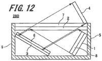
- FIG. 11A and FIG. 11B are schematic views showing an example of a retroreflector using microbeads with a refractive index of 2.0; wherein FIG. 11A is a plan view, and FIG. 11B is a cross-sectional view.
- microbeads 23 with a refractive index of about 2.0 are arranged on a resin layer 22 provided on a substrate 21, wherein the lower portion of the microbeads 23 is embedded in the resin layer 22.
- the microbeads 23 are arranged in the resin layer 22 so as to have a two-dimensional close-packed structure.
- the lower portion of the microbeads 23 forms a reflective layer 24.
- microbeads with a refractive index of 2.0 are not particularly limited as long as the microbeads have a refractive index of about 2.0; however, it is preferred that the refractive index of the microbeads is close to 2.0.
- Concrete examples of commercially available microbeads with a refractive index of 2.0 include microbeads K-PSFn1 with a refractive index of 1.9, microbeads K-PSFn2 with a refractive index of 2.0 (all manufactured by Sumita Optical Glass, Inc.) and the like; among these products, K-PSFn2 is preferable.
- the optical system shown in FIG. 10A includes a LED light source 10, a half mirror 2, a retroreflector 3, and a screen 17; a distance D1 between the LED light source 10 and the retroreflector 3 is set to 175 mm, a distance D2 between the retroreflector 3 and the half mirror 2 is set to 75 mm, and a distance D3 between the LED light source 10 and the half mirror 2 is set to 75 mm.
- S represents the size of the aerial image 4 measured in the optical system shown in FIG. 10A when the screen 17 is place in the position of the aerial image 4.
- the image display device is a device for displaying video signals of still images or moving images.
- Examples of the image display device according to the present invention include a cathode ray tube (CRT) display, a liquid crystal display (LCD), a plasma display (PDP), an organic EL display, an LED display, and the like.
- the aerial image display device of the present invention is suitable for displaying a large image, and is considered to be used as an aerial image billboard or the like. It is preferred that an LED display with high luminance, which is easily visible even in an environment where external light is bright, is used as the aerial image billboard.
- the resolution of the LED is preferably to be applied to usages to be viewed from a distant place, such as a billboard and the like, although the resolution thereof cannot be increased.
- a toy display which uses a personal smartphone or tablet, such as HAKO Vision (manufactured by Bandai Co., Ltd), attracts a lot of attention, and the aerial image display device according to the present invention can also be used for such purpose.
- a LCD or organic EL display which is widely used in smartphone or tablet, is used as the image display device.
- the aerial image display device since a reflection-type polarizing plate is used as the half mirror, it is preferred that an image display device whose image light is linearly polarized light or circularly polarized light is selected as the image display device, so that the reflectance Rp of the half mirror can be maximized.
- Examples of commercially available image display device whose image light is linearly polarized light include Xperia Z2 (manufactured by Sony Ericsson), NEXUS 5 (manufactured by Google) and the like; and examples of commercially available image display device whose image light is circularly polarized light include Galaxy S5 (manufactured by Samsung) and the like.
- a shell type green LED with a wavelength of 528 nm was used as the LED light source 10
- a plate type B/S50R/50T manufactured by Edmund Optics Inc.
- a SPF-30C-32 manufactured by Sigma Koki Co., Ltd.
- a CS-2000 manufactured by Konica Minolta Inc. was used as the luminance meter 12.
- a red laser 05LHP111 with a wavelength of 632.8 nm (manufactured by Melles Griot Inc.) was used as the He-Ne light source 11
- a LX2 (manufactured by Sanwa Electric Instrument Co., Ltd) was used as the illuminance meter 16
- a plate type B/S50R/50T (manufactured by Edmund Optics Inc.) was used as the beam splitter 13
- a wideband dielectric mirror BB1-E02 manufactured by Thorlabs inc.
- the absolute reflectance Rm of the mirror nm is 99.1%.
- a shell type green LED with a wavelength of 528 nm was used as the LED light source 10
- a plate type B/S50R/50T manufactured by Edmund Optics Inc.
- the size S0 of the LED light source 10 had been measured and found to be 1.7 mm.
- An image display device A was prepared by bonding a depolarization element Cosmoshine SRF 80 ⁇ m (manufactured by Toyobo Co., Ltd.) to an iPhone 5S (manufactured by Apple inc.) through a highly transparent adhesive transfer tape 8172CL (manufactured by 3M Corporation).
- An image display device B was prepared by bonding a SUMIPEX 000 (manufactured by Sumika Acryl Co., Ltd) to an iPhone 5S (manufactured by Apple inc.) through a depolarization adhesive (manufactured by Nagase & Co., Ltd.).
- a reflection-type polarizing plate A was prepared by bonding the non-reflective surface of a reflection-type polarizing plate WGF (manufactured by ASAHI KASEI E-materials Corporation) and an absorption-type polarizing plate NPF-SEG1425DU (manufactured by Nitto Denko Corporation) to each other through a highly transparent adhesive transfer tape 8172CL (manufactured by 3M Corporation).
- the reflection-type polarizing plate WGF and the absorption-type polarizing plate NPF-SEG1425DU were arranged so that the direction of the transmission axis of the reflection-type polarizing plate WGF and the direction of the transmission axis of the absorption-type polarizing plate NPF-SEG1425DU were parallel to each other.
- a reflection-type polarizing plate B was prepared by bonding a reflection-type polarizing plate with absorption-type polarizing plate DEBF-Q (manufactured by 3M Corporation) and a SUMIPEX 000 (manufactured by Sumika Acryl Co., Ltd) to each other through a highly transparent adhesive transfer tape 8172CL (manufactured by 3M Corporation), wherein the bonded surface of the DEBF-Q was a surface on the absorption-type polarizing plate side.
- DEBF-Q absorption-type polarizing plate
- SUMIPEX 000 manufactured by Sumika Acryl Co., Ltd
- a slide glass S1111 (manufactured by Matsunami Glass Industries, Co., Ltd.) was cut into 24 mm, and then washed in an ultrasound bath with acetone for 10 minutes and then with ethanol for 10 minutes; thereafter, a UV-curable optical adhesive NOA61 (manufactured by Norland Products Inc.) was applied to the slide glass to form a thickness of 0.5 mm.
- the 168 pieces of glass beads having been subjected to the aluminum deposition were laid on the slide glass with the aluminum-deposited side thereof facing downward to become a two-dimensional close-packed structure, and an ultraviolet irradiation device FP-35L having an output of 180 W (manufactured by Vilber Lourmat) was used to irradiate the slide glass and the glass beads to cure the optical adhesive, so that a retroreflector A was prepared.
- an ultraviolet irradiation device FP-35L having an output of 180 W manufactured by Vilber Lourmat
- glass beads K-PSFn1 manufactured by Sumita Optical Glass, Inc.
- An aerial image display device of Example 1 was prepared by, in the aerial image display device 250 shown in FIG. 5 , using an image display device A as the image display device 1, using a reflection-type polarizing plate A as the half mirror 2, using a retroreflector A as the retroreflector 3, and using a ⁇ /4 plate Pure Ace WRW-142 (manufactured by Teijin Limited) as the ⁇ /4 plate 6.
- the reflection-type polarizing plate A is arranged so that the reflective surface of the reflection-type polarizing plate A faces the side of the iPhone 5S (which is the image display device A), and the reflection axis of the reflection-type polarizing plate A forms an angle of 45° with respect to the slow axis of the ⁇ /4 plate 6.
- the aerial image display device of the present example uses the image display device A and the reflection-type polarizing plate A, it actually has a configuration of an aerial image display device 280 shown in FIG. 12 , in which a depolarization element 8 is arranged on an image display device 1, and an absorption-type polarizing plate 7 is formed on the non-reflective surface of the reflection-type polarizing plate of the half mirror 2.
- An aerial image display device of Example 2 was prepared in the same manner as Example 1 except that a retroreflector B was used as the retroreflector 3.
- An aerial image display device of Example 3 was prepared in the same manner as Example 1 except that a retroreflector Nikkalite Crystal Grade White (manufactured by Nippon Carbide Industries Co., Inc.) was used as the retroreflector 3.
- a retroreflector Nikkalite Crystal Grade White manufactured by Nippon Carbide Industries Co., Inc.
- An aerial image display device of Example 4 was prepared in the same manner as Example 1 except that a retroreflector Scotchlite reflective cloth 8910 (manufactured by 3M Corporation) was used as the retroreflector 3.
- An aerial image display device of Example 5 was prepared in the same manner as Example 1 except that a retroreflector Reflite 9301 (manufactured by Nihon Reflite Industry Co. Ltd.) was used as the retroreflector 3.
- a retroreflector Reflite 9301 manufactured by Nihon Reflite Industry Co. Ltd.
- An aerial image display device of Comparison 1 was prepared in the same manner as Example 1 except that a retroreflector Reflexite 18605 (manufactured by Orafol Co. Ltd.) was used as the retroreflector 3.
- An aerial image display device of Comparison 2 was prepared in the same manner as Example 1 except that a retroreflector Kiwalite 19513 (manufactured by Kiwa Chemical Industry Co., Ltd.) was used as the retroreflector 3.
- a retroreflector Kiwalite 19513 manufactured by Kiwa Chemical Industry Co., Ltd.
- An aerial image display device of Example 6 was prepared in the same manner as Example 1 except that a reflection-type polarizing plate WGF (manufactured by ASAHI KASEI E-materials Corporation) was used as the half mirror 2.
- a reflection-type polarizing plate WGF manufactured by ASAHI KASEI E-materials Corporation
- An aerial image display device of Example 7 was prepared in the same manner as Example 3 except that a reflection-type polarizing plate with absorption-type polarizing plate DBEF-Q (manufactured by 3M Corporation) was used as the half mirror.
- An aerial image display device of Example 8 was prepared in the same manner as Example 7 except that an image display device B was used instead of the image display device A.
- An aerial image display device of Example 9 was prepared in the same manner as Example 7 except that an iPhone 5S (manufactured by Apple inc.) was used instead of the image display device A.
- An aerial image display device of Example 10 was prepared in the same manner as Example 7 except that an Xperia Z2 whose image light is linearly polarized light (manufactured by Sony Ericsson) was used instead of the image display device A.
- An aerial image display device of Example 11 was prepared in the same manner as Example 10 except that a retroreflector A was used as the retroreflector 3.
- Example 3 it is known by comparing Examples 3 and 7 with Example 6 that the contrast of the aerial image can be increased by employing an absorption-type polarizing plate.
Landscapes
- Physics & Mathematics (AREA)
- General Physics & Mathematics (AREA)
- Optics & Photonics (AREA)
- Optical Elements Other Than Lenses (AREA)
- Polarising Elements (AREA)
Applications Claiming Priority (2)
| Application Number | Priority Date | Filing Date | Title |
|---|---|---|---|
| JP2014243131 | 2014-12-01 | ||
| PCT/JP2015/083456 WO2016088683A1 (ja) | 2014-12-01 | 2015-11-27 | 空中像表示装置 |
Publications (2)
| Publication Number | Publication Date |
|---|---|
| EP3229059A1 true EP3229059A1 (de) | 2017-10-11 |
| EP3229059A4 EP3229059A4 (de) | 2019-01-16 |
Family
ID=56091627
Family Applications (1)
| Application Number | Title | Priority Date | Filing Date |
|---|---|---|---|
| EP15865042.4A Withdrawn EP3229059A4 (de) | 2014-12-01 | 2015-11-27 | Freischwebende bildanzeigevorrichtung |
Country Status (5)
| Country | Link |
|---|---|
| US (1) | US20170261759A1 (de) |
| EP (1) | EP3229059A4 (de) |
| JP (1) | JP6698990B2 (de) |
| CN (1) | CN107111149A (de) |
| WO (1) | WO2016088683A1 (de) |
Cited By (1)
| Publication number | Priority date | Publication date | Assignee | Title |
|---|---|---|---|---|
| DE102020201105B4 (de) | 2019-02-22 | 2024-01-04 | Hitachi Channel Solutions, Corp. | Luftbildanzeigeeinrichtung, Transaktionseinrichtung und Luftbildungssteuerverfahren für eine Luftbildanzeigeeinrichtung |
Families Citing this family (49)
| Publication number | Priority date | Publication date | Assignee | Title |
|---|---|---|---|---|
| US10338462B2 (en) | 2015-08-31 | 2019-07-02 | Nippon Telegraph And Telephone Corporation | Aerial image display device |
| JP6196012B1 (ja) | 2016-04-11 | 2017-09-13 | カラーリンク・ジャパン 株式会社 | 投影装置、投影システム、及び、眼鏡型表示装置 |
| KR102510944B1 (ko) * | 2016-05-16 | 2023-03-16 | 삼성전자주식회사 | 입체 영상 장치 및 그를 포함하는 전자 장치 |
| JP6870930B2 (ja) * | 2016-07-05 | 2021-05-12 | 日東電工株式会社 | 表面保護フィルム |
| JP6870929B2 (ja) * | 2016-07-05 | 2021-05-12 | 日東電工株式会社 | 光学用両面粘着テープ |
| US10386648B2 (en) * | 2016-08-08 | 2019-08-20 | Innolux Corporation | Image display system |
| JP7177475B2 (ja) | 2016-08-31 | 2022-11-24 | 国立大学法人宇都宮大学 | 表示装置及び空中像の表示方法 |
| US10684492B2 (en) * | 2016-12-08 | 2020-06-16 | Futurus Technology Co., Ltd. | System for imaging in the air |
| CN106773087A (zh) * | 2017-01-09 | 2017-05-31 | 中国科学技术大学 | 一种浮动集成成像立体显示装置 |
| JPWO2019039600A1 (ja) * | 2017-08-25 | 2020-07-30 | 林テレンプ株式会社 | 空中像表示装置 |
| WO2019047173A1 (zh) * | 2017-09-08 | 2019-03-14 | 深圳市盈天下广告有限公司 | 一种空中成像系统及空中成像方法 |
| JP2019066833A (ja) * | 2017-09-29 | 2019-04-25 | 日本カーバイド工業株式会社 | 画像表示装置 |
| WO2019087676A1 (ja) * | 2017-11-01 | 2019-05-09 | 株式会社村上開明堂 | 画像表示システム |
| JP7238267B2 (ja) | 2018-04-25 | 2023-03-14 | 凸版印刷株式会社 | 空中表示装置 |
| CN108983331B (zh) * | 2018-07-24 | 2020-12-01 | 京东方科技集团股份有限公司 | 一种半透半逆反膜片和空中显示装置 |
| WO2020080188A1 (ja) * | 2018-10-15 | 2020-04-23 | 日東電工株式会社 | 位相差層付偏光板およびそれを用いた画像表示装置 |
| JP7355585B2 (ja) * | 2018-10-15 | 2023-10-03 | 日東電工株式会社 | 位相差層付偏光板およびそれを用いた画像表示装置 |
| JP7355582B2 (ja) * | 2018-10-15 | 2023-10-03 | 日東電工株式会社 | 位相差層付偏光板およびそれを用いた画像表示装置 |
| JP7355587B2 (ja) * | 2018-10-15 | 2023-10-03 | 日東電工株式会社 | 位相差層付偏光板およびそれを用いた画像表示装置 |
| JP7355586B2 (ja) * | 2018-10-15 | 2023-10-03 | 日東電工株式会社 | 位相差層付偏光板およびそれを用いた画像表示装置 |
| WO2020080183A1 (ja) * | 2018-10-15 | 2020-04-23 | 日東電工株式会社 | 位相差層付偏光板およびそれを用いた画像表示装置 |
| WO2020080182A1 (ja) * | 2018-10-15 | 2020-04-23 | 日東電工株式会社 | 位相差層付偏光板およびそれを用いた画像表示装置 |
| WO2020080185A1 (ja) * | 2018-10-15 | 2020-04-23 | 日東電工株式会社 | 位相差層付偏光板およびそれを用いた画像表示装置 |
| WO2020080187A1 (ja) * | 2018-10-15 | 2020-04-23 | 日東電工株式会社 | 位相差層付偏光板およびそれを用いた画像表示装置 |
| JP7355583B2 (ja) * | 2018-10-15 | 2023-10-03 | 日東電工株式会社 | 位相差層付偏光板およびそれを用いた画像表示装置 |
| WO2020080184A1 (ja) * | 2018-10-15 | 2020-04-23 | 日東電工株式会社 | 位相差層付偏光板およびそれを用いた画像表示装置 |
| JP7348799B2 (ja) * | 2018-10-15 | 2023-09-21 | 日東電工株式会社 | 位相差層付偏光板の製造方法 |
| WO2020080186A1 (ja) * | 2018-10-15 | 2020-04-23 | 日東電工株式会社 | 位相差層付偏光板およびそれを用いた画像表示装置 |
| JP7355584B2 (ja) * | 2018-10-15 | 2023-10-03 | 日東電工株式会社 | 位相差層付偏光板およびそれを用いた画像表示装置 |
| CN109752859A (zh) * | 2019-03-22 | 2019-05-14 | 深圳盈天下视觉科技有限公司 | 一种高精度空气显示系统及方法 |
| WO2020191534A1 (zh) * | 2019-03-22 | 2020-10-01 | 深圳盈天下视觉科技有限公司 | 一种高精度空气显示系统及方法 |
| CN110264916B (zh) * | 2019-06-21 | 2022-05-10 | 京东方科技集团股份有限公司 | 一种投影装置及空中成像设备 |
| US20230014232A1 (en) * | 2019-12-05 | 2023-01-19 | Koito Manufacturing Co., Ltd. | Image displaying device |
| CN111240038B (zh) * | 2020-03-10 | 2023-04-11 | 像航(上海)科技有限公司 | 逆反射浮空成像系统、逆反射镜的制造方法 |
| CN113534492B (zh) * | 2020-04-21 | 2023-08-25 | Oppo广东移动通信有限公司 | 电子设备 |
| TWI770502B (zh) * | 2020-05-07 | 2022-07-11 | 晶將科技股份有限公司 | 應用於浮空投影裝置的分光鏡 |
| WO2022018926A1 (ja) * | 2020-07-22 | 2022-01-27 | 日本電産サンキョー株式会社 | 入力装置および入力装置の制御方法 |
| JP7680830B2 (ja) * | 2020-10-12 | 2025-05-21 | マクセル株式会社 | 空間浮遊映像情報表示システムおよび光源装置 |
| JP7121785B2 (ja) * | 2020-10-16 | 2022-08-18 | 日東電工株式会社 | 表面保護フィルム |
| WO2022091777A1 (ja) * | 2020-10-29 | 2022-05-05 | 富士フイルム株式会社 | 空中像表示システムおよび入力システム |
| KR102478488B1 (ko) * | 2021-02-16 | 2022-12-19 | 한국과학기술연구원 | 이면각 반사체와 프리폼미러을 이용한 테이블탑 3d 디스플레이 |
| JP7481289B2 (ja) | 2021-03-31 | 2024-05-10 | マクセル株式会社 | 空間浮遊映像表示装置 |
| JP2023019687A (ja) * | 2021-07-29 | 2023-02-09 | マクセル株式会社 | 空間浮遊映像表示装置 |
| JP2023071462A (ja) * | 2021-11-11 | 2023-05-23 | マクセル株式会社 | 空中浮遊映像表示装置 |
| CN116300076A (zh) * | 2021-12-04 | 2023-06-23 | 安徽省东超科技有限公司 | 空中成像系统、汽车及基于空中成像的人机交互系统 |
| US12372803B2 (en) | 2021-12-17 | 2025-07-29 | Lg Electronics Inc. | Display device |
| JP2023130003A (ja) * | 2022-03-07 | 2023-09-20 | 凸版印刷株式会社 | 空中表示装置 |
| JP2025113513A (ja) * | 2022-07-01 | 2025-08-04 | マクセル株式会社 | 空間浮遊映像表示システム |
| US20240192518A1 (en) * | 2022-12-09 | 2024-06-13 | Maxell, Ltd. | Air floating video display apparatus |
Family Cites Families (20)
| Publication number | Priority date | Publication date | Assignee | Title |
|---|---|---|---|---|
| GB1297139A (de) * | 1969-07-03 | 1972-11-22 | ||
| US4712867A (en) * | 1983-03-09 | 1987-12-15 | Santa Barbara Research Center | Retroreflector |
| US6163402A (en) * | 1998-06-11 | 2000-12-19 | 3M Innovative Properties Company | Rear projection screen |
| JP3618292B2 (ja) * | 2000-11-10 | 2005-02-09 | 日本カーバイド工業株式会社 | 印刷層を有する再帰反射性シート |
| JP2002169155A (ja) * | 2000-12-04 | 2002-06-14 | Toshiba Corp | 液晶表示素子 |
| JP2004126496A (ja) * | 2002-08-05 | 2004-04-22 | Hitachi Ltd | 光学ユニット及びそれを用いた投射型映像表示装置 |
| JP2004117652A (ja) * | 2002-09-25 | 2004-04-15 | Rohm Co Ltd | 複合表示装置 |
| US20050264883A1 (en) * | 2004-05-28 | 2005-12-01 | Miao Zhu | Polarization-maintaining retroreflector apparatus |
| WO2007040127A1 (ja) * | 2005-09-30 | 2007-04-12 | Sharp Kabushiki Kaisha | 液晶表示装置およびテレビジョン受信機 |
| US20080013051A1 (en) * | 2006-07-14 | 2008-01-17 | 3M Innovative Properties Company | Polarizing beam splitters incorporating reflective and absorptive polarizers and image display systems thereof |
| WO2008129539A2 (en) * | 2007-04-22 | 2008-10-30 | Lumus Ltd. | A collimating optical device and system |
| GB2449682A (en) * | 2007-06-01 | 2008-12-03 | Sharp Kk | Optical system for converting a flat image to a non-flat image |
| JP5121434B2 (ja) * | 2007-12-19 | 2013-01-16 | 株式会社ジャパンディスプレイウェスト | 電気光学装置 |
| JP5643744B2 (ja) * | 2009-03-04 | 2014-12-17 | 林テレンプ株式会社 | 偏光解消フィルム |
| JP4888853B2 (ja) * | 2009-11-12 | 2012-02-29 | 学校法人慶應義塾 | 液晶表示装置の視認性改善方法、及びそれを用いた液晶表示装置 |
| JP5799535B2 (ja) * | 2010-03-25 | 2015-10-28 | セイコーエプソン株式会社 | 空中三次元画像を生成するシステムおよび空中三次元画像を生成する方法 |
| JP2011253128A (ja) * | 2010-06-03 | 2011-12-15 | Nippon Seiki Co Ltd | 結像装置 |
| WO2013011811A1 (ja) * | 2011-07-15 | 2013-01-24 | 三菱樹脂株式会社 | 直線偏光解消機能を備えた両面透明粘着シート |
| WO2014076993A1 (ja) * | 2012-11-14 | 2014-05-22 | 日本電気株式会社 | インターフェース装置及び入力受付方法 |
| JP2015040944A (ja) * | 2013-08-21 | 2015-03-02 | 株式会社ニコン | 光学装置 |
-
2015
- 2015-11-27 CN CN201580066014.6A patent/CN107111149A/zh active Pending
- 2015-11-27 JP JP2016562426A patent/JP6698990B2/ja not_active Expired - Fee Related
- 2015-11-27 WO PCT/JP2015/083456 patent/WO2016088683A1/ja not_active Ceased
- 2015-11-27 EP EP15865042.4A patent/EP3229059A4/de not_active Withdrawn
- 2015-11-27 US US15/532,027 patent/US20170261759A1/en not_active Abandoned
Cited By (2)
| Publication number | Priority date | Publication date | Assignee | Title |
|---|---|---|---|---|
| DE102020201105B4 (de) | 2019-02-22 | 2024-01-04 | Hitachi Channel Solutions, Corp. | Luftbildanzeigeeinrichtung, Transaktionseinrichtung und Luftbildungssteuerverfahren für eine Luftbildanzeigeeinrichtung |
| DE102020201105B8 (de) | 2019-02-22 | 2024-02-29 | Hitachi Channel Solutions, Corp. | Luftbildanzeigeeinrichtung, Transaktionseinrichtung und Luftbildungssteuerverfahren für eine Luftbildanzeigeeinrichtung |
Also Published As
| Publication number | Publication date |
|---|---|
| US20170261759A1 (en) | 2017-09-14 |
| JP6698990B2 (ja) | 2020-05-27 |
| JPWO2016088683A1 (ja) | 2017-10-19 |
| CN107111149A (zh) | 2017-08-29 |
| WO2016088683A1 (ja) | 2016-06-09 |
| EP3229059A4 (de) | 2019-01-16 |
Similar Documents
| Publication | Publication Date | Title |
|---|---|---|
| EP3229059A1 (de) | Freischwebende bildanzeigevorrichtung | |
| US11294198B2 (en) | Optical apparatus for displaying an image in the air | |
| JP6725029B2 (ja) | 映像表示透明部材、映像表示システムおよび映像表示方法 | |
| KR102307157B1 (ko) | 편광판, 화상 표시 장치, 및 화상 표시 장치에 있어서의 명소 콘트라스트의 개선 방법 | |
| JP6569673B2 (ja) | 映像表示透明部材、映像表示システムおよび映像表示方法 | |
| JP2016509699A (ja) | 集積量子ドット光学構造物 | |
| US10324302B2 (en) | Optical element and display apparatus | |
| US9170478B2 (en) | Display screen of image display system and method for manufacturing the same | |
| JP2017090617A (ja) | 調光機能付きスクリーンガラスおよび映像表示システム | |
| JP2016009271A (ja) | 映像表示システム | |
| KR102204550B1 (ko) | 표시 장치, 및 표시 장치의 광학 필름의 선정 방법 | |
| US20150260892A1 (en) | Display apparatus | |
| CN108369353A (zh) | 用于自由看视模式和受限看视模式的显示屏 | |
| WO2016035624A1 (ja) | タッチパネル付きミラーディスプレイ | |
| JP2016109778A (ja) | 透過型透明スクリーン、映像表示システムおよび映像表示方法 | |
| KR20180121930A (ko) | 표시 장치 및 표시 장치의 광학 필름의 선정 방법 | |
| US8947780B2 (en) | Polarization module and image display apparatus | |
| CN102654599A (zh) | 光学层压体及其制造方法,以及显示单元 | |
| JP2017076078A (ja) | 映像表示透明部材を備える透明スクリーン、および映像表示システム | |
| CN103995419B (zh) | 一种光过滤系统和投影机 | |
| KR101644856B1 (ko) | 편광 백라이트 유닛 및 이를 포함하는 디스플레이 장치 | |
| JP6908262B2 (ja) | 表示装置、及び表示装置の光学フィルムの選定方法 | |
| KR20160023539A (ko) | 광원 일체형 투명 lcd 장치 | |
| TW201307964A (zh) | 背光裝置及液晶顯示裝置 | |
| JP2017173755A (ja) | 積層体、積層体の製造方法、画像表示装置、及び、画像表示装置の製造方法 |
Legal Events
| Date | Code | Title | Description |
|---|---|---|---|
| PUAI | Public reference made under article 153(3) epc to a published international application that has entered the european phase |
Free format text: ORIGINAL CODE: 0009012 |
|
| 17P | Request for examination filed |
Effective date: 20170703 |
|
| AK | Designated contracting states |
Kind code of ref document: A1 Designated state(s): AL AT BE BG CH CY CZ DE DK EE ES FI FR GB GR HR HU IE IS IT LI LT LU LV MC MK MT NL NO PL PT RO RS SE SI SK SM TR |
|
| AX | Request for extension of the european patent |
Extension state: BA ME |
|
| DAV | Request for validation of the european patent (deleted) | ||
| DAX | Request for extension of the european patent (deleted) | ||
| RIC1 | Information provided on ipc code assigned before grant |
Ipc: G02B 5/30 20060101ALI20180904BHEP Ipc: G02B 27/22 20060101AFI20180904BHEP Ipc: G02B 5/12 20060101ALI20180904BHEP |
|
| A4 | Supplementary search report drawn up and despatched |
Effective date: 20181217 |
|
| RIC1 | Information provided on ipc code assigned before grant |
Ipc: G02B 27/22 20180101AFI20181210BHEP Ipc: G02B 5/30 20060101ALI20181210BHEP Ipc: G02B 5/12 20060101ALI20181210BHEP |
|
| 17Q | First examination report despatched |
Effective date: 20200807 |
|
| STAA | Information on the status of an ep patent application or granted ep patent |
Free format text: STATUS: THE APPLICATION HAS BEEN WITHDRAWN |
|
| 18W | Application withdrawn |
Effective date: 20200929 |