EP3206386B1 - Baugruppe für ein videoendoskop - Google Patents
Baugruppe für ein videoendoskop Download PDFInfo
- Publication number
- EP3206386B1 EP3206386B1 EP17163342.3A EP17163342A EP3206386B1 EP 3206386 B1 EP3206386 B1 EP 3206386B1 EP 17163342 A EP17163342 A EP 17163342A EP 3206386 B1 EP3206386 B1 EP 3206386B1
- Authority
- EP
- European Patent Office
- Prior art keywords
- circuit board
- sensor
- board
- bent
- subassembly according
- Prior art date
- Legal status (The legal status is an assumption and is not a legal conclusion. Google has not performed a legal analysis and makes no representation as to the accuracy of the status listed.)
- Active
Links
Images


Classifications
-
- H—ELECTRICITY
- H04—ELECTRIC COMMUNICATION TECHNIQUE
- H04N—PICTORIAL COMMUNICATION, e.g. TELEVISION
- H04N23/00—Cameras or camera modules comprising electronic image sensors; Control thereof
- H04N23/50—Constructional details
-
- A—HUMAN NECESSITIES
- A61—MEDICAL OR VETERINARY SCIENCE; HYGIENE
- A61B—DIAGNOSIS; SURGERY; IDENTIFICATION
- A61B1/00—Instruments for performing medical examinations of the interior of cavities or tubes of the body by visual or photographical inspection, e.g. endoscopes; Illuminating arrangements therefor
- A61B1/00002—Operational features of endoscopes
- A61B1/00011—Operational features of endoscopes characterised by signal transmission
- A61B1/00018—Operational features of endoscopes characterised by signal transmission using electrical cables
-
- A—HUMAN NECESSITIES
- A61—MEDICAL OR VETERINARY SCIENCE; HYGIENE
- A61B—DIAGNOSIS; SURGERY; IDENTIFICATION
- A61B1/00—Instruments for performing medical examinations of the interior of cavities or tubes of the body by visual or photographical inspection, e.g. endoscopes; Illuminating arrangements therefor
- A61B1/00131—Accessories for endoscopes
-
- A—HUMAN NECESSITIES
- A61—MEDICAL OR VETERINARY SCIENCE; HYGIENE
- A61B—DIAGNOSIS; SURGERY; IDENTIFICATION
- A61B1/00—Instruments for performing medical examinations of the interior of cavities or tubes of the body by visual or photographical inspection, e.g. endoscopes; Illuminating arrangements therefor
- A61B1/005—Flexible endoscopes
-
- A—HUMAN NECESSITIES
- A61—MEDICAL OR VETERINARY SCIENCE; HYGIENE
- A61B—DIAGNOSIS; SURGERY; IDENTIFICATION
- A61B1/00—Instruments for performing medical examinations of the interior of cavities or tubes of the body by visual or photographical inspection, e.g. endoscopes; Illuminating arrangements therefor
- A61B1/04—Instruments for performing medical examinations of the interior of cavities or tubes of the body by visual or photographical inspection, e.g. endoscopes; Illuminating arrangements therefor combined with photographic or television appliances
- A61B1/05—Instruments for performing medical examinations of the interior of cavities or tubes of the body by visual or photographical inspection, e.g. endoscopes; Illuminating arrangements therefor combined with photographic or television appliances characterised by the image sensor, e.g. camera, being in the distal end portion
-
- G—PHYSICS
- G02—OPTICS
- G02B—OPTICAL ELEMENTS, SYSTEMS OR APPARATUS
- G02B23/00—Telescopes, e.g. binoculars; Periscopes; Instruments for viewing the inside of hollow bodies; Viewfinders; Optical aiming or sighting devices
- G02B23/24—Instruments or systems for viewing the inside of hollow bodies, e.g. fibrescopes
- G02B23/2407—Optical details
-
- G—PHYSICS
- G02—OPTICS
- G02B—OPTICAL ELEMENTS, SYSTEMS OR APPARATUS
- G02B23/00—Telescopes, e.g. binoculars; Periscopes; Instruments for viewing the inside of hollow bodies; Viewfinders; Optical aiming or sighting devices
- G02B23/24—Instruments or systems for viewing the inside of hollow bodies, e.g. fibrescopes
- G02B23/2476—Non-optical details, e.g. housings, mountings, supports
- G02B23/2484—Arrangements in relation to a camera or imaging device
-
- H—ELECTRICITY
- H04—ELECTRIC COMMUNICATION TECHNIQUE
- H04N—PICTORIAL COMMUNICATION, e.g. TELEVISION
- H04N23/00—Cameras or camera modules comprising electronic image sensors; Control thereof
- H04N23/50—Constructional details
- H04N23/54—Mounting of pick-up tubes, electronic image sensors, deviation or focusing coils
-
- H—ELECTRICITY
- H04—ELECTRIC COMMUNICATION TECHNIQUE
- H04N—PICTORIAL COMMUNICATION, e.g. TELEVISION
- H04N23/00—Cameras or camera modules comprising electronic image sensors; Control thereof
- H04N23/50—Constructional details
- H04N23/555—Constructional details for picking-up images in sites, inaccessible due to their dimensions or hazardous conditions, e.g. endoscopes or borescopes
-
- H—ELECTRICITY
- H10—SEMICONDUCTOR DEVICES; ELECTRIC SOLID-STATE DEVICES NOT OTHERWISE PROVIDED FOR
- H10F—INORGANIC SEMICONDUCTOR DEVICES SENSITIVE TO INFRARED RADIATION, LIGHT, ELECTROMAGNETIC RADIATION OF SHORTER WAVELENGTH OR CORPUSCULAR RADIATION
- H10F39/00—Integrated devices, or assemblies of multiple devices, comprising at least one element covered by group H10F30/00, e.g. radiation detectors comprising photodiode arrays
- H10F39/80—Constructional details of image sensors
Definitions
- the invention relates to an assembly for a video endoscope with the features specified in the preamble of claim 1.
- the image sensor is upright, that is arranged transversely to the longitudinal axis of the endoscope on a flexible board, which carries further electronic components and is arranged around a support member around.
- the invention has the object, a generic assembly for a video endoscope in such a way that on the one hand the smallest possible size in relation to the predetermined sensor size, ie the smallest possible Querterrorismsab-measurement and on the other hand, a short overall length is achieved.
- a cost-effective production and use in both rigid and in flexible endoscopes should be possible.
- the assembly according to the invention for a video endoscope has an image-receiving sensor, which is arranged in an electrically conductive manner on a flexible board, which is bent next to the sensor and conductively connected to at least one electrical cable on the proximal side of the sensor.
- the basic idea of the present invention is therefore both by a flexible board, as is typically produced in so-called “thin-film technology" the sensor as well as the cable or cables to be mounted, wherein the circuit board forms the conductive connections between the sensor and cable connections and the contacting of the board advantageously takes place from only one side, so that both sensor and cable connections can be contacted on the same side, but by turning the Board are spatially located on different levels, typically the cable connections on the proximal side of the sensor.
- the contact surfaces required for the sensor and the cables as well as possibly further contact surfaces for electronic components are produced by a layered structure.
- the electrical circuitry is integrated into this layered structure, so that the board with all the necessary conductors, vias, the circuit, the insulation and the solder pads can have a thickness between 40 and 100 microns. All contacts are only on one side, the contact on the proximal side of the sensor is thus only possible by bending.
- the structure of the board on a flat plate, such as a glass plate can be carried out in layers, the component assembly advantageously also takes place directly on this plate.
- the board next to the sensor at least one further electronic component, which is arranged on a bent portion of the board on the proximal side of the sensor.
- a component is typically a capacitor that is required in this proximal assembly part and comparatively large Has space requirements. This is therefore preferably arranged on the board next to the sensor and spent by bending the board on the proximal side of the sensor.
- the assembly according to the invention will be formed by an elongated narrow board, which has approximately the width of the sensor and two sides of the sensor namely facing away from two opposite sides and bent several times, so that a slender body results whose end face by the Sensor is formed.
- a core is provided, around which the board is bent, which is arranged in the area aligned with the sensor on the back side of the board.
- the board in the area of the sensor.
- the board back in the area where the front side of the sensor is arranged, reinforced by a support body, the z. B. glued to the back of the board or fixed in another suitable manner, while support body and core are formed by the same body.
- the assembly has a preferably single-layer flex circuit board which has a thickness of between 40 ⁇ m and 100 ⁇ m, for example 60 ⁇ m.
- Such extremely thin circuit boards can be bent in particularly narrow radii, even over 90 ° and more, so that a quasi folding of the board is possible, whereby the volume of construction is reduced.
- such an extremely thin and flexible board can be bent in a bending radius that corresponds to 0.5 to 2 times the board thickness.
- the bending radius corresponds to only 0.8 to 1.2 times the platinum thickness, so that, for example, with a board thickness of 40 microns and an extremely small bending radius of 40 microns can be provided.
- At least one recess is provided in this area.
- a plurality of juxtaposed recesses are provided in the bending region, which preferably have a rounded contour and thus can initiate forces continuously into the remaining land areas. If, due to the strip conductors, there is no room for such a recess in the bending area, it is recommended to provide laterally open recesses, at least in the edge areas, so that the board has a smaller width in the bending area than in the remaining area.
- the platinum parts which abut each other on the back, advantageously connected by gluing together, so that in particular before the potting of the assembly is given a higher stability.
- a particularly compact and intended for an arrangement with a stationary sensor assembly results from the fact that the board is bent on one side next to the sensor by about 180 °, then parallel to the sensor and one of them by about 90 ° proximally bent end portion having on the sensor-parallel section connects. Then there are constructive surfaces on the board, which can be used for other components or connections.
- Such a further component may in particular be a capacitor which is then advantageously arranged electrically conductive in the end portion of the board, so the space between the board and the side formed by the 180 ° -Umbiegung, so uses the space on the back of the sensor beyond the board.
- the electrical connection is not made via a common cable, but via a plurality of single-core cables, which are connected to solder pads, which are arranged at one or both end portions of the board, electrically conductive.
- solder pads which are arranged at one or both end portions of the board, electrically conductive.
- the board can also be guided to the proximal end of the video endoscope and thus replace the cables in this area, then the contacting takes place in the region of the proximal end of the shaft.
- the lens is advantageously mounted directly on the sensor. This entire assembly, consisting of possibly lens, sensor, board and the board-side cable ends with the shielding hose is then encapsulated in a surrounding housing in plastic to fix the components to each other while protecting against external influences.
- the assembly according to the invention is intended for insertion at the distal end of an endoscope with a rigid or flexible shaft, wherein the electrical connection cables are guided through the shaft or the circuit board itself forms the cable connections in this area.
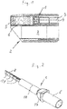
- FIG. 1 For example, the distal end of a video endoscope is shown in longitudinal section, which is equipped with an assembly 1 according to the invention.
- an objective 6 Connected to this window 5, on the proximal side, is an objective 6, which is fixedly connected to the distal end of the assembly 1, whose electrical connection cables are in the form of individual insulated wires 12 surrounded by a shielding tube in the form of an in FIG. 1 only schematically illustrated cable 7 are guided to the proximal end of the instrument.
- the module 1 is based on FIG. 2 (with lens) in averted form and FIG. 3 (without lens) shown.
- Such a module 1 is built on an elongated, highly flexible board 8, as in the FIGS. 4 to 7 is shown, in the FIGS. 5 and 6 in still planning form, in which the assembly takes place.
- the board 8 has a substantially elongated and rectangular shape. It is manufactured in thin-film technology, whereby by the layered structure the conductors within the board and in particular also the contact surfaces at the top of the board, which in FIG. 5 is visible, are formed.
- the board has a thickness of 60 .mu.m, its width is slightly narrower than that of an image-receiving sensor 9 arranged thereon, whose rear-side contacts are electrically conductively connected to the upper side of the board 8. Furthermore, at the top in the FIGS.
- board 8 is provided in the back of the sensor 9 with a reinforcing body 14 which is slightly smaller in its contour than the sensor 9 and at the same time forms a core around which the board 8 as in FIG. 7 is bent shown.
- the board is bent around a parallel to the transverse axis 15 bending line first by about 90 ° to both sides of the reinforcing body 14, follows in this area the reinforcing body 14 over its height, and then again to be bent on both sides by 90 ° and to be guided to the rear center along the reinforcing body 14.
- the board 8 is in turn bent on both sides by 90 °, such that the free board ends parallel to each other approximately adjacent to each other extend from the center of the reinforcing body 14 proximally.
- the bending points which are weakened by peripheral recesses 16 in cross section, are arranged so that the reinforcing body 14 is almost completely surrounded by the central part of the board 8 on four sides.
- the distance of the capacitors 10 to the sensor 9 is chosen so that these as in the FIGS. 4 and 7 can be seen, in the bent state of the board 8 are arranged at a distance behind the area in which the board 8 surrounds the reinforcing body 14.
- the contacts 11 are arranged, which, since the board 8 ends with their ends abutting each other after the folding operation, are then arranged on two opposite sides of the assembly 1.
- the circuit board 8 can also be designed so that it forms the line connection to the proximal end of the optical channel 4.
- FIG. 7 shown unit consisting of the bent around the reinforcing body 14 board 8, equipped with the image sensing sensor 9 and the capacitors 10 and connected to the contacts 11 cables 12, is cast in a housing 17, which includes the sensor 9 laterally, in this area is rectangular, tapers toward the proximal direction, to pass there into a cylindrical sleeve-shaped part 18.
- This housing 17 thus takes the in FIG. 4 shown assembly completely, with which it is firmly and permanently connected by a potting compound.
- the lens 6 is connected to the image receiving side of the sensor 9, so that the assembly 1 is completed, which not only has extremely small radial dimensions, but also axial, apart from the much thinner in cross-section cables 12.
- the assembly 1 thus formed can be used both for flexible and for rigid endoscopes and only insignificantly larger in its radial dimensions than the imaging sensor in the region of its active surface.
- the above-described module 1 is equipped with a sensor 9 and two capacitors 10 and a plurality of contacts 11. It understands itself that instead of the capacitors 10, if necessary, other electrical or electronic components can be arranged in this area proximal side of the reinforcing body 14, also number and arrangement of the contacts 11 can be suitably varied on the board.
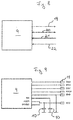
- FIG. 8 Based on FIG. 8 a block diagram for connection of the sensor 9 is shown. As can be seen, this has on the one hand to a video output 19, which includes the actual image signal, in addition to a communication port 20 and an input 21 for the clocking. Finally, a power supply 22 is present.
Landscapes
- Health & Medical Sciences (AREA)
- Life Sciences & Earth Sciences (AREA)
- Physics & Mathematics (AREA)
- Surgery (AREA)
- Engineering & Computer Science (AREA)
- Optics & Photonics (AREA)
- Radiology & Medical Imaging (AREA)
- Veterinary Medicine (AREA)
- Biophysics (AREA)
- Pathology (AREA)
- Nuclear Medicine, Radiotherapy & Molecular Imaging (AREA)
- Public Health (AREA)
- Biomedical Technology (AREA)
- Heart & Thoracic Surgery (AREA)
- Medical Informatics (AREA)
- Molecular Biology (AREA)
- Animal Behavior & Ethology (AREA)
- General Health & Medical Sciences (AREA)
- Multimedia (AREA)
- Signal Processing (AREA)
- Astronomy & Astrophysics (AREA)
- General Physics & Mathematics (AREA)
- Endoscopes (AREA)
Description
- Die Erfindung betrifft eine Baugruppe für ein Videoendoskop mit den im Oberbegriff des Anspruchs 1 angegebenen Merkmalen.
- Bei Videoendoskopen zählt es zum Stand der Technik, eine Baugruppe bestehend aus Bildsensor, Kondensator, Platine und Kabel im distalen Bereich direkt hinter dem Objektiv zu platzieren. Das durch das Objektiv erzeugte Bild wird auf den Sensor projiziert und die Signale werden über durch den Endoskopschaft hindurch geführte Kabel an die proximalseitig angeordnete Elektronik weitergeleitet. Derartige Endoskope bzw. Technoskope sind auch unter dem Begriff "Chip on the Tip-Endoskope" bekannt. Dabei gibt es unterschiedliche Bauarten, so kann der Bildsensor stehend oder liegend angeordnet sein. Auch bei Endoskopen dieser Bauart ist man stets bemüht, die Querschnittsabmessungen klein zu halten, um durch möglichst kleine Öffnungen hindurchgelangen zu können. Je kleiner jedoch der Durchmesser des Endoskopes ist, desto länger wird die Baulänge im distalen Endbereich, was insbesondere bei flexiblen Endoskopen von Nachteil ist, da die Endoskope in dem Endbereich, in dem diese Baugruppe angeordnet ist, starr, d. h. unflexibel sind. Diese Problematik stellt sich bei starren Endoskopen nicht, allerdings ist man stets bemüht, unabhängig von der Bauform nach Möglichkeit baugleiche Baugruppen verwenden zu können.
- Aus
WO 2009/041724 A1 zählt ein derartiges Videoendoskop zum Stand der Technik. Dort ist der Bildsensor quer zur Längsachse des Endoskops und auf einer flexiblen mehrfach abgebogenen Platine angeordnet. - Eine ähnliche Anordnung ist aus
US 2011/0249106 A1 bekannt. Auch dort ist der Bildsensor stehend, also quer zur Längsachse des Endoskops auf einer flexiblen Platine angeordnet, welche weitere elektronische Bauteile trägt und um ein Stützelement herum angeordnet ist. - Vor diesem Hintergrund liegt der Erfindung die Aufgabe zugrunde, eine gattungsgemäße Baugruppe für ein Videoendoskop so auszugestalten, dass einerseits eine möglichst kleine Baugröße im Bezug auf die vorgegebene Sensorgröße, also eine möglichst kleine Querschnittsab-messung und andererseits eine kurze Baulänge erreicht wird. Darüber hinaus soll eine kostengünstige Herstellung und eine Verwendung sowohl in starren als auch in flexiblen Endoskopen möglich sein.
- Diese Aufgabe wird gemäß der Erfindung durch eine Baugruppe für ein Videoendoskop mit den in Anspruch 1 angegebenen Merkmalen erreicht. Vorteilhafte Ausgestaltungen der Erfindung sind in den Unteransprüchen, der nachfolgenden Beschreibung und der Zeichnung angegeben. Dabei können gemäß der Erfindung die in den Unteransprüchen und der Beschreibung angegebenen Merkmale jeweils für sich, aber auch in geeigneter Kombination, die erfindungsgemäße Lösung gemäß Anspruch 1 weiter ausgestalten.
- Die erfindungsgemäße Baugruppe für ein Videoendoskop weist einen bildaufnehmenden Sensor auf, der elektrisch leitend auf einer flexiblen Platine angeordnet ist, welche neben dem Sensor abgebogen und proximalseitig des Sensors mit mindestens einem elektrischen Kabel leitend verbunden ist. Der Grundgedanke der vorliegenden Erfindung ist es somit, durch eine flexible Platine, wie sie typischerweise in sogenannter "Dünnschichttechnik" hergestellt wird, sowohl den Sensor als auch den oder die Kabel anzubringen, wobei die Platine die leitenden Verbindungen zwischen Sensor und Kabelanschlüssen bildet und die Kontaktierung der Platine vorteilhaft von nur einer Seite erfolgt, sodass sowohl Sensor als auch Kabelanschlüsse auf derselben Seite kontaktiert werden können, jedoch durch Abbiegen der Platine räumlich auf unterschiedlichen Ebenen befindlich sind, typischerweise die Kabelanschlüsse proximalseitig des Sensors. Hierdurch ist es möglich, eine sehr kompakt und klein bauende Baugruppe zu schaffen, die darüber hinaus kostengünstig herstellbar ist. Dabei werden die für den Sensor und die Kabel erforderlichen Kontaktflächen sowie ggf. weitere Kontaktflächen für elektronische Bauteile durch einen schichtweisen Aufbau hergestellt. Die elektrische Verschaltung ist in diesen schichtweisen Aufbau integriert, sodass die Platine mit allen notwendigen Leitern, Durchkontaktierungen, der Schaltung, der Isolation und den Lötpads eine Dicke zwischen 40 und 100 µm aufweisen kann. Dabei liegen sämtliche Kontakte nur auf einer Seite, die Kontaktierung proximalseitig des Sensors ist somit durch das Umbiegen erst möglich. Dabei kann der Aufbau der Platine auf einer planen Platte, beispielsweise einer Glasplatte schichtweise erfolgen, wobei die Bauteilbestückung vorteilhaft ebenfalls direkt auf dieser Platte erfolgt. Durch Biegen der Platine an vorteilhaft durch Markierungen gekennzeichneten Stellen kann diese sehr kompakt zusammengefaltet werden, wodurch man aus der mit dem Sensor und ggf. weiteren elektronischen Bauteilen bestückten und relativ langen Platine eine räumlich kompakte Baugruppe mit kleinstmöglichen Abmaßen erhält, und das sowohl in radialer als auch in axialer Richtung.
- Gemäß der Erfindung weist die Platine neben dem Sensor mindestens ein weiteres elektronisches Bauteil auf, welches auf einem abgebogenen Teil der Platine proximalseitig des Sensors angeordnet ist. Ein solches Bauteil ist typischerweise ein Kondensator, der in diesem proximalen Baugruppenteil erforderlich ist und vergleichsweise großen Raumbedarf hat. Dieser wird daher vorzugsweise auf der Platine neben dem Sensor angeordnet und durch Abbiegen der Platine proximalseitig des Sensors verbracht.
- Besonders vorteilhaft wird die erfindungsgemäße Baugruppe durch eine lang gestreckte schmale Platine gebildet werden, welche etwa die Breite des Sensors aufweist und zu zwei Seiten des Sensors nämlich zu zwei abgewandt gegenüberliegenden Seiten und mehrfach abgebogen ist, sodass sich ein schlanker Körper ergibt, dessen Stirnseite durch den Sensor gebildet ist.
- Um die Platine insbesondere zerstörungsfrei um 180° biegen zu können, ist gemäß der Erfindung ein Kern vorgesehen, um den die Platine herum gebogen ist, welcher in dem Bereich fluchtend zum Sensor rückseitig der Platine angeordnet ist.
- Darüber hinaus ist es zweckmäßig, die Platine im Bereich des Sensors verstärkt auszubilden. Hierzu ist gemäß der Erfindung die Platine rückseitig in dem Bereich, wo vorderseitig der Sensor angeordnet ist, durch einen Stützkörper verstärkt, der z. B. rückseitig der Platine aufgeklebt oder in anderer geeigneter Weise fixiert ist, dabei werden Stützkörper und Kern durch denselben Körper gebildet.
- Dabei ist es besonders vorteilhaft, wenn die Platine nur auf einer Platinenseite den Sensor und weitere elektronische Bauteile und Anschlüsse trägt, da dann eine besonders dünne und vorteilhaft einlagige Platine Verwendung finden kann. Erfindungsgemäß weist die Baugruppe eine vorzugsweise einlagige Flex-Platine auf, die eine Dicke zwischen 40 µm und 100 µm, beispielsweise 60 µm aufweist. Solche extrem dünnen Platinen können in besonders engen Radien abgebogen werden, und zwar auch über 90° und mehr, sodass quasi eine Faltung der Platine möglich ist, wodurch das Bauvolumen reduziert wird. Gemäß der Erfindung kann eine solche extrem dünne und flexible Platine in einem Biegeradius abgebogen sein, der dem 0,5 bis 2fachen der Platinendicke entspricht. Vorteilhaft entspricht der Biegeradius sogar nur dem 0,8 bis 1,2fachen der Platinendicke, sodass beispielsweise bei einer Platinendicke von 40 µm auch ein extrem kleiner Biegeradius von 40 µm vorgesehen sein kann.
- Um im Bereich einer Biegung die Biegespannung innerhalb der Platine zu reduzieren, ist gemäß einer vorteilhaften Weiterbildung der Erfindung mindestens eine Ausnehmung in diesem Bereich vorgesehen. Zweckmäßigerweise sind im Biegebereich mehrere nebeneinander angeordnete Ausnehmungen vorgesehen, die bevorzugt eine gerundete Kontur aufweisen und somit Kräfte kontinuierlich in die verbleibenden Stegbereiche einleiten können. Wenn im Biegebereich aufgrund der Leiterbahnen kein Raum für eine solche Ausnehmung ist, empfiehlt es sich, zumindest in den Randbereichen seitlich offene Ausnehmungen vorzusehen, sodass die Platine im Biegebereich eine geringere Breite als im übrigen Bereich aufweist.
- Gemäß einer vorteilhaften Weiterbildung der Erfindung sind die Platinenteile, die rückseitig aneinander anliegen, vorteilhaft durch Kleben miteinander verbunden, sodass insbesondere vor dem Verguss der Baugruppe eine höhere Stabilität gegeben ist.
- Eine besonders kompakte und für eine Anordnung mit stehendem Sensor vorgesehene Baugruppe ergibt sich dadurch, dass die Platine an einer Seite neben dem Sensor um etwa 180° abgebogen ist, dann sensorparallel verläuft und einen davon um etwa 90° proximalwärts abgebogenen Endabschnitt aufweist, der an dem sensorparallelen Abschnitt anschließt. Dann ergeben sich konstruktiv noch Flächen auf der Platine, die für weitere Bauteile oder Anschlüsse genutzt werden können. Ein solches weiteres Bauteil kann insbesondere ein Kondensator sein, der dann vorteilhaft im Endabschnitt auf der Platine elektrisch leitend angeordnet ist, also den Raum zwischen der Platine und der durch die 180°-Umbiegung gebildeten Seite, also den Freiraum rückseitig des Sensors jenseits der Platine nutzt.
- Vorzugsweise erfolgt die elektrische Verbindung nicht über ein gemeinsames Kabel, sondern über mehrere einadrige Kabel, die an Lötpads, die an einem oder beiden Endabschnitten der Platine angeordnet sind, elektrisch leitend angeschlossen sind. Durch das Verwenden von Einzelleitern anstelle eines kompakten und fertig konfektionierten Kabelverbundes ist es möglich, die Verbindung der elektrischen Leiter mit der Platine sehr kurz zu gestalten. Dies wird dadurch möglich, dass die Einzelleiter sehr kurz abisoliert und mit der Platine verlötet werden können, wie dies bei einem kompakten mehradrigen Kabel, bei welchem die einzelnen Leiter fest eingebunden sind, so nicht möglich ist.
- Um die Vielzahl dieser ein- oder wenigadrigen Kabel zusammenzufassen und zu bündeln, ist gemäß einer Weiterbildung der Erfindung vorgesehen, entweder nur die Kabel oder aber vorzugsweise die platinenseitigen Kabelenden und die Endabschnitte der Platine durch einen abschirmenden Schlauch zu umgeben.
- Alternativ kann die Platine auch bis zum proximalseitigen Ende des Videoendoskops geführt sein und so die Kabel in diesem Bereich ersetzen, dann erfolgt die Kontaktierung im Bereich des proximalseitigen Schaftendes. Das Objektiv wird vorteilhaft unmittelbar auf dem Sensor angebracht. Diese ganze Baugruppe, bestehend aus ggf. Objektiv, Sensor, Platine und den platinenseitigen Kabelenden mit dem abschirmenden Schlauch, wird dann in einem umgebenden Gehäuse in Kunststoff vergossen, um die Bauteile zueinander zu fixieren und gleichzeitig vor äußeren Einflüssen zu schützen.
- Die erfindungsgemäße Baugruppe ist zum Eingliedern am distalen Ende eines Endoskops mit einem starren oder flexiblen Schaft vorgesehen, wobei durch den Schaft die elektrischen Verbindungskabel geführt sind oder aber die Platine selbst die Leitungsverbindungen in diesem Bereich bildet.
- Die Erfindung ist nachfolgend anhand eines in der Zeichnung dargestellten Ausführungsbeispiels näher erläutert. Es zeigen:
- Fig. 1
- in stark vereinfachter schematischer Längsschnittdarstellung das distale Ende eines Endoskops,
- Fig. 2
- eine in einem Gehäuse eingegliederte Baugruppe mit Objektiv in perspektivischer Ansicht von vorne,
- Fig. 3
- in vergrößerter Darstellung die Baugruppe aus
Fig. 1 in ein Gehäuse eingegossen mit daran angeschlossenen Kabeln von vorne, - Fig. 4
- die Baugruppe ohne Gehäuse in perspektivischer Ansicht von hinten,
- Fig. 5
- eine Draufsicht auf die bestückte Platine von der Sensorseite,
- Fig. 6
- eine Seitenansicht der bestückten Platine,
- Fig. 7
- die bestückte Platine in abgebogener Form,
- Fig. 8
- ein Blockschaltbild der Baugruppe und
- Fig. 9
- einen Stromlaufplan der Baugruppe.
- In
Figur 1 ist beispielhaft das distale Ende eines Videoendoskops im Längsschnitt dargestellt, welches mit einer erfindungsgemäßen Baugruppe 1 ausgestattet ist. In der Figur zu sehen ist der distale Endabschnitt 2 mit einem Arbeitskanal 3 und einem Optikkanal 4, der endseitig durch ein fest und dicht den Kanal abschließendes Fenster 5, z. B. aus Saphir, abgeschlossen wird. An dieses Fenster 5 schließt sich proximalseitig ein Objektiv 6, welches fest mit dem distalen Ende der Baugruppe 1 verbunden ist, deren elektrische Anschlusskabel in Form von einzelnen isolierten und von einem abschirmenden Schlauch umgebenen Drähten 12 in Form eines inFigur 1 nur schematisch dargestellten Kabels 7 zum proximalen Instrumentenende geführt sind. - Die Baugruppe 1 ist anhand von
Figur 2 (mit Objektiv) in abgewandter Form undFigur 3 (ohne Objektiv) dargestellt. - Aufgebaut ist eine solche Baugruppe 1 auf einer lang gestreckten, hochflexiblen Platine 8, wie sie in den
Figuren 4 - 7 dargestellt ist, und zwar in denFiguren 5 und 6 in noch planer Form, in welcher die Bestückung erfolgt. Die Platine 8 hat eine im Wesentlichen lang gestreckte und rechteckige Form. Sie ist in Dünnschichttechnik gefertigt, wobei durch den schichtweisen Aufbau die Leiter innerhalb der Platine und insbesondere auch die Kontaktflächen an der Oberseite der Platine, die inFigur 5 sichtbar ist, gebildet sind. Im vorliegenden Ausführungsbeispiel weist die Platine eine Dicke von 60 µm auf, ihre Breite ist geringfügig schmaler als die eines darauf angeordneten bildaufnehmenden Sensors 9, dessen rückseitige Kontakte mit der Oberseite der Platine 8 elektrisch leitend verbunden sind. Weiterhin sind an der Oberseite in denFiguren 5 und 6 mit Abstand rechts und links zum Sensor 9 Kondensatoren 10 auf der Oberseite der Platine 8 angeordnet und elektrisch leitend mit dieser verbunden. Schließlich sind an der Oberseite der Platine 8 elektrische Kontakte 11 vorgesehen, an denen einadrige elektrisch isolierte Kabel 12 ebenfalls durch Löten angeschlossen werden, über welche die Baugruppe 1 elektrisch leitend mit einer proximalseitig angeordneten (nicht dargestellten) Steuer- und Auswerteinheit verbunden ist. - Die Kondensatoren 10, die mit Abstand und parallel zum Sensor 9 auf der Oberseite der Platine 8 angeordnet sind, erstrecken sich also quer zur Längsrichtung 13 der Platine 8.
- Diese anhand der
Figuren 5 und 6 dargestellte und fertig bestückte Platine 8 wird im Bereich des Sensors 9 rückseitig mit einem Verstärkungskörper 14 versehen, der in seiner Kontur geringfügig kleiner als der Sensor 9 ist und gleichzeitig einen Kern bildet, um welchen die Platine 8 wie inFigur 7 dargestellt abgebogen wird. Die Platine wird dabei um eine parallel zur Querachse 15 angeordnete Biegelinie zunächst um etwa 90° zu beiden Seiten des Verstärkungskörpers 14 abgebogen, folgt in diesem Bereich dem Verstärkungskörper 14 über seine Höhe, um dann nochmals zu beiden Seiten jeweils um 90° abgebogen zu werden und bis zur rückseitigen Mitte längs des Verstärkungskörpers 14 geführt zu werden. Dort ist die Platine 8 wiederum zu beiden Seiten um 90° abgebogen, derart, dass die freien Platinenenden parallel zueinander etwa aneinander anliegend sich von der Mitte des Verstärkungskörpers 14 proximalwärts erstrecken. - Die Biegestellen, die durch randseitige Ausnehmungen 16 im Querschnitt geschwächt sind, sind so angeordnet, dass der Verstärkungskörper 14 von dem mittleren Teil der Platine 8 an vier Seiten nahezu vollständig umgeben wird. Dabei ist der Abstand der Kondensatoren 10 zum Sensor 9 so gewählt, dass diese wie in den
Figuren 4 und7 erkennbar, in gebogenem Zustand der Platine 8 mit Abstand hinter dem Bereich angeordnet sind, in welchem die Platine 8 den Verstärkungskörper 14 umgibt. Am Ende der Platine 8 sind die Kontakte 11 angeordnet, die, da die Platine 8 mit ihren Enden aneinander liegend nach dem Faltvorgang ausläuft, dann auf zwei gegenüber liegend abgewandten Seiten der Baugruppe 1 angeordnet sind. - Dabei können die Kabel 7 wie vorbeschrieben und anhand von
Figur 3 dargestellt, an den Kontakten 11 angelötet sein. Es kann jedoch auch vorgesehen sein, die Platine so auszugestalten, wie dies anhand vonFigur 2 dargestellt ist, d. h., dass alle Kontakte in Längsrichtung der Baugruppe 1 gesehen hintereinander liegen. Die Platine 8 kann auch so ausgebildet sein, dass sie die Leitungsverbindung bis zum proximalen Ende des Optikkanals 4 bildet. - Die anhand von
Figur 7 dargestellte Einheit bestehend aus der um den Verstärkungskörper 14 gebogenen Platine 8, bestückt mit dem bildaufnehmenden Sensor 9 sowie den Kondensatoren 10 und den an den Kontakten 11 angeschlossenen Kabeln 12, ist in einem Gehäuse 17 eingegossen, welches den Sensor 9 seitlich umfasst, in diesem Bereich rechteckig ausgebildet ist, verjüngend nach proximalwärts zuläuft, um dort in einen zylindrischen hülsenförmigen Teil 18 überzugehen. Dieses Gehäuse 17 nimmt also die inFigur 4 dargestellte Baueinheit vollständig auf, mit der es durch eine Vergussmasse fest und unlösbar verbunden ist. Schließlich wird das Objektiv 6 mit der bildaufnehmenden Seite des Sensors 9 verbunden, sodass die Baugruppe 1 fertiggestellt ist, welche nicht nur extrem kleine radiale Abmessungen aufweist, sondern auch axiale, wenn man einmal von den im Querschnitt deutlich dünneren Kabeln 12 absieht. Die so gebildete Baugruppe 1 ist sowohl für flexible als auch für starre Endoskope einsetzbar und in ihren radialen Abmessungen nur unwesentlich größer als der bildgebende Sensor im Bereich seiner aktiven Oberfläche. - Die vorbeschriebene Baugruppe 1 ist mit einem Sensor 9 und zwei Kondensatoren 10 sowie einer Vielzahl von Kontakten 11 bestückt. Es versteht sich, dass statt der Kondensatoren 10 ggf. auch andere elektrische oder elektronische Bauteile in diesem Bereich proximalseitig des Verstärkungskörpers 14 angeordnet sein können, auch können Anzahl und Anordnung der Kontakte 11 auf der Platine geeignet variiert werden.
- Anhand von
Figur 8 ist ein Blockschaltbild zum Anschluss des Sensors 9 dargestellt. Wie daraus ersichtlich ist, weist dieser zum einen einen Videoausgang 19 auf, welcher das eigentliche Bildsignal beinhaltet, darüber hinaus einen Kommunikationsport 20 sowie einen Eingang 21 für die Taktung. Schließlich ist eine Spannungsversorgung 22 vorhanden. - In Stromlaufbahn gemäß
Figur 9 sind die Anschlüsse des Sensors 9 im Einzelnen aufgeführt, hierin bedeuten: - Vout
- - Videoausgangssignal
- SIOC SIOD
- Kommunikationskanal

- XVCLK
- - Taktung
- GND
- - Spannungsversorgung
- VDD
- - Spannungsversorgung
- VN
- - Spannungsversorgung
- AVDD
- - Spannungsversorgung
- DOVDD
- - Spannungsversorgung
- In Stromlaufbahn gemäß
Figur 9 sind die beiden Kondensatoren 10 deutlich sichtbar, die hier eine Kapazität von jeweils 100 nF aufweisen. -
- 1
- - Baugruppe
- 2
- - distaler Endabschnitt
- 3
- - Arbeitskanal
- 4
- - Optikkanal
- 5
- - Fenster
- 6
- - Objektiv
- 7
- - Kabel
- 8
- - Platine
- 8'
- - Platine
- 9
- - Sensor
- 10
- - Kondensator
- 11
- - Kontakte
- 12
- - einadrige Kabel
- 13
- - Längsrichtung
- 14
- - Verstärkungskörper
- 15
- - Querachse
- 16
- - Ausnehmungen
- 17
- - Gehäuse
- 18
- - hülsenförmiger Teil von 17
- 19
- - Videoausgang
- 20
- - Kommunikationsport
- 21
- - Taktung
- 22
- - Spannungsversorgung
Claims (12)
- Baugruppe für ein Videoendoskop mit einem bildaufnehmenden Sensor (9), der auf einer flexiblen Platine (8) elektrisch leitend angeordnet ist, die neben dem Sensor (9) mindestens an einer Seite abgebogen und proximalseitig des Sensors (9) mit mindestens einem elektrischen Kabel (7) leitend verbunden ist, dadurch gekennzeichnet, dass die Platine (8) neben dem Sensor (9) mindestens ein weiteres elektronisches Bauteil (10) trägt, welches auf dem abgebogenen Teil der Platine (8) proximalseitig des Sensors (9) angeordnet ist, dass die Platine (8) rückseitig des Sensors (9) mit einem Verstärkungskörper (14) versehen ist, der einen Kern bildet, um welchen die Platine (8) zunächst um etwa 90° zu beiden Seiten des Verstärkungskörpers (14) abgebogen ist, in diesem Bereich dem Verstärkungskörper (14) über seine Höhe folgt, dann nochmals zu beiden Seiten jeweils um 90° abgebogen und bis zur rückseitigen Mitte längs des Verstärkungskörpers (14) geführt und dort wiederum zu beiden Seiten um 90° derart abgebogen ist, dass die freien Platinenenden parallel zueinander anliegend sich von der Mitte des Verstärkungskörpers (14) proximalwärts erstrecken und das mindestens eine weitere elektronische Bauteil (10) tragen.
- Baugruppe nach Anspruch 1, dadurch gekennzeichnet, dass beide Endabschnitte ein weiteres elektronisches Bauteil (10) tragen.
- Baugruppe nach Anspruch 2, dadurch gekennzeichnet, dass beide Endabschnitte jeweils einen Kondensator (10) tragen.
- Baugruppe nach einem der vorhergehenden Ansprüche, dadurch gekennzeichnet, dass die Endabschnitte der Platine (8) an ihren Endabschnitten Kontakte (11) aufweisen, an denen die Kabel (12) angeschlossen sind.
- Baugruppe nach einem der vorhergehenden Ansprüche, dadurch gekennzeichnet, dass die Platine (8) eine vorzugsweise einlagige Flex-Platine mit einer Dicke zwischen 40 µm und 100 µm ist.
- Baugruppe nach einem der vorhergehenden Ansprüche, dadurch gekennzeichnet, dass die Platine (8) in einem Biegeradius abgebogen ist, der dem 0,5 bis 2-fachen, vorzugsweise dem 0,8 bis 1,2-fachen der Platinendicke entspricht.
- Baugruppe nach einem der vorhergehenden Ansprüche, dadurch gekennzeichnet, dass die Platine (8) im Bereich einer Biegung mit mindestens einer Ausnehmung (24) zur Reduzierung der Biegespannung versehen ist.
- Baugruppe nach einem der vorhergehenden Ansprüche, dadurch gekennzeichnet, dass die Platine (8) über einadrige Kabel (12) angeschlossen ist.
- Baugruppe nach einem der vorhergehenden Ansprüche, dadurch gekennzeichnet, dass die platinenseitigen Kabelenden und die Endabschnitte der Platine (8) durch einen abschirmenden Schlauch umgeben sind.
- Baugruppe nach einem der vorhergehenden Ansprüche, dadurch gekennzeichnet, dass der Sensor (9) umfang- und platinenseitig die Platine (8) und die platinenseitigen Kabelenden mit dem abschirmenden Schlauch, vorzugsweise in einem umgebenden Gehäuse (17) in Kunststoff vergossen sind.
- Baueinheit nach einem der vorhergehenden Ansprüche, dadurch gekennzeichnet, dass sie aus der um einen Verstärkungskörper (14) gebogenen Platine (8), bestückt mit dem bildaufnehmenden Sensor (9) sowie den Kondensatoren (10) und den an den Kontakten (11) angeschlossenen Kabeln (12) besteht und in einem Gehäuse (17) eingegossen ist, welches den Sensor (9) seitlich umfasst, in diesem Bereich rechteckig ausgebildet ist, verjüngend nach proximalwärts zuläuft, um dort in einen zylindrischen hülsenförmigen Teil (18) überzugehen.
- Endoskop mit einem starren oder flexiblen Schaft mit einer Baugruppe (1) nach einem der vorhergehenden Ansprüche, dadurch gekennzeichnet, dass die Baugruppe (1) in einem distalen Abschnitt (2) des Schaftes angeordnet und die Kabel (12) durch den Schaft zum proximalen Ende geführt sind.
Applications Claiming Priority (3)
| Application Number | Priority Date | Filing Date | Title |
|---|---|---|---|
| DE102013202516 | 2013-02-15 | ||
| EP14704359.0A EP2957098A1 (de) | 2013-02-15 | 2014-02-14 | Baugruppe für ein video-endoskop |
| PCT/EP2014/052914 WO2014125070A1 (de) | 2013-02-15 | 2014-02-14 | Baugruppe für ein videoendoskop |
Related Parent Applications (1)
| Application Number | Title | Priority Date | Filing Date |
|---|---|---|---|
| EP14704359.0A Division EP2957098A1 (de) | 2013-02-15 | 2014-02-14 | Baugruppe für ein video-endoskop |
Publications (2)
| Publication Number | Publication Date |
|---|---|
| EP3206386A1 EP3206386A1 (de) | 2017-08-16 |
| EP3206386B1 true EP3206386B1 (de) | 2018-11-21 |
Family
ID=50101907
Family Applications (2)
| Application Number | Title | Priority Date | Filing Date |
|---|---|---|---|
| EP17163342.3A Active EP3206386B1 (de) | 2013-02-15 | 2014-02-14 | Baugruppe für ein videoendoskop |
| EP14704359.0A Withdrawn EP2957098A1 (de) | 2013-02-15 | 2014-02-14 | Baugruppe für ein video-endoskop |
Family Applications After (1)
| Application Number | Title | Priority Date | Filing Date |
|---|---|---|---|
| EP14704359.0A Withdrawn EP2957098A1 (de) | 2013-02-15 | 2014-02-14 | Baugruppe für ein video-endoskop |
Country Status (4)
| Country | Link |
|---|---|
| US (1) | US10025088B2 (de) |
| EP (2) | EP3206386B1 (de) |
| CN (1) | CN104995907B (de) |
| WO (1) | WO2014125070A1 (de) |
Families Citing this family (35)
| Publication number | Priority date | Publication date | Assignee | Title |
|---|---|---|---|---|
| US9901244B2 (en) * | 2009-06-18 | 2018-02-27 | Endochoice, Inc. | Circuit board assembly of a multiple viewing elements endoscope |
| US12220105B2 (en) * | 2010-06-16 | 2025-02-11 | Endochoice, Inc. | Circuit board assembly of a multiple viewing elements endoscope |
| JP5806343B2 (ja) | 2014-01-16 | 2015-11-10 | ソニー・オリンパスメディカルソリューションズ株式会社 | 光電複合モジュール、カメラヘッド、及び内視鏡装置 |
| US10348941B2 (en) * | 2014-07-30 | 2019-07-09 | Karl Storz Endovision, Inc. | Durable flexible circuit assembly |
| DE102015204884B3 (de) * | 2015-03-18 | 2016-07-21 | Olympus Winter & Ibe Gmbh | Elektrisches Verbindungsstück für ein Endoskop und Verfahren zum Herstellen einer elektrischen Verbindung in einem Endoskop |
| JP6539548B2 (ja) * | 2015-08-31 | 2019-07-03 | 富士フイルム株式会社 | 内視鏡用撮像装置及び内視鏡 |
| EP4541257A3 (de) * | 2015-09-01 | 2025-10-01 | DEKA Products Limited Partnership | Endoskop mit schwenkbarer kamera und zugehöriges verfahren |
| TWM519485U (zh) * | 2016-01-14 | 2016-04-01 | Dex Medical Device Co Ltd | 微型觀察鏡攝像鏡頭之改良結構(一) |
| JP6605632B2 (ja) * | 2016-02-18 | 2019-11-13 | オリンパス株式会社 | 撮像装置および内視鏡 |
| JP6322348B1 (ja) * | 2016-06-07 | 2018-05-09 | オリンパス株式会社 | 撮像ユニット |
| EP3418694B1 (de) * | 2017-06-21 | 2020-01-01 | Optosys SA | Näherungssensor |
| JP6641329B2 (ja) * | 2017-08-31 | 2020-02-05 | 株式会社フジクラ | 撮像モジュール付きカテーテル |
| JP6641330B2 (ja) * | 2017-08-31 | 2020-02-05 | 株式会社フジクラ | 撮像モジュール付きカテーテル |
| CN111031881B (zh) * | 2017-08-31 | 2022-08-16 | 富士胶片株式会社 | 内窥镜的连接器装置 |
| JP6637933B2 (ja) * | 2017-08-31 | 2020-01-29 | 株式会社フジクラ | 撮像モジュール |
| JP6898874B2 (ja) * | 2018-02-13 | 2021-07-07 | 富士フイルム株式会社 | 内視鏡撮像装置及び内視鏡 |
| JP6697021B2 (ja) * | 2018-04-03 | 2020-05-20 | 株式会社フジクラ | 内視鏡 |
| JP7132007B2 (ja) * | 2018-07-18 | 2022-09-06 | i-PRO株式会社 | 内視鏡用撮像ユニットおよび内視鏡 |
| DE102018132449B4 (de) * | 2018-12-17 | 2025-01-16 | Schölly Fiberoptic GmbH | Untersuchungsinstrument |
| CN109700432B (zh) * | 2018-12-21 | 2024-06-07 | 上海英诺伟医疗器械股份有限公司 | 基于柔性管的探测封装结构与体内探测装置 |
| DE102019103288A1 (de) * | 2019-02-11 | 2020-08-13 | Olympus Winter & Ibe Gmbh | Elektronische Vorrichtung für ein Endoskop und Endoskop |
| US11583171B2 (en) | 2019-08-22 | 2023-02-21 | Omnivision Technologies, Inc. | Surface-mount device platform and assembly |
| US11938662B2 (en) | 2019-09-06 | 2024-03-26 | Ambu A/S | Tip part assembly for an endoscope |
| TWM602016U (zh) * | 2020-05-11 | 2020-10-01 | 榮晶生物科技股份有限公司 | 內視鏡裝置及插管部 |
| CN111614883A (zh) * | 2020-06-27 | 2020-09-01 | 深圳华视内窥镜有限公司 | 一种双摄像头内窥镜 |
| EP4216791A1 (de) | 2020-09-22 | 2023-08-02 | Ambu A/S | Medizinische vorrichtung mit einem schlauch |
| DE102021106836A1 (de) * | 2020-10-02 | 2022-04-07 | Karl Storz Se & Co. Kg | Optisches Filtersystem für ein Video-Endoskop, Anzeigesystem und Video-Endoskop |
| US11642016B2 (en) * | 2021-08-10 | 2023-05-09 | Altek Biotechnology Corporation | Image capturing module, endoscope and method of manufacturing image capturing module |
| US11759095B2 (en) * | 2021-08-29 | 2023-09-19 | Altek Biotechnology Corporation | Image capturing assembly and related endoscope |
| US12551094B2 (en) | 2021-11-26 | 2026-02-17 | Altek Biotechnology Corporation | Endoscopic image capturing assembly and endoscopic device therewith |
| US11963667B2 (en) * | 2021-11-26 | 2024-04-23 | Altek Biotechnology Corporation | Endoscopic image capturing assembly and endoscopic device therewith |
| US20240023795A1 (en) * | 2022-07-19 | 2024-01-25 | Boston Scientific Scimed, Inc. | Medical device assemblies and components |
| FR3139987A1 (fr) * | 2022-09-28 | 2024-03-29 | Axess Vision Technology | Système endoscopique médical présentant une insensibilité aux ondes électromagnétiques |
| CN116746862A (zh) * | 2023-06-16 | 2023-09-15 | 广州瑞派医疗器械有限责任公司 | 成像模组及内窥镜 |
| US12556795B2 (en) | 2023-09-01 | 2026-02-17 | Covidien Lp | Folding printed circuit board assembly for endoscope camera |
Family Cites Families (12)
| Publication number | Priority date | Publication date | Assignee | Title |
|---|---|---|---|---|
| JPS56144673A (en) * | 1980-04-11 | 1981-11-11 | Hitachi Denshi Ltd | Telecamera |
| US6635865B1 (en) | 2000-07-25 | 2003-10-21 | Andrew J. Soltyk | Imaging sensor microassembly having dual circuit board formed of unsymmetrical T shape |
| JP3684365B2 (ja) * | 2003-02-21 | 2005-08-17 | フジノン株式会社 | 立体電子内視鏡用撮像装置 |
| US7075794B2 (en) * | 2003-09-11 | 2006-07-11 | Motorola, Inc. | Electronic control unit |
| JP4981316B2 (ja) | 2005-12-16 | 2012-07-18 | オリンパスメディカルシステムズ株式会社 | 被検体内導入装置 |
| JP2009082503A (ja) | 2007-09-28 | 2009-04-23 | Fujifilm Corp | 撮像装置及びその撮像装置を備えた内視鏡 |
| CN101313871B (zh) * | 2008-03-26 | 2012-04-18 | 东莞光阵显示器制品有限公司 | 一种cmos模组及其在医疗器械领域内的应用 |
| US8698887B2 (en) * | 2010-04-07 | 2014-04-15 | Olympus Corporation | Image pickup apparatus, endoscope and manufacturing method for image pickup apparatus |
| JP5675151B2 (ja) | 2010-04-07 | 2015-02-25 | オリンパス株式会社 | 撮像装置、電子内視鏡および撮像装置の製造方法 |
| JP5735105B2 (ja) * | 2011-05-25 | 2015-06-17 | オリンパス株式会社 | 内視鏡装置 |
| US9380928B2 (en) | 2011-06-06 | 2016-07-05 | Fujikura Ltd. | Structure of imaging part in electronic visualized catheter |
| JP5912058B2 (ja) * | 2012-03-30 | 2016-04-27 | 株式会社フジクラ | 撮像モジュール、レンズ付き撮像モジュール、内視鏡、撮像モジュールの製造方法、フレキシブル配線基板成形装置 |
-
2014
- 2014-02-14 CN CN201480008849.1A patent/CN104995907B/zh active Active
- 2014-02-14 EP EP17163342.3A patent/EP3206386B1/de active Active
- 2014-02-14 US US14/768,059 patent/US10025088B2/en active Active
- 2014-02-14 WO PCT/EP2014/052914 patent/WO2014125070A1/de not_active Ceased
- 2014-02-14 EP EP14704359.0A patent/EP2957098A1/de not_active Withdrawn
Non-Patent Citations (1)
| Title |
|---|
| None * |
Also Published As
| Publication number | Publication date |
|---|---|
| WO2014125070A1 (de) | 2014-08-21 |
| US20150378144A1 (en) | 2015-12-31 |
| US10025088B2 (en) | 2018-07-17 |
| EP2957098A1 (de) | 2015-12-23 |
| CN104995907B (zh) | 2019-05-28 |
| EP3206386A1 (de) | 2017-08-16 |
| CN104995907A (zh) | 2015-10-21 |
Similar Documents
| Publication | Publication Date | Title |
|---|---|---|
| EP2957098A1 (de) | Baugruppe für ein video-endoskop | |
| EP1659780B1 (de) | Bildaufnehmermodul sowie Verfahren zum Zusammenbauen eines Bildaufnehmermoduls | |
| EP1182959B1 (de) | Bildaufnehmermodul sowie verfahren zum zusammenbauen eines derartigen bildaufnehmermoduls | |
| DE4129961C2 (de) | Videoendoskop mit Festkörperbildaufnahmevorrichtung | |
| DE19936300B4 (de) | Druckerkennungsvorrichtung und Druckerkennungsvorrichtung-Anordnung hiermit | |
| EP2018043B1 (de) | Bildaufnehmermodul | |
| DE3715417A1 (de) | Halbleiter-bilderzeugungsvorrichtung, sowie hiermit ausgestattetes endoskop | |
| EP2434748A1 (de) | Bildaufnehmermodul sowie Verfahren zur Herstellung eines Bildaufnehmermoduls | |
| DE19940695B4 (de) | Elektronisches Mediagerät | |
| EP2728982A1 (de) | Leiterplattenbaugruppe für ein Steuergerät, Steuergerät für ein Kraftfahrzeug und Signalverarbeitungsanordnung | |
| DE202009017933U1 (de) | Mehrfach-Koaxialkabel-Steckverbindung | |
| EP2979333B1 (de) | Steckverbinder mit übersprechkompensation | |
| EP3080872B1 (de) | Kontaktanbindung von geschirmten datenleitungen an einer platine sowie verfahren zur kontaktierung mehrerer geschirmter datenleitungen an einer platine | |
| EP2503860A1 (de) | Flexibles Verbindungskabel zur elektrischen Verbindung eines Messwertaufnehmers und einer Auswerteelektronik einer Messbaugruppe | |
| DE102013000785B4 (de) | Radarvorrichtung und verfahren zur herstellung derselben | |
| DE2521072A1 (de) | Organ zur verbindung des endes eines leiters mit einem stift | |
| DE102009046870A1 (de) | Elektronisches Schaltgerät mit Anschlusskabel | |
| DE102012012528A1 (de) | Messvorrichtung zum Bestimmen einer Prozessgröße | |
| EP3881750B1 (de) | Steckverbindung für ein videoendoskop, videoendoskop und verfahren zur herstellung einer steckverbindung | |
| DE102012204069B4 (de) | Elektrische Steckerverbindung | |
| DE102011119841B4 (de) | Elektronikeinheit, Verfahren zur Herstellung einer Elektronikeinheit und elektronisches Messgerät mit einer Elektronikeinheit | |
| WO1990000316A1 (de) | Mikrowellenschalteranordnung | |
| DE202013010545U1 (de) | Elektrisches Kontaktelement | |
| DE102023112524A1 (de) | Anordnung zum Schutz elektrischer Anschlüsse einer elektrischen Übertragungsleitung innerhalb eines Schafts eines Endoskops und ein Endoskop | |
| DE102012201753A1 (de) | Kondensator sowie Verfahren zur Herstellung eines Kondensators |
Legal Events
| Date | Code | Title | Description |
|---|---|---|---|
| PUAI | Public reference made under article 153(3) epc to a published international application that has entered the european phase |
Free format text: ORIGINAL CODE: 0009012 |
|
| STAA | Information on the status of an ep patent application or granted ep patent |
Free format text: STATUS: THE APPLICATION HAS BEEN PUBLISHED |
|
| AC | Divisional application: reference to earlier application |
Ref document number: 2957098 Country of ref document: EP Kind code of ref document: P |
|
| AK | Designated contracting states |
Kind code of ref document: A1 Designated state(s): AL AT BE BG CH CY CZ DE DK EE ES FI FR GB GR HR HU IE IS IT LI LT LU LV MC MK MT NL NO PL PT RO RS SE SI SK SM TR |
|
| STAA | Information on the status of an ep patent application or granted ep patent |
Free format text: STATUS: REQUEST FOR EXAMINATION WAS MADE |
|
| 17P | Request for examination filed |
Effective date: 20180214 |
|
| RBV | Designated contracting states (corrected) |
Designated state(s): AL AT BE BG CH CY CZ DE DK EE ES FI FR GB GR HR HU IE IS IT LI LT LU LV MC MK MT NL NO PL PT RO RS SE SI SK SM TR |
|
| GRAP | Despatch of communication of intention to grant a patent |
Free format text: ORIGINAL CODE: EPIDOSNIGR1 |
|
| STAA | Information on the status of an ep patent application or granted ep patent |
Free format text: STATUS: GRANT OF PATENT IS INTENDED |
|
| RIC1 | Information provided on ipc code assigned before grant |
Ipc: A61B 1/04 20060101ALI20180605BHEP Ipc: A61B 1/05 20060101ALI20180605BHEP Ipc: A61B 1/00 20060101ALI20180605BHEP Ipc: H04N 5/225 20060101AFI20180605BHEP Ipc: G02B 23/24 20060101ALI20180605BHEP Ipc: A61B 1/005 20060101ALI20180605BHEP Ipc: H01L 27/146 20060101ALI20180605BHEP |
|
| INTG | Intention to grant announced |
Effective date: 20180621 |
|
| GRAS | Grant fee paid |
Free format text: ORIGINAL CODE: EPIDOSNIGR3 |
|
| GRAA | (expected) grant |
Free format text: ORIGINAL CODE: 0009210 |
|
| STAA | Information on the status of an ep patent application or granted ep patent |
Free format text: STATUS: THE PATENT HAS BEEN GRANTED |
|
| AC | Divisional application: reference to earlier application |
Ref document number: 2957098 Country of ref document: EP Kind code of ref document: P |
|
| AK | Designated contracting states |
Kind code of ref document: B1 Designated state(s): AL AT BE BG CH CY CZ DE DK EE ES FI FR GB GR HR HU IE IS IT LI LT LU LV MC MK MT NL NO PL PT RO RS SE SI SK SM TR |
|
| REG | Reference to a national code |
Ref country code: CH Ref legal event code: EP |
|
| REG | Reference to a national code |
Ref country code: IE Ref legal event code: FG4D Free format text: LANGUAGE OF EP DOCUMENT: GERMAN |
|
| REG | Reference to a national code |
Ref country code: AT Ref legal event code: REF Ref document number: 1068940 Country of ref document: AT Kind code of ref document: T Effective date: 20181215 |
|
| REG | Reference to a national code |
Ref country code: DE Ref legal event code: R096 Ref document number: 502014010176 Country of ref document: DE |
|
| REG | Reference to a national code |
Ref country code: NL Ref legal event code: MP Effective date: 20181121 |
|
| PG25 | Lapsed in a contracting state [announced via postgrant information from national office to epo] |
Ref country code: LV Free format text: LAPSE BECAUSE OF FAILURE TO SUBMIT A TRANSLATION OF THE DESCRIPTION OR TO PAY THE FEE WITHIN THE PRESCRIBED TIME-LIMIT Effective date: 20181121 Ref country code: FI Free format text: LAPSE BECAUSE OF FAILURE TO SUBMIT A TRANSLATION OF THE DESCRIPTION OR TO PAY THE FEE WITHIN THE PRESCRIBED TIME-LIMIT Effective date: 20181121 Ref country code: NO Free format text: LAPSE BECAUSE OF FAILURE TO SUBMIT A TRANSLATION OF THE DESCRIPTION OR TO PAY THE FEE WITHIN THE PRESCRIBED TIME-LIMIT Effective date: 20190221 Ref country code: BG Free format text: LAPSE BECAUSE OF FAILURE TO SUBMIT A TRANSLATION OF THE DESCRIPTION OR TO PAY THE FEE WITHIN THE PRESCRIBED TIME-LIMIT Effective date: 20190221 Ref country code: IS Free format text: LAPSE BECAUSE OF FAILURE TO SUBMIT A TRANSLATION OF THE DESCRIPTION OR TO PAY THE FEE WITHIN THE PRESCRIBED TIME-LIMIT Effective date: 20190321 Ref country code: HR Free format text: LAPSE BECAUSE OF FAILURE TO SUBMIT A TRANSLATION OF THE DESCRIPTION OR TO PAY THE FEE WITHIN THE PRESCRIBED TIME-LIMIT Effective date: 20181121 Ref country code: ES Free format text: LAPSE BECAUSE OF FAILURE TO SUBMIT A TRANSLATION OF THE DESCRIPTION OR TO PAY THE FEE WITHIN THE PRESCRIBED TIME-LIMIT Effective date: 20181121 Ref country code: LT Free format text: LAPSE BECAUSE OF FAILURE TO SUBMIT A TRANSLATION OF THE DESCRIPTION OR TO PAY THE FEE WITHIN THE PRESCRIBED TIME-LIMIT Effective date: 20181121 |
|
| PG25 | Lapsed in a contracting state [announced via postgrant information from national office to epo] |
Ref country code: NL Free format text: LAPSE BECAUSE OF FAILURE TO SUBMIT A TRANSLATION OF THE DESCRIPTION OR TO PAY THE FEE WITHIN THE PRESCRIBED TIME-LIMIT Effective date: 20181121 Ref country code: SE Free format text: LAPSE BECAUSE OF FAILURE TO SUBMIT A TRANSLATION OF THE DESCRIPTION OR TO PAY THE FEE WITHIN THE PRESCRIBED TIME-LIMIT Effective date: 20181121 Ref country code: GR Free format text: LAPSE BECAUSE OF FAILURE TO SUBMIT A TRANSLATION OF THE DESCRIPTION OR TO PAY THE FEE WITHIN THE PRESCRIBED TIME-LIMIT Effective date: 20190222 Ref country code: PT Free format text: LAPSE BECAUSE OF FAILURE TO SUBMIT A TRANSLATION OF THE DESCRIPTION OR TO PAY THE FEE WITHIN THE PRESCRIBED TIME-LIMIT Effective date: 20190321 Ref country code: AL Free format text: LAPSE BECAUSE OF FAILURE TO SUBMIT A TRANSLATION OF THE DESCRIPTION OR TO PAY THE FEE WITHIN THE PRESCRIBED TIME-LIMIT Effective date: 20181121 Ref country code: RS Free format text: LAPSE BECAUSE OF FAILURE TO SUBMIT A TRANSLATION OF THE DESCRIPTION OR TO PAY THE FEE WITHIN THE PRESCRIBED TIME-LIMIT Effective date: 20181121 |
|
| PG25 | Lapsed in a contracting state [announced via postgrant information from national office to epo] |
Ref country code: CZ Free format text: LAPSE BECAUSE OF FAILURE TO SUBMIT A TRANSLATION OF THE DESCRIPTION OR TO PAY THE FEE WITHIN THE PRESCRIBED TIME-LIMIT Effective date: 20181121 Ref country code: PL Free format text: LAPSE BECAUSE OF FAILURE TO SUBMIT A TRANSLATION OF THE DESCRIPTION OR TO PAY THE FEE WITHIN THE PRESCRIBED TIME-LIMIT Effective date: 20181121 Ref country code: DK Free format text: LAPSE BECAUSE OF FAILURE TO SUBMIT A TRANSLATION OF THE DESCRIPTION OR TO PAY THE FEE WITHIN THE PRESCRIBED TIME-LIMIT Effective date: 20181121 Ref country code: IT Free format text: LAPSE BECAUSE OF FAILURE TO SUBMIT A TRANSLATION OF THE DESCRIPTION OR TO PAY THE FEE WITHIN THE PRESCRIBED TIME-LIMIT Effective date: 20181121 |
|
| REG | Reference to a national code |
Ref country code: DE Ref legal event code: R097 Ref document number: 502014010176 Country of ref document: DE |
|
| PG25 | Lapsed in a contracting state [announced via postgrant information from national office to epo] |
Ref country code: SK Free format text: LAPSE BECAUSE OF FAILURE TO SUBMIT A TRANSLATION OF THE DESCRIPTION OR TO PAY THE FEE WITHIN THE PRESCRIBED TIME-LIMIT Effective date: 20181121 Ref country code: RO Free format text: LAPSE BECAUSE OF FAILURE TO SUBMIT A TRANSLATION OF THE DESCRIPTION OR TO PAY THE FEE WITHIN THE PRESCRIBED TIME-LIMIT Effective date: 20181121 Ref country code: EE Free format text: LAPSE BECAUSE OF FAILURE TO SUBMIT A TRANSLATION OF THE DESCRIPTION OR TO PAY THE FEE WITHIN THE PRESCRIBED TIME-LIMIT Effective date: 20181121 Ref country code: SM Free format text: LAPSE BECAUSE OF FAILURE TO SUBMIT A TRANSLATION OF THE DESCRIPTION OR TO PAY THE FEE WITHIN THE PRESCRIBED TIME-LIMIT Effective date: 20181121 |
|
| PLBE | No opposition filed within time limit |
Free format text: ORIGINAL CODE: 0009261 |
|
| STAA | Information on the status of an ep patent application or granted ep patent |
Free format text: STATUS: NO OPPOSITION FILED WITHIN TIME LIMIT |
|
| REG | Reference to a national code |
Ref country code: CH Ref legal event code: PL |
|
| 26N | No opposition filed |
Effective date: 20190822 |
|
| PG25 | Lapsed in a contracting state [announced via postgrant information from national office to epo] |
Ref country code: SI Free format text: LAPSE BECAUSE OF FAILURE TO SUBMIT A TRANSLATION OF THE DESCRIPTION OR TO PAY THE FEE WITHIN THE PRESCRIBED TIME-LIMIT Effective date: 20181121 Ref country code: MC Free format text: LAPSE BECAUSE OF FAILURE TO SUBMIT A TRANSLATION OF THE DESCRIPTION OR TO PAY THE FEE WITHIN THE PRESCRIBED TIME-LIMIT Effective date: 20181121 Ref country code: LU Free format text: LAPSE BECAUSE OF NON-PAYMENT OF DUE FEES Effective date: 20190214 |
|
| REG | Reference to a national code |
Ref country code: BE Ref legal event code: MM Effective date: 20190228 |
|
| REG | Reference to a national code |
Ref country code: IE Ref legal event code: MM4A |
|
| PG25 | Lapsed in a contracting state [announced via postgrant information from national office to epo] |
Ref country code: LI Free format text: LAPSE BECAUSE OF NON-PAYMENT OF DUE FEES Effective date: 20190228 Ref country code: CH Free format text: LAPSE BECAUSE OF NON-PAYMENT OF DUE FEES Effective date: 20190228 |
|
| PG25 | Lapsed in a contracting state [announced via postgrant information from national office to epo] |
Ref country code: IE Free format text: LAPSE BECAUSE OF NON-PAYMENT OF DUE FEES Effective date: 20190214 |
|
| PG25 | Lapsed in a contracting state [announced via postgrant information from national office to epo] |
Ref country code: BE Free format text: LAPSE BECAUSE OF NON-PAYMENT OF DUE FEES Effective date: 20190228 Ref country code: FR Free format text: LAPSE BECAUSE OF NON-PAYMENT OF DUE FEES Effective date: 20190228 |
|
| PG25 | Lapsed in a contracting state [announced via postgrant information from national office to epo] |
Ref country code: TR Free format text: LAPSE BECAUSE OF FAILURE TO SUBMIT A TRANSLATION OF THE DESCRIPTION OR TO PAY THE FEE WITHIN THE PRESCRIBED TIME-LIMIT Effective date: 20181121 |
|
| REG | Reference to a national code |
Ref country code: AT Ref legal event code: MM01 Ref document number: 1068940 Country of ref document: AT Kind code of ref document: T Effective date: 20190214 |
|
| PG25 | Lapsed in a contracting state [announced via postgrant information from national office to epo] |
Ref country code: AT Free format text: LAPSE BECAUSE OF NON-PAYMENT OF DUE FEES Effective date: 20190214 |
|
| PG25 | Lapsed in a contracting state [announced via postgrant information from national office to epo] |
Ref country code: MT Free format text: LAPSE BECAUSE OF FAILURE TO SUBMIT A TRANSLATION OF THE DESCRIPTION OR TO PAY THE FEE WITHIN THE PRESCRIBED TIME-LIMIT Effective date: 20181121 |
|
| PG25 | Lapsed in a contracting state [announced via postgrant information from national office to epo] |
Ref country code: CY Free format text: LAPSE BECAUSE OF FAILURE TO SUBMIT A TRANSLATION OF THE DESCRIPTION OR TO PAY THE FEE WITHIN THE PRESCRIBED TIME-LIMIT Effective date: 20181121 |
|
| PG25 | Lapsed in a contracting state [announced via postgrant information from national office to epo] |
Ref country code: HU Free format text: LAPSE BECAUSE OF FAILURE TO SUBMIT A TRANSLATION OF THE DESCRIPTION OR TO PAY THE FEE WITHIN THE PRESCRIBED TIME-LIMIT; INVALID AB INITIO Effective date: 20140214 |
|
| PG25 | Lapsed in a contracting state [announced via postgrant information from national office to epo] |
Ref country code: MK Free format text: LAPSE BECAUSE OF FAILURE TO SUBMIT A TRANSLATION OF THE DESCRIPTION OR TO PAY THE FEE WITHIN THE PRESCRIBED TIME-LIMIT Effective date: 20181121 |
|
| REG | Reference to a national code |
Ref country code: DE Ref legal event code: R079 Ref document number: 502014010176 Country of ref document: DE Free format text: PREVIOUS MAIN CLASS: H04N0005225000 Ipc: H04N0023000000 |
|
| PGFP | Annual fee paid to national office [announced via postgrant information from national office to epo] |
Ref country code: GB Payment date: 20260219 Year of fee payment: 13 |
|
| PGFP | Annual fee paid to national office [announced via postgrant information from national office to epo] |
Ref country code: DE Payment date: 20260227 Year of fee payment: 13 |