EP3202457B1 - Selektive stimulationssysteme und signalparameter für medizinische zustände - Google Patents
Selektive stimulationssysteme und signalparameter für medizinische zustände Download PDFInfo
- Publication number
- EP3202457B1 EP3202457B1 EP17159449.2A EP17159449A EP3202457B1 EP 3202457 B1 EP3202457 B1 EP 3202457B1 EP 17159449 A EP17159449 A EP 17159449A EP 3202457 B1 EP3202457 B1 EP 3202457B1
- Authority
- EP
- European Patent Office
- Prior art keywords
- stimulation
- lead
- patient
- electrode
- approximately
- Prior art date
- Legal status (The legal status is an assumption and is not a legal conclusion. Google has not performed a legal analysis and makes no representation as to the accuracy of the status listed.)
- Active
Links
- 230000000638 stimulation Effects 0.000 title claims description 247
- 210000003594 spinal ganglia Anatomy 0.000 claims description 97
- 230000001537 neural effect Effects 0.000 claims description 17
- 230000004936 stimulating effect Effects 0.000 claims description 13
- 230000008859 change Effects 0.000 claims description 11
- 230000004044 response Effects 0.000 claims description 9
- 238000013507 mapping Methods 0.000 claims description 8
- 210000003169 central nervous system Anatomy 0.000 claims description 6
- 210000000746 body region Anatomy 0.000 description 42
- 210000005056 cell body Anatomy 0.000 description 41
- 210000000278 spinal cord Anatomy 0.000 description 40
- 101100055634 Arabidopsis thaliana ANT gene Proteins 0.000 description 36
- 101100345299 Homo sapiens MCF2L2 gene Proteins 0.000 description 36
- 208000002193 Pain Diseases 0.000 description 36
- 102100026106 Probable guanine nucleotide exchange factor MCF2L2 Human genes 0.000 description 36
- 230000036407 pain Effects 0.000 description 35
- 238000002560 therapeutic procedure Methods 0.000 description 33
- 210000001519 tissue Anatomy 0.000 description 29
- 210000000273 spinal nerve root Anatomy 0.000 description 27
- 230000005684 electric field Effects 0.000 description 26
- 210000003484 anatomy Anatomy 0.000 description 24
- 230000000694 effects Effects 0.000 description 15
- 210000005036 nerve Anatomy 0.000 description 15
- 238000004891 communication Methods 0.000 description 14
- 210000002683 foot Anatomy 0.000 description 14
- 238000000034 method Methods 0.000 description 11
- 230000006870 function Effects 0.000 description 9
- 238000010586 diagram Methods 0.000 description 8
- 230000001965 increasing effect Effects 0.000 description 8
- 210000000944 nerve tissue Anatomy 0.000 description 8
- 230000007935 neutral effect Effects 0.000 description 8
- 208000035824 paresthesia Diseases 0.000 description 8
- 210000001044 sensory neuron Anatomy 0.000 description 8
- 238000012360 testing method Methods 0.000 description 7
- 239000007943 implant Substances 0.000 description 6
- 230000009467 reduction Effects 0.000 description 6
- 230000002602 somatotopic effect Effects 0.000 description 6
- 244000309466 calf Species 0.000 description 5
- 230000004007 neuromodulation Effects 0.000 description 5
- 210000002569 neuron Anatomy 0.000 description 5
- 230000001953 sensory effect Effects 0.000 description 5
- 241001269524 Dura Species 0.000 description 4
- 208000003098 Ganglion Cysts Diseases 0.000 description 4
- 208000005400 Synovial Cyst Diseases 0.000 description 4
- 210000003127 knee Anatomy 0.000 description 4
- 210000000653 nervous system Anatomy 0.000 description 4
- 230000003287 optical effect Effects 0.000 description 4
- 230000002093 peripheral effect Effects 0.000 description 4
- 230000002829 reductive effect Effects 0.000 description 4
- 102100037711 Developmentally-regulated GTP-binding protein 2 Human genes 0.000 description 3
- 101000880940 Homo sapiens Developmentally-regulated GTP-binding protein 2 Proteins 0.000 description 3
- 208000006011 Stroke Diseases 0.000 description 3
- 230000001154 acute effect Effects 0.000 description 3
- 230000008901 benefit Effects 0.000 description 3
- 210000004027 cell Anatomy 0.000 description 3
- 238000009826 distribution Methods 0.000 description 3
- 210000000609 ganglia Anatomy 0.000 description 3
- 201000006417 multiple sclerosis Diseases 0.000 description 3
- 230000008447 perception Effects 0.000 description 3
- 210000001428 peripheral nervous system Anatomy 0.000 description 3
- 208000020431 spinal cord injury Diseases 0.000 description 3
- 210000001032 spinal nerve Anatomy 0.000 description 3
- 208000024891 symptom Diseases 0.000 description 3
- 230000001225 therapeutic effect Effects 0.000 description 3
- 208000008035 Back Pain Diseases 0.000 description 2
- 206010007558 Cardiac failure chronic Diseases 0.000 description 2
- 208000016285 Movement disease Diseases 0.000 description 2
- 208000008589 Obesity Diseases 0.000 description 2
- 208000018737 Parkinson disease Diseases 0.000 description 2
- 206010037779 Radiculopathy Diseases 0.000 description 2
- 210000003423 ankle Anatomy 0.000 description 2
- 208000006673 asthma Diseases 0.000 description 2
- 210000000988 bone and bone Anatomy 0.000 description 2
- 210000004556 brain Anatomy 0.000 description 2
- 210000001217 buttock Anatomy 0.000 description 2
- 230000001684 chronic effect Effects 0.000 description 2
- 230000008878 coupling Effects 0.000 description 2
- 238000010168 coupling process Methods 0.000 description 2
- 238000005859 coupling reaction Methods 0.000 description 2
- 230000001419 dependent effect Effects 0.000 description 2
- 238000013461 design Methods 0.000 description 2
- 210000003414 extremity Anatomy 0.000 description 2
- 239000000835 fiber Substances 0.000 description 2
- 210000001624 hip Anatomy 0.000 description 2
- 238000002513 implantation Methods 0.000 description 2
- 238000001727 in vivo Methods 0.000 description 2
- 230000030214 innervation Effects 0.000 description 2
- 230000003993 interaction Effects 0.000 description 2
- 208000028867 ischemia Diseases 0.000 description 2
- 210000003205 muscle Anatomy 0.000 description 2
- 230000035771 neuroregeneration Effects 0.000 description 2
- 235000020824 obesity Nutrition 0.000 description 2
- 230000037324 pain perception Effects 0.000 description 2
- 230000008058 pain sensation Effects 0.000 description 2
- 238000004513 sizing Methods 0.000 description 2
- 210000004092 somatosensory cortex Anatomy 0.000 description 2
- 230000002889 sympathetic effect Effects 0.000 description 2
- 230000008685 targeting Effects 0.000 description 2
- 210000000115 thoracic cavity Anatomy 0.000 description 2
- 210000000427 trigeminal ganglion Anatomy 0.000 description 2
- 206010002383 Angina Pectoris Diseases 0.000 description 1
- 208000023275 Autoimmune disease Diseases 0.000 description 1
- 206010050217 Cervical radiculopathy Diseases 0.000 description 1
- 206010064888 Cervicogenic headache Diseases 0.000 description 1
- 208000000094 Chronic Pain Diseases 0.000 description 1
- 208000023890 Complex Regional Pain Syndromes Diseases 0.000 description 1
- 206010016059 Facial pain Diseases 0.000 description 1
- 208000005741 Failed Back Surgery Syndrome Diseases 0.000 description 1
- 206010019233 Headaches Diseases 0.000 description 1
- 206010020772 Hypertension Diseases 0.000 description 1
- 102000004310 Ion Channels Human genes 0.000 description 1
- 208000012659 Joint disease Diseases 0.000 description 1
- 208000008930 Low Back Pain Diseases 0.000 description 1
- 206010050219 Lumbar radiculopathy Diseases 0.000 description 1
- 108010052285 Membrane Proteins Proteins 0.000 description 1
- 102000018697 Membrane Proteins Human genes 0.000 description 1
- 241001465754 Metazoa Species 0.000 description 1
- 206010028836 Neck pain Diseases 0.000 description 1
- 206010033425 Pain in extremity Diseases 0.000 description 1
- 206010033645 Pancreatitis Diseases 0.000 description 1
- 208000018262 Peripheral vascular disease Diseases 0.000 description 1
- 208000004983 Phantom Limb Diseases 0.000 description 1
- 206010056238 Phantom pain Diseases 0.000 description 1
- 206010057239 Post laminectomy syndrome Diseases 0.000 description 1
- 206010036313 Post-traumatic headache Diseases 0.000 description 1
- 206010036376 Postherpetic Neuralgia Diseases 0.000 description 1
- 208000003251 Pruritus Diseases 0.000 description 1
- 208000012322 Raynaud phenomenon Diseases 0.000 description 1
- 206010039897 Sedation Diseases 0.000 description 1
- 206010040642 Sickle cell anaemia with crisis Diseases 0.000 description 1
- 210000001015 abdomen Anatomy 0.000 description 1
- 230000000202 analgesic effect Effects 0.000 description 1
- 210000004960 anterior grey column Anatomy 0.000 description 1
- 238000013459 approach Methods 0.000 description 1
- 230000009286 beneficial effect Effects 0.000 description 1
- 230000005540 biological transmission Effects 0.000 description 1
- 239000003990 capacitor Substances 0.000 description 1
- 230000000747 cardiac effect Effects 0.000 description 1
- 210000001326 carotid sinus Anatomy 0.000 description 1
- 230000003915 cell function Effects 0.000 description 1
- 210000000170 cell membrane Anatomy 0.000 description 1
- 210000001175 cerebrospinal fluid Anatomy 0.000 description 1
- 210000000038 chest Anatomy 0.000 description 1
- 238000012790 confirmation Methods 0.000 description 1
- 238000011340 continuous therapy Methods 0.000 description 1
- 239000013078 crystal Substances 0.000 description 1
- 230000003247 decreasing effect Effects 0.000 description 1
- 230000002939 deleterious effect Effects 0.000 description 1
- 206010012601 diabetes mellitus Diseases 0.000 description 1
- 238000003745 diagnosis Methods 0.000 description 1
- 201000010099 disease Diseases 0.000 description 1
- 208000037265 diseases, disorders, signs and symptoms Diseases 0.000 description 1
- 230000008030 elimination Effects 0.000 description 1
- 238000003379 elimination reaction Methods 0.000 description 1
- 230000013020 embryo development Effects 0.000 description 1
- 230000007717 exclusion Effects 0.000 description 1
- 238000002594 fluoroscopy Methods 0.000 description 1
- 231100000869 headache Toxicity 0.000 description 1
- 230000001939 inductive effect Effects 0.000 description 1
- 230000010354 integration Effects 0.000 description 1
- 230000002452 interceptive effect Effects 0.000 description 1
- 230000007803 itching Effects 0.000 description 1
- 210000002414 leg Anatomy 0.000 description 1
- 210000000982 limb bud Anatomy 0.000 description 1
- 230000000670 limiting effect Effects 0.000 description 1
- 238000007726 management method Methods 0.000 description 1
- 238000004519 manufacturing process Methods 0.000 description 1
- 230000000873 masking effect Effects 0.000 description 1
- 239000011159 matrix material Substances 0.000 description 1
- 238000012986 modification Methods 0.000 description 1
- 230000004048 modification Effects 0.000 description 1
- 230000004118 muscle contraction Effects 0.000 description 1
- 230000008035 nerve activity Effects 0.000 description 1
- 210000004126 nerve fiber Anatomy 0.000 description 1
- 208000004296 neuralgia Diseases 0.000 description 1
- 230000003227 neuromodulating effect Effects 0.000 description 1
- 208000021722 neuropathic pain Diseases 0.000 description 1
- 231100000862 numbness Toxicity 0.000 description 1
- 238000001584 occupational therapy Methods 0.000 description 1
- 210000000056 organ Anatomy 0.000 description 1
- 230000008520 organization Effects 0.000 description 1
- 210000001002 parasympathetic nervous system Anatomy 0.000 description 1
- 239000008177 pharmaceutical agent Substances 0.000 description 1
- 230000002186 photoactivation Effects 0.000 description 1
- 238000000554 physical therapy Methods 0.000 description 1
- 238000002360 preparation method Methods 0.000 description 1
- 238000003825 pressing Methods 0.000 description 1
- 230000008569 process Effects 0.000 description 1
- 238000012545 processing Methods 0.000 description 1
- 239000000700 radioactive tracer Substances 0.000 description 1
- 238000011160 research Methods 0.000 description 1
- 230000000284 resting effect Effects 0.000 description 1
- 230000000717 retained effect Effects 0.000 description 1
- 238000012552 review Methods 0.000 description 1
- 210000003131 sacroiliac joint Anatomy 0.000 description 1
- 230000036280 sedation Effects 0.000 description 1
- 230000035807 sensation Effects 0.000 description 1
- 230000037152 sensory function Effects 0.000 description 1
- 230000031893 sensory processing Effects 0.000 description 1
- 229920002379 silicone rubber Polymers 0.000 description 1
- 210000003491 skin Anatomy 0.000 description 1
- 230000000392 somatic effect Effects 0.000 description 1
- 230000003238 somatosensory effect Effects 0.000 description 1
- 238000001228 spectrum Methods 0.000 description 1
- 208000005198 spinal stenosis Diseases 0.000 description 1
- 210000004686 stellate ganglion Anatomy 0.000 description 1
- 239000000126 substance Substances 0.000 description 1
- 238000001356 surgical procedure Methods 0.000 description 1
- 210000002820 sympathetic nervous system Anatomy 0.000 description 1
- 230000026683 transduction Effects 0.000 description 1
- 238000010361 transduction Methods 0.000 description 1
- 238000012546 transfer Methods 0.000 description 1
- 206010044652 trigeminal neuralgia Diseases 0.000 description 1
- 210000000689 upper leg Anatomy 0.000 description 1
- 208000009935 visceral pain Diseases 0.000 description 1
Images


Classifications
-
- A—HUMAN NECESSITIES
- A61—MEDICAL OR VETERINARY SCIENCE; HYGIENE
- A61N—ELECTROTHERAPY; MAGNETOTHERAPY; RADIATION THERAPY; ULTRASOUND THERAPY
- A61N1/00—Electrotherapy; Circuits therefor
- A61N1/18—Applying electric currents by contact electrodes
- A61N1/32—Applying electric currents by contact electrodes alternating or intermittent currents
- A61N1/36—Applying electric currents by contact electrodes alternating or intermittent currents for stimulation
- A61N1/3605—Implantable neurostimulators for stimulating central or peripheral nerve system
- A61N1/3606—Implantable neurostimulators for stimulating central or peripheral nerve system adapted for a particular treatment
- A61N1/36071—Pain
-
- A—HUMAN NECESSITIES
- A61—MEDICAL OR VETERINARY SCIENCE; HYGIENE
- A61N—ELECTROTHERAPY; MAGNETOTHERAPY; RADIATION THERAPY; ULTRASOUND THERAPY
- A61N1/00—Electrotherapy; Circuits therefor
- A61N1/02—Details
- A61N1/04—Electrodes
- A61N1/05—Electrodes for implantation or insertion into the body, e.g. heart electrode
- A61N1/0551—Spinal or peripheral nerve electrodes
-
- A—HUMAN NECESSITIES
- A61—MEDICAL OR VETERINARY SCIENCE; HYGIENE
- A61N—ELECTROTHERAPY; MAGNETOTHERAPY; RADIATION THERAPY; ULTRASOUND THERAPY
- A61N1/00—Electrotherapy; Circuits therefor
- A61N1/18—Applying electric currents by contact electrodes
- A61N1/32—Applying electric currents by contact electrodes alternating or intermittent currents
- A61N1/36—Applying electric currents by contact electrodes alternating or intermittent currents for stimulation
- A61N1/372—Arrangements in connection with the implantation of stimulators
- A61N1/37211—Means for communicating with stimulators
- A61N1/37235—Aspects of the external programmer
- A61N1/37247—User interfaces, e.g. input or presentation means
-
- A—HUMAN NECESSITIES
- A61—MEDICAL OR VETERINARY SCIENCE; HYGIENE
- A61N—ELECTROTHERAPY; MAGNETOTHERAPY; RADIATION THERAPY; ULTRASOUND THERAPY
- A61N1/00—Electrotherapy; Circuits therefor
- A61N1/18—Applying electric currents by contact electrodes
- A61N1/32—Applying electric currents by contact electrodes alternating or intermittent currents
- A61N1/36—Applying electric currents by contact electrodes alternating or intermittent currents for stimulation
- A61N1/3605—Implantable neurostimulators for stimulating central or peripheral nerve system
- A61N1/36128—Control systems
- A61N1/36146—Control systems specified by the stimulation parameters
- A61N1/3615—Intensity
- A61N1/3616—Voltage density or current density
Definitions
- Pain of any type is the most common reason for physician consultation in the United States, prompting half of all Americans to seek medical care annually. It is a major symptom in many medical conditions, significantly interfering with a person's quality of life and general functioning. Diagnosis is based on characterizing pain in various ways, according to duration, intensity, type (dull, burning, throbbing or stabbing), source, or location in body. Usually if pain stops without treatment or responds to simple measures such as resting or taking an analgesic, it is then called 'acute' pain. But it may also become intractable and develop into a condition called chronic pain in which pain is no longer considered a symptom but an illness by itself.
- spinal cord stimulation spinal cord stimulation
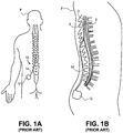
- Figs. 1A-1B illustrate conventional placement of an SCS system 10.
- Conventional SCS systems include an implantable power source or implantable pulse generator (IPG) 12 and an implantable lead 14.
- IPGs 12 are similar in size and weight to cardiac pacemakers and are typically implanted in the buttocks or abdomen of a patient P.
- the lead 14 is implanted into the epidural space E of the spinal column and positioned against the dura layer D of the spinal cord S, as illustrated in Fig. 1B .
- the lead 14 is implanted either through the skin via an epidural needle (for percutaneous leads) or directly and surgically through a mini laminotomy operation (for paddle leads or percutaneous leads).
- a laminotomy is a neurosurgical procedure that removes part of a lamina of the vertebral arch. The laminotomy creates an opening in the bone large enough to pass one or more leads through.
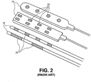
- Fig. 2 illustrates example conventional paddle leads 16 and percutaneous leads 18.
- Paddle leads 16 typically have the form of a slab of silicon rubber having one or more electrodes 20 on its surface.
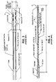
- Example dimensions of a paddle lead 16 are illustrated in Fig. 3 .
- Percutaneous leads 18 typically have the form of a tube or rod having one or more electrodes 20 extending therearound.
- Example dimensions of a percutaneous lead 18 are illustrated in Fig. 4 .
- Implantation of a percutaneous lead 18 typically involves an incision over the low back area (for control of back and leg pain) or over the upper back and neck area (for pain in the arms).
- An epidural needle is placed through the incision into the epidural space and the lead is advanced and steered over the spinal cord until it reaches the area of the spinal cord that, when electrically stimulated, produces a tingling sensation (paresthesia) that covers the patient's painful area.
- the lead is moved and turned on and off while the patient provides feedback about stimulation coverage. Because the patient participates in this operation and directs the operator to the correct area of the spinal cord, the procedure is performed with conscious sedation.
- Implantation of paddle leads 16 typically involves performing a mini laminotomy to implant the lead. An incision is made either slightly below or above the spinal cord segment to be stimulated. The epidural space is entered directly through the opening in the bone and a paddle lead 16 is placed over the region to stimulate the spinal cord. The target region for stimulation usually has been located before this procedure during a spinal cord stimulation trial with percutaneous leads 18.
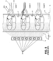
- the lead 14 is positioned upon the spinal cord dura layer D so that the electrodes 20 stimulate a wide portion of the spinal cord and associated spinal nervous tissue (as indicated by perimeter 21).
- the spinal cord is a continuous body and three spinal levels of the spinal cord are illustrated.
- spinal levels are sub-sections of the spinal cord S depicting that portion where the dorsal root DR and ventral root VR join the spinal cord S.
- the spinal nerve N divides into the dorsal root DR and the dorsal root ganglion DRG and the ventral nerve root VR each of which feed into the spinal cord S.
- the dorsal roots DR feed into the posterior side of the spinal cord S and the ventral roots VR feed into the anterior side of the spinal cord S.
- each level shown illustrates the nerves of only one side and a normal anatomical configuration would have similar nerves on the opposite side of the spinal cord.
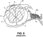
- Fig. 6 illustrates a cross-sectional view of the lead 14 of Fig 5 at a spinal level.
- the lead 14 is positioned against the dura layer D near the midline of the spinal cord S.
- the electrode 20 stimulates a wide portion of the spinal cord.
- the lead 14 is a unidirectional paddle lead so the stimulation energy 15 (indicated by perimeter 21) extends to one side of the lead 14.
- Significant energy 15 is utilized to penetrate the dura layer D and cerebral spinal fluid CSF to activate fibers in the spinal column extending within the posterior side of the spinal cord S, post-synaptically to the dorsal roots.
- omnidirectional leads even more energy may be required due to loss of energy that is directed away from the target.
- a tingling sensation paresthesia
- excessive tingling may be considered undesirable.
- the energy 15 also typically penetrates the anterior side of the spinal cord S, stimulating the ventral horns, and consequently the ventral roots extending within the anterior side of the spinal cord S.
- non-specific stimulation refers to the fact that the stimulation energy is provided to multiple spinal levels including the nerves and the spinal cord generally and indiscriminately. This is the case even with the use of programmable electrode configurations wherein only a subset of the electrodes are used for stimulation. In fact, even if the epidural electrode is reduced in size to simply stimulate only one level, that electrode will apply stimulation energy non-specifically and indiscriminately (i.e. to many or all nerve fibers and other tissues) within the range of the applied energy.
- US-A-2005/0259454 describes a fractional voltage converter.
- US-A-2008/0140152 describes implantable flexible circuit leads and methods of use.
- US-A-2006/0052837 describes methods and systems for modulating neural tissue.
- the present invention provides devices and systems for targeted treatment of a variety of conditions, particularly conditions that are associated with or influenced by the nervous system. Examples of such conditions include pain, itching, Parkinson's Disease, Multiple Sclerosis, demylenating movement disorders, spinal cord injury, asthma, chronic heart failure, obesity and stroke (particularly acute ischemia), to name a few.
- the present invention provides for targeted treatment of such conditions with minimal deleterious side effects, such as undesired motor responses or undesired stimulation of unaffected body regions. This is achieved by directly neuromodulating a target anatomy associated with the condition while minimizing or excluding undesired neuromodulation of other anatomies.
- neuromodulation comprises stimulation, however it may be appreciated that neuromodulation may include a variety of forms of altering or modulating nerve activity by delivering electrical or pharmaceutical agents directly to a target area.
- stimulation and stimulation parameters for illustrative purposes, descriptions herein will be provided in terms of stimulation and stimulation parameters, however, it may be appreciated that such descriptions are not so limited and may include any form of neuromodulation and neuromodulation parameters.
- the systems and devices are used to stimulate portions of neural tissue of the central nervous system, wherein the central nervous system includes the spinal cord and the pairs of nerves along the spinal cord which are known as spinal nerves.
- the spinal nerves include both dorsal and ventral roots which fuse in the intravertebral foramen to create a mixed nerve which is part of the peripheral nervous system.
- At least one dorsal root ganglion (DRG) is disposed along each dorsal root prior to the point of mixing.
- the neural tissue of the central nervous system is considered to include the dorsal root ganglions and exclude the portion of the nervous system beyond the dorsal root ganglions, such as the mixed nerves of the peripheral nervous system.
- the systems and devices of the present invention are used to stimulate one or more dorsal root ganglia, dorsal roots, dorsal root entry zones, or portions thereof, while minimizing or excluding undesired stimulation of other tissues, such as surrounding or nearby tissues, ventral root and portions of the anatomy associated with body regions which are not targeted for treatment.
- other tissues such as surrounding or nearby tissues, ventral root and portions of the anatomy associated with body regions which are not targeted for treatment.
- stimulation of other tissues are contemplated.
- Signal parameters include voltage, current amplitude, pulse width and repetition rate, to name a few.
- the voltage provided is in the range of approximately 0-7 volts.
- the current amplitude provided is less than approximately 4 mA, particularly in the range of approximately 0.5-2mA, more particularly in the range of approximately 0.5-1.0mA, 0.1- 1.0mA, or 0.01-1.0mA.
- the pulse width provided is less than approximately 2000 ⁇ s, particularly less than approximately 100 ⁇ s, more particularly less than approximately 500 ⁇ s, or more particularly 10-120 ⁇ s.
- the repetition rate is in the range of approximately 2-120Hz, up to 200 Hz or up to 1000Hz.
- stimulation parameters are adjusted until satisfactory clinical results are reached.
- the specific combinations or possible combinations that could be used to successfully treat the patient are typically determined perioperatively in vivo and postoperatively ex vivo and depend on a variety of factors.
- One factor is lead placement. The closer the desired electrodes are to the DRG the lower the energy required to stimulate the DRG.
- Other factors include electrode selection, the anatomy of the patient, the pain profiles that are being treated and the psychological perception of pain by the patient, to name a few.
- the parameter values for any given lead to treat the patient may change due to changes in lead placement, changes in impedance or other physical or psychological changes.
- the envelope of parameter values is exceedingly lower than those of conventional stimulation systems which require energy delivery of at least an order of magnitude higher to treat the patient's pain condition.
- the granularity of control is also smaller in comparison to conventional stimulation systems.
- current in a conventional stimulation system is typically adjustable in increments of 0.1 mA.
- this increment is larger than the entire range of current amplitude values that may be used to treat the patient.
- smaller increments are needed to cycle through the signal parameter values to determine the appropriate combination of values to treat the condition.
- the system of the present invention provides control of current amplitude at a resolution of approximately 25 ⁇ A, particularly when using a current amplitude under, for example, 2mA, however it may be appreciated that smaller increments may be used such as approximately 10 ⁇ A, 5 ⁇ A or 1 ⁇ A.
- control of current amplitude is provided at a resolution of approximately 50 ⁇ A, particularly when using a current amplitude of, for example, 2mA or greater. It may be appreciated that such a change in resolution may occur at other levels, such as 1mA.
- voltage in a conventional stimulation system is typically adjustable in increments of 100mV.
- some embodiments of the present invention provide control of voltage at a resolution of 50 mV.
- some embodiments of the present invention provide control of pulse width at a resolution of 10 ⁇ s.
- the present invention provides a high granularity of control of stimulation parameters due to the low ranges of parameter values.
- the average electrode surface area is approximately 1-6mm 2 , particularly approximately 2-4mm 2 , more particularly 3.93mm 2 whereas conventional spinal cord stimulators typically have a much larger average electrode surface area, such as 7.5mm 2 for some leads or 12.7mm 2 for traditional paddle leads.
- an average electrode length is 1.25mm whereas conventional spinal cord stimulators typically have an average electrode length of 3mm.
- Such reduced electrode sizing allows more intimate positioning of the electrodes in the vicinity of the DRG and allows for IPGs having different control and performance parameters for providing direct and selective stimulation of a targeted neural tissue, particularly the DRG.
- the overall dimensions of one or more electrodes and the spacing of the electrodes is selected to match or nearly match the overall dimensions or size of the stimulation target.
- Effective treatment of a condition may be achieved by directly stimulating a target anatomy associated with the condition while minimizing or excluding undesired stimulation of 20 other anatomies.
- a condition is limited to or primarily affects a single dermatome
- the present invention allows for stimulation of a single dermatome or regions within a dermatome (also referred to as subdermatomal stimulation).
- a target DRG is stimulated with a lead having at least one electrode thereon.
- the lead is advanced through the patient anatomy so that the at least one electrode is positioned on, near or about the target DRG.
- the lead is sized and configured so that the electrode(s) are able to minimize or exclude undesired stimulation of other anatomies.
- Such configuration may include a variety of design features, including signal parameters, which will be described herein.
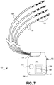
- Fig. 7 illustrates an embodiment of an implantable stimulation system 100 of the present invention.
- the system 100 includes an implantable pulse generator (IPG) 102 and at least one lead 104 connectable thereto.
- IPG implantable pulse generator
- the system 100 includes four leads 104, as shown, however any number of leads 104 may be used including one, two, three, four, five, six, seven, eight, up to 58 or more.
- Each lead 104 includes at least one electrode 106.
- each lead 104 includes four electrodes 106, as shown, however any number of electrodes 106 may be used including one, two, three, four five, six, seven, eight, nine, ten, eleven, twelve, thirteen, fourteen, fifteen, sixteen or more.
- Each electrode can be configured as off, anode or cathode.
- the software ensures only one lead is stimulating at any time. In other embodiments, more than one lead is stimulating at any time, or stimulation by the leads is staggered or overlapping.
- the IPG 102 includes electronic circuitry 107 as well as a power supply 110, e.g., a battery, such as a rechargeable or non-rechargeable battery, so that once programmed and turned on, the IPG 102 can operate independently of external hardware.
- the electronic circuitry 107 includes a processor 109 and programmable stimulation information in memory 108.
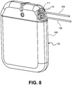
- Fig. 8 provides a perspective view of an embodiment of an IPG 102 of the present invention.
- the electronic circuitry 107 and power supply 110 are enclosed in a housing 105 (also referred to as a "case” or “can”).
- the power supply may be located outside of the housing 105, such as within an external device which supplies power to the IPG 102, such as via inductive coupling, RF or photoactivation.
- the IPG 102 as a volume not exceeding approximately 32cc, , a thickness not exceeding approximately 1.2 cm or a weight not exceeding approximately 30g.
- the IPG 102 has a volume not exceeding approximately, 0.2, 5, 10, 15, 20, 30, 40, 50, 60 or 70 cc.
- the IPG 102 may have a variety of shapes, including an oval, circular, rounded square or rounded rectangular shape.
- the IPG 102 has a height of approximately 61 mm, a width of approximately 48 mm and a thickness of approximately 11mm.
- the housing 105 of the IPG 102 is electrically conductive.
- the housing 105 can act as an electrode, as explained in more detail below.
- the at least one electrode 106 is electrically coupled to the electronic circuitry 107 by coupling the lead 104 to a connector 111 of the IPG 102.
- each lead 104 is insertable into a separate port 115 in the IPG 102 to provide electrical connection to each lead 104.
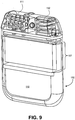
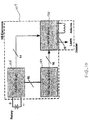
- Fig. 9 illustrates the components within the IPG 102 of Fig. 8 .
- the internal components include a power supply 110, electronic circuitry 107, an antenna 132, and a lead connector 111.
- the electronic circuitry 107 includes three printed circuit boards to allow the circuitry to reside in a small space.
- Fig. 10 provides a schematic block diagram of these boards, which include an RF board 136, an MCU board 138 and an electrode board 140.
- the MCU board includes a microcontroller unit (MCU) which is a small computer on a single integrated circuit comprising a CPU combined with support functions such as a crystal oscillator, timers, serial and analog I/O etc.
- Program memory such as in the form of NOR flash or OTP ROM, may also be included on the chip, as well as RAM. It may be appreciated that the electronic circuitry 107 may include other arrangements and components.
- the IPG 102 is turned on and off and programmed to generate the desired stimulation pulses from at least one external programming device using telemetry, such as transcutaneous electromagnetic or RF links or a transmitting coil.
- telemetry such as transcutaneous electromagnetic or RF links or a transmitting coil.
- an RF link is used which complies with the MICS standard. This standard allocates a 402-405 MHz frequency spectrum intended for implantable medical devices.
- the RF link utilizes a frequency of 400MHz or greater.
- the RF link utilizes a frequency of 2.45GHz.
- telemetry is initiated by a magnet within or associated with the external programmer.
- the magnet actuates a magnetic sensor in the implanted IPG 102 when placed on the skin directly over the implant or within a suitable range of the implant.
- the IPG 102 sniffs on all channels for communication attempts by external programmers. In some embodiments, such sniffing occurs over at predetermined intervals, such as every 10 min, and such intervals can be programmable. This is a backup communication link should the IPG fail to detect the magnet. Should the IPG detect the presence of an external programmer, the IPG typically responds to the programmer within thirty seconds, 15 seconds or less.
- the at least one external programming device comprises a clinical programmer 200 and a patient programmer 300.
- the clinical programmer 200 is used to program the stimulation information of the IPG 102, as determined by the clinician or investigator.
- the stimulation information includes signal parameters such as voltage, current, pulse width, repetition rate, and burst rates.
- Fig. 12 illustrates an example of possible parameters of a stimulation signal which may be varied.
- the amplitude, current, pulse width and repetition rate also referred to as frequency
- a constant current with a variable amplitude may be used, or a constant amplitude with a variable current may be used.
- the patient programmer 300 allows the patient to adjust the stimulation settings of the IPG 102 within limits preset by the clinician.
- the patient programmer 300 also allows the patient to turn stimulation off, if necessary.
- the clinical and patient programmers 200, 300 are portable, hand-held devices that can be plugged into a power outlet or powered by an internal battery. The battery is typically rechargeable using a power supply and a power outlet.
- the programmers 200, 300 contain an internal magnet to initiate communication with the IPG 102.
- the patient programmer 300 is designed to be easy to use and establishes two-way communication with the IPG 102 to control the stimulation. Together the implantable stimulation system 100, clinical programmer 200 and patient programmer 300 form a system 1000 which operates to provide personalized treatment for each patient, as will be described in more detail below.
- Fig. 13 is a simplified block diagram that illustrates possible components of the electronic circuitry of the IPG.
- the electronic circuitry 418 is shown as including a battery 430, pulse generator 432, a controller 434, a switch device 436, telemetry circuitry 438 and memory 439.
- the battery 430 can be used to power the various other components of the electronic circuitry 418. Further, the battery 430 can be used to generate stimulation pulses. As such, the battery can be coupled to the pulse generator 432, the controller 434, the switch device 436, the telemetry circuitry 438 and the memory 439.
- a voltage regulator (not shown) can step up or step down a voltage provided by the battery 430 to produce one or more predetermined voltages useful for powering such components of the electronic circuitry 418.
- Additional electronic circuitry such as capacitors, resistors, transistors, and the like, can be used to generate stimulation pulses, as is well known in the art.
- the pulse generator 432 can be coupled to electrodes 106 of the lead(s) 104 via the switch device 436.
- the pulse generator 432 can be a single- or multi-channel pulse generator, and can be capable of delivering a single stimulation pulse or multiple stimulation pulses at a given time via a single electrode combination or multiple stimulation pulses at a given time via multiple electrode combinations.
- the pulse generator 432 and the switch device 136 are configured to deliver stimulation pulses to multiple channels on a time-interleaved basis, in which case the switch device 436 time division multiplexes the output of pulse generator 432 across different electrode combinations at different times to deliver multiple programs or channels of stimulation energy to the patient.
- the controller 434 can control the pulse generator 432 to generate stimulation pulses, and control the switch device 436 to couple the stimulation energy to selected electrodes. More specifically, the controller 434 can control the pulse generator 432 and the switch device 436 to deliver stimulation energy in accordance with parameters specified by one or more stimulation parameter sets stored within the memory 439. Exemplary programmable parameters that can be specified include the pulse amplitude, pulse width, and pulse rate (also known as repetition rate or frequency) for a stimulation waveform (also known as a stimulation signal). Additionally, the controller 434 can control the switch device 436 to select different electrode configurations for delivery of stimulation energy from the pulse generator 432.
- additional programmable parameters that can be specified include which electrodes 106 of which lead(s) 104 are to be used for delivering stimulation energy and the polarities of the selected electrodes 106.
- Each electrode 106 can be connected as an anode (having a positive polarity), a cathode (having a negative polarity), or a neutral electrode (in which case the electrode is not used for delivering stimulation energy, i.e., is inactive).
- a set of parameters can be referred to as a stimulation parameter set since they define the stimulation therapy to be delivered to a patient.
- One stimulation parameter set may be useful for treating a condition in one location of the body of the patient, while a second stimulation parameter set may be useful for treating a condition in a second location.
- each of the electrodes on an individual lead may provide a signal having the same signal parameters or one or more electrodes on the lead may provide a signal having differing signal parameters.
- an individual electrode may provide a signal having differing signal parameters over time.
- the controller 434 can include a microprocessor, a microcontroller, a digital signal processor (DSP), an application specific integrated circuit (ASIC), a field-programmable gate array (FPGA), a state machine, or similar discrete and/or integrated logic circuitry.
- the switch device 436 can include a switch array, switch matrix, multiplexer, and/or any other type of switching device suitable to selectively couple stimulation energy to selected electrodes.
- the memory 439 can include RAM, ROM, NVRAM, EEPROM or flash memory, but is not limited thereto. Various programs and/or stimulation parameter sets can be stored in the memory 439, examples of which are discussed herein.
- the IPG 102 can be programmed with the optimal parameters of the set.
- the appropriate electrode(s) 106 on the lead 104 then stimulate the nerve tissue with the determined stimulation signal.
- Fig. 14 is a simplified block diagram that illustrates possible components of an external programmer, such as a clinical programmer 200.
- the clinical programmer 200 is shown as including a power supply 440, a user interface 442, a controller 444, input and output (I/O) circuitry 446, telemetry circuitry 448 and memory 449.
- I/O input and output
- the power supply 440 which can include a battery, can be used to power the various other components of the external programmer. As such, the power supply 440 can be coupled to the user interface 442, the controller 444, the input and output (I/O) circuitry 446, the telemetry circuitry 448 and the memory 449.
- a voltage regulator (not shown) can step up or step down a voltage provided by a battery or an external power source to produce one or more predetermined voltages useful for powering such components of the external programmer.
- the clinician or other operator may utilize the clinical programmer 200 to perform a variety of functions.
- the clinical programmer 200 can be used to:
- the clinician may interact with the controller 444 via the user interface 442 in order to test various stimulation parameter sets, input user feedback, select preferred or optimal programs, and the like.
- the user interface 442 can include a display, a keypad, a touch screen, one or more peripheral pointing devices (e.g., a mouse, touchpad, joystick, trackball, etc.), and the like.
- the controller 444 can provide a graphical user interface (GUI) via the user interface 442 to facilitate interaction with the clinician.
- GUI graphical user interface
- the controller 444 can include a microprocessor, a microcontroller, a digital signal processor (DSP), an application specific integrated circuit (ASIC), a field-programmable gate array (FPGA), a state machine, or similar discrete and/or integrated logic circuitry.
- DSP digital signal processor
- ASIC application specific integrated circuit
- FPGA field-programmable gate array
- the I/O circuitry 446 can include transceivers for wireless communication, ports for wired communication and/or communication via removable electrical media, and/or appropriate drives for communication via removable magnetic or optical media.
- the telemetry circuitry 448 can be the telemetry circuitry described above, or separate but similar telemetry circuitry.
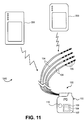
- Fig. 15A provides a perspective expanded view of an embodiment of a clinical programmer 200.
- the clinical programmer 200 comprises a handheld computer 202, such as a personal digital assistant, an antenna 204, a ground plane 206, and a telemetry controller 208 or "Base Station" (micro) plus RF board.
- the handheld computer 202 includes a touch screen user interface 210 and an input and output (I/O) port 212.
- these components are disposed within a housing comprising a cradle 214 and a faceplate 216, as shown.
- the controller 444 can collect information relating to tested electrode parameters (e.g., combinations) and stimulation signal parameters, and store the information in the memory 449 for later retrieval and review by a clinician or by the controller 444 to facilitate identification of one or more preferred stimulation parameter sets.
- the controller 444 can send instructions to the IPG 102 via the telemetry circuit 448 to cause the testing of various stimulation parameter sets. For example, the controller 444 can effectuate the testing of stimulation parameter sets created by the controller 444 or clinician to the IPG 102.
- the memory 449 can include program instructions that, when executed by the controller 444, cause the programmer 422 to perform at least some of the functions described herein.
- the controller 444 can execute program instructions that specify protocols for testing various stimulation parameter sets and selecting one or more preferred stimulation parameter sets.
- the memory 449 can also store one or more stimulation parameter sets determined to treat a particular condition of a patient, along with information about the patient.
- the memory 449 can include any volatile, non-volatile, fixed, removable, magnetic, optical, or electrical media, such as a RAM, ROM, CD-ROM, hard disk, removable magnetic disk, memory cards or sticks, NVRAM, EEPROM, flash memory, and the like.
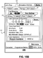
- the clinical programmer 200 includes "workspaces" which are used to view and program the therapy settings and to obtain diagnostic information. A record of the programmed settings and diagnostic information is generated after every session.
- four workspaces are provided: “Patient”, “Leads”, “Therapy” and “Stimulator”.
- Fig. 15B provides an example screenshot 250 of the clinical programmer 200. The four workspaces are shown as workspace tabs 252 near the top of the screenshot 250.
- the Patient Workspace is used to: Enter patient identification information; Enter IPG device information; Enter clinician, clinic name and contact information; and Enter clinician's notes.
- the Patient Workspace is divided into three tabs: "Patient Information", “Clinician", and “Notes".
- Information tab information may be entered such as one or more of the following: Patient Name, Date of birth, Patient Address, Patient ID Number, Stimulator Serial Number, Date of Implant, Lead Serial Numbers.
- the Clinician tab information may be entered such as one or more of the following: Physician Name, Clinic Name, Clinic Address, Clinic Phone Number, Clinic Email Address.
- a text field is provided to enter free text notes. Optionally, any previous information that has been entered in the text field will be erased when the text field is updated.
- the Leads Workspace is used to: Activate (turn on) up to four leads; Adjust electrode configuration; Measure impedance; Set nominal values to begin stimulation; Perform trial mapping; Confirm and assign specific body regions to be stimulated.
- There is one Lead tab for each lead each Lead tab may be labeled with the corresponding body region receiving stimulation.
- Each body region can have stimulation adjusted as described herein.
- Fig. 15B illustrates four body region tabs 254, one each for right foot, left ankle, left foot, and lower back.
- each lead has four electrodes.
- Each of the electrodes can be programmed with a positive or negative pulse, or be programmed as neutral (off).
- the pulse parameters are also programmable.
- the pulse parameters include: Pulse Amplitude ( ⁇ A), Pulse Width ( ⁇ s), Pulse Repetition Rate (Hz), and Allowed Impedance Range ( ⁇ ).
- the Allowed Impedance Range is dependent on voltage and amplitude combinations.
- each pulse parameter is selected from a drop-down table. The parameter choices are specific to a variety of factors, including the anatomical target, and will be described in later sections below.
- each lead has a Maximum Allowable Charge.
- the calculated value of the maximum allowable charge delivered by each lead may be displayed under its associated Lead tab. This value is calculated based on the assigned pulse parameter settings and the lead's electrode configuration. Thus, combinations of amplitude and pulse width selections are typically limited by the maximum allowable charge. Therefore, for certain amplitude settings, only certain pulse width settings may be selectable. Similarly, for certain pulse width settings, only certain amplitude settings may be selectable.
- a Measure Impedance Button is included.
- the Measure Impedance Button is activated to measure the lead's impedance. Once activated, the impedance value may be displayed.
- the clinical programmer 200 is used for Trial Mapping.
- Trial Mapping allows the clinician to test and confirm patient stimulation response for each lead target or body region in real time.
- Trial Mapping starts with the use of signal parameters set to relatively low settings. Parameter settings are increased or decreased by pressing the "Up” or “Down” arrow button respectively.
- Fig. 15C illustrates an embodiment of a screenshot 260 showing a selectable step size buttons 262 when changing parameter settings.
- the granularity of control or step size is also smaller. Thus, smaller increments are needed to cycle through the signal parameter values to determine the appropriate combination of values to treat the condition.
- the clinician may desire a variety of step sizes to narrow the range of parameter values. For example, the clinician may start with a larger step size (>>>) for gross changes in parameters values and then move to a smaller step size (>>) and even smaller step size (>) when approaching the desired parameter value.
- Each enabled lead pulse parameter setting is adjusted until a desired response is achieved.
- the actual step sizes corresponding to the selectable step size buttons 262 are preprogrammed into the programmer 200. It may be appreciated that as the clinician scrolls through different ranges of the parameter values, the step size will automatically change to a granularity appropriate for the range.
- the settings are then saved to memory in preparation for programming of the IPG.
- the Trial Mapping process is then repeated for each activated body region.
- the Therapy workspace is used to: Enable or disable patient controlled therapy for each lead; and Set maximum current amplitude accessible for adjustment by the patient. Selecting "ON” enables Patient Controlled therapy. This allows the patient to adjust therapy settings using their Patient Programmer. Selecting "OFF” disables and blocks patient access to Patient Controlled therapy.
- the clinician When setting Maximum Stimulation Amplitude Settings, the clinician typically enters the maximum stimulation amplitude from a clinically set amplitude, such as up to 4.0 mA, that the patient is allowed to set for each lead.
- the Stimulator Workspace is used to: Acquire identification, diagnostic, and historic information about the IPG; Program the IPG with therapy settings; and Program patient and clinician information.
- the Stimulator Workspace has two tabs, "Information” and "Program". When the "Information" tab is selected, the screen displayed is read only and may display one or more of the following: Neurostimulator Serial Number (displays the serial number for the IPG); NS Firmware Version (displays the Stimulator firmware version); Lead Serial Numbers (Displays each lead's serial number; Neurostimulator Clock Information (displays the time when the IPG was first queried for that specific therapy session); and Implant Battery Information.
- the "Program” tab is used to program the IPG with the configured settings including Leads settings and Patient Controlled therapy settings.
- Patient and Stimulator Identification Information is displayed under the "Program” tab.
- Such information may include Patient Name; Patient Date of birth; Stimulator Serial Number; and Stimulation Therapy Summary Table.
- the Stimulation Therapy Summary Table also referred to as "Stimulator Settings”, displays configured stimulation therapy settings.
- stimulation therapy parameters may be highlighted, such as using red text, to indicate parameters that have been modified since the last stimulation therapy was programmed to the IPG. Data may be presented in this order: Patient, Leads, and Therapy. Use of the vertical scroll bar may be used to display the different parameters.
- a "Program Stimulator” button is provided under the “Program” tab.
- the “Program Stimulator” button is used to transfer the programmed values to the IPG.
- a table below the “Program Stimulator” button displays a summary of the configured stimulation therapy settings.
- a confirmation window may be displayed to confirm whether it is desired to program the IPG. Selecting a "Yes” button programs the settings displayed. Selecting a "No” button cancels programming the IPG.
- the patient programmer 300 that is to be used by the patient is specifically bound to the patient's IPG in order for the patient to be able to minimally adjust the stimulation settings.
- the patient programmer 300 may be bound to multiple IPGs within a patient if the patient has been implanted with more than one IPG.
- Fig. 16 is a simplified block diagram that illustrates possible components of an external programmer, such as a patient programmer 300.
- the patient programmer 300 is shown as including a power supply 450, a user interface 452, a controller 454, input and output (I/O) circuitry 456, telemetry circuitry 458 and memory 459.
- the power supply 450 which can include a battery, can be used to power the various other components of the patient programmer 300.
- the power supply 450 can be coupled to the user interface 452, the controller 454, the input and output (I/O) circuitry 456, the telemetry circuitry 458 and the memory 459.
- a voltage regulator (not shown) can step up or step down a voltage provided by a battery or an external power source to produce one or more predetermined voltages useful for powering such components of the patient programmer 300.
- a patient can interact with the controller 454 via the user interface 452 in order to select, modify or otherwise control delivery of stimulation therapy.
- the patient may be able to select among various stimulation parameter sets that are stored in the memory 459. Additionally, or alternatively, the patient may be able to increase or decrease specific stimulation signal parameters, such as amplitude, to tailor the therapy to the symptoms being experienced at the time.
- the user interface 442 can include a display, a keypad, a touch screen, one or more peripheral pointing devices (e.g., a mouse, touchpad, joystick, trackball, etc.), and the like.
- the controller 454 can provide a graphical user interface (GUI) via the user interface 452 to facilitate interaction with a patient.
- GUI graphical user interface
- the controller 454 can include a microprocessor, a microcontroller, a digital signal processor (DSP), an application specific integrated circuit (ASIC), a field-programmable gate array (FPGA), a state machine, or similar discrete and/or integrated logic circuitry.
- the I/O circuitry 446 can include transceivers for wireless communication, ports for wired communication and/or communication via removable electrical media, and/or appropriate drives for communication via removable magnetic or optical media.
- the memory 459 can store data related to stimulation parameter sets that are available to be selected by the patient for delivery of stimulation therapy to the patient using the IPG 102 implanted within the patient.
- the controller 454 can record usage information and store usage information in the memory 459.
- the memory 459 can include program instructions that, when executed by the controller 454, cause the patient programmer 426 to perform functions ascribed to the patient programmer 300.
- the memory 459 can include any volatile, non-volatile, fixed, removable, magnetic, optical, or electrical media, such as a RAM, ROM, CD-ROM, hard disk, removable magnetic disk, memory cards or sticks, NVRAM, EEPROM, flash memory, and the like.
- Memory in IPG can record impedance data, current, voltage, time of day, time of therapy changes, built in circuit testing, battery data, to name a few.
- the programmer can record the IPG recorded data. This data can then be used to reprogram the IPG.
- the telemetry circuitry 458 allows the controller to communicate with IPG 102, and the input/output circuitry 456 may allow the controller 454 to communicate with the clinician external programmer 200.
- the controller 454 can receive selections of, or adjustments to, stimulation parameter sets made by the patient via the user interface 452, and can transmit the selection or adjustment to the IPG 102 via telemetry circuitry 458.
- the controller 454 can receive such data from the clinician programmer 200 via the input/output circuitry 456 during programming by a clinician or physician. Further, the patient programmer 300 can transmit data relating to stimulation parameter sets to the IPG 102 via the telemetry circuitry 458.
- the patient may utilize the patient programmer 300 to perform a variety of functions.
- the patient programmer 300 can be used to:
- the patient programmer 300 includes a Main Menu which displays two main functions: Adjust Stimulation Settings and Programmer Setup.
- the Adjust Stimulation Settings allows the user to set up communication with the IPG and adjust stimulation settings.
- the Programmer Setup allows the patient to set the Patient Programmer date and time, and to view information about the IPG and Patient Programmer controls.
- the Main Menu has some basic information identifying the device.
- the physician, clinic and the clinic phone number are typically displayed, along with the Programmer Serial Number, Software Version and Base Station Firmware Version.
- the Main Menu may include the IPG connection status, the battery charge level and the time.
- the patient can cause the IPG to check for communication from the patient programmer 300 with the use of a magnet within or associated with the patient programmer 300.
- the patient may place the magnet near the IPG, such as within 6 feet, for a period of time, such as 5 seconds or more.
- the patient can turn stimulation therapy ON or OFF for up to four areas of the body and adjust the amount of stimulation any of those areas are receiving as allowed by the clinical programmer. It may be appreciated that such functionality applies to any number of leads which are implanted and programmed for use.
- the Patient Programmer 300 may display the names of one to four designated body regions that the leads have been placed to stimulate and the patient individually turns stimulation of each region on or off.
- the patient when stimulation is ON, the patient may adjust the amount of stimulation to the body region. For example, once the correct tab has been selected for the specific body region to be adjusted, the patient may press the "Down” button to decrease the stimulation level or press the "Up” button to increase the stimulation level.
- a stimulation level indicator between the "Up” and “Down” buttons moves up or down as the patient changes the stimulation level for the selected body region. Further, the stimulation level indicator may also show the current stimulation level and where it is compared to the maximum set by the clinician. The adjustments may then be saved and the patient can continue to adjust stimulation to other specific body regions.
- the above described implantable stimulation system 100 can be used to stimulate a variety of anatomical locations within a patient's body.
- the system 100 is used to stimulate one or more dorsal roots, particularly one or more dorsal root ganglions.
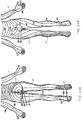
- Fig. 17 illustrates example placement of the leads 104 of the embodiment of Fig. 7 within the patient anatomy.
- each lead 104 is individually advanced within the spinal column S in an antegrade direction.
- Each lead 104 has a distal end which is guidable toward a target DRG and positionable so that its electrodes 106 are in proximity to the target DRG.
- each lead 104 is positionable so that its electrodes 106 are able to selectively stimulate the DRG, either due to position, electrode configuration, electrode shape, electric field shape, stimulation signal parameters or a combination of these as will be discussed in more detail in a later section.
- Fig. 17 illustrates the stimulation of four DRGs, each DRG stimulated by one lead 104. These four DRGs are located on three levels, wherein two DRGs are stimulated on the same level. It may be appreciated that number of DRGs and any combination of DRGs may be stimulated with the stimulation system 100 of the present invention. It may also be appreciated that more than one lead 104 may be positioned so as to stimulate an individual DRG and one lead 104 may be positioned so as to stimulate more than one DRG.
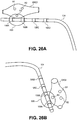
- Fig. 18 illustrates an example cross-sectional view of an individual spinal level showing a lead 104 of the stimulation system 100 positioned on, near or about a target DRG.
- the lead 104 is advanced along the spinal cord S to the appropriate spinal level wherein the lead 104 is advanced laterally toward the target DRG. In some instances, the lead 104 is advanced through or partially through a foramen. At least one, some or all of the electrodes 106 are positioned on, about or in proximity to the DRG. In preferred embodiments, the lead 104 is positioned so that the electrodes 106 are disposed along a surface of the DRG opposite to the ventral root VR, as illustrated in Fig. 18 .
- the surface of the DRG opposite the ventral root VR may be diametrically opposed to portions of the ventral root VR but is not so limited. Such a surface may reside along a variety of areas of the DRG which are separated from the ventral root VR by a distance.
- such electrodes 106 may provide a stimulation region indicated by dashed line 110, wherein the DRG receives stimulation energy within the stimulation region and the ventral root VR does not as it is outside of the stimulation region.
- the electrodes 106 may be positioned in a variety of locations in relation to the DRG and may selectively stimulate the DRG due to factors other than or in addition to distance, such as due to stimulation profile shape and stimulation signal parameters, to name a few.
- the target DRG may be approached by other methods, such as a retrograde epidural approach.
- the DRG may be approached from outside of the spinal column wherein the lead 104 is advanced from a peripheral direction toward the spinal column, optionally passes through or partially through a foramen and is implanted so that at least some of the electrodes 106 are positioned on, about or in proximity to the DRG.
- the lead 104 In order to position the lead 104 in such close proximity to the DRG, the lead 104 is appropriately sized and configured to maneuver through the anatomy. Such maneuvering includes atraumatic epidural advancement along the spinal cord S, through a sharp curve toward a DRG, and optionally through a foramen wherein the distal end of the lead 104 is configured to then reside in close proximity to a small target such as the DRG. Consequently, the lead 104 is significantly smaller and more easily maneuverable than conventional spinal cord stimulator leads.
- the average electrode surface area is approximately 1-6 mm 2 , particularly approximately 2-4 mm 2 , more particularly 3.93 mm 2 whereas conventional spinal cord stimulators typically have a much larger average electrode surface area, such as 7.5 mm 2 for some leads or 12.7mm 2 for traditional paddle leads.
- an average electrode length is 1.25mm whereas conventional spinal cord stimulators typically have an average electrode length of 3mm.
- Such reduced electrode sizing allows more intimate positioning of the electrodes in the vicinity of the DRG and allows for IPGs having different control and performance parameters for providing direct and selective stimulation of a targeted neural tissue, particularly the DRG.
- the overall dimensions of one or more electrodes and the spacing of the electrodes is selected to match or nearly match the overall dimensions or size of the stimulation target.
- the electrode or electrodes arrayed along the lead are sized and spaced so that a majority of the electrodes lie along the overall dimensions of the dorsal root ganglion.
- Fig. 18 illustrates one example where all 4 of the electrodes on the lead are within the lateral dimension of the DRG as shown.
- the size and spacing of the electrodes may align with other DRG dimensions as well.
- the spacing of the electrodes is such that when placed near the targeted dorsal root ganglion two or more electrodes are in position to provide therapeutic energy to the targeted dorsal root ganglion.
- the electrodes 106 are directional so as to provide direct and selective stimulation and further decrease energy required for stimulation.
- the electrodes 106 are spaced 5 mm apart along the distal end of the lead 104. In other embodiments, the electrodes 106 are spaced 0.250 inches apart, from center to center, and 0.200 inches apart, from inside edge to inside edge. In most patients, the DRG has a size of 5-10mm. Therefore, typical spacing would allow two electrodes 106 to be in contact with the target DRG while the remaining two electrodes are in the vicinity of the target DRG. In some instances, the two electrodes 106 in contact with the DRG are used to stimulate the DRG while the remaining two electrodes 106 do not provide stimulation energy.
- all four electrodes 106 provide stimulation energy to the DRG, two electrodes providing energy to the DRG at a distance somewhat closer to the DRG than the other two electrodes. It may be appreciated that any combination of electrodes 106 may provide stimulation energy and each electrode 106 may provide a different level or type of stimulation signal. Consequently, a variety of electric field shapes may be generated, each shape potentially causing a different treatment effect. In many embodiments, the electric field shape will be elliptical. Likewise, the position of the electric field in relation to the anatomy may also be adjusted to potentially cause different treatment effects. Such effects will be described in greater detail below. It may also be appreciated that the electrodes 106 providing stimulation energy may change over time. For example, if a lead 104 has migrated, a different combination of electrodes 106 may be used to stimulate the target DRG in the new lead position.
- the intimate positioning of the leads 104 of the present invention allows the stimulation system 100 to have a variety of additional beneficial features. For example, positioning the leads 104 in such close proximity to the target tissue allows for smaller stimulation regions. This in turn allows for smaller electrode surface areas and reduced energy requirements. A reduction in energy requirements allows for smaller battery size, increased battery longevity and the possibility of the elimination of battery replacement or recharging altogether.
- patients with conventional systems either have an IPG with a standard battery wherein the IPG is surgically replaced when the battery wears out or they have an IPG with a rechargeable battery wherein the battery is recharged by an external device worn for a few hours every two or three weeks.
- the system 100 of the present invention draws such low energy that the battery longevity is sufficient for the life of the device.
- the patient will not need to undergo additional surgeries to replace the battery, therefore reducing any risks of surgical complications.
- the patient will also not need to recharge the battery which increases quality of life and provides for more continuous therapy. In both cases, less clinical follow-up may be necessary which reduces costs and increases patient satisfaction.
- rechargeable batteries may be used.
- the energy requirement for the stimulation system 100 of the present invention is exceptionally low, particularly in comparison to conventional spinal cord stimulation systems.
- the unit of power is the watt. One watt equals 1 joule/second.
- energy is the work done in moving an electric charge (q) between two points with a potential difference between them. Since power equals the derivative of energy, energy equals the integral of power.
- the unit of energy is joules. The movement of electric charge (q) between these two points depends on the resistance R.
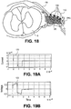
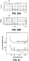
- the stimulation signal of the present invention has a rectangular waveform, such as illustrated by a trace 120 shown in Fig. 19A , wherein the pulse width is approximately 80 ⁇ s and the current amplitude is approximately 200 ⁇ A.
- the integral of this curve i.e. the area under this curve
- the total charge is the total charge, corresponding to the energy and related to tissue impedance.
- Fig. 19B illustrates an embodiment of a trace 122 showing the voltage response to a complex impedance stimulating biological tissue.
- the total energy used is 7nJ, wherein the Warburg resistance is 650 ⁇ , the Warburg capacitance is 0.2 ⁇ F and the tissue resistance is 1000 ⁇ .
- Fig. 20A illustrates a trace 124 representing an example stimulation signal of a conventional spinal cord stimulator.
- the pulse width is approximately 200 ⁇ s and the current amplitude is approximately 1.7mA (or 1700 ⁇ A) which is around an order of magnitude greater than the current amplitude of the stimulation system 100 of the present invention.
- Fig. 20B illustrates an embodiment of a trace 126 representing the voltage response to a complex impedance stimulating biological tissue.
- the total energy used is 1294nJ, wherein the Warburg resistance is 200 ⁇ , the Warburg capacitance is 0.5 ⁇ F and the tissue resistance is 1000 ⁇ .
- the energy supplied by the stimulation system 100 of the present invention is 0.54% (7nJ/1294nJ) of the energy supplied by conventional stimulation systems. This significant reduction in energy is due to the lower energy requirements of selectively stimulating the target anatomy, particularly the DRG.
- the energy supplied by the stimulation system 100 of the present invention is less than 10% of conventional systems, particularly less than 5%, more particularly less than 1%.
- Fig. 21 illustrates additional data indicating the stimulation signal parameters which selectively targeted the DRG. As shown, there is an energy threshold in which the DRG is stimulated which is below the energy threshold in which the ventral root is stimulated. By providing stimulation signals below the ventral root threshold, the patient's pain sensations may be blocked without the negative side effects of ventral root stimulation.
- Signal parameters include voltage, current amplitude, pulse width and repetition rate, to name a few.
- the voltage provided is in the range of approximately 0-7 volts.
- the current amplitude provided is less than approximately 4 mA, particularly in the range of approximately 0.5-2mA, more particularly in the range of approximately 0.5-1.0mA, 0.1- 1.0mA, or 0.01-1.0mA.
- the pulse width provided is less than approximately 2000 ⁇ s, particularly less than approximately 1000 ⁇ s, more particularly less than approximately 500 ⁇ s, or more particularly 10-120 ⁇ s.
- the repetition rate is in the range of approximately 2-120Hz, up to 200 Hz or up to 1000Hz.
- stimulation parameters are adjusted until satisfactory clinical results are reached.
- the specific combinations or possible combinations that could be used to successfully treat the patient are typically determined perioperatively in vivo and postoperatively ex vivo and depend on a variety of factors.
- One factor is lead placement. The closer the desired electrodes are to the DRG the lower the energy required to stimulate the DRG.
- Other factors include electrode selection, the anatomy of the patient, the pain profiles that are being treated and the psychological perception of pain by the patient, to name a few.
- the parameter values for any given lead to treat the patient may change due to changes in lead placement, changes in impedance or other physical or psychological changes.
- the envelope of parameter values is exceedingly lower than those of conventional stimulation systems which require energy delivery of at least an order of magnitude higher to treat the patient's pain condition.
- the granularity of control is also smaller in comparison to conventional stimulation systems.
- current in a conventional stimulation system is typically adjustable in increments of 0.1 mA. In some embodiments of the present invention, this increment is larger than the entire range of current amplitude values that may be used to treat the patient. Thus, smaller increments are needed to cycle through the signal parameter values to determine the appropriate combination of values to treat the condition.
- the system 100 of the present invention provides control of current amplitude at a resolution of approximately 25 ⁇ A, particularly when using a current amplitude under, for example, 2mA, however it may be appreciated that smaller increments may be used such as approximately 10 ⁇ A, 5 ⁇ A or 1 ⁇ A.
- control of current amplitude is provided at a resolution of approximately 50 ⁇ A, particularly when using a current amplitude of, for example, 2mA or greater. It may be appreciated that such a change in resolution may occur at other levels, such as 1mA.
- voltage in a conventional stimulation system is typically adjustable in increments of 100mV.
- some embodiments of the present invention provide control of voltage at a resolution of 50 mV.
- some embodiments of the present invention provide control of pulse width at a resolution of 10 ⁇ s.
- the present invention provides a high granularity of control of stimulation parameters due to the low ranges of parameter values.
- the stimulation profile is customized for the patient and programmed into the memory 108 of the IPG 102.
- the IPG 102 is typically programmed through a computerized programming station or programming system.
- This programming system is typically a self-contained hardware/software system, or can be defined predominately by software running on a standard personal computer (PC).
- the PC or custom hardware can have a transmitting coil attachment or antenna to allow for the programming of implants, or other attachments to program external units.
- Patients are generally provided hand-held programmers (patient programmer 300) that are more limited in scope than are the physician-programming systems (clinical programmer 200), with such hand-held programmers still providing the patient with some control over selected parameters. Thus, this allows for easy changes to the stimulation profile over time, as needed.
- a condition may be achieved by directly stimulating a target anatomy associated with the condition while minimizing or excluding undesired stimulation of other anatomies.
- the present invention allows for stimulation of a single dermatome or regions within a dermatome (also referred to as subdermatomal stimulation).
- a dermatome is considered the body region that is innervated by a single spinal level.
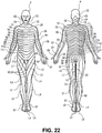
- Fig. 22 illustrates the dermatomal arrangement or "map" of dermatomes along a patient P.
- the dermatomes form into bands around the trunk but in the limbs their organization is more complex as a result of the dermatomes being "pulled out” as the limb buds form and develop into the limbs during embryological development.
- Each dermatome is labeled according to its associated spinal level.
- Upper bodily regions are innervated by nerves traveling in the cervical spinal segments and as the innervation pattern progresses caudally so do the spinal segments innervating the dermatome.
- regions in the middle of the body thorax, etc
- lower bodily regions are innervated by lumbar and sacral spinal segments.
- the nerves innervating a dermatome originate from DRGs on the associated spinal level Since each dermatome is supplied by a single pair of DRGs, stimulation of one or both of these DRGs will substantially effect a single dermatome.
- the present invention provides for stimulation of a single DRG or a pair of DRGs on a single spinal level independently of other DRGs or nerve tissues in the surrounding area. This allows for a single dermatome to be stimulated. It may be appreciated that there is overlap of innervation between adjacent dermatomes. However, stimulation of one or more DRGs on a spinal level will largely affect the directly associated dermatome with significantly lesser affects in adjacent dermatomes.
- stimulation of a single DRG on, for example, the right side of the spinal column will largely affect the right side of the body within the directly associated dermatome.
- stimulation of a single DRG may stimulate a portion of a single dermatome. This is not the case with conventional spinal stimulation systems which simultaneously stimulate multiple dermatomes. By design, such conventional systems cannot isolate a single dermatome or a portion of a dermatome for treatment and such stimulation will substantially affect more than one dermatome.
- Fig. 23 schematically illustrates DRGs on various spinal levels with associated body regions that may be affected by selective stimulation of the individual DRGs.
- stimulation of DRG1 on the right side of L5 may affect the foot, lower leg and/or low back on the right side of the patient.
- stimulation of DRG2 on the right side of L4 may affect the leg and/or low back on the right side of the patient.
- Figs. 24A-25B illustrate these body regions along the dermatomes of the patient P.
- Fig. 24A illustrates the patient P from the back, including the dermatomes of the lower body and a schematic representation of the general area of the DRGs.
- the region of the L5 dermatome that is likely affected by stimulation of DRG1 is indicated by double-hatched lines.
- Fig. 24B illustrates the patient P from the front, including the dermatomes of the lower body.
- the region of the L5 dermatome that is likely affected by stimulation of DRG1 is indicated by double-hatched lines. This portion of the dermatome extends along the bottom of the right foot, the top of the right foot, along the lower leg and up to the low back.
- the region of the L4 dermatome that is likely affected by stimulation of DRG2 is indicated by hatched lines in both Fig. 24A and Fig. 24B .
- This portion of the dermatome mainly extends along the front of the lower leg and up to the low back.
- DRG1 and DRG2 may be stimulated so as to treat such conditions while minimally or not affecting other body regions.
- a conventional spinal stimulation system such as illustrated in Fig. 5
- the lead 14 is positioned along the midline of the spinal column S so that the electrodes 20 are aligned with the saggittal and parasaggittal midline.
- Such placement causes the electrodes 20 to stimulate many neural fibers innervating body regions unassociated and unaffected by the condition for which treatment is desired.
- stimulation by the electrodes 20 would affect the T12, L1, L2, L3, L4, L5 dermatomes on both sides of the patient's body.
- Fig. 25 schematically illustrates selective stimulation of DRG1 according to aspects of the present invention.
- a lead 104 is positioned so that at least one of the at least one electrode 106 is positioned on, near or about the target DRG (DRG1).
- DRG1 target DRG
- Different body regions associated with DRG1 foot, lower leg, low back
- each sensory neuron includes a cell body or soma which may be targeted to stimulate the sensory neuron independently of other surrounding neurons.
- the lower leg is associated with soma N1
- the low back is associated with soma N2
- the foot is associated with soma N3. It has been suggested by a variety of scientific studies that there is a specific somatotopic orientation of neurons (and associated somas) within the DRG subserving sensory function to distinct anatomy.
- a somatotopic map is an anatomically specific orientation of sensory integration. It is well-known that once sensory information has traveled into the central nervous system, a "somatotopic" map is organized in the cortex of the brain. Thus, specific regions of the somatosensory cortex are involved in sensory processing from specific anatomical regions. Thus, stimulation of various regions of specific sub-regions of the somatosensory cortex will result in the perception of sensory input from specific anatomical regions. In addition, research has suggested that not only are there somatotopic maps within the central nervous system, but also in spinal neural structures such as the dorsal root ganglion.
- the dorsal root ganglion is a special neural structure that contains the cell bodies (soma) of the neurons that are innervating specific dermatomes.
- the understanding of a somatotopic map for the dorsal root ganglion may allow for the targeting of portions of the DRG to provide therapy to one or more specific regions within the dermatome associated with that DRG.
- subdermatomal targeting may allow very specific therapeutic application in the treatment of pain and other conditions.
- portions of the DRG may be selectively stimulated to affect specific regions within a dermatome.
- soma N1, soma N2, or soma N3 may be stimulated to cause different treatment effects.
- two or more of the somas N1, N2, N3 may be stimulated in combination to cause further treatment effects.
- Each soma may be selectively stimulated by manipulation of one or more of the following features: position of the electrode(s) 106 in relation to the DRG, selection of the electrode combinations for stimulation, and programming of the stimulation signal parameters, such as pulse width, amplitude, and frequency.
- a desired electrical field is generated and positioned relative to the DRG to stimulate a particular portion of the DRG in three-dimensional space. This particular portion typically includes the one or more somas which are targeted to influence the desired treatment effect.
- Figs. 26A-26D illustrate perspective views of a lead 104 stimulating a portion of DRG1 to affect a specific region within a dermatome.
- DRG1 is shown to include soma N1, soma N2, and soma N3.
- the lead 104 is positioned on, near or about the DRG1 according to the methods of the present invention.
- two electrodes 106a, 106b are selected for stimulation while the remaining two electrodes 106c, 106d are neutral.
- An electric field 500 is generated by the two electrodes 106a, 106b according to chosen stimulation signal parameters so as to stimulate soma N3 while providing minimal or no stimulation to soma N1 and soma N2.
- soma N3 is associated with the body region of the foot whereas soma N1 is associated with the low back and soma N2 is associated with the lower leg.
- Fig. 26B rotates the view of Fig. 26A to illustrate the three-dimensional electric field 500 and its inclusion of soma N3 along with exclusion of soma N1 and soma N2.
- Fig. 26C rotates the view of Fig. 26A to provide a perspective end view, wherein again the three-dimensional electric field 500 is shown to include soma N3 while excluding soma N1 and soma N2.
- Fig. 25D rotates the view of Fig. 25A to provide a perspective bottom view of the lead 104 in proximity to the DRG1 so that the electric field 500 stimulates soma N3 while excluding soma N1 and soma N2.
- Different somas may be selectively stimulated by physically moving the lead 104 in relation to the DRG1.
- the electric field 500 can be moved to select different somas, such as soma N1 while excluding somas N2, N3.
- the lead 104 can remain stationary in relation to the DRG1, and different electrodes 106 may be utilized for stimulation to move the electric field 500.
- the shape of the electric field 500 can be changed by changing the electrode combination and/or changing the stimulation signal parameters.
- the electric field 500 may be increased in size by changing stimulation signal parameters, such as increasing the amplitude.
- the size of the electric field 500 may be increased by changing the electrode combination, such as by utilizing an additional electrode for stimulation.
- the size of the electric field 500 may be increased to include both soma N3 and soma N1, while substantially excluding soma N2. This would cause the patient to have a targeted treatment effect in the foot and low back without a treatment effect in the lower leg within the same dermatome.
- the size of the electric field 500 may be increased to include somas N1, N2, N3. This would cause the patient to have a targeted treatment effect in the foot, low back and lower leg within the same dermatome.
- Figs. 27-28 provide clinical data which illustrate the correlation between changes in electrode combination and/or signal parameters and the resultant changes in affected body region.
- the clinical data was gathered during a clinical trial in which the patient subjects were implanted with one or more leads 104 in accordance with the present invention.
- Each lead 104 was positioned so that at least one of its one or more electrodes 106 was on, near or about a DRG, such as illustrated in Figs. 17-18 .
- the parameter settings were not necessarily within the desired ranges for treatment.
- the bottom of the patient's foot was affected by the stimulation.
- the amplitude was raised to 1.8mA while all other variables remained the same. Consequently, both the patient's foot and calf were affected by the stimulation.
- the electric field provided by Contact 3 and Contact 4 was enlarged causing additional sensory neurons to be stimulated.
- Row 3 of the table shows that when the amplitude was raised to 2.25mA, the affected body region was expanded to include the back of the knee.
- Row 4 of the table shows that when the amplitude was raised to 2.75mA, the affected body region was expanded to include the hip and Row 5 of the table shows that when the amplitude was raised to 3.0mA, the affected body region was expanded to include the buttock.
- additional sensory neurons were stimulated causing additional body regions of the dermatome to be affected. This illustrates that subdermatomal stimulation may be achieved by manipulating the electric field and signal parameters.
- the parameter settings were not necessarily within the desired ranges for treatment.
- the patient's calf was affected by the stimulation.
- the amplitude was raised to 350 ⁇ A while all other variables remained the same. Consequently, both the patient's calf and knee were affected by the stimulation.
- the electric field provided by Contact 3 and Contact 4 was enlarged causing additional sensory neurons to be stimulated.
- Row 3 of the table shows that when the amplitude was raised to 425 ⁇ A, the affected body region was expanded to include the hip.
- additional sensory neurons were stimulated causing additional body regions of the dermatome to be affected.
- Row 4 of the table of Fig 28 shows a change in the electrode configuration.
- Contact 1 remained Off or Neutral (N) while Contact 2 was configured as a cathode (-), Contact 3 was configured as an anode (+) and Contact 4 was configured as a cathode (-).
- Row 5 and Row 6 illustrate the effect of changing electrode configuration while other variables remain the same.
- Contact 1 was Off or Neutral (N) while Contact 2 was configured as a cathode (-)
- Contact 3 was configured as an anode (+)
- Contact 4 was configured as a cathode (-).
- subdermatomal stimulation is achieved by factors other than or in addition to somatotopic mapping of the DRG.
- body regions that are considered as focal areas of the condition for which the patient is being treated were preferentially affected by the stimulation.
- body regions that the patient considered to be painful are preferentially affected by the stimulation.
- DRG stimulation therapy preferentially neuromodulates neural elements that are involved in the pain condition specific to the area of pain. This corroborates with basic neurophysiologic data that suggest both small diameter soma and large diameter neurons residing in the DRG involved in the neural transduction of pain and other somatosensory signals undergo physiologic changes that affect the biophysics of the cell membrane.
- a variety of pain-related conditions are treatable with the systems, methods and devices of the present invention.
- the following conditions may be treated:
- the described systems and devices may alternatively or additionally be used to stimulate ganglia or nerve tissue.
- the condition to be treated is associated with the ganglia or nerve tissue so that such stimulation provides effective therapy.
- the following is a list of conditions or indications with its associated ganglia or nerve tissue:
- the described systems and devices o may also be used to stimulate various other nerve tissue including nerve tissue of the peripheral nervous system, somatic nervous system, autonomic nervous system, sympathetic nervous system, and parasympathetic nervous system, to name a few.
- nerve tissue of the peripheral nervous system somatic nervous system, autonomic nervous system, sympathetic nervous system, and parasympathetic nervous system
- Various features of the systems and devices may be particularly suited for stimulation of portions of these nervous systems.
- the systems and devices of the present invention may be used to stimulate other tissues, such as organs, skin, muscle, etc.
- the lead is described herein as positionable so that the at least one electrode is on, near or about a target anatomy, at least one of the at least one electrode may optionally be positioned in the target anatomy.
Landscapes
- Health & Medical Sciences (AREA)
- Engineering & Computer Science (AREA)
- General Health & Medical Sciences (AREA)
- Life Sciences & Earth Sciences (AREA)
- Veterinary Medicine (AREA)
- Public Health (AREA)
- Animal Behavior & Ethology (AREA)
- Biomedical Technology (AREA)
- Nuclear Medicine, Radiotherapy & Molecular Imaging (AREA)
- Radiology & Medical Imaging (AREA)
- Neurosurgery (AREA)
- Neurology (AREA)
- Orthopedic Medicine & Surgery (AREA)
- Heart & Thoracic Surgery (AREA)
- Cardiology (AREA)
- Pain & Pain Management (AREA)
- Human Computer Interaction (AREA)
- Electrotherapy Devices (AREA)
Claims (14)
- System (100) zur Stimulierung eines Ziel-Rückenwurzelganglions des Zentralnervensystems das Folgendes umfasst:eine Leitung (104) mit mindestens einer Elektrode (106), wobei die Leitung dafür konfiguriert ist, so positioniert zu werden, dass die mindestens eine Elektrode das Ziel-Rückenwurzelganglion stimulieren kann, einen implantierbaren Impulsgenerator (102), der mit der Leitung verbunden werden kann, wobei der Generator dafür konfiguriert ist, ein Stimulationssignal mit einer Stromamplitude bereitzustellen, die in Inkrementen von 50 µA oder weniger einstellbar ist; undeinen externen Programmierer (200, 300), der drahtlos mit dem implantierbaren Impulsgenerator (102) kommuniziert, um Parameter des Stimulationssignals einzustellen; wobei der externe Programmierer dafür konfiguriert ist, einen oder mehrere Benutzeroberflächenbildschirme zum Abbilden der Patientenstimulationsantwort bereitzustellen, um einen oder mehrere bevorzugte Stimulationsparametersätze zu identifizieren;wobei der externe Programmierer dafür konfiguriert ist, eine Parametereinstellung unter Verwendung der ersten Inkremente einer ersten aktuellen Schrittgröße und der zweiten Inkremente einer zweiten aktuellen Schrittgröße zu ermöglichen, und wobei die zweite aktuelle Schrittgröße kleiner als die erste aktuelle Schrittgröße ist, um die Identifizierung der verschiedenen Subdermatomregionen zu ermöglichen.
- System (100) nach Anspruch 1, wobei die Stromamplitude in Inkrementen von 25 µA oder weniger einstellbar ist.
- System (100) nach Anspruch 1 oder Anspruch 2, wobei das System dafür konfiguriert ist, dass, wenn eine Stromamplitude des Stimulationssignals über einem vorbestimmten Niveau liegt, die Stromamplitude in den ersten Inkrementen von ca. 50µA einstellbar ist, und wenn eine Stromamplitude des Stimulationssignals unter dem vorgegebenen Wert liegt, die Stromamplitude in den zweiten Inkrementen von ungefähr 25 µA oder weniger einstellbar ist.
- System (100) nach Anspruch 3, wobei die zweiten Inkremente ungefähr 25 µA betragen.
- System (100) nach einem der Ansprüche 3 oder 4, wobei das vorbestimmte Niveau ungefähr 2 mA beträgt.
- System (100) nach einem der Ansprüche 3 oder 4, wobei das vorbestimmte Niveau ungefähr 1 mA beträgt.
- System (100) nach einem der vorhergehenden Ansprüche, wobei der externe Programmierer dafür konfiguriert ist, die Schrittgröße basierend auf einem Parameterbereich automatisch zu ändern.
- System (100) nach einem der vorhergehenden Ansprüche, wobei die mindestens eine Elektrode (106) eine durchschnittliche Elektrodenoberfläche von weniger als oder gleich ungefähr 6 mm2 aufweist.
- System (100) nach einem der Ansprüche 1 bis 7, wobei die mindestens eine Elektrode (106) eine durchschnittliche Elektrodenoberfläche von weniger als oder gleich ungefähr 4 mm2 aufweist.
- System (100) nach einem der vorhergehenden Ansprüche, wobei der implantierbare Impulsgenerator (102) dafür konfiguriert ist, ein Stimulationssignal bereitzustellen, das eine Energie von weniger als ungefähr 100 nJ pro Impuls aufweist.
- System (100) nach einem der vorhergehenden Ansprüche, wobei das System ferner eine zweite Leitung mit mindestens einer Elektrode umfasst, wobei der implantierbare Impulsgenerator (102) mit der zweiten Leitung verbunden werden kann, um ein Stimulationssignal an die zweite Leitung zu liefern, wobei die zweite Leitung dafür konfiguriert ist, so positioniert zu werden, dass mindestens eine der mindestens einen Elektrode der zweiten Leitung einen Abschnitt eines zweiten Ziel-Nervengewebes stimulieren kann.
- System (100) nach Anspruch 11, wobei das zweite Ziel-Nervengewebe ein zweites Ziel-Rückenwurzelganglion ist.
- System (100) nach Anspruch 11 oder 12, wobei sich das Ziel-Nervengewebe und das zweite Ziel-Nervengewebe auf verschiedenen Wirbelsäulenebenen befinden.
- System (100) nach einem der Ansprüche 11 bis 13, wobei der implantierbare Impulsgenerator (102) dafür konfiguriert ist, unterschiedliche Stimulationssignale an die Leitung (104) und die zweite Leitung zu liefern.
Applications Claiming Priority (3)
| Application Number | Priority Date | Filing Date | Title |
|---|---|---|---|
| US10883608P | 2008-10-27 | 2008-10-27 | |
| PCT/US2009/062259 WO2010062622A2 (en) | 2008-10-27 | 2009-10-27 | Selective stimulation systems and signal parameters for medical conditions |
| EP09744875.7A EP2373378B1 (de) | 2008-10-27 | 2009-10-27 | Selektive stimulationssysteme und signalparameter für medizinische erkrankungen |
Related Parent Applications (2)
| Application Number | Title | Priority Date | Filing Date |
|---|---|---|---|
| EP09744875.7A Division EP2373378B1 (de) | 2008-10-27 | 2009-10-27 | Selektive stimulationssysteme und signalparameter für medizinische erkrankungen |
| EP09744875.7A Division-Into EP2373378B1 (de) | 2008-10-27 | 2009-10-27 | Selektive stimulationssysteme und signalparameter für medizinische erkrankungen |
Publications (2)
| Publication Number | Publication Date |
|---|---|
| EP3202457A1 EP3202457A1 (de) | 2017-08-09 |
| EP3202457B1 true EP3202457B1 (de) | 2020-05-27 |
Family
ID=41480096
Family Applications (2)
| Application Number | Title | Priority Date | Filing Date |
|---|---|---|---|
| EP17159449.2A Active EP3202457B1 (de) | 2008-10-27 | 2009-10-27 | Selektive stimulationssysteme und signalparameter für medizinische zustände |
| EP09744875.7A Active EP2373378B1 (de) | 2008-10-27 | 2009-10-27 | Selektive stimulationssysteme und signalparameter für medizinische erkrankungen |
Family Applications After (1)
| Application Number | Title | Priority Date | Filing Date |
|---|---|---|---|
| EP09744875.7A Active EP2373378B1 (de) | 2008-10-27 | 2009-10-27 | Selektive stimulationssysteme und signalparameter für medizinische erkrankungen |
Country Status (7)
| Country | Link |
|---|---|
| US (7) | US9056197B2 (de) |
| EP (2) | EP3202457B1 (de) |
| JP (1) | JP5643764B2 (de) |
| CN (1) | CN102202729B (de) |
| AU (1) | AU2009320106B2 (de) |
| CA (1) | CA2740791C (de) |
| WO (1) | WO2010062622A2 (de) |
Families Citing this family (138)
| Publication number | Priority date | Publication date | Assignee | Title |
|---|---|---|---|---|
| US20120277839A1 (en) | 2004-09-08 | 2012-11-01 | Kramer Jeffery M | Selective stimulation to modulate the sympathetic nervous system |
| US7337005B2 (en) | 2004-09-08 | 2008-02-26 | Spinal Modulations, Inc. | Methods for stimulating a nerve root ganglion |
| US9205261B2 (en) | 2004-09-08 | 2015-12-08 | The Board Of Trustees Of The Leland Stanford Junior University | Neurostimulation methods and systems |
| US20070073354A1 (en) | 2005-09-26 | 2007-03-29 | Knudson Mark B | Neural blocking therapy |
| CN101573079A (zh) | 2006-12-06 | 2009-11-04 | 脊髓调制公司 | 硬组织锚固件和输送装置 |
| US8983624B2 (en) | 2006-12-06 | 2015-03-17 | Spinal Modulation, Inc. | Delivery devices, systems and methods for stimulating nerve tissue on multiple spinal levels |
| US11679261B2 (en) | 2007-03-09 | 2023-06-20 | Mainstay Medical Limited | Systems and methods for enhancing function of spine stabilization muscles associated with a spine surgery intervention |
| WO2008112178A1 (en) | 2007-03-09 | 2008-09-18 | Dan Sachs | Muscle stimulator |
| US11679262B2 (en) | 2007-03-09 | 2023-06-20 | Mainstay Medical Limited | Systems and methods for restoring muscle function to the lumbar spine |
| US10925637B2 (en) | 2010-03-11 | 2021-02-23 | Mainstay Medical Limited | Methods of implanting electrode leads for use with implantable neuromuscular electrical stimulator |
| US11331488B2 (en) | 2007-03-09 | 2022-05-17 | Mainstay Medical Limited | Systems and methods for enhancing function of spine stabilization muscles associated with a spine surgery intervention |
| US9072897B2 (en) | 2007-03-09 | 2015-07-07 | Mainstay Medical Limited | Systems and methods for restoring muscle function to the lumbar spine |
| US20090204173A1 (en) | 2007-11-05 | 2009-08-13 | Zi-Ping Fang | Multi-Frequency Neural Treatments and Associated Systems and Methods |
| US7890182B2 (en) | 2008-05-15 | 2011-02-15 | Boston Scientific Neuromodulation Corporation | Current steering for an implantable stimulator device involving fractionalized stimulation pulses |
| CA2740791C (en) | 2008-10-27 | 2017-08-01 | Spinal Modulation, Inc. | Selective stimulation systems and signal parameters for medical conditions |
| US8255057B2 (en) | 2009-01-29 | 2012-08-28 | Nevro Corporation | Systems and methods for producing asynchronous neural responses to treat pain and/or other patient conditions |
| US20130110195A1 (en) | 2009-01-15 | 2013-05-02 | Autonomic Technologies, Inc. | Neurostimulator system, apparatus, and method |
| AU2010229985B2 (en) | 2009-03-24 | 2015-09-17 | Spinal Modulation, Inc. | Pain management with stimulation subthreshold to paresthesia |
| AU2010238752B2 (en) | 2009-04-22 | 2014-05-29 | Nevro Corporation | Spinal cord modulation for inducing paresthetic and anesthetic effects, and associated systems and methods |
| EP2243510B1 (de) | 2009-04-22 | 2014-04-09 | Nevro Corporation | Systeme zur selektiven Hochfrequenzrückenmarksmodulation zur Vermeidung von Schmerzen mit weniger Nebenwirkungen |
| US8498710B2 (en) | 2009-07-28 | 2013-07-30 | Nevro Corporation | Linked area parameter adjustment for spinal cord stimulation and associated systems and methods |
| WO2011112773A2 (en) | 2010-03-11 | 2011-09-15 | Mainstay Medical, Inc. | Modular stimulator for treatment of back pain, implantable rf ablation system and methods of use |
| US11684774B2 (en) | 2010-03-11 | 2023-06-27 | Mainstay Medical Limited | Electrical stimulator for treatment of back pain and methods of use |
| US9339645B2 (en) | 2010-05-02 | 2016-05-17 | Nervive, Inc. | Modulating function of the facial nerve system or related neural structures via the ear |
| US9272157B2 (en) | 2010-05-02 | 2016-03-01 | Nervive, Inc. | Modulating function of neural structures near the ear |
| CN103079489B (zh) | 2010-05-10 | 2016-11-16 | 脊髓调制公司 | 用于减少迁移的方法、系统和装置 |
| WO2012075198A2 (en) | 2010-11-30 | 2012-06-07 | Nevro Corporation | Extended pain relief via high frequency spinal cord modulation, and associated systems and methods |
| CA2819635A1 (en) | 2010-12-01 | 2012-06-07 | Spinal Modulation, Inc. | Directed delivery of agents to neural anatomy |
| EP2661307A4 (de) | 2011-01-03 | 2014-08-06 | Univ California | Hochdichte epidurale stimulation zur erleichterung von fortbewegungen, haltungen, willkürlichen bewegungen und zur rückgewinnung autonomer, sexueller, vasomotorischer und kognitiver funktionen nach neurologischen verletzungen |
| JP2014508581A (ja) | 2011-01-21 | 2014-04-10 | カリフォルニア インスティテュート オブ テクノロジー | 脊髄刺激のためのパリレンベースのマイクロ電極アレイインプラント |
| CA2831062A1 (en) * | 2011-01-28 | 2012-08-02 | Stimwave Technologies Incorporated | Neural stimulator system |
| WO2012106548A2 (en) * | 2011-02-02 | 2012-08-09 | Spinal Modulation, Inc. | Devices, systems and methods for the targeted treatment of movement disorders |
| CN107361741B (zh) | 2011-03-24 | 2021-03-09 | 加利福尼亚理工学院 | 神经刺激器装置 |
| BR112013025521B1 (pt) | 2011-04-04 | 2021-04-13 | Micron Devices Llc | Condutor estimulador neural implantável sem fio |
| US9220897B2 (en) | 2011-04-04 | 2015-12-29 | Micron Devices Llc | Implantable lead |
| US8843206B2 (en) | 2011-04-13 | 2014-09-23 | Spinal Modulation, Inc. | Telemetry antennas for medical devices and medical devices including telemetry antennas |
| US11413458B2 (en) | 2011-05-19 | 2022-08-16 | Neuros Medical, Inc. | Nerve cuff electrode for neuromodulation in large human nerve trunks |
| EP3747507B1 (de) | 2011-07-29 | 2023-11-01 | Curonix LLC | Fernsteuerung der leistungs- oder polaritätsauswahl für einen nervenstimulator |
| EP3912675A1 (de) | 2011-08-12 | 2021-11-24 | Stimwave Technologies Incorporated | Mikrowellenfeldstimulator |
| WO2013036880A1 (en) | 2011-09-08 | 2013-03-14 | Thacker James R | Selective high frequency spinal cord modulation for inhibiting pain, including cephalic and/or total body pain with reduced side effects, and associated systems and methods |
| EP3403690B1 (de) | 2011-09-15 | 2020-08-05 | Stimwave Technologies Incorporated | Relaismodul für ein implantat |
| EP2773423B1 (de) | 2011-11-04 | 2024-01-10 | Nevro Corporation | Anordnungen zur kommunikation zwischen medizinischen vorrichtungen und zu deren ladung zur verwendung mit implantierbaren signalgeneratoren |
| USD736383S1 (en) | 2012-11-05 | 2015-08-11 | Nevro Corporation | Implantable signal generator |
| ES2728143T3 (es) | 2011-11-11 | 2019-10-22 | Univ California | Estimulación transcutánea de la médula espinal: herramienta no invasiva para la activación del circuito locomotor |
| BR112014011409A2 (pt) | 2011-11-11 | 2017-05-02 | Neuroenabling Tech Inc | dispositivo de neuromodulação não invasivo para permitir a recuperação de função motora, sensorial, autonômica, sexual, vasomotora e cohnitiva |
| US10092750B2 (en) | 2011-11-11 | 2018-10-09 | Neuroenabling Technologies, Inc. | Transcutaneous neuromodulation system and methods of using same |
| WO2013134725A1 (en) * | 2012-03-08 | 2013-09-12 | Spr Therapeutics, Llc | System and method for treatment of pain related to limb joint replacement surgery |
| US9622671B2 (en) | 2012-03-20 | 2017-04-18 | University of Pittsburgh—of the Commonwealth System of Higher Education | Monitoring and regulating physiological states and functions via sensory neural inputs to the spinal cord |
| US20140114385A1 (en) * | 2012-04-09 | 2014-04-24 | Spinal Modulation, Inc. | Devices, systems and methods for modulation of the nervous system |
| EP2854669B1 (de) | 2012-05-25 | 2023-05-10 | Boston Scientific Neuromodulation Corporation | Perkutaner implantationskit für eine leitung zur elektrischen stimulierung zur stimulierung der hinterwurzelganglion |
| US9919148B2 (en) | 2012-05-25 | 2018-03-20 | Boston Scientific Neuromodulation Corporation | Distally curved electrical stimulation lead and methods of making and using |
| US20130317587A1 (en) * | 2012-05-25 | 2013-11-28 | Boston Scientific Neuromodulation Corporation | Methods for stimulating the dorsal root ganglion with a lead having segmented electrodes |
| US9999763B2 (en) | 2012-06-13 | 2018-06-19 | Mainstay Medical Limited | Apparatus and methods for anchoring electrode leads adjacent to nervous tissue |
| US9186501B2 (en) | 2012-06-13 | 2015-11-17 | Mainstay Medical Limited | Systems and methods for implanting electrode leads for use with implantable neuromuscular electrical stimulator |
| US11786725B2 (en) | 2012-06-13 | 2023-10-17 | Mainstay Medical Limited | Systems and methods for restoring muscle function to the lumbar spine and kits for implanting the same |
| US9950159B2 (en) | 2013-10-23 | 2018-04-24 | Mainstay Medical Limited | Systems and methods for restoring muscle function to the lumbar spine and kits for implanting the same |
| US10195419B2 (en) | 2012-06-13 | 2019-02-05 | Mainstay Medical Limited | Electrode leads for use with implantable neuromuscular electrical stimulator |
| US9833614B1 (en) | 2012-06-22 | 2017-12-05 | Nevro Corp. | Autonomic nervous system control via high frequency spinal cord modulation, and associated systems and methods |
| US9084900B2 (en) * | 2012-06-29 | 2015-07-21 | Boston Scientific Neuromodulation Corporation | Neuromodulation system and method for reducing energy requirements using feedback |
| US20140067354A1 (en) * | 2012-08-31 | 2014-03-06 | Greatbatch Ltd. | Method and System of Suggesting Spinal Cord Stimulation Region Based on Pain and Stimulation Maps with a Clinician Programmer |
| CN103845805B (zh) * | 2012-12-07 | 2016-01-20 | 苏州景昱医疗器械有限公司 | 一种植入式医疗系统的医生程控仪演示功能实现方法 |
| CN103845793A (zh) * | 2012-12-07 | 2014-06-11 | 苏州景昱医疗器械有限公司 | 植入式神经刺激器、系统及其多组刺激参数组合方法 |
| US9308022B2 (en) | 2012-12-10 | 2016-04-12 | Nevro Corporation | Lead insertion devices and associated systems and methods |
| US9254393B2 (en) | 2012-12-26 | 2016-02-09 | Micron Devices Llc | Wearable antenna assembly |
| WO2014144785A1 (en) | 2013-03-15 | 2014-09-18 | The Regents Of The University Of California | Multi-site transcutaneous electrical stimulation of the spinal cord for facilitation of locomotion |
| US9132272B2 (en) | 2013-05-16 | 2015-09-15 | Spinal Modulation, Inc. | Methods and systems for automatically turning on and off DRG stimulation and adjusting DRG stimulation parameters |
| US10065047B2 (en) | 2013-05-20 | 2018-09-04 | Nervive, Inc. | Coordinating emergency treatment of cardiac dysfunction and non-cardiac neural dysfunction |
| AU2014268445B2 (en) * | 2013-05-22 | 2019-03-07 | Deep Brain Innovations LLC | Deep brain stimulator and method of use |
| US11229789B2 (en) | 2013-05-30 | 2022-01-25 | Neurostim Oab, Inc. | Neuro activator with controller |
| PL3003473T3 (pl) | 2013-05-30 | 2019-05-31 | Neurostim Solutions LLC | Miejscowa stymulacja neurologiczna |
| US9895539B1 (en) | 2013-06-10 | 2018-02-20 | Nevro Corp. | Methods and systems for disease treatment using electrical stimulation |
| US10335594B2 (en) * | 2013-07-24 | 2019-07-02 | GiMer Medical Co., Ltd. | Desensitizing device |
| US9370652B2 (en) * | 2013-07-24 | 2016-06-21 | Gimer Medical Co. Ltd. | Desensitizing device |
| US9867991B2 (en) | 2013-07-31 | 2018-01-16 | Nevro Corp. | Physician programmer with enhanced graphical user interface, and associated systems and methods |
| EP3030314B1 (de) | 2013-08-09 | 2022-02-23 | Inspire Medical Systems, Inc. | Patienten-management-system für implantierbare medizinische vorrichtung |
| US10137299B2 (en) | 2013-09-27 | 2018-11-27 | The Regents Of The University Of California | Engaging the cervical spinal cord circuitry to re-enable volitional control of hand function in tetraplegic subjects |
| US10632310B2 (en) | 2013-10-09 | 2020-04-28 | GiMer Medical Co., Ltd. | Electronic stimulation device, method of treatment and electronic stimulation system |
| US10639476B2 (en) | 2013-10-09 | 2020-05-05 | GiMer Medical Co., Ltd. | Electronic stimulation device, method of treatment and electronic stimulation system |
| TWM498025U (zh) * | 2014-10-01 | 2015-04-01 | Gimer Medical Co Ltd | 應用於背根神經節之高頻電刺激器 |
| US10149978B1 (en) | 2013-11-07 | 2018-12-11 | Nevro Corp. | Spinal cord modulation for inhibiting pain via short pulse width waveforms, and associated systems and methods |
| US20150217120A1 (en) | 2014-01-13 | 2015-08-06 | Mandheerej Nandra | Neuromodulation systems and methods of using same |
| CN106794339B (zh) | 2014-05-12 | 2019-08-27 | 米克伦设备有限责任公司 | 具有小尺寸发射天线的远程rf功率系统 |
| EP3183028A4 (de) | 2014-08-21 | 2018-05-02 | The Regents of the University of California | Regulierung der autonomen steuerung der blasenentleerung nach einer vollständigen rückenmarksverletzung |
| AU2015308779B2 (en) | 2014-08-27 | 2020-06-25 | The Regents Of The University Of California | Multi-electrode array for spinal cord epidural stimulation |
| US10471268B2 (en) | 2014-10-16 | 2019-11-12 | Mainstay Medical Limited | Systems and methods for monitoring muscle rehabilitation |
| US11077301B2 (en) | 2015-02-21 | 2021-08-03 | NeurostimOAB, Inc. | Topical nerve stimulator and sensor for bladder control |
| US9839786B2 (en) * | 2015-04-17 | 2017-12-12 | Inspire Medical Systems, Inc. | System and method of monitoring for and reporting on patient-made stimulation therapy programming changes |
| CN110101968B (zh) * | 2015-07-10 | 2023-09-08 | 艾克索尼克斯股份有限公司 | 具有无asic的内部电子设备的可植入神经刺激器以及使用方法 |
| WO2017035512A1 (en) | 2015-08-26 | 2017-03-02 | The Regents Of The University Of California | Concerted use of noninvasive neuromodulation device with exoskeleton to enable voluntary movement and greater muscle activation when stepping in a chronically paralyzed subject |
| US11318310B1 (en) * | 2015-10-26 | 2022-05-03 | Nevro Corp. | Neuromodulation for altering autonomic functions, and associated systems and methods |
| US11097122B2 (en) | 2015-11-04 | 2021-08-24 | The Regents Of The University Of California | Magnetic stimulation of the spinal cord to restore control of bladder and/or bowel |
| KR101688508B1 (ko) * | 2015-12-04 | 2016-12-21 | 민규식 | 인체 임플란트 장치 |
| DE102015121815A1 (de) * | 2015-12-15 | 2017-06-22 | Biotronik Se & Co. Kg | Implantierbare Elektrodenleitung und Satz von Elektrodenleitungs-Modulen |
| EP3184145B1 (de) * | 2015-12-22 | 2024-03-20 | Ecole Polytechnique Fédérale de Lausanne (EPFL) | System zur selektiven raum-zeit-stimulation des rückenmarks |
| US20170209699A1 (en) | 2016-01-25 | 2017-07-27 | Nevro Corp. | Treatment of congestive heart failure with electrical stimulation, and associated systems and methods |
| IL296167A (en) * | 2016-02-21 | 2022-11-01 | Tech Innosphere Eng Ltd | A system for non-invasive electrical brain stimulation |
| US10799701B2 (en) | 2016-03-30 | 2020-10-13 | Nevro Corp. | Systems and methods for identifying and treating patients with high-frequency electrical signals |
| US10420939B2 (en) * | 2016-03-31 | 2019-09-24 | The Cleveland Clinic Foundation | Nerve stimulation to promote neuroregeneration |
| US10369354B2 (en) | 2016-05-17 | 2019-08-06 | Boston Scientific Neuromodulation Corporation | Systems and method for anchoring a lead for neurostimulation of a target anatomy |
| US11446504B1 (en) | 2016-05-27 | 2022-09-20 | Nevro Corp. | High frequency electromagnetic stimulation for modulating cells, including spontaneously active and quiescent cells, and associated systems and methods |
| US10327810B2 (en) | 2016-07-05 | 2019-06-25 | Mainstay Medical Limited | Systems and methods for enhanced implantation of electrode leads between tissue layers |
| US10716932B2 (en) | 2016-09-10 | 2020-07-21 | Boston Scientific Neuromodulation Corporation | Pulse definition circuitry for creating stimulation waveforms in an implantable pulse generator |
| US10576265B2 (en) * | 2016-09-10 | 2020-03-03 | Boston Scientific Neuromodulation Corporation | Pulse definition circuitry for creating stimulation waveforms in an implantable pulse generator |
| US10716935B2 (en) | 2016-11-04 | 2020-07-21 | Boston Scientific Neuromodulation Corporation | Electrical stimulation leads, systems and methods for stimulation of dorsal root ganglia |
| EP4349398A3 (de) * | 2016-12-23 | 2024-06-19 | Ecole Polytechnique Fédérale de Lausanne EPFL-TTO | Mit sensorischen informationen konformes rückenmarksstimulationssystem zur rehabilitation von motorischen funktionen |
| US10709886B2 (en) | 2017-02-28 | 2020-07-14 | Boston Scientific Neuromodulation Corporation | Electrical stimulation leads and systems with elongate anchoring elements and methods of making and using |
| WO2018165391A1 (en) * | 2017-03-09 | 2018-09-13 | Nevro Corp. | Paddle leads and delivery tools, and associated systems and methods |
| US10835739B2 (en) | 2017-03-24 | 2020-11-17 | Boston Scientific Neuromodulation Corporation | Electrical stimulation leads and systems with elongate anchoring elements and methods of making and using |
| EP3974021B1 (de) | 2017-06-30 | 2023-06-14 | ONWARD Medical N.V. | System zur neuromodulierung |
| CN109420252B (zh) * | 2017-08-22 | 2023-10-31 | 精能医学股份有限公司 | 电刺激装置、产生电信号的方法以及计算机可读存储介质 |
| US10589089B2 (en) * | 2017-10-25 | 2020-03-17 | Epineuron Technologies Inc. | Systems and methods for delivering neuroregenerative therapy |
| CA3082390C (en) | 2017-11-07 | 2023-01-31 | Neurostim Oab, Inc. | Non-invasive nerve activator with adaptive circuit |
| WO2019110400A1 (en) | 2017-12-05 | 2019-06-13 | Ecole Polytechnique Federale De Lausanne (Epfl) | A system for planning and/or providing neuromodulation |
| CA3085452A1 (en) | 2017-12-13 | 2019-06-20 | Neuros Medical, Inc. | Nerve cuff deployment devices |
| CN109999341A (zh) * | 2018-01-04 | 2019-07-12 | 精能医学股份有限公司 | 电刺激器、制造电刺激器的方法及电刺激系统 |
| CN110013605A (zh) * | 2018-01-10 | 2019-07-16 | 精能医学股份有限公司 | 电刺激器、治疗方法及电刺激系统 |
| JP7194501B2 (ja) * | 2018-01-25 | 2022-12-22 | キヤノンメディカルシステムズ株式会社 | 心電波形のタイミング検出装置及び医用画像診断装置 |
| EP3758793A4 (de) | 2018-03-29 | 2021-12-08 | Nevro Corp. | Leitungen mit seitenwandöffnungen sowie zugehörige systeme und verfahren |
| AU2019253298B2 (en) | 2018-04-09 | 2024-06-27 | Neuros Medical, Inc. | Apparatuses and methods for setting an electrical dose |
| US11247046B2 (en) * | 2018-07-24 | 2022-02-15 | Synerfuse, Inc. | Methods and systems for implanting a neuromodulation system at a surgically open spinal treatment site |
| ES2911465T3 (es) | 2018-11-13 | 2022-05-19 | Onward Medical N V | Sistema de control para la reconstrucción y/o restauración del movimiento de un paciente |
| EP3653260A1 (de) | 2018-11-13 | 2020-05-20 | GTX medical B.V. | Sensor in bekleidung von gliedmassen oder schuhwerk |
| NL2022004B1 (en) * | 2018-11-15 | 2020-05-20 | Univ Erasmus Med Ct Rotterdam | A system, a method, a computer program product and an electric stimulation signal |
| DE102019007687A1 (de) | 2018-12-07 | 2020-06-10 | Avent Inc. | Gerät und verfahren zum selektiven und reversiblen modulieren einer nervensystemstruktur zur hemmung von schmerzen |
| CN109731219B (zh) * | 2018-12-30 | 2023-05-26 | 北京品驰医疗设备有限公司 | 一种植入式脊髓神经刺激装置及调整方法 |
| US20200222692A1 (en) * | 2019-01-16 | 2020-07-16 | Synerfuse, Inc. | Neuromodulation therapies and neuromodulation systems |
| US11602634B2 (en) | 2019-01-17 | 2023-03-14 | Nevro Corp. | Sensory threshold adaptation for neurological therapy screening and/or electrode selection, and associated systems and methods |
| US11590352B2 (en) | 2019-01-29 | 2023-02-28 | Nevro Corp. | Ramped therapeutic signals for modulating inhibitory interneurons, and associated systems and methods |
| EP3695878B1 (de) | 2019-02-12 | 2023-04-19 | ONWARD Medical N.V. | System zur neuromodulierung |
| US11848090B2 (en) | 2019-05-24 | 2023-12-19 | Axonics, Inc. | Trainer for a neurostimulator programmer and associated methods of use with a neurostimulation system |
| US10978231B2 (en) * | 2019-06-11 | 2021-04-13 | Sensormatic Electronics, LLC | Method and system for deactivating an acousto-magnetic label |
| JP2022538419A (ja) | 2019-06-26 | 2022-09-02 | ニューロスティム テクノロジーズ エルエルシー | 適応回路を備えた非侵襲性神経活性化装置 |
| EP3827871A1 (de) | 2019-11-27 | 2021-06-02 | ONWARD Medical B.V. | Neuromodulationssystem |
| JP2023506713A (ja) | 2019-12-16 | 2023-02-20 | ニューロスティム テクノロジーズ エルエルシー | 昇圧電荷送達を用いた非侵襲性神経アクティベータ |
| WO2021163308A1 (en) | 2020-02-11 | 2021-08-19 | Neuros Medical, Inc. | System and method for quantifying qualitative patient-reported data sets |
| US12070612B2 (en) | 2020-12-28 | 2024-08-27 | Advanced Neuromodulation Systems Inc. | System and method for alignment of a wireless charger to an implantable medical device |
| KR102647899B1 (ko) * | 2021-07-02 | 2024-03-15 | 김혜경 | 안정적인 체결이 가능한 ems 장치 |
| CN117919590B (zh) * | 2024-03-21 | 2024-06-28 | 杭州启真泰驰医疗科技有限公司 | 一种采用恒定电流刺激蝶腭神经节的脑卒中治疗系统 |
Family Cites Families (259)
| Publication number | Priority date | Publication date | Assignee | Title |
|---|---|---|---|---|
| US525891A (en) | 1894-09-11 | Fastener for electric wires | ||
| US3724467A (en) | 1971-04-23 | 1973-04-03 | Avery Labor Inc | Electrode implant for the neuro-stimulation of the spinal cord |
| US3845770A (en) | 1972-06-05 | 1974-11-05 | Alza Corp | Osmatic dispensing device for releasing beneficial agent |
| US3916899A (en) | 1973-04-25 | 1975-11-04 | Alza Corp | Osmotic dispensing device with maximum and minimum sizes for the passageway |
| US4232679A (en) | 1977-01-26 | 1980-11-11 | Pacesetter Systems, Inc. | Programmable human tissue stimulator |
| US4141367A (en) | 1977-04-29 | 1979-02-27 | Med Telectronics Ltd. | Cardiac electrode/pacer system analyzer |
| US4374527A (en) | 1978-07-19 | 1983-02-22 | Medtronic, Inc. | Body stimulation lead |
| US4313448A (en) | 1980-01-28 | 1982-02-02 | Medtronic, Inc. | Myocardial sutureless lead |
| US4298003A (en) | 1980-05-12 | 1981-11-03 | Alza Corporation | System for delivering agent at zero order rate with emerging agent below saturation |
| US4414986A (en) | 1982-01-29 | 1983-11-15 | Medtronic, Inc. | Biomedical stimulation lead |
| US4479491A (en) | 1982-07-26 | 1984-10-30 | Martin Felix M | Intervertebral stabilization implant |
| US4549556A (en) | 1982-12-08 | 1985-10-29 | Cordis Corporation | Implantable lead |
| US4607639A (en) | 1984-05-18 | 1986-08-26 | Regents Of The University Of California | Method and system for controlling bladder evacuation |
| US4739764A (en) | 1984-05-18 | 1988-04-26 | The Regents Of The University Of California | Method for stimulating pelvic floor muscles for regulating pelvic viscera |
| US4590946A (en) | 1984-06-14 | 1986-05-27 | Biomed Concepts, Inc. | Surgically implantable electrode for nerve bundles |
| US4573481A (en) | 1984-06-25 | 1986-03-04 | Huntington Institute Of Applied Research | Implantable electrode array |
| US4640286A (en) | 1984-11-02 | 1987-02-03 | Staodynamics, Inc. | Optimized nerve fiber stimulation |
| US4577642A (en) | 1985-02-27 | 1986-03-25 | Medtronic, Inc. | Drug dispensing body implantable lead employing molecular sieves and methods of fabrication |
| US4786155A (en) | 1986-12-16 | 1988-11-22 | Fantone Stephen D | Operating microscope providing an image of an obscured object |
| US4920979A (en) | 1988-10-12 | 1990-05-01 | Huntington Medical Research Institute | Bidirectional helical electrode for nerve stimulation |
| US4945912A (en) | 1988-11-25 | 1990-08-07 | Sensor Electronics, Inc. | Catheter with radiofrequency heating applicator |
| US4940065A (en) | 1989-01-23 | 1990-07-10 | Regents Of The University Of California | Surgically implantable peripheral nerve electrode |
| US4950270A (en) | 1989-02-03 | 1990-08-21 | Boehringer Mannheim Corporation | Cannulated self-tapping bone screw |
| US4976711A (en) | 1989-04-13 | 1990-12-11 | Everest Medical Corporation | Ablation catheter with selectively deployable electrodes |
| DE3918431C1 (de) | 1989-06-06 | 1990-07-26 | B. Braun Melsungen Ag, 3508 Melsungen, De | |
| JPH03193393A (ja) | 1989-12-22 | 1991-08-23 | Dainippon Printing Co Ltd | 感熱謄写版原紙 |
| US5299569A (en) | 1991-05-03 | 1994-04-05 | Cyberonics, Inc. | Treatment of neuropsychiatric disorders by nerve stimulation |
| US5215086A (en) | 1991-05-03 | 1993-06-01 | Cyberonics, Inc. | Therapeutic treatment of migraine symptoms by stimulation |
| US5358514A (en) | 1991-12-18 | 1994-10-25 | Alfred E. Mann Foundation For Scientific Research | Implantable microdevice with self-attaching electrodes |
| US5330515A (en) * | 1992-06-17 | 1994-07-19 | Cyberonics, Inc. | Treatment of pain by vagal afferent stimulation |
| US20010006967A1 (en) | 1992-09-21 | 2001-07-05 | Stanley M. Crain | Method of simultaneously enhancing analgesic potency and attenuating adverse side effects caused by tramadol and other bimodally-acting opioid agonists |
| US5360441A (en) | 1992-10-30 | 1994-11-01 | Medtronic, Inc. | Lead with stylet capture member |
| GB9302335D0 (en) | 1993-02-05 | 1993-03-24 | Macdonald Alexander J R | Electrotherapeutic apparatus |
| US5792187A (en) | 1993-02-22 | 1998-08-11 | Angeion Corporation | Neuro-stimulation to control pain during cardioversion defibrillation |
| US5344438A (en) | 1993-04-16 | 1994-09-06 | Medtronic, Inc. | Cuff electrode |
| US5411540A (en) | 1993-06-03 | 1995-05-02 | Massachusetts Institute Of Technology | Method and apparatus for preferential neuron stimulation |
| US5417719A (en) | 1993-08-25 | 1995-05-23 | Medtronic, Inc. | Method of using a spinal cord stimulation lead |
| US5400784A (en) | 1993-10-15 | 1995-03-28 | Case Western Reserve University | Slowly penetrating inter-fascicular nerve cuff electrode and method of using |
| US5584835A (en) | 1993-10-18 | 1996-12-17 | Greenfield; Jon B. | Soft tissue to bone fixation device and method |
| US5411537A (en) | 1993-10-29 | 1995-05-02 | Intermedics, Inc. | Rechargeable biomedical battery powered devices with recharging and control system therefor |
| US5458626A (en) | 1993-12-27 | 1995-10-17 | Krause; Horst E. | Method of electrical nerve stimulation for acceleration of tissue healing |
| US5419763B1 (en) | 1994-01-04 | 1997-07-15 | Cor Trak Medical Inc | Prostatic drug-delivery catheter |
| US5501703A (en) | 1994-01-24 | 1996-03-26 | Medtronic, Inc. | Multichannel apparatus for epidural spinal cord stimulator |
| US5489294A (en) | 1994-02-01 | 1996-02-06 | Medtronic, Inc. | Steroid eluting stitch-in chronic cardiac lead |
| SE9401267D0 (sv) | 1994-04-14 | 1994-04-14 | Siemens Elema Ab | Elektrodanordning |
| US5505201A (en) | 1994-04-20 | 1996-04-09 | Case Western Reserve University | Implantable helical spiral cuff electrode |
| JP3041191B2 (ja) | 1994-05-26 | 2000-05-15 | 株式会社クボタ | リールモーア |
| US5514175A (en) | 1994-11-09 | 1996-05-07 | Cerebral Stimulation, Inc. | Auricular electrical stimulator |
| US5741319A (en) | 1995-01-27 | 1998-04-21 | Medtronic, Inc. | Biocompatible medical lead |
| US5733322A (en) | 1995-05-23 | 1998-03-31 | Medtronic, Inc. | Positive fixation percutaneous epidural neurostimulation lead |
| US5755750A (en) | 1995-11-13 | 1998-05-26 | University Of Florida | Method and apparatus for selectively inhibiting activity in nerve fibers |
| SE9504334D0 (sv) | 1995-12-04 | 1995-12-04 | Pacesetter Ab | Styrtrådsenhet |
| FR2742058B1 (fr) | 1995-12-12 | 1998-03-06 | Ela Medical Sa | Sondes a barbes d'ancrage pliables pour dispositif medical implante, notamment pour stimulateur cardiaque |
| US6413255B1 (en) | 1999-03-09 | 2002-07-02 | Thermage, Inc. | Apparatus and method for treatment of tissue |
| WO1997029802A2 (en) | 1996-02-20 | 1997-08-21 | Advanced Bionics Corporation | Improved implantable microstimulator and systems employing the same |
| US5702429A (en) | 1996-04-04 | 1997-12-30 | Medtronic, Inc. | Neural stimulation techniques with feedback |
| US5713922A (en) | 1996-04-25 | 1998-02-03 | Medtronic, Inc. | Techniques for adjusting the locus of excitation of neural tissue in the spinal cord or brain |
| US5824021A (en) | 1996-04-25 | 1998-10-20 | Medtronic Inc. | Method and apparatus for providing feedback to spinal cord stimulation for angina |
| US5711316A (en) | 1996-04-30 | 1998-01-27 | Medtronic, Inc. | Method of treating movement disorders by brain infusion |
| US5938690A (en) | 1996-06-07 | 1999-08-17 | Advanced Neuromodulation Systems, Inc. | Pain management system and method |
| US5983141A (en) | 1996-06-27 | 1999-11-09 | Radionics, Inc. | Method and apparatus for altering neural tissue function |
| US5885290A (en) | 1996-12-09 | 1999-03-23 | Guerrero; Cesar A. | Intra-oral bone distraction device |
| DE29703043U1 (de) | 1997-02-20 | 1997-04-24 | Signus Medizintechnik GmbH, 63755 Alzenau | Wirbelsäulenimplantat |
| US5957965A (en) | 1997-03-03 | 1999-09-28 | Medtronic, Inc. | Sacral medical electrical lead |
| US6785576B2 (en) | 1997-04-21 | 2004-08-31 | Medtronic, Inc. | Medical electrical lead |
| US5865843A (en) | 1997-04-23 | 1999-02-02 | Medtronic Inc. | Medical neurological lead with integral fixation mechanism |
| US5948007A (en) | 1997-04-30 | 1999-09-07 | Medtronic, Inc. | Dual channel implantation neurostimulation techniques |
| USRE40279E1 (en) | 1997-06-26 | 2008-04-29 | Sherwood Services Ag | Method and system for neural tissue modification |
| US6839588B1 (en) | 1997-07-31 | 2005-01-04 | Case Western Reserve University | Electrophysiological cardiac mapping system based on a non-contact non-expandable miniature multi-electrode catheter and method therefor |
| US5871531A (en) | 1997-09-25 | 1999-02-16 | Medtronic, Inc. | Medical electrical lead having tapered spiral fixation |
| US5984896A (en) | 1997-10-28 | 1999-11-16 | Ojp #73, Inc. | Fixated catheter |
| US6415187B1 (en) | 1998-02-10 | 2002-07-02 | Advanced Bionics Corporation | Implantable, expandable, multicontact electrodes and insertion needle for use therewith |
| US6045532A (en) | 1998-02-20 | 2000-04-04 | Arthrocare Corporation | Systems and methods for electrosurgical treatment of tissue in the brain and spinal cord |
| US6493588B1 (en) | 1998-03-18 | 2002-12-10 | Mmc/Gatx Partnership No. 1 | Electro-nerve stimulator systems and methods |
| US6314325B1 (en) | 1998-04-07 | 2001-11-06 | William R. Fitz | Nerve hyperpolarization method and apparatus for pain relief |
| US6161047A (en) | 1998-04-30 | 2000-12-12 | Medtronic Inc. | Apparatus and method for expanding a stimulation lead body in situ |
| US6421566B1 (en) | 1998-04-30 | 2002-07-16 | Medtronic, Inc. | Selective dorsal column stimulation in SCS, using conditioning pulses |
| US6120467A (en) | 1998-04-30 | 2000-09-19 | Medtronic Inc. | Spinal cord simulation systems with patient activity monitoring and therapy adjustments |
| US6319241B1 (en) | 1998-04-30 | 2001-11-20 | Medtronic, Inc. | Techniques for positioning therapy delivery elements within a spinal cord or a brain |
| US6002964A (en) | 1998-07-15 | 1999-12-14 | Feler; Claudio A. | Epidural nerve root stimulation |
| WO2000006249A2 (en) | 1998-07-27 | 2000-02-10 | Case Western Reserve University | Method and apparatus for closed-loop stimulation of the hypoglossal nerve in human patients to treat obstructive sleep apnea |
| US7599736B2 (en) | 2001-07-23 | 2009-10-06 | Dilorenzo Biomedical, Llc | Method and apparatus for neuromodulation and physiologic modulation for the treatment of metabolic and neuropsychiatric disease |
| US6104957A (en) | 1998-08-21 | 2000-08-15 | Alo; Kenneth M. | Epidural nerve root stimulation with lead placement method |
| US6044297A (en) | 1998-09-25 | 2000-03-28 | Medtronic, Inc. | Posture and device orientation and calibration for implantable medical devices |
| US6205359B1 (en) | 1998-10-26 | 2001-03-20 | Birinder Bob Boveja | Apparatus and method for adjunct (add-on) therapy of partial complex epilepsy, generalized epilepsy and involuntary movement disorders utilizing an external stimulator |
| US6356788B2 (en) | 1998-10-26 | 2002-03-12 | Birinder Bob Boveja | Apparatus and method for adjunct (add-on) therapy for depression, migraine, neuropsychiatric disorders, partial complex epilepsy, generalized epilepsy and involuntary movement disorders utilizing an external stimulator |
| US6611715B1 (en) | 1998-10-26 | 2003-08-26 | Birinder R. Boveja | Apparatus and method for neuromodulation therapy for obesity and compulsive eating disorders using an implantable lead-receiver and an external stimulator |
| US6366814B1 (en) | 1998-10-26 | 2002-04-02 | Birinder R. Boveja | External stimulator for adjunct (add-on) treatment for neurological, neuropsychiatric, and urological disorders |
| US6208902B1 (en) | 1998-10-26 | 2001-03-27 | Birinder Bob Boveja | Apparatus and method for adjunct (add-on) therapy for pain syndromes utilizing an implantable lead and an external stimulator |
| EP1054703B1 (de) | 1998-12-09 | 2004-09-15 | Cook Incorporated | Super-elastische gebogene hohlnadel zur medizinischen verwendung |
| US6393325B1 (en) | 1999-01-07 | 2002-05-21 | Advanced Bionics Corporation | Directional programming for implantable electrode arrays |
| US6909917B2 (en) | 1999-01-07 | 2005-06-21 | Advanced Bionics Corporation | Implantable generator having current steering means |
| US6835194B2 (en) | 1999-03-18 | 2004-12-28 | Durect Corporation | Implantable devices and methods for treatment of pain by delivery of fentanyl and fentanyl congeners |
| US6436099B1 (en) | 1999-04-23 | 2002-08-20 | Sdgi Holdings, Inc. | Adjustable spinal tether |
| US6214016B1 (en) | 1999-04-29 | 2001-04-10 | Medtronic, Inc. | Medical instrument positioning device internal to a catheter or lead and method of use |
| US6055456A (en) | 1999-04-29 | 2000-04-25 | Medtronic, Inc. | Single and multi-polar implantable lead for sacral nerve electrical stimulation |
| US6353762B1 (en) | 1999-04-30 | 2002-03-05 | Medtronic, Inc. | Techniques for selective activation of neurons in the brain, spinal cord parenchyma or peripheral nerve |
| US6512658B1 (en) | 1999-05-12 | 2003-01-28 | Seagate Technology Llc | Viscoelastic voice coil damper for disc drives |
| US6889094B1 (en) | 1999-05-14 | 2005-05-03 | Advanced Bionics Corporation | Electrode array for hybrid cochlear stimulator |
| US6832115B2 (en) | 2000-08-17 | 2004-12-14 | William N. Borkan | Catheter leads for the intrathecal space and method of use |
| US6516227B1 (en) | 1999-07-27 | 2003-02-04 | Advanced Bionics Corporation | Rechargeable spinal cord stimulator system |
| US6517542B1 (en) | 1999-08-04 | 2003-02-11 | The Cleveland Clinic Foundation | Bone anchoring system |
| US6298256B1 (en) | 1999-09-10 | 2001-10-02 | Frank-Egbert Meyer | Device and method for the location and catheterization of the surroundings of a nerve |
| US7047082B1 (en) | 1999-09-16 | 2006-05-16 | Micronet Medical, Inc. | Neurostimulating lead |
| US7949395B2 (en) | 1999-10-01 | 2011-05-24 | Boston Scientific Neuromodulation Corporation | Implantable microdevice with extended lead and remote electrode |
| US6605094B1 (en) | 1999-11-19 | 2003-08-12 | Advanced Bionics Corporation | Integrated subcutaneous tunneling and carrying tool |
| US6466821B1 (en) | 1999-12-08 | 2002-10-15 | Pacesetter, Inc. | AC/DC multi-axis accelerometer for determining patient activity and body position |
| CN2401143Y (zh) | 1999-12-15 | 2000-10-18 | 杨俊� | 一种经腰穿脑脊液压力动态监护装置 |
| US6885888B2 (en) | 2000-01-20 | 2005-04-26 | The Cleveland Clinic Foundation | Electrical stimulation of the sympathetic nerve chain |
| US6438423B1 (en) | 2000-01-20 | 2002-08-20 | Electrocore Technique, Llc | Method of treating complex regional pain syndromes by electrical stimulation of the sympathetic nerve chain |
| US6356786B1 (en) | 2000-01-20 | 2002-03-12 | Electrocore Techniques, Llc | Method of treating palmar hyperhydrosis by electrical stimulation of the sympathetic nervous chain |
| US7096070B1 (en) | 2000-02-09 | 2006-08-22 | Transneuronix, Inc. | Medical implant device for electrostimulation using discrete micro-electrodes |
| EP1257816A1 (de) | 2000-02-11 | 2002-11-20 | Yale University | Flache patch-clamp elektroden |
| US6582441B1 (en) | 2000-02-24 | 2003-06-24 | Advanced Bionics Corporation | Surgical insertion tool |
| US7181289B2 (en) | 2000-03-20 | 2007-02-20 | Pflueger D Russell | Epidural nerve root access catheter and treatment methods |
| FR2809017B1 (fr) | 2000-05-16 | 2002-08-09 | Ela Medical Sa | Necessaire de mise en place d'une sonde de stimulation d'une cavite cardiaque implantable dans le reseau coronarien |
| US6748276B1 (en) | 2000-06-05 | 2004-06-08 | Advanced Neuromodulation Systems, Inc. | Neuromodulation therapy system |
| US7305268B2 (en) | 2000-07-13 | 2007-12-04 | Northstar Neurscience, Inc. | Systems and methods for automatically optimizing stimulus parameters and electrode configurations for neuro-stimulators |
| US6754539B1 (en) | 2000-08-10 | 2004-06-22 | Advanced Neuromodulation Systems, Inc. | Spinal cord stimulation lead with an anode guard |
| US6510347B2 (en) | 2000-08-17 | 2003-01-21 | William N. Borkan | Spinal cord stimulation leads |
| US6871099B1 (en) | 2000-08-18 | 2005-03-22 | Advanced Bionics Corporation | Fully implantable microstimulator for spinal cord stimulation as a therapy for chronic pain |
| US6862479B1 (en) | 2000-08-30 | 2005-03-01 | Advanced Bionics Corporation | Spinal cord stimulation as a therapy for sexual dysfunction |
| US6522926B1 (en) | 2000-09-27 | 2003-02-18 | Cvrx, Inc. | Devices and methods for cardiovascular reflex control |
| WO2002034330A2 (en) | 2000-10-26 | 2002-05-02 | Medtronic, Inc. | Method and apparatus to minimize the effects of a cardiac insult |
| US6510348B2 (en) | 2000-12-20 | 2003-01-21 | Medtronic, Inc. | Perfusion lead and method of use |
| US6704604B2 (en) | 2000-12-28 | 2004-03-09 | Medtronic, Inc. | System and method for promoting selective tissue in-growth for an implantable medical device |
| US20020087113A1 (en) | 2000-12-29 | 2002-07-04 | Medtronic, Inc. | Drug management techniques for an implantable medical device |
| US6788975B1 (en) | 2001-01-30 | 2004-09-07 | Advanced Bionics Corporation | Fully implantable miniature neurostimulator for stimulation as a therapy for epilepsy |
| US6901287B2 (en) | 2001-02-09 | 2005-05-31 | Medtronic, Inc. | Implantable therapy delivery element adjustable anchor |
| US6873342B2 (en) | 2001-04-12 | 2005-03-29 | Mitsubishi Electric Research Laboratories, Inc. | Method for generating detail directed visibility elements for a graphics model |
| US6512958B1 (en) | 2001-04-26 | 2003-01-28 | Medtronic, Inc. | Percutaneous medical probe and flexible guide wire |
| US6684105B2 (en) | 2001-08-31 | 2004-01-27 | Biocontrol Medical, Ltd. | Treatment of disorders by unidirectional nerve stimulation |
| US6892098B2 (en) | 2001-04-26 | 2005-05-10 | Biocontrol Medical Ltd. | Nerve stimulation for treating spasticity, tremor, muscle weakness, and other motor disorders |
| US6928320B2 (en) | 2001-05-17 | 2005-08-09 | Medtronic, Inc. | Apparatus for blocking activation of tissue or conduction of action potentials while other tissue is being therapeutically activated |
| CA2447643A1 (en) | 2001-05-29 | 2002-12-05 | Medtronic, Inc. | Closed-loop neuromodulation for prevention and treatment of cardiac conditions |
| US6638276B2 (en) | 2001-06-06 | 2003-10-28 | Oratec Interventions, Inc. | Intervertebral disc device employing prebent sheath |
| DE10129490A1 (de) | 2001-06-21 | 2003-01-02 | Helmut Mueckter | Implantierbare Schraube zur Stabilisierung einer Gelenkverbindung oder eines Knochenbruches |
| US6606521B2 (en) | 2001-07-09 | 2003-08-12 | Neuropace, Inc. | Implantable medical lead |
| US7011647B2 (en) | 2001-07-13 | 2006-03-14 | Scimed Life Systems, Inc. | Introducer sheath |
| US6554809B2 (en) | 2001-08-02 | 2003-04-29 | Teodulo Aves | Epidural catheter needle |
| US6535767B1 (en) * | 2001-08-21 | 2003-03-18 | James W. Kronberg | Apparatus and method for bioelectric stimulation, healing acceleration and pain relief |
| US20030069569A1 (en) | 2001-08-29 | 2003-04-10 | Burdette Everette C. | Ultrasound device for treatment of intervertebral disc tissue |
| US6999819B2 (en) | 2001-08-31 | 2006-02-14 | Medtronic, Inc. | Implantable medical electrical stimulation lead fixation method and apparatus |
| AU2002334749A1 (en) | 2001-09-28 | 2003-04-07 | Northstar Neuroscience, Inc. | Methods and implantable apparatus for electrical therapy |
| US6934583B2 (en) | 2001-10-22 | 2005-08-23 | Pacesetter, Inc. | Implantable lead and method for stimulating the vagus nerve |
| US6745079B2 (en) | 2001-11-07 | 2004-06-01 | Medtronic, Inc. | Electrical tissue stimulation apparatus and method |
| US6849075B2 (en) | 2001-12-04 | 2005-02-01 | Estech, Inc. | Cardiac ablation devices and methods |
| US6864418B2 (en) | 2002-12-18 | 2005-03-08 | Nanoset, Llc | Nanomagnetically shielded substrate |
| US6721603B2 (en) | 2002-01-25 | 2004-04-13 | Cyberonics, Inc. | Nerve stimulation as a treatment for pain |
| US7717899B2 (en) | 2002-01-28 | 2010-05-18 | Cardiac Pacemakers, Inc. | Inner and outer telescoping catheter delivery system |
| WO2003066154A2 (en) | 2002-02-01 | 2003-08-14 | The Cleveland Clinic Foundation | Modulation of the pain circuitry to affect chronic pain |
| CA2474926A1 (en) | 2002-02-01 | 2003-08-14 | Ali Rezai | Neural stimulation delivery device with independently moveable delivery structures |
| US7477945B2 (en) | 2002-02-01 | 2009-01-13 | The Cleveland Clinic Foundation | Delivery device for stimulating the sympathetic nerve chain |
| US7881805B2 (en) | 2002-02-04 | 2011-02-01 | Boston Scientific Neuromodulation Corporation | Method for optimizing search for spinal cord stimulation parameter settings |
| AUPS042802A0 (en) | 2002-02-11 | 2002-03-07 | Neopraxis Pty Ltd | Distributed functional electrical stimulation system |
| AUPS101502A0 (en) | 2002-03-11 | 2002-04-11 | Neopraxis Pty Ltd | Wireless fes system |
| US7239912B2 (en) | 2002-03-22 | 2007-07-03 | Leptos Biomedical, Inc. | Electric modulation of sympathetic nervous system |
| US7221981B2 (en) | 2002-03-28 | 2007-05-22 | Northstar Neuroscience, Inc. | Electrode geometries for efficient neural stimulation |
| US20030199961A1 (en) | 2002-04-03 | 2003-10-23 | Bjorklund Vicki L. | Method and apparatus for fixating a pacing lead of an implantable medical device |
| US7146222B2 (en) | 2002-04-15 | 2006-12-05 | Neurospace, Inc. | Reinforced sensing and stimulation leads and use in detection systems |
| IL164828A0 (en) | 2002-04-25 | 2005-12-18 | Brainsgate Ltd | Methods and apparatus for modifying properties of the bbb and cerebral circulation by using the neuroexcitatory and/or neuroinhibitory effects of odorants on nerves in the head |
| US6968237B2 (en) | 2002-05-22 | 2005-11-22 | Pacesetter, Inc. | Implantable coronary sinus lead and lead system |
| US6792318B2 (en) | 2002-06-13 | 2004-09-14 | Pacesetter, Inc. | Technique for fixating a lead |
| US20040015202A1 (en) | 2002-06-14 | 2004-01-22 | Chandler Gilbert S. | Combination epidural infusion/stimulation method and system |
| AU2003254488A1 (en) | 2002-07-17 | 2004-02-02 | Remedi (Uk) Limited | Apparatus for the application of electrical pulses to the human body |
| US7993351B2 (en) | 2002-07-24 | 2011-08-09 | Pressure Products Medical Supplies, Inc. | Telescopic introducer with a compound curvature for inducing alignment and method of using the same |
| US7107105B2 (en) | 2002-09-24 | 2006-09-12 | Medtronic, Inc. | Deployable medical lead fixation system and method |
| JP2006515999A (ja) | 2002-11-14 | 2006-06-15 | ブレインズゲート リミティド | 刺激のための外科用ツール及び技法 |
| US6990376B2 (en) | 2002-12-06 | 2006-01-24 | The Regents Of The University Of California | Methods and systems for selective control of bladder function |
| US7069083B2 (en) | 2002-12-13 | 2006-06-27 | Advanced Neuromodulation Systems, Inc. | System and method for electrical stimulation of the intervertebral disc |
| US7890188B2 (en) | 2002-12-19 | 2011-02-15 | Cardiac Pacemakers, Inc. | Implantable lead for septal placement of electrode with fixation mechanism in the pulmonary artery |
| US20040122498A1 (en) | 2002-12-19 | 2004-06-24 | Yongxing Zhang | Pulmonary artery lead for atrial therapy |
| US20040122477A1 (en) | 2002-12-19 | 2004-06-24 | Whitehurst Todd K. | Fully implantable miniature neurostimulator for spinal nerve root stimulation as a therapy for angina and peripheral vascular disease |
| US6945956B2 (en) | 2002-12-23 | 2005-09-20 | Medtronic, Inc. | Steerable catheter |
| WO2004062470A2 (en) | 2003-01-03 | 2004-07-29 | Advanced Neuromodulation Systems, Inc. | System and method for stimulation of a person’s brain stem |
| US7085605B2 (en) | 2003-01-23 | 2006-08-01 | Epic Biosonics Inc. | Implantable medical assembly |
| US20040186528A1 (en) | 2003-03-20 | 2004-09-23 | Medtronic, Inc. | Subcutaneous implantable medical devices with anti-microbial agents for chronic release |
| US9446229B2 (en) | 2003-04-08 | 2016-09-20 | Omar Omar-Pasha | Catheter |
| US7499758B2 (en) | 2003-04-11 | 2009-03-03 | Cardiac Pacemakers, Inc. | Helical fixation elements for subcutaneous electrodes |
| US7529592B2 (en) | 2003-04-11 | 2009-05-05 | Cardiac Pacemakers, Inc. | Subcutaneous electrode and lead with temporary pharmacological agents |
| US7266412B2 (en) | 2003-04-22 | 2007-09-04 | Medtronic, Inc. | Generation of multiple neurostimulation therapy programs |
| US20040243210A1 (en) | 2003-05-30 | 2004-12-02 | Morgan Kevin L. | Fixation of a left heart medical lead in the coronary sinus |
| EP1648557A1 (de) | 2003-07-18 | 2006-04-26 | CAMPBELL, James, N. | Behandlung von schmerzen |
| US20050027338A1 (en) | 2003-07-29 | 2005-02-03 | Advanced Neuromodulation Systems, Inc. | Stretchable lead body, method of manufacture, and system |
| US7359755B2 (en) | 2003-08-08 | 2008-04-15 | Advanced Neuromodulation Systems, Inc. | Method and apparatus for implanting an electrical stimulation lead using a flexible introducer |
| US20050033393A1 (en) | 2003-08-08 | 2005-02-10 | Advanced Neuromodulation Systems, Inc. | Apparatus and method for implanting an electrical stimulation system and a paddle style electrical stimulation lead |
| US7794476B2 (en) | 2003-08-08 | 2010-09-14 | Warsaw Orthopedic, Inc. | Implants formed of shape memory polymeric material for spinal fixation |
| US20050038489A1 (en) | 2003-08-14 | 2005-02-17 | Grill Warren M. | Electrode array for use in medical stimulation and methods thereof |
| US7930037B2 (en) | 2003-09-30 | 2011-04-19 | Medtronic, Inc. | Field steerable electrical stimulation paddle, lead system, and medical device incorporating the same |
| US20050080325A1 (en) | 2003-10-14 | 2005-04-14 | Advanced Neuromodulation Systems, Inc. | Low profile connector and system for implantable medical device |
| US7437197B2 (en) | 2003-10-23 | 2008-10-14 | Medtronic, Inc. | Medical lead and manufacturing method therefor |
| US8260436B2 (en) | 2003-10-31 | 2012-09-04 | Medtronic, Inc. | Implantable stimulation lead with fixation mechanism |
| US8224456B2 (en) | 2003-11-25 | 2012-07-17 | Advanced Neuromodulation Systems, Inc. | Directional stimulation lead and orientation system |
| EP1701766A2 (de) | 2003-12-12 | 2006-09-20 | Synecor, LLC | Implantierbares medizinprodukt mit vorimplantat-exogerüst |
| US7295881B2 (en) | 2003-12-29 | 2007-11-13 | Biocontrol Medical Ltd. | Nerve-branch-specific action-potential activation, inhibition, and monitoring |
| US7933661B2 (en) | 2004-02-04 | 2011-04-26 | Medtronic, Inc. | Lead retention means |
| US7590454B2 (en) | 2004-03-12 | 2009-09-15 | Boston Scientific Neuromodulation Corporation | Modular stimulation lead network |
| US7177702B2 (en) | 2004-03-12 | 2007-02-13 | Scimed Life Systems, Inc. | Collapsible/expandable electrode leads |
| US7174219B2 (en) | 2004-03-30 | 2007-02-06 | Medtronic, Inc. | Lead electrode for use in an MRI-safe implantable medical device |
| WO2005101627A1 (en) * | 2004-04-12 | 2005-10-27 | Advanced Neuromodulation Systems, Inc. | Fractional voltage converter |
| WO2005110529A1 (en) | 2004-05-10 | 2005-11-24 | Advanced Bionics Corporation | Implantable electrode, insertion tool for use therewith, and insertion method |
| US7585311B2 (en) | 2004-06-02 | 2009-09-08 | Kfx Medical Corporation | System and method for attaching soft tissue to bone |
| WO2006012050A2 (en) | 2004-06-30 | 2006-02-02 | Cvrx, Inc. | Connection structures for extra-vascular electrode lead body |
| US7395120B2 (en) | 2004-08-13 | 2008-07-01 | The General Hospital Corporation | Telescoping, dual-site pacing lead |
| US20060041295A1 (en) | 2004-08-17 | 2006-02-23 | Osypka Thomas P | Positive fixation percutaneous epidural neurostimulation lead |
| US20120277839A1 (en) | 2004-09-08 | 2012-11-01 | Kramer Jeffery M | Selective stimulation to modulate the sympathetic nervous system |
| US7337005B2 (en) | 2004-09-08 | 2008-02-26 | Spinal Modulations, Inc. | Methods for stimulating a nerve root ganglion |
| US9205261B2 (en) | 2004-09-08 | 2015-12-08 | The Board Of Trustees Of The Leland Stanford Junior University | Neurostimulation methods and systems |
| US20080058893A1 (en) | 2004-09-20 | 2008-03-06 | Koninklijke Philips Electronics, N.V | Deep Brain Stimulation System |
| US20060095028A1 (en) | 2004-10-15 | 2006-05-04 | Baxano, Inc. | Devices and methods for tissue access |
| US20060089696A1 (en) | 2004-10-21 | 2006-04-27 | Medtronic, Inc. | Implantable medical lead with reinforced outer jacket |
| WO2006047291A2 (en) | 2004-10-21 | 2006-05-04 | Advanced Neuromodulation Systems, Inc. | Spinal cord stimulation to treat auditory dysfunction |
| US20080009927A1 (en) | 2005-01-11 | 2008-01-10 | Vilims Bradley D | Combination Electrical Stimulating and Infusion Medical Device and Method |
| US20060167525A1 (en) | 2005-01-19 | 2006-07-27 | Medtronic, Inc. | Method of stimulating multiple sites |
| US20060161235A1 (en) | 2005-01-19 | 2006-07-20 | Medtronic, Inc. | Multiple lead stimulation system and method |
| GB2423020A (en) | 2005-02-14 | 2006-08-16 | Algotec Ltd | Percutaneous electrical stimulation probe for pain relief |
| US20070060954A1 (en) | 2005-02-25 | 2007-03-15 | Tracy Cameron | Method of using spinal cord stimulation to treat neurological disorders or conditions |
| US20060200121A1 (en) | 2005-03-03 | 2006-09-07 | Mowery Thomas M | Navigable, multi-positional and variable tissue ablation apparatus and methods |
| US20060206178A1 (en) | 2005-03-11 | 2006-09-14 | Kim Daniel H | Percutaneous endoscopic access tools for the spinal epidural space and related methods of treatment |
| US20060247750A1 (en) | 2005-04-28 | 2006-11-02 | Seifert Kevin R | Guide catheters for accessing cardiac sites |
| US7672727B2 (en) | 2005-08-17 | 2010-03-02 | Enteromedics Inc. | Neural electrode treatment |
| US20070213671A1 (en) | 2005-09-07 | 2007-09-13 | Hiatt Mark J | Infusion catheter system with telescoping cannula |
| KR20080086442A (ko) | 2005-11-07 | 2008-09-25 | 일릭서 파마슈티컬즈, 인크. | 메트포민 및 메글리티나이드의 화합물 |
| US7979131B2 (en) | 2006-01-26 | 2011-07-12 | Advanced Neuromodulation Systems, Inc. | Method of neurostimulation of distinct neural structures using single paddle lead to treat multiple pain locations and multi-column, multi-row paddle lead for such neurostimulation |
| US8135476B2 (en) | 2006-04-27 | 2012-03-13 | Medtronic, Inc. | Implantable medical electrical stimulation lead fixation method and apparatus |
| US8075556B2 (en) | 2006-05-23 | 2011-12-13 | Andres Betts | High frequency epidural neuromodulation catheter for effectuating RF treatment in spinal canal and method of using same |
| US8442656B2 (en) | 2006-06-02 | 2013-05-14 | Cardiac Pacemakers, Inc. | Cardiac lead having implantable stiffening structures for fixation |
| US7890174B2 (en) | 2006-06-02 | 2011-02-15 | Cardiac Pacemakers, Inc. | Medical electrical lead with deployable fixation features |
| US20080033431A1 (en) | 2006-06-29 | 2008-02-07 | Searete Llc, A Limited Liability Corporation Of The State Of Delaware | Position augmenting mechanism |
| US20080039916A1 (en) | 2006-08-08 | 2008-02-14 | Olivier Colliou | Distally distributed multi-electrode lead |
| US20080103572A1 (en) | 2006-10-31 | 2008-05-01 | Medtronic, Inc. | Implantable medical lead with threaded fixation |
| US20080103580A1 (en) | 2006-10-31 | 2008-05-01 | Medtronic, Inc. | Implantable medical elongated member with dual purpose conduit |
| US9643004B2 (en) | 2006-10-31 | 2017-05-09 | Medtronic, Inc. | Implantable medical elongated member with adhesive elements |
| US7853303B2 (en) | 2006-11-16 | 2010-12-14 | National Research Council Of Canada | Neurological probe and method of using same |
| US8983624B2 (en) | 2006-12-06 | 2015-03-17 | Spinal Modulation, Inc. | Delivery devices, systems and methods for stimulating nerve tissue on multiple spinal levels |
| CN101573079A (zh) | 2006-12-06 | 2009-11-04 | 脊髓调制公司 | 硬组织锚固件和输送装置 |
| AU2007329250B2 (en) * | 2006-12-06 | 2012-03-15 | Spinal Modulation, Inc. | Grouped leads for spinal stimulation |
| US9314618B2 (en) * | 2006-12-06 | 2016-04-19 | Spinal Modulation, Inc. | Implantable flexible circuit leads and methods of use |
| WO2008070808A2 (en) * | 2006-12-06 | 2008-06-12 | Spinal Modulation, Inc. | Expandable stimulation leads and methods of use |
| CN101678203A (zh) | 2007-01-29 | 2010-03-24 | 脊髓调制公司 | 无缝合线引线保持构造 |
| US8244378B2 (en) | 2007-01-30 | 2012-08-14 | Cardiac Pacemakers, Inc. | Spiral configurations for intravascular lead stability |
| US8364273B2 (en) | 2007-04-24 | 2013-01-29 | Dirk De Ridder | Combination of tonic and burst stimulations to treat neurological disorders |
| CN101678204A (zh) | 2007-06-04 | 2010-03-24 | 皇家飞利浦电子股份有限公司 | 用于目标组织区域的治疗的插入系统和导针 |
| US20090204173A1 (en) | 2007-11-05 | 2009-08-13 | Zi-Ping Fang | Multi-Frequency Neural Treatments and Associated Systems and Methods |
| US8019443B2 (en) | 2008-04-01 | 2011-09-13 | Boston Scientific Neuromodulation Corporation | Anchoring units for leads of implantable electric stimulation systems and methods of making and using |
| JP5374582B2 (ja) | 2008-04-29 | 2013-12-25 | カーディアック ペースメイカーズ, インコーポレイテッド | 神経根を選択的に刺激するためのシステム |
| US9259568B2 (en) | 2008-04-29 | 2016-02-16 | Cardiac Pacemakers, Inc. | Systems and methods for delivering electric current for spinal cord stimulation |
| US8108052B2 (en) | 2008-05-29 | 2012-01-31 | Nervo Corporation | Percutaneous leads with laterally displaceable portions, and associated systems and methods |
| US8249701B2 (en) | 2008-10-15 | 2012-08-21 | Spinal Modulation, Inc. | Methods, devices and systems for programming neurostimulation |
| CA2740791C (en) | 2008-10-27 | 2017-08-01 | Spinal Modulation, Inc. | Selective stimulation systems and signal parameters for medical conditions |
| US8255057B2 (en) | 2009-01-29 | 2012-08-28 | Nevro Corporation | Systems and methods for producing asynchronous neural responses to treat pain and/or other patient conditions |
| JP5735924B2 (ja) | 2009-01-14 | 2015-06-17 | スパイナル・モデュレーション・インコーポレイテッドSpinal Modulation Inc. | 刺激リード線と送達システムと使用方法 |
| AU2010229985B2 (en) * | 2009-03-24 | 2015-09-17 | Spinal Modulation, Inc. | Pain management with stimulation subthreshold to paresthesia |
| AU2010238752B2 (en) | 2009-04-22 | 2014-05-29 | Nevro Corporation | Spinal cord modulation for inducing paresthetic and anesthetic effects, and associated systems and methods |
| EP2429407B1 (de) | 2009-05-15 | 2018-10-17 | Spinal Modulation Inc. | Systeme und vorrichtungen zur neuromodulation der wirbelsäulenanatomie |
| CN103079489B (zh) | 2010-05-10 | 2016-11-16 | 脊髓调制公司 | 用于减少迁移的方法、系统和装置 |
| CA2819635A1 (en) | 2010-12-01 | 2012-06-07 | Spinal Modulation, Inc. | Directed delivery of agents to neural anatomy |
| WO2012106548A2 (en) | 2011-02-02 | 2012-08-09 | Spinal Modulation, Inc. | Devices, systems and methods for the targeted treatment of movement disorders |
| US20140343624A1 (en) | 2011-12-07 | 2014-11-20 | Spinal Modulations, Inc. | Neuromodulation of subcellular structures within the dorsal root ganglion |
-
2009
- 2009-10-27 CA CA2740791A patent/CA2740791C/en active Active
- 2009-10-27 JP JP2011534687A patent/JP5643764B2/ja not_active Expired - Fee Related
- 2009-10-27 AU AU2009320106A patent/AU2009320106B2/en active Active
- 2009-10-27 EP EP17159449.2A patent/EP3202457B1/de active Active
- 2009-10-27 CN CN200980142660.0A patent/CN102202729B/zh active Active
- 2009-10-27 US US12/607,009 patent/US9056197B2/en active Active
- 2009-10-27 EP EP09744875.7A patent/EP2373378B1/de active Active
- 2009-10-27 WO PCT/US2009/062259 patent/WO2010062622A2/en active Application Filing
-
2015
- 2015-05-29 US US14/726,359 patent/US9409021B2/en active Active
-
2016
- 2016-08-08 US US15/231,555 patent/US9744360B2/en active Active
-
2017
- 2017-08-28 US US15/688,546 patent/US10105541B2/en active Active
-
2018
- 2018-10-23 US US16/167,958 patent/US20190054300A1/en not_active Abandoned
-
2020
- 2020-11-30 US US17/107,101 patent/US11890472B2/en active Active
-
2024
- 2024-02-06 US US18/434,543 patent/US20240238592A1/en active Pending
Non-Patent Citations (1)
| Title |
|---|
| None * |
Also Published As
| Publication number | Publication date |
|---|---|
| US9744360B2 (en) | 2017-08-29 |
| US20100137938A1 (en) | 2010-06-03 |
| US20240238592A1 (en) | 2024-07-18 |
| US20150258338A1 (en) | 2015-09-17 |
| JP5643764B2 (ja) | 2014-12-17 |
| EP2373378A2 (de) | 2011-10-12 |
| US11890472B2 (en) | 2024-02-06 |
| US20210093866A1 (en) | 2021-04-01 |
| US10105541B2 (en) | 2018-10-23 |
| AU2009320106A1 (en) | 2010-06-03 |
| US20170354822A1 (en) | 2017-12-14 |
| US20190054300A1 (en) | 2019-02-21 |
| JP2012506759A (ja) | 2012-03-22 |
| EP2373378B1 (de) | 2017-04-26 |
| US20160346547A1 (en) | 2016-12-01 |
| CN102202729B (zh) | 2014-11-05 |
| CA2740791A1 (en) | 2010-06-03 |
| CN102202729A (zh) | 2011-09-28 |
| WO2010062622A2 (en) | 2010-06-03 |
| US9409021B2 (en) | 2016-08-09 |
| WO2010062622A3 (en) | 2010-09-02 |
| CA2740791C (en) | 2017-08-01 |
| US9056197B2 (en) | 2015-06-16 |
| EP3202457A1 (de) | 2017-08-09 |
| AU2009320106B2 (en) | 2016-01-07 |
Similar Documents
| Publication | Publication Date | Title |
|---|---|---|
| US11890472B2 (en) | Selective stimulation systems and signal parameters for medical conditions | |
| US11420066B2 (en) | Delivery of independent interleaved programs to produce higher-frequency electrical stimulation therapy | |
| JP6946261B2 (ja) | Asicを用いない内部電子機器を有する埋め込み可能神経刺激装置および方法 | |
| US10391315B2 (en) | Neuromodulation with burst stimulation | |
| AU2015321559B2 (en) | Neuromodulation specific to objective function of modulation field for targeted tissue | |
| US12090325B2 (en) | Management of electrical stimulation therapy | |
| EP4144405A1 (de) | Physiologische signalerfassung für eine stimulation mit geschlossenem regelkreis | |
| US20120290059A1 (en) | System and method for electrical modulation of the posterior longitudinal ligament | |
| US20230355979A1 (en) | Autonomic nervous system neuromodulation via spinal cord stimulation | |
| US20220088386A1 (en) | Systems and methods for dorsal nerve root stimulation |
Legal Events
| Date | Code | Title | Description |
|---|---|---|---|
| PUAI | Public reference made under article 153(3) epc to a published international application that has entered the european phase |
Free format text: ORIGINAL CODE: 0009012 |
|
| STAA | Information on the status of an ep patent application or granted ep patent |
Free format text: STATUS: THE APPLICATION HAS BEEN PUBLISHED |
|
| AC | Divisional application: reference to earlier application |
Ref document number: 2373378 Country of ref document: EP Kind code of ref document: P |
|
| AK | Designated contracting states |
Kind code of ref document: A1 Designated state(s): AT BE BG CH CY CZ DE DK EE ES FI FR GB GR HR HU IE IS IT LI LT LU LV MC MK MT NL NO PL PT RO SE SI SK SM TR |
|
| STAA | Information on the status of an ep patent application or granted ep patent |
Free format text: STATUS: REQUEST FOR EXAMINATION WAS MADE |
|
| 17P | Request for examination filed |
Effective date: 20180205 |
|
| RBV | Designated contracting states (corrected) |
Designated state(s): AT BE BG CH CY CZ DE DK EE ES FI FR GB GR HR HU IE IS IT LI LT LU LV MC MK MT NL NO PL PT RO SE SI SK SM TR |
|
| STAA | Information on the status of an ep patent application or granted ep patent |
Free format text: STATUS: EXAMINATION IS IN PROGRESS |
|
| 17Q | First examination report despatched |
Effective date: 20190129 |
|
| GRAP | Despatch of communication of intention to grant a patent |
Free format text: ORIGINAL CODE: EPIDOSNIGR1 |
|
| STAA | Information on the status of an ep patent application or granted ep patent |
Free format text: STATUS: GRANT OF PATENT IS INTENDED |
|
| RIC1 | Information provided on ipc code assigned before grant |
Ipc: A61N 1/372 20060101ALI20191128BHEP Ipc: A61N 1/36 20060101ALI20191128BHEP Ipc: A61N 1/05 20060101ALI20191128BHEP Ipc: A61N 1/34 20060101AFI20191128BHEP |
|
| INTG | Intention to grant announced |
Effective date: 20191220 |
|
| GRAS | Grant fee paid |
Free format text: ORIGINAL CODE: EPIDOSNIGR3 |
|
| GRAA | (expected) grant |
Free format text: ORIGINAL CODE: 0009210 |
|
| STAA | Information on the status of an ep patent application or granted ep patent |
Free format text: STATUS: THE PATENT HAS BEEN GRANTED |
|
| AC | Divisional application: reference to earlier application |
Ref document number: 2373378 Country of ref document: EP Kind code of ref document: P |
|
| AK | Designated contracting states |
Kind code of ref document: B1 Designated state(s): AT BE BG CH CY CZ DE DK EE ES FI FR GB GR HR HU IE IS IT LI LT LU LV MC MK MT NL NO PL PT RO SE SI SK SM TR |
|
| REG | Reference to a national code |
Ref country code: GB Ref legal event code: FG4D |
|
| REG | Reference to a national code |
Ref country code: CH Ref legal event code: EP |
|
| REG | Reference to a national code |
Ref country code: AT Ref legal event code: REF Ref document number: 1273908 Country of ref document: AT Kind code of ref document: T Effective date: 20200615 |
|
| REG | Reference to a national code |
Ref country code: DE Ref legal event code: R096 Ref document number: 602009062156 Country of ref document: DE |
|
| REG | Reference to a national code |
Ref country code: LT Ref legal event code: MG4D |
|
| PG25 | Lapsed in a contracting state [announced via postgrant information from national office to epo] |
Ref country code: SE Free format text: LAPSE BECAUSE OF FAILURE TO SUBMIT A TRANSLATION OF THE DESCRIPTION OR TO PAY THE FEE WITHIN THE PRESCRIBED TIME-LIMIT Effective date: 20200527 Ref country code: LT Free format text: LAPSE BECAUSE OF FAILURE TO SUBMIT A TRANSLATION OF THE DESCRIPTION OR TO PAY THE FEE WITHIN THE PRESCRIBED TIME-LIMIT Effective date: 20200527 Ref country code: PT Free format text: LAPSE BECAUSE OF FAILURE TO SUBMIT A TRANSLATION OF THE DESCRIPTION OR TO PAY THE FEE WITHIN THE PRESCRIBED TIME-LIMIT Effective date: 20200928 Ref country code: IS Free format text: LAPSE BECAUSE OF FAILURE TO SUBMIT A TRANSLATION OF THE DESCRIPTION OR TO PAY THE FEE WITHIN THE PRESCRIBED TIME-LIMIT Effective date: 20200927 Ref country code: NO Free format text: LAPSE BECAUSE OF FAILURE TO SUBMIT A TRANSLATION OF THE DESCRIPTION OR TO PAY THE FEE WITHIN THE PRESCRIBED TIME-LIMIT Effective date: 20200827 Ref country code: GR Free format text: LAPSE BECAUSE OF FAILURE TO SUBMIT A TRANSLATION OF THE DESCRIPTION OR TO PAY THE FEE WITHIN THE PRESCRIBED TIME-LIMIT Effective date: 20200828 Ref country code: FI Free format text: LAPSE BECAUSE OF FAILURE TO SUBMIT A TRANSLATION OF THE DESCRIPTION OR TO PAY THE FEE WITHIN THE PRESCRIBED TIME-LIMIT Effective date: 20200527 |
|
| REG | Reference to a national code |
Ref country code: NL Ref legal event code: MP Effective date: 20200527 |
|
| PG25 | Lapsed in a contracting state [announced via postgrant information from national office to epo] |
Ref country code: LV Free format text: LAPSE BECAUSE OF FAILURE TO SUBMIT A TRANSLATION OF THE DESCRIPTION OR TO PAY THE FEE WITHIN THE PRESCRIBED TIME-LIMIT Effective date: 20200527 Ref country code: HR Free format text: LAPSE BECAUSE OF FAILURE TO SUBMIT A TRANSLATION OF THE DESCRIPTION OR TO PAY THE FEE WITHIN THE PRESCRIBED TIME-LIMIT Effective date: 20200527 Ref country code: BG Free format text: LAPSE BECAUSE OF FAILURE TO SUBMIT A TRANSLATION OF THE DESCRIPTION OR TO PAY THE FEE WITHIN THE PRESCRIBED TIME-LIMIT Effective date: 20200827 |
|
| REG | Reference to a national code |
Ref country code: AT Ref legal event code: MK05 Ref document number: 1273908 Country of ref document: AT Kind code of ref document: T Effective date: 20200527 |
|
| PG25 | Lapsed in a contracting state [announced via postgrant information from national office to epo] |
Ref country code: NL Free format text: LAPSE BECAUSE OF FAILURE TO SUBMIT A TRANSLATION OF THE DESCRIPTION OR TO PAY THE FEE WITHIN THE PRESCRIBED TIME-LIMIT Effective date: 20200527 |
|
| PG25 | Lapsed in a contracting state [announced via postgrant information from national office to epo] |
Ref country code: CZ Free format text: LAPSE BECAUSE OF FAILURE TO SUBMIT A TRANSLATION OF THE DESCRIPTION OR TO PAY THE FEE WITHIN THE PRESCRIBED TIME-LIMIT Effective date: 20200527 Ref country code: RO Free format text: LAPSE BECAUSE OF FAILURE TO SUBMIT A TRANSLATION OF THE DESCRIPTION OR TO PAY THE FEE WITHIN THE PRESCRIBED TIME-LIMIT Effective date: 20200527 Ref country code: ES Free format text: LAPSE BECAUSE OF FAILURE TO SUBMIT A TRANSLATION OF THE DESCRIPTION OR TO PAY THE FEE WITHIN THE PRESCRIBED TIME-LIMIT Effective date: 20200527 Ref country code: AT Free format text: LAPSE BECAUSE OF FAILURE TO SUBMIT A TRANSLATION OF THE DESCRIPTION OR TO PAY THE FEE WITHIN THE PRESCRIBED TIME-LIMIT Effective date: 20200527 Ref country code: EE Free format text: LAPSE BECAUSE OF FAILURE TO SUBMIT A TRANSLATION OF THE DESCRIPTION OR TO PAY THE FEE WITHIN THE PRESCRIBED TIME-LIMIT Effective date: 20200527 Ref country code: SM Free format text: LAPSE BECAUSE OF FAILURE TO SUBMIT A TRANSLATION OF THE DESCRIPTION OR TO PAY THE FEE WITHIN THE PRESCRIBED TIME-LIMIT Effective date: 20200527 Ref country code: IT Free format text: LAPSE BECAUSE OF FAILURE TO SUBMIT A TRANSLATION OF THE DESCRIPTION OR TO PAY THE FEE WITHIN THE PRESCRIBED TIME-LIMIT Effective date: 20200527 Ref country code: DK Free format text: LAPSE BECAUSE OF FAILURE TO SUBMIT A TRANSLATION OF THE DESCRIPTION OR TO PAY THE FEE WITHIN THE PRESCRIBED TIME-LIMIT Effective date: 20200527 |
|
| PG25 | Lapsed in a contracting state [announced via postgrant information from national office to epo] |
Ref country code: SK Free format text: LAPSE BECAUSE OF FAILURE TO SUBMIT A TRANSLATION OF THE DESCRIPTION OR TO PAY THE FEE WITHIN THE PRESCRIBED TIME-LIMIT Effective date: 20200527 Ref country code: PL Free format text: LAPSE BECAUSE OF FAILURE TO SUBMIT A TRANSLATION OF THE DESCRIPTION OR TO PAY THE FEE WITHIN THE PRESCRIBED TIME-LIMIT Effective date: 20200527 |
|
| REG | Reference to a national code |
Ref country code: DE Ref legal event code: R097 Ref document number: 602009062156 Country of ref document: DE |
|
| PLBE | No opposition filed within time limit |
Free format text: ORIGINAL CODE: 0009261 |
|
| STAA | Information on the status of an ep patent application or granted ep patent |
Free format text: STATUS: NO OPPOSITION FILED WITHIN TIME LIMIT |
|
| 26N | No opposition filed |
Effective date: 20210302 |
|
| PG25 | Lapsed in a contracting state [announced via postgrant information from national office to epo] |
Ref country code: SI Free format text: LAPSE BECAUSE OF FAILURE TO SUBMIT A TRANSLATION OF THE DESCRIPTION OR TO PAY THE FEE WITHIN THE PRESCRIBED TIME-LIMIT Effective date: 20200527 |
|
| REG | Reference to a national code |
Ref country code: CH Ref legal event code: PL |
|
| PG25 | Lapsed in a contracting state [announced via postgrant information from national office to epo] |
Ref country code: MC Free format text: LAPSE BECAUSE OF FAILURE TO SUBMIT A TRANSLATION OF THE DESCRIPTION OR TO PAY THE FEE WITHIN THE PRESCRIBED TIME-LIMIT Effective date: 20200527 Ref country code: LU Free format text: LAPSE BECAUSE OF NON-PAYMENT OF DUE FEES Effective date: 20201027 |
|
| REG | Reference to a national code |
Ref country code: BE Ref legal event code: MM Effective date: 20201031 |
|
| PG25 | Lapsed in a contracting state [announced via postgrant information from national office to epo] |
Ref country code: CH Free format text: LAPSE BECAUSE OF NON-PAYMENT OF DUE FEES Effective date: 20201031 Ref country code: BE Free format text: LAPSE BECAUSE OF NON-PAYMENT OF DUE FEES Effective date: 20201031 Ref country code: LI Free format text: LAPSE BECAUSE OF NON-PAYMENT OF DUE FEES Effective date: 20201031 |
|
| PG25 | Lapsed in a contracting state [announced via postgrant information from national office to epo] |
Ref country code: TR Free format text: LAPSE BECAUSE OF FAILURE TO SUBMIT A TRANSLATION OF THE DESCRIPTION OR TO PAY THE FEE WITHIN THE PRESCRIBED TIME-LIMIT Effective date: 20200527 Ref country code: MT Free format text: LAPSE BECAUSE OF FAILURE TO SUBMIT A TRANSLATION OF THE DESCRIPTION OR TO PAY THE FEE WITHIN THE PRESCRIBED TIME-LIMIT Effective date: 20200527 Ref country code: CY Free format text: LAPSE BECAUSE OF FAILURE TO SUBMIT A TRANSLATION OF THE DESCRIPTION OR TO PAY THE FEE WITHIN THE PRESCRIBED TIME-LIMIT Effective date: 20200527 |
|
| PG25 | Lapsed in a contracting state [announced via postgrant information from national office to epo] |
Ref country code: MK Free format text: LAPSE BECAUSE OF FAILURE TO SUBMIT A TRANSLATION OF THE DESCRIPTION OR TO PAY THE FEE WITHIN THE PRESCRIBED TIME-LIMIT Effective date: 20200527 |
|
| P01 | Opt-out of the competence of the unified patent court (upc) registered |
Effective date: 20230616 |
|
| PGFP | Annual fee paid to national office [announced via postgrant information from national office to epo] |
Ref country code: IE Payment date: 20230925 Year of fee payment: 15 Ref country code: GB Payment date: 20230914 Year of fee payment: 15 |
|
| PGFP | Annual fee paid to national office [announced via postgrant information from national office to epo] |
Ref country code: FR Payment date: 20230914 Year of fee payment: 15 |
|
| PGFP | Annual fee paid to national office [announced via postgrant information from national office to epo] |
Ref country code: DE Payment date: 20230915 Year of fee payment: 15 |